Embed Size (px)
DESCRIPTION
Intermediate Course. 30/08/2014. This week. Components & Symbols Conductors , Insulators, Semi Conductors Multi-meters & Units of Measure Measuring Potential Difference Measuring Current Calculating Input Power Measuring Resistance. Components & Symbols. - PowerPoint PPT Presentation
Citation preview

Intermediate Course30/08/2014
This week..
• Components & Symbols• Conductors, Insulators, Semi Conductors• Multi-meters & Units of Measure• Measuring Potential Difference• Measuring Current • Calculating Input Power• Measuring Resistance
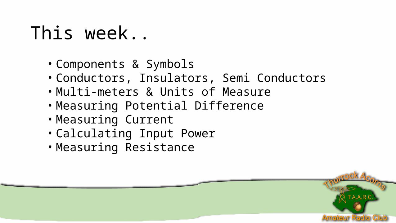
• Components & Symbols
Identify resistors, capacitors including fixed, variable and electrolytic types, inductors, transformers, diodes, transistors, integrated circuits, crystals, microphones and loudspeakers.
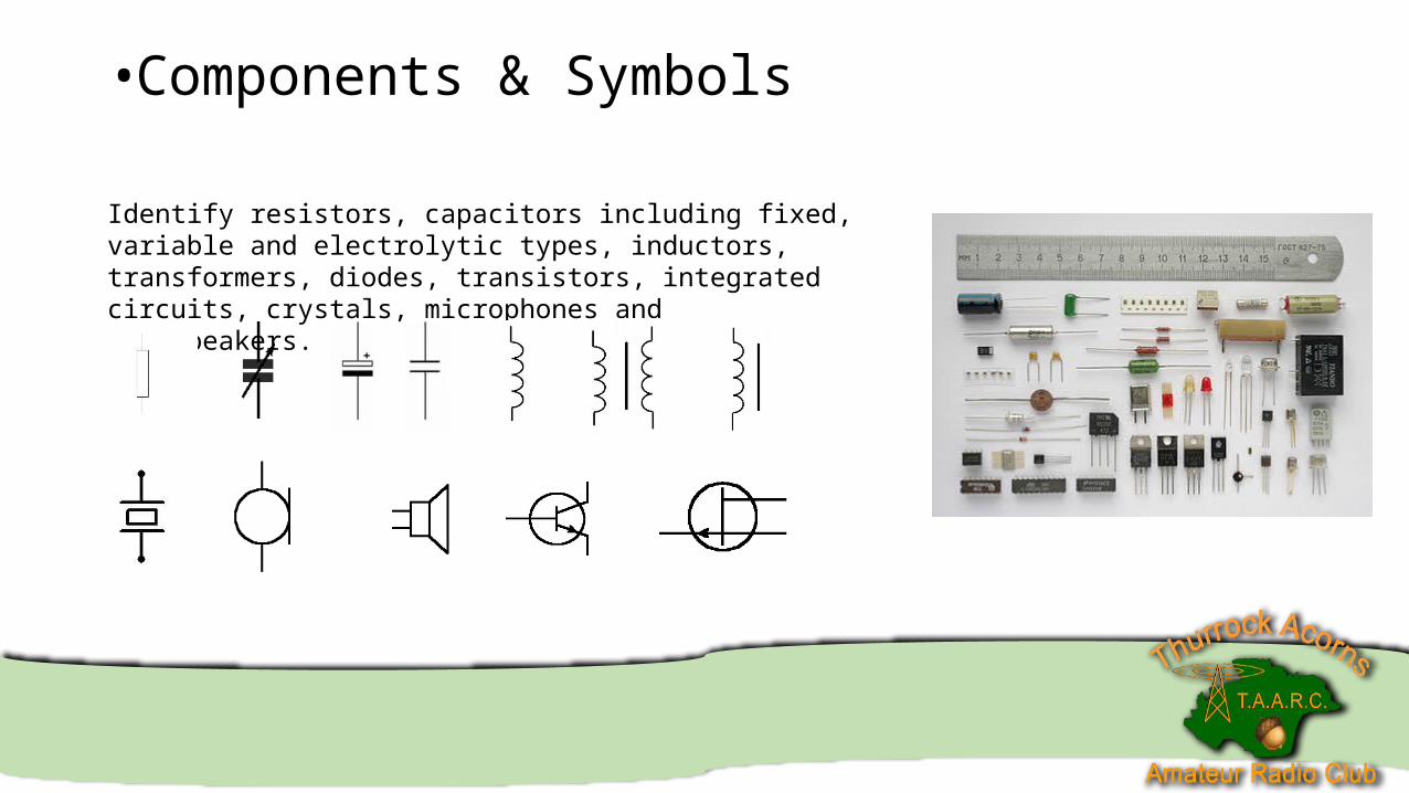
• Conductors, Insulators, Semi ConductorsFirst we need to understand Electrons.
N – Neutrons – Electrons + Protons*Copper Atom
Atoms have a positively charged centre (nucleus). Orbiting around the centre are neutrons. Neutrons are negatively charged. There are often layers of neutrons like the layers of an onion.
The neutrons further away from the centre have less attraction to the centre. These electrons can be made to move from one atom to another by applying Potential difference.
• Conductors, Insulators, Semi ConductorsWhat is a conductor?
Conductors have a naturally low resistance because of their freely available mobile electrons.
Metals are good conductors, some common metals used are;
Copper, brass, steel, and nickel.
• Conductors, Insulators, Semi ConductorsWhat is a conductor.
• Conductors, Insulators, Semi ConductorsWhat is an insulator?
• Insulators have a naturally high resistance because their electrons are so tightly bound that there are virtually no mobile electrons.
• Insulators are used to stop current flowing.
Examples
Wood, rubber, plastics, ceramic, glass, and dry air.
Insulators can conduct on their surface, for example when wood becomes wet, or when there is high moisture in the air.
• Insulators can allow current to flow if the potential difference is too high at its ends.
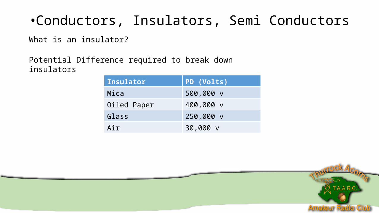
• Conductors, Insulators, Semi ConductorsWhat is an insulator?
Potential Difference required to break down insulators
Insulator PD (Volts)
Mica 500,000 v
Oiled Paper 400,000 v
Glass 250,000 v
Air 30,000 v
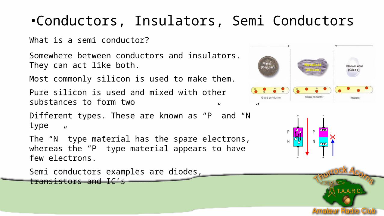
• Conductors, Insulators, Semi ConductorsWhat is a semi conductor?
Somewhere between conductors and insulators. They can act like both.
Most commonly silicon is used to make them.
Pure silicon is used and mixed with other substances to form two
Different types. These are known as “P” and “N” type
The “N” type material has the spare electrons, whereas the “P” type material appears to have few electrons.
Semi conductors examples are diodes, transistors and IC’s
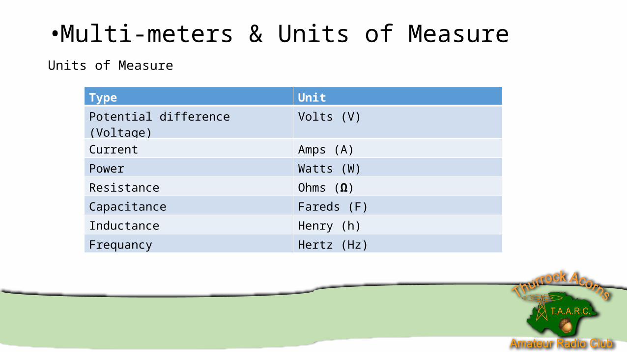
•Multi-meters & Units of MeasureUnits of Measure
Type Unit
Potential difference (Voltage) Volts (V)
Current Amps (A)
Power Watts (W)
Resistance Ohms (Ω)
Capacitance Fareds (F)
Inductance Henry (h)
Frequancy Hertz (Hz)
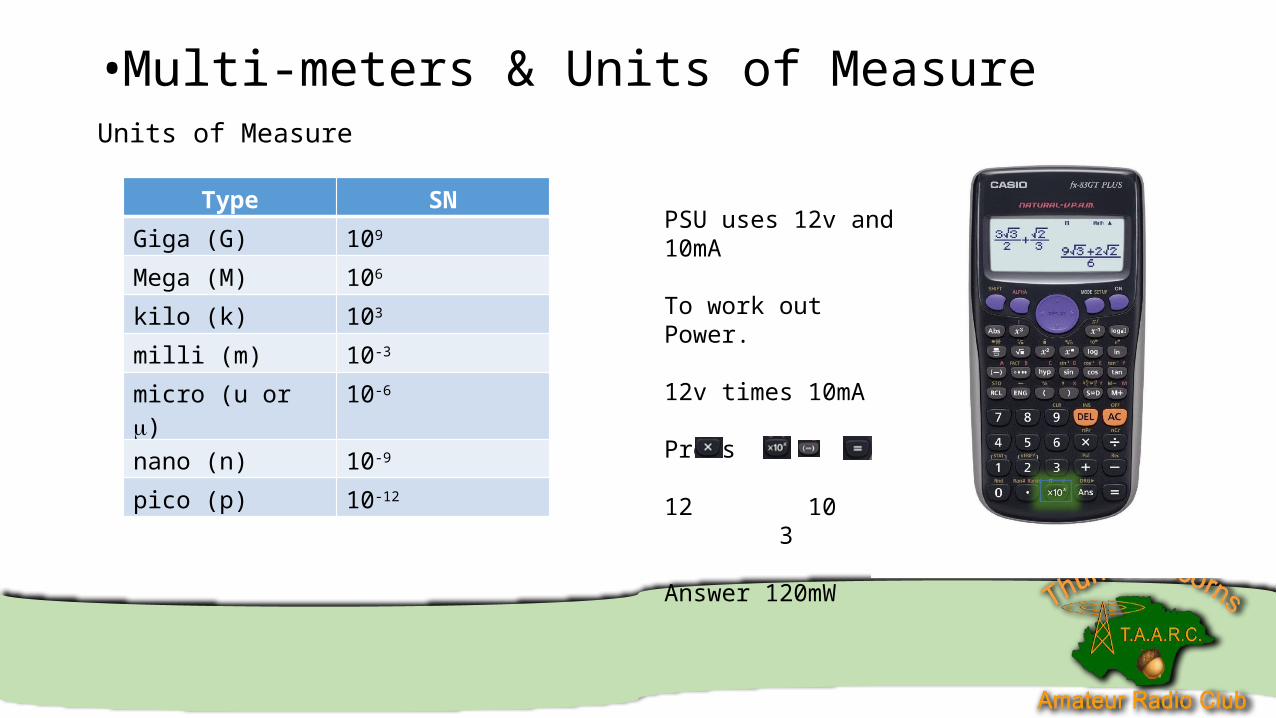
•Multi-meters & Units of MeasureUnits of Measure
Type SN
Giga (G) 109
Mega (M) 106
kilo (k) 103
milli (m) 10-3
micro (u or ) 10-6
nano (n) 10-9
pico (p) 10-12
PSU uses 12v and 10mA
To work out Power.
12v times 10mA
Press
12 10 3
Answer 120mW
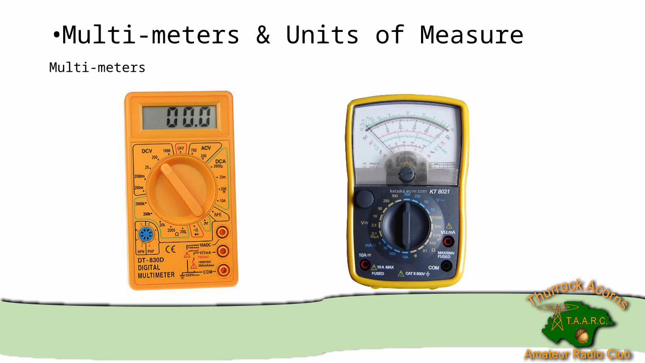
•Multi-meters & Units of MeasureMulti-meters
•Multi-meters & Units of MeasureMulti-meters
There are two main type of meters – Analogue and Digital. Both of them have advantages and disadvantages.
Analogue – Better at reading a variable measurement where you wish to see the peak value. On a digital display as it is changing it is hard to tell. With the needle movement you can pick out the peak a lot more easily.
Digital – Digital meters can have their positive and negative probes connected around the wrong way, where as with an analogue meter this can cause damage.
•Multi-meters & Units of MeasureMulti-meters
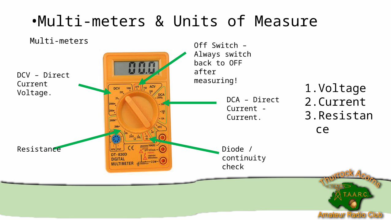
DCV – Direct Current Voltage.
Resistance
Off Switch – Always switch back to OFF after measuring!
DCA – Direct Current - Current.
Diode / continuity check
1. Voltage2. Current3. Resistance
•Multi-meters & Units of MeasureMulti-meters
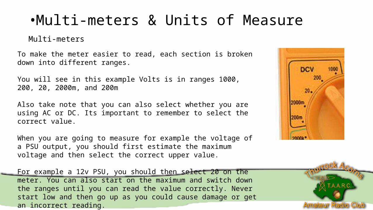
To make the meter easier to read, each section is broken down into different ranges.
You will see in this example Volts is in ranges 1000, 200, 20, 2000m, and 200m
Also take note that you can also select whether you are using AC or DC. Its important to remember to select the correct value.
When you are going to measure for example the voltage of a PSU output, you should first estimate the maximum voltage and then select the correct upper value.
For example a 12v PSU, you should then select 20 on the meter. You can also start on the maximum and switch down the ranges until you can read the value correctly. Never start low and then go up as you could cause damage or get an incorrect reading.
•Multi-meters & Units of MeasureMulti-meters
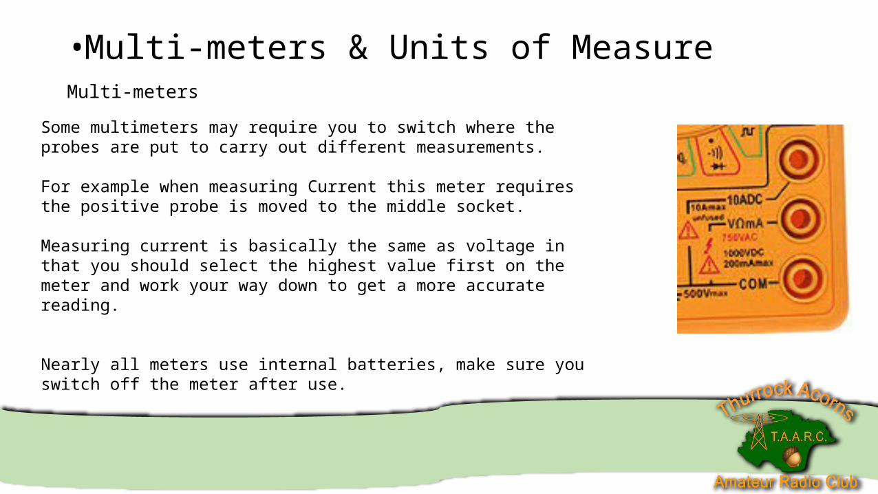
Some multimeters may require you to switch where the probes are put to carry out different measurements.
For example when measuring Current this meter requires the positive probe is moved to the middle socket.
Measuring current is basically the same as voltage in that you should select the highest value first on the meter and work your way down to get a more accurate reading.
Nearly all meters use internal batteries, make sure you switch off the meter after use.
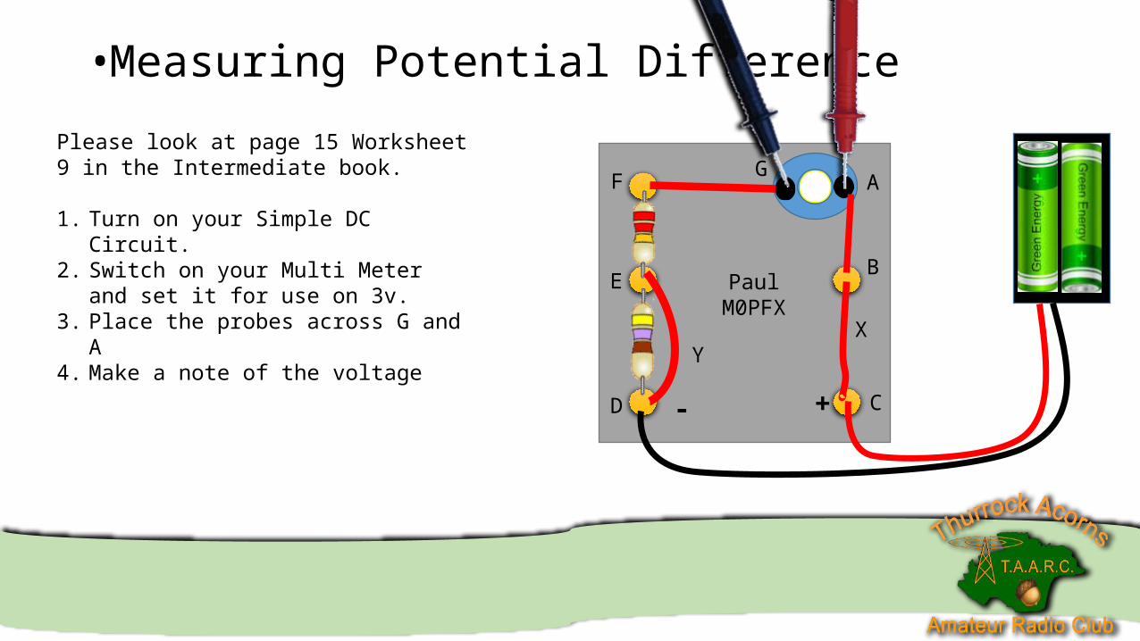
•Measuring Potential Difference
PaulM0PFX
A
B
CD
E
F G
YX
+-
Please look at page 15 Worksheet 9 in the Intermediate book.
1. Turn on your Simple DC Circuit.2. Switch on your Multi Meter and set it for
use on 3v.3. Place the probes across G and A4. Make a note of the voltage
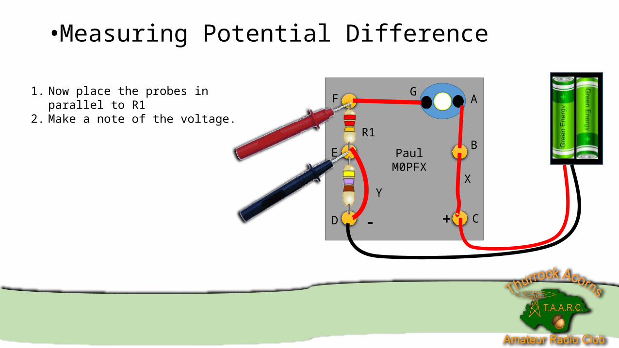
•Measuring Potential Difference
PaulM0PFX
A
B
CD
E
F G
YX
+-
1. Now place the probes in parallel to R12. Make a note of the voltage.
R1
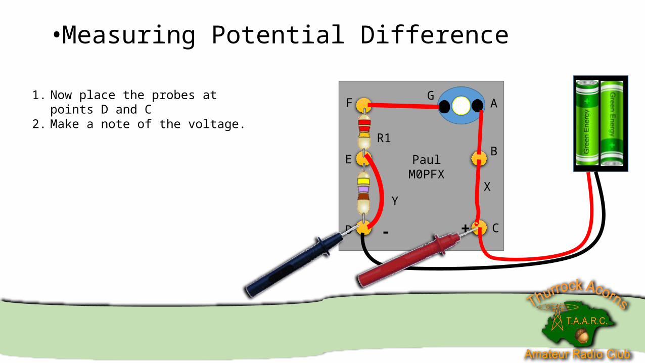
•Measuring Potential Difference
PaulM0PFX
A
B
CD
E
F G
YX
+-
1. Now place the probes at points D and C2. Make a note of the voltage.
R1
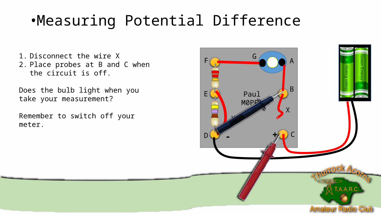
•Measuring Potential Difference
PaulM0PFX
A
B
CD
E
F G
YX
+-
1. Disconnect the wire X2. Place probes at B and C when the circuit is
off.
Does the bulb light when you take your measurement?
Remember to switch off your meter.
•Measuring Potential Difference
PaulM0PFX
A
B
CD
E
F G
YX
+-
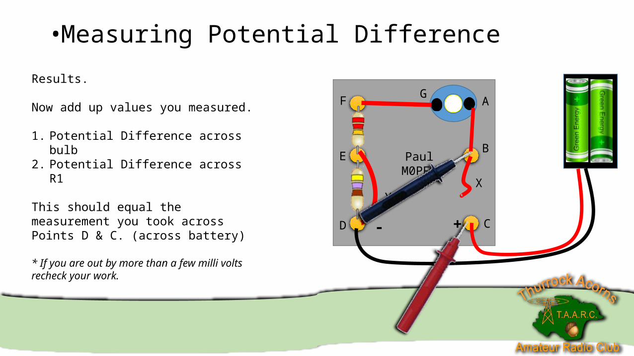
Results.
Now add up values you measured.
1. Potential Difference across bulb2. Potential Difference across R1
This should equal the measurement you took across Points D & C. (across battery)
* If you are out by more than a few milli volts recheck your work.
•Measuring Potential Difference
PaulM0PFX
A
B
CD
E
F G
YX
+-
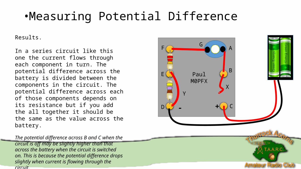
Results.
In a series circuit like this one the current flows through each component in turn. The potential difference across the battery is divided between the components in the circuit. The potential difference across each of those components depends on its resistance but if you add the all together it should be the same as the value across the battery.
The potential difference across B and C when the circuit is off may be slightly higher than that across the battery when the circuit is switched on. This is because the potential difference drops slightly when current is flowing through the circuit.
•Measuring Potential Difference
PaulM0PFX
A
B
CD
E
F G
YX
+-
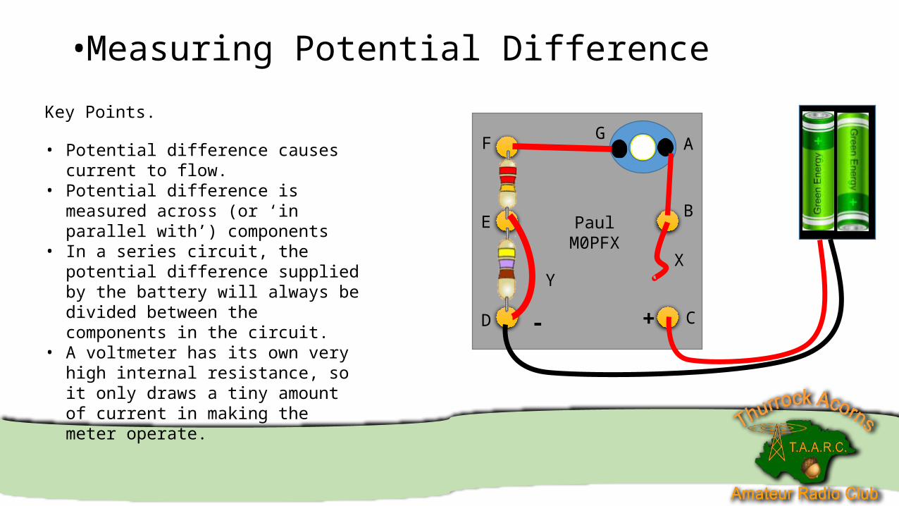
Key Points.
• Potential difference causes current to flow.• Potential difference is measured across (or
‘in parallel with’) components• In a series circuit, the potential difference
supplied by the battery will always be divided between the components in the circuit.
• A voltmeter has its own very high internal resistance, so it only draws a tiny amount of current in making the meter operate.
•Measuring Current
PaulM0PFX
A
B
CD
E
F G
YX
+-
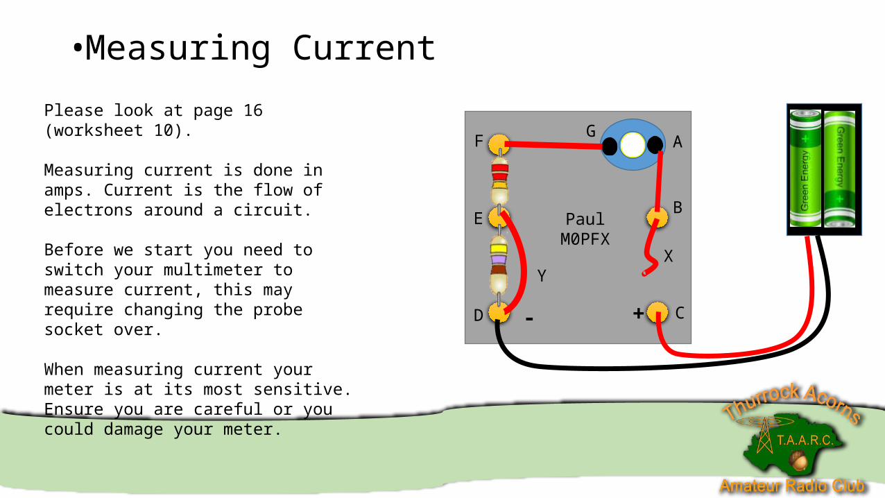
Please look at page 16 (worksheet 10).
Measuring current is done in amps. Current is the flow of electrons around a circuit.
Before we start you need to switch your multimeter to measure current, this may require changing the probe socket over.
When measuring current your meter is at its most sensitive. Ensure you are careful or you could damage your meter.
•Measuring Current
PaulM0PFX
A
B
CD
E
F G
YX
+-
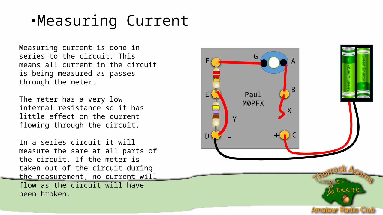
Measuring current is done in series to the circuit. This means all current in the circuit is being measured as passes through the meter.
The meter has a very low internal resistance so it has little effect on the current flowing through the circuit.
In a series circuit it will measure the same at all parts of the circuit. If the meter is taken out of the circuit during the measurement, no current will flow as the circuit will have been broken.
•Measuring Current
PaulM0PFX
A
B
CD
E
F G
YX
+-
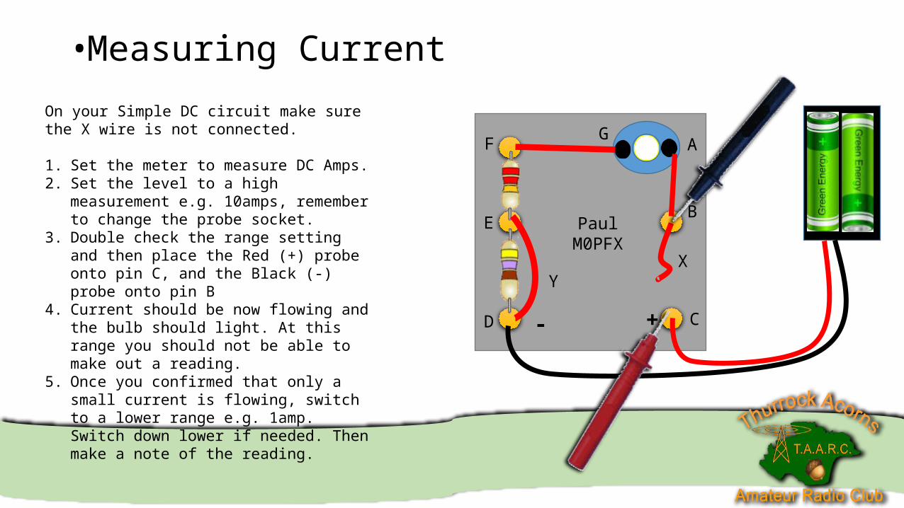
On your Simple DC circuit make sure the X wire is not connected.
1. Set the meter to measure DC Amps.2. Set the level to a high measurement e.g.
10amps, remember to change the probe socket.3. Double check the range setting and then place
the Red (+) probe onto pin C, and the Black (-) probe onto pin B
4. Current should be now flowing and the bulb should light. At this range you should not be able to make out a reading.
5. Once you confirmed that only a small current is flowing, switch to a lower range e.g. 1amp. Switch down lower if needed. Then make a note of the reading.
•Measuring Current
PaulM0PFX
A
B
CD
E
F G
YX
+-
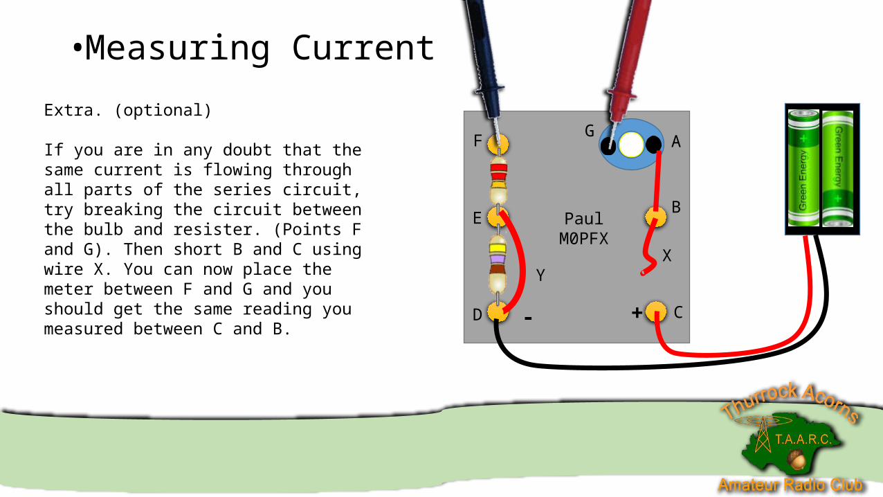
Extra. (optional)
If you are in any doubt that the same current is flowing through all parts of the series circuit, try breaking the circuit between the bulb and resister. (Points F and G). Then short B and C using wire X. You can now place the meter between F and G and you should get the same reading you measured between C and B.
•Measuring Current
PaulM0PFX
A
B
CD
E
F G
YX
+-
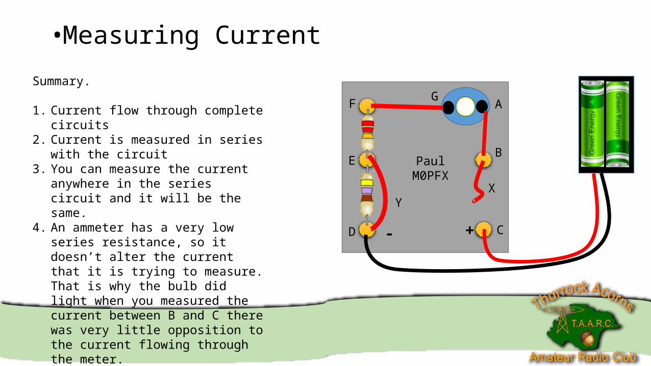
Summary.
1. Current flow through complete circuits2. Current is measured in series with the
circuit3. You can measure the current anywhere in
the series circuit and it will be the same.4. An ammeter has a very low series
resistance, so it doesn’t alter the current that it is trying to measure. That is why the bulb did light when you measured the current between B and C there was very little opposition to the current flowing through the meter.
• Calculating Input Power
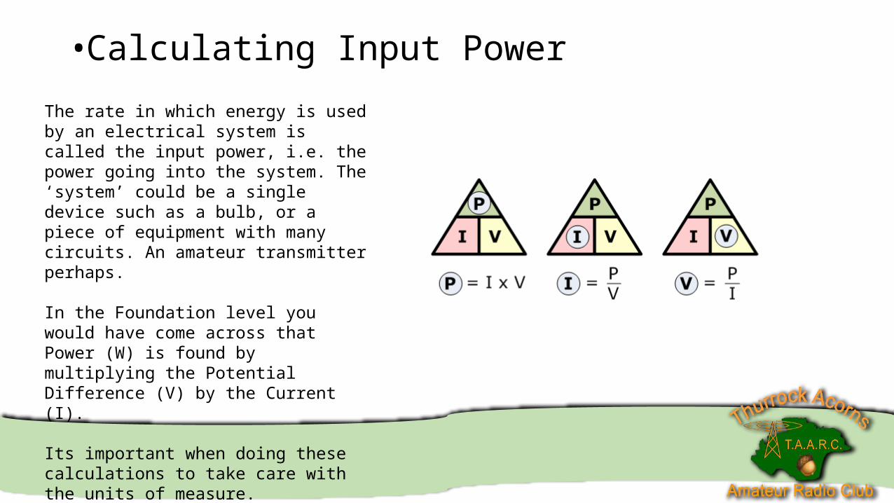
The rate in which energy is used by an electrical system is called the input power, i.e. the power going into the system. The ‘system’ could be a single device such as a bulb, or a piece of equipment with many circuits. An amateur transmitter perhaps.
In the Foundation level you would have come across that Power (W) is found by multiplying the Potential Difference (V) by the Current (I).
Its important when doing these calculations to take care with the units of measure.
e.g. 10mA x 12v is 0.01A x 12v. If you slip up here you will get the wrong answer.
• Calculating Input Power
PaulM0PFX
A
B
CD
E
F G
YX
+-
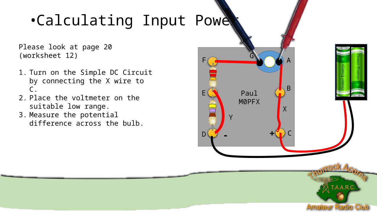
Please look at page 20 (worksheet 12)
1. Turn on the Simple DC Circuit by connecting the X wire to C.
2. Place the voltmeter on the suitable low range.
3. Measure the potential difference across the bulb.
• Calculating Input Power
PaulM0PFX
A
B
CD
E
F G
YX
+-
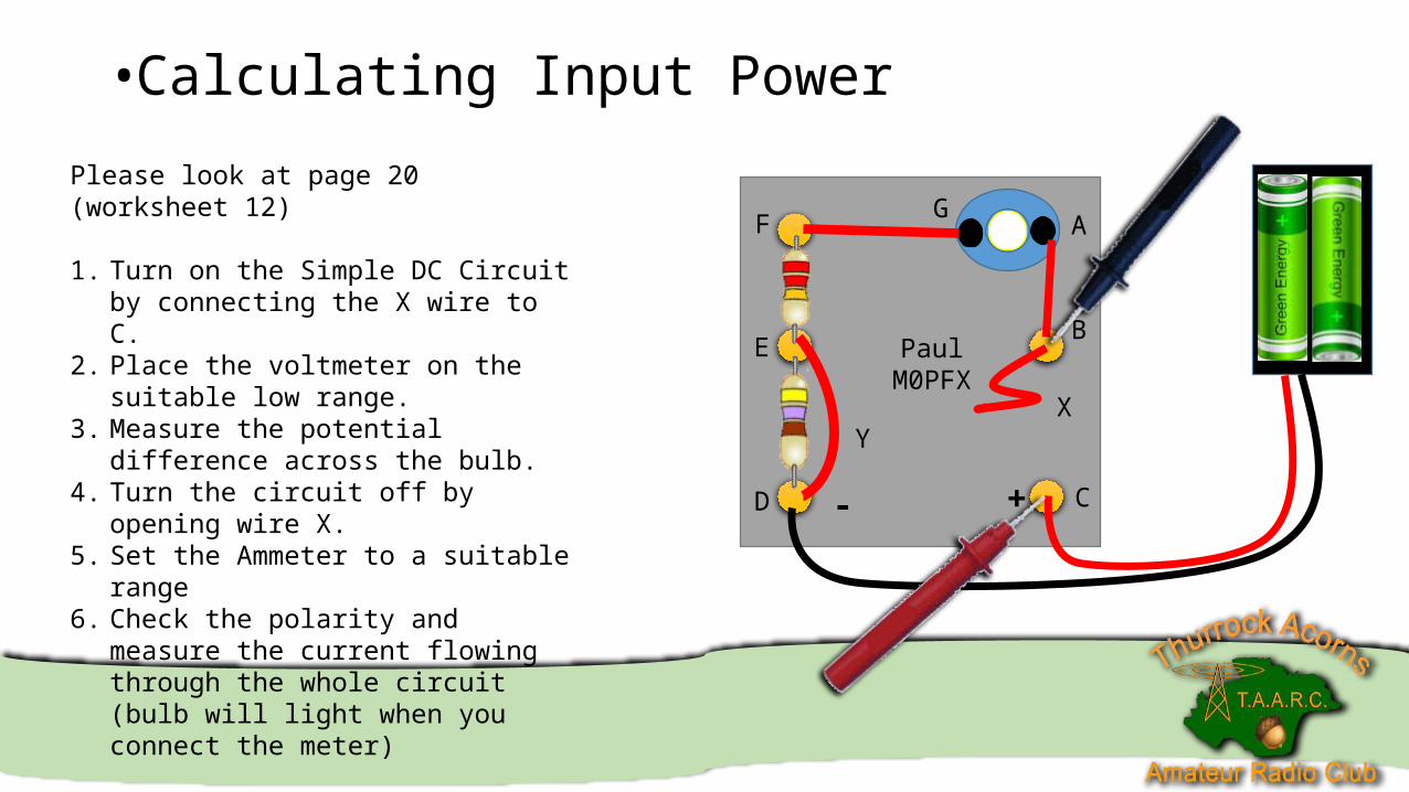
Please look at page 20 (worksheet 12)
1. Turn on the Simple DC Circuit by connecting the X wire to C.
2. Place the voltmeter on the suitable low range.
3. Measure the potential difference across the bulb.
4. Turn the circuit off by opening wire X.5. Set the Ammeter to a suitable range6. Check the polarity and measure the current
flowing through the whole circuit (bulb will light when you connect the meter)
• Calculating Input Power
PaulM0PFX
A
B
CD
E
F G
YX
+-
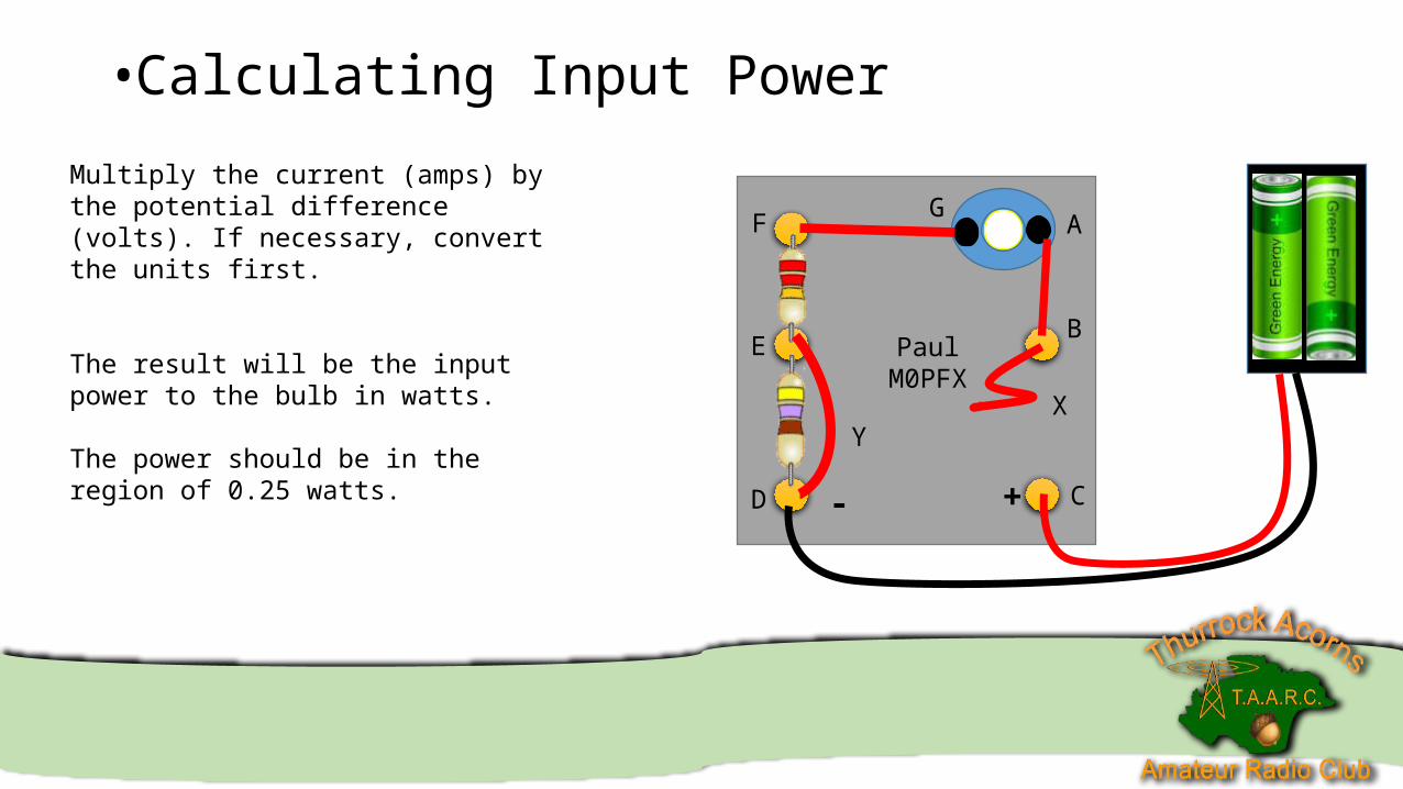
Multiply the current (amps) by the potential difference (volts). If necessary, convert the units first.
The result will be the input power to the bulb in watts.
The power should be in the region of 0.25 watts.
• Calculating Input Power
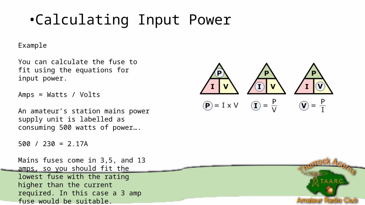
Example
You can calculate the fuse to fit using the equations for input power.
Amps = Watts / Volts
An amateur’s station mains power supply unit is labelled as consuming 500 watts of power….
500 / 230 = 2.17A
Mains fuses come in 3,5, and 13 amps, so you should fit the lowest fuse with the rating higher than the current required. In this case a 3 amp fuse would be suitable.
• Calculating Input Power
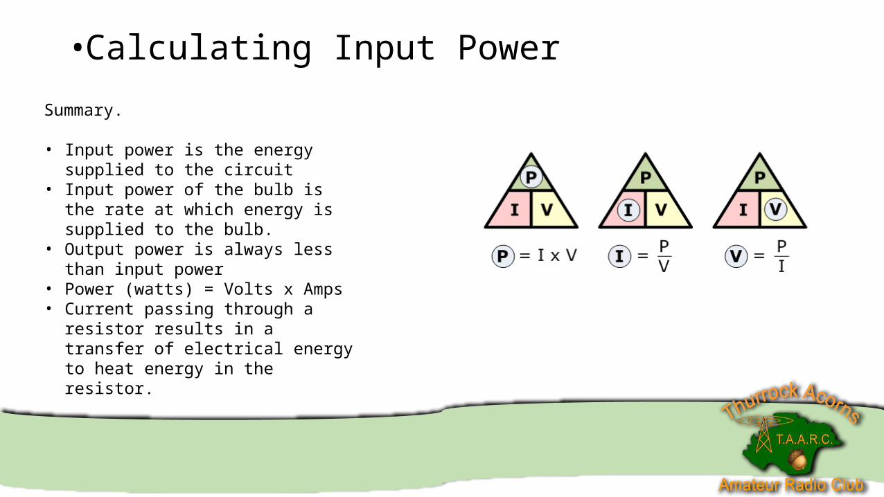
Summary.
• Input power is the energy supplied to the circuit
• Input power of the bulb is the rate at which energy is supplied to the bulb.
• Output power is always less than input power
• Power (watts) = Volts x Amps• Current passing through a resistor results in
a transfer of electrical energy to heat energy in the resistor.
•Measuring Resistance
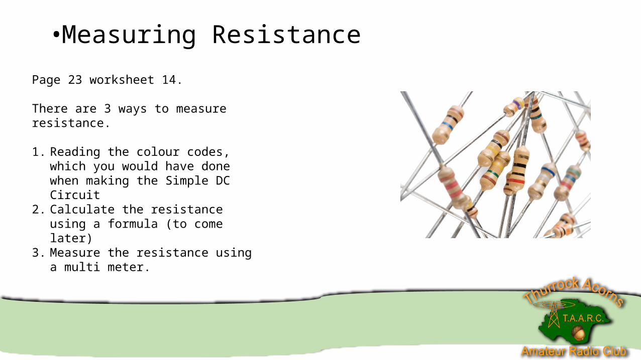
Page 23 worksheet 14.
There are 3 ways to measure resistance.
1. Reading the colour codes, which you would have done when making the Simple DC Circuit
2. Calculate the resistance using a formula (to come later)
3. Measure the resistance using a multi meter.
•Measuring Resistance
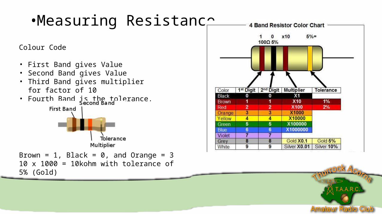
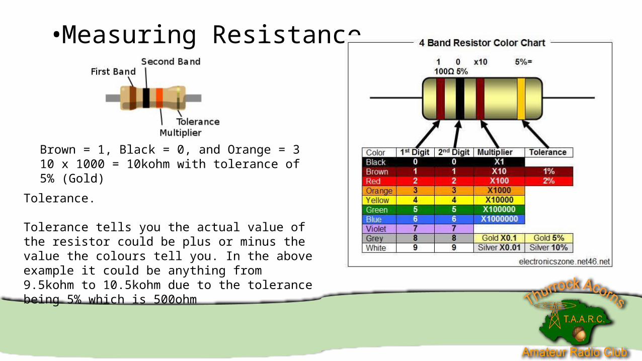
Colour Code
• First Band gives Value• Second Band gives Value• Third Band gives multiplier for factor of 10• Fourth Band is the tolerance.
Brown = 1, Black = 0, and Orange = 3 10 x 1000 = 10kohm with tolerance of 5% (Gold)
•Measuring Resistance
Brown = 1, Black = 0, and Orange = 3 10 x 1000 = 10kohm with tolerance of 5% (Gold)
Tolerance.
Tolerance tells you the actual value of the resistor could be plus or minus the value the colours tell you. In the above example it could be anything from 9.5kohm to 10.5kohm due to the tolerance being 5% which is 500ohm
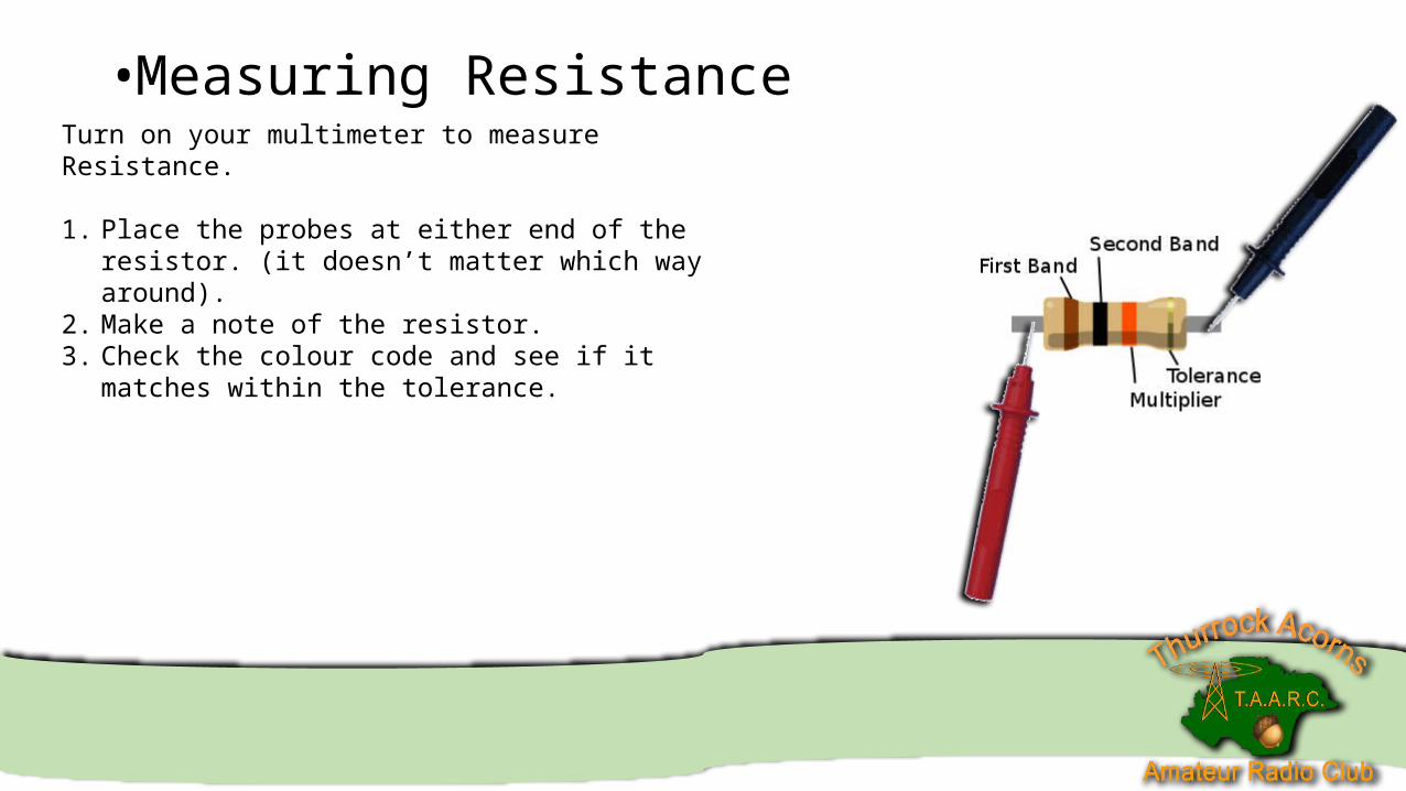
•Measuring ResistanceTurn on your multimeter to measure Resistance.
1. Place the probes at either end of the resistor. (it doesn’t matter which way around).
2. Make a note of the resistor.3. Check the colour code and see if it matches within the
tolerance.
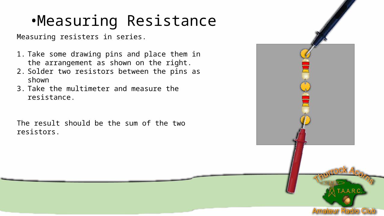
•Measuring ResistanceMeasuring resisters in series.
1. Take some drawing pins and place them in the arrangement as shown on the right.
2. Solder two resistors between the pins as shown3. Take the multimeter and measure the resistance.
The result should be the sum of the two resistors.
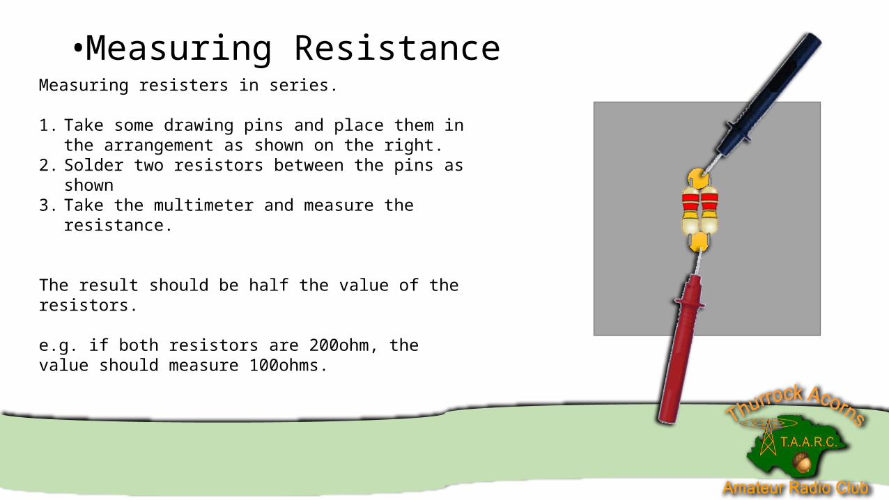
•Measuring ResistanceMeasuring resisters in series.
1. Take some drawing pins and place them in the arrangement as shown on the right.
2. Solder two resistors between the pins as shown3. Take the multimeter and measure the resistance.
The result should be half the value of the resistors.
e.g. if both resistors are 200ohm, the value should measure 100ohms.
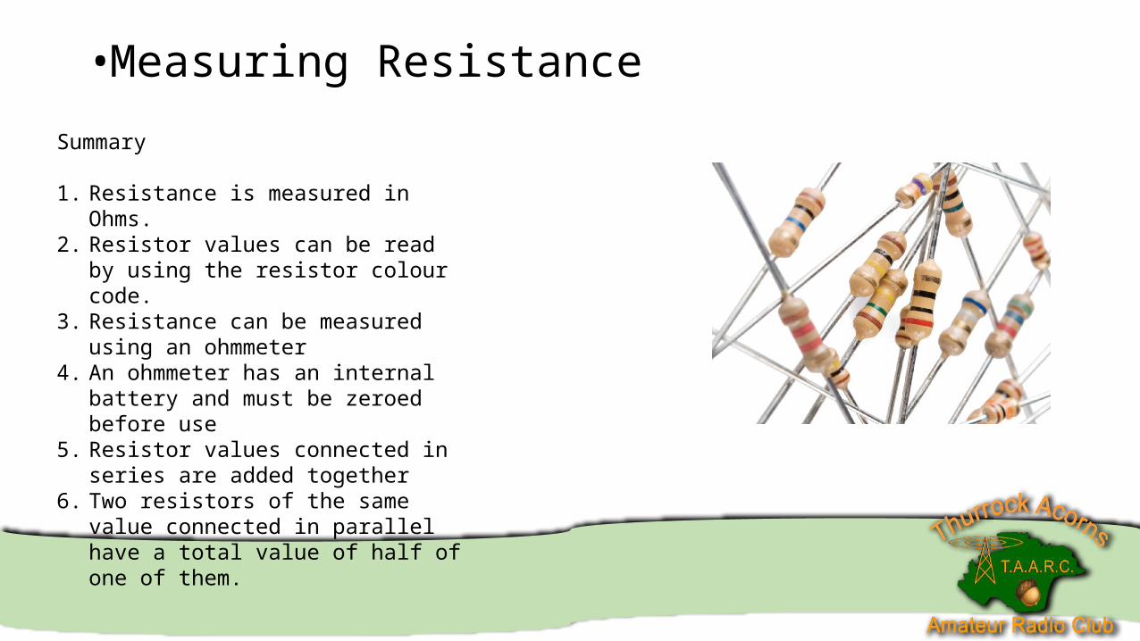
•Measuring Resistance
Summary
1. Resistance is measured in Ohms.2. Resistor values can be read by using the
resistor colour code.3. Resistance can be measured using an
ohmmeter4. An ohmmeter has an internal battery and
must be zeroed before use5. Resistor values connected in series are
added together6. Two resistors of the same value connected
in parallel have a total value of half of one of them.
•Next Week
Technical Basics and Components Part 2
Diode and Transistors..