Embed Size (px)
Citation preview
Intermediate techniques formodeling yard detailsStuns’l Boom Irons, stirrups,footropes, yard cleats, blocksand more...Have you ever examined a kit model built by a friend andwondered how they managed to expertly depict the deckfittings? This was only their second or third attempt atmodeling yet the planking is very well done. The woodworking skills demonstrated are inspiring. You look closelyat the joinery and sharp craftsmanship of the hull anddeck planking. The hull planking has perfectly cut andpositioned stealers and drop planks. The deck planking isnibbed cleanly into the margin plank. Time and care wastaken to simulate the caulking between the planks. It’squite an accomplishment considering you friend hasn’t yetpurchased a belt sander, mini table saw, miter chop saw,mini lathe etc. It was all accomplished with unwaveringcare and attention to the details.
Then your eyes slowly wander up to the masts, yards andrigging. Your initial joy is soon replaced with confusion anddisappointment. The same level of detail used to modelthe hull was not carried over to the masts and yards. Youwonder why. It almost looks as though there are two dif-ferent models that were mistakenly joined together. Theyards in particular, although cleanly made don’t have thesame level of detail and historical correctness.
You are probably already aware of the fact that most kitsand there instructions show few details. They are usuallywritten as a broad overview and summary. The few detailsmentioned get even sparser and more simplified when itcomes to mast and spar creation. Most likely, the modelbuilder is directed to use the kit supplied eye bolts for thestirrups. These are simply glued into pre-drilled holes
along the bottom of the yard arm. To make the footropes(horses), kit supplied rigging line is reeved through theeyebolts and tied off around the yard. But due to thenature of the supplied line it is impossible to get them tohang with a natural swag. The line was wound so tightlyaround the plastic bobbin from the kit that it has ugly kinksand twists which cannot be removed after rigging it.
The stuns’l boom irons are usually constructed from wireand simply bent with little loops on both ends and slippedonto the yard arm. They look very much like a first projectrather than a second or third attempt. I believe the reasonfor such a disparity between the hull and yard details isdue to the fact that less “how-to” information is readilyavailable. In addition to the poor direction provided in kitinstructions, there are also many popular modeling booksdirected towards the beginner with poor techniquesdescribed. For example, in “Ship Modelling Simplified” byFrank Mastini you would read this…
“Stuns’l booms were supported bytwo iron rings. The inside ring wrappedaround the boom and was fixed to ashort iron rod that ran to another ringsecured to the yard. The one on the endof the yard was supported by a bent ironrod inserted into the yard end. Theserings are sometimes supplied in the kits,but if not, you can make your own. Hereare some simple ways to make them. Forthe one at the end, use brass wire. Bendit over the tip of a pair of roundnosepliers or over a dowel of the right sizeto form the ring, and then bend the wire.”
These less-than-ideal alternatives for yard and mast con-struction often linger on well into a third or fourth modelingproject. Most of the builder’s attention is usually devotedto improving their skills to construct the hull and its manydeck fittings.
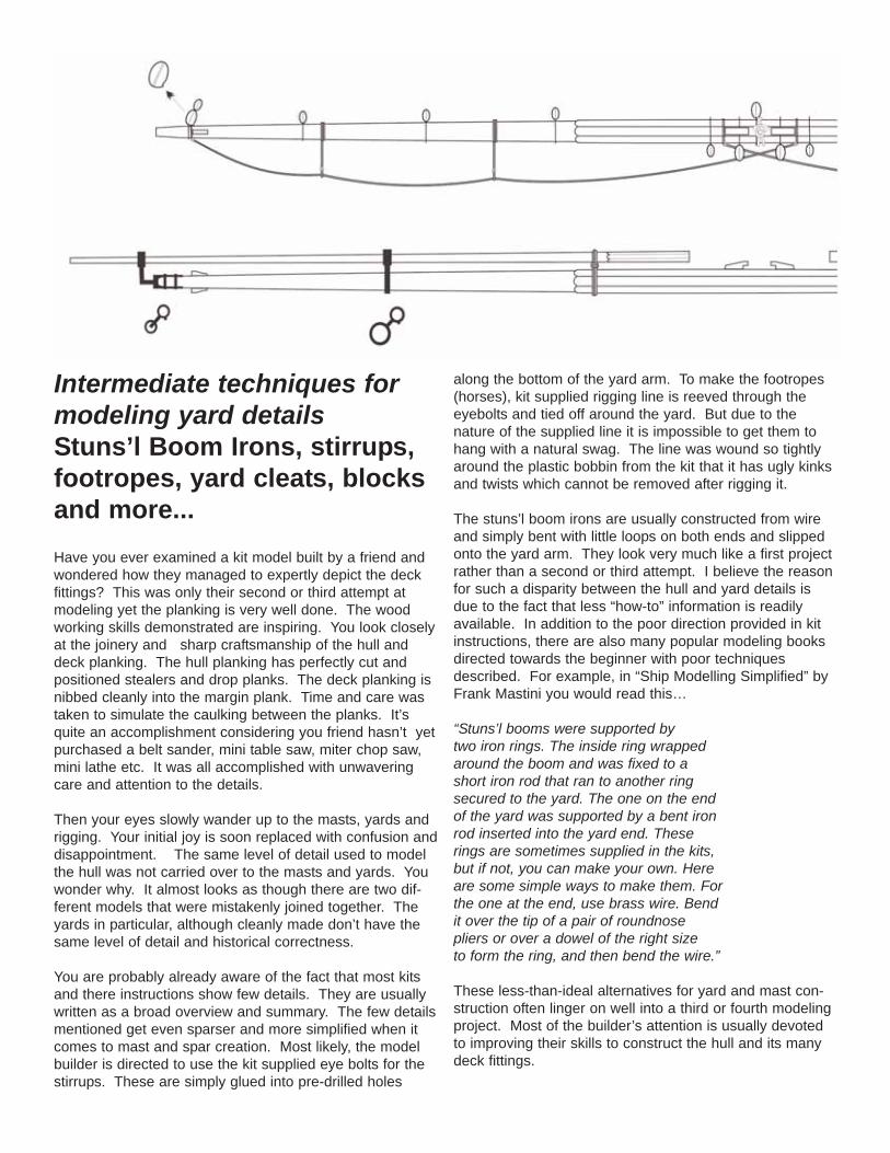
What follows are a few intermediate techniques for produc-ing better results when modeling your yard arms. Theycan be achieved without the need to purchase additionalmilling or soldering equipment. Simple materials can befound at any local hardware or crafts store (or maybe evenyour spare parts box). The exercise below documents thebuilding of a lower yard for the main course (circa 1800).
If you are building a kit I can assume that birch or bass-wood dowels were probably supplied for all of the mastsand spars. Taper the appropriate diameter dowel on bothends to match the plans provided. But before doing so,drill a small hole into the ends of each yard arm. It will beeasier to locate and drill these holes now while the dowelhas much more meat on it. It is less likely to split at thistime rather than after tapering the ends down to a muchsmaller diameter. The outer stuns’l boom irons will beinserted into these holes later.
Whether this is noted on your plans or not, most loweryards for Napoleonic ships were constructed with the cen-ter of the yard “octagon-shaped”. The eight-sided sectionof the yard usually covered about one quarter of its length.While shaping your spar, try to avoid tapering this centersection. You can place batten strips around the yard toachieve this eight-sided geometry. Not being tapered it willbe much easier to prepare and assemble the batten stripsaround this section of the yard. This section of the yardcan be tapered after the battens are added.
Select some wood strips no thicker than 1/32” for the bat-tens. To help find the correct width for these strips you willneed to measure the diameter of the center of the yard.Then divide that by eight. Wrapping a strip of paperaround the center of the yard is an easy way to find itsdiameter and divide up the resulting space. When cuttingyour strips to the width needed, make them slightly wider.Not by much. Since you are covering a rounded surface,the outside edges of each strip need to be beveled so youget a tight fit around the yard (Hence the need to makethem slightly wider). The ends of these battens can also
be rounded off as shown in the photo provided to createsome extra detail. Once glued around the center of theyard any small gaps can be filled with wood filler and sand-ed.
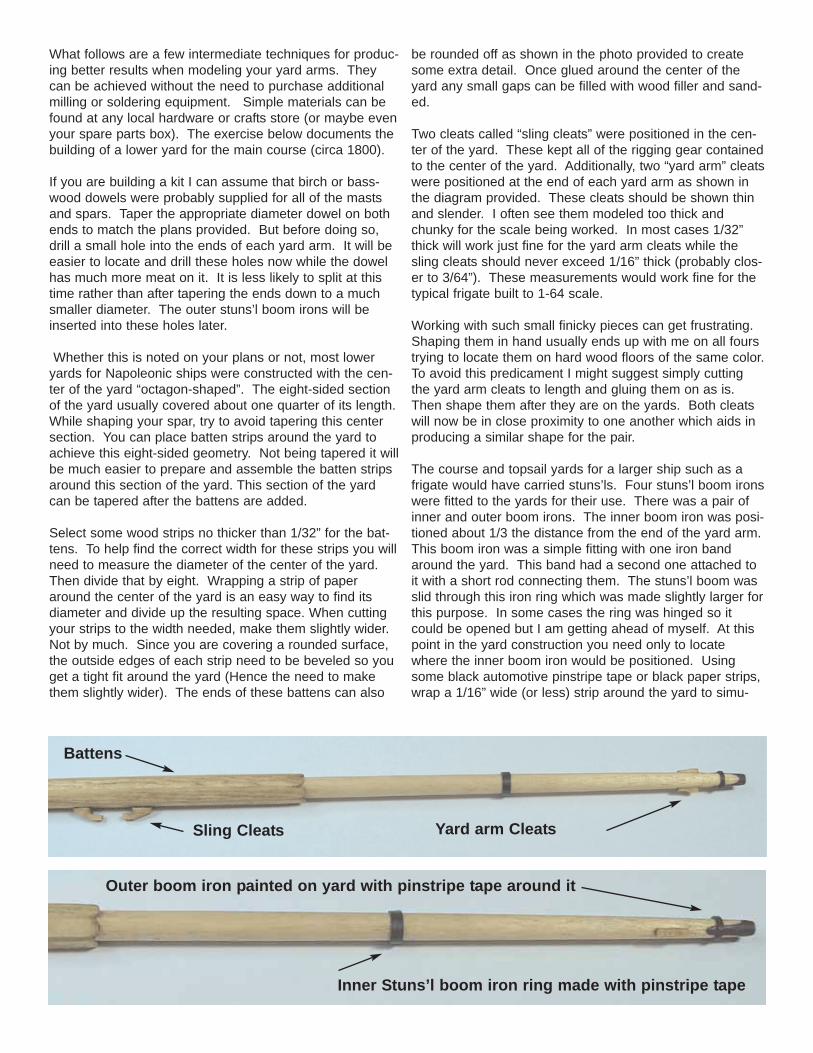
Two cleats called “sling cleats” were positioned in the cen-ter of the yard. These kept all of the rigging gear containedto the center of the yard. Additionally, two “yard arm” cleatswere positioned at the end of each yard arm as shown inthe diagram provided. These cleats should be shown thinand slender. I often see them modeled too thick andchunky for the scale being worked. In most cases 1/32”thick will work just fine for the yard arm cleats while thesling cleats should never exceed 1/16” thick (probably clos-er to 3/64”). These measurements would work fine for thetypical frigate built to 1-64 scale.
Working with such small finicky pieces can get frustrating.Shaping them in hand usually ends up with me on all fourstrying to locate them on hard wood floors of the same color.To avoid this predicament I might suggest simply cuttingthe yard arm cleats to length and gluing them on as is.Then shape them after they are on the yards. Both cleatswill now be in close proximity to one another which aids inproducing a similar shape for the pair.
The course and topsail yards for a larger ship such as afrigate would have carried stuns’ls. Four stuns’l boom ironswere fitted to the yards for their use. There was a pair ofinner and outer boom irons. The inner boom iron was posi-tioned about 1/3 the distance from the end of the yard arm.This boom iron was a simple fitting with one iron bandaround the yard. This band had a second one attached toit with a short rod connecting them. The stuns’l boom wasslid through this iron ring which was made slightly larger forthis purpose. In some cases the ring was hinged so itcould be opened but I am getting ahead of myself. At thispoint in the yard construction you need only to locatewhere the inner boom iron would be positioned. Usingsome black automotive pinstripe tape or black paper strips,wrap a 1/16” wide (or less) strip around the yard to simu-
Battens
Sling Cleats
Inner Stuns’l boom iron ring made with pinstripe tape
Outer boom iron painted on yard with pinstripe tape around it
Yard arm Cleats
late this iron band. If you have decided to paint your yardsblack this would be the time to do it. If not, then somepreparation for the outer boom irons can be completednext.
The outer boom irons consisted of an iron ring to supportthe boom also. A metal rod was also attached to it. Thistime however it is bent to form a goose neck. The end ofthe goose neck had iron jaws which were slid onto theyard arm. The jaws were usually let into the yard arm andbolted on. The outside surface of the jaws was more-or-less flush with the surface of the yard arm. One or twoiron bands were wrapped around the jaws and yard arm tohelp strengthen the whole assembly.
To simulate the jaws simply paint them onto the ends ofthe yard arms. Since they were let into the yard arm thismakes perfect sense and is a much simpler solution thancreating an actual set of metal jaws. No soldering or com-plicated metal work is needed. Once finished wrap somepinstripe tape or paper around the jaws to simulate the ironbands securing them. These bands should not be as wideas the one used to simulate the inner boom iron. I madethem no wider than 1/32”. See the photo provided thatshows the yard arm at this stage of construction.
Foot ropes were hung from the yard so the sailor couldhave a place to stand while working the sails. They werehung from lengths of rope wrapped three times around theyard arm called “stirrups”. The stirrups had an eye or thim-ble worked into the lower end and the footropes would bestrung through them. As many as four stirrups were usedon the yards of larger ships but as few as one or two for
smaller yards or vessels. The stirrups and footropes forour exercise could be made from rigging line. It usuallyresults in a maddening session of adjusting and readjust-ing after they are rigged. Various stiffening agents can beused to process the line so it will lay with a natural swag.Some of the kinks and twists can be worked out of the lineahead of time of course. But as an alternative, 28 gaugeblack wire can be substituted. It can be used solely for thestirrups or for footropes as well. If bent around the yardand treated as if it were rigging line the results just mightsurprise you. An eye is formed on the end of the wire withsome needle nose pliers. This would normally be sufficientfor simulating the eye and thimble on the end of the stir-rup. But to push the realism a bit further you could usesome sewing thread to create a “cosmetic” seizing abovethe eye. It serves no purpose but to cosmetically enhancethe idea that the stirrup is made from actual rigging line.
According to Steel, the stirrups would hang roughly 3 feetbelow the yard. At this distance the sailor would be able torest his stomach on the yard while standing on thefootropes. This oftens looks too long to me and I will attimes shorten the distance slightly. Steele’s description isworth noting.
“Horses, prepared on shore, go over the yard-arms with aneye in their outer ends, and stop against the cleats, andhang about three feet below the yard. To keep the horsemore parallel to the yard, it is suspended, at proper dis-tances, by ropes, called stirrups, prepared on shore, thathave thimbles or eyes spliced in their lower ends, throughwhich the horses pass; the upper ends are opened, plaited,and flattened to the yard with three round turns and nailed.”
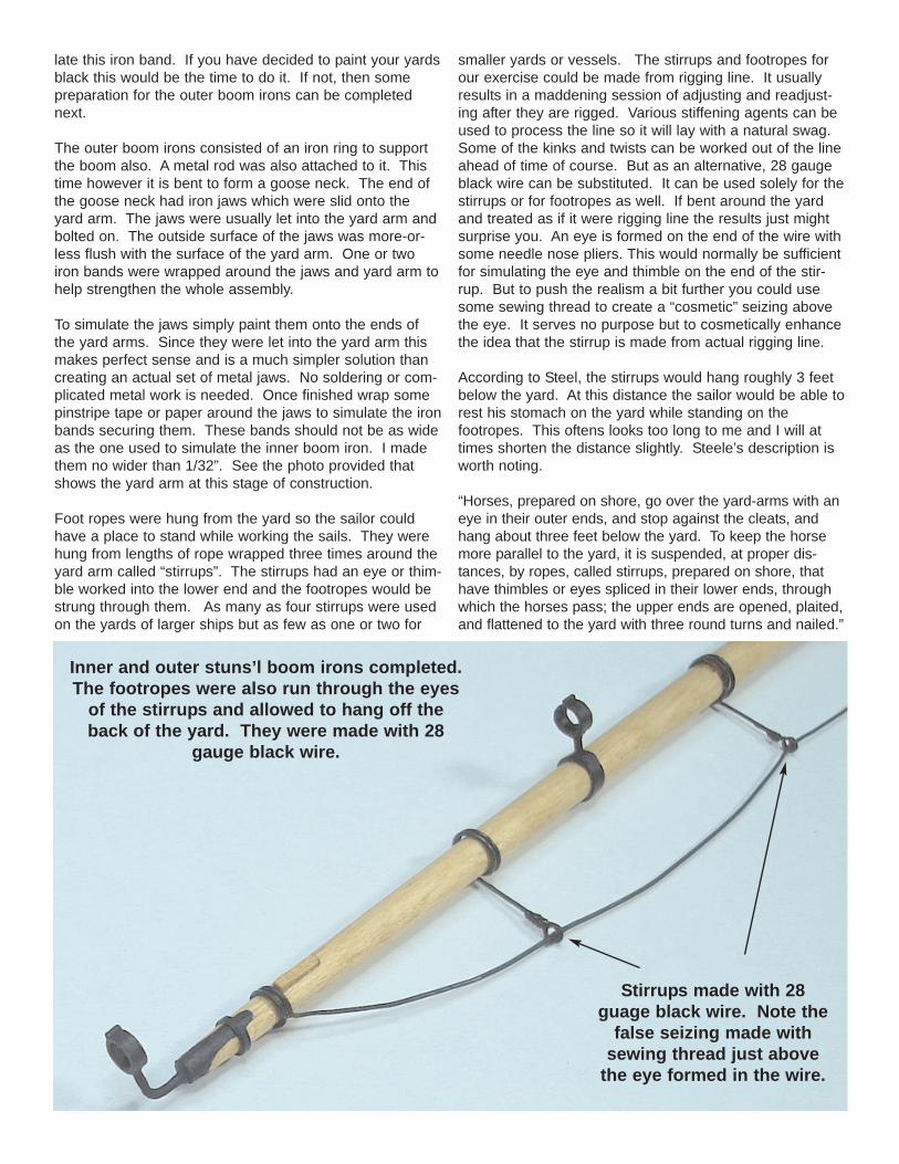
Stirrups made with 28guage black wire. Note the
false seizing made withsewing thread just above
the eye formed in the wire.
Inner and outer stuns’l boom irons completed.The footropes were also run through the eyes
of the stirrups and allowed to hang off theback of the yard. They were made with 28
gauge black wire.
I will create two stirrups on each yard arm as if it werebeing used to support the footropes for a typical brig of1800. Hanging them from the bottom/center of the yardcan help conceal the fact that they were made from wire.In actual use they would have hung off the back side of theyard. You could use either approach. The footropes (28gauge wire) is run through the eyes on the stirrups andwrapped twice around the yard on both ends. You can seein the photo provided where each end of the footrope islocated. Use a needle nose pliers to create a slight bendin the footrope were it passes through the eye of each stir-rup. Then create a natural looking swag between eachsegment of the footrope by shaping them with your fingers.The trick to using wire is NOT to make the stirrups andfootropes hang too perfectly. You might want to actuallyintroduce some “imperfection” to how they hang. This willgo a long way in helping push the illusion. Draping themwith near perfect hanging swags is something that lendsitself to closer inspection. Introducing an ever-so-slightbend now and again will do wonders for the overall affect.
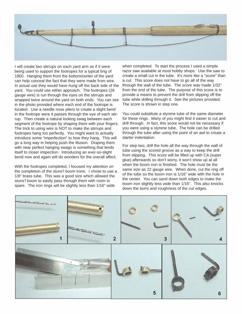
With the footropes completed, I focused my attention onthe completion of the stuns’l boom irons. I chose to use a1/8” brass tube. This was a good size which allowed thestuns’l boom to easily pass through them with room tospare. The iron rings will be slightly less than 1/16” wide
when completed. To start the process I used a simplerazor saw available at most hobby shops. Use the saw tocreate a small cut in the tube. It’s more like a “score” thana cut. This score does not have to go all of the waythrough the wall of the tube. The score was made 1/32”from the end of the tube. The purpose of this score is toprovide a means to prevent the drill from slipping off thetube while drilling through it. See the pictures provided.The score is shown in step one.
You could substitute a styrene tube of the same diameterfor these rings. Many of you might find it easier to cut anddrill through. In fact, this score would not be necessary ifyou were using a styrene tube. The hole can be drilledthrough the tube after using the point of an awl to create astarter indentation.
For step two, drill the hole all the way through the wall oftube using the scored groove as a way to keep the drillfrom slipping. This score will be filled up with CA (superglue) afterwards so don’t worry, it won’t show up at allwhen the boom iron is finished. The hole must be thesame size as 22 gauge wire. When done, cut the ring offof the tube so the boom iron is 1/16" wide with the hole inthe center. You can sand down both edges to make theboom iron slightly less wide than 1/16". This also knocksdown the burrs and roughness of the cut edges.
Step three - Bend a piece of 22 gauge wire to form the“goose neck” for the outside boom iron. The inside boomiron only requires a straight piece. Make them extra longso you will have a handle to hold while painting them later.
Step four - Glue the 22 gauge pieces of wire into position.Push them into the holes so the wire protrudes slightly intothe tube. Once the glue dries, file the protrusion downflush with the inside wall of the tube. It will be quite sturdy Ipromise you. Remember, the stuns’l booms will be underno tension what so ever. There is really no need to solderthese pieces together. The glue will provide more than suf-ficient strength here. Cut tiny pieces of 28 black gaugewire in preparation for the next step.
Step five – Glue the tiny lengths of 28 gauge wire to therings. They will simulate the hinges that are often seen onsome boom irons from this time period. You could addmore detail if you wish. But this is usually sufficient andproduces a nice clean simplified boom iron. File or sandthe ends of the wire flush with the width of the tube.
Step six – To complete the boom irons paint them black.See the photos provided.
The boom irons can now be added to the yard assembly.They would have been set to a 45 degree angle above theyard on the fore side. Slide the end of the goose neck forthe outer boom iron into the hole you drilled on the end ofthe yard. Establish the correct angle as noted. The innerboom iron is simply inserted into a hole drilled through theiron band you made on the yard arm earlier. If you usedpaper or pinstripe tape to simulate the iron band, then youshould start the hole with the point of a sharp awl first.This will prevent the tape from twisting around the drill bitas you make the hole. That would ruin the finish andshape of your iron band. Cut the stem for the inner boomiron to length and insert it into the hole. Touch up anyareas that need some attention with black paint and theprocess is completed. One thing I will caution folks onwould be to avoid positioning the rings of the boom irons
too far away from the yard arm. I would suggest they beplaced no further than 1/16” in 1:64 scale.
The stuns’l booms were made from a 3/64” diameterdowel. The outer ends were tapered. The inboard endswere not. In fact, you could sand the inboard end to anoctagon shape. This was sometimes done with the stuns’lbooms and it adds a nice touch to an otherwise plain stick.Slide them through the boom irons and add a drop of glueto prevent them from shifting out of position.
This completes the construction of the yard. At this pointyou can rig all of the various blocks to yard using your rig-ging plan as a guide. If you have decided to show bunt-lines and leech lines these blocks should be rigged towardsthe top-front of the yard as this rigging hung down the frontside of the sail. The clue lines are rigged on the back sideof the sail therefore those blocks should be rigged underthe yard and positioned towards the aft side.
The lower yard around the turn of the 19th century had thetopsail sheet block and lift block stropped together. Thesetwo blocks were rigged to the end of the yard arm againstthe cleats you shaped earlier. You can see them in thediagram provided at the beginning of this article. Theblock for the topsail sheet gives you the opportunity toimprove the look of your model further. In most kits youwould probably be instructed to use a larger single blockfor the topsail sheet and strop a slightly smaller one on topof that for the lift block. If you examined the drawing close-ly you would see that the sheet block has a distinct shape.There is a small lip on the inboard side of the block.Showing this detail would be easy to do. It shows that youput as much thought and detail into the masting and riggingas you did for the hull and deck fittings.
I usually start with a slightly larger kit-supplied block thancalled for in the instructions. I always take the time to preshape all of the kit supplied blocks before using them. Acrude square-shaped block is typically supplied with mostkits. It is dead give-a-away for anyone with a little knowl-
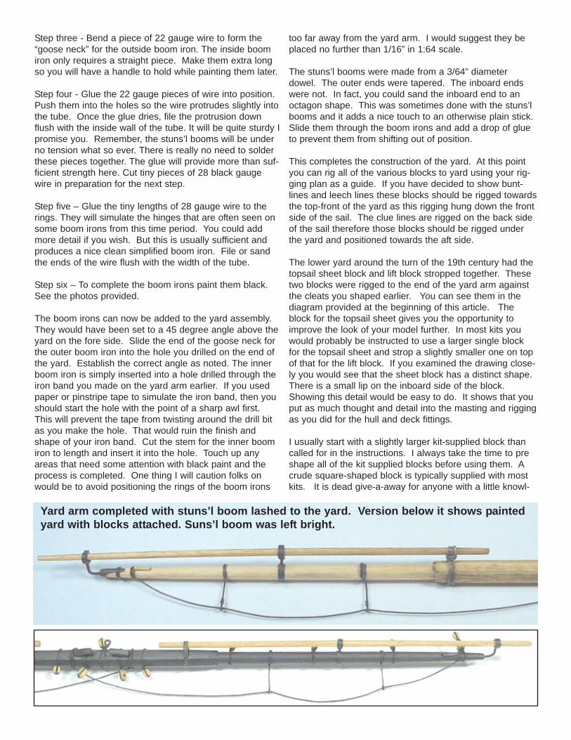
Yard arm completed with stuns’l boom lashed to the yard. Version below it shows paintedyard with blocks attached. Suns’l boom was left bright.
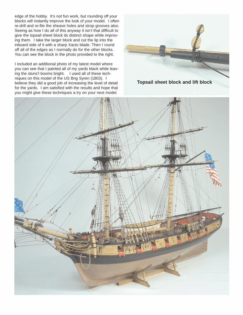
edge of the hobby. It’s not fun work, but rounding off yourblocks will instantly improve the look of your model. I oftenre-drill and re-file the sheave holes and strop grooves also.Seeing as how I do all of this anyway it isn’t that difficult togive the topsail sheet block its distinct shape while improv-ing them. I take the larger block and cut the lip into theinboard side of it with a sharp Xacto blade. Then I roundoff all of the edges as I normally do for the other blocks.You can see the block in the photo provided to the right.
I included an additional photo of my latest model whereyou can see that I painted all of my yards black while leav-ing the stuns’l booms bright. I used all of these tech-niques on this model of the US Brig Syren (1803). Ibelieve they did a good job of increasing the level of detailfor the yards. I am satisfied with the results and hope thatyou might give these techniques a try on your next model.
Topsail sheet block and lift block