Embed Size (px)
Citation preview
INTERNAL ASSESSMENT EXAMINATION – II ANSWER KEY
COURSE: B.E – CSE
OAN551 – SENSORS AND TRANSDUCERS
IAE 1 ANSWER KEY Page 1
PART A - (10 X 1 = 10 marks)
1. _____ is the time required to come to an output value within the specified error level.
(a) Settling time (b) Rise time (c) Response time (d) Delay time
2. A piezo-electrical crystal generates voltage when subjected to ____ force.
(a) Electrical (b) Mechanical (c) Gravity (d) Magnetic
3. An instrument that is capable of measuring only DC is _______.
(a) Moving Coil (b) Moving iron (c) Thermocouple (d) Thermistor
4. Magnetic materials can be tested by _______.
(a) Self inductance bridge (b) Cambell Bridge (c) AC Pot (d) LVDT
5. The household energy meter is ________ instrument.
(a) Indicating (b) Recording (c) Integrating (d) Digital
6. Resistances can be measured with the help of ________.
(a) Ohm meter (b) Ammeter (c) Voltmeter (d) Wattmeter
7. Thermocouple generate output voltage according to _________.
(a) Temperature (b) Humidity (c) Voltage (d) Current
8. Following is (are) the type(s) of Light sensor(s) ________.
(a) Ultrasonic (b) LVDT (c) Photodiode (d) RVDT
9 Smallest change which a sensor can detect is _________.
(a) Resolution (b) Accuracy (c) Precision (d) Stability
10 The sensors are classified on the basis of _________.
(a) Function (b) Performance (c) Output (d) All the above
PART B - (10 X 2 = 20 marks)
11. Label out primary and secondary standards.
Primary standards are made to the highest metrological quality and are the definitive definition
or realization of their unit of measure. The next quality standard in the hierarchy is known as
a secondary standard. Secondary standards are calibrated with reference to a primary standard.
12. List out the type of instrumental errors.
Loading error
Environmental Error
13. Outline the elements of a generalized measurement system.
Primary Sensing Element
Variable Conversion Element
Data Presentation Element
14. Recall the performance evaluation techniques of sensors.
Sensing
Planning
Acting
INTERNAL ASSESSMENT EXAMINATION – II ANSWER KEY
COURSE: B.E – CSE
OAN551 – SENSORS AND TRANSDUCERS
IAE 1 ANSWER KEY Page 2
15. Write down the advantages of electronic instruments over mechanical instruments.
They are less prone to failure meaning they are reliable at all times
They are more power efficient
They are more portable in the sense that :
They can be moved around easily
They can be used in a variety of power supply all over the world
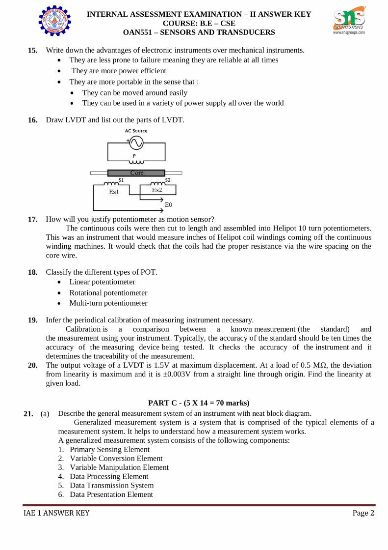
16. Draw LVDT and list out the parts of LVDT.
17. How will you justify potentiometer as motion sensor?
The continuous coils were then cut to length and assembled into Helipot 10 turn potentiometers.
This was an instrument that would measure inches of Helipot coil windings coming off the continuous
winding machines. It would check that the coils had the proper resistance via the wire spacing on the
core wire.
18. Classify the different types of POT.
Linear potentiometer
Rotational potentiometer
Multi-turn potentiometer
19. Infer the periodical calibration of measuring instrument necessary.
Calibration is a comparison between a known measurement (the standard) and
the measurement using your instrument. Typically, the accuracy of the standard should be ten times the
accuracy of the measuring device being tested. It checks the accuracy of the instrument and it
determines the traceability of the measurement.
20. The output voltage of a LVDT is 1.5V at maximum displacement. At a load of 0.5 MΩ, the deviation
from linearity is maximum and it is ±0.003V from a straight line through origin. Find the linearity at
given load.
PART C - (5 X 14 = 70 marks)
21. (a) Describe the general measurement system of an instrument with neat block diagram.
Generalized measurement system is a system that is comprised of the typical elements of a
measurement system. It helps to understand how a measurement system works.
A generalized measurement system consists of the following components:
1. Primary Sensing Element
2. Variable Conversion Element
3. Variable Manipulation Element
4. Data Processing Element
5. Data Transmission System
6. Data Presentation Element
INTERNAL ASSESSMENT EXAMINATION – II ANSWER KEY
COURSE: B.E – CSE
OAN551 – SENSORS AND TRANSDUCERS
IAE 1 ANSWER KEY Page 3
In addition to the above components, a measurement system may also have a data storage
element to store measured data for future use. As the above six components are the most common
ones used in many measurement systems, they are discussed in detail below:
1. Primary Sensing Element:
The primary sensing element receives signal of the physical quantity to be measured as input. It
converts the signal to a suitable form (electrical, mechanical or other form), so that it becomes easier
for other elements of the measurement system, to either convert or manipulate it.
2. Variable Conversion Element:
Variable conversion element converts the output of the primary sensing element to a more suitable
form. It is used only if necessary.
3. Variable Manipulation Element:
Variable manipulation element manipulates and amplifies the output of the variable conversion
element. It also removes noise (if present) in the signal.
4. Data Processing Element:
Data processing element is an important element used in many measurement systems. It processes
the data signal received from the variable manipulation element and produces suitable output.
Data processing element may also be used to compare the measured value with a standard value to
produce required output.
5. Data Transmission System:
Data Transmission System is simply used for transmitting data from one element to another. It acts
as a communication link between different elements of the measurement system. Some of the data
transmission elements used is cables, wireless antennae, transducers, telemetry systems etc.
6. Data Presentation Element:
It is used to present the measured physical quantity in a human readable form to the observer. It
receives processed signal from data processing element and presents the data in a human readable
form. LED displays are most commonly used as data presentation elements in many measurement
INTERNAL ASSESSMENT EXAMINATION – II ANSWER KEY
COURSE: B.E – CSE
OAN551 – SENSORS AND TRANSDUCERS
IAE 1 ANSWER KEY Page 4
systems.
OR
(b) (i) Classify the standards and give example for each level of standard.
Here is a three-level hierarchy of physical measurement standards
Primary standards are made to the highest metrological quality and are the definitive
definition or realization of their unit of measure
The next quality standard in the hierarchy is known as a secondary standard. Secondary
standards are calibrated with reference to a primary standard
The third level of standard, a standard which is periodically calibrated against a secondary
standard, is known as a working standard
Working standards are used for the calibration of commercial and industrial measurement
equipment
Primary Standard:
An example of a primary standard was the international prototype kilogram (IPK) which
was the master kilogram and the primary mass standard for the International System of
Units (SI)
Secondary reference standard:
Secondary reference standards are very close approximations of primary reference
standards
For example, major national measuring laboratories such as the US's National Institute of
Standards and Technology (NIST) will hold several "national standard" kilograms, which
are periodically calibrated against the IPK and each other
Working standard:
A machine shop will have physical working standards (gauge blocks for example) that are
used for checking its measuring instruments
Working standards and certified reference materials used in commerce and industry have a
traceable relationship to the secondary and primary standards
Working standards are expected to deteriorate, and are no longer considered traceable to a
national standard after a time period or use count expires
Laboratory standard:
National organizations provide calibration and private industrial laboratories with items,
processes and/or certification so they can provide certified traceability to national standards
(In the United States, NIST operates the NVLAP program)
These laboratory standards are kept in controlled conditions to maintain their precision,
and used as a reference for calibration and creating working standards
Sometimes they are (incorrectly) called "secondary standards" because of their high quality
and reference suitability
INTERNAL ASSESSMENT EXAMINATION – II ANSWER KEY
COURSE: B.E – CSE
OAN551 – SENSORS AND TRANSDUCERS
IAE 1 ANSWER KEY Page 5
(ii) Elaborate in detail about the statistical methods of error analysis with example.
Accuracy is the closeness of agreement between a measured value and a true or accepted
value. Measurement error is the amount of inaccuracy.
Precision is a measure of how well a result can be determined (without reference to a
theoretical or true value). It is the degree of consistency and agreement among independent
measurements of the same quantity; also the reliability or reproducibility of the result
The uncertainty estimate associated with a measurement should account for both the
accuracy and precision of the measurement
Random errors are statistical fluctuations (in either direction) in the measured data due to
the precision limitations of the measurement device. Random errors can be evaluated
through statistical analysis and can be reduced by averaging over a large number of
observations
Systematic errors are reproducible inaccuracies that are consistently in the same direction.
These errors are difficult to detect and cannot be analyzed statistically
If a systematic error is identified when calibrating against a standard, applying a correction
or correction factor to compensate for the effect can reduce the bias
Unlike random errors, systematic errors cannot be detected or reduced by increasing the
number of observations
Gross personal errors, sometimes called mistakes or blunders, should be avoided and
corrected if discovered. As a rule, personal errors are excluded from the error analysis
discussion because it is generally assumed that the experimental result was obtained by
following correct procedures. The term human error should also be avoided in error
analysis discussions because it is too general to be useful.
The uncertainty of a single measurement is limited by the precision and accuracy of the
measuring instrument, along with any other factors that might affect the ability of the
experimenter to make the measurement.
The number of significant figures implies an approximate relative uncertainty:
1 significant figure suggests a relative uncertainty of about 10% to 100%
2 significant figures suggest a relative uncertainty of about 1% to 10%
3 significant figures suggest a relative uncertainty of about 0.1% to 1%
Type A evaluation of standard uncertainty - method of evaluation of uncertainty by the
statistical analysis of a series of observations. This method primarily
includes random errors.
Type B evaluation of standard uncertainty - method of evaluation of uncertainty by
means other than the statistical analysis of series of observations. This method
includes systematic errors and any other uncertainty factors that the experimenter believes
are important.
22. (a) Briefly explain the categories of sensors.
There are several classifications of sensors made by different authors and experts. Some are
very simple and some are very complex. The following classification of sensors may already be
used by an expert in the subject but this is a very simple classification of sensors.
In the first classification of the sensors, they are divided in to Active and Passive. Active
Sensors are those which require an external excitation signal or a power signal.
Passive Sensors, on the other hand, do not require any external power signal and directly
INTERNAL ASSESSMENT EXAMINATION – II ANSWER KEY
COURSE: B.E – CSE
OAN551 – SENSORS AND TRANSDUCERS
IAE 1 ANSWER KEY Page 6
generates output response.
The other type of classification is based on the means of detection used in the sensor. Some
of the means of detection are Electric, Biological, Chemical, Radioactive etc.
The next classification is based on conversion phenomenon i.e. the input and the output.
Some of the common conversion phenomena are Photoelectric, Thermoelectric,
Electrochemical, Electromagnetic, Thermooptic, etc.
The final classification of the sensors are Analog and Digital Sensors. Analog Sensors
produce an analog output i.e. a continuous output signal with respect to the quantity being
measured.
Digital Sensors, in contrast to Analog Sensors, work with discrete or digital data. The data in
digital sensors, which is used for conversion and transmission, is digital in nature.
Different Types of Sensors
The following is a list of different types of sensors that are commonly used in various applications.
All these sensors are used for measuring one of the physical properties like Temperature,
Resistance, Capacitance, Conduction, Heat Transfer etc.
Temperature Sensor
Proximity Sensor
Accelerometer
IR Sensor (Infrared Sensor)
Pressure Sensor
Light Sensor
Ultrasonic Sensor
Smoke, Gas and Alcohol Sensor
Touch Sensor
Color Sensor
Humidity Sensor
Tilt Sensor
Flow and Level Sensor
(b) Summarize the classification of transducers in detail.
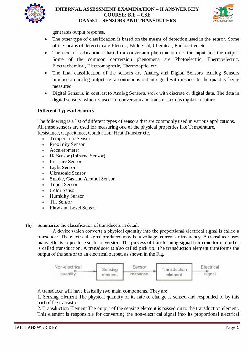
A device which converts a physical quantity into the proportional electrical signal is called a
transducer. The electrical signal produced may be a voltage, current or frequency. A transducer uses
many effects to produce such conversion. The process of transforming signal from one form to other
is called transduction. A transducer is also called pick up. The transduction element transforms the
output of the sensor to an electrical output, as shown in the Fig.
A transducer will have basically two main components. They are
1. Sensing Element The physical quantity or its rate of change is sensed and responded to by this
part of the transistor.
2. Transduction Element The output of the sensing element is passed on to the transduction element.
This element is responsible for converting the non-electrical signal into its proportional electrical
INTERNAL ASSESSMENT EXAMINATION – II ANSWER KEY
COURSE: B.E – CSE
OAN551 – SENSORS AND TRANSDUCERS
IAE 1 ANSWER KEY Page 7
signal.
There may be cases when the transduction element performs the action of both transduction
and sensing. The best example of such a transducer is a thermocouple. A thermocouple is used to
generate a voltage corresponding to the heat that is generated at the junction of two dissimilar
metals.
Classification of Transducers:
The Classification of Transducers is done in many ways. Some of the criteria for the
classification are based on their area of application, Method of energy conversion, Nature of output
signal, According to Electrical principles involved, Electrical parameter used, principle of operation,
& Typical applications. The transducers can be classified broadly,
i. On the basis of transduction form used
ii. As primary and secondary transducers
iii. As active and passive transducers
iv. As transducers and inverse transducers
Resistive Transducers:
1. Resistance Strain Gauge – The change in value of resistance of metal semi-conductor due to
elongation or compression is known by the measurement of torque, displacement or force.
2. Resistance Thermometer – The change in resistance of metal wire due to the change in
temperature known by the measurement of temperature
3. Resistance Hygrometer – The change in the resistance of conductive strip due to the change of
moisture content is known by the value of its corresponding humidity
4. Hot Wire Meter – The change in resistance of a heating element due to convection cooling of a
flow of gas is known by its corresponding gas flow or pressure
5. Photoconductive Cell – The change in resistance of a cell due to a corresponding change in light
flux is known by its corresponding light intensity
6. Thermistor – The change in resistance of a semi-conductor that has a negative co-efficient of
resistance is known by its corresponding measure of temperature
7. Potentiometer Type – The change in resistance of a potentiometer reading due to the movement of
the slider as a part of an external force applied is known by its corresponding pressure or
displacement
Capacitance Transducers:
1. Variable capacitance pressure gage - Principle of operation: Distance between two parallel plates
is varied by an externally applied force Applications: Measurement of Displacement, pressure
2. Capacitor microphone Principle of operation: Sound pressure varies the capacitance between a
fixed plate and a movable diaphragm. Applications: Speech, music, noise
3. Dielectric gauge Principle of operation: Variation in capacitance by changes in the dielectric.
Applications: Liquid level, thickness
Inductance Transducers:
1. Magnetic circuit transducer Principle of operation: Self inductance or mutual inductance of ac-
excited coil is varied by changes in the magnetic circuit. Applications: Pressure, displacement
2. Reluctance pickup Principle of operation: Reluctance of the magnetic circuit is varied by
changing the position of the iron core of a coil. Applications: Pressure, displacement, vibration,
position
3. Differential transformer Principle of operation: The differential voltage of two secondary
windings of a transformer is varied by positioning the magnetic core through an externally
applied force. Applications: Pressure, force, displacement, position
INTERNAL ASSESSMENT EXAMINATION – II ANSWER KEY
COURSE: B.E – CSE
OAN551 – SENSORS AND TRANSDUCERS
IAE 1 ANSWER KEY Page 8
4. Eddy current gage Principle of operation: Inductance of a coil is varied by the proximity of an
eddy current plate. Applications: Displacement, thickness
5. Magnetostriction gauge Principle of operation: Magnetic properties are varied by pressure and
stress. Applications: Force, pressure, sound
Voltage and current Transducers:
1. Hall effect pickup Principle of operation: A potential difference is generated across a
semiconductor plate (germanium) when magnetic flux interacts with an applied current.
Applications: Magnetic flux, current
2. Ionization chamber Principle of operation: Electron flow induced by ionization of gas due to
radioactive radiation. Applications: Particle counting, radiation
3. Photoemissive cell Principle of operation: Electron emission due to incident radiation on
photoemissive surface. Applications: Light and radiation
4. Photomultiplier tube Principle of operation: Secondary electron emission due to incident radiation
on photosensitive cathode.
Applications: Light and radiation, photo-sensitive relays
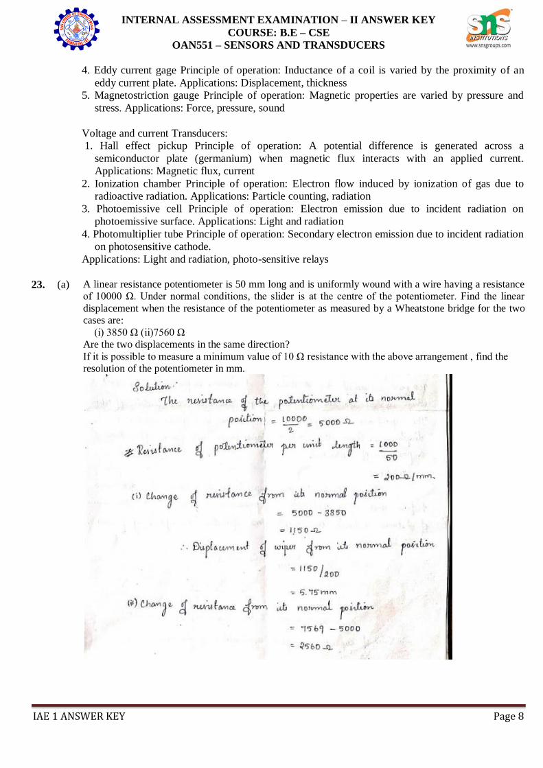
23. (a) A linear resistance potentiometer is 50 mm long and is uniformly wound with a wire having a resistance
of 10000 Ω. Under normal conditions, the slider is at the centre of the potentiometer. Find the linear
displacement when the resistance of the potentiometer as measured by a Wheatstone bridge for the two
cases are:
(i) 3850 Ω (ii)7560 Ω
Are the two displacements in the same direction?
If it is possible to measure a minimum value of 10 Ω resistance with the above arrangement , find the
resolution of the potentiometer in mm.
INTERNAL ASSESSMENT EXAMINATION – II ANSWER KEY
COURSE: B.E – CSE
OAN551 – SENSORS AND TRANSDUCERS
IAE 1 ANSWER KEY Page 9
OR
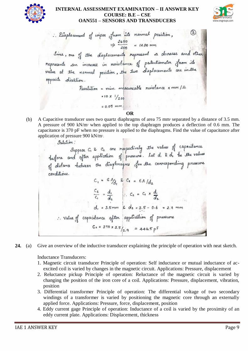
(b) A Capacitive transducer uses two quartz diaphragms of area 75 mm2 separated by a distance of 3.5 mm.
A pressure of 900 kN/m2 when applied to the top diaphragm produces a deflection of 0.6 mm. The
capacitance is 370 pF when no pressure is applied to the diaphragms. Find the value of capacitance after
application of pressure 900 kN/m2.
24. (a) Give an overview of the inductive transducer explaining the principle of operation with neat sketch.
Inductance Transducers:
1. Magnetic circuit transducer Principle of operation: Self inductance or mutual inductance of ac-
excited coil is varied by changes in the magnetic circuit. Applications: Pressure, displacement
2. Reluctance pickup Principle of operation: Reluctance of the magnetic circuit is varied by
changing the position of the iron core of a coil. Applications: Pressure, displacement, vibration,
position
3. Differential transformer Principle of operation: The differential voltage of two secondary
windings of a transformer is varied by positioning the magnetic core through an externally
applied force. Applications: Pressure, force, displacement, position
4. Eddy current gage Principle of operation: Inductance of a coil is varied by the proximity of an
eddy current plate. Applications: Displacement, thickness
INTERNAL ASSESSMENT EXAMINATION – II ANSWER KEY
COURSE: B.E – CSE
OAN551 – SENSORS AND TRANSDUCERS
IAE 1 ANSWER KEY Page 10
5. Magnetostriction gauge Principle of operation: Magnetic properties are varied by pressure and
stress. Applications: Force, pressure, sound
Inductive transducers work on the principle of inductance change due to any appreciable
change in the quantity to be measured i.e. measured.
For example, LVDT, a kind of inductive transducers, measures displacement in terms of
voltage difference between its two secondary voltages.
Secondary voltages are nothing but the result of induction due to the flux change in the
secondary coil with the displacement of the iron bar.
Anyway LVDT is discussed here briefly to explain the principle of inductive transducer.
LVDT will be explained in other article in more detail.
Hence inductive transducers use one of the following principles for its working.
1. Change of self inductance
2. Change of mutual inductance
3. Production of eddy current
OR
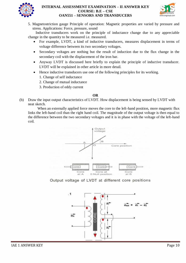
(b) Draw the input output characteristics of LVDT. How displacement is being sensed by LVDT with
neat sketch.
When an externally applied force moves the core to the left-hand position, more magnetic flux
links the left-hand coil than the right hand coil. The magnitude of the output voltage is then equal to
the difference between the two secondary voltages and it is in phase with the voltage of the left-hand
coil.
INTERNAL ASSESSMENT EXAMINATION – II ANSWER KEY
COURSE: B.E – CSE
OAN551 – SENSORS AND TRANSDUCERS
IAE 1 ANSWER KEY Page 11
Now three cases arise according to the locations of core which explains the working of LVDT are
discussed below as,
CASE I When the core is at null position (for no displacement) When the core is at null position
then the flux linking with both the secondary windings is equal so the induced emf is equal
in both the windings. So for no displacement the value of output eout is zero as e1 and e2
both are equal. So it shows that no displacement took place.
CASE II When the core is moved to upward of null position (For displacement to the upward of
reference point) In the this case the flux linking with secondary winding S1 is more as
compared to flux linking with S2. Due to this e1 will be more as that of e2. Due to this
output voltage eout is positive.
CASE III When the core is moved to downward of Null position (for displacement to the downward
of reference point) In this case magnitude of e2 will be more as that of e1. Due to this
output eout will be negative and shows the output to downward of reference point.
Output VS Core Displacement A linear curve shows that output voltage varies linearly with
displacement of core.
Some important points about magnitude and sign of voltage induced in LVDT
The amount of change in voltage either negative or positive is proportional to the amount of
movement of core and indicates amount of linear motion
By noting the output voltage increasing or decreasing the direction of motion can be
determined
The output voltage of an LVDT is linear function of core displacement
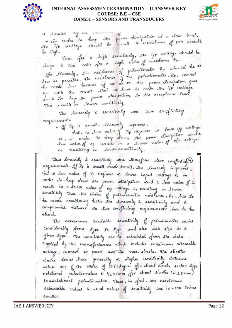
25. (a) Demonstrate the linear and angular displacement of Potentiometer.
INTERNAL ASSESSMENT EXAMINATION – II ANSWER KEY
COURSE: B.E – CSE
OAN551 – SENSORS AND TRANSDUCERS
IAE 1 ANSWER KEY Page 12
INTERNAL ASSESSMENT EXAMINATION – II ANSWER KEY
COURSE: B.E – CSE
OAN551 – SENSORS AND TRANSDUCERS
IAE 1 ANSWER KEY Page 13
OR
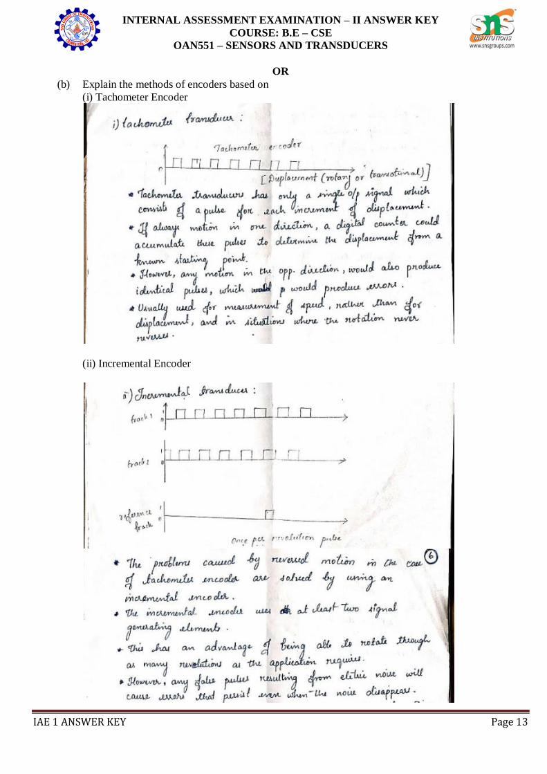
(b) Explain the methods of encoders based on
(i) Tachometer Encoder
(ii) Incremental Encoder
INTERNAL ASSESSMENT EXAMINATION – II ANSWER KEY
COURSE: B.E – CSE
OAN551 – SENSORS AND TRANSDUCERS
IAE 1 ANSWER KEY Page 14
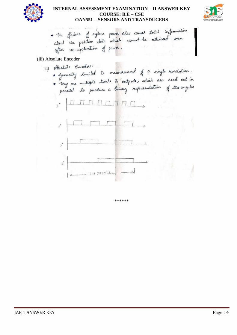
(iii) Absolute Encoder
******
![16 EXAMINATION Model Answer Subject Code: 17213 · PDF fileWINTER– 16 EXAMINATION Model Answer Subject Code: ... [Correct answer- 2 marks] ... satellite communication. 2](https://img.pdfslide.net/doc/110x75/5abe935d7f8b9ac0598d4cf6/16-examination-model-answer-subject-code-17213-16-examination-model-answer-subject.jpg)