Embed Size (px)
Citation preview
Off-shoreInternal Flow-induced Instability Analysis of Catenary Risers K.N. Bakis and N. Srinil
VIII International Conference on Computational Methods in Marine Engineering MARINE 2019
R. Bensow and J. Ringsberg (Eds)
INTERNAL FLOW-INDUCED INSTABILITY ANALYSIS OF CATENARY RISERS
MARINE 2019 KONSTANTINOS N. BAKIS AND NARAKORN SRINIL
Marine, Offshore & Subsea Technology Group, School of Engineering, Newcastle University, Newcastle upon Tyne, NE1 7RU, United Kingdom
[email protected]; [email protected]; www.muffinsproject.org.uk
Key words: Catenary Riser, Internal Flow, Finite Element Method, Instability Analysis
Abstract. Offshore production and export risers in deep-water oil and gas applications are highly slender and flexible cylindrical structures subject to complex environmental and operational loading conditions. In particular, catenary risers having variable curvature have been widely considered by industry as a technologically and economically viable solution for deep waters. Nevertheless, the mechanism of dynamic instability of curved bendable pipes transporting flows has not been properly investigated in the literature despite such practical and theoretical importance. In this study, the dynamic response and stability of catenary risers conveying internal flows are investigated by using a linearized finite element-based continuum pipe model. The governing fluid-structure interaction equations are derived using Hamilton’s principle and formatted into a generalized eigenvalue form in order to assess its stability for varying internal flow speeds. This procedure elucidates the contribution of the Centrifugal and Coriolis related terms for the onset of divergence and flutter unstable modes. It is shown that the pipe’s tension to bending rigidity ratio plays a catalytic role in the occurrence and evolution of intermodal coupling of the flutter modes in post-divergence regime. Theories and numerical strategies present in this study are being extended to the multiphase flow-induced vibration applications. 1 INTRODUCTION
Marine risers are widely used for offshore oil and gas transportation in deep waters and their operability has a direct impact on the life cycle and economics of the field. Because of its inherent flexibility and tight horizontal offset constraints, the riser comprises the most sensitive component within the oil and gas extraction system. It is therefore that the subject of understanding the riser’s linear or nonlinear dynamic response has attracted the interest of the scientific community.
A marine riser, transporting crude oil and natural gas is simply supported at normal operation conditions. The dynamics of a pinned-pinned configuration has been extensively studied with regard to external loading and the basic mechanism of vortex induced vibrations (VIVs) is well documented in the literature [1]. In that regard various numerical [2] and computational [3] investigations have been performed in the past two decades. The dynamic response of a flexible riser due to internal single-phase flows has been formulated using
525
Konstantinos N. Bakis, Narakorn Srinil
2
different approaches for planar vibrations, see Semler et al. [4] and Lin et al. [5], while there are also works focusing on the 3D dynamic response behavior [6].
Deep-water ocean exploration expansion constantly demands for longer and slenderer risers, which inherently exhibit new dynamic features [7, 8]. A different modeling methodology is based on elastica theory. The extensible elastica has been well established in previous works [9, 10]. Moreover, the fluid plug flow model has been extended to include the effect of pulsatile flow-induced vibrations [11,12,13,14]. Extensibility effects have been highlighted by Chucheepsakul et al. [15] and Monprappusorn et al. [11].
Dynamic response attributed to internal slug flows in subsea piping systems is quickly becoming an issue of increasing concern due to its role in fatigue related failures. The slug flow regime potentially generates more pronounced structural vibrations due to the fluctuation of density, velocity and pressure of the transported fluid mixture [16]. Patel and Seyed [17] were among the first to formulate the mathematical expressions for the time-varying flow in a flexible riser in the 2-D plane. Their model, however, was a simplified version of internal slug flow excluding a lot of the fluid-structure complexity. It is only recently that the importance of slug flows to the riser dynamics has been appreciated in the academic community [18,19]. So far investigations have demonstrated that slug flows give rise to increased normal and axial responses contributing to higher dynamic tension, curvature and bending stresses. Further experimental and analytical works should be carried out to better understand the dynamic interaction of internal and external flow on a flexible catenary pipe as well as other operational impacts.
The aim of this fundamental work is to make use of a finite element formulation for modeling the effects of single-phase flow on the stability boundaries and dynamic response of deep-water catenary pipes. The current work is the initial stage for incorporating the full 3D nonlinear behavior of a flexible liquid-conveying pipe while subjected to space-time varying external flow excitations. Previous research on the stability limits of pipes [20,21] has focused on simple straight pipe configurations either pinned-pinned or cantilevered. It is believed by the authors that the nature and stability mechanism of a flexible riser with varying curvature has been neglected in the literature. Consequently, this paper will focus on the investigation of different patterns of instability which influence the behavior of the stability limits by formulating the catenary pipe dynamics using a new procedure.
2 MODELING PROCESS
2.1 Static configuration of catenary risers The riser is considered to be a flexural sagged cable-like elastic structure and its planar
configuration only due to the effective self-weight is considered here for convenience. Bending rigidity is neglected for the static analysis but considered for the vibrational response from the equilibrium position. The static profile of an SCR (steel catenary riser) is governed by the catenary configuration given by Equation [1]. This is a plausible simplification because of the pinned connections at the boundaries and due to the fact that SCR curvatures are relatively small [2].
526
Konstantinos N. Bakis, Narakorn Srinil
3
22
2 1
E
w
Wd y dydx H dx
(1)
EW is the computed effective weight accounting for the weight of the riser in air, the buoyancy of the riser element, the weight of the internal flow and the added mass effect of the pipe surrounding sea-water. wH is the horizontal component of the riser tension which is spatially constant. Integrating Equation (1) twice and applying appropriate boundary conditions the static riser shape is obtained. The corresponding riser tension, neglecting the shear component, can also be derived accordingly [22]. Thus, for given EW , wH and specified horizontal and vertical pipe projections H HX ,Y , the total length, catenary geometry and static tension along the pipe is straight forwardly determined. Current flow forces on the pipe are neglected in this work as the focus lies in the internal flow-induced vibrations.
2.2 Fluid-pipe dynamic equations Consider a straight-pipe element subject to small amplitude vibrations. A generic pipe-
fluid element has axial and transverse displacements u( x,t ) and w( x,t ), respectively. Let the distance measured along the pipe’s local coordinate system be x , while the vertical coordinate be z . As the fluid flows along the curve described by the centerline, its motion is affected by the vertical acceleration, angular acceleration and changing curvature. An element of fluid being transported along the pipe has constant velocity U tangent to the pipe axis and velocity
ww t in the vertical direction. For a general pipe planar configuration, the
velocity of the center of a fluid element along the curvilinear coordinate s is given by the following expression [20]:
frV i k
DU x zt s Dt
(2)
where, r is the position vector to a point measured from the origin and DDt
is the
material derivative of the fluid element. Assuming that the curvilinear pipe is modeled using inter-connecting straight elements, the kinetic energy of the fluid of a straight segment of length L in the local coordinate system can be written as:
2 2
02f
f
Lm u u w wT U U dxt x t x
(3)
The kinetic energy of the pipe is simply given by:
2 2
02
Lp
p
mT u w dx (4)
where, fm is per unit length mass of the fluid and pm is the mass density of the pipeline,
527
Konstantinos N. Bakis, Narakorn Srinil
4
respectively. The upper dash denotes the local system in the orientation of the individual straight element. The potential energy of a straight pipe segment because of bending, axial strain and tension is given by the following formula [21]:
2 2
0 0
1 12 2
L L
p T x pU = EA dx EI w dx (5)
where,
21
2, T x
p
T u uEA
(6)
The overdot and prime denote the derivatives with respect to time t and local spatial coordinate x , respectively. Substituting Equation (6) to (5) and neglecting some higher order terms we get the expression:
2 2 2
0 0
1 122 2
L L
p pU = T u u EA u dx EI w dx (7)
p pA ,I are the second moment of area and the mass density of the pipeline, respectively.
2.3 Effect of cable tension on the system dynamics In this work the contribution of cable tension on the dynamic equations of motion is
considered by referring to Ghaffar’s formulation [23] for a uniform section cable under uniform loading. The model stays within linear theory by considering small displacements from the position of the static catenary equilibrium. The analysis restricts its attention to small vibration response in the vertical plane. Let wH be the horizontal component of cable tension given by the equations of the catenary configuration [22]. H(t) is the cable tension caused by inertia forces. It is assumed that H(t) is small compared to wH or w wH + H(t) H . Vibration damping of the structure is neglected at this stage.
As a result of small, free vibrations about the position of static equilibrium, the horizontal component of tension, wH will change to wH + H(t) and the differential length of the cable ds will increase to ds ds . The potential energy of the cable element is then expressed as:
( )
t w EdsdU = H H t ds W w dsdx
(8)
where ds is the pipe stretch of the differential length ds and w is the vertical vibrational displacement in the direction of gravity. The first term in Equation (8) is the strain energy
stored in the element ds and is equal to the average force
w1 dsH + H(t)2 dx
times the pipe
stretch ds . The factor 12
is needed due to the fact that H(t) increases from zero to its
maximum value and dsdx
is the cosine of the inclination angle. The second term represents the
gravity energy, i.e., the potential energy loss due to the lowered position of the effective load. Integrating Equation (8) and following several differential calculus manipulations leads to the
528
Konstantinos N. Bakis, Narakorn Srinil
5
following equation:
2
0 0
12
H H H2X X X
t w0
1 w w y wU (t)= H dx+ H(t) dx dx2 t x x x
(9)
To bring Equation (9) in a more convenient form, we make use of the cable equation which relates the stretching of the cable element to the geometric displacements which it undergoes [24]:
2
0 0
12
( ) H HX X
e
p
H t L w y w= dx dxEA x x x
(10)
0
HX
3
edsL dxdx
is the virtual length of the cable. Equation (9) then becomes:
2 2
0
1 12 2
( ) HX
et w
p
H t LwU (t)= H dxt EA
(11)
The second term of the above equation expresses that part of potential energy stored elastically in the cable, i.e. strain energy of the cable. The first term containing the constant
wH represents the potential energy resulting from the elevation of the cable. In this analysis the cable is considered deformable but inextensible.
The differential equations of motion for catenary riser as well as the correct number of boundary conditions can be derived using Hamilton’s principle given by the integral form:
2
1
0( ) t
t
T U W (12)
The total virtual work W by the flow induced forces is zero because these have been considered in the terms for the kinetic energy of the fluid. The resulting equations of motion are:
4 2 2 2 2
24 2 2 22 0( )
E
p f w f f pw
Ww w w w wEI m U H H t m U m mx x x H x t t
(13)
where, 2
0 0
12
( )
H HX Xp
e
EA w dy wH t dx dxL x dx x
(14)
and in the axial direction,
2 2 2 2
22 2 22 0
p f f p f
u u u uEA T m U m U m mx x x t t
(15)
In Equation (13) the cable tension stiffness contribution is considered in the global w
coordinate, while the rest is in the element local coordinate w . The above methodology takes into account the static stress as well as the effect of vibrational change of riser tension and consequently the finite element eigenvalue analysis to follow determines more accurately the riser’s modal characteristics.
529
Konstantinos N. Bakis, Narakorn Srinil
6
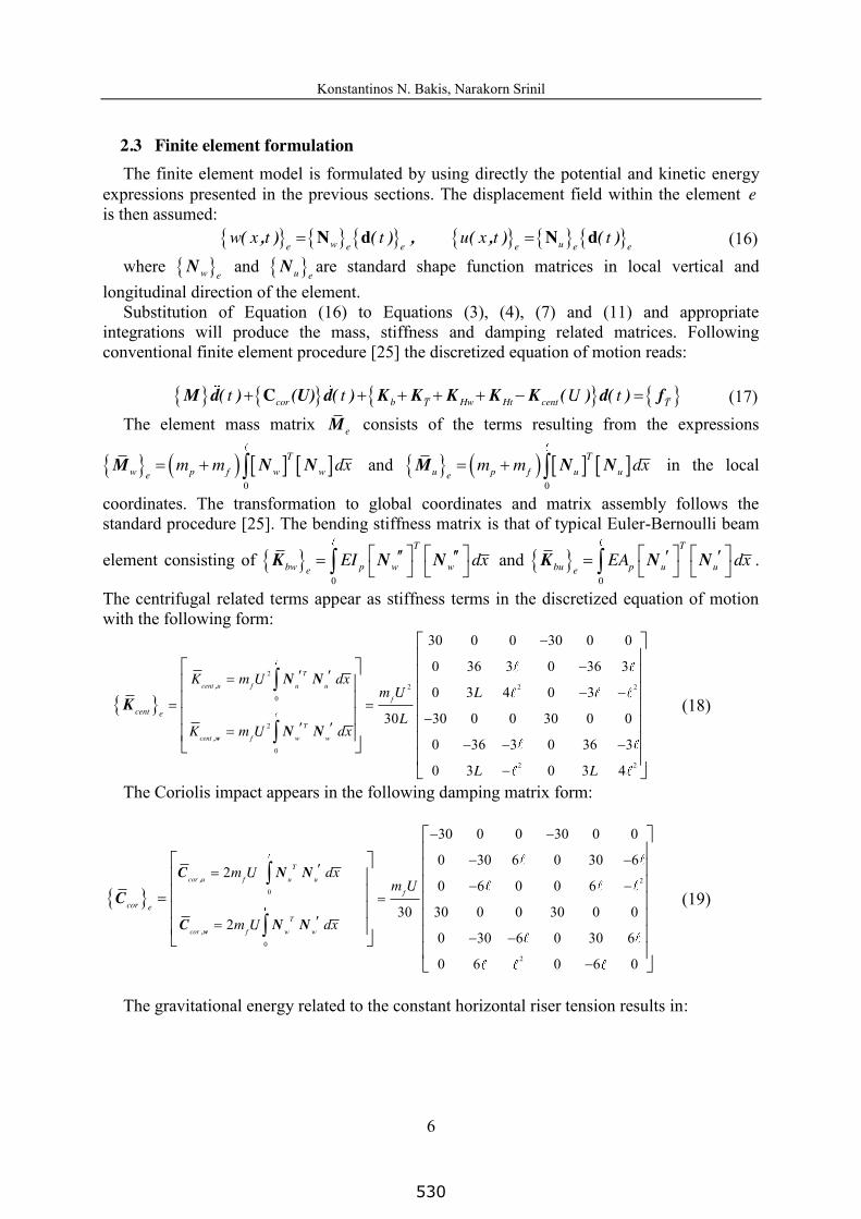
2.3 Finite element formulation The finite element model is formulated by using directly the potential and kinetic energy
expressions presented in the previous sections. The displacement field within the element e is then assumed:
N d N d( , ) ( ) , ( , ) ( ) w ue e e e e ew x t t u x t t (16)
where Nw e and Nu e
are standard shape function matrices in local vertical and longitudinal direction of the element.
Substitution of Equation (16) to Equations (3), (4), (7) and (11) and appropriate integrations will produce the mass, stiffness and damping related matrices. Following conventional finite element procedure [25] the discretized equation of motion reads:
CM d( ) (U) d( ) K K K K K ( ) d( ) f cor b Hw Ht centT Tt t U t (17) The element mass matrix Me consists of the terms resulting from the expressions
0
M N N T
w p f w wem m dx and
0
M N N T
u p f u uem m dx in the local
coordinates. The transformation to global coordinates and matrix assembly follows the standard procedure [25]. The bending stiffness matrix is that of typical Euler-Bernoulli beam
element consisting of 0
K N N
T
bw p w weEI dx and
0
K N N
T
bu p u ueEA dx .
The centrifugal related terms appear as stiffness terms in the discretized equation of motion with the following form:
2
2 2 20
2
0
2 2
30 0 0 30 0 0
0 36 3 0 36 3
0 3 4 0 3
30 30 0 0 30 0 0
0 36 3 0 36 3
0 3 0 3 4
,
,w
N N
N N
K
T
cent u f u u
f
T
cent f w w
cent e
K m U dxm U L
LK m U dx
L L
(18)
The Coriolis impact appears in the following damping matrix form:
2
0
0
2
30 0 0 30 0 0
0 30 6 0 30 62
0 6 0 0 6
30 30 0 0 30 0 02
0 30 6 0 30 6
0 6 0 6 0
,
,w
C N N
C N N
C
T
cor u f u u
f
T
cor f w w
cor e
m U dxm U
m U dx
(19)
The gravitational energy related to the constant horizontal riser tension results in:
530
Konstantinos N. Bakis, Narakorn Srinil
7
2 2
0
2 2
0 0 0 0 0 0
0 36 3 0 36 3
0 3 4 0 3
0 0 0 0 0 030
0 36 3 0 36 3
0 3 0 3 4
Kx
x x
Lx x x xT w
Hw w w we
x
x x
x x x x
L L
L L L LHH N N dx
L
L L
L L L L
(20)
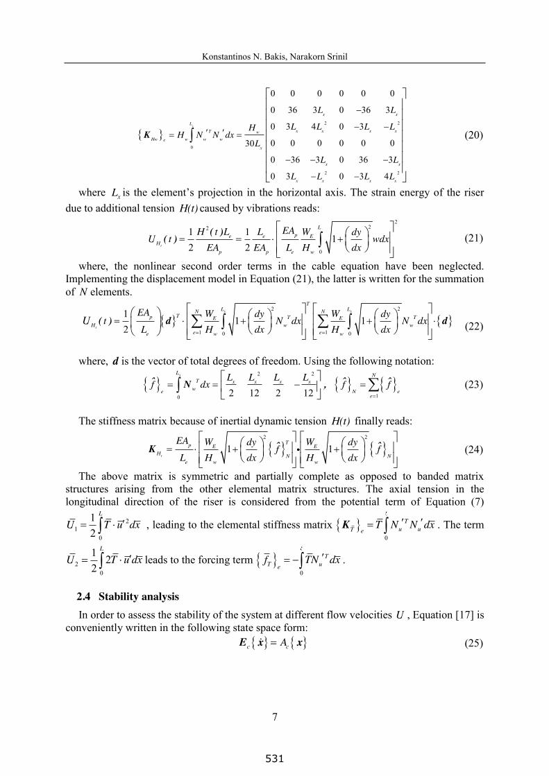
where xL is the element’s projection in the horizontal axis. The strain energy of the riser due to additional tension H(t) caused by vibrations reads:
222
0
1 11
2 2( )
( )t
Lpe e E
Hp p e w
EAH t L L W dyU t wdx
EA EA L H dx
(21)
where, the nonlinear second order terms in the cable equation have been neglected. Implementing the displacement model in Equation (21), the latter is written for the summation of N elements.
2 2
1 10 0
11 1
2( ) d d
x x
t
TL LN N
Tp T TE EH w w
e ee w w
EA W Wdy dyt N dx N dx
L H dx H dxU
(22)
where, d is the vector of total degrees of freedom. Using the following notation:
2 2
10 2 12 2 12ˆ ˆ ˆN ,
xL NT x x x x
we N ee
L L L Lf dx f f
(23)
The stiffness matrix because of inertial dynamic tension H(t) finally reads:
2 2
1 1ˆ ˆKt
Tp E EH N N
e w w
EA W Wdy dyf f
L H dx H dx
(24)
The above matrix is symmetric and partially complete as opposed to banded matrix structures arising from the other elemental matrix structures. The axial tension in the longitudinal direction of the riser is considered from the potential term of Equation (7)
21
0
12
L
U T u dx , leading to the elemental stiffness matrix 0
K Tu uT e
T N N dx . The term
20
1 22
L
U T u dx leads to the forcing term 0
TT ue
f TN dx .
2.4 Stability analysis In order to assess the stability of the system at different flow velocities U , Equation [17] is
conveniently written in the following state space form: E x xc cA (25)
531
Konstantinos N. Bakis, Narakorn Srinil
8
where, x d,d is the state vector and:
K K K K K ( ) 0C ( ) C M
E ,I 0 0 I
w tb T H H centcor dc c
UUA
(26)
A small amount of structural damping is assumed in the form of a Rayleigh damping matrixC M K d M Ka a . The stability of the system is assessed by plotting the complex eigenvalues of Equation (25) for increasing flow velocities. When the real part of an eigenvalue becomes positive the system loses stability in the linear sense. Two types of instabilities are possible in this case. A divergent type which is reached when the overall stiffness becomes null, and a flutter type instability caused by the coupling of two or more modes at a specific frequency also related to negative damping terms [26, 27].
3 SIMULATION RESULTS
3.1 Application of stability analysis on a long catenary riser
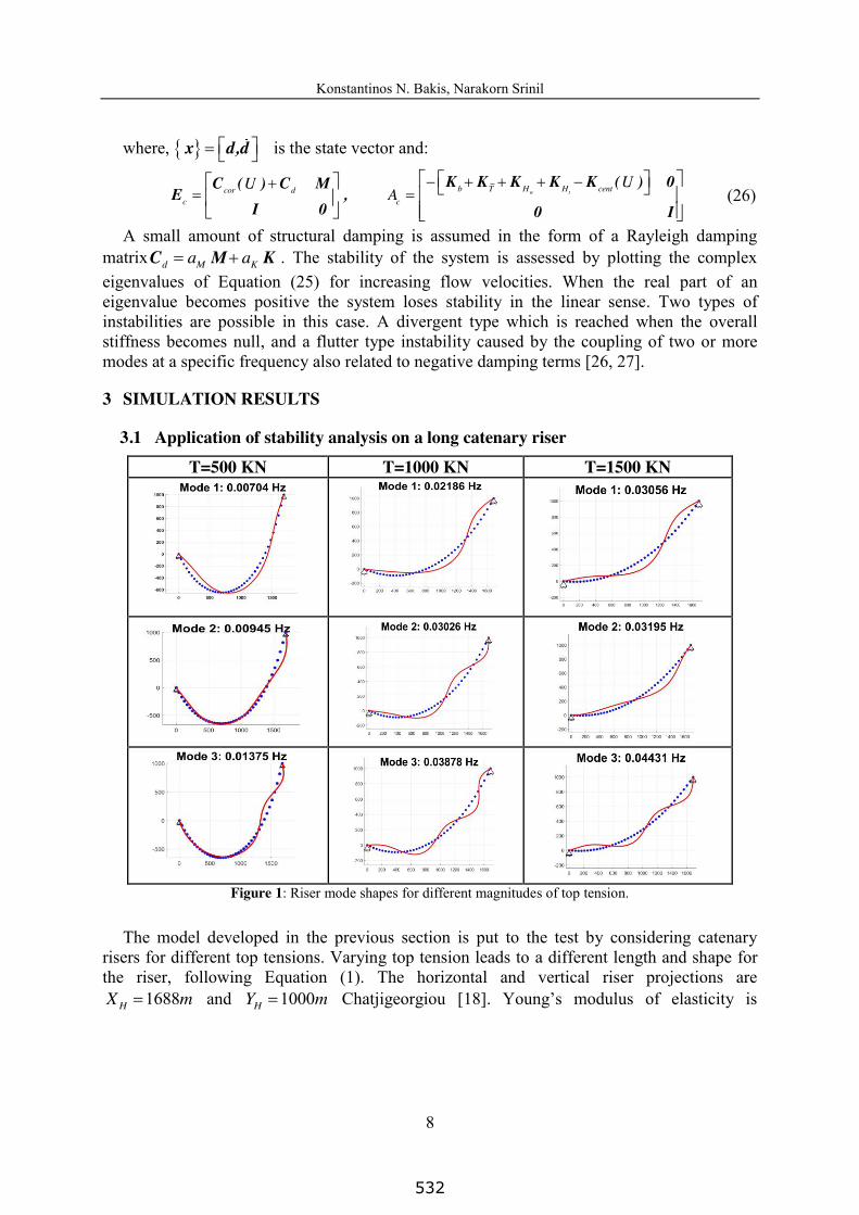
T=500 KN T=1000 KN T=1500 KN
Figure 1: Riser mode shapes for different magnitudes of top tension.
The model developed in the previous section is put to the test by considering catenary risers for different top tensions. Varying top tension leads to a different length and shape for the riser, following Equation (1). The horizontal and vertical riser projections are
1688HX m and 1000HY m Chatjigeorgiou [18]. Young’s modulus of elasticity is
532
Konstantinos N. Bakis, Narakorn Srinil
9
207E GPa while the inner and outer pipe diameters are 0 385.iD m and 0 429.oD m , respectively. The pipe mass is 219 4. /pm kg m and added mass 148 16. /am kg m while the submerged weight is 699 /EW N m . The elastic stiffness pEA and flexural rigidity pEA are
equal to 95 83 10. N and 8 21 209 10. Nm . At static position the pipe is assumed empty. Fig. 1 presents the first three modes for zero internal flow for three different top tension values. The initial static configuration of the catenary is shown in the dotted blue curve.
By solving Equation [25] for increasing flow speed U the system’s complex eigenvalues
are obtained. The dimensionless frequency is related to the corresponding eigenvalue by
the expressions 2( )p iH
p
m mRe( ) imag X
EI
, 2( )p i
Hp
m mIm( ) Re X
EI
[20].
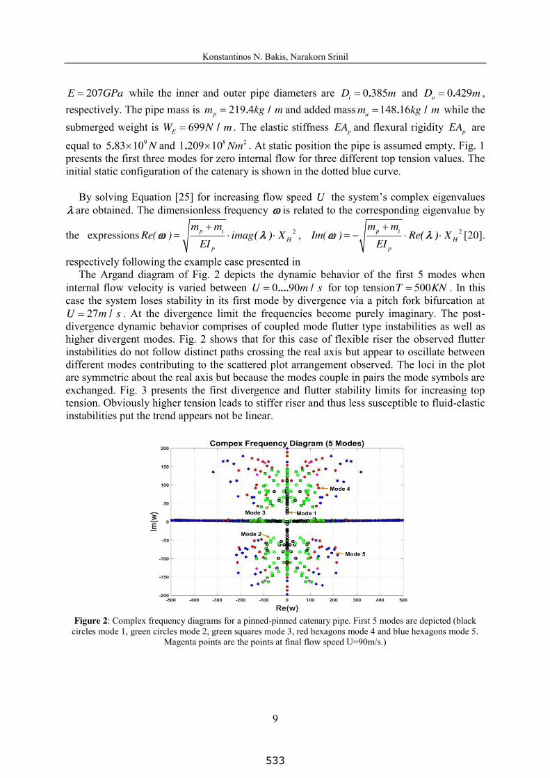
respectively following the example case presented in The Argand diagram of Fig. 2 depicts the dynamic behavior of the first 5 modes when
internal flow velocity is varied between 0 90.... /U m s for top tension 500T KN . In this case the system loses stability in its first mode by divergence via a pitch fork bifurcation at
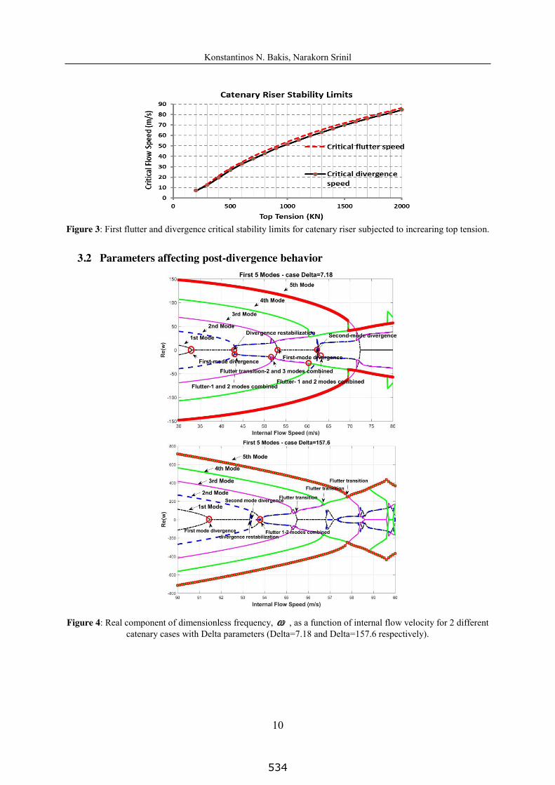
27 /U m s . At the divergence limit the frequencies become purely imaginary. The post-divergence dynamic behavior comprises of coupled mode flutter type instabilities as well as higher divergent modes. Fig. 2 shows that for this case of flexible riser the observed flutter instabilities do not follow distinct paths crossing the real axis but appear to oscillate between different modes contributing to the scattered plot arrangement observed. The loci in the plot are symmetric about the real axis but because the modes couple in pairs the mode symbols are exchanged. Fig. 3 presents the first divergence and flutter stability limits for increasing top tension. Obviously higher tension leads to stiffer riser and thus less susceptible to fluid-elastic instabilities put the trend appears not be linear.
Figure 2: Complex frequency diagrams for a pinned-pinned catenary pipe. First 5 modes are depicted (black
circles mode 1, green circles mode 2, green squares mode 3, red hexagons mode 4 and blue hexagons mode 5. Magenta points are the points at final flow speed U=90m/s.)
533
Konstantinos N. Bakis, Narakorn Srinil
10
Figure 3: First flutter and divergence critical stability limits for catenary riser subjected to increaring top tension.
3.2 Parameters affecting post-divergence behavior
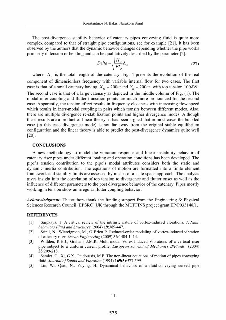
Figure 4: Real component of dimensionless frequency, , as a function of internal flow velocity for 2 different catenary cases with Delta parameters (Delta=7.18 and Delta=157.6 respectively).
534
Konstantinos N. Bakis, Narakorn Srinil
11
The post-divergence stability behavior of catenary pipes conveying fluid is quite more complex compared to that of straight pipe configurations, see for example [21]. It has been observed by the authors that the dynamic behavior changes depending whether the pipe works primarily in tension or bending and can be qualitatively described by the parameter [2].
wp
p
HDeltaEI
(27)
where, p is the total length of the catenary. Fig. 4 presents the evolution of the real component of dimensionless frequency with variable internal flow for two cases. The first case is that of a small catenary having 200HX m and 200HY m , with top tension 100KN . The second case is that of a large catenary as depicted in the middle column of Fig. (1). The modal inter-coupling and flutter transition points are much more pronounced for the second case. Apparently, the tension effect results in frequency closeness with increasing flow speed which results in inter-modal coupling in pairs which transits between different modes. Also, there are multiple divergence re-stabilization points and higher divergence modes. Although these results are a product of linear theory, it has been argued that in most cases the buckled case (in this case divergence mode) is not far away from the original stable equilibrium configuration and the linear theory is able to predict the post-divergence dynamics quite well [20].
CONCLUSIONS A new methodology to model the vibration response and linear instability behavior of
catenary riser pipes under different loading and operation conditions has been developed. The pipe’s tension contribution to the pipe’s modal attributes considers both the static and dynamic inertia contribution. The equations of motion are formatted into a finite element framework and stability limits are assessed by means of a state space approach. The analysis gives insight into the correlation of top tension to divergence and flutter onset as well as the influence of different parameters to the post divergence behavior of the catenary. Pipes mostly working in tension show an irregular flutter coupling behavior.
Acknowledgment: The authors thank the funding support from the Engineering & Physical Sciences Research Council (EPSRC) UK through the MUFFINS project grant EP/P033148/1.
REFERENCES [1] Sarpkaya, T. A critical review of the intrinsic nature of vortex-induced vibrations. J. Num.
behaviors Fluid and Structures (2004) 19:389-447. [2] Srinil, N., Wiercigroch, M., O’Brien P. Reduced-order modeling of vortex-induced vibration
of catenary riser. Ocean Engineering (2009) 36:1404-1414. [3] Willden, R.H.J., Graham, J.M.R. Multi-modal Vorex-Induced Vibrations of a vertical riser
pipe subject to a uniform current profile. European Journal of Mechanics B/Fluids (2004) 23:209-218.
[4] Semler, C., Xi, G.X., Paidoussis, M.P. The non-linear equations of motion of pipes conveying fluid. Journal of Sound and Vibration (1994) 169(5):577-599.
[5] Lin, W., Qiao, N., Yuying, H. Dynamical behaviors of a fluid-conveying curved pipe
535
Konstantinos N. Bakis, Narakorn Srinil
12
subjected to motion constraints and harmonic excitation. Journal of Sound and Vibration (2007) 306:955-967.
[6] Chatjigeorgiou, I.K. On the effect of internal flow on vibrating catenary risers in three dimensions. Engineering Structures (2010) 32:3313-3329.
[7] Meng, S., Kajiwara, H., Zhang, W. Internal flow effect on the cross-flow vortex-induced vibration of a cantilevered pipe discharging fluid. Ocean Engineering (2017) 137:120-128.
[8] Atadan, A.S., Calisal, S.M., Modi, V.J., Guo, Y. Analytical and numerical analysis of the dynamics of a marine riser connected to a floating platform. Ocean Engineering (1997) 24:111-131.
[9] Antman, S.S. Nonlinear Problems of Elasticity. Springer, New York, (1995). [10] Kim, H.T., O’Reilley, O.M. Instability of catenary-type flexible risers conveying fluid in subsea
environments. Ocean Engineering (2019) 173:98-115. [11] Monprapussorn, T., Athisakul, C., Chucheepsakul, S. Nonlinear vibrations of an extensible
flexible marine rise carrying pulsatile flow. Transactions of the ASME (2007) 74:754-769. [12] Ginsberg, J.H. The dynamic stability of a pipe conveying a pulsatile flow. Int. J. Eng. Sci.
(1973) 11:1013-1024. [13] Seo, J.S., Jeong, W.B., Jeong, S.H., Oh, J.S., Yoo, W.S. Finite element analysis of forced
vibration of a pipe conveying harmonically pulsating fluid. JSME International Journal (2005) 48:688-694.
[14] Gorman, D.G., Reese, J.M., Zhang, Y.L. Vibration of a flexible pipe conveying viscous pulsating fluid flow. Journal Sound Vibration (2010) 230:379-392.
[15] Chucheepsakul, T., Monprapussorn, T., Huang, T. Large strain formulations of extensible marine pipes transporting fluid. Journal Fluid Structures (2003) 17:185-224.
[16] Ma, B., Srinil, N. Dynamic characteristics of deep-water risers carrying multiphase flows. ASME 2018 37th International Conference on Ocean, Offshore and Artic Engineering OMAE 2018, June 17-22, Madrid, Spain.
[17] Seyed, F.B., Patel, M.H. Mathematics of flexible risers including pressure and internal flow effects. Marine Structures (1992) 5:121-150.
[18] Chatjigeorgiou, I.K. Hydro-elastic response of marine risers subjected to internal slug-flow. Applied Ocean Research (2017) 62:1-17.
[19] Ortega, A., Rivera, A., Larsen, C.M. Slug flow and waves induced motions in flexible risers. Journal of Offshore Mechanics and Artic Engineering (2018) 140:1-9.
[20] M.P. Paidoussis, Fluid-Structure Interactions: Slender Structures and Axial Flow. Vol. 1, Academic Press Limited, London, 1998.
[21] Lee, U., Park, J. Spectral element modeling and analysis of a pipeline conveying internal unsteady fluid. Journal of Fluids and Structures (2006) 22:273-292.
[22] Cella, P. Methodology for exact solution of catenary. Journal of Structural Engineering (1999) 125(12):1451-1453.
[23] Abdel-Ghaffar, A. Free vertical vibrations of suspension bridges. J. Struct. Div. ASCE 105(ST10) (1980) 2053-2076.
[24] Irvine, H.M. Studies in the statics and dynamics of simple cable systems. California Institute of Technology, Technical report, 1974.
[25] J.H. Prevost, S. Bagrianski, An introduction to matrix structural analysis and finite element methods. World Scientific Publishing, 2017.
[26] Bakis, K.N., Massaro, M., Williams M.S., Limebeer, D.J.N. Aeroelastic control of long-span suspension bridges with controllable winglets. Structural Control and Health Monitoring (2016) 23(12):1417-1441.
[27] Paidoussis, M.P., Issid, N.T. Dynamic stability of pipes conveying fluid. Journal of Sound and Vibration (1974) 33(3):267-294.
536

![Allee-Effect-Induced Instability in a Reaction-Diffusion ... · 2 AbstractandAppliedAnalysis interactionmodelwithlogisticgrowthrateofthepreyinthe absenceofpredationisofthefollowingform[28,29]:](https://img.pdfslide.net/doc/110x75/5f7053b5c407663d222da508/allee-effect-induced-instability-in-a-reaction-diffusion-2-abstractandappliedanalysis.jpg)