Embed Size (px)
Citation preview
Internal Standard Briefing Note
Page 1 of 3 Issue 5 August 2019
Issue Details
Procedure Ref: PE326
Title: Vehicular Plant and Crane Operations
Issue Number: 5
NO CHANGE TO MAIN PROCEDURE.
Addition of Appendix E – Piling and update of forms only.
Issue Date: 15/08/2019
Procedure Owner: Jack Pendle, Engineering Director / Steve Shields, Business Manager Plant
For the attention of
The following roles have specific responsibilities within this procedure and should receive a formal briefing. Records should be retained using Form SAF03F01 – Brief Cascade Record Form.
Role Business
Project Managers All
Lifting Operations Planners All
Crane Supervisors / Crane Controllers All
Purpose
The purpose of this procedure is to:
a) Detail the specific arrangements necessary to manage the safe and efficient organisation and control ofvehicular plant & cranes used or hired by VolkerRail within a specific worksite.
b) Mandate compliance with the requirements of the Provision and use of work Equipment Regulations(PUWER) and the Lifting Operations and Lifting Equipment Regulations (LOLER).
c) Underpin the requirements of element 9.36 of the company’s integrated management system so as tomaintain VolkerRail’s Rail Plant Operating Licence.
Scope and Implementation
This procedure applies to all vehicular plant and cranes, including the organisation and control of vehicle travel movements and lifting operations whether internally or externally contracted, or supplied as part of a contract.
Where VolkerRail is operating on sites under the control of third parties, or in joint venture with other companies then this procedure is the minimum standard which will apply. Machines and equipment within the scope of this documentation include:
Trucks, Dumpers, Dozers, Tractors, Rollers, Road Surface Preparation Machines
Those machine and lifting equipment configurations deemed to be a Crane, such as TelescopicMobile & Crawler Cranes and Tower Cranes as well as MEWPS, Lorry Loaders, Fork Lift Trucks andTele-handlers
Any other machines defined as ‘self-propelled’ and/or machines, accessories or attachments includedwithin the definitions of lifting equipment set out in the Lifting Operations and Lifting EquipmentRegulations, (LOLER)
On-Track Plant and Crane Controlled On-Track Machines

Internal Standard Briefing Note
Page 2 of 3 Issue 5 August 2019
Summary of Changes
Appendices
Appendix G – Carrying out Piling operations
Site Specific Machine Work Plans / Forms amended to reflect new VRCC telephone number
Form PE326F01 Site Specific Machine Work Plan – Parts 1-4
Form PE326F05 OTP and Controlled OTM - CC & TL - Crane Lift Plans - Part 5
Form PE326F06 Tele-handler, Fork Lift Truck & Lorry Loader Crane Lift Plans – Part 6
Form PE326F07 MEWP Operation – Part 7
Form PE326F08 Machine and Crane Controllers Checklist – Part 8
Amendment to form PE326F08 to reflect changes, to comply with wording on official NR form 027 and additional VR required items.
Changes:
M3 If you are the responsible for the safety of people on the track have you carried out the safety briefing in accordance with the Infrastructure Manager’s requirements? or If you are not the responsible person have you and the work group received the briefing from the person responsible?
M4 Have you briefed the operator on the requirements of the work and the factors that may influence the work within the Method Statement (including communication arrangements and defined hazards such as ALO (Any Line Open), weather conditions, gradients and/or contaminated rails that the machine will be working on, and the likely effect these hazards may have on machine operation and any required mitigation measures)?
M5 Have all the relevant staff been briefed not to travel on Machines and Trailers except where authorised on the Engineering Conformance Certificate, Method Statement (incl. Operational Plan, WPP, Task Briefing etc as appropriate)
M7 Do you have suitable arrangements in place to tackle emergency situations e.g. (Firefighting equipment, spill kits, recovery of OTP & personnel and emergency contact information etc.)?
M8 Do you have immediate access to the appropriate protection equipment (e.g. fog signals, Flags, etc.) in accordance with the Rule Book requirements?
M10 Are planned Possession and Protection arrangements adequate for the operations planned for the protection of the site (including protection of the site, adjacent lines and level crossings where applicable)?
M11 Are all third parties overhead cables (e.g. National Grid, telephone) suitably identified and marked by Goal Posts etc, if required by the Method Statement? (Note: if not required or no cables circle N/A)
M12 Are side and overhead clearances sufficient to undertake the work safely and are appropriate arrangements in place for this?
M14 Has the Operator completed the machine specific pre-start functional and operational tests on the machinery? (including Trailers and attachments), and is satisfied that it is safe to use? (eg Lights, Horns, Tyres, Wheels, Hoses, Brakes in order as applicable)?).
M16 Have movement limiting devices (MLD) (height and slew) been set and secured as required? (If not required circle N/A)
M20 For access equipment, has the combined weight of all persons, tools and materials to be carried within the work platform been assessed and documented to determine if they are within the SWL of the machine? (if no access equipment is in use circle N/A).
M21 For access equipment have you established that a Load Calculation Plan has been produced for the machine being used? (if no access equipment is in use circle N/A).
M22 Has a Machine Controller & operator’s approved communication system been set up and tested for use in accordance with the planned arrangements?

Internal Standard Briefing Note
Page 3 of 3 Issue 5 August 2019
Additions:
M6 Where used are the Trailer(s)/attachment(s) compatible with the Host Machine and the maintenance brake test in date? (Note: if not being used tick N/A)
M14a Where a Quick Hitch is fitted: has the Operator established the type of Quick Hitch and have you verified that any safety locks are working correctly and ensured that any necessary Safety Bar is in place?
M17 Does the site specific risk documentation include infrastructure that could cause a wide wheeled RRV to derail? If yes, have you checked to ensure that the RRV does not have wide wheels?
M18 Have you established with the Machine operator, the requirement for him to undertake a close visual inspection (not from the cab) of the quick-hitch and undertake a shakedown test, each time something is attached?
M19 Have you briefed the operator on the conditions and information on the permit to dig prior to any excavating operations which is required? (If not required tick N/A)
VolkerRail Standard PE326 Issue: 5 Date: 15/08/2019
Vehicular Plant and Crane Operations Page: 1 of 29
Vehicular Plant and Crane Operations
Author
Approved by /
Jack Pendle, Engineering Director / Stuart Webster-Spriggs, HSQE Director
Accepted for issue
Performance & Standards Manager
VolkerRail Standard PE326 Issue: 5 Date: 15/08/2019
Vehicular Plant and Crane Operations Page: 2 of 29
Document Control
This is a controlled document.
Electronic Copies issued under controlled procedures will be maintained via a controlled intranet environment. Hard copies will be marked green ‘Controlled Copy’ with an red
controlled copy number.
Any copies printed from the intranet will be deemed uncontrolled and will not be subject to update. These documents should be used for information only.
Issue Details
This document will be updated when necessary by distribution of a complete replacement.
Amended or additional pages will be marked by a vertical black line in the adjacent margin.
Copyright
This document is property of VolkerRail. It shall not be reproduced in whole or part nor disclosed to a third party without the written permission of VolkerRail.
© Copyright VolkerRail 2012.
Published and Issued by VolkerRail, Carolina Court, Lakeside, Doncaster, DN4 5RA
Issue No. Date Details of Change
1 March 2003 Complete rewrite of E&SM 306 of the same title with extensive additions and requirements necessary to avoid further incidents. E&SM306 is now obsolete and should be removed from that manual.
2 March 2004 Annual review and updates as required to match best practice and improvements from incidents etc.
3 March 2009 Updated and re-issued as a Group Standard following changes to Industry Standards and Best Practice
4 30/08/2012 Full review of standard
5 15/08/2019 Addition of Appendix G and amendment to associated forms.
VolkerRail Standard PE326 Issue: 5 Date: 15/08/2019
Vehicular Plant and Crane Operations Page: 3 of 29
Contents
1. Purpose ........................................................................................................... 5
2. Scope .............................................................................................................. 5
3. Compliance ...................................................................................................... 5
4. Definitions and Abbreviations .............................................................................. 5
5. References ...................................................................................................... 10
6. Management Arrangements ............................................................................... 11
6.1. Responsibilities ................................................................................................ 11 6.2. Delivery and Collection ..................................................................................... 21 6.3. Documented Planning ....................................................................................... 22 6.4. The Management of VolkerRail Lifting Plans ......................................................... 24 6.5. ‘Late’ Lift Plans ................................................................................................ 25 6.6. The Immediate Organisation and Control of Lifts .................................................. 25 6.7. Mobile Cranes .................................................................................................. 25 6.8. Selection of Cranes .......................................................................................... 26 6.9. Contracted MEWP, Lorry-Loader, Tele-handler, Fork Lift Lifting Services .................. 27 6.10. Ground Conditions ........................................................................................... 27 6.11. Competence & Training ..................................................................................... 27 7. Maintenance of Records .................................................................................... 29
8. Audit Requirements .......................................................................................... 29
VolkerRail Standard PE326 Issue: 5 Date: 15/08/2019 Vehicular Plant and Crane Operations Page: 4 of 29
Appendices
A Ground Conditions
B Site Specific Machine Work Plan Form P&E/326/F01 samples
C OTP and OTM Controller Competency Identification
D Vehicular Plant Essential Experiential Reference List
E Lifting of Track Panels Using Four-Legged Chain Slings
F Lifting, Movement or Stacking of Plain Rails & Rails containing Prefabricated Glued Insulated Joints (Not longer than 18.3m in Length)
G Carrying out Piling Operations
Associated Forms
PE326F01 – Site Specific Machine Work Plan (Parts 1 – 4)
PE326F05 - OTP and Controlled OTM_CC and TL Crane Lift Plans (Part 5)
PE326F06 - Tele-Handler, Fork Lift Truck and Lorry Loader Crane Lift Plans (Part 6)
PE326F07 - MEWP Operation (Part 7)
PE326F08 - Machine and Crane Controllers Checklist (Part 8)
VolkerRail Standard PE326 Issue: 5 Date: 15/08/2019 Vehicular Plant and Crane Operations Page: 5 of 29
1. Purpose
The purpose of this standard is to:
a) Detail the specific arrangements necessary to manage the safe and efficient organisation and control of vehicular plant & cranes used or hired by VolkerRail within a specific worksite.
b) Mandate compliance with the requirements of the Provision and use of work Equipment Regulations (PUWER) and the Lifting Operations and Lifting Equipment Regulations (LOLER).
c) Underpin the requirements of element 9.36 of the company’s integrated management system so as to maintain VolkerRail’s Rail Plant Operating Licence.
2. Scope
This standard applies to all vehicular plant and cranes, including the organisation and control of vehicle travel movements and lifting operations whether internally or externally contracted, or supplied as part of a contract.
Where VolkerRail is operating on sites under the control of third parties, or in joint venture with other companies then this standard is the minimum standard which will apply. Machines and equipment within the scope of this documentation include:
Trucks, Dumpers, Dozers, Tractors, Rollers, Road Surface Preparation Machines
Those machine and lifting equipment configurations deemed to be a Crane, such as Telescopic Mobile & Crawler Cranes and Tower Cranes as well as MEWPS, Lorry Loaders, Fork Lift Trucks and Tele-handlers
Any other machines defined as ‘self-propelled’ and/or machines, accessories or attachments included within the definitions of lifting equipment set out in the Lifting Operations and Lifting Equipment Regulations, (LOLER)
On-Track Plant and Crane Controlled On-Track Machines
3. Compliance
Compliance with the requirements of this standard are mandatory for all personnel who manage, supervise and/or carry out work activities associated with vehicular plant & cranes.
4. Definitions and Abbreviations
Banksman – (Non-rail mounted civil construction industry vehicles)
Traditionally the term Banksman has been applied to those persons signalling a driver to guide the manoeuvring of their vehicle. A Banksman is required to direct vehicle/machine movement where there are hazards outside of the driver/operator’s field of vision.
ALARP A measure of risk, signifying “As Low As Reasonably Practical”

VolkerRail Standard PE326 Issue: 5 Date: 15/08/2019 Vehicular Plant and Crane Operations Page: 6 of 29
Appointed Person (Lifting Operations)
Initially named in British Standards, the ‘person appointed’ with sufficient training, practical and theoretical knowledge and experience required to manage the variety and complexity of planned lifting operations. See also ‘VolkerRail Lifting Operations Planners’
Certificate of Engineering Acceptance (CEA)
The document granted to show that the item of Plant complies with the current Rail Industry Standards.
Crane Controller - Rail (Industry equivalent to ‘Crane Supervisor’)
The Crane Controller (CC) is a person who is trained and certificated as competent in the organisation & control of crane lifting operations on railway infrastructure sites.
(Note: On non Network Rail Infrastructure; may be a ‘Construction Skills’ - CPCS or similar ‘Crane Supervisor’ with applicable VolkerRail OTP specific Authority to Work documentation)
Hirer/Customer (employing organisation)
Is the Company, firm, person, Corporation or public authority taking the Owner’s Vehicle or Crane on hire and includes their successors and personal representatives This is the person or organisation, (including their representatives or successors) that requires work to be carried out.
Machine Controller – (Rail Industry equivalent to Banksman)
The Machine Controller, (MC) is a person who has been trained, assessed competent and certificated with the principle duties of controlling On-Track Plant (OTP) operations in a railway infrastructure worksite.
(Note: On non Network Rail Infrastructure; may be a ‘Construction Skills’ - Construction Plant Competence Scheme (CPCS) or similar Banksman with applicable VolkerRail OTP specific Authority to Work documentation)
Machine or Crane Owner (plant contractor)
Is the Company, firm or person letting the Crane on hire and includes their successors, assignees or personal representatives.
Machine Planner This will be the Project Manager or his representative who is involved in the planning process and procurement of the type of required machine for the specific project. He in turn will liaise will the Lifting Operations Planner/Appointed Person for the lift requirements.
Method Statement Includes any version of such documentation as appropriate: Method Statement, Site Specific Addendum, Work Package Plan or Task Brief as appropriate
VolkerRail Standard PE326 Issue: 5 Date: 15/08/2019 Vehicular Plant and Crane Operations Page: 7 of 29
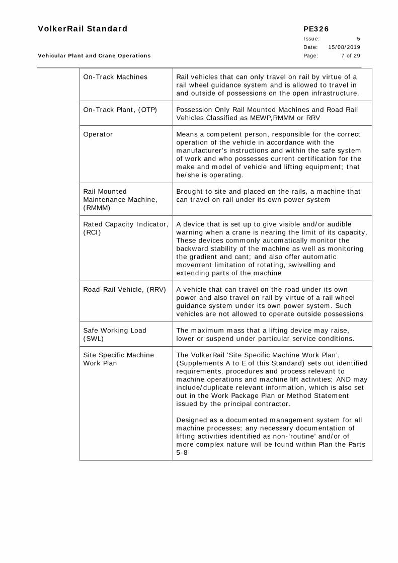
On-Track Machines Rail vehicles that can only travel on rail by virtue of a rail wheel guidance system and is allowed to travel in and outside of possessions on the open infrastructure.
On-Track Plant, (OTP) Possession Only Rail Mounted Machines and Road Rail Vehicles Classified as MEWP,RMMM or RRV
Operator Means a competent person, responsible for the correct operation of the vehicle in accordance with the manufacturer’s instructions and within the safe system of work and who possesses current certification for the make and model of vehicle and lifting equipment; that he/she is operating.
Rail Mounted Maintenance Machine, (RMMM)
Brought to site and placed on the rails, a machine that can travel on rail under its own power system
Rated Capacity Indicator, (RCI)
A device that is set up to give visible and/or audible warning when a crane is nearing the limit of its capacity. These devices commonly automatically monitor the backward stability of the machine as well as monitoring the gradient and cant; and also offer automatic movement limitation of rotating, swivelling and extending parts of the machine
Road-Rail Vehicle, (RRV) A vehicle that can travel on the road under its own power and also travel on rail by virtue of a rail wheel guidance system under its own power system. Such vehicles are not allowed to operate outside possessions
Safe Working Load (SWL)
The maximum mass that a lifting device may raise, lower or suspend under particular service conditions.
Site Specific Machine Work Plan
The VolkerRail ‘Site Specific Machine Work Plan’, (Supplements A to E of this Standard) sets out identified requirements, procedures and process relevant to machine operations and machine lift activities; AND may include/duplicate relevant information, which is also set out in the Work Package Plan or Method Statement issued by the principal contractor.
Designed as a documented management system for all machine processes; any necessary documentation of lifting activities identified as non-‘routine’ and/or of more complex nature will be found within Plan the Parts 5-8
VolkerRail Standard PE326 Issue: 5 Date: 15/08/2019 Vehicular Plant and Crane Operations Page: 8 of 29
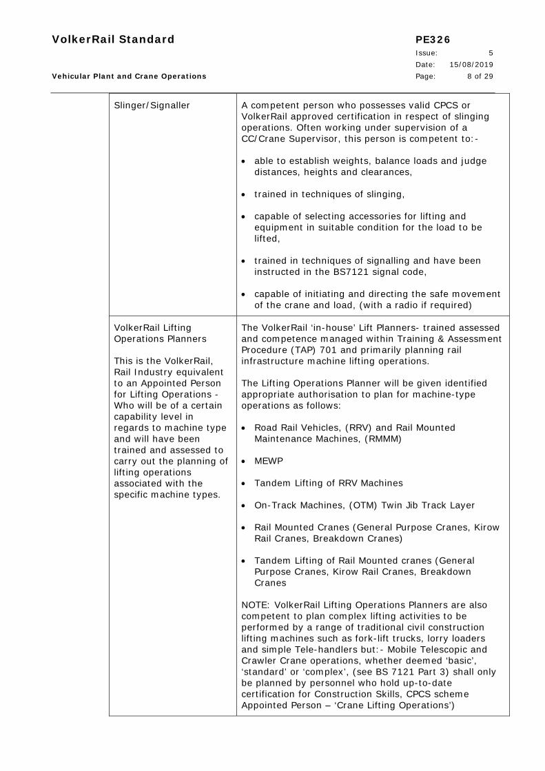
Slinger/Signaller
A competent person who possesses valid CPCS or VolkerRail approved certification in respect of slinging operations. Often working under supervision of a CC/Crane Supervisor, this person is competent to:-
able to establish weights, balance loads and judge distances, heights and clearances,
trained in techniques of slinging,
capable of selecting accessories for lifting and equipment in suitable condition for the load to be lifted,
trained in techniques of signalling and have been instructed in the BS7121 signal code,
capable of initiating and directing the safe movement of the crane and load, (with a radio if required)
VolkerRail Lifting Operations Planners
This is the VolkerRail, Rail Industry equivalent to an Appointed Person for Lifting Operations - Who will be of a certain capability level in regards to machine type and will have been trained and assessed to carry out the planning of lifting operations associated with the specific machine types.
The VolkerRail ‘in-house’ Lift Planners- trained assessed and competence managed within Training & Assessment Procedure (TAP) 701 and primarily planning rail infrastructure machine lifting operations.
The Lifting Operations Planner will be given identified appropriate authorisation to plan for machine-type operations as follows:
Road Rail Vehicles, (RRV) and Rail Mounted Maintenance Machines, (RMMM)
MEWP
Tandem Lifting of RRV Machines
On-Track Machines, (OTM) Twin Jib Track Layer
Rail Mounted Cranes (General Purpose Cranes, Kirow Rail Cranes, Breakdown Cranes)
Tandem Lifting of Rail Mounted cranes (General Purpose Cranes, Kirow Rail Cranes, Breakdown Cranes
NOTE: VolkerRail Lifting Operations Planners are also competent to plan complex lifting activities to be performed by a range of traditional civil construction lifting machines such as fork-lift trucks, lorry loaders and simple Tele-handlers but:- Mobile Telescopic and Crawler Crane operations, whether deemed ‘basic’, ‘standard’ or ‘complex’, (see BS 7121 Part 3) shall only be planned by personnel who hold up-to-date certification for Construction Skills, CPCS scheme Appointed Person – ‘Crane Lifting Operations’)

VolkerRail Standard PE326 Issue: 5 Date: 15/08/2019 Vehicular Plant and Crane Operations Page: 9 of 29
Note: RIS-1700-PLT is not mandated for the use on Network Rail managed infrastructure and has not been shown in the table below as a crane controller cannot amend lift plans.
Activity
Competence when working on NWR
Managed Infrastructure
Equivalent competence or terminology used in the
standards below:-
LOLER Construction Industry standard BS7121
Produces and Authorises Lift Plans
Lifting Operations Planner
Competent Person
Appointed Person
Amends and Authorises Lift plans on site
Lifting Operations Planner
Competent Person
Appointed Person
Safe control of lifting operations
Crane Controller Appropriately Supervised
Crane Supervisor
Attaches or removes an accessory for lifting
Crane Controller or Slinger
Load Handler Slinger/Signaller
Relays Crane Controller Commands
Slinger No equivalent term specified
Slinger/Signaller
Provides guidance for the movement of vehicles off track when manoeuvring
Banksman
(Does not include lifting operations)
No equivalent term specified
Banksman
(Does not include lifting operations)

VolkerRail Standard PE326 Issue: 5 Date: 15/08/2019 Vehicular Plant and Crane Operations Page: 10 of 29
5. References
5.1 British Standards
BS 6166-1 Lifting Slings – Part 1: Methods of Rating
BS 6166-3 Lifting Slings – Part 3: Guide to the selection and safe use of lifting slings for multi-purpose
BS 7121, Part 1, 2006 Code of Practice for the safe use of cranes, General
BS 7121, Part 3, 2006 Code of Practice for safe use of cranes, Mobile Cranes
BS 7121, Part 4, 2006 Code of Practice for the safe use of cranes, Lorry Loaders
BS 7121, Part 5, 2006 Code of Practice for the safe use of cranes, Tower Cranes
5.2 Legislation
LOLER 1998 Lifting Operations & Lifting Equipment Regulations, (Plus Code of Practice, Plus HSE Guidance)
PUWER 1998 The Provision and Use of Work Equipment Regulations 1998, (Plus Code of Practice, Plus HSE Guidance)
5.3 Construction and Industry Standards
CIRIA - ‘C703’ Construction Industry Research and Information Association- Crane Stability on Site
Network Rail Standard NR/L2/RMVP/0200
Plant Operations Manual (All modules)
Railway Group GE/RT8000 Rule Book
Modules OTM and Handbook 15
Railway Group GE/RT8024 Persons working On or Near to AC Electrified Lines
RSSB RIS-1530-PLT Rail Industry Standard for Engineering Acceptance of On-Track Plant & Associated Equipment
RSSB RIS-1700-PLT Safe Use of Plant for Infrastructure Work
VolkerRail Standard PE326 Issue: 5 Date: 15/08/2019 Vehicular Plant and Crane Operations Page: 11 of 29 5.4 VolkerRail Standards
P&E/315 Plant Working Adjacent to Operational Lines
P&E/321 Operational & Engineering Arrangements for the use of the KIROW Cranes within Possessions
SAF/33 Management Arrangement for Hiring In/Out of OTM/OTP Machines – SMS Compliance
5.5 HSE Guidance
Brief Guide to The Work at Height Regulations 2005
HSG 144, The Safe Use of Vehicles on Construction Sites
INDG199 (rev1)
INDG313 Safe Unloading of Steel Stock
Simple Guide to LOLER 1998
Simple Guide to PUWER 1998
Site inspection - workplace transport checklist
The selection and management of mobile elevating work platforms
Workplace Transport Safety – An Overview
6. Management Arrangements
Responsibilities
The Vehicular Plant Planning ‘team’ consists of:-
Project Manager – The person whose holds responsibility for all the project matters inclusive of Plant requirements and logistics.
Appointed Person/Lifting Operations Planner - A person who holds an appointed person qualification such as "CPCS Appointed Person" for example and qualified to carry out and authorise Mobile Road Crane lifting operations
VolkerRail Appointed Person/Lifting Operations Planner RMC - A person who holds an appointed person qualification such as "CPCS Appointed Person" for example and has also been trained to carry out, plan and authorise Rail Mounted Crane lifting operations.
VolkerRail Appointed Person/Lifting Operations Planner, RRV, MEWP, TRM, Telehandler, Hi-Ab - A person who holds an appointed person qualification in regards to the specific equipment types and has been trained through VolkerRail's own training and assessment regime.
Crane Supervisor / Crane Controller (for OTP and OTM) a person who holds the industry competence for controlling the movement of Mobile cranes/Rail Mounted Cranes/RRV/MEWPS/RMMM
VolkerRail Standard PE326 Issue: 5 Date: 15/08/2019 Vehicular Plant and Crane Operations Page: 12 of 29
Drivers / Operators - A person who holds the industry competence for operating a specific type of Plant and Machinery
Slingers-Signallers - Often the Crane Controller/s for OTP and OTM but must be a person who has been trained in the industry competency for slinger signalling operation.
Banksman - Must be a Machine Controller for OTP in Rail Mode but must also have been trained or assessed in regards to Banksman duties in regards to industry competency requirements.
Project Manager
The Project Manager shall:
a) Be responsible for ensuring that this standard is followed and identifying the Plant Operating Licence and Safety Certification requirements for the relevant plant and equipment working on the project.
b) Establish the roles and responsibilities within the project team for delivery of this standard.
c) Ensure that Machine Work Plans are considered at the start of the Project
d) Ensure that Lifting Plans are considered at the start of the Project and where lifting operations are necessary, appoint a VolkerRail Lifting Operations Planner as the site Appointed Person in accordance with BS7121-1 section 4.2.2.
e) Make arrangements for the provision of mentoring by a 2nd fully competent VolkerRail Lifting Operations Planner in the event that the appointed VolkerRail Lifting Operations Planner is under mentoring
f) Determine with the Site Appointed Person, the complexity of lifting operations and whether the nature of the activities can be defined as being ‘routine’ in terms of the lift operation and other site activities and the environment.
g) Ensure that any sub-contracted CPCS ‘Appointed Person, Lifting Operations’ responsible for the organisation & control of ‘Contract Lifts’ - supply copies of their planning documentation to the site Appointed Person in advance of lifts taking place
h) Agree the terms & conditions of sub-contracted vehicular plant and lifting activities under the Construction Plant Association, (CPA) standard terms & conditions and supplementary conditions.
i) Monitor and review appointments regularly, particularly in the event of changing site conditions, complexity or workload
NOTE: When appointing a VolkerRail Lifting Operations Planner as a site Appointed Person, the variety and complexity of the lifting operations to be undertaken should be considered, as well as all the problems that may arise from proximity hazards and the environment. The appointee must also be given the time and resources to carry out the duties involved. This will include consulting others with specialist
VolkerRail Standard PE326 Issue: 5 Date: 15/08/2019 Vehicular Plant and Crane Operations Page: 13 of 29
knowledge and experience, and delegating duties and tasks for any part of the safe system of work to suitably qualified individuals or sub-contractors.
The Project Manager must monitor and review the appointment through the training and assessment process to ensure that the Appointee is still fulfilling the requirements of this standard and that every lifting operation has a safe system of work. Changes in the workload or in the type and complexity of lifting operations may make it necessary to select a different site Appointed Person or provide the existing appointee with additional training and familiarisation. VolkerRail Training and Assessment Procedure TAP/701 details and validates individual VolkerRail Lifting Operations Planner competency, within an ‘in-house’ regime for specific machine type operations. Where a more complex lifting operation is required then the Project Manager should seek advice from the Engineering Director as to the level of competence required for the site Appointed Person.
All Lifting Operations Planners and Appointed Persons must display the following attributes:-
1. The required planning skills
2. The ability to understand the most current standards and legislative documentation associated with lifting practices
3. The ability to solve simple technical problems
4. The ability to provide clear and concise written and verbal communication
5. The ability to assimilate and adhere to rules and regulations
6. The ability to conduct effective risk assessments
7. The ability to undertake basic mathematical calculations
VolkerRail Appointed Person
The VolkerRail Appointed Person has responsibility for the safe organisation and control of his/her planned lifting operations and provides a safe system of working by properly planning the lifting operation, including preparation of a comprehensive Site Specific Machine Work Plan, including Lifting Plans. They shall:
a) Consult all parties involved in the selection and hire of the crane/s
b) Prepare the Site Specific Machine Work Plan, including Lifting Plan and carry out site risk assessment himself, but can routinely delegate control measures to a competent person such as a Crane Supervisor / Crane Controller or other competent person who can take responsibility for the lifting operation on site.
c) Review and update the Site Specific Machine Work Plan and Lifting Operations Plan/s (Forms P&E/326/F/01, 05, 06 and 07 to this standard and forming part of the Project Health and Safety Plan)
d) Liaise with sub-contractor’s crane teams, correlating Rail Crane Lift Plan (KIROW and/or other Contracted Rail Crane Lift Plans) and Mobile Telescopic and Crawler - Crane Lift Plans (CPCS Contract Lift Plans) into the framework of the Site Specific Machine Work Planning System
VolkerRail Standard PE326 Issue: 5 Date: 15/08/2019 Vehicular Plant and Crane Operations Page: 14 of 29
e) Ensure that Lifting Plans for general lifts are drawn up, as well as specific statements for complex operations
f) Ensure adequate foundations are provided for all cranes and all permits are in place
g) Liaise with local airfields, if required
h) Liaise with local authorities, police, etc., if road closures required or abnormal loads travelling to site
i) Liaise with local authorities, highways authorities, etc. if cranes will over sail or be erected close to public highways
j) Liaise with the owners of neighbouring properties for over sailing rights, if required
k) Maintain their own competency by maintaining a VolkerRail and/or CPCS Lift Planning Portfolio, keeping abreast with industry best practice and new regulations or standards
See next page for flow-chart process for the Site Specific Machine Work Planning System
VolkerRail Standard PE326 Issue: 5 Date: 15/08/2019 Vehicular Plant and Crane Operations Page: 15 of 29
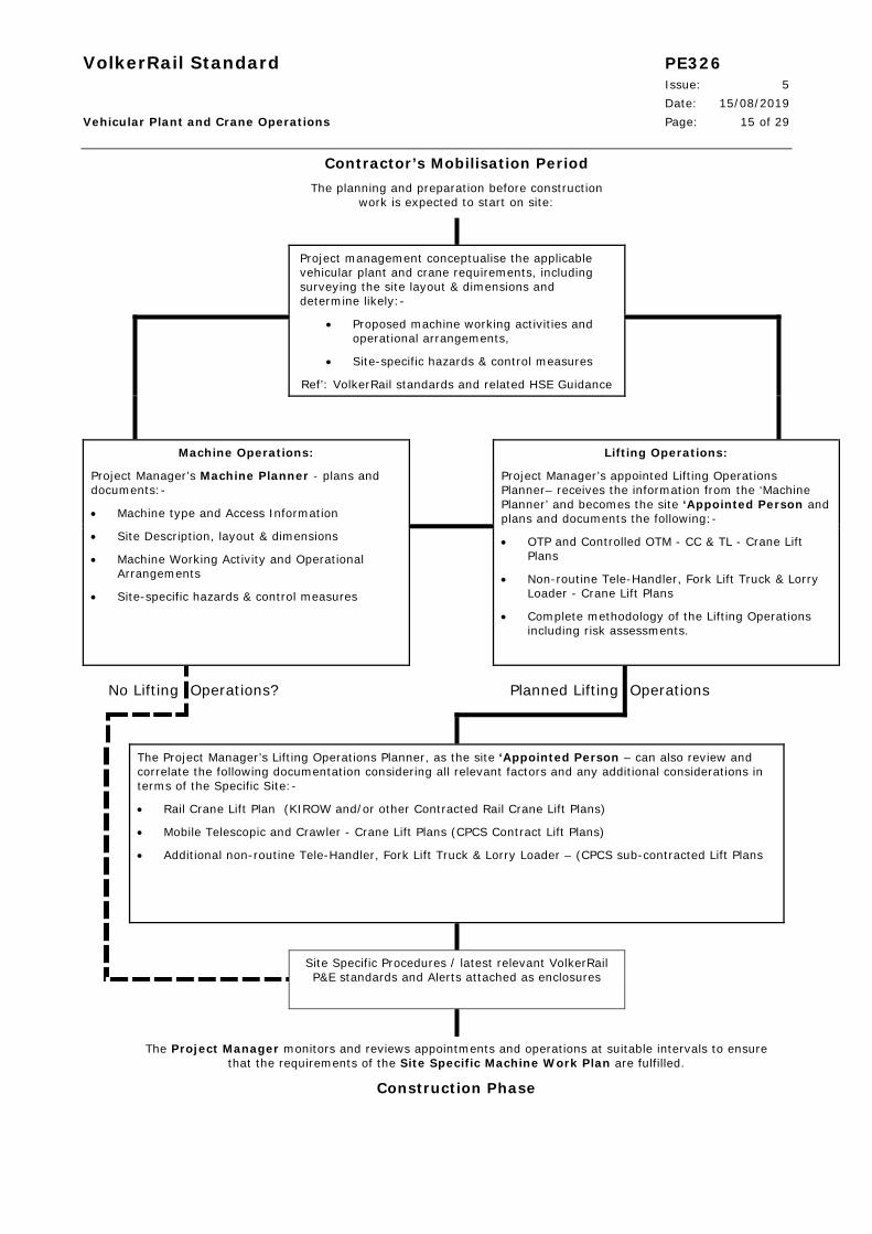
Contractor’s Mobilisation Period The planning and preparation before construction
work is expected to start on site:
Project management conceptualise the applicable vehicular plant and crane requirements, including surveying the site layout & dimensions and determine likely:-
Proposed machine working activities and operational arrangements,
Site-specific hazards & control measures
Ref’: VolkerRail standards and related HSE Guidance
Machine Operations:
Project Manager’s Machine Planner - plans and documents:-
Machine type and Access Information
Site Description, layout & dimensions
Machine Working Activity and Operational Arrangements
Site-specific hazards & control measures
Lifting Operations:
Project Manager’s appointed Lifting Operations Planner– receives the information from the ‘Machine Planner’ and becomes the site ‘Appointed Person and plans and documents the following:-
OTP and Controlled OTM - CC & TL - Crane Lift Plans
Non-routine Tele-Handler, Fork Lift Truck & Lorry Loader - Crane Lift Plans
Complete methodology of the Lifting Operations including risk assessments.
No Lifting Operations? Planned Lifting Operations
The Project Manager’s Lifting Operations Planner, as the site ‘Appointed Person – can also review and correlate the following documentation considering all relevant factors and any additional considerations in terms of the Specific Site:-
Rail Crane Lift Plan (KIROW and/or other Contracted Rail Crane Lift Plans)
Mobile Telescopic and Crawler - Crane Lift Plans (CPCS Contract Lift Plans)
Additional non-routine Tele-Handler, Fork Lift Truck & Lorry Loader – (CPCS sub-contracted Lift Plans
Site Specific Procedures / latest relevant VolkerRail P&E standards and Alerts attached as enclosures
The Project Manager monitors and reviews appointments and operations at suitable intervals to ensure that the requirements of the Site Specific Machine Work Plan are fulfilled.
Construction Phase
VolkerRail Standard PE326 Issue: 5 Date: 15/08/2019 Vehicular Plant and Crane Operations Page: 16 of 29
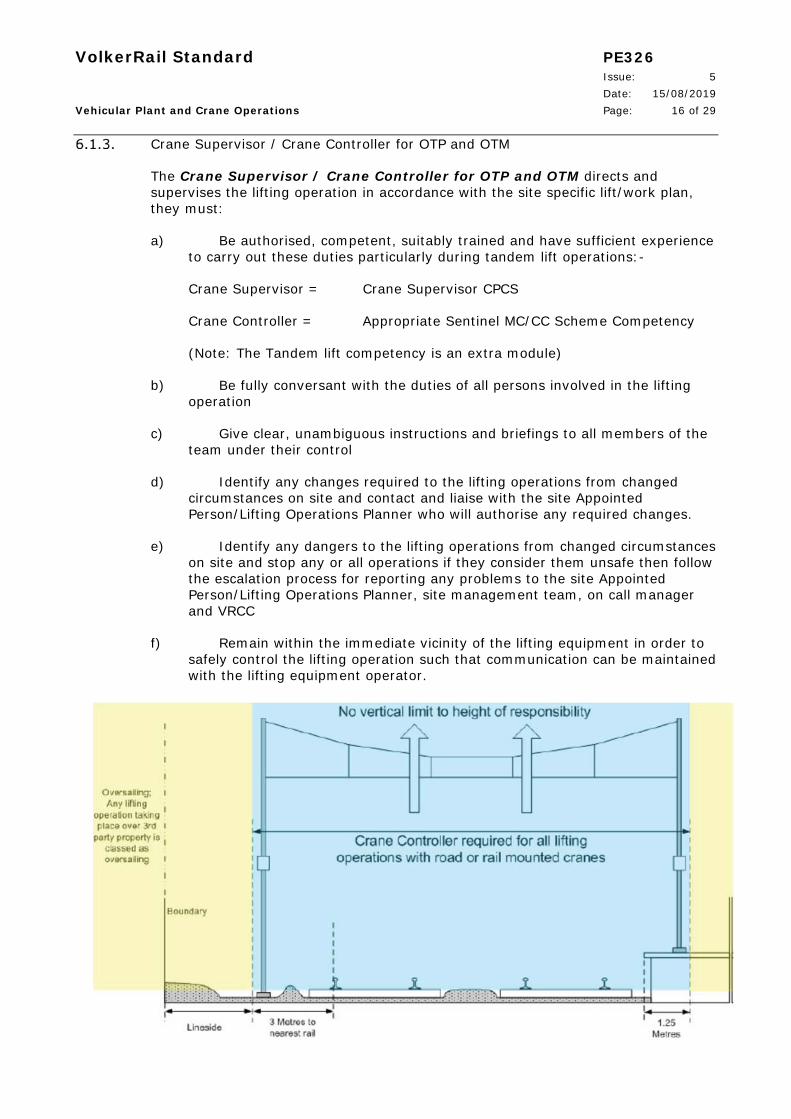
Crane Supervisor / Crane Controller for OTP and OTM
The Crane Supervisor / Crane Controller for OTP and OTM directs and supervises the lifting operation in accordance with the site specific lift/work plan, they must:
a) Be authorised, competent, suitably trained and have sufficient experience to carry out these duties particularly during tandem lift operations:-
Crane Supervisor = Crane Supervisor CPCS
Crane Controller = Appropriate Sentinel MC/CC Scheme Competency
(Note: The Tandem lift competency is an extra module)
b) Be fully conversant with the duties of all persons involved in the lifting operation
c) Give clear, unambiguous instructions and briefings to all members of the team under their control
d) Identify any changes required to the lifting operations from changed circumstances on site and contact and liaise with the site Appointed Person/Lifting Operations Planner who will authorise any required changes.
e) Identify any dangers to the lifting operations from changed circumstances on site and stop any or all operations if they consider them unsafe then follow the escalation process for reporting any problems to the site Appointed Person/Lifting Operations Planner, site management team, on call manager and VRCC
f) Remain within the immediate vicinity of the lifting equipment in order to safely control the lifting operation such that communication can be maintained with the lifting equipment operator.

VolkerRail Standard PE326 Issue: 5 Date: 15/08/2019 Vehicular Plant and Crane Operations Page: 17 of 29
Crane Controller required for all lifting operations with road or rail mounted cranes
Where the lifting machine or load could foul the line a crane controller is required.
Where the lifting machine or load cannot foul the line then a crane controller or crane supervisor to BS7121 must be provided.
The lateral dimensions shown are applicable at any height above rail level
Note: Exclusions to the above in regards to a crane controller not being required can be met by following all of the criteria below:-
A previously agreed risk assessment has demonstrated that it is not possible to foul any railway line during loading/unloading of road vehicles.
The lifting equipment involved is a knuckle boom crane and the overturning moment is limited by means of a hydraulic relief valve or similar safety device.
A full risk assessment has been undertaken to show that loading/unloading and placement of the load does not increase risk to the lifting equipment or infrastructure.
The risk assessment and method statement are with the crane.
Drivers / Operators
Drivers / Operators of all vehicular plant, machines and cranes in VolkerRail Project sites must:
a) Be competent, and hold a current Construction Skills – Construction Plant Competence Scheme, (CPCS) Card for operating the appropriate category of vehicle, machine or crane. NOTE: Sentinel OTP Operator Scheme Card for OTP Host Machines and Rail Plant Association Industry equivalent certification for OTM Cranes
b) Fit to applicable standard with eyesight, hearing and reflexes being most important
c) Physically able to operate the plant or crane safely
d) Able to judge distances, heights and clearances
e) Conversant with the duties of a Banksman; and Slinger-Signallers where appropriate and understand the signals given to the standards of BS 7121
f) Authorised to operate the vehicle, machine and/or crane
In particular, whilst fulfilling their safety critical competency Crane Operators shall:
g) Check the crane before the start of each shift

VolkerRail Standard PE326 Issue: 5 Date: 15/08/2019 Vehicular Plant and Crane Operations Page: 18 of 29
h) Inspect the crane weekly and record the results of the inspection in the appropriate register
i) Carry out routine maintenance as instructed
j) Leave the crane in a safe condition when unattended, i.e. power or engine switched off and keys removed
k) Leave the crane when out of service (e.g. overnight or in high winds) in a safe and secure condition in accordance with the manufacturers’ instructions
l) Operate the crane in a safe manner in accordance with the Slinger-Signaller’s directions, and the Lifting Operations Plan for the current operation
m) Not operate the crane unless they are confident that the load can be handled safely in the prevailing wind conditions
n) Report incidents and defects to the crane Owner, VRCC, site and on call line management.
Slingers – Signaller
The duties of Slinger, Signaller and Banksman are often combined in to one person’s responsibility and it is usual for this person to be competent and certified in all three functions. However, on larger or more complex lifts these duties may be performed by separate individuals and the duties are described separately as:
Slinger: The Slinger is responsible for attaching and detaching the load and for using the correct lifting equipment in accordance with the Lifting Plan. The Slinger directs the Crane Operator to take the weight of the lift load and ensures the load is safely slung before it is lifted to any height. The Slinger is also responsible for checking there are no overhead obstacles and for the attachment of a tag line for controlling the load once suspended, if required by the Lifting Plan or site conditions.
Signaller: Once the load is suspended the Signaller relays directions to the Crane Operator for the movement of the load to its destination using either specified hand signals or via radio communications. If more than one Signaller is being used only one Signaller must give instructions at any one time and a safe system of transfer should be in place as responsibility moves between Signallers.
Every Crane used on VolkerRail Sites must have at least one Slinger-Signaller allocated to it whilst being set-up or working and when not OTP Crane Controllers they are to hold appropriate Slinger-Signaller ‘Construction Skills CPCS Cards’.
The Slinger-Signaller must be:-
a) Fit, particularly in respect of eyesight, hearing, reflexes and agility
b) Physically able to handle the lifting accessories
c) Able to establish weights, balance loads and judge heights, distances and clearances
VolkerRail Standard PE326 Issue: 5 Date: 15/08/2019 Vehicular Plant and Crane Operations Page: 19 of 29
d) Capable of directing the safe movement of the crane and load, with clear, precise instructions
e) Aware of their responsibilities and their limits
f) Authorised to carry out their duties
Banksman
The Banksman must hold a current Construction Skills – Construction Plant Competence Scheme (CPCS) Card to:
a) Guide vehicles and cranes safely on and off site, especially when the vehicle / crane is reversing or performing tight maneuvers.
b) Direct the Driver / Crane Operator to the correct location shown in the Site Specific Machine Work Plan and for ensuring there is hazard free access and egress and movement around site if lifts take place in different locations on site.
c) Be fully competent in the Health and Safety (Signs and Signals) Regulations 1996 L64
NOTE: This person must be a Machine Controller for OTP in Rail Mode
Delivery of vehicular plant and crane operational personnel
In delivery of vehicular plant and crane operational personnel, the Project Manager and/or Appointed Person can refer to Section 6.1
The present Sentinel OTP Controller and Sentinel OTP Operator Schemes do not differentiate between host machine/miscellaneous equipment manufacturers and some equipments/attachments are not specifically mentioned within the scheme module matrix. Such competency requirements remain within the arrangements of the Project Manager and such equipments as example may be:
Non rail-borne plant operating on or near the line
Drilling and piling equipments and attachments
Multi-point and multi-functional hydraulic beams and grabs
Agreement with regard to attributing plant related competencies in these instances is to be sought from the OTP Compliance Manager or the VolkerRail Plant Technical Manager
VolkerRail Standard PE326 Issue: 5 Date: 15/08/2019 Vehicular Plant and Crane Operations Page: 20 of 29
Plans and Planners
a) Site Specific Machine Work Plans
The VolkerRail Site Specific Machine Work Planning system documents the safe, planned execution of all vehicular plant ‘machine’ and ‘lifting’ activities associated with multiple site specific planned methodologies and safe systems of work. The Plan addresses the need for a holistic and cohesive system by which all the planned operations can be documented and referenced to within method statements and Work Package Plans (WPP). The application of the Work Plan, extrapolates the range of accepted common activities on or near the line so that sections within the template can easily relate to and encompass all machine operations within the boundary fence and also out into non-rail civil construction worksites.
General site specific elements are documented in a useful combined 2-page Task-Briefing format template, whereas lift planning is documented in standalone, associated documents that are created and verified only by VolkerRail Lifting Operations Planners.
b) Planners
The Project Manager shall identify a suitable competent Machine Planner to document general site specific vehicular plant operations in a useful combined 2-page Task-Briefing format template, Form P&E/326/F01 Site Specific Machine Work Plan, Parts 1-4.
The Machine Planner must visit and assess the entire site, considering all relevant factors and any additional considerations of a site specific nature prior to preparing the plan. (Note: The Machine Planner can also be the Site Appointed Person providing he has the lift planning competence)
Where the scope of works includes machine lifting operations, the Project Manager shall appoint a VolkerRail Lifting Operations Planner to site Appointed Person, to generate VolkerRail Lifting Operations Plans and/or correlate contracted Lift Plans using Site Specific Work Plan Parts 5 to 7 Forms P&E/326/F05 – F07 Site Specific Machine Work Plan Parts 5-7. This competent person takes over the information from the ‘Machine Planner’ and visits the site to assess the requirements in terms of the loads to be moved, dimensions, positions for off loading / stacking etc. In order to ensure effective development and implementation, the Site Appointed Person acts on behalf of the site management and has overall control of lifting operations on the site. As a rule, there will be only one VolkerRail Site Appointed Person appointed on each project. The exception to this is on the very largest of projects that are sub divided into substantially autonomous sections.
c) Subcontractor contract lifting
Each sub contractor carrying out contract lifting operations will be required to provide their own Appointed Person and where VolkerRail is the Principle Contractor; these Appointed Persons and their lifting plans are subordinate to the VolkerRail Site Appointed Person, who must be satisfied with Lifting Operations and Lifting Equipment Regulations compliance.
VolkerRail Standard PE326 Issue: 5 Date: 15/08/2019 Vehicular Plant and Crane Operations Page: 21 of 29
As set out in 6.1.3, the VolkerRail Lifting Operations Planner, as the Project Manager’s Site Appointed Person will liaise with sub-contractor’s crane teams, correlating Rail Crane Lift Plans, (KIROW and/or other Contracted Rail Crane Lift Plans) and Mobile Telescopic and Crawler - Crane Lift Plans (CPCS Contract Lift Plans) into the framework of the Site Specific Machine Work Planning System. NOTE: All sub contractor Appointed Persons must have a CPCS Card and adequate experience to carry out their duties competently
Delivery and Collection
a) In vehicular plant and crane delivery the Project Manager shall ensure that all parties exchange information about the main risks involved and agree who will do what to control risks.
b) Project Managers must assess delivery and collection risks and reduce them as far as reasonably practicable, (ALARP) in consultation with safety representatives, drivers and personnel involved and consider what further steps may be taken in co-operating to reduce risk. This shall include:
Assessment of safety arrangements for deliveries and collections, assessed before orders are taken or placed which should prevent deliveries being delayed or sent back because a site can't handle the load or the vehicle carrying it.
Incorporation of safety arrangement in ‘order-placing’ and ‘order-takings’.
Provision of adequate information for each delivery or collection driver beforehand- such as being issued with a copy of the Specific Machine Work Plan, Parts 1-4
c) Where there are regular deliveries from a particular Owner or Carrier, (the ‘haulier’ or other company carrying the goods) then a written delivery plan shall be agreed by all parties. If something about a particular delivery may make it unsafe to rely on the usual plan, the delivery should not start until new control measures have been agreed. When the Project Manager, Owners and Carriers deal with each other on a "last-minute, one-off" basis then the Project Manager should ensure that all the information at the time of the order is considered in line with the required risk mitigation. It should therefore be practicable to exchange basic delivery safety information, and agree on the main precautions at the time the order is placed.
d) In some situations, 3rd parties may be involved; for instance, where an order is placed with an Owner who arranges for a 3rd party company to provide the goods, who in turn arranges for a Carrier to make the delivery. Such complex arrangements can easily go wrong due to misunderstandings and failures in communication. The Project Manager shall consider the dangers and risks involved associated with this type of delivery before entering into these arrangements.
e) The three general principles which shall be agreed by the Project Manager, Owners and Carriers are:-
sending out of the Specific Machine Work Plan, Parts 1-4 Form P&E/326/F01 and other relevant related safety information on deliveries and collections to other parties in the delivery chain

VolkerRail Standard PE326 Issue: 5 Date: 15/08/2019 Vehicular Plant and Crane Operations Page: 22 of 29
the shared provision of safety information on deliveries and collections from the Project manager, Owners and Carriers in the delivery chain
agreement of a safe delivery plan
Documented Planning
Movements of all vehicular plant & cranes on Network Rail or civil construction sites are only to be carried out as long as they are supported by documented processes, including suitable risk assessments and authorised safe systems of work. In addition, it is to be noted that on Network Rail Infrastructure:-
It is NOT necessary for a Machine Controller to be appointed for each item of On-Track Plant (OTP)
With the exception of Mobile Elevated Working Platforms, (MEWP) in working mode, all Machine Controlled OTP can be Controlled by the Operator, should the Operator hold the applicable Machine Controller competencies
NOTE: Such methods of work must be shown safe by risk assessment and the detail shown within method statements and especially, the Site Specific Machine Work Plan. Planning the use of OTP, controlled by ‘Operator/Controllers’ must first be approved by either the OTP Compliance Manager, VolkerRail Plant’s Technical Manager or the Engineering Director
Copies of Form P&E/326/F01 Site Specific Machine Work Plan Part 1-4 are to be briefed to and held in a work-site by all Banksman, Machine Controllers, Crane Supervisors and Crane Controllers.
Site Specific Machine Work Plan Parts 1-4 (Form P&E/326/F01)
Form P&E/326/F01 has been developed to characterise the main site specific elements of documented planning requirements as follows:-
Part 1: Machine and Access Information
Part 2: Site Description, layout & dimensions
Part 3: Machine Working Activity and Operational Arrangements
Part 4: Site-specific hazards & control measures
The outline tasks involving lifting activities are prescribed within Part 3 ‘Machine Working Activity’ by the Project Manager’s Site Appointed Person, (VolkerRail Lifting Operations Planner). Other non-lifting vehicular plant operations are prescribed as Banksman / Machine Controller activities and are immediately organised & controlled by Banksman or Machine Controllers as appropriate.
VolkerRail Standard PE326 Issue: 5 Date: 15/08/2019 Vehicular Plant and Crane Operations Page: 23 of 29
Site Specific Machine Work Plan Parts 5-7 (Forms P&E/326/F05, 06 and 07)
Both Civil Construction and Rail Industry crane operations industry standards and best practice are based on the regulations within the LOLER and the best practice within the British Standard 7121 Series, ‘Code of Practice for the Safe Use of Cranes’.
a) The Project Manager’s Site Appointed Person, (VolkerRail Lifting Operations Planner) shall ensure that all lifting operations are planned to ensure that they are carried out safely and that all foreseeable risks have been taken into account and based on a Site Visit using the Site Specific Machine Work templates Forms P&E/326/F05, 06 or 07 to define lift planning for different machine types as follows:-
Part 5: OTP and Controlled OTM - CC & TL - Crane Lift Plans
Part 6: Tele-Handler, Fork Lift Truck & Lorry Loader - Crane Lift Plans
Part 7: MEWP – Machine Work Lift Plans
b) VolkerRail Lift Operations Planners complete Part 5, Part 6 and Part 7 Lift Plans which are the most frequently produced lift plans within VolkerRail, a requirement due to inherent physical limitations of many of the machines.
c) For complex Kirow rail crane and sub-contracted Mobile Road Crane Contract Lifts, the planning documents need to be developed in liaison with the Site Appointed Person and Project Manager, this in turn will give all the relevant information in relation to the required works needed in a WPP format thus taking into consideration all the relevant associated risks and hazard within the worksite.
d) Where sub-contracted, CPCS Appointed Person- Lifting Operations lifting plans are supplied; the VolkerRail Site Appointed Person shall review and comment on the lift planning documentation, ensuring LOLER compliance and compatibility with all site specific vehicular activities.
e) In the case of lifting activities, low risk, repetitive and ‘routine’ operations, such as many of those commonly associated with MEWP, Tele-Handlers, Fork Lift Trucks & Lorry Loaders, the often sub-contracted ‘routine’ lifts should have been planned in the first instance for the particular machine and equipment type and it is to be expected that ‘generic’ plans will be held on the vehicle for Operator use. This shall be verified by the Project Manager’s Site Appointed Person. The carrying out of ‘routine’ lifts, immediately organised and controlled by the Operator, has not removed any legal responsibility from the Project Management. In these instances, the Operator has merely been given authority to act as the Project Manager’s Appointed Person for that activity and is satisfying the Employing Organisation's overall planning requirement. The Part 6 template is created for use by a VolkerRail Lifting Operations Planner as a mechanism for planning such lifting operations- when the task and/or load OR the characteristics of the machine and/or lifting equipment is assessed as being NOT being low risk, repetitive and/or routine.

VolkerRail Standard PE326 Issue: 5 Date: 15/08/2019 Vehicular Plant and Crane Operations Page: 24 of 29
‘Generic’ Lift Plans
Forms P&E/326/F05, 06 and 07 are plans for a common range of activities that take place so frequently and to such an extent, that by nature, they almost demand to be defined as being ‘routine’.
As already indicated in section 6.3.1, due to the potential variance, amount of machines or vehicles available to the Project Manager and the differences in capacities between machines, it is still not practicable in terms of the VolkerRail scope of operations to define such activity as ‘routine’.
However it is perfectly acceptable for a VolkerRail Lift Operations Planner to generate a suite of generic lifting plans based on an established range of defined machines and accessories, known and calculated loads and physical parameters such as level ground and canted track.
The Management of VolkerRail Lifting Plans
a) The crane lifting plans within the Site Specific Machine Work Plan must constitute a complete detailed plan, such that any experienced Crane Controller or Crane Supervisor as appropriate could take the plan/s, visit site and assess the site and know exactly what to do i.e. where the cranes and loads should be positioned etc. Nothing must be taken for granted and the Crane Controller / Crane Supervisor must not be left to plan the detail of the lifts.
b) These plans document the process by which the safe, control & organisation of planned lifting activities will take place in association with site specific planned methodology and safe systems of work. They will be verified by the Crane Controller or Crane Supervisor in pursuance of their duty whilst carrying out the documented activities and questions and in certain circumstances, clarification might be sought from Lift Operations Planners as appropriate.
c) The lifting plan/s requires details of pick up and set down locations in all but the simplest situations. The lifting plan/s must always contain copies of all the detail duty charts that are necessary to deliver the plan for the specific machines to be used. It must also contain any VolkerRail specific briefs regarding lifting machines, ancillary equipment or trailers. The completed lifting plan/s will be concluded and signed off by a VolkerRail Lift Operations Planner, (except see 6.3.2 d) review and comment on sub-contracted Mobile Road Crane ‘Contract Lift’ planning documentation) indicating that he/she accepts responsibility for the compliance and thoroughness of the plan that has been produced.
d) Where a Lift Operations Planner is under mentoring (see Training & Assessment Procedure TAP/701) then a 2nd fully competent certified Lift Operations Planner acting as the ‘Checker’ should determine that the planned lifts / moves are in accordance with the rules (applicable to lifting activities) and capabilities of the machine and ancillary equipment.
e) The Project Manager shall ensure that VolkerRail Lifting Operations Planner lifting plan/s are ‘accepted and signed off’ not later than 3 working days prior to the machine and crane working taking place and unauthorised plans printed directly without signature are not valid.
VolkerRail Standard PE326 Issue: 5 Date: 15/08/2019 Vehicular Plant and Crane Operations Page: 25 of 29 f) The lifting plan/s will be produced for work scheduled on a particular day or
days. The plan does not automatically become invalid in the event that the work is re-scheduled as long as the Lift Operations Planner authorises this, provided he/she is satisfied the content remains valid.
‘Late’ Lift Plans
Both ‘Machine’ and ‘Lift’ planning elements of the Site Specific Machine Work Plan can be documented and/or collated by the same appointed person, but it is only allowed, in exceptional circumstances where lift planning has been previously planned and the same information to the work and site specifics remains constant based on information and evidence submitted by a Project Manager’s Machine Operations Planner who has visited the site.
NOTE: Notifications of such intended Lift Planning- ‘selection’ of generic Form P&E/326/F05, 06 and 07 lifting Plans shall be passed to the OTP Compliance Manager, VolkerRail Plant Technical Manager or Engineering Director, for approval prior to the proposed lifts taking place.
The Immediate Organisation and Control of Lifts
The immediate operational Organisation and Control of lifting activities is the responsibility of the Crane Controller or Crane Supervisor in application of the appropriate lifting plans. The Crane Supervisor will contact the Appointed Person/Lifting Operations Planner in accordance with 6.1.3 when alterations are required or parameters have changed.
Low Risk and Routine work (well within the capability of a single machine) may be carried out under the immediate direction of a competent Slinger-Signaller once the process has been demonstrated by the Crane Controller and everyone involved has been briefed accordingly. During the process:
a) The Crane Controller will not leave the site of work and be available for advice and monitor the required works.
b) The Slinger-Signaller must not attempt any other lifts
Mobile Cranes
Given that VolkerRail does not own any Mobile Telescopic and Crawler Cranes, when they are required to be used the Project Manager has two options as follows:
Contract Lift - Employ a Contractor to carry out the lifting operation
Example Contract Lift:
a) VolkerRail, in requiring the load or loads to be moved, enters into a contract with another ‘contract lift party’ (usually directly with the contracted Mobile Road Crane Contractor) who will undertake the work on its behalf. This contract will encompass all necessary planning, provision of personnel and equipment, and the actual execution of the lift.
b) VolkerRail must state within the contract that all work will be carried out in accordance with BS 7121 Part 1, and that the ‘contract lift party’ will appoint a person (the Appointed Person, Lifting Operations).
VolkerRail Standard PE326 Issue: 5 Date: 15/08/2019 Vehicular Plant and Crane Operations Page: 26 of 29
c) VolkerRail must also be satisfied that the contract lift party has the necessary competence to carry out the work required in accordance with BS 7121 Part 3; this being determined by the submission of contractor lift plans for review by a fully competent VolkerRail Lifting Operations Planner and the Project Manager’s Site Appointed Person at least 3 working days prior to the lifts taking place.
Hired Crane - Hire a crane
Example Hired Crane:
a) VolkerRail, in requiring the load or loads to be moved uses a hired crane and carries out its own planning and execution of the lift. The Project Manager VolkerRail will appoint an in-house Construction Plant Construction Skills (CPCS) card scheme trained & assessed Appointed Person, - ‘Lifting Operations’. This may also be the Project Manager’s Site Appointed Person
b) The Owner of the hired crane has a duty to provide a competent Operator and a crane that has been properly maintained and inspected, thoroughly examined, tested and certified and evidence of this must accompany it.
c) However, notwithstanding any advice offered by the crane Owner, in the case of ‘Hired Crane’- the responsibility for ensuring that the crane is of a suitable type, size and capacity for the task to be undertaken, and for planning and executing the operation and ensuring periodic thorough examinations are undertaken, remains with VolkerRail.
Selection of Cranes
Certain crane manufacturer’s safe load tables for a crane are generally applicable in more than one country, where the regulations and standards may vary. The columns in the safe working load tables will generally be headed 75% or 85%. The percentage is the percentage of tipping load, (safe working load) that it would theoretically take to structurally damage or destabilise the crane at a given lifting point radius and height). In the case of mobile road cranes, the European 75% ratings are used and not the Global 85% ratings.
Safe working load, (SWL) applies only to freely suspended loads: loads must not be dragged along the ground, and before any lift takes place, the hoist rope must be plumb. Travelling with a load can affect the safe working load / radius and stability of the crane and failure to account for this can result in collapse or overturning of the crane without warning.
Once the required crane rating/s and the ancillary equipment to be used is determined by the Project Manager, the selection of the appropriate machine(s) can be confirmed by the Project Manager’s Site Appointed Person who shall then ensure suitable and adequate cranes and ancillary equipment are specified in precise detail (machine type and number) and ordered for the planned work. Cranes are available in different forms, and the characteristics of each must be considered by the Site Appointed Person in relation to the contract and task requirements.

VolkerRail Standard PE326 Issue: 5 Date: 15/08/2019 Vehicular Plant and Crane Operations Page: 27 of 29
Contracted MEWP, Lorry-Loader, Tele-handler, Fork Lift Lifting Services
As already stated in paragraph 6.3.3, in the case of low risk, repetitive and ‘routine’ operations, such as many of those commonly associated with MEWPS, Tele-Handlers, Fork Lift Trucks & Lorry Loaders- the often sub-contracted ‘routine’ lifts should have been planned in the first instance for the particular machine and equipment type and it is to be expected that such generic plans will be held on the vehicle for Operator use.
Thus the Project Manager ensures that:
a) The Operator is provided with VolkerRail’s applicable Form P&E/326/F01 Site Specific Machine Work Plan Parts 1-4 which documents Hazards and Control Measures relevant to site in respect of all the planned machine and lifting activities
And the Project Manager’s Site Appointed Person ensures that:
b) The VolkerRail’s Site Specific Machine Work Plan describes the justification and circumstances in which sub-contractor Operators may ‘organise & control’ low risk, repetitive or routine lifting operations with non-rail mounted civil construction Lorry Loader Cranes, Tele-handlers or Fork Lift Trucks.
Ground Conditions
The Site Appointed Person must ensure that the loads imposed by Mobile Road Cranes can be safely transmitted into the ground, if necessary, by seeking the assessment of a competent engineer. Advice on the size of the imposed loads must be sought from the crane Owner, the Engineering Manager, Projects or VolkerRail Engineering Director. A CIRIA guide, “Crane Stability on Site” also deals with this subject.
Similar consideration of ground bearing capacities should also be made for other major items of vehicular plant and equipment relying on outriggers for stability (concrete pumps, aerial platforms, lorry loaders, Tele-handlers etc.) Extra consideration is required where cranes are to be sited on suspended slabs or near retaining walls and excavations.
See Further Guidance in Appendix A
Competence & Training
Drivers/Operators, Banksman, Slinger-Signallers and Crane Supervisors
If the works are to be undertaken “on or near the Line” as defined within the RSSB Rule Book, then personnel directly involved in effecting the organisation and control of the machine operations must be in possession of appropriate Network Rail certification, or be in possession of a valid Track Visitor Permit, (TVP) for one-off operations. The TVP application should be done in line with VolkerRail Standard SAF/19.
The Project Manager shall ensure that ALL sub-contractor Driver/Operators, Banksman, Slinger-Signallers, and Crane Supervisors hold CPCS or verified equivalent to CPCS certification for all the related plant & equipment activities he/she is being contracted in duty for.
VolkerRail Standard PE326 Issue: 5 Date: 15/08/2019 Vehicular Plant and Crane Operations Page: 28 of 29
Once trained, it will be necessary for competencies to be maintained in accordance with the relevant VolkerRail training and assessment procedure, with all related activities being entered into a development portfolio and/or into the appropriate CPCS or Sentinel Log-books.
OTP and Crane Controlled OTM Operators and Controllers
Only Sentinel registered Machine Controller’s, Crane Controller’s and Operators are permitted to be employed on Network Rail infrastructure for controlling On Track Plant.
The individual must be in receipt of a Sentinel On-track Plant Card that lists the Core Machine Type competencies held. In addition to the competencies relating to the operation and control of the On Track Plant, the individual is also required to produce a paper Counterpart to the Sentinel Registration Card which lists the specific machine types and machine attachments to which the core machine type competencies apply. This should be accompanied by a company issued certificate detailing the machine variations.
Only competence controllers and approved plant must be resourced for use.
When utilising plant and controllers the ES/Site Manager/Supervisor shall ensure that the individuals have certificates appropriate for the plant to be controlled.
Construction Industry Appointed Person (Lifting Operations)
Based on the BS7121 interpretation of the LOLER identified ‘competent person’ required to carry out lift planning- ‘Appointed Person’ training is delivered and managed under a variety of accreditation schemes as well as CPCS and is routinely aimed at personnel who will be responsible for the Planning of Lifting Operations using Mobile Cranes as stated in “BS7121 – Safe Use of Cranes”.
This training can also be tailored to machines used in industries, such as the off-shore industry and is based on the assumption that delegates have some basic experience in crane-age and slinging.
On that basis the level of the course will be compiled to give each delegate the necessary knowledge and understanding of his duties to ensure, so far as is reasonably practicable, the selection and the safe and proper use of mobile cranes and related lifting equipment. (“Reasonably Practical” in this instance, means that the expected professionalism of successful delegates, will lead them to seek out appropriate additional guidance when building their post-course portfolios)
VolkerRail Lifting Operations Planner
All VolkerRail Lifting Operations Planners will be trained and assessed in line with VolkerRail Training and Assessment Procedure TAP/701.
VolkerRail deems that the employing organisation or sub-contracted competencies of an Achilles-Sentinel trained OTP and Crane Controlled OTM - Crane Controller are not equivalent to that of an Appointed Person per se, (as described in BS7121 and/or as the function is described in RIS-1700-PLT) - and that these individuals are not permitted to perform the functions of an Appointed Person/Lifting Operations Planner.
VolkerRail Standard PE326 Issue: 5 Date: 15/08/2019 Vehicular Plant and Crane Operations Page: 29 of 29
Basic machine planning is carried out within VolkerRail by many staff deemed competent in method statement and report writing and with the IT equipment at hand but it is most important to fully understand the additional in-house machine planning competence of Lifting Operations Planner, which is VolkerRail rail industry based training that is very comprehensive to machine type specific requirements, (See Training and Assessment Procedure TAP701 Series)
NOTE: This person will usually become the Project Manager’s ‘Site Appointed Person’ except where all lifting operations are carried out in a site with non-rail civil construction cranes; and where no rail lines are affected.
7. Maintenance of Records
Record Retained By Retention Period
All associated with standard
Project Team Project completion + 10 years
8. Audit Requirements
The monitoring of compliance with the arrangements associated to this standard will be specific by the businesses through the Cat 3 audit / inspection regime
The Head of Quality & Environment will include the management arrangements specified within this standard within the annual audit programme.
This standard may be reviewed and amended as a result of:
a) A review of Accident/Incident Investigations, both internal and external to VolkerRail
b) Changes in Legislation.
c) Changes in Railway Group Standards
d) Changes in Methods of Work or Processes
e) Introduction of new technology
f) Results of Internal/External Audits.
Uncontrolled when downloaded or printed
APPENDIX A – GROUND CONDITIONS PE326
Issue no: 5 Date: 15/02/2019 Parent document: IMS Section Number 9.36, PE326
Approved for IMS: IMS Coordinator Document owner: Engineering Director Workspace file: N/A Page 1 of 5
1.1 Introduction
In order to operate safely, cranes need adequate foundations or support. Therefore, the ground conditions on a site are important. Crane operators need to know about:
Character of the ground including water conditions Engineering properties of strata relevant to the support of the crane or design of the foundations Location of any underground hazards eg open or back-filled excavations, services, drainage pipes,
tunnels, trenches and basements.
1.2 Construction (Design and Management) Regulations
Under CDM Regulations, the ‘client’ and the ‘designer’ have a duty to make available to the ‘Planning Supervisor’ all relevant information relating to the site. Depending on the type of proposed site activity, the ground conditions should be appropriately assessed by a suitably competent engineer, who may have to be a specialist Geo-technical Engineer. In extreme cases physical load tests may have to be carried out in advance of the lifting operation, to verify the load bearing capability of the ground.
In the event of a fully contracted ‘Contract Lift’ commissioned by VolkerRail as Principle Contractor- the Hirer, (VolkerRail) remains entirely responsible for the preparation and maintenance of any ground upon which the crane or support vehicles will travel over or from which they will operate; And so remains fully liable to the Crane Owner for any damage to the crane or support vehicle caused by unsatisfactory ground conditions.
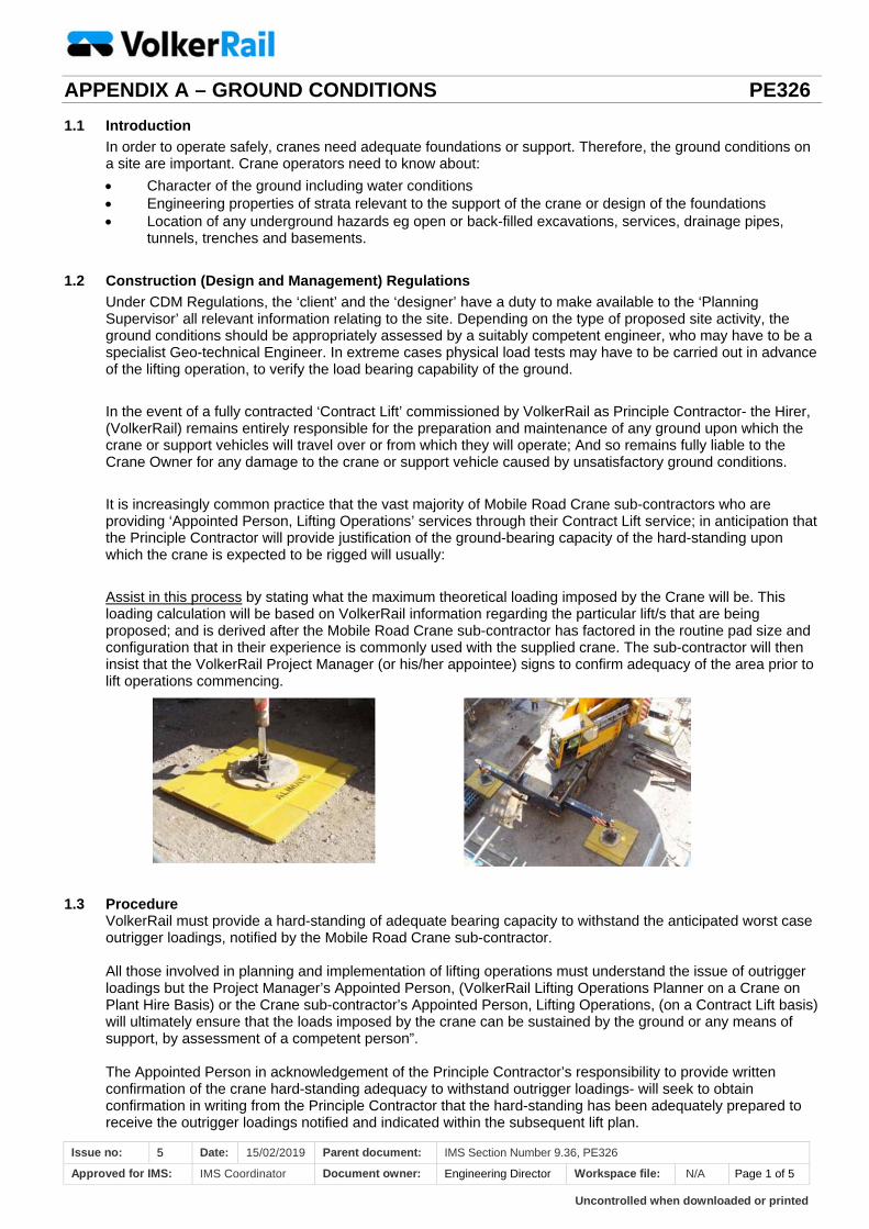
It is increasingly common practice that the vast majority of Mobile Road Crane sub-contractors who are providing ‘Appointed Person, Lifting Operations’ services through their Contract Lift service; in anticipation that the Principle Contractor will provide justification of the ground-bearing capacity of the hard-standing upon which the crane is expected to be rigged will usually:
Assist in this process by stating what the maximum theoretical loading imposed by the Crane will be. This loading calculation will be based on VolkerRail information regarding the particular lift/s that are being proposed; and is derived after the Mobile Road Crane sub-contractor has factored in the routine pad size and configuration that in their experience is commonly used with the supplied crane. The sub-contractor will then insist that the VolkerRail Project Manager (or his/her appointee) signs to confirm adequacy of the area prior to lift operations commencing.
1.3 Procedure VolkerRail must provide a hard-standing of adequate bearing capacity to withstand the anticipated worst case outrigger loadings, notified by the Mobile Road Crane sub-contractor.
All those involved in planning and implementation of lifting operations must understand the issue of outrigger loadings but the Project Manager’s Appointed Person, (VolkerRail Lifting Operations Planner on a Crane on Plant Hire Basis) or the Crane sub-contractor’s Appointed Person, Lifting Operations, (on a Contract Lift basis) will ultimately ensure that the loads imposed by the crane can be sustained by the ground or any means of support, by assessment of a competent person”.
The Appointed Person in acknowledgement of the Principle Contractor’s responsibility to provide written confirmation of the crane hard-standing adequacy to withstand outrigger loadings- will seek to obtain confirmation in writing from the Principle Contractor that the hard-standing has been adequately prepared to receive the outrigger loadings notified and indicated within the subsequent lift plan.
Uncontrolled when downloaded or printed
APPENDIX A – GROUND CONDITIONS PE326
Issue no: 5 Date: 15/02/2019 Parent document: IMS Section Number 9.36, PE326
Approved for IMS: IMS Coordinator Document owner: Engineering Director Workspace file: N/A Page 2 of 5
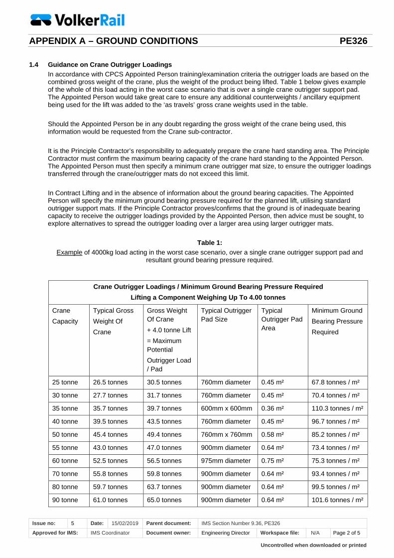
1.4 Guidance on Crane Outrigger Loadings
In accordance with CPCS Appointed Person training/examination criteria the outrigger loads are based on the combined gross weight of the crane, plus the weight of the product being lifted. Table 1 below gives example of the whole of this load acting in the worst case scenario that is over a single crane outrigger support pad. The Appointed Person would take great care to ensure any additional counterweights / ancillary equipment being used for the lift was added to the ‘as travels’ gross crane weights used in the table.
Should the Appointed Person be in any doubt regarding the gross weight of the crane being used, this information would be requested from the Crane sub-contractor.
It is the Principle Contractor’s responsibility to adequately prepare the crane hard standing area. The Principle Contractor must confirm the maximum bearing capacity of the crane hard standing to the Appointed Person. The Appointed Person must then specify a minimum crane outrigger mat size, to ensure the outrigger loadings transferred through the crane/outrigger mats do not exceed this limit.
In Contract Lifting and in the absence of information about the ground bearing capacities. The Appointed Person will specify the minimum ground bearing pressure required for the planned lift, utilising standard outrigger support mats. If the Principle Contractor proves/confirms that the ground is of inadequate bearing capacity to receive the outrigger loadings provided by the Appointed Person, then advice must be sought, to explore alternatives to spread the outrigger loading over a larger area using larger outrigger mats.
Table 1:
Example of 4000kg load acting in the worst case scenario, over a single crane outrigger support pad and resultant ground bearing pressure required.
Crane Outrigger Loadings / Minimum Ground Bearing Pressure Required
Lifting a Component Weighing Up To 4.00 tonnes
Crane
Capacity
Typical Gross
Weight Of
Crane
Gross Weight Of Crane
+ 4.0 tonne Lift
= Maximum Potential
Outrigger Load / Pad
Typical Outrigger Pad Size
Typical Outrigger Pad Area
Minimum Ground
Bearing Pressure
Required
25 tonne 26.5 tonnes 30.5 tonnes 760mm diameter 0.45 m² 67.8 tonnes / m²
30 tonne 27.7 tonnes 31.7 tonnes 760mm diameter 0.45 m² 70.4 tonnes / m²
35 tonne 35.7 tonnes 39.7 tonnes 600mm x 600mm 0.36 m² 110.3 tonnes / m²
40 tonne 39.5 tonnes 43.5 tonnes 760mm diameter 0.45 m² 96.7 tonnes / m²
50 tonne 45.4 tonnes 49.4 tonnes 760mm x 760mm 0.58 m² 85.2 tonnes / m²
55 tonne 43.0 tonnes 47.0 tonnes 900mm diameter 0.64 m² 73.4 tonnes / m²
60 tonne 52.5 tonnes 56.5 tonnes 975mm diameter 0.75 m² 75.3 tonnes / m²
70 tonne 55.8 tonnes 59.8 tonnes 900mm diameter 0.64 m² 93.4 tonnes / m²
80 tonne 59.7 tonnes 63.7 tonnes 900mm diameter 0.64 m² 99.5 tonnes / m²
90 tonne 61.0 tonnes 65.0 tonnes 900mm diameter 0.64 m² 101.6 tonnes / m²
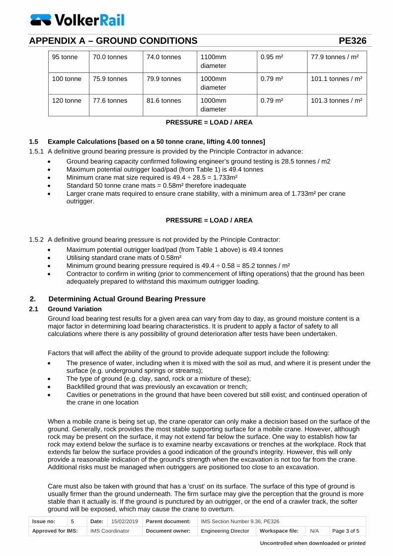
Uncontrolled when downloaded or printed
APPENDIX A – GROUND CONDITIONS PE326
Issue no: 5 Date: 15/02/2019 Parent document: IMS Section Number 9.36, PE326
Approved for IMS: IMS Coordinator Document owner: Engineering Director Workspace file: N/A Page 3 of 5
95 tonne 70.0 tonnes 74.0 tonnes 1100mm diameter
0.95 m² 77.9 tonnes / m²
100 tonne 75.9 tonnes 79.9 tonnes 1000mm diameter
0.79 m² 101.1 tonnes / m²
120 tonne 77.6 tonnes 81.6 tonnes 1000mm diameter
0.79 m² 101.3 tonnes / m²
PRESSURE = LOAD / AREA
1.5 Example Calculations [based on a 50 tonne crane, lifting 4.00 tonnes]
1.5.1 A definitive ground bearing pressure is provided by the Principle Contractor in advance:
Ground bearing capacity confirmed following engineer’s ground testing is 28.5 tonnes / m2 Maximum potential outrigger load/pad (from Table 1) is 49.4 tonnes Minimum crane mat size required is 49.4 ÷ 28.5 = 1.733m² Standard 50 tonne crane mats = 0.58m² therefore inadequate Larger crane mats required to ensure crane stability, with a minimum area of 1.733m² per crane
outrigger.
PRESSURE = LOAD / AREA
1.5.2 A definitive ground bearing pressure is not provided by the Principle Contractor:
Maximum potential outrigger load/pad (from Table 1 above) is 49.4 tonnes Utilising standard crane mats of 0.58m² Minimum ground bearing pressure required is 49.4 ÷ 0.58 = 85.2 tonnes / m² Contractor to confirm in writing (prior to commencement of lifting operations) that the ground has been
adequately prepared to withstand this maximum outrigger loading.
2. Determining Actual Ground Bearing Pressure2.1 Ground Variation
Ground load bearing test results for a given area can vary from day to day, as ground moisture content is a major factor in determining load bearing characteristics. It is prudent to apply a factor of safety to all calculations where there is any possibility of ground deterioration after tests have been undertaken.
Factors that will affect the ability of the ground to provide adequate support include the following:
The presence of water, including when it is mixed with the soil as mud, and where it is present under thesurface (e.g. underground springs or streams);
The type of ground (e.g. clay, sand, rock or a mixture of these); Backfilled ground that was previously an excavation or trench; Cavities or penetrations in the ground that have been covered but still exist; and continued operation of
the crane in one location
When a mobile crane is being set up, the crane operator can only make a decision based on the surface of the ground. Generally, rock provides the most stable supporting surface for a mobile crane. However, although rock may be present on the surface, it may not extend far below the surface. One way to establish how far rock may extend below the surface is to examine nearby excavations or trenches at the workplace. Rock that extends far below the surface provides a good indication of the ground's integrity. However, this will only provide a reasonable indication of the ground's strength when the excavation is not too far from the crane. Additional risks must be managed when outriggers are positioned too close to an excavation.
Care must also be taken with ground that has a 'crust' on its surface. The surface of this type of ground is usually firmer than the ground underneath. The firm surface may give the perception that the ground is more stable than it actually is. If the ground is punctured by an outrigger, or the end of a crawler track, the softer ground will be exposed, which may cause the crane to overturn.
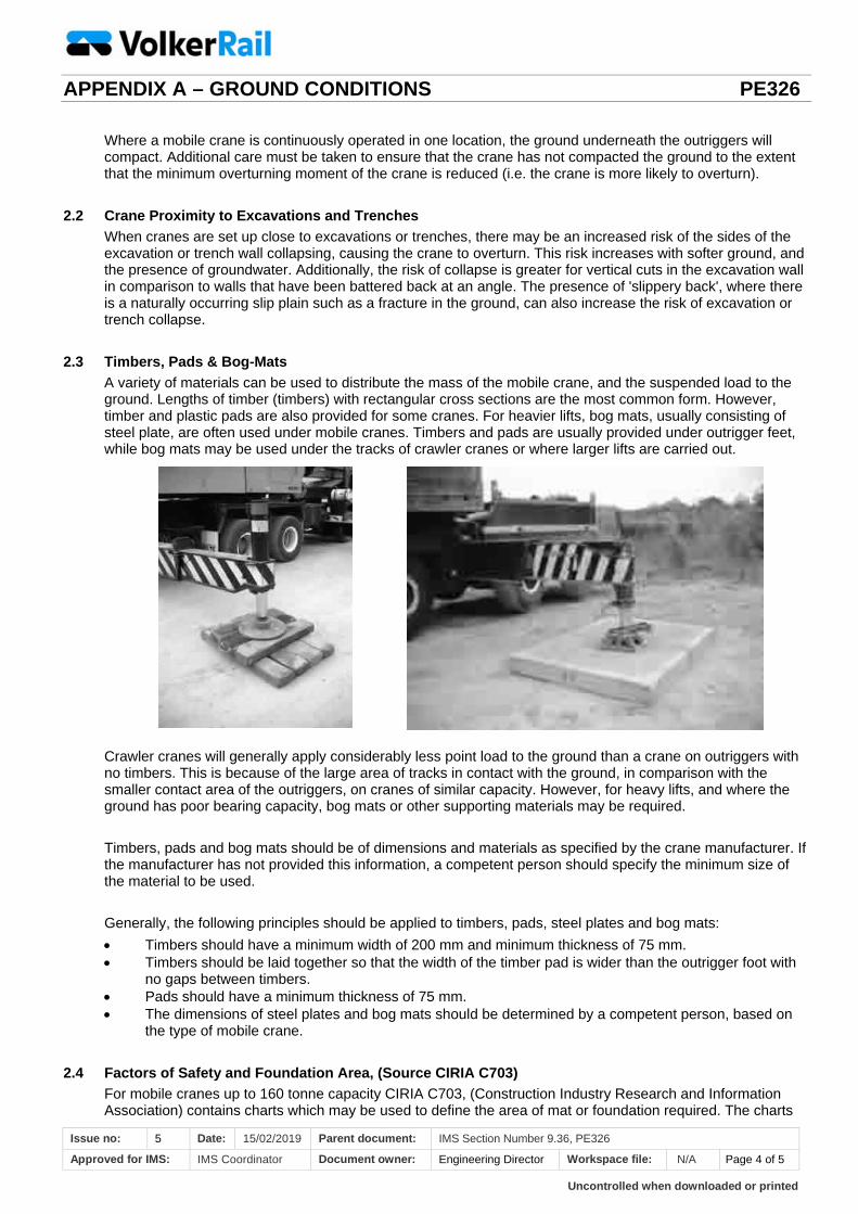
Uncontrolled when downloaded or printed
APPENDIX A – GROUND CONDITIONS PE326
Issue no: 5 Date: 15/02/2019 Parent document: IMS Section Number 9.36, PE326
Approved for IMS: IMS Coordinator Document owner: Engineering Director Workspace file: N/A Page 4 of 5
Where a mobile crane is continuously operated in one location, the ground underneath the outriggers will compact. Additional care must be taken to ensure that the crane has not compacted the ground to the extent that the minimum overturning moment of the crane is reduced (i.e. the crane is more likely to overturn).
2.2 Crane Proximity to Excavations and Trenches
When cranes are set up close to excavations or trenches, there may be an increased risk of the sides of the excavation or trench wall collapsing, causing the crane to overturn. This risk increases with softer ground, and the presence of groundwater. Additionally, the risk of collapse is greater for vertical cuts in the excavation wall in comparison to walls that have been battered back at an angle. The presence of 'slippery back', where there is a naturally occurring slip plain such as a fracture in the ground, can also increase the risk of excavation or trench collapse.
2.3 Timbers, Pads & Bog-Mats
A variety of materials can be used to distribute the mass of the mobile crane, and the suspended load to the ground. Lengths of timber (timbers) with rectangular cross sections are the most common form. However, timber and plastic pads are also provided for some cranes. For heavier lifts, bog mats, usually consisting of steel plate, are often used under mobile cranes. Timbers and pads are usually provided under outrigger feet, while bog mats may be used under the tracks of crawler cranes or where larger lifts are carried out.
Crawler cranes will generally apply considerably less point load to the ground than a crane on outriggers with no timbers. This is because of the large area of tracks in contact with the ground, in comparison with the smaller contact area of the outriggers, on cranes of similar capacity. However, for heavy lifts, and where the ground has poor bearing capacity, bog mats or other supporting materials may be required.
Timbers, pads and bog mats should be of dimensions and materials as specified by the crane manufacturer. If the manufacturer has not provided this information, a competent person should specify the minimum size of the material to be used.
Generally, the following principles should be applied to timbers, pads, steel plates and bog mats:
Timbers should have a minimum width of 200 mm and minimum thickness of 75 mm. Timbers should be laid together so that the width of the timber pad is wider than the outrigger foot with
no gaps between timbers. Pads should have a minimum thickness of 75 mm. The dimensions of steel plates and bog mats should be determined by a competent person, based on
the type of mobile crane.
2.4 Factors of Safety and Foundation Area, (Source CIRIA C703)
For mobile cranes up to 160 tonne capacity CIRIA C703, (Construction Industry Research and Information Association) contains charts which may be used to define the area of mat or foundation required. The charts
Uncontrolled when downloaded or printed
APPENDIX A – GROUND CONDITIONS PE326
Issue no: 5 Date: 15/02/2019 Parent document: IMS Section Number 9.36, PE326
Approved for IMS: IMS Coordinator Document owner: Engineering Director Workspace file: N/A Page 5 of 5
give foundation areas for a range of Factors of Safety against bearing failure and excessive settlement of the ground.
FOS of 3.0 is more normally used for permanent works foundations and will give a conservative size offoundation area. It should be used for outrigger foundations where minimum ground information is available, where soils are variable or where minor settlements could be critical to a precision lifting and placing operation.
FOS of 2.0 is adequate for most situations FOS of 1.5 is the absolute minimum and should only be used where ground conditions have been
accurately identified under the guidance of an experienced geotechnical engineer.
2.5 Outrigger Foundations
Various methods of providing an increased area of foundation under the outrigger pad may be used. It is generally the responsibility of the user/site to supply these materials, unless otherwise agreed with the crane hirer.
Foundation materials must be designed to spread the load over the area required. The material used to form the spreader mat must be strong enough to spread the outrigger load over the full foundation area. Design calculations are required to be sure of the load that can be safely carried. Even without calculation, commonsense dictates that some arrangements are totally unsuitable. For example, a sheet of ply or broken scaffold board may provide the foundation area required but would have insufficient strength to spread the load.
2.6 Further Reading
Appendix A1 of CIRIA C703 ’Crane Stability on Site’ illustrates typical calculations for mobile crane loadspreading through timber sleepers
VolkerRail Plant Kirow Team has specialist, tabulated formulae for similar calculation for a range oftypical rail crane operations

Uncontrolled when downloaded or printed
APPENDIX B – SITE SPECIFIC MACHINE WORK PLAN FORM PE326F01 SAMPLES PE326
Issue no: 5 Date: 15/02/2019 Parent document: IMS Section Number 9.36
Approved for IMS: IMS Coordinator Document owner: Engineering Director Workspace file: N/A Page 1 of 2
Part 1: Machine and Access Information
1
Details of Plant Operating License Holder & Safety Certification
1.1 OTP and Crane Controlled OTMs:
Machines Identified for these works:
Supplier: Machine: Serial No OTP Group: EAC valid
1.2 ‘Civils’ – Non-Rail Mounted Self-Propelled Machines:
Machines Identified for these works:
Supplier: Machine: Machine Type
1.3 Access Arrangements:
1.31 Access & Egress Route Assessment and description:
1.32 On, off and cross-tracking point/s Assessment and description:
1.33 RRV, RVE 0007 Arrangements: (Outcome from 1.22)
Part 2: Site Description, Layout & Dimensions
2.1 General Site Description:
2.2 Lines and Roads affected with possession and closure information
2.3 Site Preparation Arrangements:
2.4 Traffic Management, working / reversing / loading zones:
2.5 Minimum Horizontal & Vertical off-sets:
2.6 Machine working area limits / separation distance:
2.7 Areas of consideration for personnel exclusion:
2.8 Maximum Cant and Gradient Values & Demarcation:
Site Specific Machine Work Plan
(Parts 1 – 4) LOCATION DATE DOCUMENT No
This document is to be held by all Banks-man/Machine Controllers and Crane Supervisors/Crane Controllers and
Engineering/Safe Work Leader 2 & Site Supervisors
VRCC (Control Centre) Tel: 01302 791187 Contents:
Part 1: Machine and Access Information
Part 2: Site Description, layout & dimensions
Part 3: Machine Working Activity and Operational Arrangements
Part 4: Site-specific hazards & control measures
Associated Lifting Operations Documents – (delete as applicable)
Part 5: OTP and Controlled OTM - CC & TL - Crane Lift Plans
Part 6: Tele-Handler, Fork Lift Truck & Lorry Loader - Crane Lift Plans
Part 7: MEWP Operation – Machine Work Plan
Enclosures - (delete as applicable)
1. VolkerRail Form PE326F08 is an enhanced version of COP/0016
2. Relevant latest HSQE or Engineering Alerts
3. Engineering Brief PE3523 - Send and Receive Procedure
Note: Machine Operation Planning can be carried out by the Appointed Person/Lifting Operations Planner
Machine operations planned by:
Position: Name: Date: Signature:
Appointed Person/Lifting Operations Planner
Certification No: Name: Date: Signature:
Project Management Contact Details
NAME: Contact Details: Position:
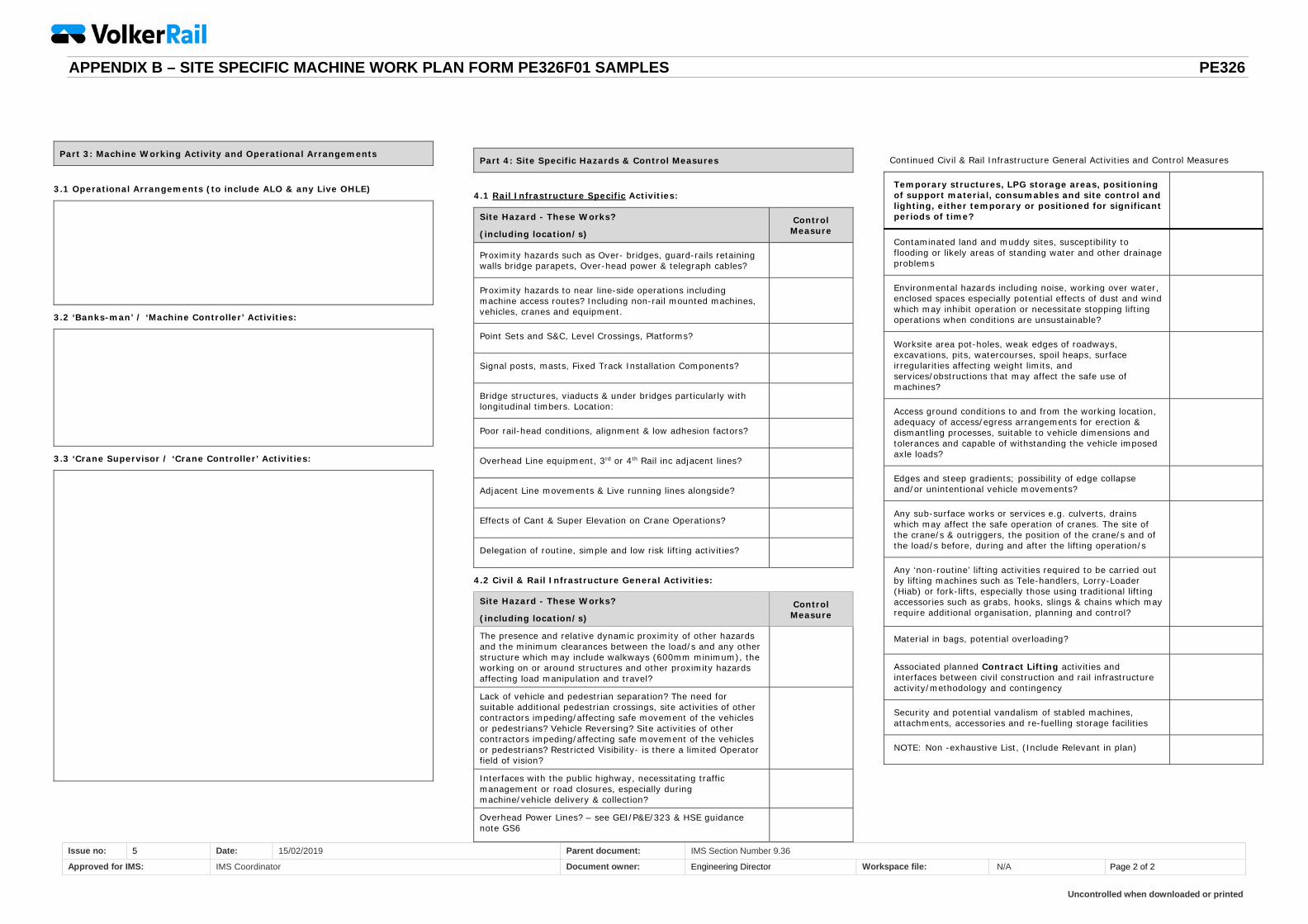
Uncontrolled when downloaded or printed
APPENDIX B – SITE SPECIFIC MACHINE WORK PLAN FORM PE326F01 SAMPLES PE326
Issue no: 5 Date: 15/02/2019 Parent document: IMS Section Number 9.36
Approved for IMS: IMS Coordinator Document owner: Engineering Director Workspace file: N/A Page 2 of 2
Part 3: Machine Working Activity and Operational Arrangements
3.1 Operational Arrangements (to include ALO & any Live OHLE)
3.2 ‘Banks-man’ / ‘Machine Controller’ Activities:
3.3 ‘Crane Supervisor / ‘Crane Controller’ Activities:
Part 4: Site Specific Hazards & Control Measures
4.1 Rail Infrastructure Specific Activities:
Site Hazard - These Works?
(including location/s) Control Measure
Proximity hazards such as Over- bridges, guard-rails retaining walls bridge parapets, Over-head power & telegraph cables?
Proximity hazards to near line-side operations including machine access routes? Including non-rail mounted machines, vehicles, cranes and equipment.
Point Sets and S&C, Level Crossings, Platforms?
Signal posts, masts, Fixed Track Installation Components?
Bridge structures, viaducts & under bridges particularly with longitudinal timbers. Location:
Poor rail-head conditions, alignment & low adhesion factors?
Overhead Line equipment, 3rd or 4th Rail inc adjacent lines?
Adjacent Line movements & Live running lines alongside?
Effects of Cant & Super Elevation on Crane Operations?
Delegation of routine, simple and low risk lifting activities?
4.2 Civil & Rail Infrastructure General Activities:
Site Hazard - These Works?
(including location/s) Control Measure
The presence and relative dynamic proximity of other hazards and the minimum clearances between the load/s and any other structure which may include walkways (600mm minimum), the working on or around structures and other proximity hazards affecting load manipulation and travel?
Lack of vehicle and pedestrian separation? The need for suitable additional pedestrian crossings, site activities of other contractors impeding/affecting safe movement of the vehicles or pedestrians? Vehicle Reversing? Site activities of other contractors impeding/affecting safe movement of the vehicles or pedestrians? Restricted Visibility- is there a limited Operator field of vision?
Interfaces with the public highway, necessitating traffic management or road closures, especially during machine/vehicle delivery & collection?
Overhead Power Lines? – see GEI/P&E/323 & HSE guidance note GS6
Continued Civil & Rail Infrastructure General Activities and Control Measures
Temporary structures, LPG storage areas, positioning of support material, consumables and site control and lighting, either temporary or positioned for significant periods of time?
Contaminated land and muddy sites, susceptibility to flooding or likely areas of standing water and other drainage problems
Environmental hazards including noise, working over water, enclosed spaces especially potential effects of dust and wind which may inhibit operation or necessitate stopping lifting operations when conditions are unsustainable?
Worksite area pot-holes, weak edges of roadways, excavations, pits, watercourses, spoil heaps, surface irregularities affecting weight limits, and services/obstructions that may affect the safe use of machines?
Access ground conditions to and from the working location, adequacy of access/egress arrangements for erection & dismantling processes, suitable to vehicle dimensions and tolerances and capable of withstanding the vehicle imposed axle loads?
Edges and steep gradients; possibility of edge collapse and/or unintentional vehicle movements?
Any sub-surface works or services e.g. culverts, drains which may affect the safe operation of cranes. The site of the crane/s & outriggers, the position of the crane/s and of the load/s before, during and after the lifting operation/s
Any ‘non-routine’ lifting activities required to be carried out by lifting machines such as Tele-handlers, Lorry-Loader (Hiab) or fork-lifts, especially those using traditional lifting accessories such as grabs, hooks, slings & chains which may require additional organisation, planning and control?
Material in bags, potential overloading?
Associated planned Contract Lifting activities and interfaces between civil construction and rail infrastructure activity/methodology and contingency
Security and potential vandalism of stabled machines, attachments, accessories and re-fuelling storage facilities
NOTE: Non -exhaustive List, (Include Relevant in plan)

Uncontrolled when downloaded or printed
APPENDIX C – OTM AND OTP CONTROLLER COMPETENCY IDENTIFICATION PE326
Issue no: 5 Date: 15/02/2019 Parent document: IMS Section Number 9.36
Approved for IMS: IMS coordinator Document owner: Engineering Director Workspace file: N/A Page 1 of 2
Modular Assessment:
The Network Rail / Sentinel OTP and OTM Controller Competency framework is formulated by the Machine Controller, (MC) Crane Controller (CC) and Crane Controller – Tandem Lifting (TL) continuous modular assessment of specific ‘Host Machine Types’ and ‘Miscellaneous Equipments’. The following reference list identifies the competency modules that identify suitable OTP and Crane Controlled OTM Controllers for specific ‘Host Machines’:-
Machine Controller Machine Specific – All candidates must be assessed in the OTP core module.
MC RRV Module 2 Excavator
MC RRV Module 5 Dumper
MC RRV Module 6 Lorry
MC RRV Module 7 Land Rover
MC RRV Module 8 ATUV
MC RRV Module 9 MEWP
MC RRV Module 10 Dozer
MC RMMM Module 1 Group 1 Packers, etc
MC RMMM Module 1 Group 2 Personnel/Inspections Carts
MC RMMM Module 1 Group 4 Access Platform
MC RMMM Module 1 Group 6 Track Gopher
MC RMMM Module 1 Group 7 Sleeper Changer
MC RMMM Module 1 Group 8 Mini Tamper
MC RMMM Module 1 Group 10 Bruff Rail Threader
Crane Controller Machine Specific – All candidates must be assessed in the OTP core module
CC RRV Module 3 Excavator Crane
CC TL RRV Module 4 Excavator Tandem Lift
CC RMMM Module 1 Group 3 Panel Layers
CC RMMM Module 1 Group 9 Single Line Gantries
OTM Crane Controller Machine Specific –
CC OTM Module 1 TRAMM, TASC & MPV
CC OTM Module 2 GPC and/or TRM
CC TL OTM Module 3 Rail Crane - Tandem Lifting
CC OTM Module 4 Kirow 250/810/1200 Rail Cranes
CC OTM Module 5 Delivery Train / Unloading Cranes

Uncontrolled when downloaded or printed
APPENDIX C – OTM AND OTP CONTROLLER COMPETENCY IDENTIFICATION PE326
Issue no: 5 Date: 15/02/2019 Parent document: IMS Section Number 9.36
Approved for IMS: IMS coordinator Document owner: Engineering Director Workspace file: N/A Page 2 of 2
Host Machines such as ‘Lorry’ and ‘Dumper’ can be fitted with ‘Miscellaneous Equipments’ such as Knuckle Booms. For instance a MEWP may be a host machine, (where it is a self-propelled RRV) but it may also be just an item of miscellaneous equipment - fitted to a ‘Dumper’ or ‘Lorry’ etc.
Some of these items may require a CC to position on rail line, but may, (depending on regular use) be controlled by an MC. These items, such as a Trailer fitted with a Ballast Box, or Personnel Carrier are classed as Machine Controller miscellaneous equipments.
Machine Controller Miscellaneous Equipment:-
MC Misc Module 2 Group 1 Vegetation Control
MC Misc Module 2 Group 3 Tamping Head
MC Misc Module 2 Group 4 Fast Clipper
MC Misc Module 2 Group 5 Rail Cropper
MC Misc Module 2 Group 6 Trailers
MC Misc Module 2 Group 7 Sleeper Changer
MC Misc Module 2 Group 9 Drilling Rig
MC Misc Module 3 MEWP
Some items of Miscellaneous Equipment must be ‘Crane Controlled’ because of their operational characteristics, and are deemed to be Crane Controller, (CC) miscellaneous equipments.
Crane Controller Miscellaneous Equipment:-
CC Misc Module 1 Knuckle Boom Crane
CC Misc Module 2 Group 2 Ballast Broom
CC Misc Module 2 Group 8 Excavac
CC Misc Module 2 Group 10 Rail Thimble
CC Misc Module 2 Group 11 Power Lifting Equipment
Important Note:
Individual host machine types and miscellaneous equipment, (occasionally termed ‘attachments’ shall be displayed on a ‘Secure Counterpart’ which supports the Controller Sentinel Card but:-
Competence for machine variations (such as differing manufacturer etc) and attachments not within the scheme module matrix, fall outside of this scheme and remain entirely within the arrangements of the Machine/Crane Controller’s employer.
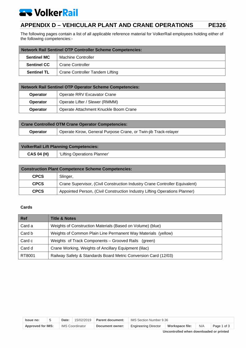
Uncontrolled when downloaded or printed
APPENDIX D – VEHICULAR PLANT AND CRANE OPERATIONS PE326
Issue no: 5 Date: 15/02/2019 Parent document: IMS Section Number 9.36
Approved for IMS: IMS Coordinator Document owner: Engineering Director Workspace file: N/A Page 1 of 3
The following pages contain a list of all applicable reference material for VolkerRail employees holding either of the following competencies:-
Network Rail Sentinel OTP Controller Scheme Competencies:
Sentinel MC Machine Controller
Sentinel CC Crane Controller
Sentinel TL Crane Controller Tandem Lifting
Network Rail Sentinel OTP Operator Scheme Competencies:
Operator Operate RRV Excavator Crane
Operator Operate Lifter / Slewer (RMMM)
Operator Operate Attachment Knuckle Boom Crane
Crane Controlled OTM Crane Operator Competencies:
Operator Operate Kirow, General Purpose Crane, or Twin-jib Track-relayer
VolkerRail Lift Planning Competencies:
CAS 04 (H) ‘Lifting Operations Planner’
Construction Plant Competence Scheme Competencies:
CPCS Slinger,
CPCS Crane Supervisor, (Civil Construction Industry Crane Controller Equivalent)
CPCS Appointed Person, (Civil Construction Industry Lifting Operations Planner)
Cards
Ref Title & Notes
Card a Weights of Construction Materials (Based on Volume) (blue)
Card b Weights of Common Plain Line Permanent Way Materials (yellow)
Card c Weights of Track Components – Grooved Rails (green)
Card d Crane Working, Weights of Ancillary Equipment (lilac)
RT8001 Railway Safety & Standards Board Metric Conversion Card (12/03)
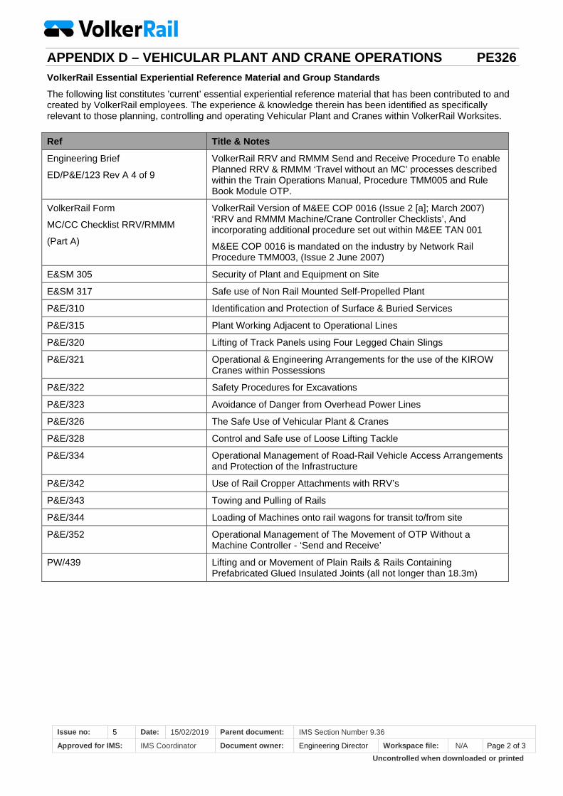
Uncontrolled when downloaded or printed
APPENDIX D – VEHICULAR PLANT AND CRANE OPERATIONS PE326
Issue no: 5 Date: 15/02/2019 Parent document: IMS Section Number 9.36
Approved for IMS: IMS Coordinator Document owner: Engineering Director Workspace file: N/A Page 2 of 3
VolkerRail Essential Experiential Reference Material and Group Standards
The following list constitutes ’current’ essential experiential reference material that has been contributed to and created by VolkerRail employees. The experience & knowledge therein has been identified as specifically relevant to those planning, controlling and operating Vehicular Plant and Cranes within VolkerRail Worksites.
Ref Title & Notes
Engineering Brief
ED/P&E/123 Rev A 4 of 9
VolkerRail RRV and RMMM Send and Receive Procedure To enable Planned RRV & RMMM ‘Travel without an MC’ processes described within the Train Operations Manual, Procedure TMM005 and Rule Book Module OTP.
VolkerRail Form
MC/CC Checklist RRV/RMMM
(Part A)
VolkerRail Version of M&EE COP 0016 (Issue 2 [a]; March 2007) ‘RRV and RMMM Machine/Crane Controller Checklists’, And incorporating additional procedure set out within M&EE TAN 001
M&EE COP 0016 is mandated on the industry by Network Rail Procedure TMM003, (Issue 2 June 2007)
E&SM 305 Security of Plant and Equipment on Site
E&SM 317 Safe use of Non Rail Mounted Self-Propelled Plant
P&E/310 Identification and Protection of Surface & Buried Services
P&E/315 Plant Working Adjacent to Operational Lines
P&E/320 Lifting of Track Panels using Four Legged Chain Slings
P&E/321 Operational & Engineering Arrangements for the use of the KIROW Cranes within Possessions
P&E/322 Safety Procedures for Excavations
P&E/323 Avoidance of Danger from Overhead Power Lines
P&E/326 The Safe Use of Vehicular Plant & Cranes
P&E/328 Control and Safe use of Loose Lifting Tackle
P&E/334 Operational Management of Road-Rail Vehicle Access Arrangements and Protection of the Infrastructure
P&E/342 Use of Rail Cropper Attachments with RRV’s
P&E/343 Towing and Pulling of Rails
P&E/344 Loading of Machines onto rail wagons for transit to/from site
P&E/352 Operational Management of The Movement of OTP Without a Machine Controller - ‘Send and Receive’
PW/439 Lifting and or Movement of Plain Rails & Rails Containing Prefabricated Glued Insulated Joints (all not longer than 18.3m)
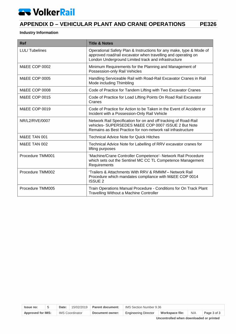
Uncontrolled when downloaded or printed
APPENDIX D – VEHICULAR PLANT AND CRANE OPERATIONS PE326
Issue no: 5 Date: 15/02/2019 Parent document: IMS Section Number 9.36
Approved for IMS: IMS Coordinator Document owner: Engineering Director Workspace file: N/A Page 3 of 3
Industry Information
Ref Title & Notes
LUL/ Tubelines Operational Safety Plan & Instructions for any make, type & Mode of approved road/rail excavator when travelling and operating on London Underground Limited track and infrastructure
M&EE COP 0002 Minimum Requirements for the Planning and Management of Possession-only Rail Vehicles
M&EE COP 0005 Handling Serviceable Rail with Road-Rail Excavator Cranes in Rail Mode including Thimbling
M&EE COP 0008 Code of Practice for Tandem Lifting with Two Excavator Cranes
M&EE COP 0015 Code of Practice for Load Lifting Points On Road Rail Excavator Cranes
M&EE COP 0019 Code of Practice for Action to be Taken in the Event of Accident or Incident with a Possession-Only Rail Vehicle
NR/L2/RVE/0007 Network Rail Specification for on and off tracking of Road-Rail vehicles- SUPERSEDES M&EE COP 0007 ISSUE 2 But Note Remains as Best Practice for non-network rail infrastructure
M&EE TAN 001 Technical Advice Note for Quick Hitches
M&EE TAN 002 Technical Advice Note for Labelling of RRV excavator cranes for lifting purposes
Procedure TMM001 ‘Machine/Crane Controller Competence’- Network Rail Procedure which sets out the Sentinel MC CC TL Competence Management Requirements
Procedure TMM002 ‘Trailers & Attachments With RRV & RMMM’– Network Rail Procedure which mandates compliance with M&EE COP 0014 ISSUE 2
Procedure TMM005 Train Operations Manual Procedure - Conditions for On Track Plant Travelling Without a Machine Controller
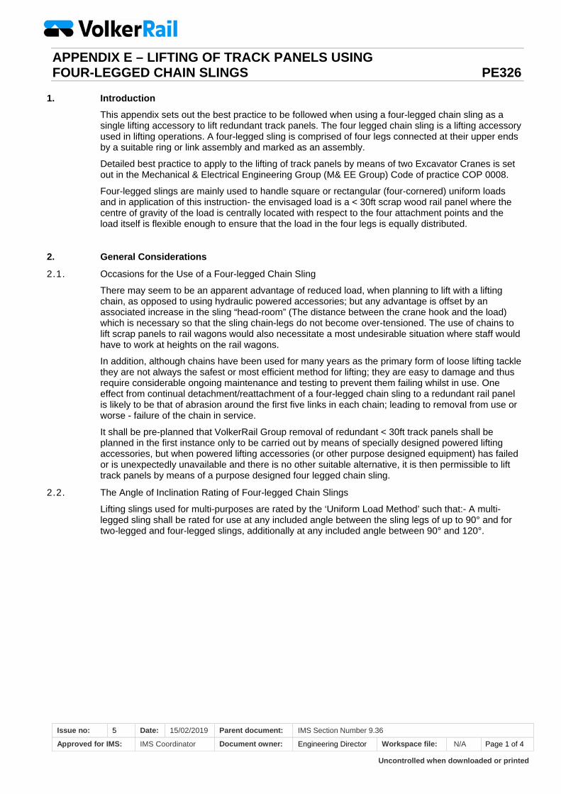
Uncontrolled when downloaded or printed
APPENDIX E – LIFTING OF TRACK PANELS USING FOUR-LEGGED CHAIN SLINGS PE326
Issue no: 5 Date: 15/02/2019 Parent document: IMS Section Number 9.36
Approved for IMS: IMS Coordinator Document owner: Engineering Director Workspace file: N/A Page 1 of 4
1. Introduction
This appendix sets out the best practice to be followed when using a four-legged chain sling as a single lifting accessory to lift redundant track panels. The four legged chain sling is a lifting accessory used in lifting operations. A four-legged sling is comprised of four legs connected at their upper ends by a suitable ring or link assembly and marked as an assembly.
Detailed best practice to apply to the lifting of track panels by means of two Excavator Cranes is set out in the Mechanical & Electrical Engineering Group (M& EE Group) Code of practice COP 0008.
Four-legged slings are mainly used to handle square or rectangular (four-cornered) uniform loads and in application of this instruction- the envisaged load is a < 30ft scrap wood rail panel where the centre of gravity of the load is centrally located with respect to the four attachment points and the load itself is flexible enough to ensure that the load in the four legs is equally distributed.
2. General Considerations
2.1. Occasions for the Use of a Four-legged Chain Sling
There may seem to be an apparent advantage of reduced load, when planning to lift with a lifting chain, as opposed to using hydraulic powered accessories; but any advantage is offset by an associated increase in the sling “head-room” (The distance between the crane hook and the load) which is necessary so that the sling chain-legs do not become over-tensioned. The use of chains to lift scrap panels to rail wagons would also necessitate a most undesirable situation where staff would have to work at heights on the rail wagons.
In addition, although chains have been used for many years as the primary form of loose lifting tackle they are not always the safest or most efficient method for lifting; they are easy to damage and thus require considerable ongoing maintenance and testing to prevent them failing whilst in use. One effect from continual detachment/reattachment of a four-legged chain sling to a redundant rail panel is likely to be that of abrasion around the first five links in each chain; leading to removal from use or worse - failure of the chain in service.
It shall be pre-planned that VolkerRail Group removal of redundant < 30ft track panels shall be planned in the first instance only to be carried out by means of specially designed powered lifting accessories, but when powered lifting accessories (or other purpose designed equipment) has failed or is unexpectedly unavailable and there is no other suitable alternative, it is then permissible to lift track panels by means of a purpose designed four legged chain sling.
2.2. The Angle of Inclination Rating of Four-legged Chain Slings
Lifting slings used for multi-purposes are rated by the ‘Uniform Load Method’ such that:- A multi-legged sling shall be rated for use at any included angle between the sling legs of up to 90° and for two-legged and four-legged slings, additionally at any included angle between 90° and 120°.
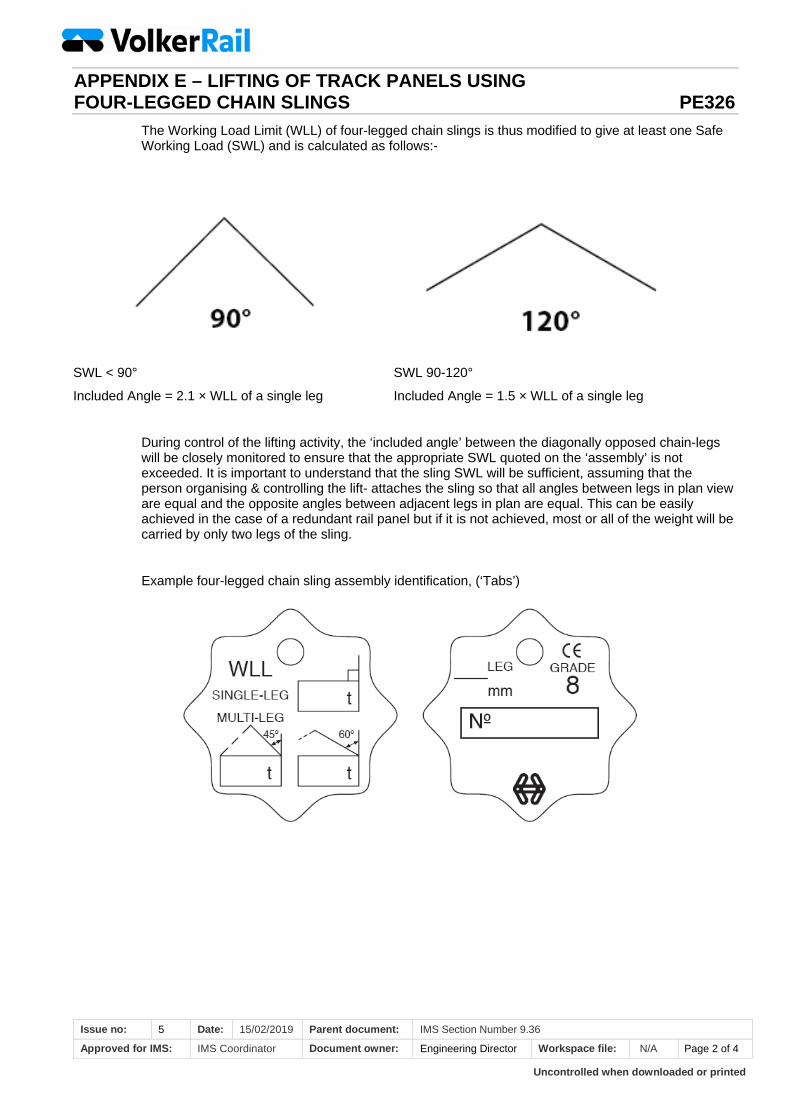
Uncontrolled when downloaded or printed
APPENDIX E – LIFTING OF TRACK PANELS USING FOUR-LEGGED CHAIN SLINGS PE326
Issue no: 5 Date: 15/02/2019 Parent document: IMS Section Number 9.36
Approved for IMS: IMS Coordinator Document owner: Engineering Director Workspace file: N/A Page 2 of 4
The Working Load Limit (WLL) of four-legged chain slings is thus modified to give at least one Safe Working Load (SWL) and is calculated as follows:-
SWL < 90°
Included Angle = 2.1 × WLL of a single leg
SWL 90-120°
Included Angle = 1.5 × WLL of a single leg
During control of the lifting activity, the ‘included angle’ between the diagonally opposed chain-legs will be closely monitored to ensure that the appropriate SWL quoted on the ‘assembly’ is not exceeded. It is important to understand that the sling SWL will be sufficient, assuming that the person organising & controlling the lift- attaches the sling so that all angles between legs in plan view are equal and the opposite angles between adjacent legs in plan are equal. This can be easily achieved in the case of a redundant rail panel but if it is not achieved, most or all of the weight will be carried by only two legs of the sling.
Example four-legged chain sling assembly identification, (‘Tabs’)
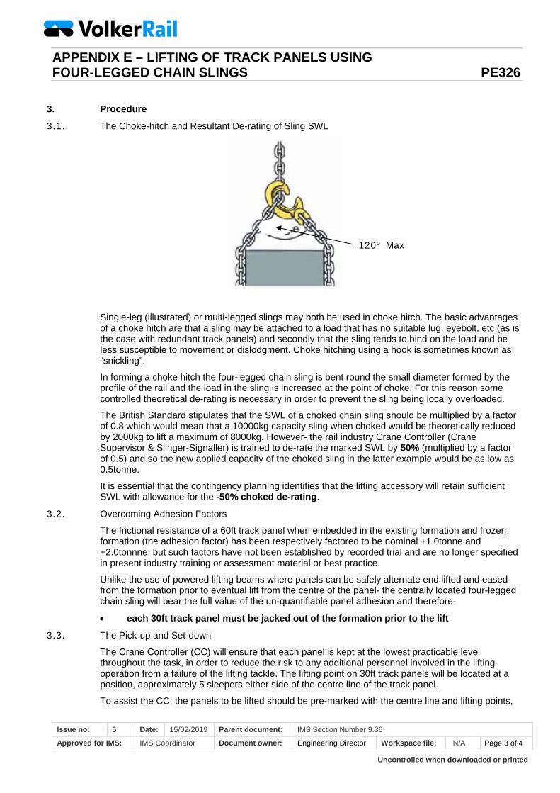
Uncontrolled when downloaded or printed
APPENDIX E – LIFTING OF TRACK PANELS USING FOUR-LEGGED CHAIN SLINGS PE326
Issue no: 5 Date: 15/02/2019 Parent document: IMS Section Number 9.36
Approved for IMS: IMS Coordinator Document owner: Engineering Director Workspace file: N/A Page 3 of 4
3. Procedure
3.1. The Choke-hitch and Resultant De-rating of Sling SWL
Single-leg (illustrated) or multi-legged slings may both be used in choke hitch. The basic advantages of a choke hitch are that a sling may be attached to a load that has no suitable lug, eyebolt, etc (as is the case with redundant track panels) and secondly that the sling tends to bind on the load and be less susceptible to movement or dislodgment. Choke hitching using a hook is sometimes known as “snickling”.
In forming a choke hitch the four-legged chain sling is bent round the small diameter formed by the profile of the rail and the load in the sling is increased at the point of choke. For this reason some controlled theoretical de-rating is necessary in order to prevent the sling being locally overloaded.
The British Standard stipulates that the SWL of a choked chain sling should be multiplied by a factor of 0.8 which would mean that a 10000kg capacity sling when choked would be theoretically reduced by 2000kg to lift a maximum of 8000kg. However- the rail industry Crane Controller (Crane Supervisor & Slinger-Signaller) is trained to de-rate the marked SWL by 50% (multiplied by a factor of 0.5) and so the new applied capacity of the choked sling in the latter example would be as low as 0.5tonne.
It is essential that the contingency planning identifies that the lifting accessory will retain sufficient SWL with allowance for the -50% choked de-rating.
3.2. Overcoming Adhesion Factors
The frictional resistance of a 60ft track panel when embedded in the existing formation and frozen formation (the adhesion factor) has been respectively factored to be nominal +1.0tonne and +2.0tonnne; but such factors have not been established by recorded trial and are no longer specified in present industry training or assessment material or best practice.
Unlike the use of powered lifting beams where panels can be safely alternate end lifted and eased from the formation prior to eventual lift from the centre of the panel- the centrally located four-legged chain sling will bear the full value of the un-quantifiable panel adhesion and therefore-
each 30ft track panel must be jacked out of the formation prior to the lift
3.3. The Pick-up and Set-down
The Crane Controller (CC) will ensure that each panel is kept at the lowest practicable level throughout the task, in order to reduce the risk to any additional personnel involved in the lifting operation from a failure of the lifting tackle. The lifting point on 30ft track panels will be located at a position, approximately 5 sleepers either side of the centre line of the track panel.
To assist the CC; the panels to be lifted should be pre-marked with the centre line and lifting points,
120o Max
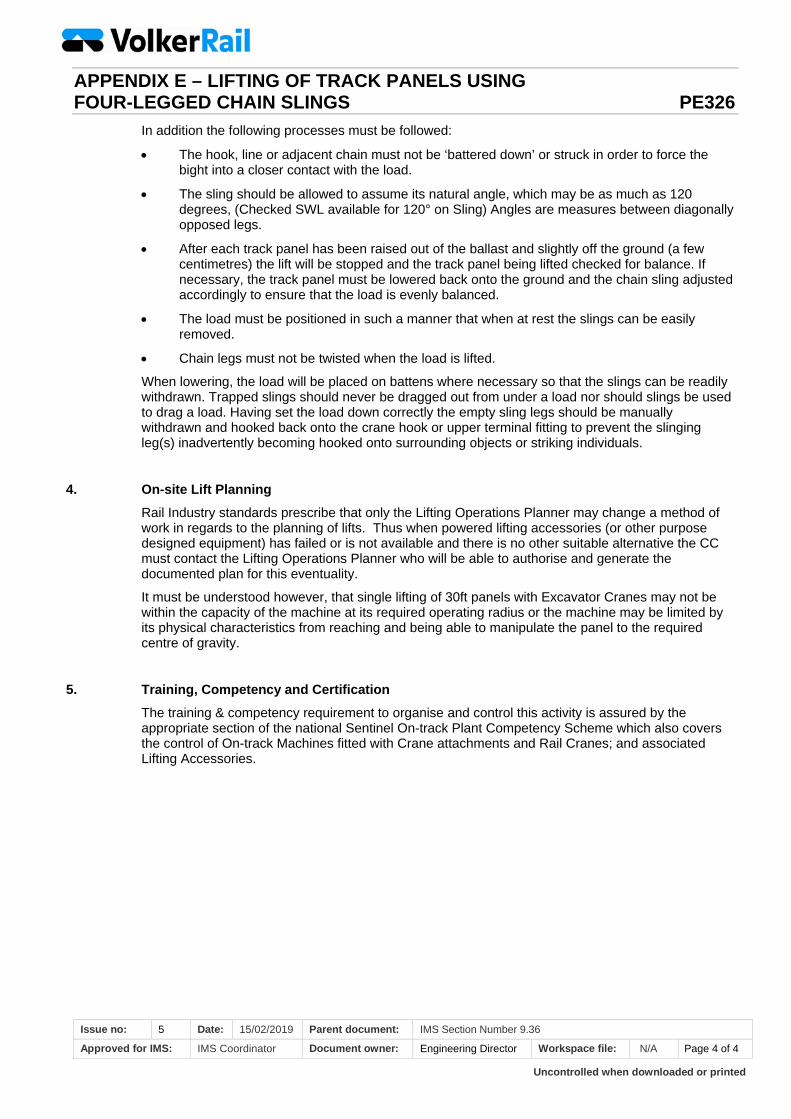
Uncontrolled when downloaded or printed
APPENDIX E – LIFTING OF TRACK PANELS USING FOUR-LEGGED CHAIN SLINGS PE326
Issue no: 5 Date: 15/02/2019 Parent document: IMS Section Number 9.36
Approved for IMS: IMS Coordinator Document owner: Engineering Director Workspace file: N/A Page 4 of 4
In addition the following processes must be followed:
The hook, line or adjacent chain must not be ‘battered down’ or struck in order to force the bight into a closer contact with the load.
The sling should be allowed to assume its natural angle, which may be as much as 120 degrees, (Checked SWL available for 120° on Sling) Angles are measures between diagonally opposed legs.
After each track panel has been raised out of the ballast and slightly off the ground (a few centimetres) the lift will be stopped and the track panel being lifted checked for balance. If necessary, the track panel must be lowered back onto the ground and the chain sling adjusted accordingly to ensure that the load is evenly balanced.
The load must be positioned in such a manner that when at rest the slings can be easily removed.
Chain legs must not be twisted when the load is lifted.
When lowering, the load will be placed on battens where necessary so that the slings can be readily withdrawn. Trapped slings should never be dragged out from under a load nor should slings be used to drag a load. Having set the load down correctly the empty sling legs should be manually withdrawn and hooked back onto the crane hook or upper terminal fitting to prevent the slinging leg(s) inadvertently becoming hooked onto surrounding objects or striking individuals.
4. On-site Lift Planning
Rail Industry standards prescribe that only the Lifting Operations Planner may change a method of work in regards to the planning of lifts. Thus when powered lifting accessories (or other purpose designed equipment) has failed or is not available and there is no other suitable alternative the CC must contact the Lifting Operations Planner who will be able to authorise and generate the documented plan for this eventuality.
It must be understood however, that single lifting of 30ft panels with Excavator Cranes may not be within the capacity of the machine at its required operating radius or the machine may be limited by its physical characteristics from reaching and being able to manipulate the panel to the required centre of gravity.
5. Training, Competency and Certification
The training & competency requirement to organise and control this activity is assured by the appropriate section of the national Sentinel On-track Plant Competency Scheme which also covers the control of On-track Machines fitted with Crane attachments and Rail Cranes; and associated Lifting Accessories.

Uncontrolled when downloaded or printed
APPENDIX F – LIFTING, MOVEMENT OR STACKING OF PLAIN RAILS & RAILS CONTAINING PREFABRICATED GLUED INSULATED JOINTS (NOT LONGER THAN 18.3M) PE326
Issue no: 5 Date: 15/02/2019 Parent document: IMS Section Number 9.36
Approved for IMS: IMS Coordinator Document owner: Engineering Director Workspace file: N/A Page 1 of 18
1. Introduction
This appendix details VolkerRail’s management arrangements for control of lifting and stacking operations involving plain and IBJ rails not exceeding 18.3m (60’) in length so that this activity can be undertaken safely and without inducing latent defects into the rail material that could lead to broken rails or other defects during the service life of the rail.
2. Scope
The arrangements shall apply when undertaking lifting and stacking of rails on all infrastructures where VolkerRail is the Main Contractor, Sub contractor or part of a Joint Venture arrangement. It specifically applies when such operations are undertaken on VolkerRail work sites within a new build railway site, an Operational Railway or in a Depot.
It sets out the safe method to be adopted for the lifting and stacking of plain rails not longer than 18.3m (60’) with a single hook crane, or a road/rail excavator used for lifting using:
An approved lifting beam
Strap lifting slings
A single point lift of a rail not exceeding six metres (20 feet) in length, only to be used for plain rails (not IBJs)
A site or depot stillage
This standard does not apply to thimbling operations using rail thimbles attached to Road / Rail excavators.
These specific instructions are issued in M&EE Code of Practice COP 0005 Handling Serviceable Rail with RRV Excavator Cranes including Thimbling. Codes of Practices are available via the IMS.
Thimbles must never be used for lifting short rails.
M&EE Code of Practice COP 0022 Pulling Rail with Road-Rail Excavator Cranes shall be used wherever there is a requirement to pull individual lengths of CWR by a rail mounted road-rail excavator crane. Alternative methods of handling rails may only be considered within green-field work sites and depots that are not connected to the Operational railway following appropriate risk assessments and subject to prior approval being obtained from the Engineering Director or Head of Track Engineering.
3. Introduction to arrangements
3.1. Minimal handling
The lifting or movement of rail can be dangerous or hazardous operation if undertaken without forethought and planning. A carelessly placed stack of rail can be a hazard to anyone working in the vicinity of the stack or attempting to remove rail from it. It is imperative that the handling of rail on site is kept to a minimum to reduce this risk.
3.2. Avoidance of damage
Damage due to impact from tools or mishandling of rail can cause ‘hard spots’ which create stress raisers and can lead to latent defects causing rail failure at any time in the future.
Incorrect handling of glued insulated joint rails can cause a severe stress on the joint itself and lead to premature failure of the insulating components, track circuit failure and significant train delays.
Incorrect stacking of the rail can lead to latent defects and twisting or other distortion of the rail rendering it unfit for use.
Uncontrolled when downloaded or printed
APPENDIX F – LIFTING, MOVEMENT OR STACKING OF PLAIN RAILS & RAILS CONTAINING PREFABRICATED GLUED INSULATED JOINTS (NOT LONGER THAN 18.3M) PE326
Issue no: 5 Date: 15/02/2019 Parent document: IMS Section Number 9.36
Approved for IMS: IMS Coordinator Document owner: Engineering Director Workspace file: N/A Page 2 of 18
3.3. Positioning of rails on site
Rails should always be offloaded as close as possible to their final required position. In order to move rail any significant distance it is generally necessary to utilise lifting and moving equipment. This will entail some method of attaching a lifting or pulling device to the rail and subsequent attachment of such a device to a mode of mechanised transportation i.e. crane, excavator etc.
The safety of site personnel is paramount and as such rail movement should only be undertaken if it cannot be avoided by good planning and then only with the minimum number of staff required in order to achieve the task.
4. Safe Method of Work
4.1. Communication of arrangements
The lifting of rail must be included within a specific task brief prior to commencement of work together with the authorised method statement/works package plan and appropriate measures to identify and communicate/control the risk causation as appropriate. No person must move or remain under the lifting device or load when the rail is suspended.
A Lift Plan shall be produced by a competent lift planner for all lifting operations.
4.2. Exclusion Zones
The Project Manager shall ensure a documented risk assessment is undertaken of the site specific details/requirements and a suitable exclusion zone chosen.
Recommended suitable values are as follows, but these still require validation and assessments (L = Length of rail).
Rail on beam or straps on RRV or Crane, exclusion zone ½L +3m.
Rail carried on forks (metal on rubber) exclusion zone L +5m.
Rail carried on forks (metal on metal – undesirable) exclusion zone L+50% or L+5m whichever is greatest
Single point lift on RRV or crane, exclusion zone L +3m.
Only personnel involved directly with the rail movement shall be allowed within twice the length of the rail being lifted from the centre of the hook; or lifting beam for short rail lengths i.e. 60ft or less; and when longer rails are being lifted or towed non-involved personnel should be totally clear of the rail movement area.
Any rail damaged during its movement must be noted and assessment made as soon as possible as to its acceptability as ‘fit for purpose’. This may involve use of rail flaw detection equipment.
4.3. Use of Lifting Beam
Only lifting beams, constructed to a design approved by the VolkerRail Plant Engineering Manager, and / or Engineering Director and with an appropriate valid test certificate may be used.
All hired-in lifting beams shall be procured through VolkerRail Plant from approved suppliers.
Approved hydraulic lifting beams that attach to road/rail excavators may be used. These are available from TME, Geismar or Philmor Rail. All hydraulic lifting beams and the machinery to which they will be attached must have complimentary engineering acceptance to work with each other.
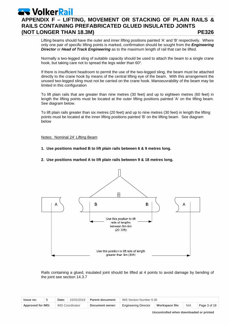
Uncontrolled when downloaded or printed
APPENDIX F – LIFTING, MOVEMENT OR STACKING OF PLAIN RAILS & RAILS CONTAINING PREFABRICATED GLUED INSULATED JOINTS (NOT LONGER THAN 18.3M) PE326
Issue no: 5 Date: 15/02/2019 Parent document: IMS Section Number 9.36
Approved for IMS: IMS Coordinator Document owner: Engineering Director Workspace file: N/A Page 3 of 18
Lifting beams should have the outer and inner lifting positions painted 'A' and 'B' respectively. Where only one pair of specific lifting points is marked, confirmation should be sought from the Engineering Director or Head of Track Engineering as to the maximum length of rail that can be lifted.
Normally a two-legged sling of suitable capacity should be used to attach the beam to a single crane hook, but taking care not to spread the legs wider than 60o.
If there is insufficient headroom to permit the use of the two-legged sling, the beam must be attached directly to the crane hook by means of the central lifting eye of the beam. With this arrangement the unused two-legged sling must not be carried on the crane hook. Manoeuvrability of the beam may be limited in this configuration
To lift plain rails that are greater than nine metres (30 feet) and up to eighteen metres (60 feet) in length the lifting points must be located at the outer lifting positions painted 'A' on the lifting beam. See diagram below.
To lift plain rails greater than six metres (20 feet) and up to nine metres (30 feet) in length the lifting points must be located at the inner lifting positions painted 'B' on the lifting beam. See diagram below
Notes: Nominal 24’ Lifting Beam
1. Use positions marked B to lift plain rails between 6 & 9 metres long.
2. Use positions marked A to lift plain rails between 9 & 18 metres long.
Rails containing a glued, insulated joint should be lifted at 4 points to avoid damage by bending of the joint see section 14.3.7
Uncontrolled when downloaded or printed
APPENDIX F – LIFTING, MOVEMENT OR STACKING OF PLAIN RAILS & RAILS CONTAINING PREFABRICATED GLUED INSULATED JOINTS (NOT LONGER THAN 18.3M) PE326
Issue no: 5 Date: 15/02/2019 Parent document: IMS Section Number 9.36
Approved for IMS: IMS Coordinator Document owner: Engineering Director Workspace file: N/A Page 4 of 18
4.4. Fasetta Beams
It has been determined that Fasetta beams may be used and these do not have a detrimental effect on plain rails, despite their comparatively short length. Fasetta beams should not be used for lifting prefabricated glued rails that are over 9144mm long.
4.5. Prior to Moving the Rail – Pre-planning Off Site
Consider the following:
The length of rail to be moved.
The rail weight.
The distance to be moved.
Whether there is a need to rotate the rail.
The type of rail – rail section, conductor rail, grooved rail, glued IBJ panel etc.
The terrain over which the rail is to be moved.
Any obstructions which may hinder movement e. g. overhead wires, over bridges, etc.
Other works within the vicinity of the rail movement.
The type of device to be attached to the rail during the movement.
The method of transportation to be adopted.
Staff certificated for the movement of rail i.e. crane controllers, etc.
Crane lifting plan as per VolkerRail Forms PE326F05 as appropriate and Machine Operational Plan as per VolkerRail Form PE326F01.
Appropriate level area and dunnage for stacking
4.6. Prior to Moving the Rail – On Site
Confirm all staff who are to undertake the task are properly certificated.
The rail position - Rails must always be moved in the head upward position. (If a rail to be lifted is not in the head up position, it must be turned by use of approved rail turning bars (see VolkerRail Standard P&E/313 Safe Turning of Rails Using Rail Turning Bars) and held by wedges or chocks (if needed) to ensure it remains upright when attaching the lifting device).
The attachment points for the lifting / moving device (to ensure an even balance) the centre of the rail and lifting points must be pre-marked on rails that are to be lifted. The ancillary equipment must be attached to within 25mm of those lifting points to ensure an even balance.
When attaching the lifting / moving device there must be no twists or kinks in any straps or chains.
Lifts must always be vertical and the rail horizontal (except for sag). Rails must not be pushed or dragged during a lift or by a lifting machine, at any time. Rails shall never be lifted at one end with the other end pivoting on the ground.
The lifting device must always be located over the centre of the length of rail to be lifted.
For single point lifting of plain rails the correct Camlok clamp must be used and the rail length must not be exceeded.
Tandem lifting of rails should be undertaken with a Camlok and chain at each end to avoid damage to Fasetta and other similar rigid beams due to the twisting effect from the differing machine movements.
Has the site been checked for obstructions and built into the lifting and operational plans?
Is the proposed method of moving the rail i.e. the crane, excavator, etc capable of undertaking the task? Are it, and its attachments, certificated to do so together and is there an authorised crane plan for the activity?
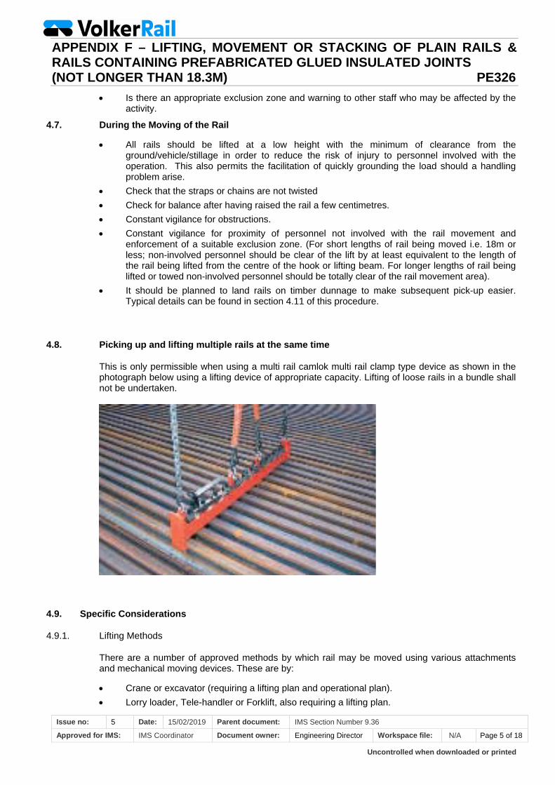
Uncontrolled when downloaded or printed
APPENDIX F – LIFTING, MOVEMENT OR STACKING OF PLAIN RAILS & RAILS CONTAINING PREFABRICATED GLUED INSULATED JOINTS (NOT LONGER THAN 18.3M) PE326
Issue no: 5 Date: 15/02/2019 Parent document: IMS Section Number 9.36
Approved for IMS: IMS Coordinator Document owner: Engineering Director Workspace file: N/A Page 5 of 18
Is there an appropriate exclusion zone and warning to other staff who may be affected by the activity.
4.7. During the Moving of the Rail
All rails should be lifted at a low height with the minimum of clearance from the ground/vehicle/stillage in order to reduce the risk of injury to personnel involved with the operation. This also permits the facilitation of quickly grounding the load should a handling problem arise.
Check that the straps or chains are not twisted
Check for balance after having raised the rail a few centimetres.
Constant vigilance for obstructions.
Constant vigilance for proximity of personnel not involved with the rail movement and enforcement of a suitable exclusion zone. (For short lengths of rail being moved i.e. 18m or less; non-involved personnel should be clear of the lift by at least equivalent to the length of the rail being lifted from the centre of the hook or lifting beam. For longer lengths of rail being lifted or towed non-involved personnel should be totally clear of the rail movement area).
It should be planned to land rails on timber dunnage to make subsequent pick-up easier. Typical details can be found in section 4.11 of this procedure.
4.8. Picking up and lifting multiple rails at the same time
This is only permissible when using a multi rail camlok multi rail clamp type device as shown in the photograph below using a lifting device of appropriate capacity. Lifting of loose rails in a bundle shall not be undertaken.
4.9. Specific Considerations
4.9.1. Lifting Methods
There are a number of approved methods by which rail may be moved using various attachments and mechanical moving devices. These are by:
Crane or excavator (requiring a lifting plan and operational plan).
Lorry loader, Tele-handler or Forklift, also requiring a lifting plan.
Uncontrolled when downloaded or printed
APPENDIX F – LIFTING, MOVEMENT OR STACKING OF PLAIN RAILS & RAILS CONTAINING PREFABRICATED GLUED INSULATED JOINTS (NOT LONGER THAN 18.3M) PE326
Issue no: 5 Date: 15/02/2019 Parent document: IMS Section Number 9.36
Approved for IMS: IMS Coordinator Document owner: Engineering Director Workspace file: N/A Page 6 of 18
Towed, but this is outside the scope of this instruction.
Using Iron Men as described in VolkerRail Internal Standard PE349
4.9.2. Crane or Excavator
Any crane, or excavator, which is to be used for lifting must carry certification to that effect and have marked upon the machine the safe working load which the machine is capable of lifting and be fitted with a safe load indicator (SLI).
Machines of this type may use a combination of methods for making a lift such as use of a lifting beam, chains, straps or single point lifts.
Rails must never be lifted using chains alone whether singly or as a bundle due to the inherent risk of metal chains sliding along metal rail and causing the rail to fall. This risk cannot be managed and this method shall not be used in any circumstances.
Rails greater in length than 20ft (6 metres) must not be lifted using a single point lift.
4.9.3. Forklift/ Telehandler (referred to as Forklift but applies to both)
Any Forklift must carry certification and have marked upon the safe working load which the machine is capable of lifting.
Forklifts may use a combination of methods for making a lift such as use of a lifting beam, chains or straps.
Where used, lifting beams shall be securely tied back to the forks so that there is no likelihood of the beam sliding off the end of the forks.
Forklifts may also lift rail on their forks but only if use rubber covers are placed on the forks to avoid slipping from metal on metal!
The lift required above ground must be sufficient to facilitate ground clearance without snagging but kept to the absolute minimum and the whole operation strictly controlled. An exclusion area around the activity shall be specified, including the travel area.
New rails longer than 6m shall never be lifted by a fixed fork forklift on site as this will cause excessive deflection/ flexing and permanent damage, leading to crippling in extreme cases.
A machine with adjustable forks may be used with the forks set to lift the rail at the 1/3 points and this may facilitate lifting longer rails. The terrain upon which they are to operate must be of good, smooth and firm construction free from potholes.
4.9.4. Lorry loaders
Lorry loaders come complete with the driver who is competent to operate and Control the lifts. A lifting plan is required if operating on VR sites and a Crane Controller if on Operational Railway Infrastructure.
Any ordering of rails to come by lorry shall interrogate the method of loading the rails and unloading at site and whether a beam is necessary to work with the lorry loader, whether there is sufficient spare capacity for this extra load etc. It is important that latent damage due to incorrect handling does not occur en route before it reaches VR Site.
Uncontrolled when downloaded or printed
APPENDIX F – LIFTING, MOVEMENT OR STACKING OF PLAIN RAILS & RAILS CONTAINING PREFABRICATED GLUED INSULATED JOINTS (NOT LONGER THAN 18.3M) PE326
Issue no: 5 Date: 15/02/2019 Parent document: IMS Section Number 9.36
Approved for IMS: IMS Coordinator Document owner: Engineering Director Workspace file: N/A Page 7 of 18
In the event of any materials being required a specific way round, this should be specified for the loading point as it will be impracticable to turn end for end using the lorry loader.
VolkerRail are responsible for ensuring the ground conditions are sufficient to support the outriggers of the lorry at the unloading position.
4.9.5. Side Loaders
Specially designed side loading machines are acceptable for use as part of the manufacturing process in a factory condition under arrangements for the Depot. Side loaders would not normally be appropriate for site usage. Should there be a requirement to use this method; The Depot Manager or Project Manager should propose the equipment and method to the Engineering Director or Head of Track Engineering for acceptance well before the work and procurement of plant.
Working in a static depot only, a side-loader Fork Lift may lift rails using narrower fixed forks than those specified in 4.9.3 only from:
the stockpile onto its flat bed
the flat bed onto and off the fabrication position
The flat bed onto a lorry
4.9.6. Lifting Equipment
There are a number of different types of lifting equipment all of which must be regularly checked, and carry certificates of validity. These shall be comparable and certified, where necessary, as compatible with the host machine. Approved specific equipment includes:
Lifting beams (Compatibility required)
Strap lifting slings
Chains
Camloks
Any equipment that does not have current valid certification must not be used, must be taken out of use immediately and quarantined.
The following tables provide details of the Camlok clamps and strap lifting slings for use with running, conductor and grooved rails.
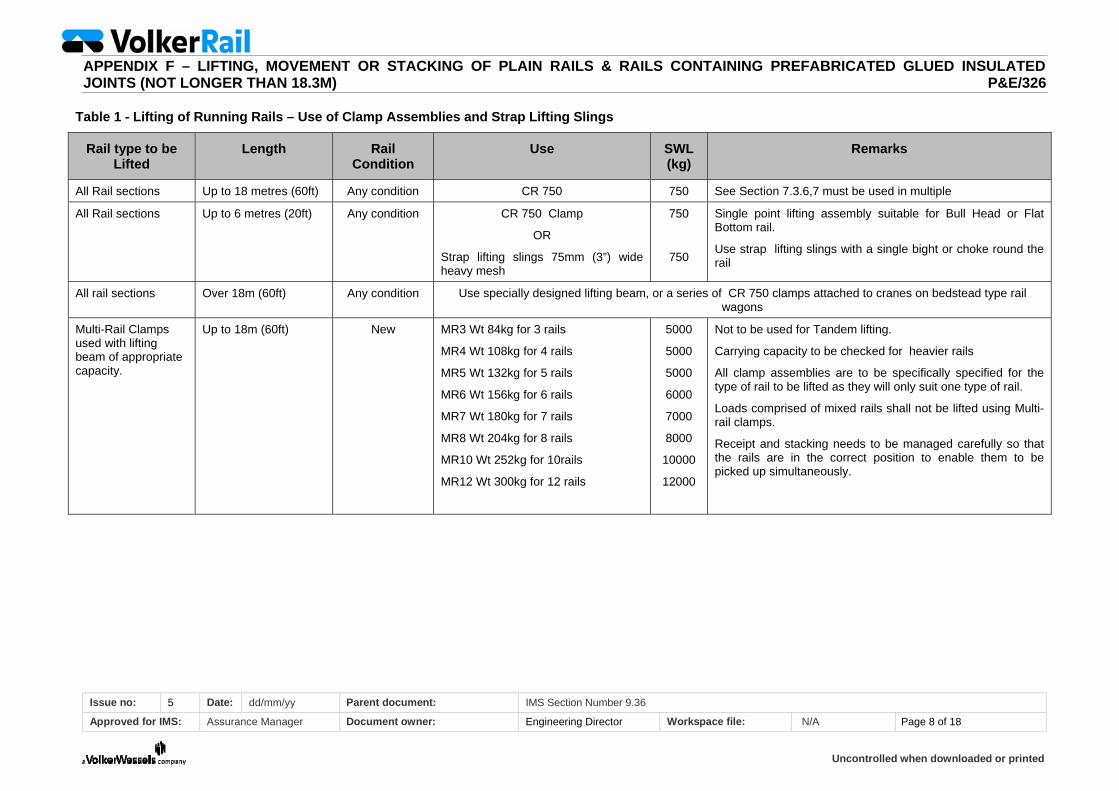
Uncontrolled when downloaded or printed
APPENDIX F – LIFTING, MOVEMENT OR STACKING OF PLAIN RAILS & RAILS CONTAINING PREFABRICATED GLUED INSULATED JOINTS (NOT LONGER THAN 18.3M) P&E/326
Issue no: 5 Date: dd/mm/yy Parent document: IMS Section Number 9.36
Approved for IMS: Assurance Manager Document owner: Engineering Director Workspace file: N/A Page 8 of 18
Table 1 - Lifting of Running Rails – Use of Clamp Assemblies and Strap Lifting Slings
Rail type to be Lifted
Length Rail Condition
Use SWL (kg)
Remarks
All Rail sections Up to 18 metres (60ft) Any condition CR 750 750 See Section 7.3.6,7 must be used in multiple
All Rail sections Up to 6 metres (20ft) Any condition CR 750 Clamp
OR
Strap lifting slings 75mm (3”) wide heavy mesh
750
750
Single point lifting assembly suitable for Bull Head or Flat Bottom rail.
Use strap lifting slings with a single bight or choke round the rail
All rail sections Over 18m (60ft) Any condition Use specially designed lifting beam, or a series of CR 750 clamps attached to cranes on bedstead type rail wagons
Multi-Rail Clamps used with lifting beam of appropriate capacity.
Up to 18m (60ft) New MR3 Wt 84kg for 3 rails
MR4 Wt 108kg for 4 rails
MR5 Wt 132kg for 5 rails
MR6 Wt 156kg for 6 rails
MR7 Wt 180kg for 7 rails
MR8 Wt 204kg for 8 rails
MR10 Wt 252kg for 10rails
MR12 Wt 300kg for 12 rails
5000
5000
5000
6000
7000
8000
10000
12000
Not to be used for Tandem lifting.
Carrying capacity to be checked for heavier rails
All clamp assemblies are to be specifically specified for the type of rail to be lifted as they will only suit one type of rail.
Loads comprised of mixed rails shall not be lifted using Multi-rail clamps.
Receipt and stacking needs to be managed carefully so that the rails are in the correct position to enable them to be picked up simultaneously.
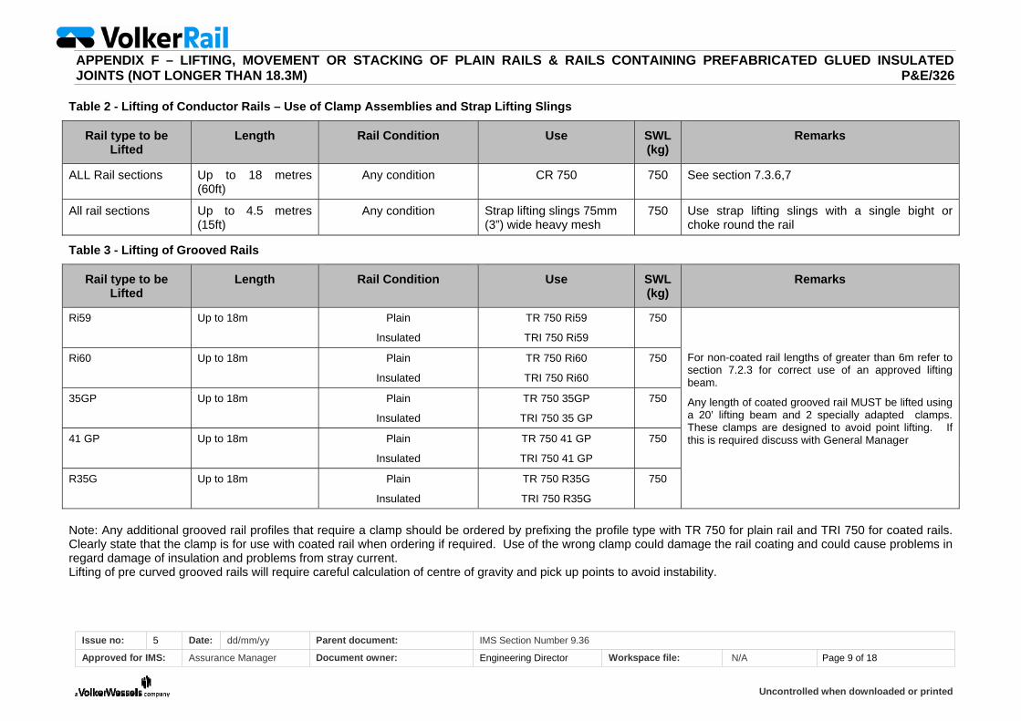
Uncontrolled when downloaded or printed
APPENDIX F – LIFTING, MOVEMENT OR STACKING OF PLAIN RAILS & RAILS CONTAINING PREFABRICATED GLUED INSULATED JOINTS (NOT LONGER THAN 18.3M) P&E/326
Issue no: 5 Date: dd/mm/yy Parent document: IMS Section Number 9.36
Approved for IMS: Assurance Manager Document owner: Engineering Director Workspace file: N/A Page 9 of 18
Table 2 - Lifting of Conductor Rails – Use of Clamp Assemblies and Strap Lifting Slings
Rail type to be Lifted
Length Rail Condition Use SWL (kg)
Remarks
ALL Rail sections Up to 18 metres (60ft)
Any condition CR 750 750 See section 7.3.6,7
All rail sections Up to 4.5 metres (15ft)
Any condition Strap lifting slings 75mm (3”) wide heavy mesh
750 Use strap lifting slings with a single bight or choke round the rail
Table 3 - Lifting of Grooved Rails
Rail type to be Lifted
Length Rail Condition Use SWL (kg)
Remarks
Ri59 Up to 18m Plain
Insulated
TR 750 Ri59
TRI 750 Ri59
750
For non-coated rail lengths of greater than 6m refer to section 7.2.3 for correct use of an approved lifting beam.
Any length of coated grooved rail MUST be lifted using a 20’ lifting beam and 2 specially adapted clamps. These clamps are designed to avoid point lifting. If this is required discuss with General Manager
Ri60 Up to 18m Plain
Insulated
TR 750 Ri60
TRI 750 Ri60
750
35GP Up to 18m Plain
Insulated
TR 750 35GP
TRI 750 35 GP
750
41 GP Up to 18m Plain
Insulated
TR 750 41 GP
TRI 750 41 GP
750
R35G Up to 18m Plain
Insulated
TR 750 R35G
TRI 750 R35G
750
Note: Any additional grooved rail profiles that require a clamp should be ordered by prefixing the profile type with TR 750 for plain rail and TRI 750 for coated rails. Clearly state that the clamp is for use with coated rail when ordering if required. Use of the wrong clamp could damage the rail coating and could cause problems in regard damage of insulation and problems from stray current. Lifting of pre curved grooved rails will require careful calculation of centre of gravity and pick up points to avoid instability.
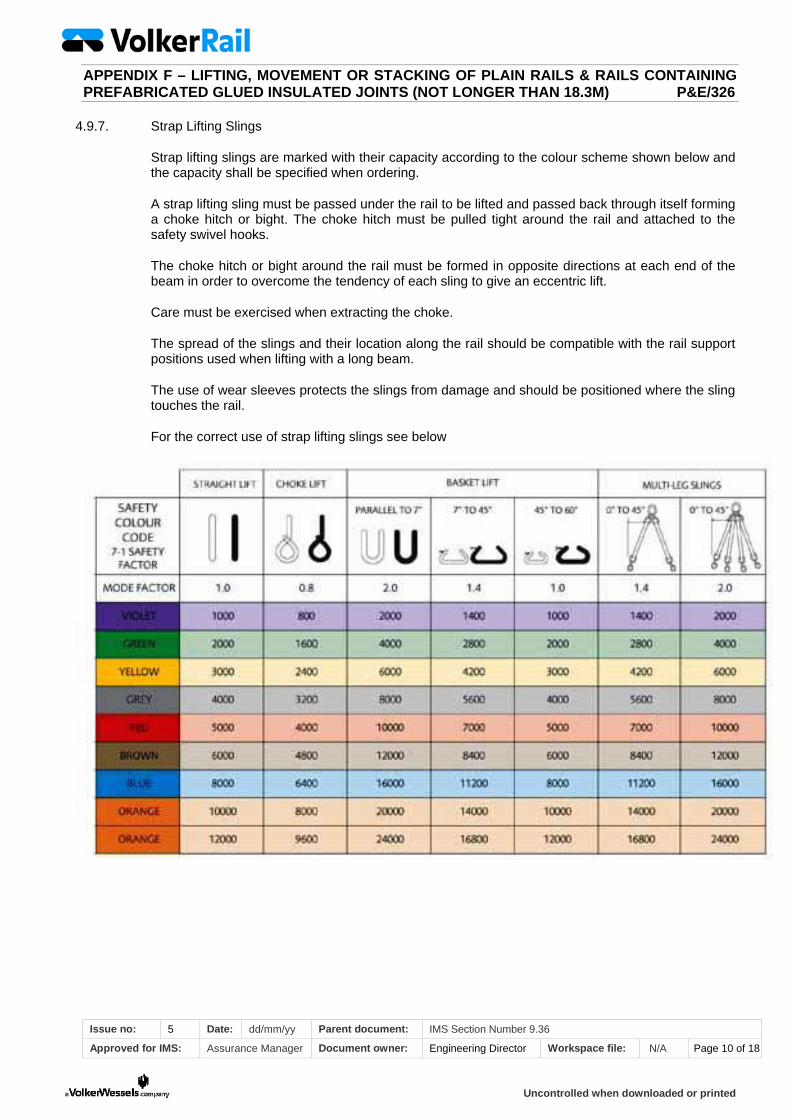
Uncontrolled when downloaded or printed
APPENDIX F – LIFTING, MOVEMENT OR STACKING OF PLAIN RAILS & RAILS CONTAINING PREFABRICATED GLUED INSULATED JOINTS (NOT LONGER THAN 18.3M) P&E/326
Issue no: 5 Date: dd/mm/yy Parent document: IMS Section Number 9.36
Approved for IMS: Assurance Manager Document owner: Engineering Director Workspace file: N/A Page 10 of 18
4.9.7. Strap Lifting Slings
Strap lifting slings are marked with their capacity according to the colour scheme shown below and the capacity shall be specified when ordering.
A strap lifting sling must be passed under the rail to be lifted and passed back through itself forming a choke hitch or bight. The choke hitch must be pulled tight around the rail and attached to the safety swivel hooks.
The choke hitch or bight around the rail must be formed in opposite directions at each end of the beam in order to overcome the tendency of each sling to give an eccentric lift.
Care must be exercised when extracting the choke.
The spread of the slings and their location along the rail should be compatible with the rail support positions used when lifting with a long beam.
The use of wear sleeves protects the slings from damage and should be positioned where the sling touches the rail.
For the correct use of strap lifting slings see below
Uncontrolled when downloaded or printed
APPENDIX F – LIFTING, MOVEMENT OR STACKING OF PLAIN RAILS & RAILS CONTAINING PREFABRICATED GLUED INSULATED JOINTS (NOT LONGER THAN 18.3M) P&E/326
Issue no: 5 Date: dd/mm/yy Parent document: IMS Section Number 9.36
Approved for IMS: Assurance Manager Document owner: Engineering Director Workspace file: N/A Page 11 of 18
4.9.8. Chains
Chains shall only be used for lifting rails in association with beams, camloks etc and never on their own.
Chains are marked with their safe working load and certification which should be specified on ordering and checked on site.
4.9.9. Camloks
Camloks carry their safe working load and are specifically designed to fit different rail sections see Tables 1 and 2
4.10. Special requirements when lifting curved rails
Curved rails are particularly difficult to handle due to their shape. Rails may be curved vertically or horizontally.
4.10.1. Vertical curvature
Rails curved in the vertical profile will usually only be found on tramways. Lifting will not cause a problem because the centre of gravity is unchanged and the normal lifting methods shall be used.
When stacking vertically curved rails, appropriate dunnage packings will need to be used so that the rails are supported to the designed curvature and also at the spacings used for all rails and shown in section 4.11.
4.10.2. Horizontal curvature
Rails curved in the horizontal profile are inherently unstable because of the offset centre of gravity. Calculation of the centre of gravity is difficult, but a diagram of curved rail lifting and an example of how this can be done is included in section 4.10.3. The rail can only be lifted in a level situation if the 2 pick up points are at the points on the rails which are identified in the calculation above or if the preferred solution of multiple pick up points are used e.g. with a long beam (but still a straight beam with a curved rail and non matching points therefore requiring adjustable strops).
Picking up of horizontally curved rails with a Fork Lift or side loader will always result in an imbalance of the rail as the rail ends outside the support zone will be heavier than the rail between the forks, therefore causing the outer edges to dip. This will create a tendency for the rail to slide in the direction of the heaviest end and vibration/ swing may cause them to move and work their way to the end of the forks or in a worst case scenario fall off the end of the forks if the Fork Lift is operating on the convex side of the rail.
Wherever possible, therefore, the process and operational requirement should always be designed so that the rails are lifted from the concave side which will cause them to move onto the forks in the event of disturbance and assuming that the forks are inclined upwards from the horizontal.
Where this is not possible and lifting has to take place on the convex side of the rail, auxiliary ratchet attachments or similar should be used to tie back the rail to the uprights of the forks for each lift.
Where a lifting beam is used in association with the forks, the process will generally require the beam to be on the end of the forks to reach the rear of the stack. The beam must be securely attached to the forks and have a restraint to prevent it sliding off the forks and not be held loose on them. The process should still be devised so that the rail can be lifted on the concave side, wherever possible, but this will not require restraint over and above that used for the lifting beam

Uncontrolled when downloaded or printed
APPENDIX F – LIFTING, MOVEMENT OR STACKING OF PLAIN RAILS & RAILS CONTAINING PREFABRICATED GLUED INSULATED JOINTS (NOT LONGER THAN 18.3M) P&E/326
Issue no: 5 Date: dd/mm/yy Parent document: IMS Section Number 9.36
Approved for IMS: Assurance Manager Document owner: Engineering Director Workspace file: N/A Page 12 of 18
4.10.3. Curved rail lifting diagram and calculation of Centre of Gravity
See next page

Uncontrolled when downloaded or printed
APPENDIX F – LIFTING, MOVEMENT OR STACKING OF PLAIN RAILS & RAILS CONTAINING PREFABRICATED GLUED INSULATED JOINTS (NOT LONGER THAN 18.3M) P&E/326
Issue no: 5 Date: dd/mm/yy Parent document: IMS Section Number 9.36
Approved for IMS: Assurance Manager Document owner: Engineering Director Workspace file: N/A Page 13 of 18
Line through centre of gravity of rail
Tangent to centre of rail, parallel to line thro’ C of G
Line through rail ends parallel to line thro’ C of G
Length of rail = L metres
Weight per metre= W per metre
Radius of rail = R metres
L3 is approx L/2
L1
L2
Chord length on radius of rail over length of rail (C)
Length of rail around curve between positions of C of G. L3
Calculation: ( W x L3) x L1/2 = {(L-L3) x W} x L2/2 L/2 x L1/2 = L/2 x L2/2 L1/2 = L2/2 So the lifting points will be close to the L/4 position and a trial lift should be undertaken to adjust this to a precise value depending on which way the rail tips when lifted
Uncontrolled when downloaded or printed
APPENDIX F – LIFTING, MOVEMENT OR STACKING OF PLAIN RAILS & RAILS CONTAINING PREFABRICATED GLUED INSULATED JOINTS (NOT LONGER THAN 18.3M) P&E/326
Issue no: 5 Date: 15/02/2019 Parent document: IMS Section Number 9.36
Approved for IMS: Assurance Manager Document owner: Engineering Director Workspace file: N/A Page 14 of 18
4.11. Staking and Stocking of Rails
4.11.1. Basic Preparation
The stability and security of a stack is determined entirely by the quality of the base preparation. The base must be level and flat, free from projections, and firm (preferably built on concrete for long term use). If an earth base is to be used it should be well drained, uniformly compacted without any soft areas and be of inert material. Base supports and hard wooden dunnage should be evenly spaced by a maximum of 3.5 metres along the rail length, with special care being taken to support near rail ends to a maximum of 1 metre. Rails forming the bottom layer should be carefully aligned and care should be taken to avoid overlapping of rail flanges. (6 dunnage battens required per layer in 18288mm stack.
4.11.2. Subsequent layers
In the assembly of a stack or stockpile of rails these essential guidelines should be followed:
Form stacks from rails of the same length
Segregate rails according to specific criteria such as drilling and/or length of the rails. Where this is not possible place the shorter rails in the upper layers
Avoid a leaning stack by placing rail ends (rails of the same length) in vertical alignment
When dunnage is used do not cross layers. Keep the rails in a uniform lengthways direction
Ensure the good vertical alignment of dunnage or spacers in the completed stack by placing them in identical positions above the base support
Wooden timber dunnage should be of a uniform and adequate thickness typically 100mm x 100mm cross section to guarantee stack stability and allow for sling removal without ‘ripping-out’.
Each successive layer of rail should be of either a constant or decreasing width but bearing in mind the order in which it is required to be used may require separate stacks
4.11.3. Guidelines for exposed storage over a long period of time
Rust generated over a long period of time could be damaging to the rail. To avoid this, the following guidelines should be followed. Please note this is strictly for rails stored over a long period of time.
Space rails at least 50mm apart (between each foot)
Space each layer of the rails 50mm – 100mm apart
Stack all rails with a gentle slope between ends to allow water run off
The stack should be aligned with the wind direction where possible to improve ventilation through the stack

Uncontrolled when downloaded or printed
APPENDIX F – LIFTING, MOVEMENT OR STACKING OF PLAIN RAILS & RAILS CONTAINING PREFABRICATED GLUED INSULATED JOINTS (NOT LONGER THAN 18.3M) P&E/326
Issue no: 5 Date: 15/02/2019 Parent document: IMS Section Number 9.36
Approved for IMS: Assurance Manager Document owner: Engineering Director Workspace file: N/A Page 15 of 18
Photographs illustrating a good stack of rails:
Uncontrolled when downloaded or printed
APPENDIX F – LIFTING, MOVEMENT OR STACKING OF PLAIN RAILS & RAILS CONTAINING PREFABRICATED GLUED INSULATED JOINTS (NOT LONGER THAN 18.3M) P&E/326
Issue no: 5 Date: 15/02/2019 Parent document: IMS Section Number 9.36
Approved for IMS: Assurance Manager Document owner: Engineering Director Workspace file: N/A Page 16 of 18
4.12. Planning
A robust plan must be produced for the lifts or movements of rails. The Project Manager shall ensure that only competent persons prepare and check plans, control the activities on site and act as Controllers/Slingers etc. All the plant and ancillary equipment shall be specified in detail to the supplier so that it is compatible and can all work together safely.
4.13. Effects on the Rail Caused By Incorrect Lifting
4.13.1. Crippled Rail
This is rail that has received a permanent ‘set’, bend or kink. The set may be in the horizontal or vertical plane or a combination of both. Crippling may also be torsional caused by twisting or a combination of forces on the asymmetrical cross section.
For a rail to be crippled it must have been stressed beyond its elastic limit and its fatigue life will be severely reduced. Once a rail has been crippled it will NEVER be possible to restore its alignment and if used it will affect the surrounding rail, other track components including the ballast structure. Crippled rails may have to be discarded as scrap.
4.13.2. Identification of Crippled Rail
Crippled rails will often be clearly identifiable once installed and fastened down, (but may be difficult to assess whilst out of track). Sighting along the rail may reveal vertical and horizontal bends or kinks. Torsional crippling will be less visible but may be discernible as a misalignment of the head; there may also be visible distortion of the bottom flange after installation. Flange distortion may also be present in other types of crippling or damage.
Slightly crippled rails may be hard to see when first installed and may only become visible after the passage of traffic when a discontinuity in the wear pattern will be apparent. As with other abnormalities in wear pattern the cause should be investigated and as part of this process rail crippling must be investigated and the decision taken by a Competent P Way Engineer as to whether the rail should be removed or not.
4.13.3. Damaged Rail
Damage to rail caused by mechanical or manual handling will usually take the form of dents, incisions or gouges in the rail surface. In severe cases pieces of steel may actually be broken out. Such damage will normally be easy to see when fresh but may, if rust is allowed to form, be extremely difficult to detect after a few hours.
Most handling will only cause slight marking and abrasions or grip marks caused by the serrated jaws of handling or tensor equipment. It may be only the removal of rust or scale. Such marks are undesirable but may be acceptable in the head and the web areas if limited to no more than 0.1mm deep. They should not consist of sharp edged or ‘V’ shaped grooves particularly if transverse to the rail. All damage to the foot of the rail, including the underside, should be avoided. The insertion of bars or other handling equipment in ANY holes in the rail is dangerous in itself and will cause severe damage and shortening of the rail’s life.
Any visible damage should be removed by soft grinding by a competent Track Welder.
4.13.4. Principal Causes of Crippling and Surface Damage
Rails may be crippled from a number of causes including:
Use of inappropriate equipment to attach lifting tackle.
Not using lifting beams of an appropriate length.
Lack of care when lifting or moving rail horizontally i.e. taking excessively large ‘bites’.
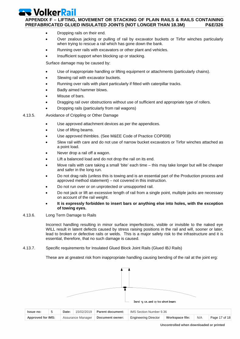
Uncontrolled when downloaded or printed
APPENDIX F – LIFTING, MOVEMENT OR STACKING OF PLAIN RAILS & RAILS CONTAINING PREFABRICATED GLUED INSULATED JOINTS (NOT LONGER THAN 18.3M) P&E/326
Issue no: 5 Date: 15/02/2019 Parent document: IMS Section Number 9.36
Approved for IMS: Assurance Manager Document owner: Engineering Director Workspace file: N/A Page 17 of 18
Dropping rails on their end.
Over zealous jacking or pulling of rail by excavator buckets or Tirfor winches particularly when trying to rescue a rail which has gone down the bank.
Running over rails with excavators or other plant and vehicles.
Insufficient support when blocking up or stacking.
Surface damage may be caused by:
Use of inappropriate handling or lifting equipment or attachments (particularly chains).
Slewing rail with excavator buckets.
Running over rails with plant particularly if fitted with caterpillar tracks.
Badly aimed hammer blows.
Misuse of bars.
Dragging rail over obstructions without use of sufficient and appropriate type of rollers.
Dropping rails (particularly from rail wagons)
4.13.5. Avoidance of Crippling or Other Damage
Use approved attachment devices as per the appendices.
Use of lifting beams.
Use approved thimbles. (See M&EE Code of Practice COP008)
Slew rail with care and do not use of narrow bucket excavators or Tirfor winches attached as a point load.
Never drop a rail off a wagon.
Lift a balanced load and do not drop the rail on its end.
Move rails with care taking a small ‘bite’ each time – this may take longer but will be cheaper and safer in the long run.
Do not drag rails (unless this is towing and is an essential part of the Production process and approved method statement) – not covered in this instruction.
Do not run over or on unprotected or unsupported rail.
Do not jack or lift an excessive length of rail from a single point, multiple jacks are necessary on account of the rail weight.
It is expressly forbidden to insert bars or anything else into holes, with the exception of towing eyes.
4.13.6. Long Term Damage to Rails
Incorrect handling resulting in minor surface imperfections, visible or invisible to the naked eye WILL result in latent defects caused by stress raising positions in the rail and will, sooner or later, lead to broken or defective rails or welds. This is a major safety risk to the infrastructure and it is essential, therefore, that no such damage is caused.
4.13.7. Specific requirements for Insulated Glued Block Joint Rails (Glued IBJ Rails)
These are at greatest risk from inappropriate handling causing bending of the rail at the joint erg:

Uncontrolled when downloaded or printed
APPENDIX F – LIFTING, MOVEMENT OR STACKING OF PLAIN RAILS & RAILS CONTAINING PREFABRICATED GLUED INSULATED JOINTS (NOT LONGER THAN 18.3M) P&E/326
Issue no: 5 Date: 15/02/2019 Parent document: IMS Section Number 9.36
Approved for IMS: Assurance Manager Document owner: Engineering Director Workspace file: N/A Page 18 of 18
Careless handling may cause irreparable damage and greatly shorten the life of the rail/joint or even cause it to fail on the initial signalling testing. It is preferable to use long beams when lifting IBJs.
Lifts should preferably be undertaken by lifting at 4 points, 2 points at each side of the joint.
All lifts of IBJs must be undertaken as detailed below:
1. Four point lifting should be used wherever possible, by using all 4 pick up points on a 24’ (7.3 metre) lifting beam for all rails 6+ metres long.
2. Tandem lifting of IBJs using two independent positions of support will permanently damage the IBJ and is prohibited. If tandem lifting of IBJs is required, it shall be via a 4 point lifting beam that is directly attached to the two machines.
APPENDIX G – CARRYING OUT PILING OPERATIONS PE326
Issue no: 1 Date: 12/06/2019 Parent document: IMS Section Number 9.36, PE326
Approved for IMS: IMS Coordinator Document owner: Engineering Director Workspace file: N/A Page 1 of 6
1. PURPOSE The purpose of this appendix is to:
Bring OTP Piling operations within the scope of VolkerRail (VR) procedure PE326;
Detail the specific arrangements necessary to manage the safe and efficient organisation and control when carrying out OTP piling operations by VR within a specific worksite;
Mandate compliance with the requirements of:
o NR/L2/RMVP/0200 Network Rail (NwR) Plant Manual;
o Provision and Use of Work Equipment Regulations (PUWER) 1998
o Lifting Operations and Lifting Equipment Regulations (LOLER)1998
Incorporate the recommendations of M&EE Networking Group Code of Practice for On-Track Piling COP0034 into PE326.
2. SCOPE This procedure applies to all piling activities, including the organisation, planning and control of piling operations using OTP covering the piling equipment groupings within the scope of this documentation including:
Piling driver vibratory
Piling hammer
Piling torque head
Auger driver
3. REFERENCES (INPUTS) / RELATED DOCUMENTS M&EE Networking Group Code of Practice for Operator Competency Standards for On Track
Plant COP0001
M&EE Networking Group Code of Practice for Loading of OTP COP0017
M&EE Networking Group Code of Practice for On Track Piling COP0034
M&EE Networking Group Code of Practice for Planning for the Use of Mobile Operated Plant COP 0002
M&EE Networking Group Code of Practice for Any Line Open (ALO) Working COP0032
NR/L2/RMVP/0200 Network Rail Plant Manual
NR/L2/TRK/2102 Design and Construction of Track
Federation of piling Specialists (FPS) Working Platform Certificate (FPS/WPC/4d)
CIV508 - Working in and Around Excavations
CIV510 - Management of Temporary Works
SAF30 - Risk Assessment
ENG02 - Production of Work Package Plans, Method Statements
PAN 01
4. PLANNING
For OTP piling operations carried out by VR piling department all work shall be planned as stated in VR procedure PE326 - Vehicular Plant and Crane Operations. In addition to this;
Pile design shall be provided either internally or by a third party geotechnical/pile design contractor
The correct type/size of OTP and suitable piling attachments for types of pile & ground conditions to be installed shall be selected by the Lift Planner.
A site visit shall be carried out by the Lift Planner before work commences and wherever possible during daylight hours to identify:
o The track geometry within the work area, location and suitability of the RRAP, delivery access, pile storage areas
o Any hazards on site that could affect piling operations so control measures can be put into the lift plans
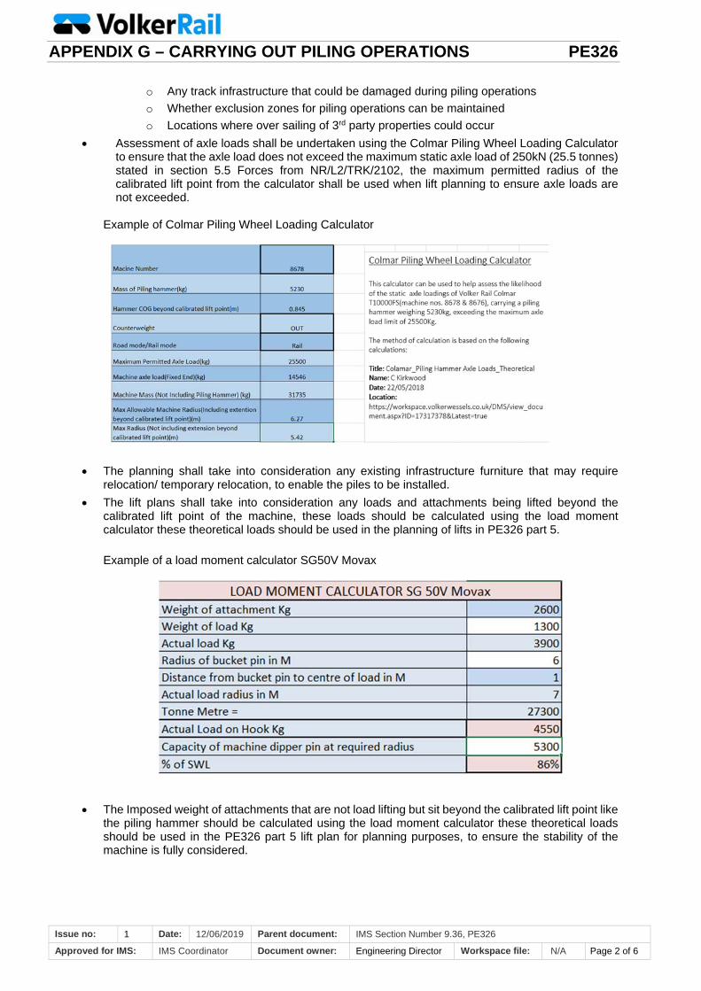
APPENDIX G – CARRYING OUT PILING OPERATIONS PE326
Issue no: 1 Date: 12/06/2019 Parent document: IMS Section Number 9.36, PE326
Approved for IMS: IMS Coordinator Document owner: Engineering Director Workspace file: N/A Page 2 of 6
o Any track infrastructure that could be damaged during piling operations
o Whether exclusion zones for piling operations can be maintained
o Locations where over sailing of 3rd party properties could occur
Assessment of axle loads shall be undertaken using the Colmar Piling Wheel Loading Calculator to ensure that the axle load does not exceed the maximum static axle load of 250kN (25.5 tonnes) stated in section 5.5 Forces from NR/L2/TRK/2102, the maximum permitted radius of the calibrated lift point from the calculator shall be used when lift planning to ensure axle loads are not exceeded.
Example of Colmar Piling Wheel Loading Calculator
The planning shall take into consideration any existing infrastructure furniture that may require relocation/ temporary relocation, to enable the piles to be installed.
The lift plans shall take into consideration any loads and attachments being lifted beyond the calibrated lift point of the machine, these loads should be calculated using the load moment calculator these theoretical loads should be used in the planning of lifts in PE326 part 5.
Example of a load moment calculator SG50V Movax
The Imposed weight of attachments that are not load lifting but sit beyond the calibrated lift point like the piling hammer should be calculated using the load moment calculator these theoretical loads should be used in the PE326 part 5 lift plan for planning purposes, to ensure the stability of the machine is fully considered.
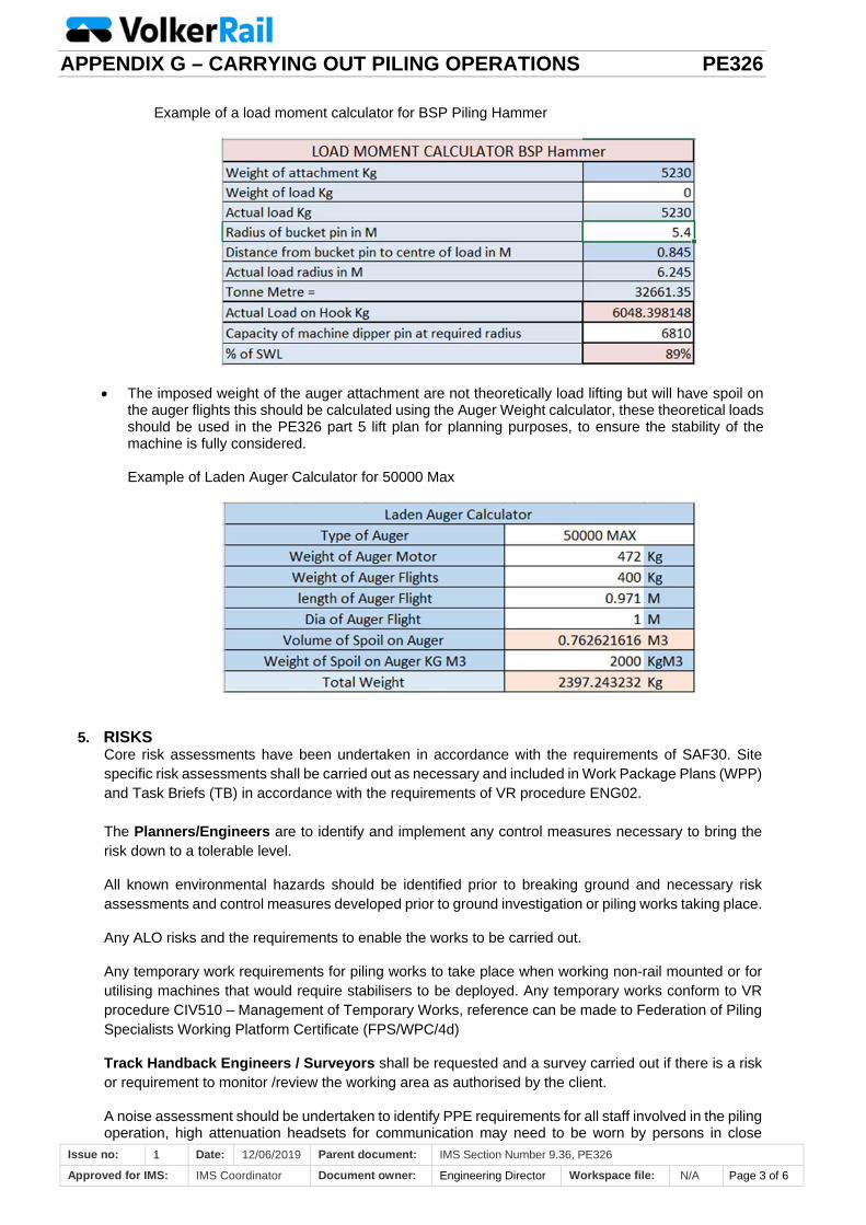
APPENDIX G – CARRYING OUT PILING OPERATIONS PE326
Issue no: 1 Date: 12/06/2019 Parent document: IMS Section Number 9.36, PE326
Approved for IMS: IMS Coordinator Document owner: Engineering Director Workspace file: N/A Page 3 of 6
Example of a load moment calculator for BSP Piling Hammer
The imposed weight of the auger attachment are not theoretically load lifting but will have spoil on the auger flights this should be calculated using the Auger Weight calculator, these theoretical loads should be used in the PE326 part 5 lift plan for planning purposes, to ensure the stability of the machine is fully considered.
Example of Laden Auger Calculator for 50000 Max
5. RISKS
Core risk assessments have been undertaken in accordance with the requirements of SAF30. Site specific risk assessments shall be carried out as necessary and included in Work Package Plans (WPP) and Task Briefs (TB) in accordance with the requirements of VR procedure ENG02. The Planners/Engineers are to identify and implement any control measures necessary to bring the risk down to a tolerable level.
All known environmental hazards should be identified prior to breaking ground and necessary risk assessments and control measures developed prior to ground investigation or piling works taking place.
Any ALO risks and the requirements to enable the works to be carried out.
Any temporary work requirements for piling works to take place when working non-rail mounted or for utilising machines that would require stabilisers to be deployed. Any temporary works conform to VR procedure CIV510 – Management of Temporary Works, reference can be made to Federation of Piling Specialists Working Platform Certificate (FPS/WPC/4d)
Track Handback Engineers / Surveyors shall be requested and a survey carried out if there is a risk or requirement to monitor /review the working area as authorised by the client.
A noise assessment should be undertaken to identify PPE requirements for all staff involved in the piling operation, high attenuation headsets for communication may need to be worn by persons in close

APPENDIX G – CARRYING OUT PILING OPERATIONS PE326
Issue no: 1 Date: 12/06/2019 Parent document: IMS Section Number 9.36, PE326
Approved for IMS: IMS Coordinator Document owner: Engineering Director Workspace file: N/A Page 4 of 6
proximity to the operation. Section 61 prior consent application for noise should be in place where applicable and where practical the use of acoustic curtains or barriers are to be used to reduce the noise levels.
6. PILING METHODOLOGY a) Each location prior to piling should1 be trial dug to the required/approved dimensions for the type
of piles to be installed, following VR procedure CIV508 - Working in and Around Excavations, this is to include photographic evidence of the trial holes.
b) A permit to dig (CIV508F01 or equivalent) will be issued confirming that each location is clear of services and OK to pile, this will be issued prior to any piling works taking place, by the Principal Contractor.
c) All piling operations should be planned under PE326 and parts 1-5 taking into account any loads lifted past calibrated lift point as stated in section 4.
d) A minimum exclusion zone shall be set up and maintained to include the collapse radius where applicable, the minimum exclusion zone for those not involved with the piling operation will be the length of the pile + 50% from pile been installed.
e) All piles placed on RRV trailers for transportation will be loaded and secured for transportation to prevent movement. M&EE Networking Group Code of Practice for Loading of OTP COP0017 refers.
f) Check the control grid coordinates with the engineer prior to piling taking place to ensure correct orientation.
g) As the pile section is driven into the ground, the orientation and level should be checked throughout. During these checks all piling operations should temporarily cease, when any deviations are identified the pile section should be manoeuvred in line with the offsets before the pile is embedded too deep to adjust or manipulate.
h) If there is a variance in the ground conditions highlighted in the design or sudden voiding then works should cease immediately and instructions sought from the site supervisor, CRE or designer.
i) The number of piles taken to site shall be counted and cross referenced to the actual piles installed to ensure unused piles are not left on site and foul of the infrastructure.
7. PILING DRIVER VIBRATORY a) Piling Supervisor and Crane Controller to ensure the pile is kept vertical during installation. b) Exclusion zones as in section 6 for area to be maintained at all times. c) When using EMV piling hammers pile securing chains and clutches are to be examined at all times
when in use for damage. d) When using the side grip piling hammers the Crane Controllers are to ensure the Operator has
got the pile securely held in the jaws. e) As the pile is driven into the ground, the Piling Supervisor will request the Crane Controller to
inform the RRV Operator to temporarily cease piling operations to allow the Supervisor/Engineer to ensure the piles are in the correct alignment and orientation. During this time the Operator will use the dead-man lever to ensure no movement of the RRV, any alterations to pile orientation will be done before the pile is driven beyond a depth that will allow manipulation.
f) Driving is to be monitored to ensure that if pile is refusing excessive blows do not cause the pile to be damaged.
g) The piling unit temperature is to be monitored to ensure the gearbox does not overheat, following manufacturer’s instructions, using a laser thermometer.
8. PILING HAMMER a) Piling Supervisor and Crane Controller to ensure the pile is kept vertical during installation. b) Consideration is to be given to the exclusion zones at all times. c) Checks are to be made during operations to ensure the security of the piling cap to the hammer. d) For sheet piling operations the correct piling cap is attached to the piles, before the hammer is used.
1 On Network Rail managed infrastructure it is Mandatory to dig a trial hole PAN 01 refers
APPENDIX G – CARRYING OUT PILING OPERATIONS PE326
Issue no: 1 Date: 12/06/2019 Parent document: IMS Section Number 9.36, PE326
Approved for IMS: IMS Coordinator Document owner: Engineering Director Workspace file: N/A Page 5 of 6
e) Driving is to be monitored to ensure that if pile is refusing excessive blows do not cause the pile top to distort.
f) As the pile is driven into the ground, the Piling Supervisor will request the Crane Controller to inform the RRV Operator to temporarily cease piling operations to allow the supervisor/engineer to ensure the piles are in the correct alignment, orientation and depth. During this time the Operator will use the dead man lever to ensure no movement of the RRV, any alterations to pile orientation will be done before the pile is driven too deep.
9. PILING TORQUE HEAD (Screw Piles) This is used to drive helical piles into the ground to provide foundations for structures using very high rotational forces at slow speed with a measurable torque reading. a) Piling Supervisor and Crane Controller to ensure the pile is kept vertical/correct alignment during
installation. b) Consideration is to be taken with exclusion zones to ensure that staff do not become entangled with
the screw pile, when required to join units together processes are to be implemented to ensure that the power is isolated to the torque motor before the joining process commences.
c) Torque motor readings will be monitored by the Piling Supervisor/Piling Installer every 500mm, if different follow the torque head motor manufacturers instructions or the recommendations from the pile manufacturer.
d) Torque motor settings have to be monitored to ensure the pile is achieving the correct resistance into the ground.
e) As the pile is screwed into the ground, the Piling Supervisor will request the Crane Controller to inform the RRV Operator to temporarily cease piling operations, to allow the supervisor/engineer to ensure the piles are in the correct alignment and depth. During this time the Operator will use the dead man lever to ensure no movement of the RRV, any alterations to pile will be done before the pile is driven too deep
10. AUGER DRIVER a) Piling Supervisor and Crane Controller to ensure the pile is kept vertical during installation. b) Consideration is to be taken with exclusion zones to ensure that staff do not become entangled
with Auger. This is when staff are required to clear debris from the auger flights or when joining units together if required, Crane Controller to inform the RRV Operator to temporarily cease operations to allow the staff to enter the exclusion zone, during this time the Operator will use the dead man lever to ensure no movement of the RRV.
c) Consideration is to be given to ensure the auger is not pulled into the ground too much causing machine instability, Operator to monitor RCI.
d) Consideration is to be given to ensure the auger is not pulled out of the ground with too much loose material on causing machine instability, Operator to monitor RCI
e) Ensure the auger is not overloaded to cause back stability issues.
11. COMPETENCE During the planning stage requests for staff should ensure that Operators & Crane Controllers hold the relevant competence for the attachments being used sentinel attachment groups for Operators are; 03- Auger Driver 21- Piling Hammer 36- Piling Driver –Vibratory 37- Piling Torque Head
For Crane Controllers the sentinel attachment group is
Crane Controller group 2 Civils
APPENDIX G – CARRYING OUT PILING OPERATIONS PE326
Issue no: 1 Date: 12/06/2019 Parent document: IMS Section Number 9.36, PE326
Approved for IMS: IMS Coordinator Document owner: Engineering Director Workspace file: N/A Page 6 of 6
This group covers Auger Driver Piling Hammer Piling Driver –Vibratory Piling Torque Head Cone Penetration Test Unit