Embed Size (px)
Citation preview

INTERNATIONAL AMMUNITION TECHNICAL GUIDELINE
IATG 01.80
Second edition 2015-02-01 Amendment 1 2016-11-03
Formulae for ammunition management
IATG 01.80:2015[E]
© UN ODA 2015

IATG 01.80:2015[E] 2nd Edition (2015-02-01) Amendment 1 (2016-11-03)
i
Warning
The International Ammunition Technical Guidelines (IATG) are subject to regular review and revision. This document is current with effect from the date shown on the cover page. To verify its status, users should consult the UN SaferGuard IATG project through the United Nations Office for Disarmament Affairs (UNODA) website at: www.un.org/disarmament/un-saferguard.
Copyright notice
This document is an International Ammunition Technical Guideline and is copyright protected by the United Nations. Neither this document, nor any extract from it, may be reproduced, stored or transmitted in any form, or by any means, for any other purpose without prior written permission from UNODA, acting on behalf of the United Nations.
This document is not to be sold.
United Nations Office for Disarmament Affairs (UNODA) United Nations Headquarters, New York, NY 10017, USA E-mail: [email protected] Tel: +1 917 367 2904 Fax: +1 917 367 1757
UN 2015 – All rights reserved

IATG 01.80:2015[E] 2nd Edition (2015-02-01) Amendment 1 (2016-11-03)
ii
Contents
Contents .................................................................................................................................................. ii
Foreword ................................................................................................................................................ iv
Introduction ............................................................................................................................................. v
Formulae for ammunition management .................................................................................................. 1
1 Scope ................................................................................................................................................ 1
2 Normative references ....................................................................................................................... 1
3 Terms and definitions ....................................................................................................................... 1
4 Background ....................................................................................................................................... 2
5 Cube root scaling law ....................................................................................................................... 2
6 Air blast ............................................................................................................................................. 3
6.1 Rankine-Hugoniot (shock front parameters) ................................................................................................. 3
6.1.1. Shock front velocity ...................................................................................................................................................... 3
6.1.2. Particle velocity ............................................................................................................................................................ 3
6.1.3. Air density behind the shock front ................................................................................................................................ 3
6.1.4. Dynamic pressure ........................................................................................................................................................ 4
6.1.5. Reflected pressure ....................................................................................................................................................... 4
6.2 Blast over pressure and impulse ................................................................................................................... 4
6.2.1. Incident Pressure ......................................................................................................................................................... 5
6.2.2. Incident Impulse ........................................................................................................................................................... 5
6.2.3. Reflected Pressure ...................................................................................................................................................... 6
6.2.4. Reflected Impulse ........................................................................................................................................................ 6
6.3 Scaling law .................................................................................................................................................... 7
6.4 Reflection coefficient ..................................................................................................................................... 7
6.5 Impulse ......................................................................................................................................................... 7
6.5.1. General impulse ........................................................................................................................................................... 7
6.5.2. Scaled impulse ............................................................................................................................................................ 8
7 Explosive parameters ....................................................................................................................... 8
7.1 Detonation pressure ...................................................................................................................................... 8
7.2 TNT equivalence ........................................................................................................................................... 8
8 Ballistics ............................................................................................................................................ 9
8.1 Fragmentation velocity .................................................................................................................................. 9
8.2 Simple fragment range estimation .............................................................................................................. 10
9 Simple range safety distances ........................................................................................................ 10
9.1 Basic equations ........................................................................................................................................... 10
9.2 Basic equations (alternative) ....................................................................................................................... 11
9.3 Vertical danger areas .................................................................................................................................. 11
9.4 Simple noise prediction ............................................................................................................................... 11
10 Effects on structures ..................................................................................................................... 12
10.1 Air blast ..................................................................................................................................................... 12
10.2 Fragmentation ........................................................................................................................................... 13

IATG 01.80:2015[E] 2nd Edition (2015-02-01) Amendment 1 (2016-11-03)
iii
10.3 Ground shock ............................................................................................................................................ 13
11 Effects on people .......................................................................................................................... 14
11.1 Individual risk ............................................................................................................................................ 14
11.2 Primary blast injury levels ......................................................................................................................... 14
11.3 Secondary blast injury levels ..................................................................................................................... 15
12 Underground storage .................................................................................................................... 15
Annex A (normative) References .......................................................................................................... 17
Annex B (informative) References ........................................................................................................ 18
Amendment record ............................................................................................................................... 19

IATG 01.80:2015[E] 2nd Edition (2015-02-01) Amendment 1 (2016-11-03)
iv
Foreword
Ageing, unstable and excess ammunition stockpiles pose the dual hazards of illicit proliferation and accidental explosion, which have caused destabilization and humanitarian disaster in all regions of the world.
Crucial for adequate stockpile management is the identification of surpluses – that is, the portion of weapons and ammunition that does not constitute an operational need. When surpluses are not recognized, the entirety of the stockpile may continue to be seen as of operational value. Although not used, weapons and ammunition surpluses thus continue to fill warehouses and can thus pose a significant risk to safety and security. Defective stockpile management has been assessed as the norm rather than the exception in many countries. Often it is not only surplus stocks that should be the focus of attention, but the lack of appropriate policy for stockpile management. Governments remain unaware of surpluses; their national stockpiles remain a risk to public safety; and diversion from warehouses feed into crime and armed violence.
In 2011, the United Nations developed the International Ammunition Technical Guidelines (IATG) to ensure that the United Nations as a whole consistently delivers high-quality advice and support in ammunition management. Many stakeholders, including international organizations, non-governmental entities and national authorities, use these guidelines.
The IATG, along with other conventional ammunition issues, are managed through the United Nations SaferGuard programme.
Taking into account the diversity in capacity of States, three levels of ascending comprehensiveness are offered in the IATG, referred to as “risk-reduction process levels” (RRPLs). These are indicated within each IATG as either LEVEL 1 (basic), LEVEL 2 (intermediate) or LEVEL 3 (advanced). The aim of implementing partners should be to maintain stockpile management processes at RRPL 1 as a minimum. This will often reduce risk significantly. Ongoing and gradual improvements could then be made to the stockpile management infrastructure and processes as staff development improves and further resources become available. These additional actions would equate to RRPLs 2 and 3. The RRPLs are determined by calculating a weighted score of questions about a particular ammunition stockpile. A checklist is available at: https://www.un.org/disarmament/un-saferguard/risk-reduction-process-levels/. The IATG are reviewed on a regular basis to reflect developing ammunition stockpile management norms and practices, and to incorporate changes due to changing international regulations and requirements. The IATG are also available in multiple languages.
The latest version of each guideline, together with practical IATG implementation support tools, can be found at https://www.un.org/disarmament/un-saferguard/.

IATG 01.80:2015[E] 2nd Edition (2015-02-01) Amendment 1 (2016-11-03)
v
Introduction
The nature of ammunition and explosives with their potential for unplanned, violent reaction makes it necessary to develop recommendations and guidelines for safe conventional ammunition management stockpile management. This requires, by necessity, a risk-based approach
1, which
should be based on sound explosive engineering and science.
Risk management decisions based on more complete knowledge can be made if the likelihood of an explosives accident can be taken into account as well as the consequences. This requires knowledge of the range of scientifically accepted formulae that can be used to support decision-making and risk management during conventional ammunition stockpile management.
This IATG summarise the scientific formulae that are either useful or essential to safe, effective and efficient stockpile management. Their detailed use is explained in the other topic-specific IATG in the remainder of the guidelines or in the accompanying IATG software.
1 IATG 02.10 Introduction to Risk Management Principles and Processes contains further information on risk-based
approaches to conventional ammunition stockpile management.

IATG 01.80:2015[E] 2nd Edition (2015-02-01) Amendment 1 (2016-11-03)
1
Formulae for ammunition management
1 Scope
This IATG introduces and summarises scientifically proven and sound formulae that may be used to support the decision-making and risk management processes essential for the safe and effective stockpile management of conventional ammunition.
2 Guidance on their appropriate use is either
contained within this IATG, the complementary IATG software or in other more specific technical IATG. They are summarised here for ease of reference in their use later.
2 Normative references
The following referenced documents are indispensable for the application of this document. For dated references, only the edition cited applies. For undated references, the latest edition of the referenced document (including any amendments) applies.
A list of normative references is given in Annex A. Normative references are important documents to which reference is made in this guide and which form part of the provisions of this guide.
A further list of informative references is given at Annex B in the form of a bibliography, which lists additional documents that contain other useful information on formulae for the stockpile management of conventional ammunition.
3 Terms and definitions
For the purposes of this guide the following terms and definitions, as well as the more comprehensive list given in IATG 01.40:2015(E) Terms, definitions and abbreviations, shall apply.
The term ‘brisance’ refers to the shattering effect or power of an explosion or explosive.
The term ‘hazard’ refers to a potential source of harm.
The term ‘quantity distance’ refers to the designated safe distance between a potential explosion site and an exposed site.
The term ‘risk’ refers to a combination of the probability of occurrence of harm and the severity of that harm.
The term ‘risk management’ refers to the complete risk-based decision-making process.
In all modules of the International Ammunition Technical Guidelines, the words 'shall', 'should', 'may' and 'can' are used to express provisions in accordance with their usage in ISO standards.
a) 'shall' indicates a requirement: It is used to indicate requirements strictly to be followed in order to conform to the document and from which no deviation is permitted.
b) 'should' indicates a recommendation: It is used to indicate that among several possibilities one is recommended as particularly suitable, without mentioning or excluding others, or that a certain course of action is preferred but not necessarily required, or that (in the negative form, 'should not') a certain possibility or course of action is deprecated but not prohibited.
c) 'may' indicates permission: It is used to indicate a course of action permissible within the limits of the document.
2 The detailed use of the formulae is explained in the other topic specific IATG in the remainder of the guidelines.

IATG 01.80:2015[E] 2nd Edition (2015-02-01) Amendment 1 (2016-11-03)
2
d) ‘can’ indicates possibility and capability: It is used for statements of possibility and capability, whether material, physical or casual.
4 Background
Ammunition and explosives, by their very nature, present an inherent risk during storage and, if not managed correctly, a latent hazard to local communities in their vicinity. Undesirable explosive events regularly occur in ammunition storage areas globally, yet much of the resultant negative impact on local communities would have been preventable if effective risk management systems had been developed and implemented.
The use of proven and sound explosive science and engineering is therefore essential in supporting the risk management processes necessary to achieve safe and efficient conventional ammunition stockpile management.
This IATG contains formulae that should be used to support risk management processes within conventional ammunition stockpile management and summarises their potential use. More detailed information on the use of each formula is contained within the topic specific IATG in the remainder of the guidelines.
5 Cube root scaling law
Many States use rules based upon the explosives, their quantity, and the distance from the explosive to where people are at risk. These rules are known as Quantity-Distance (Q-D) criteria, and are based on the approach derived from the Hopkinson-Cranz Scaling Law
3 4, which is further
amended by a range of coefficients. It is the basis of much of the work on the estimation of appropriate quantity and separation distances.
NOTE 1 It is not always possible to provide the separation distances called for by Q-D, which are worst case, and an alternative risk analysis system of quantitative risk assessment (QRA) may be used. (See IATG 02.20 Quantity and separation distances for detailed information).
(R1/R2) = (W1/W2)1/3
R = Z.W1/3
R = Range (m)
Z = Constant of Proportionality (dependent on acceptable blast overpressure)
W = Explosive Weight (kg)
Table 1: Hopkinson-Cranz Scaling Law
Examples of the constant ‘Z’ used in explosive storage safety5 are shown in Table 2:
Z Purpose Remarks
8.0 Used to predict separation distances between ammunition process buildings (APB) within an explosive storage area (ESA).
Additionally minimum safe distances further apply if R is below a certain level, which differs for each ‘Z’ function.
14.8 Used to predict separation distances between an explosive storehouse (ESH) and a public traffic route with civilian access.
22.2 Used to predict separation distances between an explosive storehouse (ESH) and a building inhabited by civilians.
3 Hopkinson B, UK Ordnance Board Minutes 13565, 1915.
4 Cranz C, Lehrbuch der Ballistik, Springer-Verlag, Berlin, 1916.
5 These are the default ‘Z’ settings in the IATG Software, although the software does allow the user to input alternative ‘Z’
values.

IATG 01.80:2015[E] 2nd Edition (2015-02-01) Amendment 1 (2016-11-03)
3
Z Purpose Remarks
44.4 Used to predict separation distances between an explosive storehouse (ESH) and a vulnerable building inhabited by civilians (e.g. a school).
Table 2: Examples of Constant ‘Z’
Further details on the practical use of this formula are contained within IATG 02.20 Quantity and separation distances.
6 Air blast
The characteristic parameters of a blast wave with a sudden pressure discontinuity at the shock front are as follows:
a) over-pressure;
b) dynamic pressure;
c) reflected pressure;
d) density;
e) shock front velocity; and
f) particle velocity.
These parameters can be derived using the Rankine-Hugoniot equations.6
6.1 Rankine-Hugoniot (shock front parameters)7
6.1.1. Shock front velocity
Vsf = c . (1 + (6Ps/7P0))1/2
Vsf = Shock Front Velocity (m/s)
c = Speed of Sound (m/s)
Ps = Peak Side-On Pressure (kPa)
P0 = Ambient Pressure (kPa)
Table 3: Shock front velocity
6.1.2. Particle velocity
Vp = (5Ps/7P0). (c/(1 + (6 Ps . 7P0))1/2
)
Vp = Particle Velocity (m/s)
Ps = Peak Side-On Pressure (kPa)
P0 = Ambient Pressure (kPa)
c = Speed of Sound (m/s)
Table 4: Particle velocity
6.1.3. Air density behind the shock front
Dsf = (7 + (6 Ps /7P0)/( 7 + Ps/7P0)) . Dair
Dsf = Air Density behind Shock Front (kg/m3)
Ps = Peak Side-On Pressure (kPa)
P0 = Ambient Pressure (kPa)
Dair = Air Density
6 Rankine W J H. The Dynamics of Explosion and its Use. Elsevier. Amsterdam. 1979.
7 The Rankine-Hugoniot equations are only applicable under the condition that the particle velocity ahead of the shock front
is zero and that the air behaves as an ideal gas (with a specific heat ratio of 1.4)

IATG 01.80:2015[E] 2nd Edition (2015-02-01) Amendment 1 (2016-11-03)
4
Table 5: Air density behind the shock front
6.1.4. Dynamic pressure
The dynamic pressure during blast loading of a structure is a function of the pressure over time, as opposed to quasi-static blast loading at a given moment of time:
Pd = 5Ps2 + 2(Ps + 7P0)
Pd = Peak Dynamic Pressure (kPa)
Ps = Peak Side-On Pressure (kPa)
P0 = Ambient Pressure (kPa)
Table 6: Dynamic pressure
6.1.5. Reflected pressure8
Pr = 2Ps . ((7P0 + 4Ps)/(7P0 = Ps)) Pr = Peak Reflected Pressure (kPa)
P0 = Ambient Pressure (kPa)
Ps = Peak Side-On Pressure (kPa)
Table 7: Reflected pressure
Further details on the practical use of these formulae are contained within IATG 02.20 Quantity and separation distances or the Explosion Consequence Analysis concept in IATG 02.10 Introduction to risk management processes and the accompanying IATG software.
6.2 Blast over pressure and impulse
Equations to estimate blast over-pressure at range have been developed by Charles Kingery and Gerald Bulmash. These equations are widely accepted as engineering predictions for determining free-field pressures and loads on structures and form the basis of the US Conventional Weapons Effects Programme (CONWEP) software. Their report
9 contains a compilation of data from
explosive tests using charge weights from less than 1kg to over 400,000kg. The authors used curve-fitting techniques to represent the data with high-order polynomial equations, which are included in the accompanying software to the IATG for ease of application.
The equations are summarised in Tables 8 – 13 for information, where functions to represent the air blast parameters versus distance in metres for a 1kg TNT spherical free-air burst and hemi-spherical surface burst are shown for: 1) Incident Pressure; 2) Incident Impulse; 3) Reflected Pressure; and 4) Reflected Impulse.
The numerical values for the constants ‘C’ and ‘K’ are those for a 1kg TNT equivalent charge. Predictions for other explosives will require that the TNT equivalence be first estimated (Clause 7.2).
Y = C0 + C1U + C2U + C3U ............CnU
Y = Common Logarithm of the Air Blast Parameter (metric) (Pressure or Impulse)
C0,1 ,2 etc = Constant
U = K0 + K1T
K0, 1 etc = Constant
T = Common Logarithm of the Distance (m)
Table 8: Kingery and Bulmash general polynomial form
8 Normally reflected pressure.
9 Charles N Kingery and Gerald Bulmash. Airblast Parameters from TNT Spherical Air Burst and Hemispherical Surface
Burst, US Technical Report ARBRL-TR-02555. Ballistics Research Laboratory, Aberdeen Proving Ground, Maryland, USA. April 1984.

IATG 01.80:2015[E] 2nd Edition (2015-02-01) Amendment 1 (2016-11-03)
5
6.2.1. Incident Pressure
These equations have a range of applicability from 0.05 – 40m.
U = -0.214362789151 + 1.35034249993T Then substitute U into
Y = 2.611368669 - 1.69012801396U + 0.00804973591951U2 + 0.336743114941U3 - 0.00516226351334U4 - 0.0809228619858U5 -
0.00478507266747U6 + 0.00793030472242U7 + 0.0007684469735UR
U = K0 + K1T
T = Common Logarithm of the Distance (m)
Y = Common Logarithm of the Air Blast Parameter (metric) (Pressure or Impulse)
Table 9: Kingery and Bulmash polynomial for Incident Pressure (Spherical Free Air)
U = -0.214362789151 + 1.35034249993T Then substitute U into
Y = 2.78076916577 - 1.6958988741U + 0.154159376846U2 + 0.514060730593U3 - 0.0988534365274U4 - 0.293912623038U5 - 0.0268112345019U6 + 0.109097496421U7 + 0.00162846756311UR
U = K0 + K1T
T = Common Logarithm of the Distance (m)
Y = Common Logarithm of the Air Blast Parameter (metric) (Pressure or Impulse)
Table 9A: Kingery and Bulmash polynomial for Incident Pressure (Hemi-Spherical Surface)
6.2.2. Incident Impulse
The equation at Table 10 is only applicable for the near field range of 0.0531m, in other words immediately next to the explosive charge.
U = 2.34723921354 + 3.24299066475T
Then substitute U into
Y = 2.38830516757 - 0.443749377691U + 0.168825414684U2 + 0.0348138030308U3 -
0.010435192824U4
U = K0 + K1T
T = Common Logarithm of the Distance (m)
Y = Common Logarithm of the Air Blast Parameter (metric) (Pressure or Impulse)
Table 10: Kingery and Bulmash polynomial for Incident Impulse (very near field) (Spherical Free Air)
The equation at Table 10A is only applicable for scaled distances between 0.0674 and 0.955.
U = 2.06761908721 + 3.0760329666T Then substitute U into
Y = 2.52455620925 - 0.502992763686U + 0.171335645235U2 + 0.0450176963051U3 -
0.0118964626402U4
U = K0 + K1T
T = Common Logarithm of the Distance (m)
Y = Common Logarithm of the Air Blast Parameter (metric) (Pressure or Impulse)
Table 10A: Kingery and Bulmash polynomial for Incident Impulse (very near field) (Hemi-Spherical Surface)
The equations at Table 11 are applicable for ranges as the blast wave moves away from the explosive charge (at a scaled distance of 0.955 to 40).

IATG 01.80:2015[E] 2nd Edition (2015-02-01) Amendment 1 (2016-11-03)
6
U = -1.75305660315 + 0.30629231803T Then substitute U into
Y = 1.55197227115 - 0.40463292088U - 0.0142721946082U2 + 0.00912366316617U3 - 0.0006750681404U4 - 0.0080086371901U5 -
0.00314819515931U6 + 0.00152044783382U7
U = K0 + K1T
T = Common Logarithm of the Distance (m)
Y = Common Logarithm of the Air Blast Parameter (metric) (Pressure or Impulse)
Table 11: Kingery and Bulmash polynomial for Incident Impulse (Spherical Free Air)
U = -1.94708846747 + 2.40697745406T
Then substitute U into
Y = 1.67281645863 - 0.384519026965U - 0.0260816706301U2 + 0.00595798753822U3 - 0.014544526107U4 - 0.00663289334734U5 - 0.00284189327204U6 + 0.0013644816277U7
U = K0 + K1T
T = Common Logarithm of the Distance (m)
Y = Common Logarithm of the Air Blast Parameter (metric) (Pressure or Impulse)
Table 11A: Kingery and Bulmash polynomial for Incident Impulse (Hemi-Spherical Surface)
6.2.3. Reflected Pressure
This equation has a range of applicability from 0.05 – 40m.
U = -0.214362789151 + 1.35034249993T
Then substitute U into
Y = 3.22958031387 - 2.21400538997U + 0.035119031446U2 + 0.657599992109U3 + 0.0141818951887U4 - 0.243076636231U5 -
0.0158699803158U6 + 0.0492741184234U7 + 0.00227639644004U8 - 0.00397126276058U9
U = K0 + K1T
T = Common Logarithm of the Distance (m)
Y = Common Logarithm of the Air Blast Parameter (metric) (Pressure or Impulse)
Table 12: Kingery and Bulmash polynomial for Reflected Pressure (Spherical Free Air)
U = -0.240657322658 + 1.36637719229T Then substitute U into
Y = 3.40283217581 - 2.21030870597U + 0.218536586295U2 + 0.895319589372U3 + 0.24989009775U4 - 0.569249436807U5 - 0.11791682383U6 + 0.224131161411U7 + 0.0245620259375U8 - 0.455116002694U9
U = K0 + K1T
T = Common Logarithm of the Distance (m)
Y = Common Logarithm of the Air Blast Parameter (metric) (Pressure or Impulse)
Table 12A: Kingery and Bulmash polynomial for Reflected Pressure (Hemi-Spherical Surface)
6.2.4. Reflected Impulse
These equations have a range of applicability from 0.05 – 40m.
U = 0.204004553231 + 1.37882996018T
Then substitute U into
Y = 2.55875660396 - 0.903118886091U + 0.101771877942U2 - 0.0242139751146U3
U = K0 + K1T
T = Common Logarithm of the Distance (m)
Y = Common Logarithm of the Air Blast Parameter (metric) (Pressure or Impulse)
Table 13: Kingery and Bulmash polynomial for Reflected Impulse (Spherical Free Air)

IATG 01.80:2015[E] 2nd Edition (2015-02-01) Amendment 1 (2016-11-03)
7
U = -0.246208804814 + 1.33422049854T Then substitute U into
Y = 2.70588058103 - 0.949516092853U + 0.112136118689U2 - 0.0250659183287U3
U = K0 + K1T
T = Common Logarithm of the Distance (m)
Y = Common Logarithm of the Air Blast Parameter (metric) (Pressure or Impulse)
Table 13A: Kingery and Bulmash polynomial for Reflected Impulse (Hemi-Spherical Surface)
Further details on the practical use of these formulae are contained within the Explosion Consequence Analysis concept in IATG 02.10 Introduction to risk management processes and the accompanying IATG software.
6.3 Scaling law
In the case of blast waves from explosions produced at altitude, where ambient conditions can be very different from those at sea level, the most commonly used scaling law is that due to Sachs.
10
The application of the Sachs scaling law leads to the formulation of altitude scaling factors.
Scaled Distance at Altitude ‘z’
Sdz = (P0/Pz)1/3
Scaled Pressure at Altitude ‘z’
Spz = (Pz/P0)
Scaled Impulse at Altitude ‘z’
Siz = (Pz/P0)2/3
. (T0/Tz)1/2
Scaled Impulse at Altitude ‘z’
St = (P0/Pz)1/3
. (T0/Tz)1/2
Sdz = Scaled Distance at Altitude ‘z’ (m)
P0 = Ambient Pressure (kPa) (101.33kPa)
Pz = Pressure at Altitude ‘z’ (kPa)
Spz = Scaled Pressure at Altitude ‘z’ (kPa)
Siz = Scaled Impulse at Altitude ‘z’ (kg.m/s)
T0 = Ambient Temperature (K) (288.160K)
Tz = Temperature at Altitude ‘z’ (K)
St = Scaled Times at Altitude ‘z’ (s)
Table 14: Sachs scaling factors
6.4 Reflection coefficient
The Reflection Coefficient is used during explosion consequence analysis (ECA) to compare Peak Reflected Pressure against Peak Side-On Pressure:
Cr = Pr / Ps
Cr = Reflection Coefficient
Pr = Peak Reflected Pressure (kPa)
Ps = Peak Side-On Pressure (kPa)
Table 15: Reflection Coefficient
6.5 Impulse
6.5.1. General impulse
The decisive parameter for the damage caused by air blast is the positive overpressure impulse. It should be determined by integration of the positive over-pressure phase, (i.e. defined by the total area below the pressure-time curve).
10 Sachs R G. The dependence of Blast on Ambient Pressure and Temperature. Technical Report 466. Ballistics Research
Laboratory, Aberdeen Proving Ground, Maryland, USA. May 1944.

IATG 01.80:2015[E] 2nd Edition (2015-02-01) Amendment 1 (2016-11-03)
8
Is = ʃ Ps . t. dt Is = Side-On Impulse (kg.m/s)
Ps = Peak Side-On Pressure (kPa)
t = Time (s)
Table 16: General Impulse
6.5.2. Scaled impulse
The scaled impulse is often used to predict the effects of blast on humans:
Isi = Is / P01/2
. m1/3
Isi = Scaled Impulse (kg.m/s)
Is = Side-On Impulse (kg.m/s)
P0 = Ambient Pressure (kPa)
M = Mass of Individual (kg)
Table 17: Scaled Impulse on Individuals
7 Explosive parameters
7.1 Detonation pressure
The Detonation Pressure of an explosive provides an indicator of its ability to do work and determines whether it is a high brisance or low brisance explosive. It can be approximated as shown in Table 18:
Pdet = 2.5 . Vd . (D/0.0000001) Pdet = Detonation Pressure (GPa)
Vd = Velocity of Detonation of Explosive (m/s)
D = Density (g/cm3)
Table 18: Detonation Pressure
7.2 TNT equivalence
The majority of air blast and impulse equations predict for TNT, and it is therefore desirable to convert the explosive mass into equivalent TNT charge mass.
MTNTe = (Ed
exp/Ed
TNT) . Mexp
MTNTe = TNT Equivalent Mass (kg)
Edexp = Specific Detonation Energy of Explosive (J/kg)
EdTNT = Specific Detonation Energy of TNT (J/kg)
Mexp = Mass of Explosive (kg)
Table 19: TNT Equivalence
Table 20 contains pre-calculated TNT equivalence factors for a range of high explosives. These are accurate enough for design purposes.
Explosive TNT Equivalent Mass Pressure Range
(MPa) Peak Pressure Impulse
Amatol 0.99 0.98
Composition B 1.11 0.98 0.035 - 0.350
Composition C3 1.08 1.01 0.035 - 0.350
Composition C4 1.37 1.19 0.070 - 0.700
HMX 1.02 1.03 Estimate

IATG 01.80:2015[E] 2nd Edition (2015-02-01) Amendment 1 (2016-11-03)
9
Explosive TNT Equivalent Mass Pressure Range
(MPa) Peak Pressure Impulse
Octol 75/25 1.06 1.06 Estimate
PETN 1.27 1.11 0.035 - 0.700
RDX 1.14 1.09 Estimate
RDX / TNT 60/40 (Cyclotol) 1.14 1.09 0.035 - 0.350
Tetryl 1.07 1.05 0.021 - 0.140
TNT 1.00 1.00 Standard
Tritonal 1.07 0.96 0.035 - 0.700
Table 20: TNT Equivalence
8 Ballistics
8.1 Fragmentation velocity
The Gurney Equations11
are a range of formulae used in explosives engineering to predict how fast an explosive will accelerate a surrounding layer of metal or other material when the explosive detonates. This determines how fast fragments are released on detonation of an item of ammunition. This initial fragment velocity can then be used with other ballistic equations to predict either danger areas or fragment penetration.
Cylindrical Charge Equation12
(V/√2E) = ((M/Cexp) + ½))-1/2
Spherical Charge Equation13
(V/√2E) = ((M/Cexp) + 3/5))-1/2
V = Initial Fragment Velocity (m/s)
√2E = Gurney Constant for a given explosive (m/s)
M = Mass of Fragment (kg)14
Cexp = Explosive Charge Mass (kg)
Table 21: Gurney Equations
15
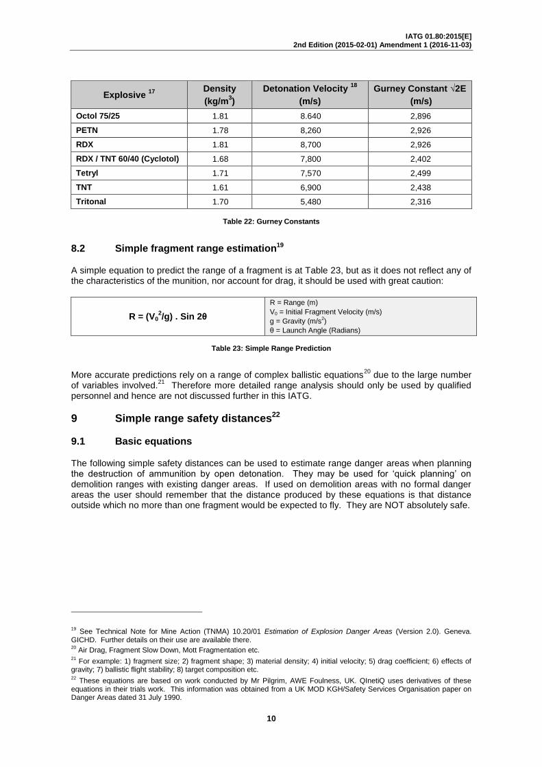
The Gurney Constant √2E is usually very close to 1/3 of the Detonation Velocity of the explosive. Table 22 contains the Gurney Constants for a range of high explosives:
16
Explosive 17
Density
(kg/m3)
Detonation Velocity 18
(m/s)
Gurney Constant √2E
(m/s)
Composition B 1.61 7,620 2,774
Composition C4 1.71 8,200 2,530
HMX 1.91 9,100 2,972
11 Gurney, R. W. The Initial Velocities of Fragments from Bombs, Shells, and Grenades, BRL-405. Ballistic Research
Laboratory, Aberdeen, Maryland. USA. 1943. 12
First order approximation for most high explosive artillery shells, mortar bombs and missile warheads. 13
Use for military grenades and some cluster bomblets. 14
For an artillery shell this is usually the base for which an estimate of mass is made from the total body mass. 15
There are other Gurney equations for symmetrical, asymmetrical, open faced and infinitely tamped sandwiches. These are beyond the scope of this IATG and have hence been excluded. 16
Densities and detonation velocities are approximate as explosive mixtures vary. 17
Details on a wide range of explosives can be found in the App “eXdata”. 18
The detonation velocity will vary dependent on the methodology used to measure it. This column includes examples.
IATG 01.80:2015[E] 2nd Edition (2015-02-01) Amendment 1 (2016-11-03)
10
Explosive 17
Density
(kg/m3)
Detonation Velocity 18
(m/s)
Gurney Constant √2E
(m/s)
Octol 75/25 1.81 8.640 2,896
PETN 1.78 8,260 2,926
RDX 1.81 8,700 2,926
RDX / TNT 60/40 (Cyclotol) 1.68 7,800 2,402
Tetryl 1.71 7,570 2,499
TNT 1.61 6,900 2,438
Tritonal 1.70 5,480 2,316
Table 22: Gurney Constants
8.2 Simple fragment range estimation19
A simple equation to predict the range of a fragment is at Table 23, but as it does not reflect any of the characteristics of the munition, nor account for drag, it should be used with great caution:
R = (V02/g) . Sin 2θ
R = Range (m)
V0 = Initial Fragment Velocity (m/s)
g = Gravity (m/s2)
θ = Launch Angle (Radians)
Table 23: Simple Range Prediction
More accurate predictions rely on a range of complex ballistic equations20
due to the large number of variables involved.
21 Therefore more detailed range analysis should only be used by qualified
personnel and hence are not discussed further in this IATG.
9 Simple range safety distances22
9.1 Basic equations
The following simple safety distances can be used to estimate range danger areas when planning the destruction of ammunition by open detonation. They may be used for ‘quick planning’ on demolition ranges with existing danger areas. If used on demolition areas with no formal danger areas the user should remember that the distance produced by these equations is that distance outside which no more than one fragment would be expected to fly. They are NOT absolutely safe.
19 See Technical Note for Mine Action (TNMA) 10.20/01 Estimation of Explosion Danger Areas (Version 2.0). Geneva.
GICHD. Further details on their use are available there. 20
Air Drag, Fragment Slow Down, Mott Fragmentation etc. 21
For example: 1) fragment size; 2) fragment shape; 3) material density; 4) initial velocity; 5) drag coefficient; 6) effects of gravity; 7) ballistic flight stability; 8) target composition etc. 22
These equations are based on work conducted by Mr Pilgrim, AWE Foulness, UK. QInetiQ uses derivatives of these equations in their trials work. This information was obtained from a UK MOD KGH/Safety Services Organisation paper on Danger Areas dated 31 July 1990.

IATG 01.80:2015[E] 2nd Edition (2015-02-01) Amendment 1 (2016-11-03)
11
For fragmenting munitions when public access is possible to the demolition range area.
D = 634(AUW)1/6
For fragmenting munitions when public access is denied to the demolition range area.
D = 444(AUW)1/6
For bare exposed explosive only.
D = 130(AUW)1/3
D = Distance (m)
AUW = All Up Weight of Ammunition or Bare Explosives (kg)
Table 24: Simple Range Safety Distances
9.2 Basic equations (alternative)
The Australian Defence Science and Technology Organisation (DSTO) conducted research in March 1997 into multi-item demolition of ammunition and explosives. They concluded that fragmentation explosion danger areas for multi-item demolitions can be reduced to that of the largest Net Explosive Quantity single munition in the demolition provided. Results from the equation in Table 25 compare favourably with those for the public access denied equation in Table 24:
a) the ordnance is arranged in a linear array and NOT a stack;
b) the ordnance is detonated simultaneously; and
c) the items are GREATER than one charge diameter apart.
D = 370(AUW)1/5
D = Distance (m)
AUW = All Up Weight of Ammunition or Bare Explosives (kg)
Table 25: Simple Range Safety Distances (Alternative)
9.3 Vertical danger areas
The equations to estimate the vertical danger areas necessary to warn air traffic of demolitions taking place on the ground differ slightly from Clauses 9.1 and 9.2 as no ballistic parabola needs to be taken into account.
For single ammunition item only.
D = 314(AUW)1/3
For multi-item fragmenting munitions.
D = 470(AUW)1/5
D = Distance (m)
AUW = All Up Weight of Ammunition or Bare Explosives (kg)
Table 26: Vertical danger Areas
9.4 Simple noise prediction
The following equation23
can be used to predict the distance at which 140dB24
of sound could be expected to be achieved:
23 Source: QinetiQ Shoeburyness, UK. 1999.
24 The EU maximum permissible noise level for a single event.

IATG 01.80:2015[E] 2nd Edition (2015-02-01) Amendment 1 (2016-11-03)
12
D = 215 (Mexp)1/3 D = Distance (m)
Mexp = Mass of Explosive (kg)
Table 27: Simple Noise Prediction
10 Effects on structures
The prediction of weapons effects on structures is a complex undertaking due to the large number of variables involved
25 and the impact that these variables have on structural response to blast
loading.
10.1 Air blast
Rough estimates for structural damage due to air blast may be obtained from empirically derived models based on an analysis of accidents, trials and war damage data. This analysis correlates the structural damage with the distance from the explosion and the charge mass involved.
The most extensive data is available for brick-built structures due to studies undertaken in World War 2. Explosion induced damage categories for brick built housing have been developed
26 which
may be used in explosion consequence analysis to illustrate the potential severity of the effects of an undesirable explosion:
Category Definition Remarks
A Houses completely demolished.
B Houses so badly damaged they are beyond repair and require demolition.
50% - 75% of external brickwork destroyed.
Remaining walls have gaping cracks that are un-repairable.
CB Houses rendered uninhabitable but can be repaired with extensive work.
Partial or total collapse of roof structure.
Partial demolition of walls up to 25% of the whole.
Severe damage to load bearing partitions necessitating demolition and replacement.
CA Houses rendered uninhabitable but can be repaired reasonably quickly.
Does not exceed minor structural damage.
Partitions and joinery wrenched from fittings.
D Houses requiring repairs to remedy serious inconvenience but remain habitable.
Damage to ceilings and tiling.
Minor fragmentation effects on walls and glazing.
Table 28: Brick Built Housing Damage Categories
The data analysis used to produce Table 28 led to an empirically derived formula to estimate damage range.
Rx = (Kx . Mexp1/3
) / ( 1 + (3175/Mexp)2)1/6
Rx = Range for Damage Level ‘x’ (m)
Kx = Constant for Damage Level ‘x’ (See Table 29)
Mexp = Mass of Explosive (kg)
Table 29: Damage Range to Buildings Estimation
25 For example: 1) structure type; 2) structure material strength, elasticity and ductility; 3) structural response to blast
loading; 4) diffraction loading effects; 5) drag loading effects; 6) building orientation to blast loading; 7) local topography etc. 26
Through the work of: 1) Scilly N F and High W G. The blast effect of explosions. Loss prevention and safety promotion 5. 1986; and 2) Jarrett D E. Derivation of the British Explosives Safety Distances. Annals New York Academy of Sciences, 152, Article 1. 1968.
IATG 01.80:2015[E] 2nd Edition (2015-02-01) Amendment 1 (2016-11-03)
13
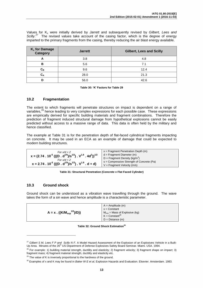
Values for Kx were initially derived by Jarrett and subsequently revised by Gilbert, Lees and Scilly.
27 The revised values take account of the casing factor, which is the degree of energy
imparted to the primary fragments from the casing, thereby reducing the air blast energy available.
Kx for Damage Category
Jarrett Gilbert, Lees and Scilly
A 3.8 4.8
B 5.6 7.1
CB 9.6 12.4
CA 28.0 21.3
D 56.0 42.6
Table 30: ‘K’ Factors for Table 29
10.2 Fragmentation
The extent to which fragments will penetrate structures on impact is dependent on a range of variables,
28 hence leading to very complex expressions for each possible case. These expressions
are empirically derived for specific building materials and fragment combinations. Therefore the prediction of fragment induced structural damage from hypothetical explosions cannot be easily predicted without access to a massive range of data. This data is often held by the military and hence classified.
The example at Table 31 is for the penetration depth of flat-faced cylindrical fragments impacting on concrete. It may be used in an ECA as an example of damage that could be expected to modern building structures.
For x/d < 2
x = (2.74 . 10-5
(((D . d1/5
)/s1/2
) . V1.8
. 4d2))
1/2
For x/d > 2
x = 2.74 . 10-5
(((D . d1/5
)/s1/2
) . V1.8
. d + d)
x = Fragment Penetration Depth (m)
d = Fragment Diameter (m)
D = Fragment Density (kg/m3)
s = Compressive Strength of Concrete (Pa)
V = Fragment Velocity (m/s)
Table 31: Structural Penetration (Concrete v Flat Faced Cylinder)
10.3 Ground shock
Ground shock can be understood as a vibration wave travelling through the ground. The wave takes the form of a sin wave and hence amplitude is a characteristic parameter.
A = x . ((K/Mexp1/2
)/D))
A = Amplitude (m)
x = Constant
Mexp = Mass of Explosive (kg)
K = Constant29
D = Distance (m)
Table 32: Ground Shock Estimation
30
27 Gilbert S M, Lees F P and Scilly N F. A Model Hazard Assessment of the Explosion of an Explosives Vehicle in a Built-
Up Area. Minutes of the 26th US Department of Defense Explosives Safety Board Seminar. Miami. USA. 1994.
28 For example: 1) building material strength, ductility and elasticity; 2) fragment velocity; 3) fragment shape on impact; 3)
fragment mass; 4) fragment material strength, ductility and elasticity etc. 29
The value of K is inversely proportional to the hardness of the ground. 30
Examples of x and K may be found in Baker W E et al, Explosion Hazards and Evaluation. Elsevier. Amsterdam. 1983.

IATG 01.80:2015[E] 2nd Edition (2015-02-01) Amendment 1 (2016-11-03)
14
Buildings of solid construction are unlikely to be damaged by amplitudes of less than 2 x 10⁻⁴
m whilst those of a more vulnerable construction should remain undamaged if the amplitude remains 8 x 10
-5m.
A damage index31
has been developed which relates the mass of explosives and the type of ground:
ɸ = Mexp/R3/2
ɸ = Damage Index
Mexp = Mass of Explosives (kg)
R = Range (m)
Table 33: Damage Index
For structures built on soft rock, major cracking damage can be expected to occur at ɸ values of 1.0 kg.m
3/2 whereas for structures built on harder rock the degree of damage may be expected at a
lower ɸ value of 0.25 kg.m3/2
.
11 Effects on people
There are three modes of blast injury to people: 1) primary; 2) secondary; and 3) tertiary.
a) primary blast injuries are caused by direct action of the blast wave on the body. The most common injuries are eardrum rupture and lung haemorrhage;
b) secondary blast injuries are those caused as a direct consequence of damage to buildings or structures. These include blunt trauma, lacerations, suffocation and crushing;
c) tertiary injuries are those caused by body movement induced by the blast wave. These include internal displacement of body organs or injuries caused by impact when the body is thrown against hard surfaces.
11.1 Individual risk
Risk is defined as ‘likelihood x consequences’ and, when measured quantitatively, may be used to support quantitative risk assessments (QRA) where the Individual Risk of Fatality (IR) as a result of an undesired explosion is compared to ‘tolerable risk’ of other activities or industrial processes. Therefore the Annual IR can be defined as:
IR = Pe x P f l e x Ep
Pe = Events per Year
Pf I e = Probability of Fatality32
Ep = Probability of Exposure to Hazard
Table 34: Annual Individual Risk of Fatality (IR)
11.2 Primary blast injury levels
These should be estimated from:
a) use of Kingary to estimate blast over-pressure at range; and
b) compare blast over-pressure to injury threshold levels derived from Bowen33
curves, (34,5kPa for onset of hearing damage, 207kPa for lung damage and 690kPa for fatality).
31 Langefors U and Kihlstrom B. The Modern technique of Rock Blasting. Third Edition. AWE/GERBERS. Sweden. 1978.
32 For a continually exposed person.
33 Bowen. Estimate of Mans Tolerance to the Direct Effects of Air Blast. October 1968.
IATG 01.80:2015[E] 2nd Edition (2015-02-01) Amendment 1 (2016-11-03)
15
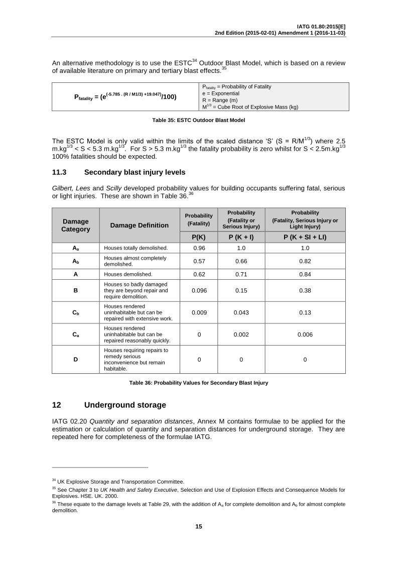
An alternative methodology is to use the ESTC34
Outdoor Blast Model, which is based on a review of available literature on primary and tertiary blast effects.
35
Pfatality = (e(-5.785 . (R / M1/3) +19.047)
/100)
Pfatality = Probability of Fatality
e = Exponential
R = Range (m)
M1/3
= Cube Root of Explosive Mass (kg)
Table 35: ESTC Outdoor Blast Model
The ESTC Model is only valid within the limits of the scaled distance ‘S’ (S = R/M
1/3) where 2.5
m.kg1/3
< S < 5.3 m.kg1/3
. For S > 5.3 m.kg1/3
the fatality probability is zero whilst for S < 2.5m.kg1/3
100% fatalities should be expected.
11.3 Secondary blast injury levels
Gilbert, Lees and Scilly developed probability values for building occupants suffering fatal, serious or light injuries. These are shown in Table 36.
36
Damage Category
Damage Definition
Probability
(Fatality)
Probability
(Fatality or Serious Injury)
Probability
(Fatality, Serious Injury or Light Injury)
P(K) P (K + I) P (K + SI + LI)
Aa Houses totally demolished. 0.96 1.0 1.0
Ab Houses almost completely demolished.
0.57 0.66 0.82
A Houses demolished. 0.62 0.71 0.84
B Houses so badly damaged they are beyond repair and require demolition.
0.096 0.15 0.38
Cb
Houses rendered uninhabitable but can be repaired with extensive work.
0.009 0.043 0.13
Ca Houses rendered uninhabitable but can be repaired reasonably quickly.
0 0.002 0.006
D
Houses requiring repairs to remedy serious inconvenience but remain habitable.
0 0 0
Table 36: Probability Values for Secondary Blast Injury
12 Underground storage
IATG 02.20 Quantity and separation distances, Annex M contains formulae to be applied for the estimation or calculation of quantity and separation distances for underground storage. They are repeated here for completeness of the formulae IATG.
34 UK Explosive Storage and Transportation Committee.
35 See Chapter 3 to UK Health and Safety Executive, Selection and Use of Explosion Effects and Consequence Models for
Explosives. HSE. UK. 2000. 36
These equate to the damage levels at Table 29, with the addition of Aa for complete demolition and Ab for almost complete demolition.

IATG 01.80:2015[E] 2nd Edition (2015-02-01) Amendment 1 (2016-11-03)
16
IBD = 77 x HD x LD1/3
Where:
HD = Hydraulic Diameter of Tunnel Mouth
LD1/3
= Loading Density (kg/m3)
HD = 4A/C
Where:
A = Cross-sectional Area of Tunnel Entrance (m2)
C = Circumference of Tunnel Entrance (m)
LD1/3
= NEQ (VCh+ VTunnel)
VCh= Chamber Volume (m3)
VTunnel = Tunnel Volume (m3)
Table 37: Inhabited Building Distance (IBD) (Blast from Tunnel Adit)
37 38
D = 27.4 x HD x LD1/3
As above
Table 38: Process Building Distance (PBD) (Blast from Tunnel Adit)
37 The distance in a non-axial direction may be reduced using a multiplication factor (MF), which should be derived from the
formula MF = 1 / (1 + (θ/56)2)0.76
, where θ is the angle from the tunnel centre line in degrees. 38
This is a simple approximation. A more accurate methodology is in AASPT-1, Chapter 3, Clause 3.3.4.1 (b) and (c).

IATG 01.80:2015[E] 2nd Edition (2015-02-01) Amendment 1 (2016-11-03)
17
Annex A (normative) References
The following normative documents contain provisions, which, through reference in this text, constitute provisions of this part of the guide. For dated references, subsequent amendments to, or revisions of, any of these publications do not apply. However, parties to agreements based on this part of the guide are encouraged to investigate the possibility of applying the most recent editions of the normative documents indicated below. For undated references, the latest edition of the normative document referred to applies. Members of ISO maintain registers of currently valid ISO or EN:
a) IATG 01.40:2015[E] Terms, glossary and definitions. UNODA. 2015.
The latest version/edition of these references should be used. The UN Office for Disarmament Affairs (UN ODA) holds copies of all references
39 used in this guide. A register of the latest
version/edition of the International Ammunition Technical Guidelines is maintained by UN ODA, and can be read on the IATG website: www.un.org/disarmament/un-saferguard/. National authorities, employers and other interested bodies and organisations should obtain copies before commencing conventional ammunition stockpile management programmes.
39 Where copyright permits.

IATG 01.80:2015[E] 2nd Edition (2015-02-01) Amendment 1 (2016-11-03)
18
Annex B (informative) References
The following informative documents contain provisions, which should also be consulted to provide further background information to the contents of this guide:
a) Explosion Hazards and Evaluation. W E Baker et al. Elsevier. (ISBN 0 444 42094 0). Amsterdam. 1983;
b) IATG 02.10:2015[E] Introduction to Risk Management Principles and Processes. UNODA. 2015;
c) Selection and Use of Explosion Effects and Consequence Models for Explosives. UK Health and Safety Executive. (ISBN 0 7176 1791 2). UK. 2000; and
d) Technical Note for Mine Action (TNMA) 10.20/01 Estimation of Explosion Danger Areas (Version 2.0). Geneva. GICHD.
The latest version/edition of these references should be used. The UN Office for Disarmament Affairs (UN ODA) holds copies of all references
40 used in this guide. A register of the latest
version/edition of the International Ammunition Technical Guidelines is maintained by UN ODA, and can be read on the IATG website: www.un.org/disarmament/un-saferguard/. National authorities, employers and other interested bodies and organisations should obtain copies before commencing conventional ammunition stockpile management programmes.
40 Where copyright permits.

IATG 01.80:2015[E] 2nd Edition (2015-02-01) Amendment 1 (2016-11-03)
19
Amendment record
Management of IATG amendments
The IATG guidelines are subject to formal review on a five-yearly basis, however this does not preclude amendments being made within these five-year periods for reasons of operational safety and efficiency or for editorial purposes.
As amendments are made to this IATG they will be given a number, and the date and general details of the amendment shown in the table below. The amendment will also be shown on the cover page of the IATG by the inclusion under the edition date of the phrase ‘incorporating amendment number(s) 1 etc.’
As the formal reviews of each IATG are completed new editions may be issued. Amendments up to the date of the new edition will be incorporated into the new edition and the amendment record table cleared. Recording of amendments will then start again until a further review is carried out.
The most recently amended, and thus extant, IATG will be the versions that are posted on the UN SaferGuard IATG website at www.un.org/disarmament/un-saferguard/.
Number Date Amendment Details
0 01 Feb 15 Release of Edition 2 of IATG.