Embed Size (px)
Citation preview
International Atomic Energy Agency
Patient Dose Management -Patient Dose Management -Equipment & Physical FactorsEquipment & Physical Factors
L 5
Lecture 5: Patient dose management 2Radiation Protection in Cardiology
Educational ObjectivesEducational Objectives
1. Physical factors & challenge to dose management
2. Understanding the role of operator in patient dose management
3. How to manage patient dose using equipment factors
Lecture 5: Patient dose management 3Radiation Protection in Cardiology
Physical factors and challenges to Physical factors and challenges to radiation managementradiation management
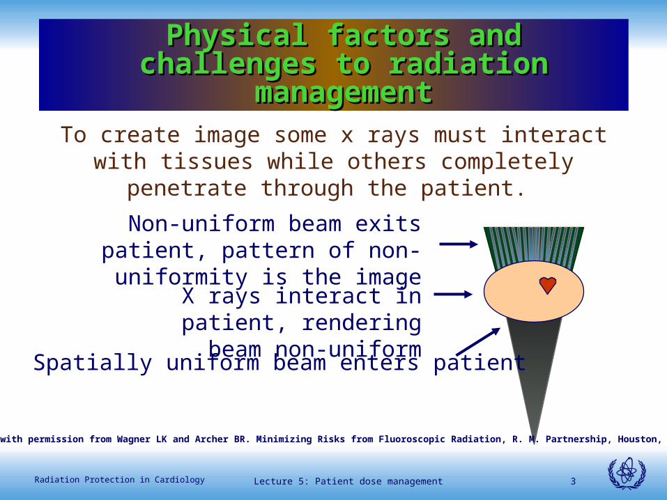
To create image some x rays must interact with tissues while others completely penetrate through the patient.
Spatially uniform beam enters patient
X rays interact in patient, rendering beam non-uniform
Non-uniform beam exits patient, pattern of non-uniformity is the
image
Reproduced with permission from Wagner LK and Archer BR. Minimizing Risks from Fluoroscopic Radiation, R. M. Partnership, Houston, TX 2004.
Lecture 5: Patient dose management 4Radiation Protection in Cardiology
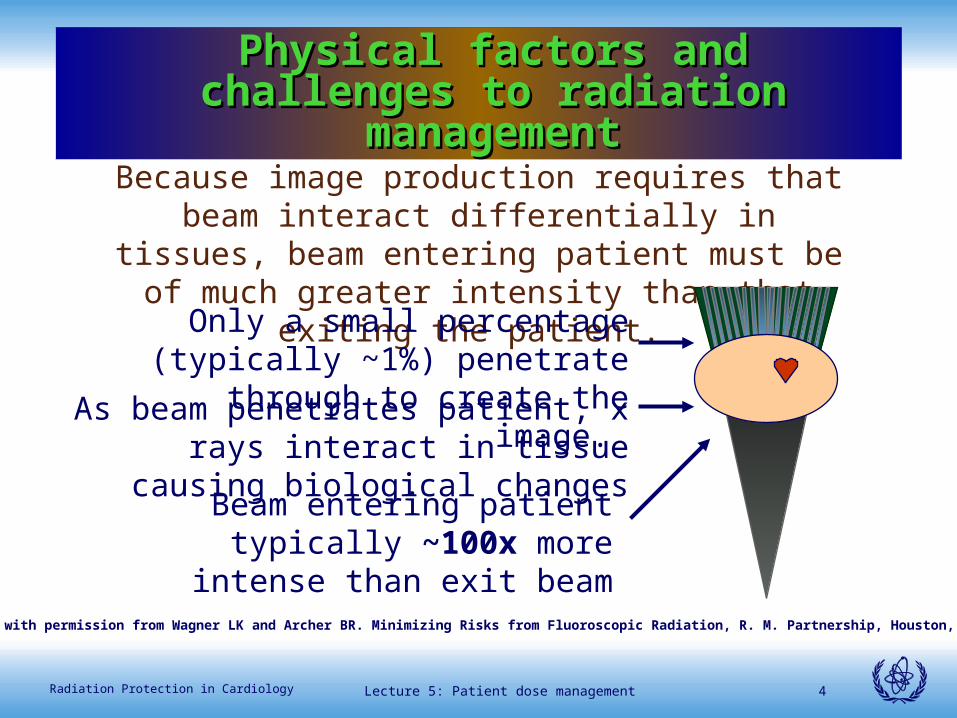
Because image production requires that beam interact differentially in tissues, beam entering patient must be of
much greater intensity than that exiting the patient.
Beam entering patient typically ~100x more intense than exit beam
As beam penetrates patient, x rays interact in tissue causing biological changes
Only a small percentage (typically ~1%) penetrate through to create the image.
Physical factors and challenges to Physical factors and challenges to radiation managementradiation management
Reproduced with permission from Wagner LK and Archer BR. Minimizing Risks from Fluoroscopic Radiation, R. M. Partnership, Houston, TX 2004.
Lecture 5: Patient dose management 5Radiation Protection in Cardiology
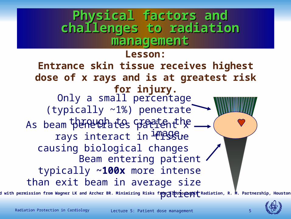
Lesson:Entrance skin tissue receives highest dose of x rays and
is at greatest risk for injury.
Beam entering patient typically ~100x more intense than exit beam in average size
patient
As beam penetrates patient x rays interact in tissue causing biological changes
Only a small percentage (typically ~1%) penetrate through to create the image.
Physical factors and challenges to Physical factors and challenges to radiation managementradiation management
Reproduced with permission from Wagner LK and Archer BR. Minimizing Risks from Fluoroscopic Radiation, R. M. Partnership, Houston, TX 2004.
Lecture 5: Patient dose management 6Radiation Protection in Cardiology
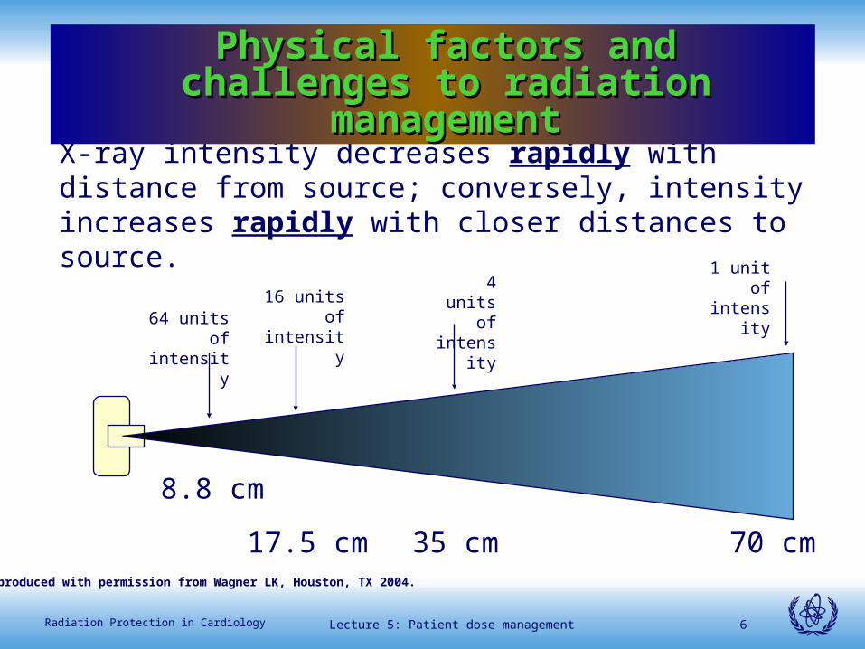
X-ray intensity decreases rapidly with distance from source; conversely, intensity increases rapidly with closer distances to source.
1 unit of intensity4 units of
intensity16 units of intensity64 units of
intensity
Physical factors and challenges to Physical factors and challenges to radiation managementradiation management
70 cm35 cm17.5 cm
8.8 cm
Reproduced with permission from Wagner LK, Houston, TX 2004.
Lecture 5: Patient dose management 7Radiation Protection in Cardiology
Lesson: Understanding how to take advantage of the rapid changes in dose rate with distance from source is
essential to good radiation management. Practical applications are demonstrated in following slides.
Physical factors and challenges to Physical factors and challenges to radiation managementradiation management
Lecture 5: Patient dose management 8Radiation Protection in Cardiology
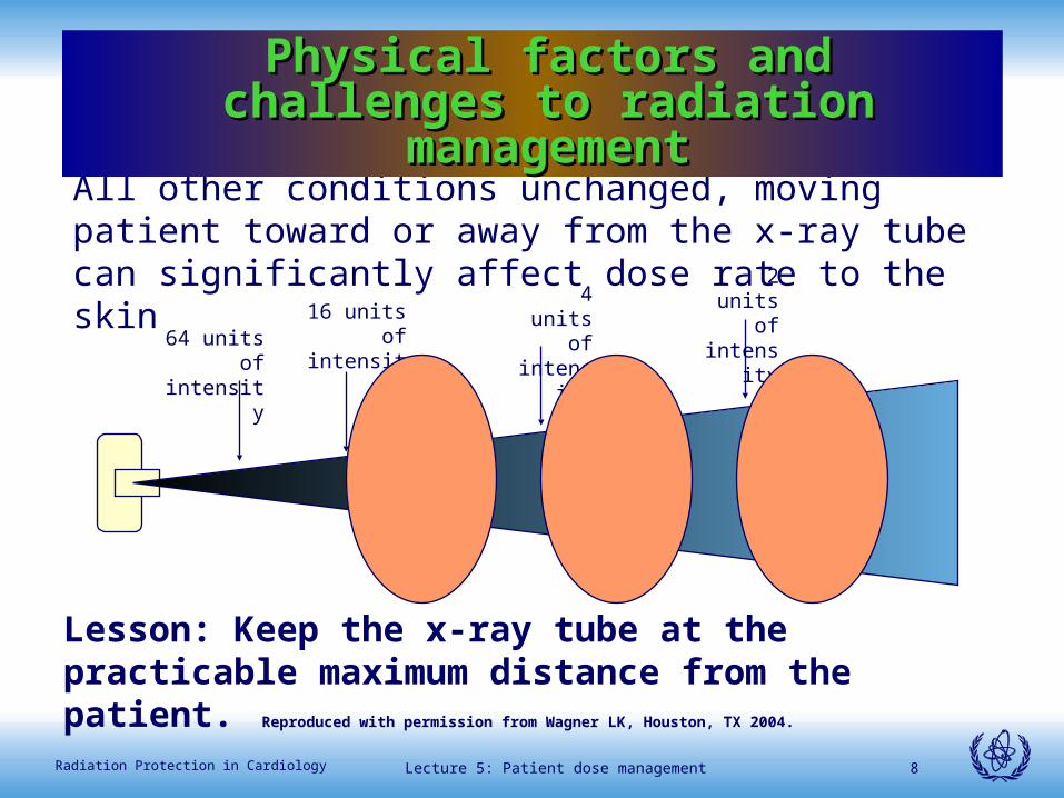
All other conditions unchanged, moving patient toward or away from the x-ray tube can significantly affect dose rate to the skin
Lesson: Keep the x-ray tube at the practicable maximum distance from the patient.
Physical factors and challenges to Physical factors and challenges to radiation managementradiation management
2 units of intensity4 units of
intensity16 units of intensity64 units of
intensity
Reproduced with permission from Wagner LK, Houston, TX 2004.
Lecture 5: Patient dose management 9Radiation Protection in Cardiology
Physical factors and challenges to radiation Physical factors and challenges to radiation managementmanagement
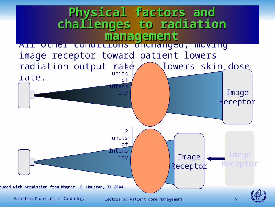
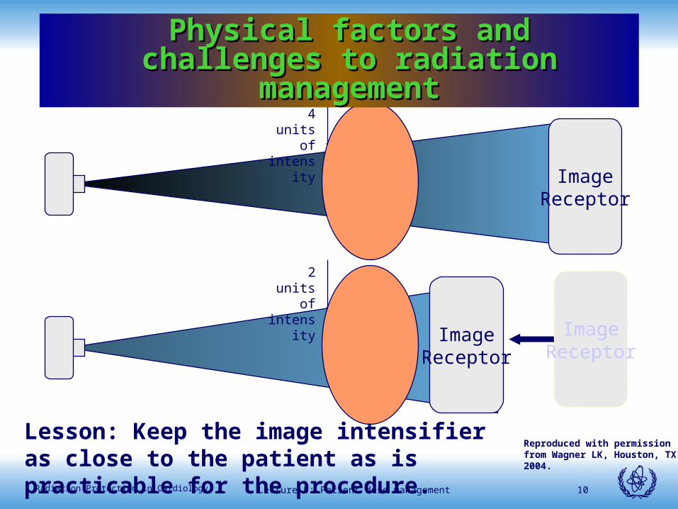
All other conditions unchanged, moving image receptor toward patient lowers radiation output rate and lowers skin dose rate.
4 units of intensity
ImageReceptor
2 units of intensity
ImageReceptor
ImageReceptor
Physical factors and challenges to Physical factors and challenges to radiation managementradiation management
Reproduced with permission from Wagner LK, Houston, TX 2004.
Lecture 5: Patient dose management 10Radiation Protection in Cardiology
Physical factors and challenges to radiation Physical factors and challenges to radiation managementmanagement
4 units of intensity
ImageReceptor
2 units of intensity
ImageReceptor
ImageReceptor
Physical factors and challenges to Physical factors and challenges to radiation managementradiation management
Lesson: Keep the image intensifier as close to the patient as is practicable for the procedure.
Reproduced with permission from Wagner LK, Houston, TX 2004.
Lecture 5: Patient dose management 11Radiation Protection in Cardiology
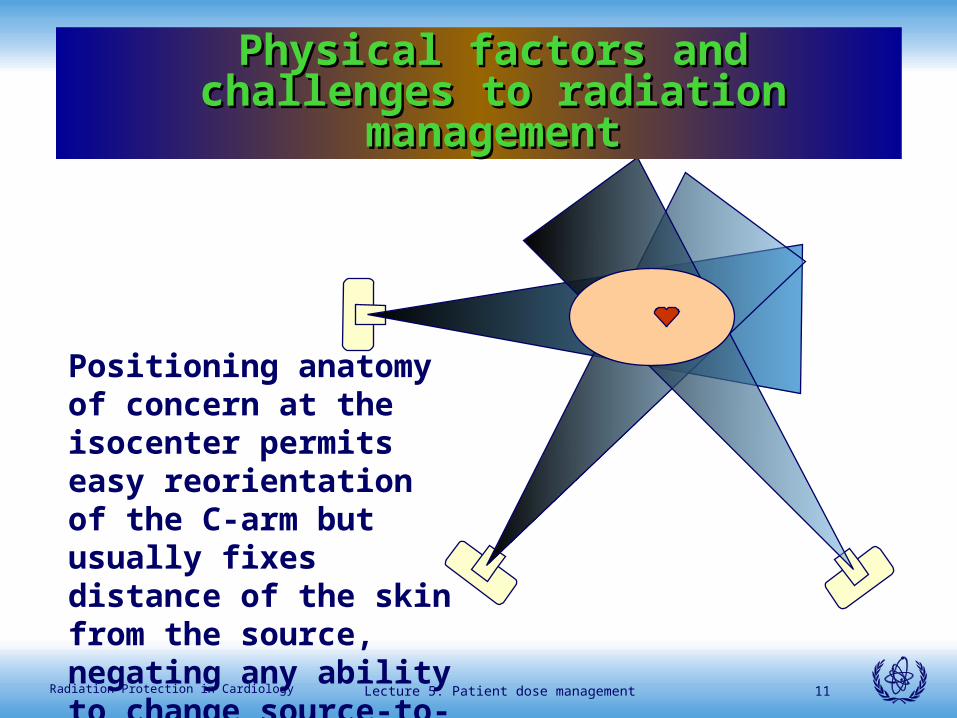
Positioning anatomy of concern at the isocenter permits easy reorientation of the C-arm but usually fixes distance of the skin from the source, negating any ability to change source-to-skin distance.
Physical factors and challenges to Physical factors and challenges to radiation managementradiation management
Lecture 5: Patient dose management 12Radiation Protection in Cardiology
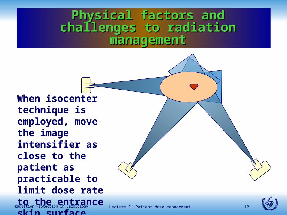
When isocenter technique is employed, move the image intensifier as close to the patient as practicable to limit dose rate to the entrance skin surface.
Physical factors and challenges to Physical factors and challenges to radiation managementradiation management
Lecture 5: Patient dose management 13Radiation Protection in Cardiology
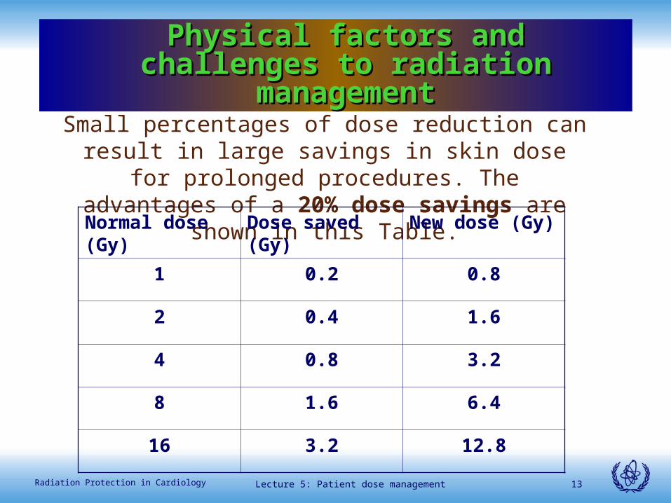
Small percentages of dose reduction can result in large savings in skin dose for prolonged procedures. The
advantages of a 20% dose savings are shown in this Table.
Normal dose (Gy)
Dose saved (Gy) New dose (Gy)
1 0.2 0.8
2 0.4 1.6
4 0.8 3.2
8 1.6 6.4
16 3.2 12.8
Physical factors and challenges to Physical factors and challenges to radiation managementradiation management
Lecture 5: Patient dose management 14Radiation Protection in Cardiology
Lesson: Actions that produce small changes in skin dose accumulation
result in important and considerable dose savings, sometimes resulting in the difference between severe and mild skin
dose effects or no effect.
Physical factors and challenges to Physical factors and challenges to radiation managementradiation management
Lecture 5: Patient dose management 15Radiation Protection in Cardiology
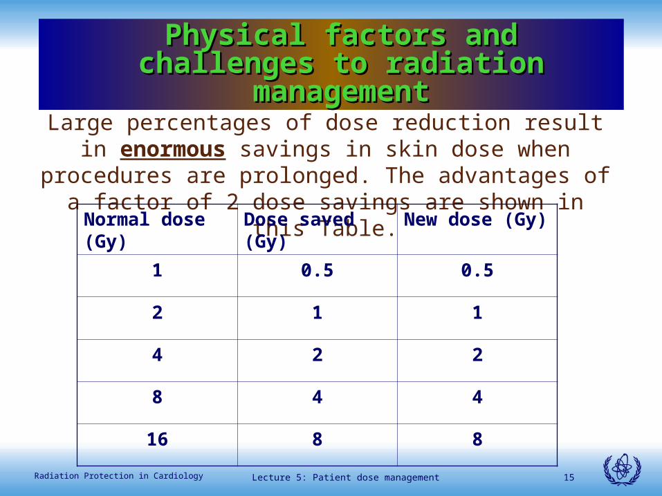
Large percentages of dose reduction result in enormous savings in skin dose when procedures are prolonged. The advantages of
a factor of 2 dose savings are shown in this Table.
Normal dose (Gy)
Dose saved (Gy) New dose (Gy)
1 0.5 0.5
2 1 1
4 2 2
8 4 4
16 8 8
Physical factors and challenges to Physical factors and challenges to radiation managementradiation management
Lecture 5: Patient dose management 16Radiation Protection in Cardiology
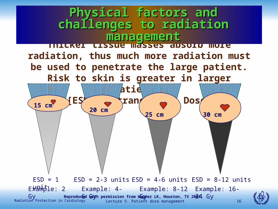
Thicker tissue masses absorb more radiation, thus much more radiation must be used to penetrate the large patient.
Risk to skin is greater in larger patients![ESD = Entrance Skin Dose]
15 cm20 cm
25 cm 30 cm
ESD = 1 unit ESD = 2-3 units ESD = 4-6 units ESD = 8-12 units
Example: 2 Gy Example: 4-6 Gy Example: 8-12 Gy Example: 16-24 Gy
Physical factors and challenges to Physical factors and challenges to radiation managementradiation management
Reproduced with permission from Wagner LK, Houston, TX 2004.
Lecture 5: Patient dose management 17Radiation Protection in Cardiology
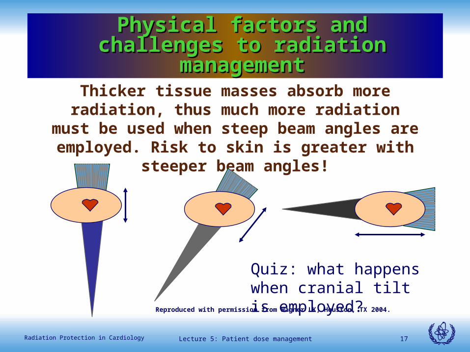
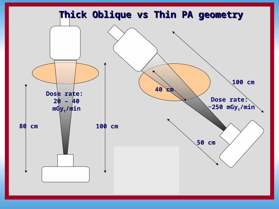
Thicker tissue masses absorb more radiation, thus much more radiation must be used when steep beam
angles are employed. Risk to skin is greater with steeper beam angles!
Physical factors and challenges to Physical factors and challenges to radiation managementradiation management
Quiz: what happens when cranial tilt is employed?
Reproduced with permission from Wagner LK, Houston, TX 2004.
International Atomic Energy Agency
100 cm80 cm
Dose rate: 20 – 40 mGyt/min
Thick Oblique vs Thin PA geometryThick Oblique vs Thin PA geometry
100 cm
50 cm
Dose rate: ~250 mGyt/min
40 cm
Lecture 5: Patient dose management 19Radiation Protection in Cardiology
A word about collimationA word about collimation
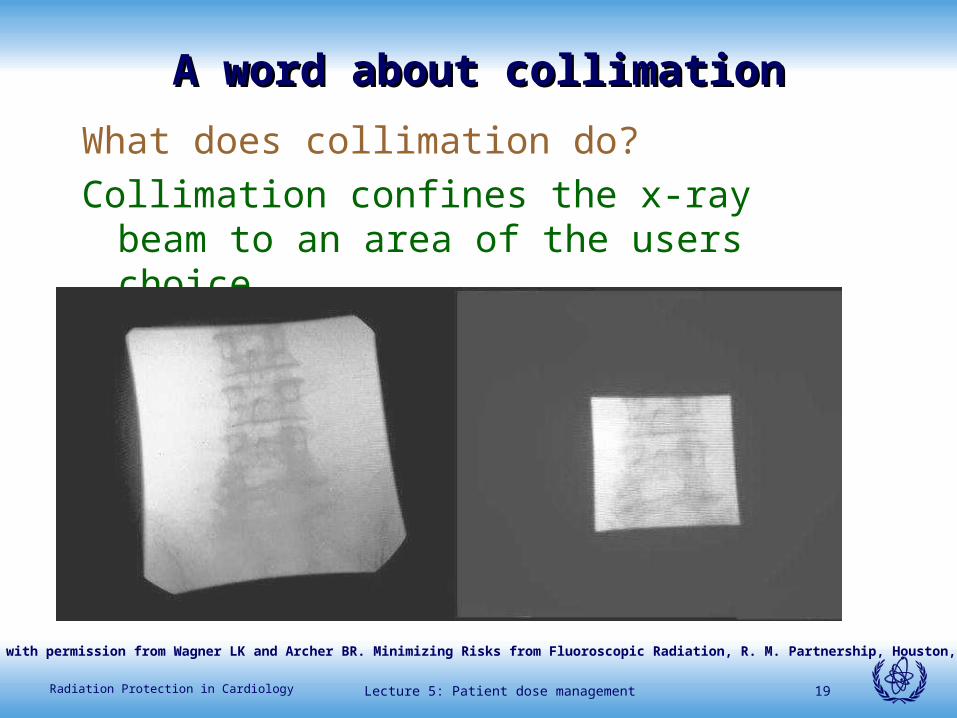
What does collimation do?
Collimation confines the x-ray beam to an area of the users choice.
Reproduced with permission from Wagner LK and Archer BR. Minimizing Risks from Fluoroscopic Radiation, R. M. Partnership, Houston, TX 2004.
Lecture 5: Patient dose management 20Radiation Protection in Cardiology
A word about collimationA word about collimation
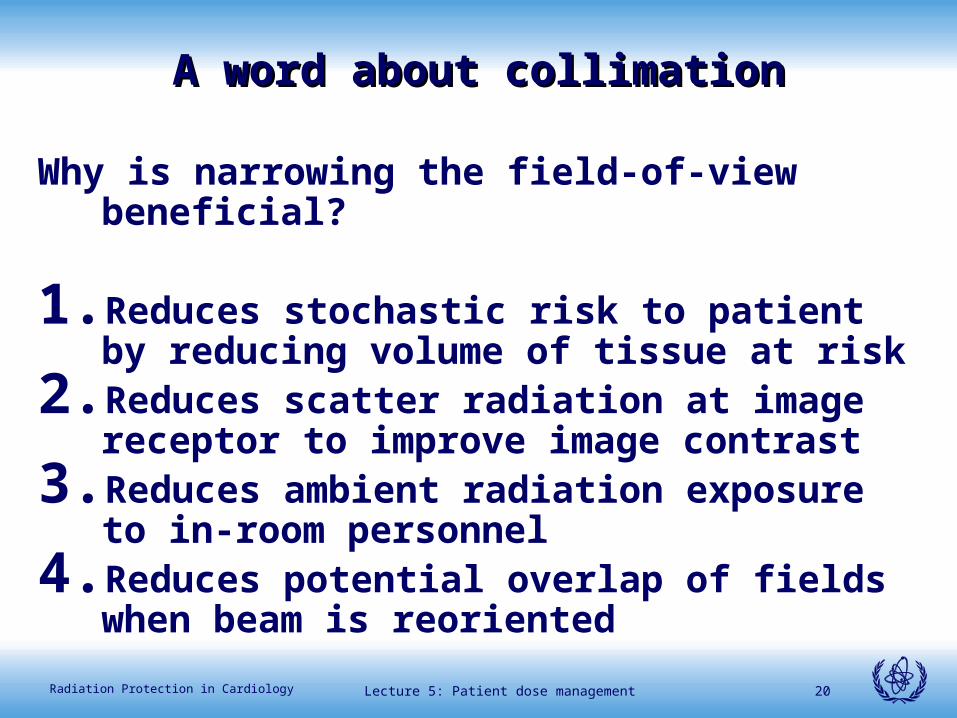
Why is narrowing the field-of-view beneficial?
1. Reduces stochastic risk to patient by reducing volume of tissue at risk
2. Reduces scatter radiation at image receptor to improve image contrast
3. Reduces ambient radiation exposure to in-room personnel
4. Reduces potential overlap of fields when beam is reoriented
Lecture 5: Patient dose management 21Radiation Protection in Cardiology
A word about collimationA word about collimation
What collimation does not do –
It does NOT reduce dose to the exposed portion of patient’s skin
In fact, dose at the skin entrance In fact, dose at the skin entrance site increases, sometimes by a site increases, sometimes by a factor of 50% or so, depending factor of 50% or so, depending on conditions.on conditions.
Lecture 5: Patient dose management 22Radiation Protection in Cardiology
Physical factors and challenges to radiation Physical factors and challenges to radiation managementmanagement
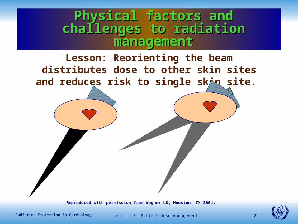
Lesson: Reorienting the beam distributes dose to other skin sites and reduces risk to single skin site.
Physical factors and challenges to Physical factors and challenges to radiation managementradiation management
Reproduced with permission from Wagner LK, Houston, TX 2004.
Lecture 5: Patient dose management 23Radiation Protection in Cardiology
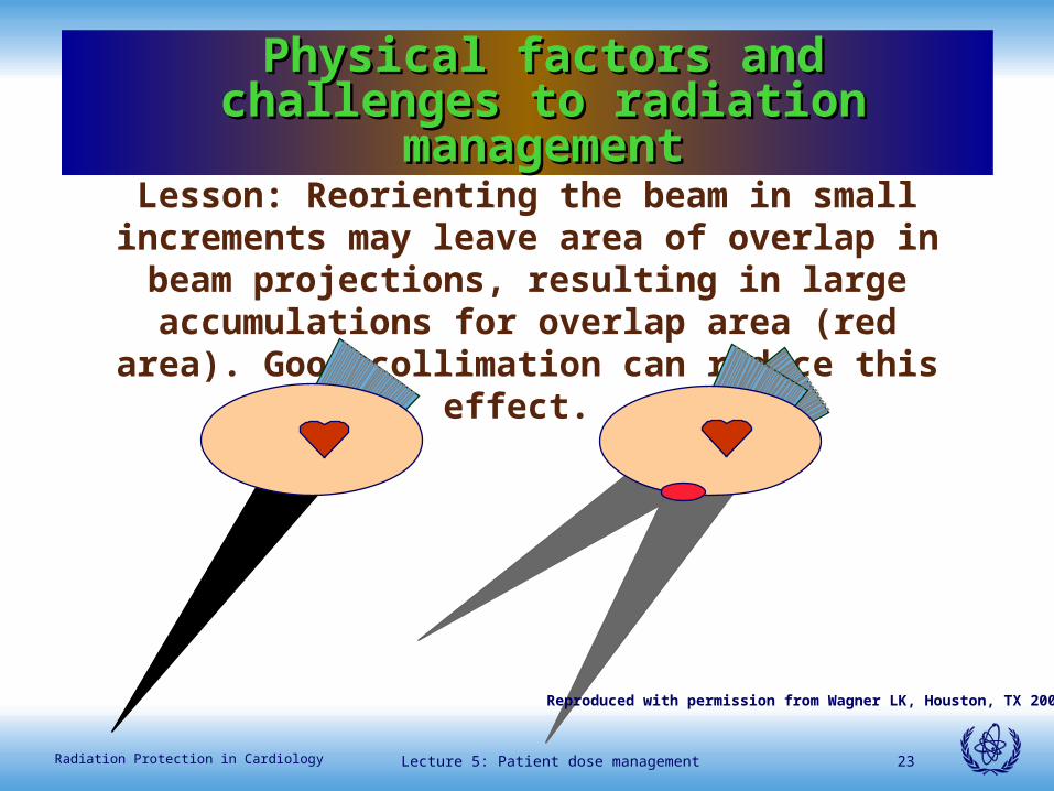
Lesson: Reorienting the beam in small increments may leave area of overlap in beam projections, resulting in large accumulations for overlap area (red area). Good
collimation can reduce this effect.
Physical factors and challenges to Physical factors and challenges to radiation managementradiation management
Reproduced with permission from Wagner LK, Houston, TX 2004.
Lecture 5: Patient dose management 24Radiation Protection in Cardiology
Physical factors and challenges to radiation Physical factors and challenges to radiation managementmanagement
Conclusion: Orientation of beam is usually determined and fixed by clinical need. When
practical, reorientation of the beam to a new skin site can lessen risk to skin. Overlapping areas
remaining after reorientation are still at high risk. Good collimation reduces the overlap area.
Physical factors and challenges to Physical factors and challenges to radiation managementradiation management
Lecture 5: Patient dose management 25Radiation Protection in Cardiology
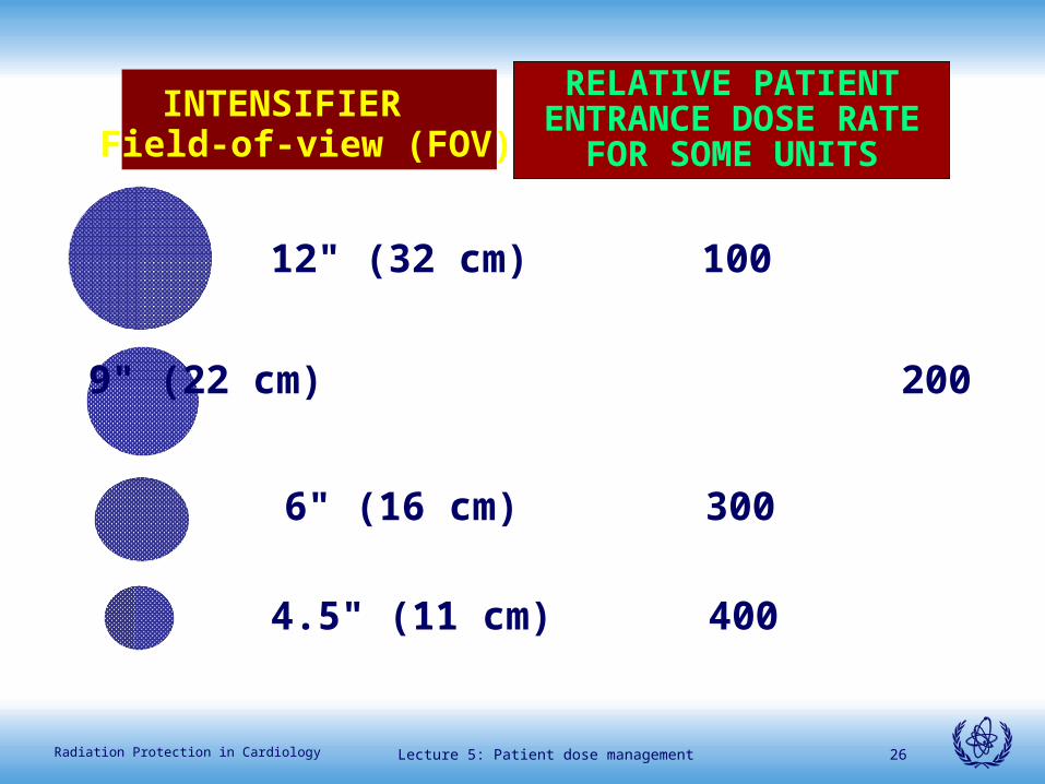
Dose rate dependence on image receptor
field-of-view or magnification mode.
Lecture 5: Patient dose management 26Radiation Protection in Cardiology
INTENSIFIER Field-of-view (FOV)
RELATIVE PATIENT ENTRANCE DOSE RATE
FOR SOME UNITS
12" (32 cm) 100
9" (22 cm) 200
6" (16 cm) 300
4.5" (11 cm) 400
Lecture 5: Patient dose management 27Radiation Protection in Cardiology
• How input dose rate changes with different FOVs depends on machine design and must be verified by a medical physicist to properly incorporate use into procedures.
• A typical rule is to use the least magnification necessary for the procedure, but this does not apply to all machines.
Lecture 5: Patient dose management 28Radiation Protection in Cardiology
Lecture 5: Patient dose management 29Radiation Protection in Cardiology
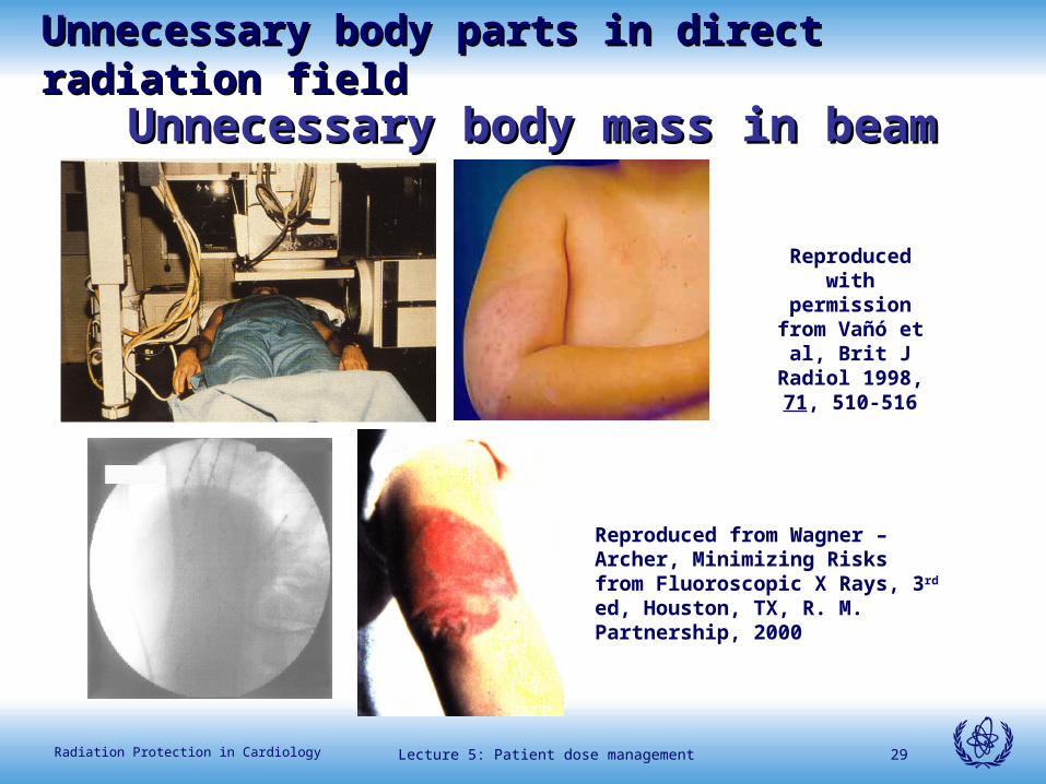
Unnecessary body mass in beamUnnecessary body mass in beam
Reproduced from Wagner – Archer, Minimizing Risks from Fluoroscopic X Rays, 3rd ed, Houston, TX, R. M. Partnership, 2000
Reproduced with permission from Vañó et al, Brit J Radiol 1998, 71,
510-516
Unnecessary body parts in direct radiation fieldUnnecessary body parts in direct radiation field
Lecture 5: Patient dose management 30Radiation Protection in Cardiology
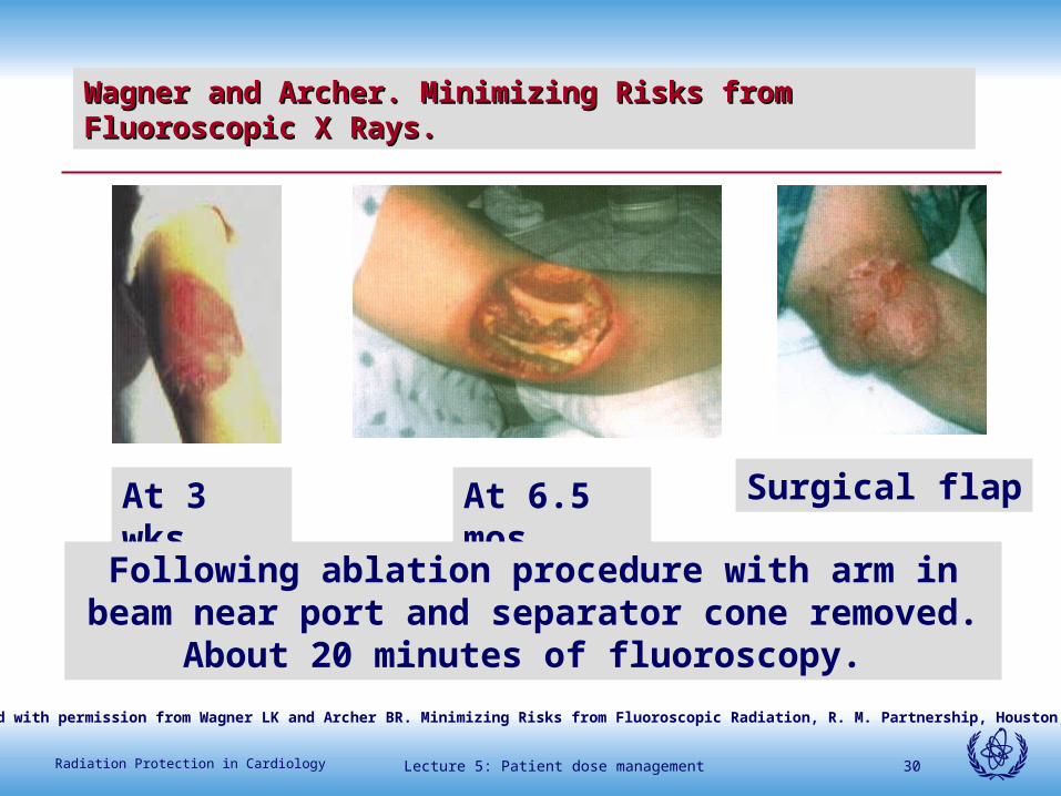
Wagner and Archer. Minimizing Risks from Fluoroscopic X Rays. Wagner and Archer. Minimizing Risks from Fluoroscopic X Rays.
At 3 wks At 6.5 mos Surgical flap
Following ablation procedure with arm in beam near port and separator cone removed. About 20 minutes of
fluoroscopy.
Reproduced with permission from Wagner LK and Archer BR. Minimizing Risks from Fluoroscopic Radiation, R. M. Partnership, Houston, TX 2004.
Lecture 5: Patient dose management 31Radiation Protection in Cardiology
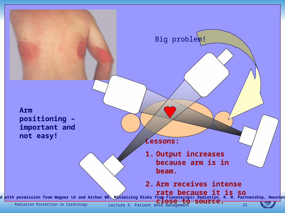
Big problem!
Lessons:
1. Output increases because arm is in beam.
2. Arm receives intense rate because it is so close to source.
Arm positioning – important and not easy!
Reproduced with permission from Wagner LK and Archer BR. Minimizing Risks from Fluoroscopic Radiation, R. M. Partnership, Houston, TX 2004.
Lecture 5: Patient dose management 32Radiation Protection in Cardiology
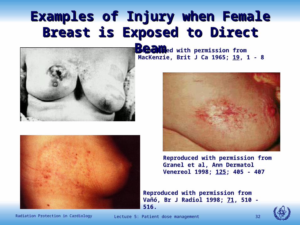
Reproduced with permission from MacKenzie, Brit J Ca 1965; 19, 1 - 8
Reproduced with permission from Vañó, Br J Radiol 1998; 71, 510 - 516.
Reproduced with permission from Granel et al, Ann Dermatol Venereol 1998; 125; 405 - 407
Examples of Injury when Female Examples of Injury when Female Breast is Exposed to Direct BeamBreast is Exposed to Direct Beam
Lecture 5: Patient dose management 33Radiation Protection in Cardiology
Lesson Learned:
• Keep unnecessary body parts, especially arms and female breasts, out of the direct beam.
Lecture 5: Patient dose management 34Radiation Protection in Cardiology
Lecture 5: Patient dose management 35Radiation Protection in Cardiology
Beam energy:
X rays used in fluoroscopy systems have a spectrum of energies that can be controlled to manipulate image quality.
How a system manipulates the spectrum depends on how the system is designed.
Some systems permit the operator to select filtration schemes
Design of fluoroscopic equipment for Design of fluoroscopic equipment for proper radiation controlproper radiation control
Lecture 5: Patient dose management 36Radiation Protection in Cardiology
0
0.2
0.4
0.6
0.8
1
0 10 20 30 40 50 60 70 80 90
Photon Energy (keV)
Rel
ativ
e in
ten
sity
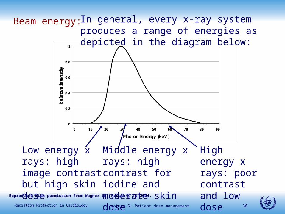
Beam energy: In general, every x-ray system produces a range of energies as depicted in the diagram below:
Low energy x rays: high image contrast but high skin dose
Middle energy x rays: high contrast for iodine and moderate skin dose
High energy x rays: poor contrast and low dose
Reproduced with permission from Wagner LK, Houston, TX 2004.
Lecture 5: Patient dose management 37Radiation Protection in Cardiology
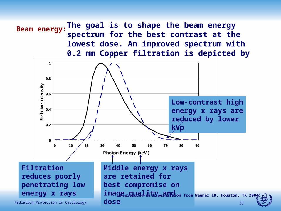
Beam energy: The goal is to shape the beam energy spectrum for the best contrast at the lowest dose. An improved spectrum with 0.2 mm Copper filtration is depicted by the dashes:
Middle energy x rays are retained for best compromise on image quality and dose
0
0.2
0.4
0.6
0.8
1
0 10 20 30 40 50 60 70 80 90
Photon Energy (keV)
Rel
ativ
e in
ten
sity
Low-contrast high energy x rays are reduced by lower kVp
Filtration reduces poorly penetrating low energy x rays
Reproduced with permission from Wagner LK, Houston, TX 2004.
Lecture 5: Patient dose management 38Radiation Protection in Cardiology
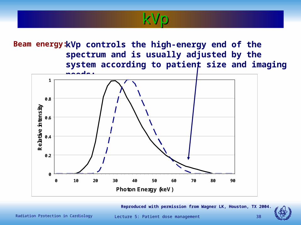
Beam energy: kVp controls the high-energy end of the spectrum and is usually adjusted by the system according to patient size and imaging needs:
0
0.2
0.4
0.6
0.8
1
0 10 20 30 40 50 60 70 80 90
Photon Energy (keV)
Rel
ativ
e in
ten
sity
kVpkVp
Reproduced with permission from Wagner LK, Houston, TX 2004.
Lecture 5: Patient dose management 39Radiation Protection in Cardiology
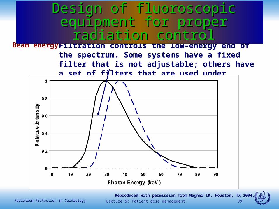
Beam energy:Filtration controls the low-energy end of the spectrum. Some systems have a fixed filter that is not adjustable; others have a set of filters that are used under differing imaging schemes.
Physical factors and challenges to Physical factors and challenges to radiation managementradiation management
0
0.2
0.4
0.6
0.8
1
0 10 20 30 40 50 60 70 80 90
Photon Energy (keV)
Rel
ativ
e in
ten
sity
Design of fluoroscopic equipment for Design of fluoroscopic equipment for proper radiation controlproper radiation control
Reproduced with permission from Wagner LK, Houston, TX 2004.
Lecture 5: Patient dose management 40Radiation Protection in Cardiology
Physical factors and challenges to Physical factors and challenges to radiation managementradiation management
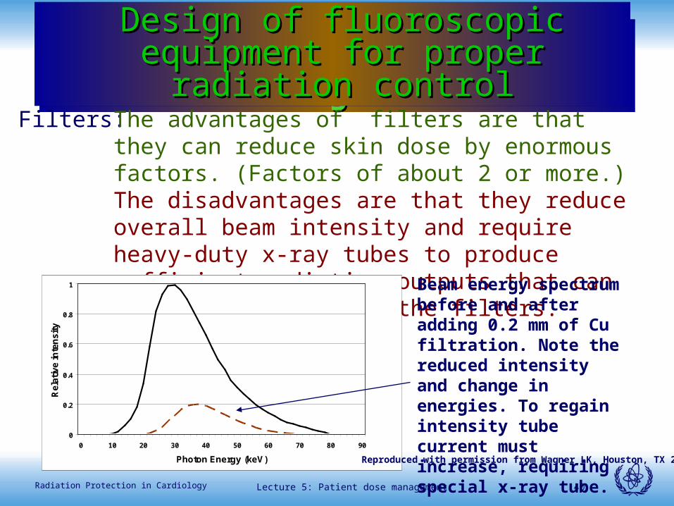
Filters: The advantages of filters are that they can reduce skin dose by enormous factors. (Factors of about 2 or more.) The disadvantages are that they reduce overall beam intensity and require heavy-duty x-ray tubes to produce sufficient radiation outputs that can adequately penetrate the filters.
0
0.2
0.4
0.6
0.8
1
0 10 20 30 40 50 60 70 80 90
Photon Energy (keV)
Rel
ativ
e in
ten
sity
Beam energy spectrum before and after adding 0.2 mm of Cu filtration. Note the reduced intensity and change in energies. To regain intensity tube current must increase, requiring special x-ray tube.
Design of fluoroscopic equipment for Design of fluoroscopic equipment for proper radiation controlproper radiation control
Reproduced with permission from Wagner LK, Houston, TX 2004.
Lecture 5: Patient dose management 41Radiation Protection in Cardiology
Physical factors and challenges to Physical factors and challenges to radiation managementradiation management
If filters reduce intensity excessively, image quality is compromised, usually in the form of increased motion blurring or excessive quantum mottle.
Lesson: To use filters optimally, systems must be designed to produce appropriate beam intensities with variable filter options that depend on patient size and the imaging task.
Design of fluoroscopic equipment for Design of fluoroscopic equipment for proper radiation controlproper radiation control
Lecture 5: Patient dose management 42Radiation Protection in Cardiology
Physical factors and challenges to Physical factors and challenges to radiation managementradiation management
Modern fluoroscopy systems employ special filtration to reduce skin dose and, for detail cardiologic work, employ a set of filters with varying properties that are switched by the system according to imaging needs. Some schemes are selectable by the user.
Conclusion: Users must establish protocols for use of manufacturer supplied filter options that provide the best compromise in patient dose and image quality for each machine employed.
Design of fluoroscopic equipment for Design of fluoroscopic equipment for proper radiation controlproper radiation control
Lecture 5: Patient dose management 43Radiation Protection in Cardiology
Physical factors and challenges to Physical factors and challenges to radiation managementradiation management
Fluoroscopic kVp:
Fluoroscopic kVp in modern systems is controlled by the system. The user might be able to influence the way the system works:
1. By selecting various dose rate selection options
1. By selecting a kVp floor
Design of fluoroscopic equipment for Design of fluoroscopic equipment for proper radiation controlproper radiation control
Lecture 5: Patient dose management 44Radiation Protection in Cardiology
Physical factors and challenges to Physical factors and challenges to radiation managementradiation management
Lessons regarding kVp floor:
1. Available on a few machines
2. Sets kVp below which system does not operate
3. Unit usually operates at floor kVp unless regulatory dose rates are challenged due to poor beam penetration.
4. If set too low, dose rates are always excessive because system always operates at maximum rates
Design of fluoroscopic equipment for Design of fluoroscopic equipment for proper radiation controlproper radiation control
Lecture 5: Patient dose management 45Radiation Protection in Cardiology
Physical factors and challenges to Physical factors and challenges to radiation managementradiation management
The kVp floor:
Lesson:
Be sure kVp floor, if available, is set at appropriately high value to assure system operates at moderate to low dose rates.
Design of fluoroscopic equipment for Design of fluoroscopic equipment for proper radiation controlproper radiation control
Lecture 5: Patient dose management 46Radiation Protection in Cardiology
Lecture 5: Patient dose management 47Radiation Protection in Cardiology
Design of fluoroscopic equipment for proper radiation Design of fluoroscopic equipment for proper radiation controlcontrol
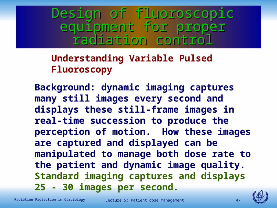
Understanding Variable Pulsed Fluoroscopy
Background: dynamic imaging captures many still images every second and displays these still-frame images in real-time succession to produce the perception of motion. How these images are captured and displayed can be manipulated to manage both dose rate to the patient and dynamic image quality. Standard imaging captures and displays 25 - 30 images per second.
Design of fluoroscopic equipment for Design of fluoroscopic equipment for proper radiation controlproper radiation control
Lecture 5: Patient dose management 48Radiation Protection in Cardiology
30 images in 1 second
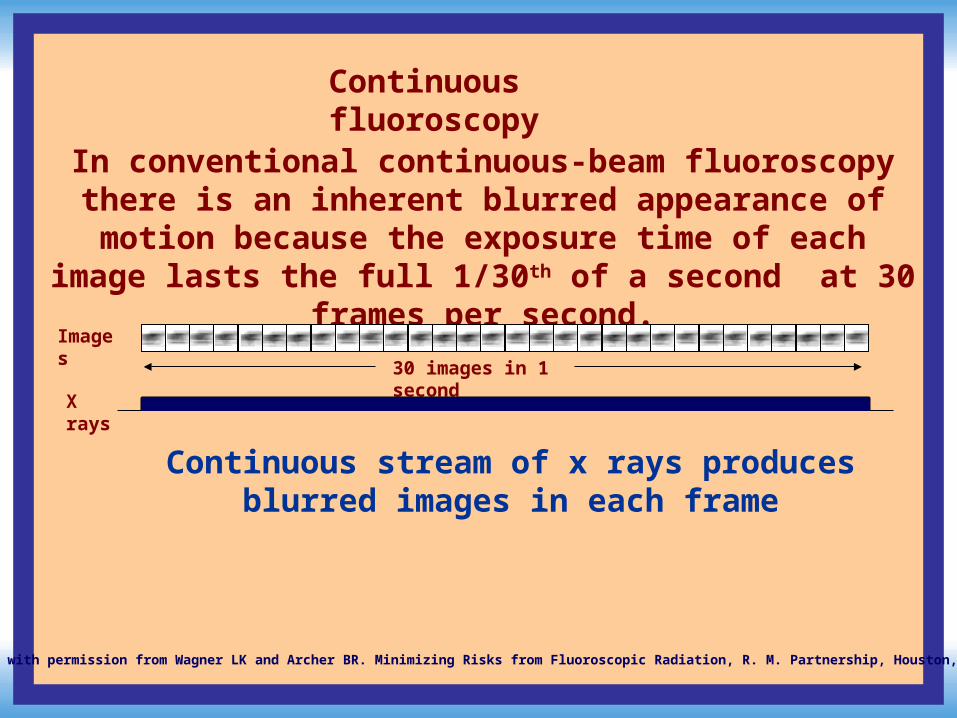
Continuous fluoroscopy
X rays
In conventional continuous-beam fluoroscopy there is an inherent blurred appearance of motion because the exposure
time of each image lasts the full 1/30th of a second at 30 frames per second.
Continuous stream of x rays produces blurred images in each frame
Images
Reproduced with permission from Wagner LK and Archer BR. Minimizing Risks from Fluoroscopic Radiation, R. M. Partnership, Houston, TX 2004.
Lecture 5: Patient dose management 49Radiation Protection in Cardiology
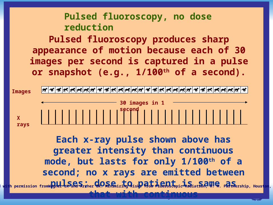
Each x-ray pulse shown above has greater intensity than continuous mode, but lasts for only 1/100th of a
second; no x rays are emitted between pulses; dose to patient is same as that with continuous
Pulsed fluoroscopy, no dose reduction
Images
Pulsed fluoroscopy produces sharp appearance of motion because each of 30 images per second is captured in a pulse
or snapshot (e.g., 1/100th of a second).
X rays
30 images in 1 second
Reproduced with permission fromWagner LK and Archer BR. Minimizing Risks from Fluoroscopic Radiation, R. M. Partnership, Houston, TX 2004.
Lecture 5: Patient dose management 50Radiation Protection in Cardiology
Physical factors and challenges to radiation Physical factors and challenges to radiation managementmanagement
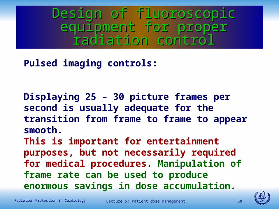
Pulsed imaging controls:
Displaying 25 – 30 picture frames per second is usually adequate for the transition from frame to frame to appear smooth. This is important for entertainment purposes, but not necessarily required for medical procedures. Manipulation of frame rate can be used to produce enormous savings in dose accumulation.
Design of fluoroscopic equipment for Design of fluoroscopic equipment for proper radiation controlproper radiation control
Lecture 5: Patient dose management 51Radiation Protection in Cardiology
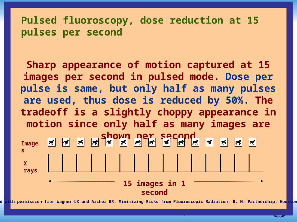
Pulsed fluoroscopy, dose reduction at 15 pulses per second
Sharp appearance of motion captured at 15 images per second in pulsed mode. Dose per pulse is same, but only half as many pulses are used, thus dose is reduced by 50%. The tradeoff is a slightly choppy appearance in motion since only half as many
images are shown per second
Images
X rays
15 images in 1 second
Reproduced with permission from Wagner LK and Archer BR. Minimizing Risks from Fluoroscopic Radiation, R. M. Partnership, Houston, TX 2004.
Lecture 5: Patient dose management 52Radiation Protection in Cardiology
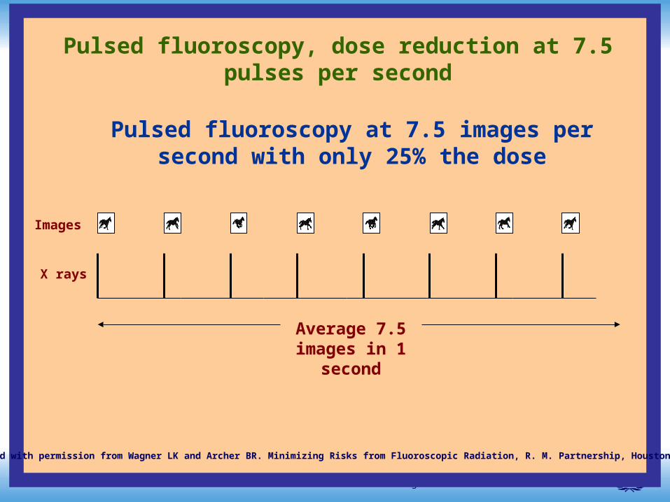
Pulsed fluoroscopy at 7.5 images per second with only 25% the dose
Pulsed fluoroscopy, dose reduction at 7.5 pulses per second
Images
X rays
Average 7.5 images in 1
second
Reproduced with permission from Wagner LK and Archer BR. Minimizing Risks from Fluoroscopic Radiation, R. M. Partnership, Houston, TX 2004.
Lecture 5: Patient dose management 53Radiation Protection in Cardiology
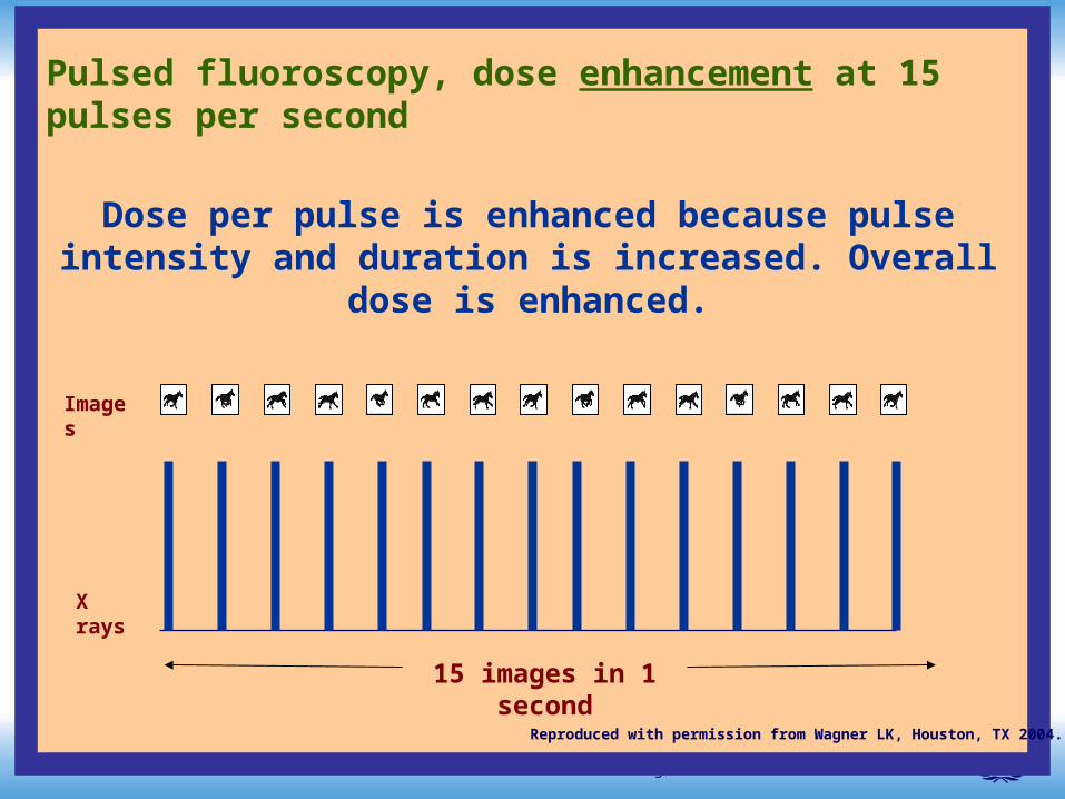
Pulsed fluoroscopy, dose enhancement at 15 pulses per second
Dose per pulse is enhanced because pulse intensity and duration is increased. Overall dose is enhanced.
Images
X rays
15 images in 1 second
Reproduced with permission from Wagner LK, Houston, TX 2004.
Lecture 5: Patient dose management 54Radiation Protection in Cardiology
Design of fluoroscopic equipment for proper radiation controlDesign of fluoroscopic equipment for proper radiation control
Lesson: Variable pulsed fluoroscopy is an important tool to manage radiation dose to patients but the actual effect on dose can be to enhance, decrease or maintain dose levels. The actual effect must be measured by a qualified physicist so that variable pulsed fluoroscopy can be properly employed.
Design of fluoroscopic equipment for Design of fluoroscopic equipment for proper radiation controlproper radiation control
Lecture 5: Patient dose management 55Radiation Protection in Cardiology
Quantum Noise Control
Lecture 5: Patient dose management 56Radiation Protection in Cardiology
Physical factors and challenges to radiation Physical factors and challenges to radiation managementmanagement
Quantum noise controls:
Quantum noise controls control the clarity of the image by changing the dose rate to the image receptor. This requires that dose rate to the patient be manipulated.
They come in two forms – conventional dose level controls and high level controls. Conventional level controls permit the adjustment of dose rates only within the low-dose rate regulatory limits. High level controls permit the adjustment of dose rates beyond these limits.
Design of fluoroscopic equipment for Design of fluoroscopic equipment for proper radiation controlproper radiation control
Lecture 5: Patient dose management 57Radiation Protection in Cardiology
Physical factors and challenges to radiation Physical factors and challenges to radiation managementmanagement
Quantum noise controls:
Lessons :
Adjust quantum noise options so that image quality is adequate and not excessive for the task at hand. Limit the use of high-level control to very brief episodes when fine detail is required. Overuse of high-level controls as a surrogate for conventional fluoroscopy can be dangerous and can result in very high dose accumulations and possible severe injury in a matter of minutes!
Design of fluoroscopic equipment for Design of fluoroscopic equipment for proper radiation controlproper radiation control
Lecture 5: Patient dose management 58Radiation Protection in Cardiology
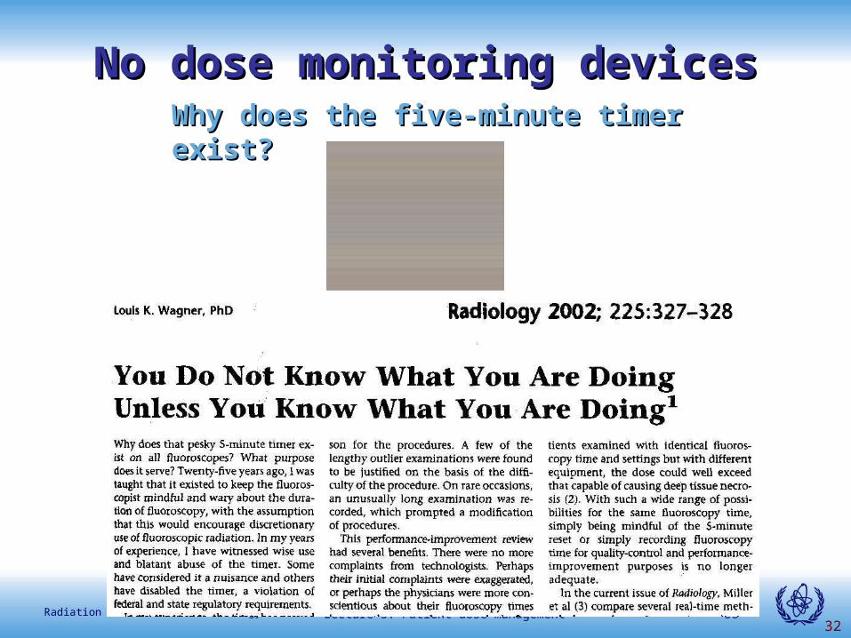
32
Why does the five-minute timer exist? Why does the five-minute timer exist?
No dose monitoring devicesNo dose monitoring devices
Lecture 5: Patient dose management 59Radiation Protection in Cardiology
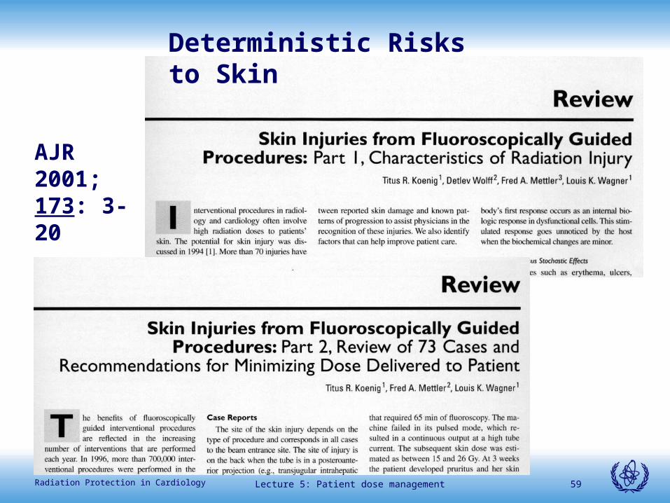
Deterministic Risks to Skin
AJR 2001; 173: 3-20