Embed Size (px)
Citation preview

International Communications in Heat and Mass Transfer 37 (2010) 1106–1114
Contents lists available at ScienceDirect
International Communications in Heat and Mass Transfer
j ourna l homepage: www.e lsev ie r.com/ locate / ichmt
Energy and exergy analyses in convective drying process of multi-layered porouspacked bed☆
Ratthasak Prommas, Pornthip Keangin, Phadungsak Rattanadecho ⁎Research Center of Microwave Utilization in Engineering (R.C.M.E.), Faculty of Engineering, Thammasat University, Khlong Luang, Pathumthani, Thailand 12120
☆ Communicated by W.J. Minkowycz.⁎ Corresponding author.
E-mail address: [email protected] (P. Rattanad
0735-1933/$ – see front matter © 2010 Elsevier Ltd. Aldoi:10.1016/j.icheatmasstransfer.2010.06.013
a b s t r a c t
a r t i c l e i n f oAvailable online 9 July 2010
Keywords:Energy utilizationExergy efficiencyConvective dryingMulti-layered porous
This paper is concerned with the investigation of the energy and exergy analyses in convective dryingprocess of multi-layered porous media. The drying experiments were conducted to find the effects of multi-layered porous particle size and thermodynamics conditions on energy and exergy profiles. An energyanalysis was performed to estimate the energy utilization by applying the first law of thermodynamics. Anexergy analysis was performed to determine the exergy inlet, exergy outlet, exergy losses during the dryingprocess by applying the second law of thermodynamics. The results show that the energy utilization ratio(EUR) and the exergy efficiency depend on the particle size as well as the hydrodynamic properties andthe layered structure, by considering the interference between capillary flow and vapor diffusion in themulti-layered packed bed.
echo).
l rights reserved.
© 2010 Elsevier Ltd. All rights reserved.
1. Introduction
Drying is a thermal process in which heat and moisture transferoccur simultaneously. Heat is transferred by convection from heatedair to the product to raise the temperatures of both the solid andmoisture that is present. Moisture transfers occurs as the moisturetravels to the evaporative surface of the product and then it evaporateinto the circulating air as water vapor, are necessary for processdesign, optimization, energy integration, and control [1,2]. The heatand moisture transfer rates are therefore related to the velocity,temperature and type of product with the circulating drying air.Thermal drying has been recognized as an important unit operation asit is energy intensive and has a decisive effect on the quality of mostproducts that are dried commercially [3,4].
Drying of porous solids is a subject of significant scientific andtechnological interest in a number of industrial applications includingcoatings, food, paper, textile, wood, ceramics, building materials,granular materials, electronic devices and pharmaceuticals [5].
Drying of porous materials is a problem of coupled heat and masstransport in a multiphase systemwhich undergoes structural changesand shrinkage during the process. As drying proceeds, themechanismsof water migration and all the transport properties change [6].Nevertheless, most of the models describing the drying of foodstuffsare constructed on the basis of theories commonlyused indealingwith
conventional porous materials, and without acknowledging thefeatures which make this particular problem unusual.
The traditional thermodynamics method of assessing processesinvolving the physical or chemical processing of materials withaccompanying transfer and transformation of energy is by thecompletion of an energy balance which is based on the first law ofthermodynamics. The first law analysis is used to reduce heat lossesor enhance heat recovery. Meanwhile, it gives no information on thedegradation of the useful energy that occurs within the processequipment [7]. The exergy of an energy form or a substance is ameasure of its usefulness or quality or potential change [8]. Exergy isdefined as themaximumwork, which can be produced by a system or aflow of matter or energy and it comes to equilibrium with a specifiedreference environment (dead state) [9]. Unlike energy, exergy isconserved only during ideal processes and destroyed due to irreversi-bilities in real processes [10].
The features of exergy are identified to highlight its importancein a wide range of applications [11]. Exergy analysis has beenincreasingly useful as a tool in the design, assessment, optimizationand improvement of energy systems. It can be applied on both systemand component levels. Exergy analysis leads to a better understandingof the influence of thermodynamics phenomena on effective process,comparison of the importance of different thermodynamics factors,and the determination of the most effective ways of improving theprocess [12]. As regards the exergy analyses of drying processes, somework has been carried out in recent years. Kanoglua and et al. [13]analyzed a thermodynamics aspect of the fluidized bed drying processof large particles for optimizing the input and output conditions byusing energy and exergy models. The effects of the hydrodynamic andthermodynamics conditions were also analyzed such as inlet air
Nomenclature
cp specific heat, (kJ/kg K)cp mean specific heat, (kJ/kg K)EUR energy utilization ratio, (%)Ex exergy, (kJ/kg)g gravitational acceleration, m/s2
gc constant in Newton's lawh enthalpy, (kJ/kg)J joule constantm mass flow rate, (kg/s)N number of speciesP pressure, (kPa)Q net heat, (kJ/s)Qu useful energy given by heater, (kJ/s)s specific entropy, (kJ/kg K)T temperature, (K)u specific internal energy, (kJ/kg)v specific volume, m3/sV velocity, (m/s)w specific humidity, (g/g)W energy utilization, (J/s)z altitude coordinate, (m)
Subscriptsa airda drying airdc drying chamberf fani inletL lossmp moisture of producto outletpb porous packed bedsat saturated∞ surrounding or ambient
Greek symbolsϕ relative humidity, (%)ηex exergetic efficiency, (%)μ chemical potential, (kJ/kg)
1107R. Prommas et al. / International Communications in Heat and Mass Transfer 37 (2010) 1106–1114
temperature, fluidization velocity and initial moisture content onenergy efficiency and exergy efficiency. Syahrul and et al. [14] andDincer [15] used a model to analyze exergy losses of a air dryingprocess. Their work demonstrated that the usefulness of exergyanalysis in thermodynamics assessments of drying processes andprovidence the performances and efficiencies of these processes.Akpinar and et al. [16,17] studied energy and exergy of the drying ofred pepper slices in a convective type dryer, with potato slices in acyclone type dryer and pumpkin slices in a cyclone type dryer. Thetype and magnitude of exergy losses during drying was calculated.Colak [18] performed an exergy analysis of thin layer drying of greenolive in a tray dryer. In Colak's study the effects of the drying airtemperature, the mass flow rate of drying air and olives on the systemperformance were discussed. Ceylan et al. [19] carried out energy andexergy analyses during the drying of two types of timber. The effectsof ambient relative humidity and temperature were taken intoaccount.
Typical applications of non-uniform material include the tertiaryoil recovery process, geothermal analysis, asphalt concrete pavements
process and preservation process of food stuffs. Therefore, knowledgeof heat and mass transfer that occurs during convective dryingof porous materials is necessary to provide a basis for fundamentalunderstanding of convective drying of non-uniform materials. Fromresearch on energy and exergy analysis of the drying process theanalysis on the phenomenon of evaporation in porous materials isrelatively small. Prommas [20] analyzed the energy and exergy indrying process of porous media using hot air. Due to the limitedamount of experimental work on convective drying of multi-layeredmaterial, the various effects are not fully understood and a number ofcritical issues remain unresolved. The effects of particle size and thelayered configuration on the overall drying kinetics have not beensystematically studied. Although most previous investigations con-sider single-layered material, little effort has been reported onconvective drying of multi-layered material (non-uniform structure)at a fundamental level.
From macroscopic point of view, the effects of the particle sizes,hydrodynamic properties, and the layered configuration on theoverall drying kinetics must be clarified in detail. Therefore, thespecific objectives of this work are to extend the previous work ofPrommas to discuss the effect of particle size and the layeredconfiguration on the overall drying kinetics include the convectivedrying of multi-layered porous packed bed.
The objectives of this work are described of multi-layered to effectof particle size and capillary pressure for evaluate the exergy losses oftwo operations multi-layered porous packed bed, the exergy lossesand exergy input for the different drying operations and theinfluences of operating parameters on exergy losses. The knowledgegained will provide an understanding in multi-layered porous mediaand the parameters which can help to reduce energy consumptionsand losses.
2. Experimental apparatus
Fig. 1(a) shows the experimental convective drying system. Thehot air, generated electrically travels through a duct toward the uppersurface of two samples situated inside the test section. The outsidewalls of test section are covered with insulation to reduce heat loss tothe ambient. The flow outlet and temperature can be adjusted at acontrol panel.
As shown in Fig. 1(b), the samples are unsaturated packed bedscomposed of glass beads, water and air. The samples are preparedin the two configurations in the: a single-layered porous packedbed (uniform packed bed) with bed depth δ=40 mm (d=0.15 mm(F bed) and d=0.4 mm (C bed)) and a two-layered porous packedbed, respectively. The two-layered porous packed bed are arranged indifferent configurations in the: F–C bed (fine particles (d=0.15 mm,δ=20 mm) overlay the coarse particles (d=0.4 mm, δ=20 mm)),and C–F bed (coarse particles (d=0.4 mm, δ=20 mm) overlay thefine particles (d=0.15 mm, δ=20 mm)), respectively. The width andtotal length of all samples used in the experiments are 25 mm and40 mm, respectively. The temperature distributions within the sampleare measured using fiberoptic sensors (LUXTRON Fluroptic Ther-mometer, Model 790, accurate to 0.5), which are placed in the centerof the sample at 5 mm form surface in Fig. 2. In each test run, theweight loss of the sample is measured using a high precision massbalance.
The uncertainty in the results might come from the variations inhumidity and room temperature. The uncertainty in drying kinetics isassumed to result from errors in the measuring weight of the sample.The calculated uncertainties in weight in all tests are less than 2.8%.The uncertainly in temperature is assumed to result from errors inadjusting input power, ambient temperature and ambient humidity.The calculated uncertainty associated with temperature is less than2.85%.

Fig. 1. Schematic of experimental facility: (a) Equipment setup; (b) Multi-layered porous packed bed (Sample).
1108 R. Prommas et al. / International Communications in Heat and Mass Transfer 37 (2010) 1106–1114
3. The characteristic ofmoisture transport inmulti-layered porouspacked beds
As shown in Fig. 3 shows the typical multi-layered packed bed tobe stated. The multi-layered packed beds are arranged in differentconfigurations as follows:
(a) F–C bed, the fine particles (average diameter of 0.15 mm) isover the coarse particles (average diameter of 0.4 mm).
(b) C–F bed, the coarse particles (average diameter of 0.4 mm) isover the fine particles (average diameter of 0.15 mm).
It is observed that the moisture content profiles are not uniform inmulti-layered packed beds. During convective drying, highermoisturecontent occurs in the fine bed while the moisture content insidecoarse bed remains lower compared with the initial state. This is aresult of capillary action.
From a macroscopic point of view, we will consider liquid watertransport at the interface between two beds where the difference inparticle size is considered. Fig. 4 shows typical moisture characteristiccurve (relationship between capillary pressure (pc) and watersaturation (s)) for the different particle sizes. In the case of thesame capillary pressure, a smaller particle size corresponds to highermoisture content. Considering the case where two particle sizeshaving the same capillary pressure at the interface of different particlesizes are justified, as shown in Fig. 5. Since the capillary pressure hasthe same value at the interface between two beds the moisturecontent becomes discontinuous at the interface. This is a result of thedifferences in capillary pressure for the two particle layer. Thephysical and transport properties of the two sizes of particlescomposing the bed are shown in Table 1.
Fig. 2. The positions of temperature measurement in porous packed bed.
4. Mathematical formulation of problem
Schematic diagram of the convective drying model for multi-layered porous packed bed is shown in Fig. 6 [21]. When a porouspacked bed is heated by hot air flowing over its upper surface, the heatis transferred from the top of porous packed bed into the interior.Therefore, the temperature gradient is formed in the bed, and the
Fig. 3. Shows the typical profile of moisture content inmulti-layered porous packed bedduring convective drying in the cases of: (a) C–F bed (b) F–C bed.

Fig. 4. Typical relationship between capillary pressure and water saturation [21].
Table 1The characteristic of water transport in porous packed bed [21].
Diameter, d (mm) Porosity, ϕ Permeability, k (m2)
0.15 0.387 8.41×10⁻¹²
0.4 0.371 3.52×10⁻¹¹
1109R. Prommas et al. / International Communications in Heat and Mass Transfer 37 (2010) 1106–1114
liquid phase at the upper surface of porous packed bed evaporates bythe variation of saturated vapor concentration corresponding to thistemperature gradient as long as the surface remains wetted. Inanalysis, the main assumptions involved in the formulation of thetransport model are:
1. The capillary porous material is rigid and no chemical reactionsoccur in the sample.
2. Local thermodynamics equilibrium is reached among each phase.3. The gas phase is ideal in the thermodynamics sense.4. The process can be modeled as steady-flow.5. The multi-layered porous packed bed sample side wall is perfectly
except the top surface insulated, hence adiabatic.6. In a macroscopic sense, the porous packed bed is assumed to be
homogeneous and isotropic, and liquid water is not bound to thesolid matrix.
Fig. 5. Schematic diagram of water transport at the interface of multi-layered porouspacked bed during convective drying process.
7. A dry layer (evaporation front) is formed immediately after watersaturation approaches the irreducible value.
8. The volumes of the upper layer and lower layer are equal.9. The distributions of water saturation in the layered porous packed
beds differ greatly depending on the structure of layered porouspacked beds even if the total volume of water that exists among thepores in the porous packed beds is identical.
By energy and exergy analyses in drying process of multi-layeredporous packed bed using hot air, the main basic equations are given asfollows:
4.1. Energy analysis
A schematic diagram of the model is shown in Fig. 6. By applyingthe principle of conservation of mass and energy in the sample, thegoverning equation of mass and energy for all phases can be derivedby using the volume average technique. The main transportmechanism describes moisture movement during drying by meansof convection mode within the sample including liquid flow driven bycapillary pressure gradient and gravity while the vapor is driven bythe gradient of the partial pressure of the evaporating species. Thetraditional methods of thermal system analysis are based on the firstlaw of thermodynamics. These methods use an energy balance onthe control volume to determine heat transfer between the systemand its environment. The first law of thermodynamics introduces theconcept of energy conservation, which states that energy entering athermal system with fuel, electricity, flowing streams of matter, andso on is conserved and cannot be destroyed. In general, energybalances provide no information on the quality or grades of energycrossing the thermal system boundary and no information aboutinternal losses.
The drying process includes the process of heating, cooling andhumidification. The process can be modeled as steady-flow processesby applying the steady-flow conservation ofmass (for both dry air andmoisture) and conservation of energy principles, General equation ofmass conservation of drying air:
∑mai = ∑mao ð1Þ
General equation of mass conservation of moisture:
∑ðmwi + mmpÞ = ∑mwo
or
∑ðmaiwi + mmpÞ = ∑maiwo
ð2Þ
General equation of energy conservation:
Q−W = ∑mo ho +V2o
2
!−∑mi hi +
V2i
2
!ð3Þ
where the changes in kinetic energy of the fan were taken intoconsideration while the potential and kinetic energy in other parts ofthe process were neglected. During the energy and exergy analyses ofporous packed bed drying process, the following equations were usedto compute the enthalpy of drying air.
h = cpdaT + whsat@T ð4Þ

Fig. 6. Physical model of multi-layered porous packed bed.
1110 R. Prommas et al. / International Communications in Heat and Mass Transfer 37 (2010) 1106–1114
The enthalpy equation of the fan outlet was obtained Bejan [22]using Eq. (5) as below:
hfo = Wf−V2fo
2*1000
!1
mda
� �" #+ hf i ð5Þ
where, hfi characterizes the enthalpy of drying air at the inlet of thefan, hfo the enthalpy at the outlet of the fan, Vfo the drying airvelocity at the outlet of the fan, Wf fan energy and mda mass flow ofdrying air. Considering the values of dry bulb temperature andenthalpy from Eq. (5), the specific and relative humidity of dryingair at the outlet of the fan were determined Akpinar [16]. The inletconditions of the heater were assumed to be equal to the outletconditions of the fan. The useful energy gained from the heaterenters the drying chamber as the convection heat source, whichwas defined as:
Qu = mdaCpdaðTho−ThiÞ ð6Þ
where Tho, Thi are the outlet and inlet temperature of air at theheating section. The inlet conditions of the drying chamber weredetermined depending on the inlet temperatures and specifichumidity of drying air. It was considered that the mass flow rateof drying air was equally passed throughout the chamber. Thespecific humidity at the outlet of the chamber can be defined as:
wpbo = wpbi +mwpb
mdað7Þ
where, wpbi denotes the specific humidity at the inlet of the porouspacked bed chamber, mwpb the mass flow rate of the moistureremoved from porous packed bed samples. The heat utilized duringthe humidification process at the chamber, can be estimated by
Qpb = mda hpbi@T−hpbo@T
� �ð8Þ
where, hpbi@ T and hpbo@ T identify orderly the enthalpies at the inletand outlet of porous packed bed chamber. The enthalpy of moistureair outlet of porous packed bed chamber can be defined as:
hpbo@T = hpbi@T−wpbohsat@T ð9Þ
where wpbo is the amount of product moisture evaporated. Theenergy utilization ratio for the drying chamber can be obtainedusing the following expression Akpinar [16]:
EURdc =mdaðhpbi@T−hpbo@T ÞmdaCpdaðTho−ThiÞ
: ð10Þ
4.2. Exergy analysis
The second law of thermodynamics introduces the useful conceptof exergy in the analysis of thermal systems is show in Fig. 6. Asknown, exergy analysis evaluates the available energy at differentpoints in a system. Exergy is a measurement of the quality or grade ofenergy and it can be destroyed in the thermal system. The second lawstates that part of the exergy entering a thermal system with fuel,electricity, flowing streams of matter, or other sources is destroyedwithin the system due to irreversibilities. The second law ofthermodynamics uses an exergy balance for the analysis and thedesign of thermal systems. In the scope of the second law analysis ofthermodynamics, total exergy of inflow, outflow and losses of thedrying chamber are estimated. The basic procedure for exergyanalysis of the chamber is determined the exergy values at steady-state points and the reason of exergy variation for the process. Theexergy values are calculated by using the characteristics of theworkingmedium from a first law energy balance. For this purpose, themathematical formulations used to carry out the exergy balance are asshow below Ahern [23].
Exergy = ðu−u∞ Þ−T∞ðs−s∞Þ +P∞Jðv−v∞Þ +
V2
2g J+ ðz−z∞Þ
ggc J
internal entropy work momentum gravity
energy
+ ∑cðμc−μ∞ÞNc + EiAiFið3T4−T4
∞−4T∞T3Þ + :::::::::::::::
chemical radiation emission ð11Þ
The subscript ∞denotes the reference conditions. In the exergyanalyses of many systems, only some of the terms shown in Eq. (11)are used but not all. Since exergy is energy available from any source,it can be developed using electrical current flow, magnetic fields, and

Fig. 7. The variation of temperature profiles with respect to time.
1111R. Prommas et al. / International Communications in Heat and Mass Transfer 37 (2010) 1106–1114
diffusion flow ofmaterials. One common simplification is to substituteenthalpy for the internal energy and PVterms that are applicable forsteady-flow systems. Eq. (11) is often used under conditions wherethe gravitational and momentum terms are neglected. In addition tothese, the pressure changes in the system are also neglected becauseof v≅v∞, hence Eq. (11) is reduced as:
Exergy = cp T−T∞ð Þ−T∞ lnTT∞
� �ð12Þ
The inflow and outflow of exergy can be found using the aboveexpression depending on the inlet and outlet temperatures of thedrying chamber. Hence, the exergy loss is determined as:
Exergy loss = Exergy inflow − Exergy outflow
∑ExL = ∑Exi − ∑Exoð13Þ
The exergy inflow for the chamber is stated as below
Exdci = Expbi = cpda Tdci−T∞ð Þ−T∞ lnTdciT∞
� �ð14Þ
The exergy outflow for the drying chamber is stated as:
Exdco = Expbo = cpda Tdco−T∞ð Þ−T∞ lnTdcoT∞
� �ð15Þ
Fig. 8. The variation of drying
The exergetic efficiency can be defined as the ratio of the productexergy to exergy inflow for the chamber as outlined below:
ExergyEfficiency =Exergyinflow−Exergyloss
Exergyinflowð16Þ
ηEx = 1− ExLExi
: ð17Þ
5. Results and discussion
Fig. 7 shows the measured temperature profiles within the multi-layered porous packed beds for s0=0.5, Ta=70(°C), U∞=1.2 (m/s)and bed depth (z) at a level of 5 mm in cases of F–C and C–F beds as afunction of elapsed time. The physical properties are given in Table 1.It can be observed that at the early stage of the drying process thetemperature increase in both cases are nearly the same profiles. It iswell-known that the temperature increases as drying progresses. Thisis because the latent heat transfer in evaporation process is retaineddue to the decline of the mass transfer rate together with thedecreases of average moisture content. Nevertheless the temperatureprofile of the F–C bed increases with a higher rate than the C–F bed.This is because the dry layer formed earlier in the F–C bed and abrupttemperature rise occurs as the dry bulb temperature is approached.On the other hand, in the case of the C–F bed the temperature slowlyincreases in comparison with the F–C bed due to the late formation of
rate with respect to time.
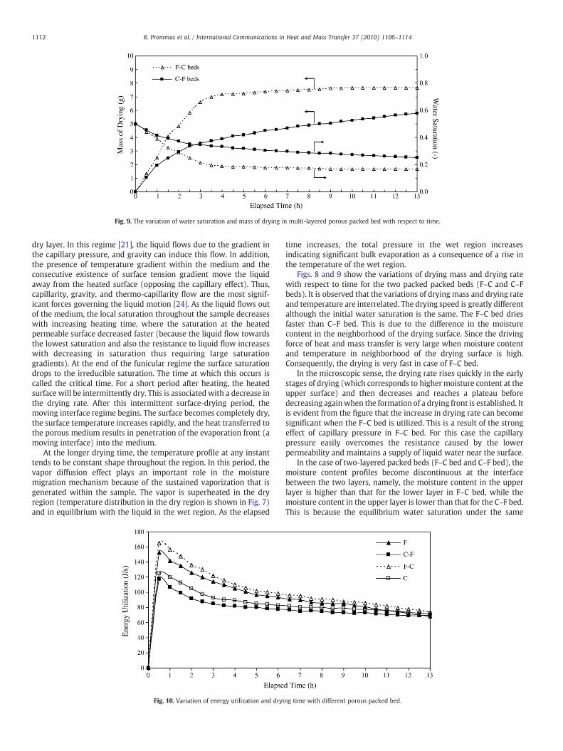
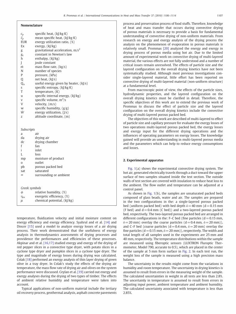
Fig. 9. The variation of water saturation and mass of drying in multi-layered porous packed bed with respect to time.
1112 R. Prommas et al. / International Communications in Heat and Mass Transfer 37 (2010) 1106–1114
dry layer. In this regime [21], the liquid flows due to the gradient inthe capillary pressure, and gravity can induce this flow. In addition,the presence of temperature gradient within the medium and theconsecutive existence of surface tension gradient move the liquidaway from the heated surface (opposing the capillary effect). Thus,capillarity, gravity, and thermo-capillarity flow are the most signif-icant forces governing the liquid motion [24]. As the liquid flows outof the medium, the local saturation throughout the sample decreaseswith increasing heating time, where the saturation at the heatedpermeable surface decreased faster (because the liquid flow towardsthe lowest saturation and also the resistance to liquid flow increaseswith decreasing in saturation thus requiring large saturationgradients). At the end of the funicular regime the surface saturationdrops to the irreducible saturation. The time at which this occurs iscalled the critical time. For a short period after heating, the heatedsurface will be intermittently dry. This is associated with a decrease inthe drying rate. After this intermittent surface-drying period, themoving interface regime begins. The surface becomes completely dry,the surface temperature increases rapidly, and the heat transferred tothe porous medium results in penetration of the evaporation front (amoving interface) into the medium.
At the longer drying time, the temperature profile at any instanttends to be constant shape throughout the region. In this period, thevapor diffusion effect plays an important role in the moisturemigration mechanism because of the sustained vaporization that isgenerated within the sample. The vapor is superheated in the dryregion (temperature distribution in the dry region is shown in Fig. 7)and in equilibrium with the liquid in the wet region. As the elapsed
Fig. 10. Variation of energy utilization and dryi
time increases, the total pressure in the wet region increasesindicating significant bulk evaporation as a consequence of a rise inthe temperature of the wet region.
Figs. 8 and 9 show the variations of drying mass and drying ratewith respect to time for the two packed packed beds (F–C and C–Fbeds). It is observed that the variations of drying mass and drying rateand temperature are interrelated. The drying speed is greatly differentalthough the initial water saturation is the same. The F–C bed driesfaster than C–F bed. This is due to the difference in the moisturecontent in the neighborhood of the drying surface. Since the drivingforce of heat and mass transfer is very large when moisture contentand temperature in neighborhood of the drying surface is high.Consequently, the drying is very fast in case of F–C bed.
In the microscopic sense, the drying rate rises quickly in the earlystages of drying (which corresponds to higher moisture content at theupper surface) and then decreases and reaches a plateau beforedecreasing againwhen the formation of a drying front is established. Itis evident from the figure that the increase in drying rate can becomesignificant when the F–C bed is utilized. This is a result of the strongeffect of capillary pressure in F–C bed. For this case the capillarypressure easily overcomes the resistance caused by the lowerpermeability and maintains a supply of liquid water near the surface.
In the case of two-layered packed beds (F–C bed and C–F bed), themoisture content profiles become discontinuous at the interfacebetween the two layers, namely, the moisture content in the upperlayer is higher than that for the lower layer in F–C bed, while themoisture content in the upper layer is lower than that for the C–F bed.This is because the equilibrium water saturation under the same
ng time with different porous packed bed.

Fig. 11. Variation of energy utilization ratio with different porous packed bed.
1113R. Prommas et al. / International Communications in Heat and Mass Transfer 37 (2010) 1106–1114
capillary pressure differs according to the particle sizes smallestparticle size corresponding to higher water saturation. Therefore, thedrying kinetics is strongly influenced by the difference in watersaturation. Continuing the drying process (Fig. 9) causes the averagewater saturation inside the F–C bed to decrease quickly in comparisonwith the C–F bed. In the case of the C–F bed, in contrast to that F–Cbed, the moisture content in the upper layer (C bed) is very low andthe dry layer is formed rapidly while the moisture content in thelower layer (F bed) remains high. This is due to the C bed (whichcorresponds to a lower capillary pressure) located above the F bedretards the upward migration of liquid water through the interfacebetween two layers and also due to the effect of gravity.
According to the experimental results from Figs. 7–9, these resultscan be used as the input parameters for analyzing the energyutilization (Eqs. (8) to (10)) and exergy efficiency (Eqs. (11) to(17)) as follows:
Fig. 10 shows the variation of energy utilization as a function ofdrying time of different configurations and drying time. The energyutilization is relatively high at the beginning of drying process due tothe high moisture content of the sample, and consequently graduallydecrease because the low moisture content of the samples at the endof the process.
Fig. 11 shows the variation of energy utilization ratio againstdrying time of F–C and C–F packed bed. Energy balance is analyzed toevaluate the energy utilization ratio. The values of energy utilizationratio in drying chamber are calculated by using Eq. (10). Whenvelocity and the temperature of hot air are kept constantly, the energyutilization ratio values are seem to be similar to energy utilization dueto energy inlet of drying process to be constant.
In order to calculate the exergetic efficiency of the drying process,exergy analysis is taken into consideration. The exergy inflow rates
Fig. 12. Variation of exergy efficiency w
were calculated by using Eq. (14) as function of the ambient and inlettemperatures. The exergy inflow during the drying of multi-layeredporous packed bed is attracted by drying layered of porous packedbed. The exergy outflows are calculated by using Eq. (15) and duringthe experiments which varied. It was observed that the exergyoutflow from the drying chamber slowly increases with an increase ofthe drying time.
The exergetic efficiency of the drying chamber increases with anincrease of drying time as shown in Fig. 12. The variation of exergyefficiency with respect to time is inversely with energy utilizationratio. This is because during drying process the available energy in thedrying chamber increases as an increase of drying time, sincemoisture content decreases with time. The effect of the multi-layeredon the drying time as well as the exergy efficiency of the dryingsystem is also presented. The exergy efficiencies in case of C–F bed arehigher than that of the F–C bed approximate 10% after 1 h of dryingtime thought the drying process. The results show that the energyutilization and exergy efficiency in Figs. 10–12 are strongly dependedof layered configuration and particle size as described in Figs. 1–9.
6. Conclusion
The experimental analysis presented in this paper describes manyimportant interactions within multi-layered porous materials duringconvective drying. The following paragraph summarizes the conclu-sions of this study:
The effects of particle sizes and layered configuration on theoverall drying kinetics are clarified. The drying rate in the F–C bed isslightly higher than that of the C–F bed. This is because the highercapillary pressure for the F–C bed results in to maintain a wetteddrying surface for a longer period of time. The F–C bed displays the
ith different porous packed bed.

1114 R. Prommas et al. / International Communications in Heat and Mass Transfer 37 (2010) 1106–1114
drying curve which differentiates it from the others. It has a shorterdrying time due to the strong effect of capillary action.
Energy and exergy of the drying process of the multi-layeredporous packed bed were analyzed. It can be concluded that energyutilization, energy utilization ratio and exergy efficiency stronglydepend on particle size and multi-layered configurations
Acknowledgment
The authors would like to express their appreciation to theCommission on Higher Education, Thailand and Thailand ResearchFund (TRF) for providing financial support for this study.
References
[1] I. Dincer, M.A. Rosen, Energy, environmental and sustainable development,Applied Energy 46 (1999) 427–440.
[2] I. Dincer, A.Z. Sahin, Incorporation of the dincer number into the moisturediffusion equation, International Communications in Heat and Mass Transfer 3(2004) 109–119.
[3] A.S. Mujumdar, An overview of innovation in industrial drying: current status andR&D needs, Transport in Porous Media 66 (2007) 3–18.
[4] I. Białobrzewski, M. Zielińska, A.S. Mujumdar, M. Markowski, Heat and masstransfer during drying of a bed of shrinking particles— simulation for carrot cubesdried in a spout-fluidized-bed drier, International Journal of Heat and MassTransfer 51 (2008) 4704–4716.
[5] N.M. Panagiotou, A.K. Stubos, G. Bamopoulos, Z.B. Maroulis Drying, kinetics of amulti-component mixture of organic solvents, Drying Technology 17 (1999)2107–2122.
[6] A.G. Yiotis, A.K. Stubos, A.G. Boudouvis, Y.C. Yortsos, A 2-D pore-network model ofthe drying of single-component liquids in porous media, Advances in WaterResources 24 (2001) 439–460.
[7] R.G. Carbonell, S. Whitaker, Dispersion in pulsed systems — II Theoreticaldevelopments for passive dispersion in porous, Chemical Engineering Science 38(1983) 1795–1802.
[8] T. Tekcin, M. Bayramogilu, Exergy loss minimization analysis of sugar productionprocess from sugar beet, Food and Bioproducts Processing 76 (1998) 149–154.
[9] M.A. Rosen, I. Dincer, On exergy and environmental impact, International Journalof Energy Research 21 (1998) 643–654.
[10] M.A. Rosen, D.S. Scott, Entropy production and exergy destruction: Part I —
hierarchy of earth's major constituencies, International Journal Hydrogen Energy28 (2003) 1307–1313.
[11] A.I. Liapis, R. Bruttini, Exergy analysis of freeze drying of pharmaceuticals in vialson trays, International Journal of Heat and Mass Transfer 51 (2008) 3854–3868.
[12] Y. Liu, Y. Zhao, X. Feng, Exergy analysis for a freeze-drying process, AppliedThermal Engineering 28 (2008) 675–690.
[13] M. Kanoglua, I. Dincer, M.A. Rosen, Understanding energy and exergy efficienciesfor improved energy management in power plants, Energy Policy 35 (2007)3967–3978.
[14] S. Syahrul, I. Dincer, F. Hamdullahpur, Thermodynamics modeling of fluidized beddrying of moist particles, International Journal of Thermal Sciences 42 (2003)691–701.
[15] I. Dincer, A.Z. Sahin, A new model for thermodynamics analysis of a dryingprocess, International Journal of Heat and Mass Transfer 47 (2004) 645–652.
[16] E.K. Akpinar, Energy and exergy ananlyses of drying of red pepper slices in aconvective type dryer, International Communication in Heat andMass Transfer 31(2004) 1165–1176.
[17] E.K. Akpinar, A. Midilli, Y. Bicer, Energy and exergy of potato drying process viacyclone type dryer, Energy Conversion and Management 46 (2005) 2530–2552.
[18] N. Colak, A. Hepbasli, Performance analysis of drying of green olive in a tray dryer,Journal of Food Engineering 80 (2007) 1188–1193.
[19] I. Ceylan, M. Aktas, H. Dogan, Energy and exergy analysis of timber dryer assistedheat pump, Applied Thermal Engineering 27 (2007) 216–222.
[20] R. Prommas, P. Rattanadecho, D. Cholaseuk, Energy and exergy analyses in dryingprocess of porous media using hot air, International Communications in Heat andMass Transfer 37 (2010) 372–378.
[21] P. Ratanadecho, K. Aoki, M. Akahori, Experimental and numerical study ofmicrowave drying in unsaturated porous material, International Communicationsin Heat and Mass Transfer 28 (2001) 605–616.
[22] A. Bejan, Advanced Engineering Thermodynamics, John Wiley and Sons, NewYork, 1998.
[23] J.E. Ahern, The Exergy Method of Energy Systems Analysis, John Wiley, New York,1980.
[24] M. Kaviany, J. Rogers, Funicular and evaporative-front regimes in convectivedrying of granular beds, International Journal of Heat andMass Transfer 35 (1992)469–480.