Embed Size (px)
Citation preview
IDSS IDD Revision C November 20, 2013
International Docking System Standard (IDSS) Interface Definition Document (IDD) Revision C
November 20, 2013

IDSS IDD Revision C November 20, 2013
This page intentionally left blank.
IDSS IDD Revision C November 20, 2013
iii
Concurrence

IDSS IDD Revision C November 20, 2013
iv
This page intentionally left blank.
IDSS IDD Revision C November 20, 2013
v
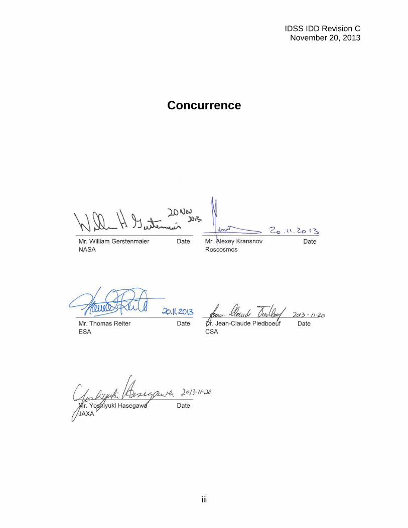
Revision Log
Document Revision
Effective Date
Description
IDSS IDD 09/21/2010 Initial release
Revision A 04/27/2011
Revised, rearranged, and added text to nearly all sections of document. Revised & renumbered figures. Added requirements on mechanical soft capture, soft capture sensors, HCS seals, hook stiffness, separation system, electrical bonding, environments, and materials. Added Docking Performance section, and Appendix A.
Revision B 11/15/2012 Document Hard Capture System parameter values, figure updates, separation system force addition, editorial correction and updates.
Revision C 11/20/2013
Document the narrow ring Soft Capture System (SCS) geometric parameters and update applicable figures. Added Appendix B on Magnetic Soft Capture.

IDSS IDD Revision C November 20, 2013
vi
This page intentionally left blank.
IDSS IDD Revision C November 20, 2013
vii
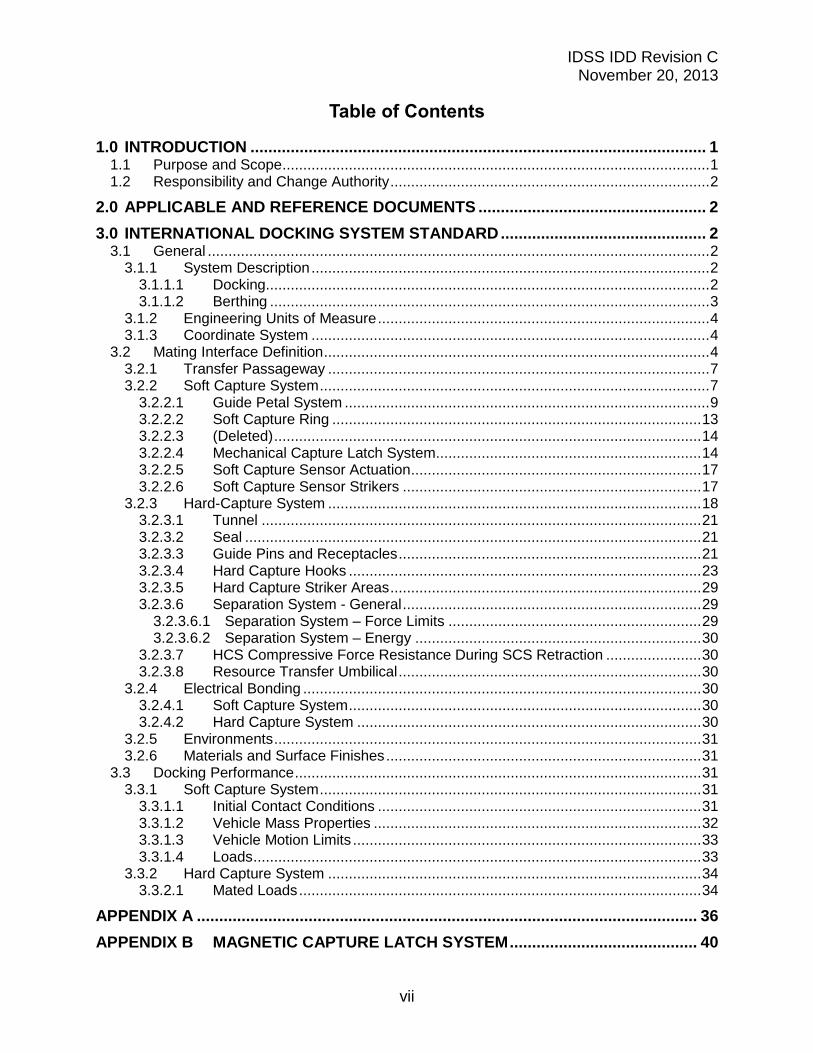
Table of Contents
1.0 INTRODUCTION ...................................................................................................... 1 1.1 Purpose and Scope ....................................................................................................... 1 1.2 Responsibility and Change Authority ............................................................................. 2
2.0 APPLICABLE AND REFERENCE DOCUMENTS ................................................... 2
3.0 INTERNATIONAL DOCKING SYSTEM STANDARD .............................................. 2 3.1 General ......................................................................................................................... 2
3.1.1 System Description ................................................................................................ 2 3.1.1.1 Docking........................................................................................................... 2 3.1.1.2 Berthing .......................................................................................................... 3
3.1.2 Engineering Units of Measure ................................................................................ 4 3.1.3 Coordinate System ................................................................................................ 4
3.2 Mating Interface Definition ............................................................................................. 4 3.2.1 Transfer Passageway ............................................................................................ 7 3.2.2 Soft Capture System .............................................................................................. 7
3.2.2.1 Guide Petal System ........................................................................................ 9 3.2.2.2 Soft Capture Ring ......................................................................................... 13 3.2.2.3 (Deleted) ....................................................................................................... 14 3.2.2.4 Mechanical Capture Latch System ................................................................ 14 3.2.2.5 Soft Capture Sensor Actuation ...................................................................... 17 3.2.2.6 Soft Capture Sensor Strikers ........................................................................ 17
3.2.3 Hard-Capture System .......................................................................................... 18 3.2.3.1 Tunnel .......................................................................................................... 21 3.2.3.2 Seal .............................................................................................................. 21 3.2.3.3 Guide Pins and Receptacles ......................................................................... 21 3.2.3.4 Hard Capture Hooks ..................................................................................... 23 3.2.3.5 Hard Capture Striker Areas ........................................................................... 29 3.2.3.6 Separation System - General ........................................................................ 29
3.2.3.6.1 Separation System – Force Limits ............................................................. 29 3.2.3.6.2 Separation System – Energy ..................................................................... 30
3.2.3.7 HCS Compressive Force Resistance During SCS Retraction ....................... 30 3.2.3.8 Resource Transfer Umbilical ......................................................................... 30
3.2.4 Electrical Bonding ................................................................................................ 30 3.2.4.1 Soft Capture System ..................................................................................... 30 3.2.4.2 Hard Capture System ................................................................................... 30
3.2.5 Environments ....................................................................................................... 31 3.2.6 Materials and Surface Finishes ............................................................................ 31
3.3 Docking Performance .................................................................................................. 31 3.3.1 Soft Capture System ............................................................................................ 31
3.3.1.1 Initial Contact Conditions .............................................................................. 31 3.3.1.2 Vehicle Mass Properties ............................................................................... 32 3.3.1.3 Vehicle Motion Limits .................................................................................... 33 3.3.1.4 Loads ............................................................................................................ 33
3.3.2 Hard Capture System .......................................................................................... 34 3.3.2.1 Mated Loads ................................................................................................. 34
APPENDIX A ................................................................................................................ 36
APPENDIX B MAGNETIC CAPTURE LATCH SYSTEM .......................................... 40
IDSS IDD Revision C November 20, 2013
viii
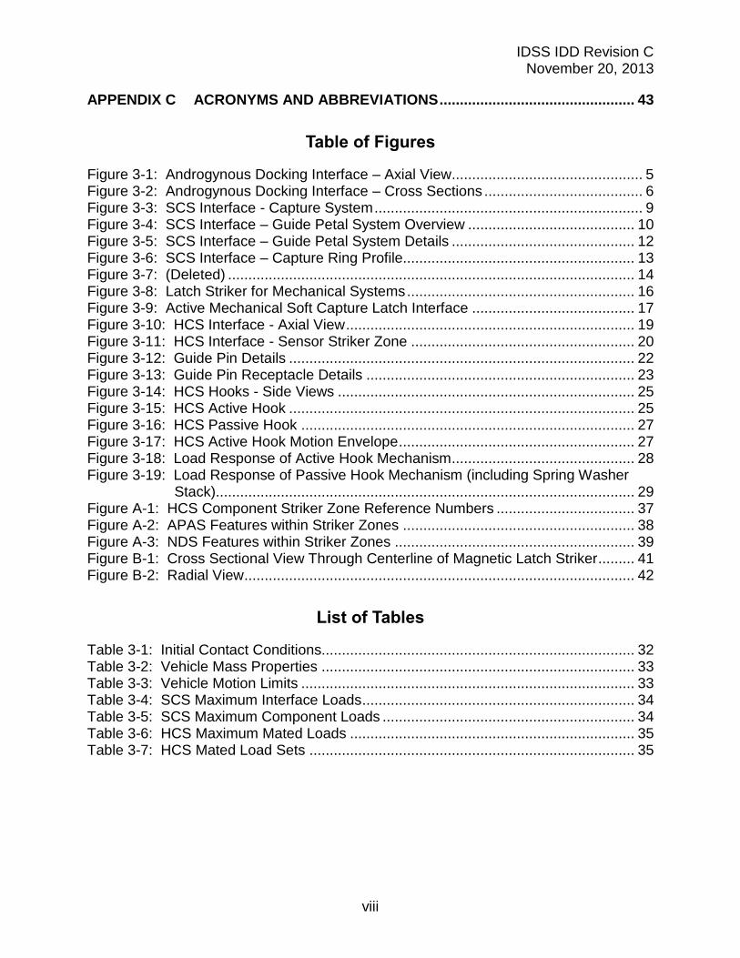
APPENDIX C ACRONYMS AND ABBREVIATIONS ................................................ 43
Table of Figures
Figure 3-1: Androgynous Docking Interface – Axial View ............................................... 5 Figure 3-2: Androgynous Docking Interface – Cross Sections ....................................... 6 Figure 3-3: SCS Interface - Capture System .................................................................. 9 Figure 3-4: SCS Interface – Guide Petal System Overview ......................................... 10 Figure 3-5: SCS Interface – Guide Petal System Details ............................................. 12
Figure 3-6: SCS Interface – Capture Ring Profile......................................................... 13 Figure 3-7: (Deleted) .................................................................................................... 14 Figure 3-8: Latch Striker for Mechanical Systems ........................................................ 16 Figure 3-9: Active Mechanical Soft Capture Latch Interface ........................................ 17
Figure 3-10: HCS Interface - Axial View ....................................................................... 19 Figure 3-11: HCS Interface - Sensor Striker Zone ....................................................... 20
Figure 3-12: Guide Pin Details ..................................................................................... 22 Figure 3-13: Guide Pin Receptacle Details .................................................................. 23 Figure 3-14: HCS Hooks - Side Views ......................................................................... 25
Figure 3-15: HCS Active Hook ..................................................................................... 25 Figure 3-16: HCS Passive Hook .................................................................................. 27
Figure 3-17: HCS Active Hook Motion Envelope .......................................................... 27 Figure 3-18: Load Response of Active Hook Mechanism ............................................. 28 Figure 3-19: Load Response of Passive Hook Mechanism (including Spring Washer
Stack) ....................................................................................................... 29 Figure A-1: HCS Component Striker Zone Reference Numbers .................................. 37
Figure A-2: APAS Features within Striker Zones ......................................................... 38 Figure A-3: NDS Features within Striker Zones ........................................................... 39
Figure B-1: Cross Sectional View Through Centerline of Magnetic Latch Striker ......... 41 Figure B-2: Radial View ................................................................................................ 42
List of Tables
Table 3-1: Initial Contact Conditions............................................................................. 32 Table 3-2: Vehicle Mass Properties ............................................................................. 33 Table 3-3: Vehicle Motion Limits .................................................................................. 33 Table 3-4: SCS Maximum Interface Loads ................................................................... 34 Table 3-5: SCS Maximum Component Loads .............................................................. 34
Table 3-6: HCS Maximum Mated Loads ...................................................................... 35 Table 3-7: HCS Mated Load Sets ................................................................................ 35
IDSS IDD Revision C November 20, 2013
1
1.0 INTRODUCTION
This International Docking System Standard (IDSS) Interface Definition Document (IDD) is the result of a collaboration by the International Space Station membership to establish a standard docking interface to enable on-orbit crew rescue operations and joint collaborative endeavors utilizing different spacecraft.
This IDSS IDD details the physical geometric mating interface and design loads requirements. The physical geometric interface requirements must be strictly followed to ensure physical spacecraft mating compatibility. This includes both defined components and areas that are void of components. The IDD also identifies common design parameters as identified in section 3.0, e.g., docking initial conditions and vehicle mass properties. This information represents a recommended set of design values enveloping a broad set of design reference missions and conditions, which if accommodated in the docking system design, increases the probability of successful docking between different spacecraft.
This IDD does not address operational procedures or off-nominal situations, nor does it dictate implementation or design features behind the mating interface. It is the responsibility of the spacecraft developer to perform all hardware verification and validation, and to perform final docking analyses to ensure the needed docking performance and to develop the final certification loads for their application.
While there are many other critical requirements needed in the development of a docking system such as fault tolerance, reliability, and environments (e.g. vibration, etc.), it is not the intent of the IDSS IDD to mandate all of these requirements; these requirements must be addressed as part of the specific developer’s unique program, spacecraft and mission needs. This approach allows designers the flexibility to design and build docking mechanisms to their unique program needs and requirements.
1.1 Purpose and Scope
The purpose of the IDSS IDD is to provide basic common design parameters to allow developers to independently design compatible docking systems. The IDSS is intended for uses ranging from crewed to autonomous space vehicles, and from Low Earth Orbit (LEO) to deep-space exploration missions.
This document defines docking system interface definitions supporting the following missions:
A. International Space Station (ISS) visitation B. Exploration missions beyond LEO C. Crew rescue D. International cooperative missions
IDSS IDD Revision C November 20, 2013
2
Vehicles using this interface may include light vehicles in the range of 5-8 tonnes, and medium vehicles in the range of 8-25 tonnes. These vehicles will dock to each other, to large space complexes in the range of 100-375 tonnes, and to large earth departure stages in the range of 33-170 tonnes. The figures and tables in this document depict the features of the docking interface that are standardized. Some docking features (e.g. sensors, separation systems) are not standardized and are left to the discretion of docking system designers, though they must follow the designated striker zone requirements. Resource umbilicals are not yet standardized and are not yet defined in this standard.
1.2 Responsibility and Change Authority
Any proposed changes to the IDSS by the participating partners of this agreement shall be brought forward to the IDSS committee for review.
Configuration control of this document is the responsibility of the International Space Station (ISS) Multilateral Control Board (MCB), which is comprised of the international partner members of the ISS. The National Aeronautics and Space Administration (NASA) will maintain the IDSS IDD under ISS Configuration Management, until an appropriate International Standards Body is identified and mutually agreed.
2.0 APPLICABLE AND REFERENCE DOCUMENTS
None.
3.0 INTERNATIONAL DOCKING SYSTEM STANDARD
3.1 General
The following subsections describe the system interfaces for the IDSS.
3.1.1 System Description
3.1.1.1 Docking
The IDSS IDD defines a 2-stage approach to docking. The first stage establishes the initial capture of the docking vehicles, and is performed by the Soft Capture System (SCS). During the capture phase, the active docking mechanism’s SCS aligns with and latches to the passive docking mechanism, then stabilizes the newly joined spacecraft relative to each other. The soft capture system then pulls the docking spacecraft together in order to initiate the second stage of docking, performed by the Hard Capture System (HCS). The HCS performs structural latching and sealing at the docking
IDSS IDD Revision C November 20, 2013
3
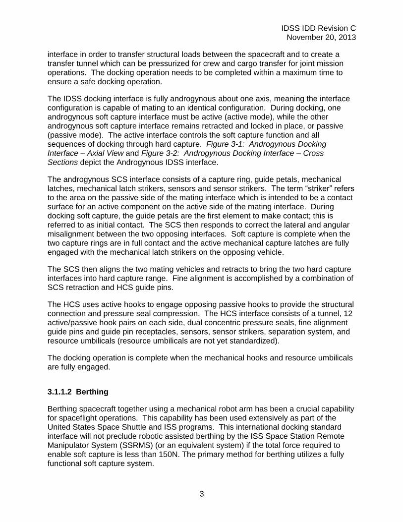
interface in order to transfer structural loads between the spacecraft and to create a transfer tunnel which can be pressurized for crew and cargo transfer for joint mission operations. The docking operation needs to be completed within a maximum time to ensure a safe docking operation.
The IDSS docking interface is fully androgynous about one axis, meaning the interface configuration is capable of mating to an identical configuration. During docking, one androgynous soft capture interface must be active (active mode), while the other androgynous soft capture interface remains retracted and locked in place, or passive (passive mode). The active interface controls the soft capture function and all sequences of docking through hard capture. Figure 3-1: Androgynous Docking Interface – Axial View and Figure 3-2: Androgynous Docking Interface – Cross Sections depict the Androgynous IDSS interface.
The androgynous SCS interface consists of a capture ring, guide petals, mechanical latches, mechanical latch strikers, sensors and sensor strikers. The term “striker” refers to the area on the passive side of the mating interface which is intended to be a contact surface for an active component on the active side of the mating interface. During docking soft capture, the guide petals are the first element to make contact; this is referred to as initial contact. The SCS then responds to correct the lateral and angular misalignment between the two opposing interfaces. Soft capture is complete when the two capture rings are in full contact and the active mechanical capture latches are fully engaged with the mechanical latch strikers on the opposing vehicle.
The SCS then aligns the two mating vehicles and retracts to bring the two hard capture interfaces into hard capture range. Fine alignment is accomplished by a combination of SCS retraction and HCS guide pins.
The HCS uses active hooks to engage opposing passive hooks to provide the structural connection and pressure seal compression. The HCS interface consists of a tunnel, 12 active/passive hook pairs on each side, dual concentric pressure seals, fine alignment guide pins and guide pin receptacles, sensors, sensor strikers, separation system, and resource umbilicals (resource umbilicals are not yet standardized).
The docking operation is complete when the mechanical hooks and resource umbilicals are fully engaged.
3.1.1.2 Berthing
Berthing spacecraft together using a mechanical robot arm has been a crucial capability for spaceflight operations. This capability has been used extensively as part of the United States Space Shuttle and ISS programs. This international docking standard interface will not preclude robotic assisted berthing by the ISS Space Station Remote Manipulator System (SSRMS) (or an equivalent system) if the total force required to enable soft capture is less than 150N. The primary method for berthing utilizes a fully functional soft capture system.
IDSS IDD Revision C November 20, 2013
4
3.1.2 Engineering Units of Measure
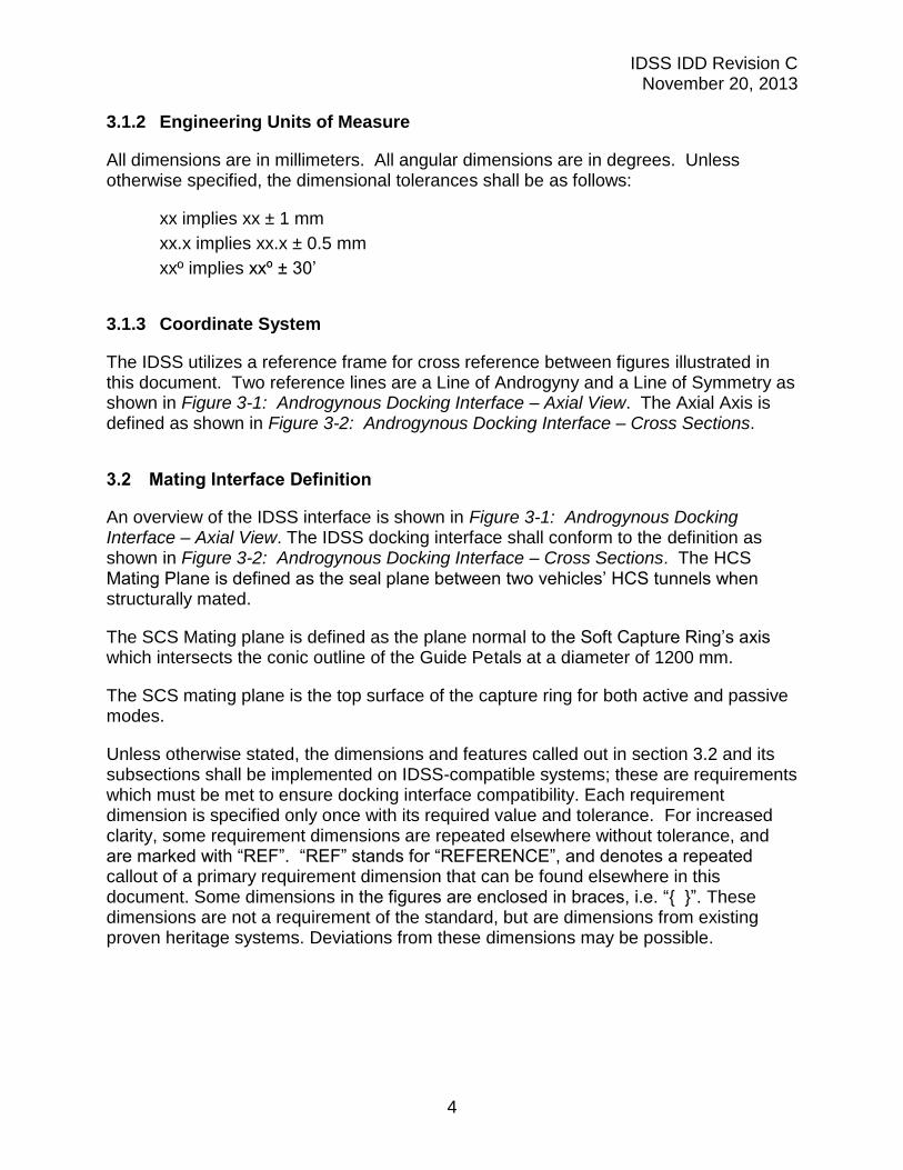
All dimensions are in millimeters. All angular dimensions are in degrees. Unless otherwise specified, the dimensional tolerances shall be as follows:
xx implies xx ± 1 mm
xx.x implies xx.x ± 0.5 mm
xxº implies xxº ± 30’
3.1.3 Coordinate System
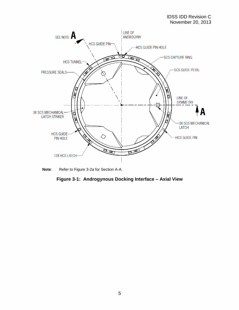
The IDSS utilizes a reference frame for cross reference between figures illustrated in this document. Two reference lines are a Line of Androgyny and a Line of Symmetry as shown in Figure 3-1: Androgynous Docking Interface – Axial View. The Axial Axis is defined as shown in Figure 3-2: Androgynous Docking Interface – Cross Sections.
3.2 Mating Interface Definition
An overview of the IDSS interface is shown in Figure 3-1: Androgynous Docking Interface – Axial View. The IDSS docking interface shall conform to the definition as shown in Figure 3-2: Androgynous Docking Interface – Cross Sections. The HCS Mating Plane is defined as the seal plane between two vehicles’ HCS tunnels when structurally mated.
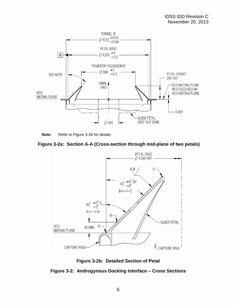
The SCS Mating plane is defined as the plane normal to the Soft Capture Ring’s axis which intersects the conic outline of the Guide Petals at a diameter of 1200 mm.
The SCS mating plane is the top surface of the capture ring for both active and passive modes.
Unless otherwise stated, the dimensions and features called out in section 3.2 and its subsections shall be implemented on IDSS-compatible systems; these are requirements which must be met to ensure docking interface compatibility. Each requirement dimension is specified only once with its required value and tolerance. For increased clarity, some requirement dimensions are repeated elsewhere without tolerance, and are marked with “REF”. “REF” stands for “REFERENCE”, and denotes a repeated callout of a primary requirement dimension that can be found elsewhere in this document. Some dimensions in the figures are enclosed in braces, i.e. “{ }”. These dimensions are not a requirement of the standard, but are dimensions from existing proven heritage systems. Deviations from these dimensions may be possible.
IDSS IDD Revision C November 20, 2013
5
Note: Refer to Figure 3-2a for Section A-A.
Figure 3-1: Androgynous Docking Interface – Axial View
IDSS IDD Revision C November 20, 2013
6
Note: Refer to Figure 3-2b for details
Figure 3-2a: Section A-A (Cross-section through mid-plane of two petals)
Figure 3-2b: Detailed Section of Petal
Figure 3-2: Androgynous Docking Interface – Cross Sections
IDSS IDD Revision C November 20, 2013
7
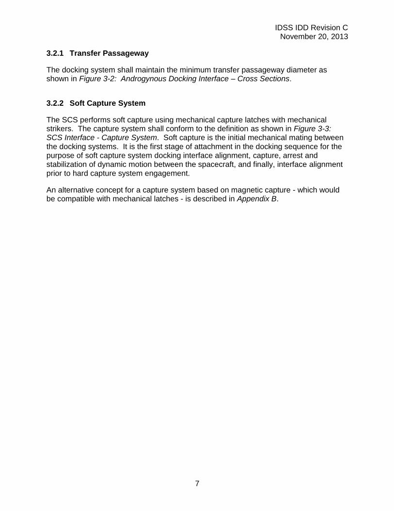
3.2.1 Transfer Passageway
The docking system shall maintain the minimum transfer passageway diameter as shown in Figure 3-2: Androgynous Docking Interface – Cross Sections.
3.2.2 Soft Capture System
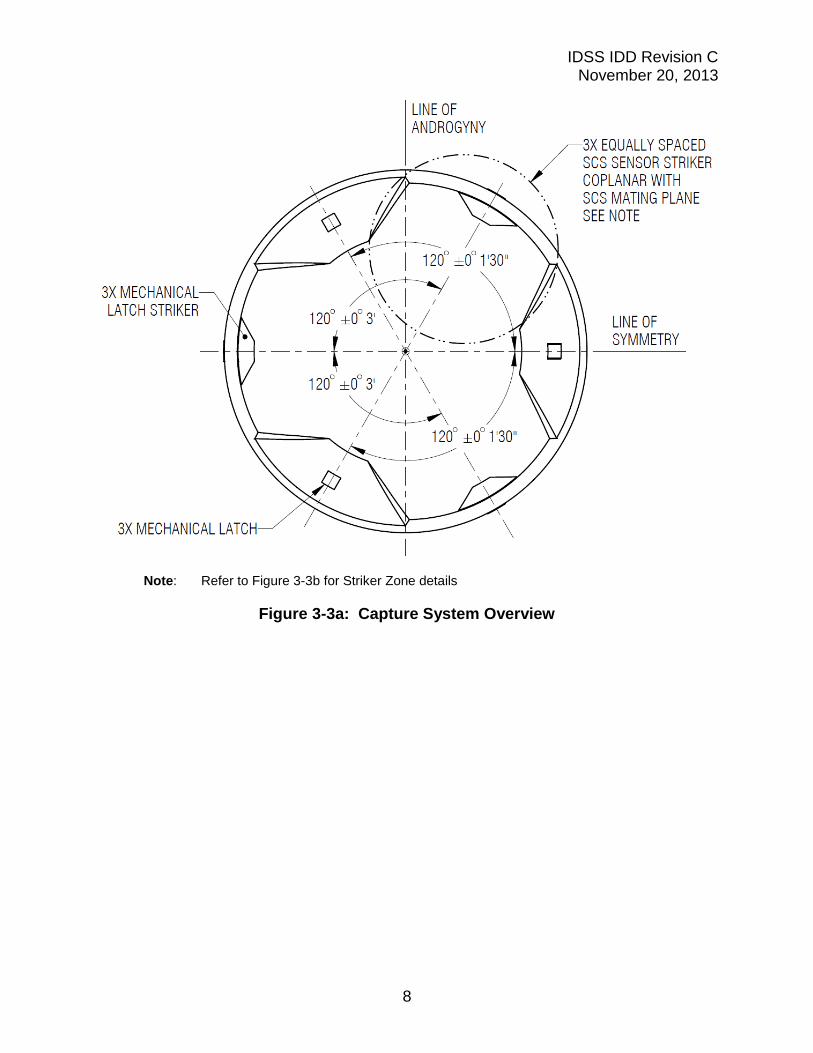
The SCS performs soft capture using mechanical capture latches with mechanical strikers. The capture system shall conform to the definition as shown in Figure 3-3: SCS Interface - Capture System. Soft capture is the initial mechanical mating between the docking systems. It is the first stage of attachment in the docking sequence for the purpose of soft capture system docking interface alignment, capture, arrest and stabilization of dynamic motion between the spacecraft, and finally, interface alignment prior to hard capture system engagement.
An alternative concept for a capture system based on magnetic capture - which would be compatible with mechanical latches - is described in Appendix B.
IDSS IDD Revision C November 20, 2013
8
Note: Refer to Figure 3-3b for Striker Zone details
Figure 3-3a: Capture System Overview
IDSS IDD Revision C November 20, 2013
9
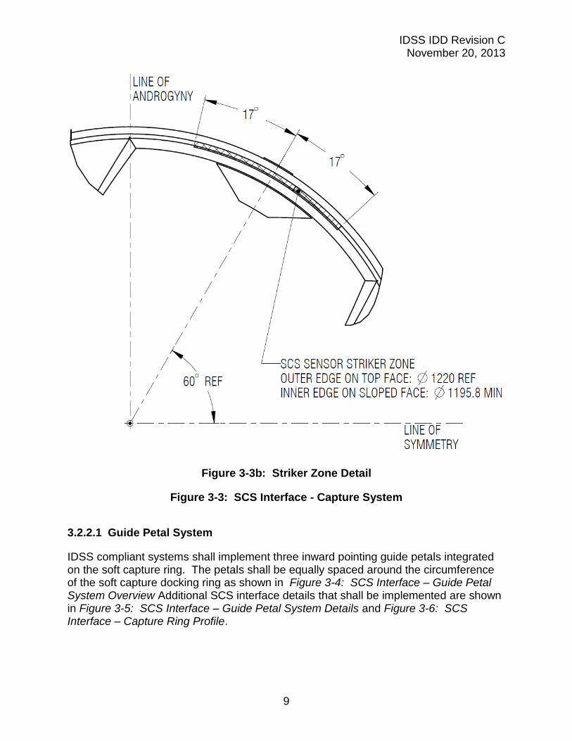
Figure 3-3b: Striker Zone Detail
Figure 3-3: SCS Interface - Capture System
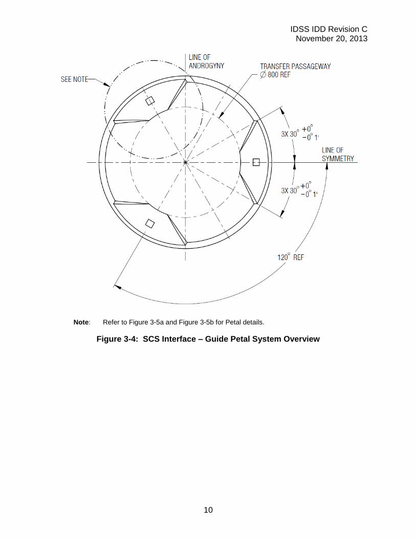
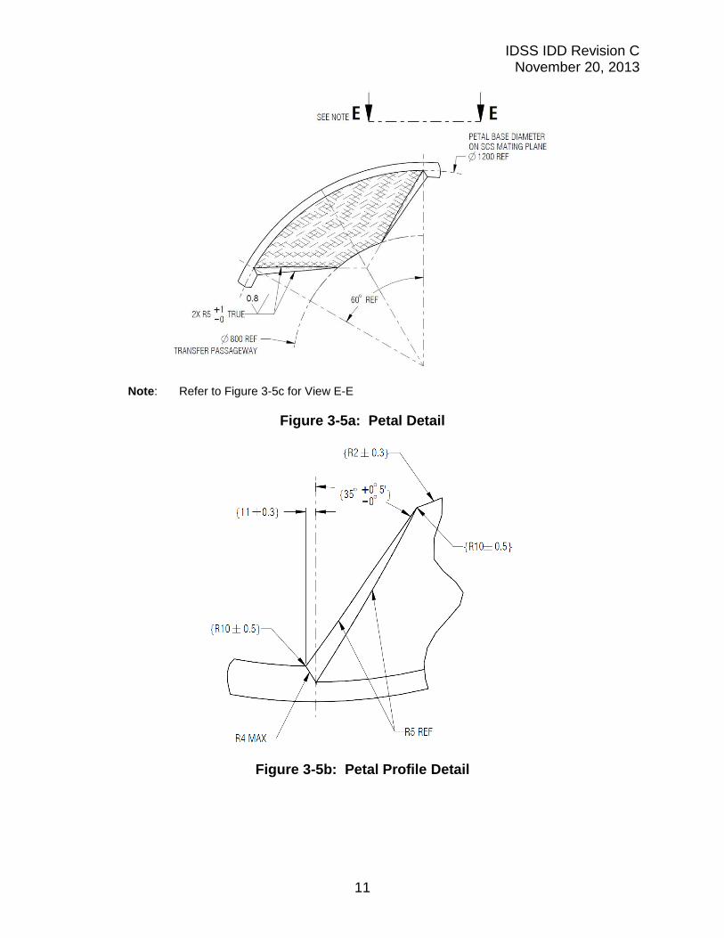
3.2.2.1 Guide Petal System
IDSS compliant systems shall implement three inward pointing guide petals integrated on the soft capture ring. The petals shall be equally spaced around the circumference of the soft capture docking ring as shown in Figure 3-4: SCS Interface – Guide Petal System Overview Additional SCS interface details that shall be implemented are shown in Figure 3-5: SCS Interface – Guide Petal System Details and Figure 3-6: SCS Interface – Capture Ring Profile.
IDSS IDD Revision C November 20, 2013
10
Note: Refer to Figure 3-5a and Figure 3-5b for Petal details.
Figure 3-4: SCS Interface – Guide Petal System Overview
IDSS IDD Revision C November 20, 2013
11
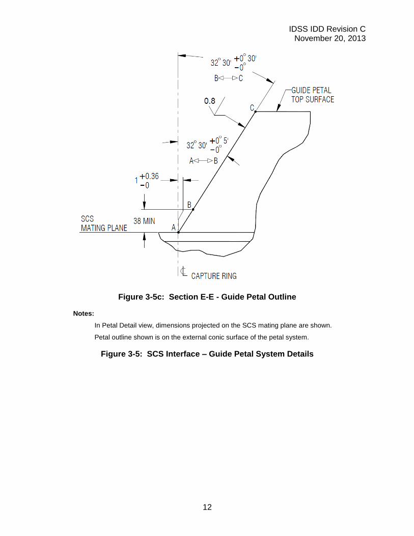
Note: Refer to Figure 3-5c for View E-E
Figure 3-5a: Petal Detail
Figure 3-5b: Petal Profile Detail
IDSS IDD Revision C November 20, 2013
12
Figure 3-5c: Section E-E - Guide Petal Outline
Notes:
In Petal Detail view, dimensions projected on the SCS mating plane are shown.
Petal outline shown is on the external conic surface of the petal system.
Figure 3-5: SCS Interface – Guide Petal System Details
IDSS IDD Revision C November 20, 2013
13
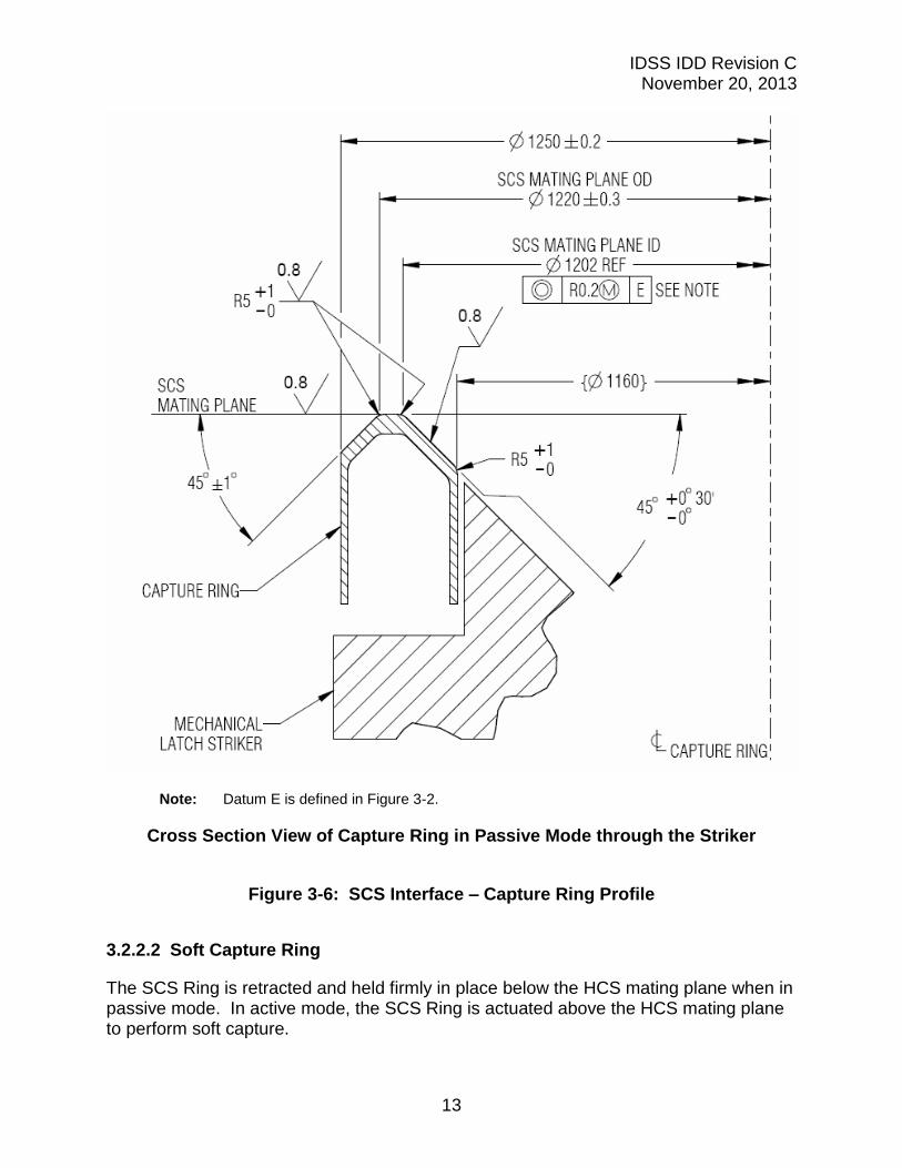
Note: Datum E is defined in Figure 3-2.
Cross Section View of Capture Ring in Passive Mode through the Striker
Figure 3-6: SCS Interface – Capture Ring Profile
3.2.2.2 Soft Capture Ring
The SCS Ring is retracted and held firmly in place below the HCS mating plane when in passive mode. In active mode, the SCS Ring is actuated above the HCS mating plane to perform soft capture.
IDSS IDD Revision C November 20, 2013
14
3.2.2.3 (Deleted)
Figure 3-7: (Deleted)
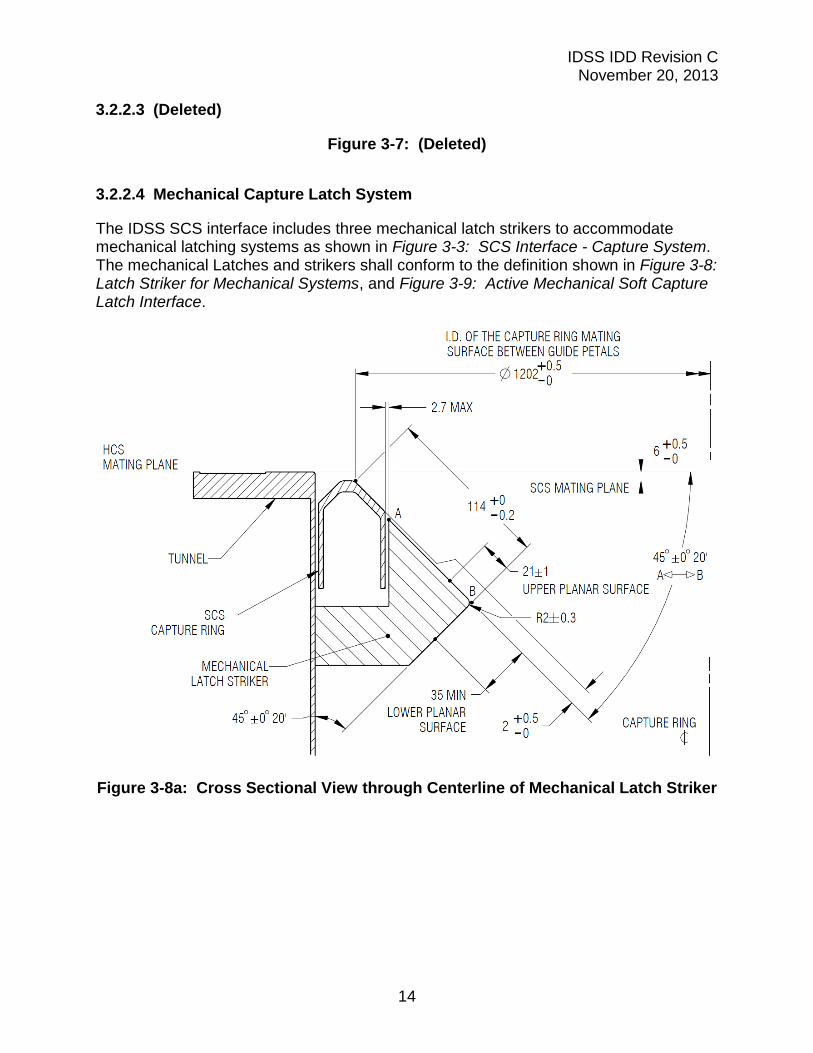
3.2.2.4 Mechanical Capture Latch System
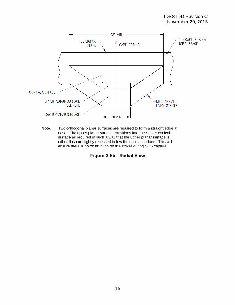
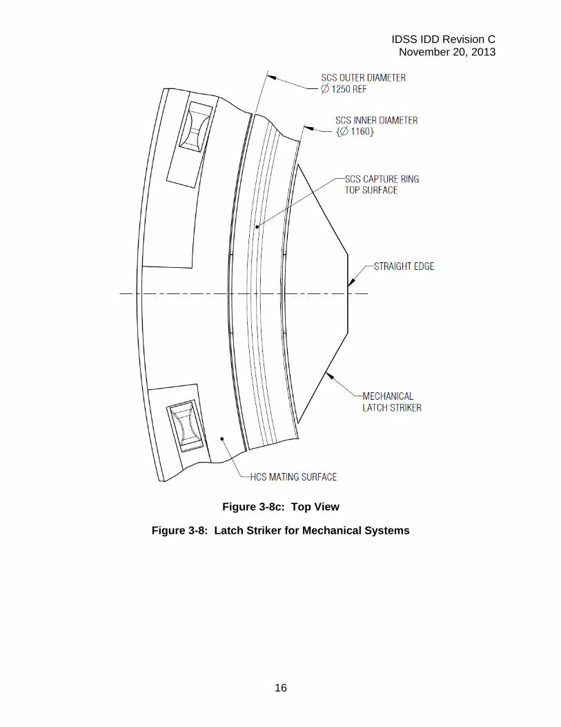
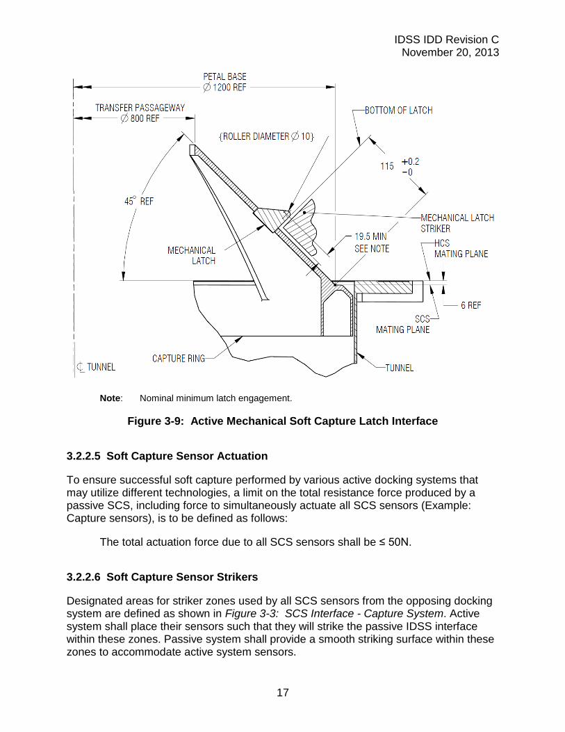
The IDSS SCS interface includes three mechanical latch strikers to accommodate mechanical latching systems as shown in Figure 3-3: SCS Interface - Capture System. The mechanical Latches and strikers shall conform to the definition shown in Figure 3-8: Latch Striker for Mechanical Systems, and Figure 3-9: Active Mechanical Soft Capture Latch Interface.
Figure 3-8a: Cross Sectional View through Centerline of Mechanical Latch Striker
IDSS IDD Revision C November 20, 2013
15
Note: Two orthogonal planar surfaces are required to form a straight edge at nose. The upper planar surface transitions into the Striker conical surface as required in such a way that the upper planar surface is either flush or slightly recessed below the conical surface. This will ensure there is no obstruction on the striker during SCS capture.
Figure 3-8b: Radial View
IDSS IDD Revision C November 20, 2013
16
Figure 3-8c: Top View
Figure 3-8: Latch Striker for Mechanical Systems
IDSS IDD Revision C November 20, 2013
17
Note: Nominal minimum latch engagement.
Figure 3-9: Active Mechanical Soft Capture Latch Interface
3.2.2.5 Soft Capture Sensor Actuation
To ensure successful soft capture performed by various active docking systems that may utilize different technologies, a limit on the total resistance force produced by a passive SCS, including force to simultaneously actuate all SCS sensors (Example: Capture sensors), is to be defined as follows:
The total actuation force due to all SCS sensors shall be ≤ 50N.
3.2.2.6 Soft Capture Sensor Strikers
Designated areas for striker zones used by all SCS sensors from the opposing docking system are defined as shown in Figure 3-3: SCS Interface - Capture System. Active system shall place their sensors such that they will strike the passive IDSS interface within these zones. Passive system shall provide a smooth striking surface within these zones to accommodate active system sensors.

IDSS IDD Revision C November 20, 2013
18
3.2.3 Hard-Capture System
The Hard Capture System (HCS) performs the final structural mating between the two vehicles, establishing a connection capable of withstanding atmospheric pressure combined with the loads from planned mated operations of the two spacecraft.
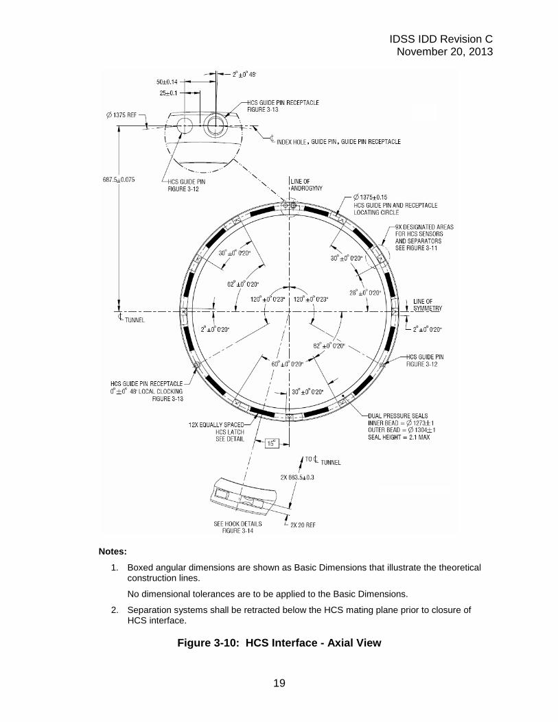
The HCS interface shall conform to the definition as shown in Figure 3-10: HCS Interface - Axial View and Figure 3-11: HCS Interface - Sensor Striker Zone. HCS components that are not critical for transferring mated loads or maintaining pressurization are intentionally omitted from these figures for clarity. Designated striker regions are identified for participants to configure peripheral hardware (e.g. separation system and sensors).
IDSS IDD Revision C November 20, 2013
19
Notes:
1. Boxed angular dimensions are shown as Basic Dimensions that illustrate the theoretical construction lines.
No dimensional tolerances are to be applied to the Basic Dimensions.
2. Separation systems shall be retracted below the HCS mating plane prior to closure of HCS interface.
Figure 3-10: HCS Interface - Axial View
IDSS IDD Revision C November 20, 2013
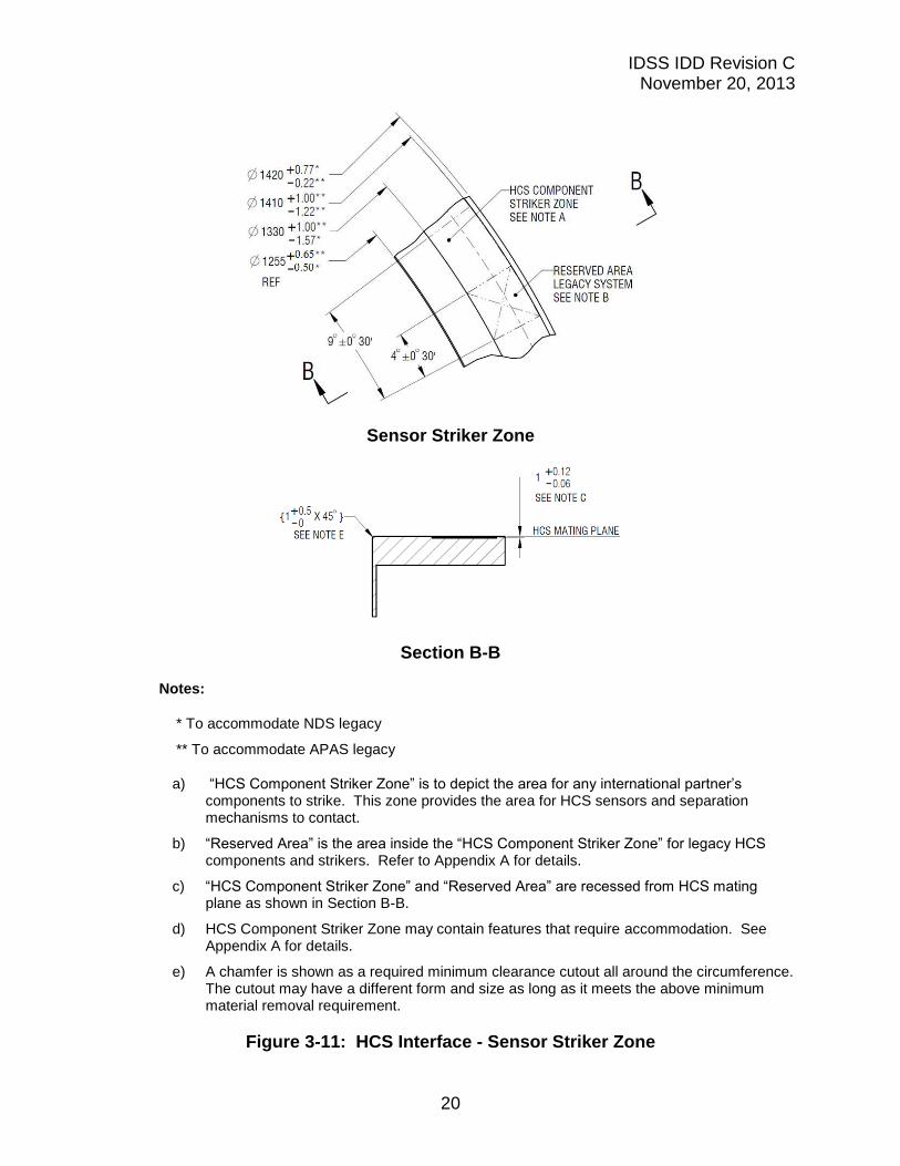
20
Sensor Striker Zone
Section B-B
Notes:
* To accommodate NDS legacy
** To accommodate APAS legacy
a) “HCS Component Striker Zone” is to depict the area for any international partner’s components to strike. This zone provides the area for HCS sensors and separation mechanisms to contact.
b) “Reserved Area” is the area inside the “HCS Component Striker Zone” for legacy HCS components and strikers. Refer to Appendix A for details.
c) “HCS Component Striker Zone” and “Reserved Area” are recessed from HCS mating plane as shown in Section B-B.
d) HCS Component Striker Zone may contain features that require accommodation. See Appendix A for details.
e) A chamfer is shown as a required minimum clearance cutout all around the circumference. The cutout may have a different form and size as long as it meets the above minimum material removal requirement.
Figure 3-11: HCS Interface - Sensor Striker Zone
IDSS IDD Revision C November 20, 2013
21
3.2.3.1 Tunnel
The tunnel is the main housing of the docking system that includes the interface flange for structural mating.
3.2.3.2 Seal
The HCS shall implement two concentric pressure seals that accommodate seal-on-seal mating. For seal diametral dimensions, refer to Figure 3-10: HCS Interface - Axial View. The pressure seals are located internally with respect to the tangential hook location. Seal parameters shall be as defined below. Also see Table 3-6: HCS Maximum Mated Loads for seal closure (compression) force.
Total seal adhesion force for both concentric seals ≤ 900 N
Seal protrusion height in a free state above the HCS mating plane ≤ 2.1 mm
“Seal adhesion force” is defined as the force that is required to pull the docking pressure seals apart after they have been pressed together.
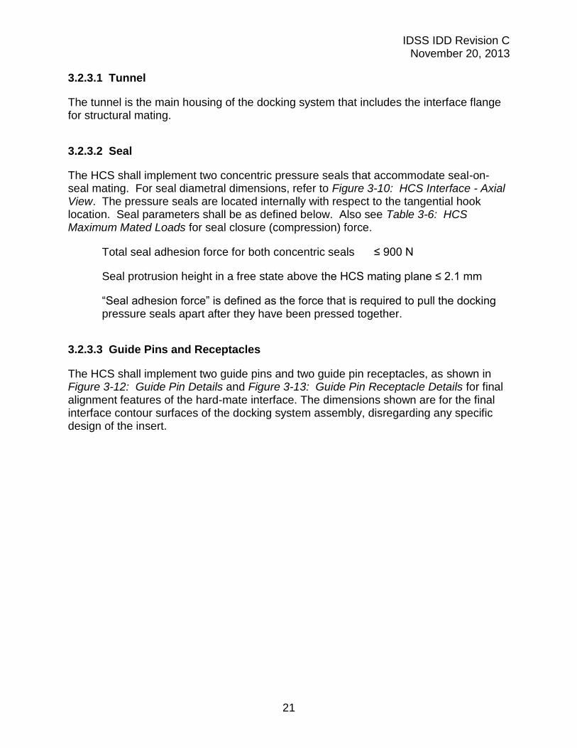
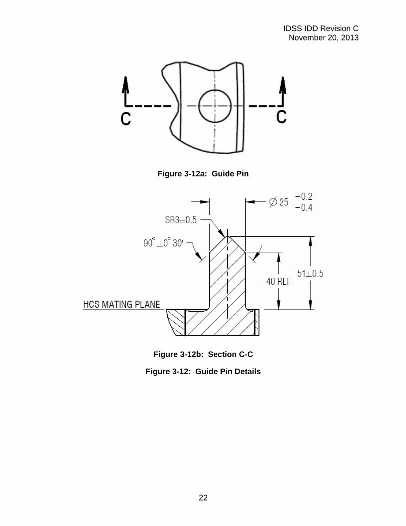
3.2.3.3 Guide Pins and Receptacles
The HCS shall implement two guide pins and two guide pin receptacles, as shown in Figure 3-12: Guide Pin Details and Figure 3-13: Guide Pin Receptacle Details for final alignment features of the hard-mate interface. The dimensions shown are for the final interface contour surfaces of the docking system assembly, disregarding any specific design of the insert.
IDSS IDD Revision C November 20, 2013
22
Figure 3-12a: Guide Pin
Figure 3-12b: Section C-C
Figure 3-12: Guide Pin Details
IDSS IDD Revision C November 20, 2013
23
Figure 3-13a: Guide Pin Receptacle
*Note: As the Guide Pin Receptacle is located in a recessed area, this dimension depicts the distance from the HCS Mating Plane to the start of the hole chamfer.
Figure 3-13b: Section D-D
Figure 3-13: Guide Pin Receptacle Details
3.2.3.4 Hard Capture Hooks
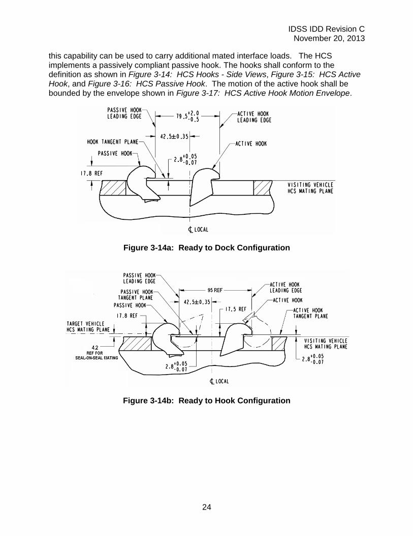
The HCS shall incorporate 12 pairs of active and passive hooks, located as shown in Figure 3-10: HCS Interface - Axial View. To carry nominal loads, 12 active hooks on one docking system shall engage 12 passive hooks on an opposing docking system interface. On a fully androgynous system, the 12 active hooks on each side of the interface may be engaged with the 12 passive hooks on the opposing interface for a total of 24 active hook engagements. Although engaging 24 hooks is not a requirement,
IDSS IDD Revision C November 20, 2013
24
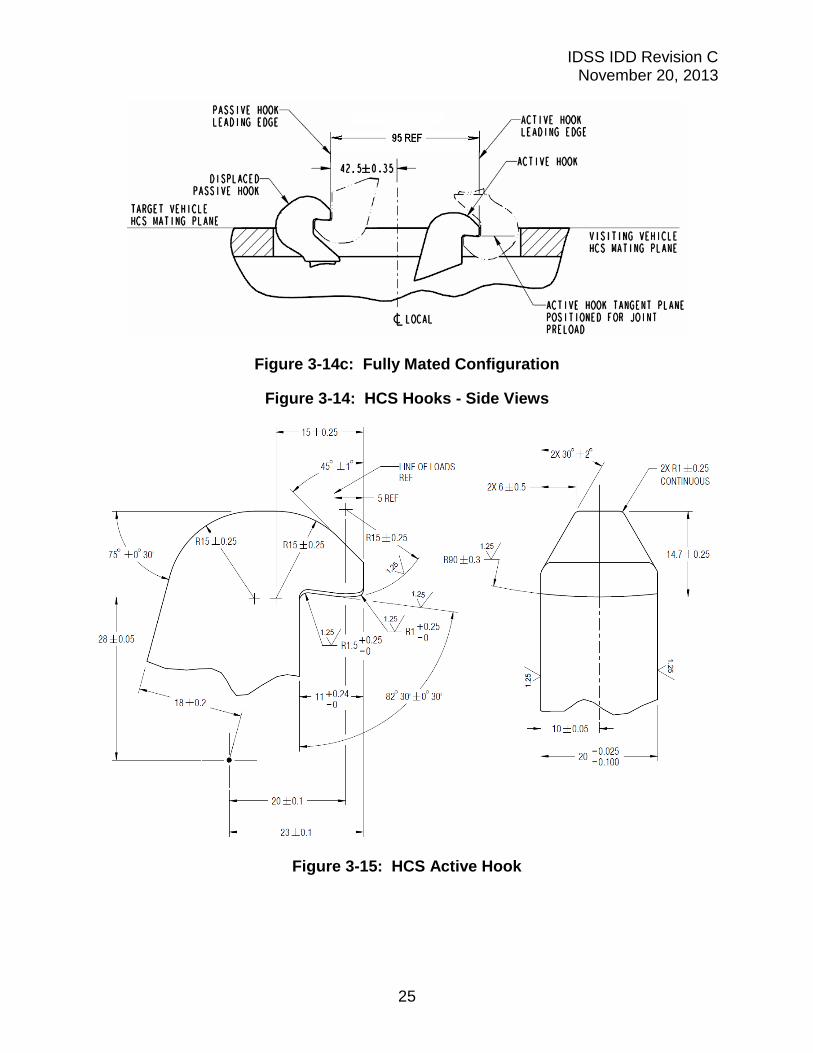
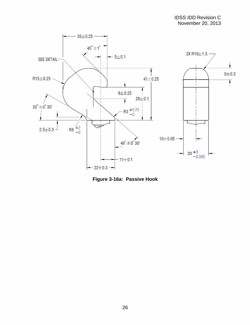
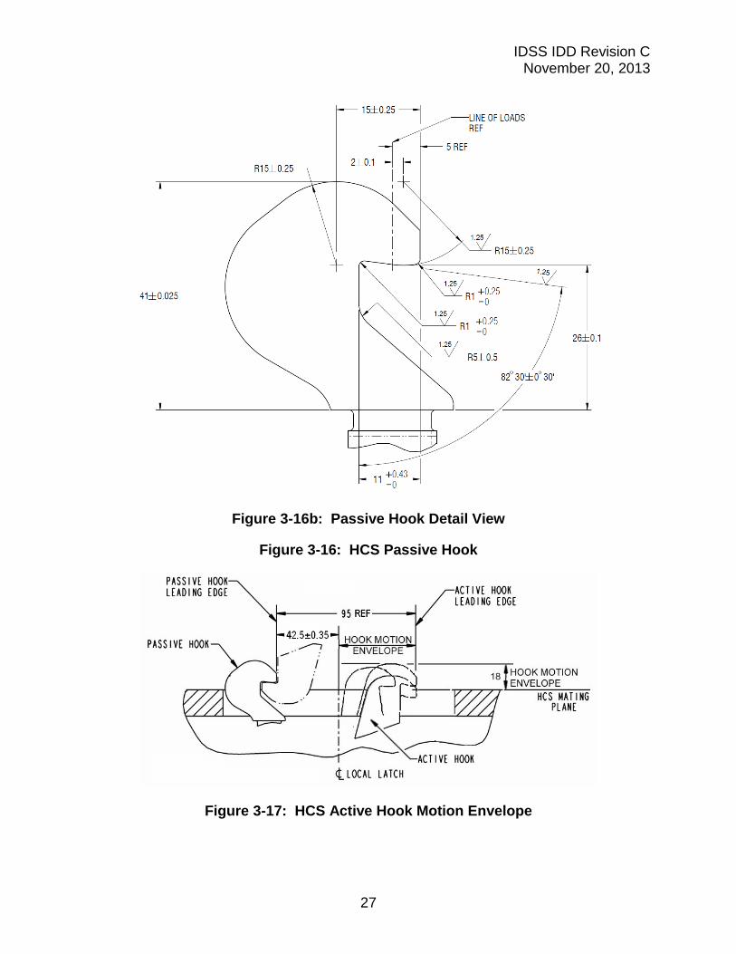
this capability can be used to carry additional mated interface loads. The HCS implements a passively compliant passive hook. The hooks shall conform to the definition as shown in Figure 3-14: HCS Hooks - Side Views, Figure 3-15: HCS Active Hook, and Figure 3-16: HCS Passive Hook. The motion of the active hook shall be bounded by the envelope shown in Figure 3-17: HCS Active Hook Motion Envelope.
Figure 3-14a: Ready to Dock Configuration
Figure 3-14b: Ready to Hook Configuration
IDSS IDD Revision C November 20, 2013
25
Figure 3-14c: Fully Mated Configuration
Figure 3-14: HCS Hooks - Side Views
Figure 3-15: HCS Active Hook
IDSS IDD Revision C November 20, 2013
26
Figure 3-16a: Passive Hook
IDSS IDD Revision C November 20, 2013
27
Figure 3-16b: Passive Hook Detail View
Figure 3-16: HCS Passive Hook
Figure 3-17: HCS Active Hook Motion Envelope
IDSS IDD Revision C November 20, 2013
28
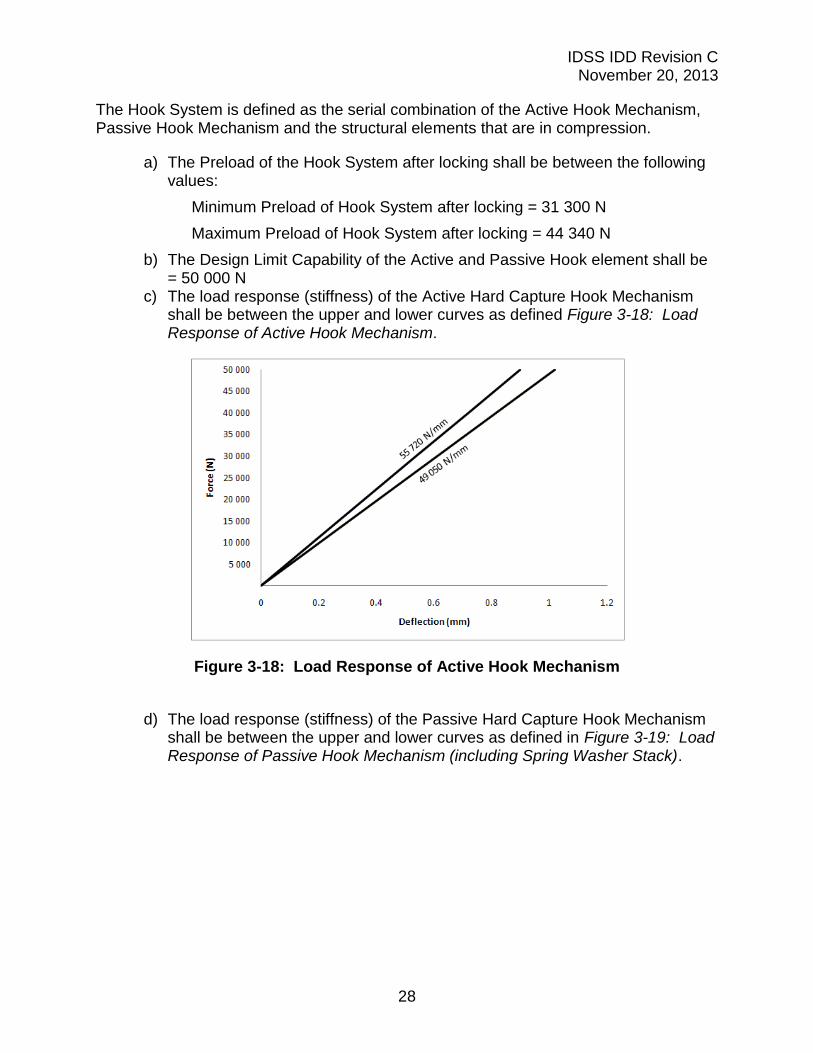
The Hook System is defined as the serial combination of the Active Hook Mechanism, Passive Hook Mechanism and the structural elements that are in compression.
a) The Preload of the Hook System after locking shall be between the following values:
Minimum Preload of Hook System after locking = 31 300 N
Maximum Preload of Hook System after locking = 44 340 N
b) The Design Limit Capability of the Active and Passive Hook element shall be = 50 000 N
c) The load response (stiffness) of the Active Hard Capture Hook Mechanism shall be between the upper and lower curves as defined Figure 3-18: Load Response of Active Hook Mechanism.
Figure 3-18: Load Response of Active Hook Mechanism
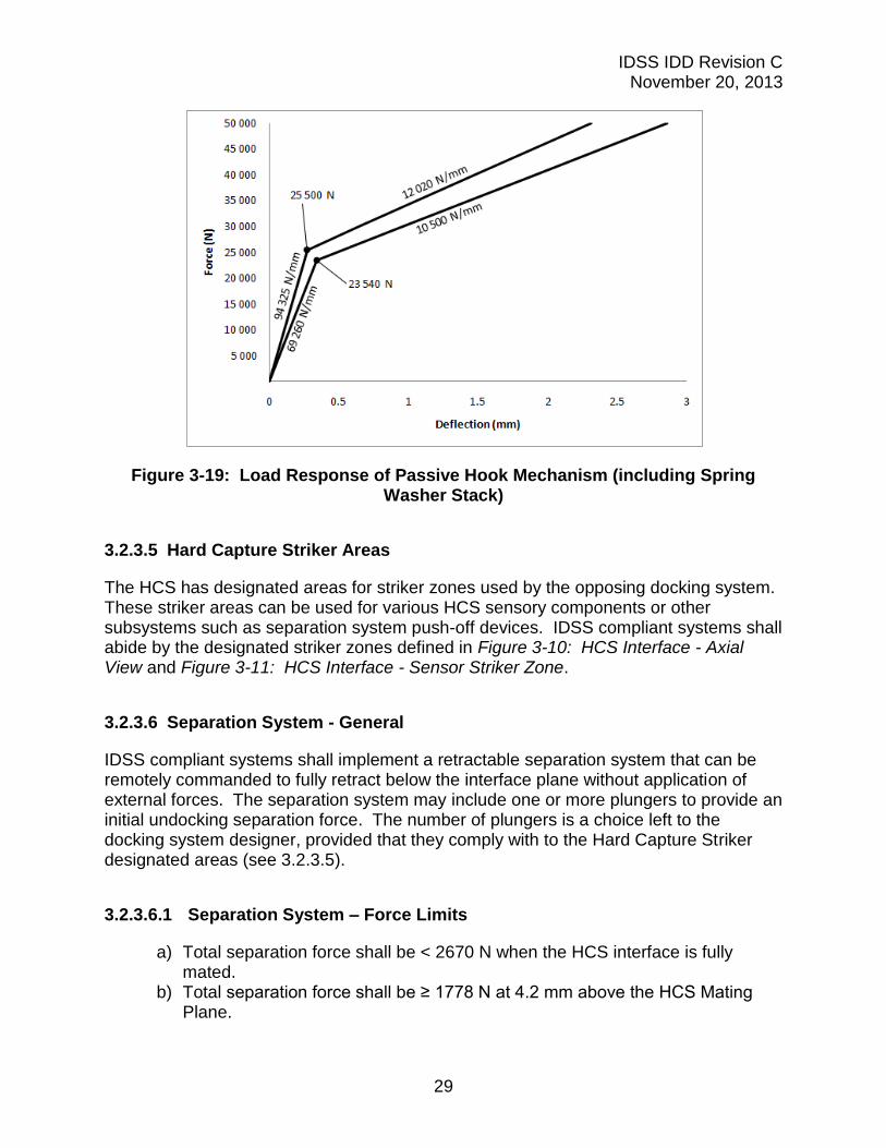
d) The load response (stiffness) of the Passive Hard Capture Hook Mechanism
shall be between the upper and lower curves as defined in Figure 3-19: Load Response of Passive Hook Mechanism (including Spring Washer Stack).
IDSS IDD Revision C November 20, 2013
29
Figure 3-19: Load Response of Passive Hook Mechanism (including Spring Washer Stack)
3.2.3.5 Hard Capture Striker Areas
The HCS has designated areas for striker zones used by the opposing docking system. These striker areas can be used for various HCS sensory components or other subsystems such as separation system push-off devices. IDSS compliant systems shall abide by the designated striker zones defined in Figure 3-10: HCS Interface - Axial View and Figure 3-11: HCS Interface - Sensor Striker Zone.
3.2.3.6 Separation System - General
IDSS compliant systems shall implement a retractable separation system that can be remotely commanded to fully retract below the interface plane without application of external forces. The separation system may include one or more plungers to provide an initial undocking separation force. The number of plungers is a choice left to the docking system designer, provided that they comply with to the Hard Capture Striker designated areas (see 3.2.3.5).
3.2.3.6.1 Separation System – Force Limits
a) Total separation force shall be < 2670 N when the HCS interface is fully mated.
b) Total separation force shall be ≥ 1778 N at 4.2 mm above the HCS Mating Plane.
IDSS IDD Revision C November 20, 2013
30
3.2.3.6.2 Separation System – Energy
Total energy available from the separation system shall be between 39.2 N-m and 47.5 N-m when the HCS interface is fully mated.
3.2.3.7 HCS Compressive Force Resistance During SCS Retraction
During the SCS retraction for hard mate, sensors on the mating HCS mechanisms, such as “Ready-to-Hook” or “Undocking-Complete” indicators, will be compressed. A limit on the total resistance force produced by all sensors on the passive HCS system during SCS retraction is to be defined as follows:
The total resistance force contributed by all HCS sensors on the passive side shall be ≤ 85 N at a separation of ≥ 4.2 mm between the HCS Mating Planes.
3.2.3.8 Resource Transfer Umbilical
The resource transfer umbilicals are not yet standardized in the IDSS. Umbilical connectors transfer resources between the mated vehicles. These resources may include power, data, and ground safety wire, water source and water return, fuel, tank pressurization, and oxidizer.
3.2.4 Electrical Bonding
3.2.4.1 Soft Capture System
IDSS compliant systems shall establish bond paths to mitigate electrical hazards on the integrated subsystem interfaces.
IDSS compliant mechanisms protect against electrostatic discharge through the soft capture system. The bond path may be through any metal to metal contact provisions for this purpose. The requirement is from initial contact to hard capture during the docking operation.
Bonding resistance for the SCS after soft capture shall be 1 ohm or less TBC.
3.2.4.2 Hard Capture System
IDSS compliant mechanisms are to be protected against RF emissions. The bond path is through metal to metal contact on the seal interface between two IDSS compliant HCS mechanisms.
Bonding resistance for the HCS after latching shall be 2.5 milliohms or less.
IDSS IDD Revision C November 20, 2013
31
3.2.5 Environments
Materials used in the construction of the docking interface shall allow proper mating while experiencing the following conditions:
a) Temperature difference between the two mating interfaces of up to 55°C b) External pressure environment < 1.0 x 10⁻⁴ Pa
3.2.6 Materials and Surface Finishes
In general, the interface features defined herein, except for the pressure seals, should have stiffness and hardness comparable to that of metal alloys commonly used in aerospace vehicle primary structures, and which do not significantly impede relative motion. Interface surfaces which slide against each other to assist in docking interface alignment should incorporate a surface coating or finish that has low friction characteristics. The resultant coefficient of friction between two mating systems is an integrated performance characteristic which affects soft capture success.
Specific material selection for the pressure seals will be at the designer’s discretion.
3.3 Docking Performance
In addition to the physical geometric interface requirements, a set of common design parameters enveloping the reference missions and conditions is provided. For the SCS, this set includes interface loads, vehicle mass properties, and initial contact conditions. For the HCS, this set includes mated loads. Of these common design parameters, only the loads have been defined as requirements. The other common design parameters, if accommodated in the docking system design, increase the probability of successful docking between different spacecraft.
3.3.1 Soft Capture System
The SCS docking performance is defined by the mechanism's ability to capture and attenuate. During the capture phase, the mechanism is contending with the spacecraft misalignment to achieve capture. During the attenuation phase, the mechanism is limiting the relative motion and limiting the loads.
3.3.1.1 Initial Contact Conditions
Initial contact conditions are the instantaneous relative states of the active docking interface with respect to the passive docking interface at docking interface first contact (first physical touch). They are used to define the lateral and angular misalignment, and translational and angular velocity errors when compared to perfect interface alignment and zero relative velocity at the docking interfaces. To increase the probability of
IDSS IDD Revision C November 20, 2013
32
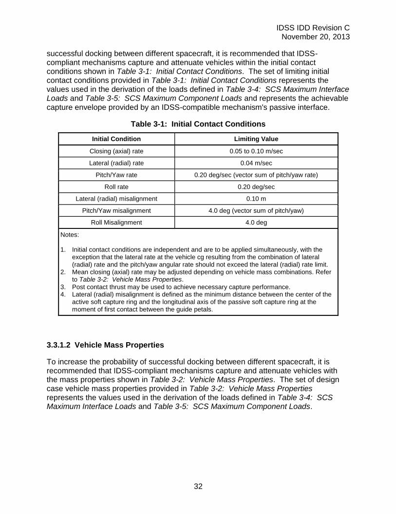
successful docking between different spacecraft, it is recommended that IDSS-compliant mechanisms capture and attenuate vehicles within the initial contact conditions shown in Table 3-1: Initial Contact Conditions. The set of limiting initial contact conditions provided in Table 3-1: Initial Contact Conditions represents the values used in the derivation of the loads defined in Table 3-4: SCS Maximum Interface Loads and Table 3-5: SCS Maximum Component Loads and represents the achievable capture envelope provided by an IDSS-compatible mechanism's passive interface.
Table 3-1: Initial Contact Conditions
Initial Condition Limiting Value
Closing (axial) rate 0.05 to 0.10 m/sec
Lateral (radial) rate 0.04 m/sec
Pitch/Yaw rate 0.20 deg/sec (vector sum of pitch/yaw rate)
Roll rate 0.20 deg/sec
Lateral (radial) misalignment 0.10 m
Pitch/Yaw misalignment 4.0 deg (vector sum of pitch/yaw)
Roll Misalignment 4.0 deg
Notes: 1. Initial contact conditions are independent and are to be applied simultaneously, with the
exception that the lateral rate at the vehicle cg resulting from the combination of lateral (radial) rate and the pitch/yaw angular rate should not exceed the lateral (radial) rate limit.
2. Mean closing (axial) rate may be adjusted depending on vehicle mass combinations. Refer to Table 3-2: Vehicle Mass Properties.
3. Post contact thrust may be used to achieve necessary capture performance. 4. Lateral (radial) misalignment is defined as the minimum distance between the center of the
active soft capture ring and the longitudinal axis of the passive soft capture ring at the moment of first contact between the guide petals.
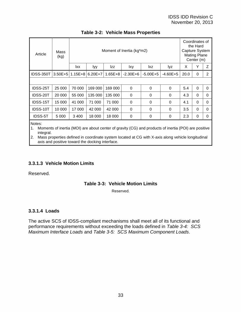
3.3.1.2 Vehicle Mass Properties
To increase the probability of successful docking between different spacecraft, it is recommended that IDSS-compliant mechanisms capture and attenuate vehicles with the mass properties shown in Table 3-2: Vehicle Mass Properties. The set of design case vehicle mass properties provided in Table 3-2: Vehicle Mass Properties represents the values used in the derivation of the loads defined in Table 3-4: SCS Maximum Interface Loads and Table 3-5: SCS Maximum Component Loads.
IDSS IDD Revision C November 20, 2013
33
Table 3-2: Vehicle Mass Properties
Article Mass (kg)
Moment of Inertia (kg*m2)
Coordinates of the Hard
Capture System Mating Plane Center (m)
lxx lyy lzz Ixy lxz lyz X Y Z
IDSS-350T 3.50E+5 1.15E+8 6.20E+7 1.65E+8 -2.30E+6 -5.00E+5 -4.60E+5 20.0 0 2
IDSS-25T 25 000 70 000 169 000 169 000 0 0 0 5.4 0 0
IDSS-20T 20 000 55 000 135 000 135 000 0 0 0 4.3 0 0
IDSS-15T 15 000 41 000 71 000 71 000 0 0 0 4.1 0 0
IDSS-10T 10 000 17 000 42 000 42 000 0 0 0 3.5 0 0
IDSS-5T 5 000 3 400 18 000 18 000 0 0 0 2.3 0 0
Notes: 1. Moments of inertia (MOI) are about center of gravity (CG) and products of inertia (POI) are positive
integral. 2. Mass properties defined in coordinate system located at CG with X-axis along vehicle longitudinal
axis and positive toward the docking interface.
3.3.1.3 Vehicle Motion Limits
Reserved.
Table 3-3: Vehicle Motion Limits
Reserved.
3.3.1.4 Loads
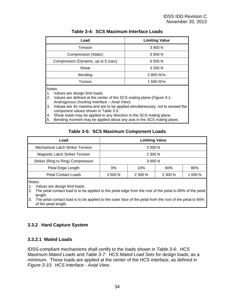
The active SCS of IDSS-compliant mechanisms shall meet all of its functional and performance requirements without exceeding the loads defined in Table 3-4: SCS Maximum Interface Loads and Table 3-5: SCS Maximum Component Loads.
IDSS IDD Revision C November 20, 2013
34
Table 3-4: SCS Maximum Interface Loads
Load Limiting Value
Tension 3 900 N
Compression (Static) 3 500 N
Compression (Dynamic, up to 0.1sec) 6 500 N
Shear 3 200 N
Bending 2 800 N*m
Torsion 1 500 N*m
Notes: 1. Values are design limit loads. 2. Values are defined at the center of the SCS mating plane (Figure 3-1:
Androgynous Docking Interface – Axial View). 3. Values are 3σ maxima and are to be applied simultaneously, not to exceed the
component values shown in Table 3-5. 4. Shear loads may be applied in any direction in the SCS mating plane. 5. Bending moment may be applied about any axis in the SCS mating plane.
Table 3-5: SCS Maximum Component Loads
Load Limiting Value
Mechanical Latch Striker Tension 3 000 N
Magnetic Latch Striker Tension 2 300 N
Striker (Ring to Ring) Compression 3 000 N
Petal Edge Length 0% 10% 60% 80%
Petal Contact Loads 3 500 N 2 300 N 2 300 N 1 000 N
Notes: 1. Values are design limit loads. 2. The petal contact load is to be applied to the petal edge from the root of the petal to 80% of the petal
length. 3. The petal contact load is to be applied to the outer face of the petal from the root of the petal to 60%
of the petal length.
3.3.2 Hard Capture System
3.3.2.1 Mated Loads
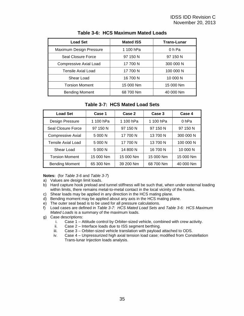
IDSS-compliant mechanisms shall certify to the loads shown in Table 3-6: HCS Maximum Mated Loads and Table 3-7: HCS Mated Load Sets for design loads, as a minimum. These loads are applied at the center of the HCS interface, as defined in Figure 3-10: HCS Interface - Axial View.
IDSS IDD Revision C November 20, 2013
35
Table 3-6: HCS Maximum Mated Loads
Load Set Mated ISS Trans-Lunar
Maximum Design Pressure 1 100 hPa 0 h Pa
Seal Closure Force 97 150 N 97 150 N
Compressive Axial Load 17 700 N 300 000 N
Tensile Axial Load 17 700 N 100 000 N
Shear Load 16 700 N 10 000 N
Torsion Moment 15 000 Nm 15 000 Nm
Bending Moment 68 700 Nm 40 000 Nm
Table 3-7: HCS Mated Load Sets
Load Set Case 1 Case 2 Case 3 Case 4
Design Pressure 1 100 hPa 1 100 hPa 1 100 hPa 0 hPa
Seal Closure Force 97 150 N 97 150 N 97 150 N 97 150 N
Compressive Axial 5 000 N 17 700 N 13 700 N 300 000 N
Tensile Axial Load 5 000 N 17 700 N 13 700 N 100 000 N
Shear Load 5 000 N 14 800 N 16 700 N 10 000 N
Torsion Moment 15 000 Nm 15 000 Nm 15 000 Nm 15 000 Nm
Bending Moment 65 300 Nm 39 200 Nm 68 700 Nm 40 000 Nm
Notes: (for Table 3-6 and Table 3-7) a) Values are design limit loads. b) Hard capture hook preload and tunnel stiffness will be such that, when under external loading
within limits, there remains metal-to-metal contact in the local vicinity of the hooks. c) Shear loads may be applied in any direction in the HCS mating plane. d) Bending moment may be applied about any axis in the HCS mating plane. e) The outer seal bead is to be used for all pressure calculations. f) Load cases are defined in Table 3-7: HCS Mated Load Sets and Table 3-6: HCS Maximum
Mated Loads is a summary of the maximum loads. g) Case descriptions:
i. Case 1 – Attitude control by Orbiter-sized vehicle, combined with crew activity. ii. Case 2 – Interface loads due to ISS segment berthing. iii. Case 3 – Orbiter-sized vehicle translation with payload attached to ODS. iv. Case 4 – Unpressurized high axial tension load case; modified from Constellation
Trans-lunar Injection loads analysis.
IDSS IDD Revision C November 20, 2013
36
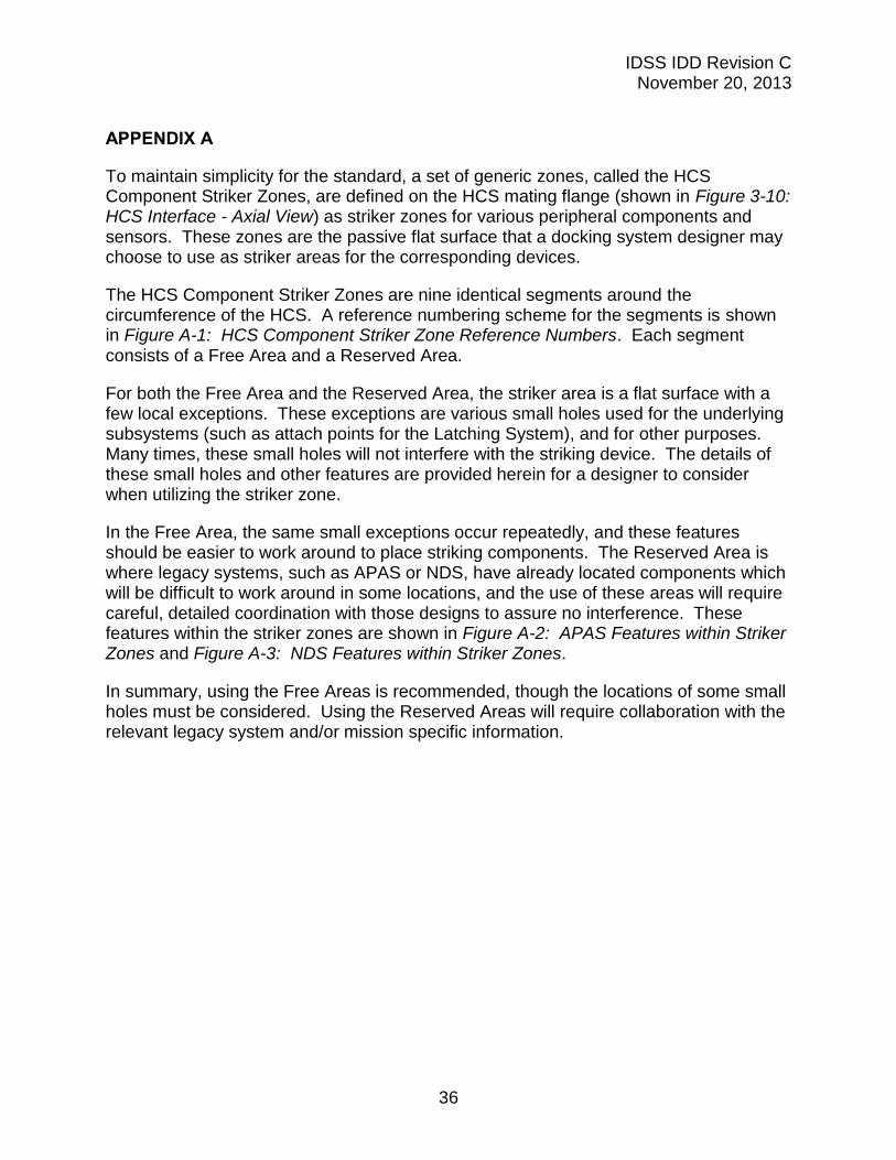
APPENDIX A
To maintain simplicity for the standard, a set of generic zones, called the HCS Component Striker Zones, are defined on the HCS mating flange (shown in Figure 3-10: HCS Interface - Axial View) as striker zones for various peripheral components and sensors. These zones are the passive flat surface that a docking system designer may choose to use as striker areas for the corresponding devices.
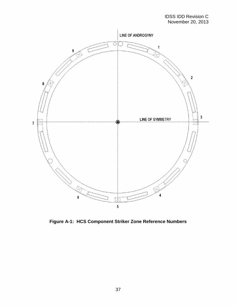
The HCS Component Striker Zones are nine identical segments around the circumference of the HCS. A reference numbering scheme for the segments is shown in Figure A-1: HCS Component Striker Zone Reference Numbers. Each segment consists of a Free Area and a Reserved Area.
For both the Free Area and the Reserved Area, the striker area is a flat surface with a few local exceptions. These exceptions are various small holes used for the underlying subsystems (such as attach points for the Latching System), and for other purposes. Many times, these small holes will not interfere with the striking device. The details of these small holes and other features are provided herein for a designer to consider when utilizing the striker zone.
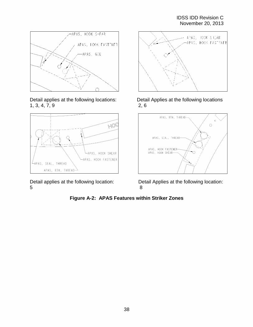
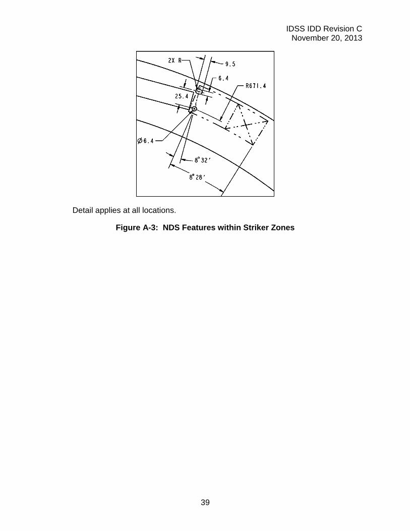
In the Free Area, the same small exceptions occur repeatedly, and these features should be easier to work around to place striking components. The Reserved Area is where legacy systems, such as APAS or NDS, have already located components which will be difficult to work around in some locations, and the use of these areas will require careful, detailed coordination with those designs to assure no interference. These features within the striker zones are shown in Figure A-2: APAS Features within Striker Zones and Figure A-3: NDS Features within Striker Zones.
In summary, using the Free Areas is recommended, though the locations of some small holes must be considered. Using the Reserved Areas will require collaboration with the relevant legacy system and/or mission specific information.
IDSS IDD Revision C November 20, 2013
37
Figure A-1: HCS Component Striker Zone Reference Numbers
IDSS IDD Revision C November 20, 2013
38
Detail applies at the following locations: Detail Applies at the following locations 1, 3, 4, 7, 9 2, 6
Detail applies at the following location: Detail Applies at the following location: 5 8
Figure A-2: APAS Features within Striker Zones
IDSS IDD Revision C November 20, 2013
39
Detail applies at all locations.
Figure A-3: NDS Features within Striker Zones

IDSS IDD Revision C November 20, 2013
40
APPENDIX B MAGNETIC CAPTURE LATCH SYSTEM
In order to allow developers and participating partners to this standard the flexibility to design and build docking mechanisms to their program needs and requirements, this Appendix B describes a preliminary concept for a Magnetic Capture Latch System, geometrically compatible with the Mechanical Capture Latch System described in Section 3.2.2.4.
The Magnetic Capture Latch System is expected to offer the following features in comparison to the Mechanical Capture Latch System:
no latch activation force is required to engage the Magnetic Capture Latch System, thereby favoring berthing,
the activation of the Magnetic Capture Latch System is independent of the masses and approaching speeds of the mating vehicles,
it avoids the disturbance introduced by activation load of some Mechanical Latch Capture System implementations to the sensing elements of an Actively Controlled SCS measuring the interface contact forces during the docking process,
it allows expedited release of the Magnetic Capture Latch System, no need for re-setting of the Magnetic Capture Latch System for a new docking attempt.
Based on the above features, the Magnetic Capture Latch System is expected to be suitable for a wide range of docking/berthing vehicles as required for future Exploration missions, while reducing the number of movable parts.
Upon agreement by the interested partners, this Magnetic Capture Latch System may be implemented as an option for a specific collaborative mission, in conjunction with, or as a replacement of the Mechanical Capture Latch System.
The Magnetic Capture Latch System described in this Appendix may be realized in combination with the Mechanical Capture Latch System described in Section 3.2.2.4. Therefore a docking system implementing the strikers of both the Magnetic Capture Latch System and the Mechanical Capture Latch System can successfully mate with an active docking system implementing either the Magnetic Capture Latch System or the Mechanical Capture Latch System. The implementation of a magnetic latching system shall not impact the performance of the mechanical latching system.
For optimal soft capture magnetic force, the magnetic capture latch system shall provide each striker with surface compliance to the mating magnet. This will ensure maximum surface contact to obtain maximum magnetic force. This compliance is to account for hardware fabrication and assembling tolerances. In addition, the material selection for the striker is crucial for obtaining the required magnetic force.
IDSS IDD Revision C November 20, 2013
41
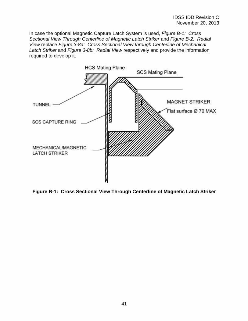
In case the optional Magnetic Capture Latch System is used, Figure B-1: Cross Sectional View Through Centerline of Magnetic Latch Striker and Figure B-2: Radial View replace Figure 3-8a: Cross Sectional View through Centerline of Mechanical Latch Striker and Figure 3-8b: Radial View respectively and provide the information required to develop it.
Figure B-1: Cross Sectional View Through Centerline of Magnetic Latch Striker
IDSS IDD Revision C November 20, 2013
42
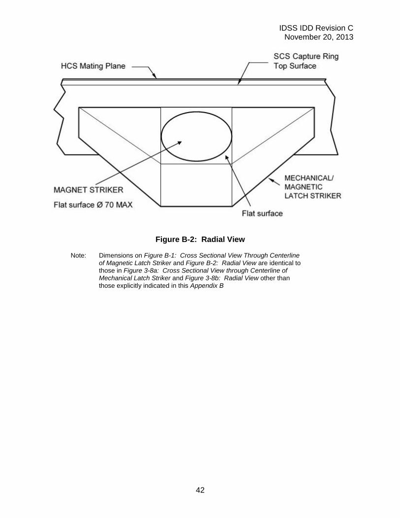
Figure B-2: Radial View
Note: Dimensions on Figure B-1: Cross Sectional View Through Centerline of Magnetic Latch Striker and Figure B-2: Radial View are identical to those in Figure 3-8a: Cross Sectional View through Centerline of Mechanical Latch Striker and Figure 3-8b: Radial View other than those explicitly indicated in this Appendix B
IDSS IDD Revision C November 20, 2013
43
APPENDIX C ACRONYMS AND ABBREVIATIONS
APAS Androgynous Peripheral Assembly System
C Celsius
CG Center of Gravity
CSA Canadian Space Agency
deg degree
ESA European Space Agency
F Fahrenheit
HCS Hard Capture System
hPa Hecto Pascal(s)
IDD Interface Definition Document
IDSS International Docking System Standard
ISS International Space Station
kg kilogram
kgf kilograms force
LEO Low Earth Orbit
m meters
MCB Multilateral Control Board
MEXT Ministry of Education, Culture, Sports, Science and Technology – Japan
MIN Minimum
mm Millimeters
MOI Moments of inertia
Minimum Material Condition
N Newton(s)
NASA National Aeronautics and Space Administration
NDS NASA Docking System
Nm Newton-Meter(s)
ODS Orbiter Docking System
ohm Ohms
Pa Pascal
POI Products of inertia
RF Radio Frequency
sec second
SCS Soft Capture System
SSRMS Space Station Remote Manipulator System
TBC To Be Confirmed
TBD To Be Determined
tonne metric ton = 1000 kilograms
M