Embed Size (px)
Citation preview
International Journal for Research in Engineering Application & Management (IJREAM)
ISSN : 2454-9150 Vol-03, Issue-12, Mar 2018
56 | IJREAMV03I123622 DOI : 10.18231/2454-9150.2018.0051 © 2018, IJREAM All Rights Reserved.
Design Analysis, Simulation and Fabrication of
Spur Gear Cutting Attachment for
Lathe Machine 1Gunturu Mohan,
2C. Vijayabhaskar Reddy
1UG Student,
2Professor, Sri Venkateswara College of Engineering Technology (Autonomous)
R V S Nagar, Chittoor, Andhra Pradesh, India.
Abstract—Lathe is a very important manufacturing subsystem in many sectors. Even though it is a versatile machine, it
has some limitations while performing certain operations like a spline, gear cutting. The use of milling machines in the
production of gear cutting is well recognized. This paper aims at the design and development of an attachment that can
help lathe operations to machine spur gear product effectively. Attachment is designed as able to cut spur gear
accurately and flexible to use. Milling machine cutting load and thrust loads is applied while doing the analysis. The
results are studied and analyzed whether the attachment is able to withstand the load with the help of ANSYS tool.
Finally, from the results obtained attachment is fabricated.
Keywords— Design, analysis, motion simulation, fabrication. Attachment assembly and machining.
I. INTRODUCTION
Job shops and small-scale industries are heavily constrained
to use general purpose machines due to financial limitations.
Machines such as Lathes and Milling machines are versatile
with these groups as they required minimum funding and are
easy to maintain. Researchers always attempt to help these
industries through innovative methods to enlarge the ambit
their production using these general purpose machines [1].
A variety of attachments are already in use by these
industries. As so far the literature reviews collected based on
some lathe machine attachments like the keyways, slotting,
internal keyway, and grinding wheel attachments for lathe
machine. These papers are helping lathe machine to obtain
maximum efficiency and utilization. literature collected on
gear cutting related journal explained about the parameters
to be considered while doing the design of an attachment
and required instructions to be considered while doing gear
cutting attachment for lathe machine.
J.C.Harbison (1994), [2] presented a milling attachment for
lathes. He modified the attachment that cutting tool fitted to
the arbor and that is supported by chuck and tailstock. He
modified direct indexing to compound indexing.
J.W.Bracus (1942), [3] presented a gear cutting attachment.
He was studied and modified smith’s attachment and he
tried to initiated indexing in the attachment.
T.E.Smith(1940), [4] presented a keyway and gear cutting
attachment for lathes. He is the initiator for this concept he
builds a gear and keyway cutting attachment for lathe by
adding another motor to the cutting tools and chuck
modified as holding and indexing device but this attachment
is heavy and complex.
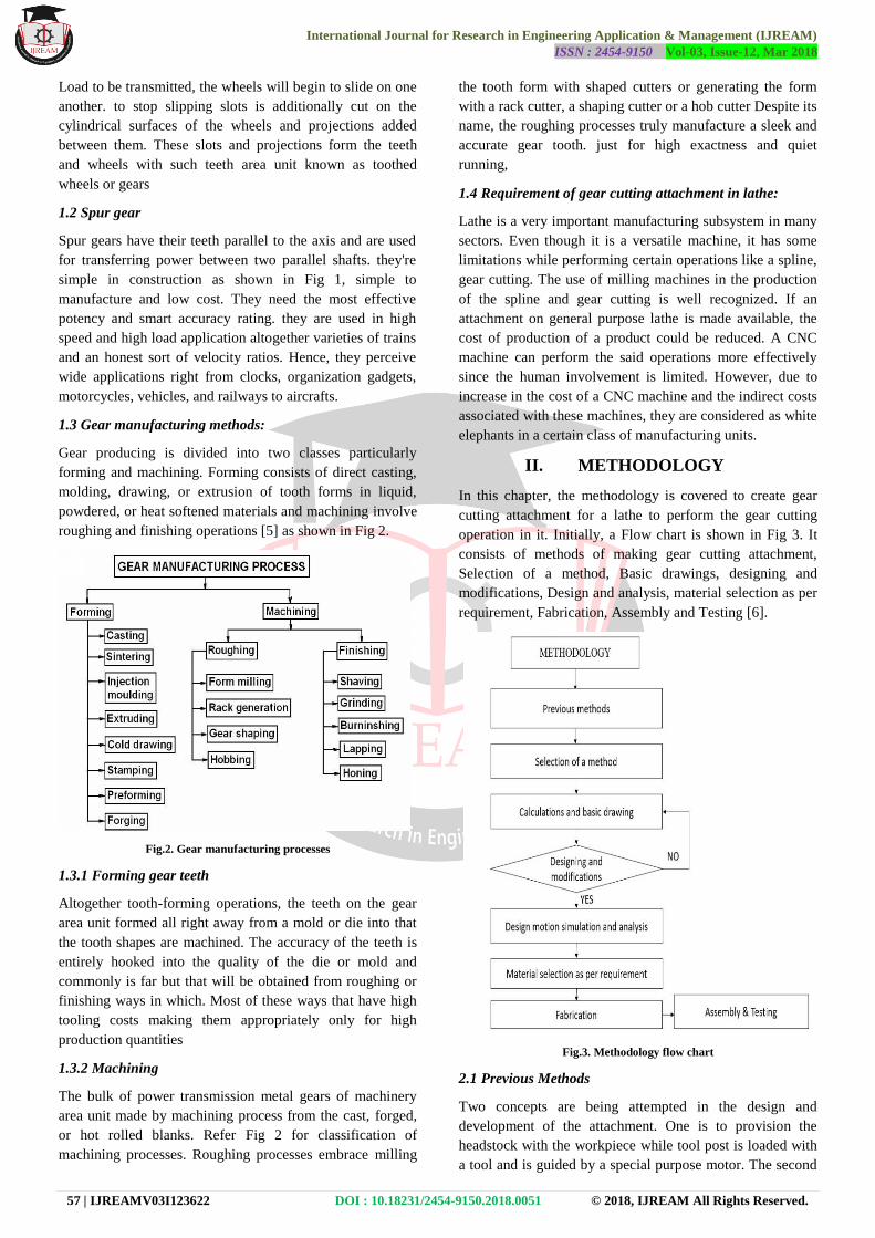
1.1 Gears
Assume that two plain wheels mounted bolt to two parallel
shafts and pressed tightly connected with one another. If one
wheel is rotated regarding its axis, the opposite wheel
conjointly can rotate due to the friction between them as
shown in Fig 1. The rotation is thus transmitted from one
shaft to another.
Fig.1. Gears
The surfaces of the two wheels will move at constant speed
if there is no slipping. it's obvious that with the increase in
International Journal for Research in Engineering Application & Management (IJREAM)
ISSN : 2454-9150 Vol-03, Issue-12, Mar 2018
57 | IJREAMV03I123622 DOI : 10.18231/2454-9150.2018.0051 © 2018, IJREAM All Rights Reserved.
Load to be transmitted, the wheels will begin to slide on one
another. to stop slipping slots is additionally cut on the
cylindrical surfaces of the wheels and projections added
between them. These slots and projections form the teeth
and wheels with such teeth area unit known as toothed
wheels or gears
1.2 Spur gear
Spur gears have their teeth parallel to the axis and are used
for transferring power between two parallel shafts. they're
simple in construction as shown in Fig 1, simple to
manufacture and low cost. They need the most effective
potency and smart accuracy rating. they are used in high
speed and high load application altogether varieties of trains
and an honest sort of velocity ratios. Hence, they perceive
wide applications right from clocks, organization gadgets,
motorcycles, vehicles, and railways to aircrafts.
1.3 Gear manufacturing methods:
Gear producing is divided into two classes particularly
forming and machining. Forming consists of direct casting,
molding, drawing, or extrusion of tooth forms in liquid,
powdered, or heat softened materials and machining involve
roughing and finishing operations [5] as shown in Fig 2.
Fig.2. Gear manufacturing processes
1.3.1 Forming gear teeth
Altogether tooth-forming operations, the teeth on the gear
area unit formed all right away from a mold or die into that
the tooth shapes are machined. The accuracy of the teeth is
entirely hooked into the quality of the die or mold and
commonly is far but that will be obtained from roughing or
finishing ways in which. Most of these ways that have high
tooling costs making them appropriately only for high
production quantities
1.3.2 Machining
The bulk of power transmission metal gears of machinery
area unit made by machining process from the cast, forged,
or hot rolled blanks. Refer Fig 2 for classification of
machining processes. Roughing processes embrace milling
the tooth form with shaped cutters or generating the form
with a rack cutter, a shaping cutter or a hob cutter Despite its
name, the roughing processes truly manufacture a sleek and
accurate gear tooth. just for high exactness and quiet
running,
1.4 Requirement of gear cutting attachment in lathe:
Lathe is a very important manufacturing subsystem in many
sectors. Even though it is a versatile machine, it has some
limitations while performing certain operations like a spline,
gear cutting. The use of milling machines in the production
of the spline and gear cutting is well recognized. If an
attachment on general purpose lathe is made available, the
cost of production of a product could be reduced. A CNC
machine can perform the said operations more effectively
since the human involvement is limited. However, due to
increase in the cost of a CNC machine and the indirect costs
associated with these machines, they are considered as white
elephants in a certain class of manufacturing units.
II. METHODOLOGY
In this chapter, the methodology is covered to create gear
cutting attachment for a lathe to perform the gear cutting
operation in it. Initially, a Flow chart is shown in Fig 3. It
consists of methods of making gear cutting attachment,
Selection of a method, Basic drawings, designing and
modifications, Design and analysis, material selection as per
requirement, Fabrication, Assembly and Testing [6].
Fig.3. Methodology flow chart
2.1 Previous Methods
Two concepts are being attempted in the design and
development of the attachment. One is to provision the
headstock with the workpiece while tool post is loaded with
a tool and is guided by a special purpose motor. The second

International Journal for Research in Engineering Application & Management (IJREAM)
ISSN : 2454-9150 Vol-03, Issue-12, Mar 2018
58 | IJREAMV03I123622 DOI : 10.18231/2454-9150.2018.0051 © 2018, IJREAM All Rights Reserved.
method is that the headstock containing the tool is going to
rotate at various speeds while the tool post or tailstock
contains workpiece for holding, cutting angle and changing
direction to perform gearing and slotting operations.
2.2 Selection of A Method
This project, therefore, aims at the design and development
of an attachment that can help lathe operations to produce
splines and gears of a product effectively and also realize
cost reduction. It is essential that the product quality should
be made comparable with that of milling operation or even
better. Ways and means will be found to incorporate features
both at design stage and production stage to achieve this
goal. Such an attachment will increase the flexibility of the
lathe.
After analyzing the methods, In the end, choose the method
based on some consideration like work piece holding
tendency external bodies to be attached in lathe machine
regarding complete setup it should be strong, safety,
flexible, low cost and also it should be easy to attach and
remove.
By considering all these things thefirst method was chosen.
2.3 Design of Indexing and Spur Gear
2.3.1 Indexing [8]
In general, direct indexing plate has 24 holes in a circle
The workpiece is divided by using the formula
Holes by which pin is to be moved = 24/n
n = no divisions in work piece
by this direct indexing plate, these many slots can be cut
2 divisions in work piece = 24/2 = 12 holes
3 divisions in work piece = 24/3 = 8 holes
4 divisions in work piece = 24/4 = 6 holes
6 divisions in work piece = 24/6 = 4 holes
8 divisions in work piece = 24/8 = 3 holes
12 divisions in work piece = 24/12 = 2 holes
24 divisions in work piece = 24/24 = 1holes
2, 3, 4, 6, 8, 12, 24.
To get other divisions I have taken 18 holes in the same
plate
2 divisions in work piece = 18/2 = 9 holes
3 divisions in work piece = 18/3 = 6 holes
6 divisions in work piece = 18/6 = 3 holes
9 divisions in work piece = 18/9 = 2 holes
18 divisions in work piece = 18/18 = 1 holes
2, 3, 6, 9, 18
2.3.2 Spur gear creation [7]
Whole Depth (W) = 2.157/P
Addendum (a) = 1/P
Tooth Radius (R) = ¾(CP)
Pitch Diameter (D1) = N/P
Circular Pitch (CP) = 3.1416/P
Diametral Pitch (P) = N/D1
Teeth number (N) = D1xD
Dedendum (d) = W-a
Outside Diameter (D) = (N+2)/P
Cordial Thickness (T) = D1sin(90/N)
Fig.4. Spur gear nomenclature
Work piece diameter 50 mm
For this work piece if the number of teeth 18 then the gear
parameters will be
1) Outside Diameter D = (N+2)/P
Outside Diameter = 50 mm
Teeth number = 18
50 = (18+2)/P
P = 20/50
= 0.4 mm
2) Pitch Diameter D1 = N/P
P = 0.4
D1 = 18/0.4
= 45 mm
3) Addendum a = 1/P
= 1/0.4
= 2.5 mm
4) Dedendumd = w-A
5) Whole Depth W = 2.157/P
= 2.157/0.4
= 5.3925
D = 5.3925 – 2.5
= 2.8925 mm
6) Circular Pitch CP = 3.1416/P
= 3.1416/0.4
= 7.854 mm
7) Tooth Radius R = ¾(CP)
= ¾ (7.854)
= 2.94 mm
8) Module m = D1/N
= 45/18
= 2.5
9) Chordal thickness T = D1 sin(90/N)
= 45 sin (90/18)
= 3.922 mm
Workpiece diameter 50 mm
For this workpiece, if the number of teeth 24 then the gear
parameters will be
1) Outside Diameter OD = (N+2)/P
Outside Diameter = 50 mm
Teeth number = 24
International Journal for Research in Engineering Application & Management (IJREAM)
ISSN : 2454-9150 Vol-03, Issue-12, Mar 2018
59 | IJREAMV03I123622 DOI : 10.18231/2454-9150.2018.0051 © 2018, IJREAM All Rights Reserved.
50 = (24+2)/P
P = 26/50
= 0.52 mm
2) Pitch Diameter D1 = N/DP
P = 0.52
D1 = 24/0.52
= 46.15 mm
3) Addendum a = 1/DP
= 1/0.52
= 1.92 mm
4) Dedendum d = w-A
5) Whole Depth W = 2.157/P
= 2.157/0.52
= 4.15 mm
d = 4.15 – 1.92
= 2.23 mm
6) Circular Pitch CP = 3.1416/P
= 3.1416/0.52
= 6.04 mm
7) Tooth Radius R = ¾(CP)
= ¾ (6.04)
= 4.53 mm
8) Module m = D1/N
= 46.15/24
= 1.922
9) Chordal thickness T = D1 sin(90/N)
= 46.15 sin (90/24)
= 26.38 mm
III. MODELLING
All CAD models are modeled with help of CATIA V5 tool.
Modeling of parts is divided into 5 steps
Basic lathe.
Attachment design.
Work holding design.
Tool holding design.
Assembly.
3.1 Basic lathe
Modeling basic lathe deals with basic lathe parts. These
parts specifications are taken from general purpose standard
lathe and few are assumed measurements. Modeled parts
names are given below.
Lathe bed
Headstock
Tailstock
Carriage
Chuck
Cross slide
Carriage wheel
Cross slide wheel
Power shaft
3.2 Attachment model
Attachment modeling deals with necessary parts required to
hold and guide the work piece to perform the operation.
Parts modeled for attachment is given below.
Main base with guides.
Supporting base with guides.
Cap.
Main guide center.
Supporting guide center
Shaft with thread.
3.3 Work holding design
Work holding modeling is nothing but modeling required
parts to hold the work piece between centers.
3.4 Tool holding design
To accomplish machining it is necessary to insert toll
between headstock and tailstock. Required models are made
to insert tool.
3.5 Assembly
Fig.5. Detail view
In assembly stage, Bottom to top approach was selected to
perform assembly in assembly workbench. Each part
dragged in to assembly workbench and accomplished
assembly. The detail view is shown in Fig 5 Initially,
themain base and supporting base with guides are fitted to
the cross slide with base nuts and bolts. Threaded shafts are
fitted to centers of main and support. This subassembly is
fitted to the main base and supporting bases. Now caps are
fitted to base and shaft with help of rows. As shown in Fig 6
This sub assembly is attached the cross slide. Now work
piece is aligned in between two bases with help of work
holding the device. pulleys aligned to the threaded shaft.
Belt arranged in-between two pulleys. Indexing plate
attached to work holder which is fitted to the center of the

International Journal for Research in Engineering Application & Management (IJREAM)
ISSN : 2454-9150 Vol-03, Issue-12, Mar 2018
60 | IJREAMV03I123622 DOI : 10.18231/2454-9150.2018.0051 © 2018, IJREAM All Rights Reserved.
main guide, both ends are tightened by hexagonal nuts as
shown in Fig 6.
Fig.6. Details of assembly
.5.1 Final assembly
Detailed view of final assembly is shown in Fig 7
Fig.7.Final modified assembly
3.5.2 Rendered image
Rendering is nothing but converting 2D or 3D models in to
realistic images. Rendered image of lathe machine with
attachment is shown in Fig 8
Fig.8. Rendered image
IV. MOTION SIMULATION AND
ANALYSIS
4.1 Motion simulation
To perform motion simulation we chosen solid works
motion simulator so all Catia v5 parts are converted from
‘.catpart and .catproduct’ in to ‘.igs’ format. All required
motions are applied to the assembly parts and the final
animated video was saved. Motions applied to the assembly
parts are illustrated in Table 1
S.NO
PARTS
X
linear
(mm)
X
rotation
(RPM)
Y
linear
(mm)
Y
rotation
(RPM)
Z
linear
(mm)
Z
rotation
(RPM)
1 Carriage -200 0 0 0 0 0
2 Centers 0 0 0 0 -100 0
3 Cross
slide
0 0 150 0 0 0
4 chuck 0 600 0 0 0 0
5 other 0 0 0 0 0 0
Table.1. Motion simulation details
Initially, motion applied to the carriage to position the work
with respect to cutting tool as carriage -200 mm linear
motion in x-direction after moving the carriage in x negative
direction check weather tool and work are properly arranged
or not if it is arranged then give linear motion to the shaft by
applying screw joint in between center and shaft. Center
linear motion in z negative direction i.e., -100 mm by this
motion depth of cut applied.
Next motion is given to the cross slide in y positive direction
150 mm this is like guiding workpiece towards cutting tool
for machining. Before doing all these things rotary motion
given to the cutting tool i.e., chuck 600 rpm. Now align the
timer in a sequence to perform motion simulation. Checked
all motions given to the parts and result video were saved.
Sample video frame was shown in Fig 9
Fig.9. Simulation frame image

International Journal for Research in Engineering Application & Management (IJREAM)
ISSN : 2454-9150 Vol-03, Issue-12, Mar 2018
61 | IJREAMV03I123622 DOI : 10.18231/2454-9150.2018.0051 © 2018, IJREAM All Rights Reserved.
4.2 Analysis
In analysis stage, we have considered two forces which exist
in milling machine operation
I. Cutting force
II. Thrust force
I. Cutting force
Power (P) = 1 kw
Cutter diameter(D) = 45 mm
Speed of chuck (N) = 600 rpm
Velocity (V) = πDN / 60
= (π*0.045*600)/60
V = 1.88 m/s
Power (P) = F. V
Cutting force (F) = P / V
= 1000/1.88
F1 =796 N
F2 =7960 N Taken for test attachment strength.
II. Thrust force
Cutter diameter (D) = 45 mm
Speed of chuck (N) = 600 rpm
Thrust force constant (K) = 42.35
Feed rate (f) = 1.5 mm/min
Thrust force (th) = K*N*D*f^0.7
=
42.35*600*0.045*1.5^0.7
= 1200 N
All parameters are taken from general purpose lathe and
milling machine Now these values will be applying on the
modeled assembly structure and analyzed by using ansys
software ‘static structural analysis’
Terms are going to find with this analysis:
Equivalent elastic stress (von- mises)
Equivalent stress (von- mises)
Max shear stress
Maximum principal elastic strain
Units:
Units considered while doing analysis stage are shown in
Table 5.2
Unit system Metric (mm, kg, mv) Degree
red/s
Angle Degree
Rotational velocity red/s
Table.2. Units
Meshing:
Meshing details are given in Table 3
Object Name Mesh
State Solved
Display
Display Style Body Color
Defaults
Physics Preference Mechanical
Relevance 0
Element Order Program
Controlled
Sizing
Size Function Adaptive
Relevance Center Fine
Element Size 5.0 mm
Initial Size Seed Assembly
Transition Fast
Span Angle Center Coarse
Automatic Mesh Based Defeaturing On
Defeature Size Default
Minimum Edge Length 2.50 mm
Table.3. Meshing
Equivalent elastic stress (von- mises):
Equivalent elastic stress i.e., von- mises stresses is show
in Fig 10
Fig.10. Equivalent elastic stress in MPa
Equivalent stress (von- mises)
Equivalent stress is shown in Fig 11
Fig.11. Equivalent stress
Max shear stress:
Max shear stress is shown in Fig 12
Fig.12. Max shear stress in MPa

International Journal for Research in Engineering Application & Management (IJREAM)
ISSN : 2454-9150 Vol-03, Issue-12, Mar 2018
62 | IJREAMV03I123622 DOI : 10.18231/2454-9150.2018.0051 © 2018, IJREAM All Rights Reserved.
Maximum principal elastic strain
The maximum principal elastic strain is shown in Fig
13
Fig.13.Maximum principal elastic strain
Simulation calculations:
Hence stress concentration factor F1 (α˳) =
=31.8
Hence stress concentration factor F2 (α˳) =
=
=3.17
Hence stress concentration factor for F1 and F2 are in save
zone. The maximum load can apply on the attachment is
7960 N and the load which we have collected from the
milling machine is 796 N stress concentration factor is far
most saver side so that we can consider the attachment can
accept the load analysis stage successfully completed. All
results are verified and the modeled assembly design is in
safe condition now moving into next step i.e., material
selection and fabrication.
V. MATERIAL SELECTION &
FABRICARION
5.1 Material Selection
The material what we have to select that should be less
costly and available every ware So that all job shops can use
this attachment easily. That is why we have chosen stainless
steel as the standard for the structure. For few parts like
threaded shaft and center, we have taken another grade of
stainless steel which consists more hardness than existing
one.
5.2 Fabrication Work
In fabrication stage production drawings are produced for
main and supporting bases with supports, a center for the
main base and supporting bases, caps, work holding and tool
holding shafts, andthreaded shafts. These are fabricated one
by one. In the end, all parts are assembled and attached to
the lathe. One of its Subassembly is shown in Fig 14. It is
main base sub assembly combines with the main base with
guides, cap, threaded shaft, center part, few screws, and
bolts.
Fig.14. main base assembly
5.3 Attaching the attachment to the lathe:
In general, lathe consists of tool post mounts on the cross
slide but to attach this attachment to the lathe tool post is
removed as shown in Fig 15
Fig.15. Carriage
After fitting main and supporting bases to the carriage,
Pulleys and belt are fitted to threaded shafts to transfer
rotary motion from main base shaft to supporting base shaft.
This will help centers to maintain equal vertical motions
shown in Fig 16
Fig.16. Final assembly
VI. FEATURES, RESULTS, AND
CONCLUSION
6.1 Advantages
Initial cost will be reduced.
Flexible in operation.
Simple in operation and no need for a skilled
operator.
Good accuracy can be achieved.

International Journal for Research in Engineering Application & Management (IJREAM)
ISSN : 2454-9150 Vol-03, Issue-12, Mar 2018
63 | IJREAMV03I123622 DOI : 10.18231/2454-9150.2018.0051 © 2018, IJREAM All Rights Reserved.
Simple construction.
Easy to install.
Work piece diameter can be extended up to
200mm
6.2 Disadvantages
Spline gear cutting work piece thickness should
not exceed 150 mm.
There is a chance to get vibration during
operation.
Hard material like high carbon steel cannot be cut
(unless until structure should make up of strong
metal like cast iron etc.).
6.3 Area of Application
Production of the spur gear, spline shaft, grooves
etc.
In small workshop where milling machine is not
affordable.
VII. RESULTS AND CONCLUSION
The attachment is made to cut spur gear which is done by
Modeling and assembly of CAD parts are accomplished by
CATIA V5 software. Motion simulation was done by
SolidWorks motion simulator software and the video was
recorded. The static structural analysis was done by ANSYS
software and results are examined. Fabrication of the
attachment is completed by using raw material as stainless
steel. Final fabricated model is fitted to the lathe machine
and sample gear is produced. Produced samples might
competitive with milling accuracy. A lot of investment is
saved instead of buying a gear cutting machine. Also by
using this attachment production cost of making gear also
reduced.
VIII. FUTURE SCOPE
In this attachment direct indexing chosen as dividing head.
This has particular limitation it is only a few no of divisions
can make by using this attachment. This limitation can
overcome by using compound indexing. If the centeris
combined with bushes, then the shaft wear and tear will be
reduced material like cast iron and stainless steel will be
improving the strength of the attachment and that will allow
us to perform almost all horizontal milling operations
REFERENCES
[1] JahnaviMadireddy“Importance of Lathe Machine in
Engineering Field and Its Usage”ISSN: 2249-4596.,
2014
[2] J.C.Harbison“Milling Attachment for Lathes”
No: 2453315., Nov. 9, 1948
[3] J.W.Bracus“Gear Cutting Attachment”No:2286709.,
June 16, 1942
[4] T.E.Smith“Keyway and Gear Cutting Attachment
for Lathes”
US; No: 2188447., Jan 30, 1940
[5] GadakhRamesh S, Londhepradip G, Shaikh Bilal A And
Shaikhfiroj S “Gear Manufacturing By Using
Conventional Lathe Machine”
eissn: 2319-1163 | pissn: 2321-7308
[6] Sagar, Mr. Neeraj Kumar and Mr. Jagbir Sharma
“Analysis of Spur Gear Cutting Using Milling
Machine”
issn: 2347 – 4718., february-2016, issn: 2320-2092.,
aug.-2016
[7] Dr. Ramachandra C G, Shashank S, Raghavendra M J
and Kaushikranganath T “Design and Fabrication of
Gear Cutting Attachment for Lathe” e-issn: 2454-
6135., oct -2017
[8] R. K. Jain “Production Technology” Page no: 891 to
894


![[1] involuteΣiii(spur and helical gear design system)Spur...1 [1] involuteΣiii(spur and helical gear design system) 図1.1 involuteΣiii(spur and helical) 1.1 概要 involuteΣⅲ(spur](https://img.pdfslide.net/doc/110x75/5ae0683d7f8b9a97518d2bd7/1-involuteiiispur-and-helical-gear-design-system-spur1-1-involuteiiispur.jpg)