Embed Size (px)
Citation preview

Babita Yet al / Int. J. of Allied Med. Sci. and Clin. Research Vol-5(4) 2017 [839-861]
839
IJAMSCR |Volume 5 | Issue 4 | Oct-Dec - 2017 www.ijamscr.com
Research article Medical research
A comparative radiographic evaluation of condylar position in wax check
bite record; gothic arch tracing and post insertion of complete denture
Dr.Babita Yeshwante1, Dr.R.D.Parkhedkar
CSMSS Dental College and Hospital, Kanchanwadi, Aurangabad-431002. *Corresponding Author: Dr. BabitaYeshwante
ABSTRACT
Aim
To determine the position of condyle radiographically in the wax check bite stage, the Gothic arch tracing and post
insertion of denture to decide the clinically comfortable position of condyle at the dentulous and edentulous state can
be determined by radiographic means.
Method
10 male patients from age group 45 to 65 years were selected. In order to standardize the intracranial radiograph of
either side a modified radiographic head positioner was fabricated. For infracranial radiography, the patient was
seated in the chair in the same position as that when the jaw relation was recorded. the relative position of condyle by
radiographic means in different clinical stages i.e. in wax check bite record, Gothic arch tracing and post insertion of
complete denture was recorded. Tracing of radiograph were obtained. And based on it study was concluded.
Result
It showed that the position of condyles is posterior most in gothic arch tracing, anterior most in the wax check bite
record the position of condyle was anterior to gothic arch tracing and posterior to tentative jaw relation after denture
insertion.
Conclusion
Findings showed that there existed unequal joint space between the head of condyle and the glenoid fossa at various
stages of denture.
INTRODUCTION
Among the many concepts in denture
construction which have been accepted by many
professionals, the concept of the "Centric position"
stands out as the vaguest and most ambiguous,
Although certainly one of the most important.
Recent research into Temporomandibular joint
function suggest that a Re-evaluation of basic
hypotheses indicated. Commonly accepted
premises are taken and scientific facts because they
are familiar and they produce empirically
acceptable results. The position of the mandibular
condyles in the glenoid fossae is an important
factor for the success of prosthodontics treatment
which may otherwise lead to temporomandibular
joint disorders, myofascial pain dysfunction
syndrome. while treating a complete edentulous
patient we are supposed to establish the centric
occlusion at the recorded centric relation. After
recording the centric relation in wax check bite
ISSN:2347-6567
International Journal of Allied Medical Sciences
and Clinical Research (IJAMSCR)

Babita Yet al / Int. J. of Allied Med. Sci. and Clin. Research Vol-5(4) 2017 [839-861]
840
record or in Gothic arch tracing method,
Comparatively the position of the condyle should
be same.
According to kingery's [28] controversy, it was
thought that it is worthwhile to study if there is any
change in the position of condyle at various clinical
methods of recording jaw relation and post
insertion of complete denture and during various
steps in complete denture fabrication. The study
was planned to determine the position of condyle
radiographically in the wax check bite stage, the
Gothic arch tracing and post insertion of denture to
decide the clinically comfortable position of
condyle at the dentulous and edentulous state can
be determined by radiographic means.
AIMS AND OBJECTIVES
1. To find out the relative position of condyle by
radiographic means in different clinical stages
i.e. in wax check bite record, Gothic arch tracing
and post insertion of complete denture.
2. Recording of clinical centric in wax check bite
and its position of condyle.
3. Recording of clinical centric in Gothic arch
tracing state and its position of condyle.
4. Recording of clinical centric after denture
insertion and its position of condyle.
5. To check relative position of condyle at right
and left side and its variation in wax check bite
record, Gothic arch tracing and post denture
insertion.
6. To standardize the accurate head position of
patient and its relation to the X-ray machine by
modified head positioner.
7. To evaluate the success rate at different Stages
of denture preparation and after delivering the
prosthesis after 7days of follow-up was
determined.
MATERIALS AND METHODS
The following study was carried out in
Government Dental College and Hospital, Nagpur,
in the department of prosthetic dentistry. The study
was undertaken to determine the position of
condyle at various methods of recording centric
relation in wax check bite record and the Gothic
arch tracing and its effects in complete denture
fabrication by radiographic examination.
Criteria for selection of patients
10 male patients from age group 45 to 65 years
were selected amongst those visiting the
department of prosthetic dentistry. Such completely
edentulous patients were examined thoroughly.
Priority to the healthy oral conditions were given.
Conditions such as healthy alveolar ridges, non-
flabby tissues, normal TMJ movements, normal
ridge relationship, patient’s economic status,
General Health were taken into consideration.
Clinical examination and consent
A thorough clinical examination of the oral cavity and
extra oral structures was carried out. A detailed
history was obtained by direct questioning and
patients consent was taken.
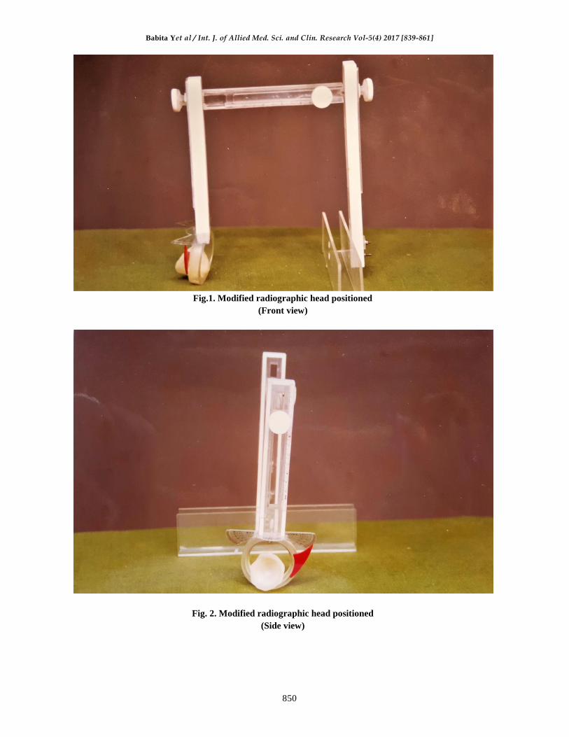
Radiographic head positioner
In order to standardize the infracranial radiograph of
either side a modified radiographic head positioner
was fabricated. It was similar to that of Arthur H.
Wuhermann's [1] metallic collimator holding
device. The localizer collimator is not available,
commercially but it can be custom made. The
localizer so constructed that the space between the
collimator and localizing nuts can be changed. The
relationship between the parts remain constant except
for the change in distance; opening or closing of
appliance must not change the level of the nut in their
relationship to the central Ray. Prior to initial use of
the localizer, the nuts must be adjusted and locked, so
that they are in exact centre of the radiation. The
present modified head positioner can be divided into
three parts:-
1. The horizontal bar to adjust the distance of cone
and film.
2. The vertical arm for holding the X-ray cone.
3. The vertical arm for holding the cassette of
radiographic film.
The horizontal bar
It consists of two rods; one embedded into
another which has a sliding mechanism. Also it
consists of a measuring scale and a thumb screw to
tighten the sliding rod. Measuring scale is so fixed
that the zero coincides with one end of the sliding
bar.
Babita Yet al / Int. J. of Allied Med. Sci. and Clin. Research Vol-5(4) 2017 [839-861]
841
Vertical arm for holding the X-ray cone
The cone is fabricated in clear methyl
methacrylate resin in which the X-ray cone fits. It
is mounted on an acrylic ring that has a taper and
rotates around an axis to adjust the horizontal
angulation with the help of screw.
The whole assembly can slide vertically
downwards and upwards with the help of the thumb
screw to which again a pointer is attached for
recording the readings. To measure the horizontal
angulation a protractor is fixed with a pointer
attached to the ring.
The vertical arm for holding the Cassette of
radiographic film
It consists of a "U" shaped cassette holding
device made up of clear acrylic resin at the lower
end. The whole cassette holding device can slide
with the help of thumb screw to which again a
pointer is attached to mark the readings.
Technique of infracranial radiograph
For the Infracranial projection, an X-ray film
cassette is positioned against the side of the
patients Head, parallel to the sagittal plane, next to
the TMJ of interest. The X-ray tube head is placed
on the side of the skull opposite the TMJ to be
imaged. It is angulated so that the control beam is
directed cranially 5 to 10 degrees and
approximately 10 degrees posteriorly. This position
ideally directs the central x-ray beam through the
tube side mandibular sigmoid notch, below the base
of the skull, through the oropharynx and finally
through the film.
Position of the patient and radiographic
headpositioner
For infracranial radiography, the patient was
seated in the chair in the same position as that
when the jaw relation was recorded. The
radiographic head positioner was positioned in such
way that the horizontal bar was touching the
patient's head. The cassette for radiographic size of
6"× 8" was placed in the "U" shape cassette holding
device and x-ray cone was placed in such a way
that it fixed snugly in the cone of same size and
shape of the radiographic head positioner.
Fabrication of complete dentures in balanced
occlusion
After thorough clinical evaluation and detailed
case history, complete denture for each patient was
fabricated in balanced occlusion following each
step meticulously. Initially the primary impression
in compound (Y-dents) was made. Primary Casts
were obtained in plaster of Paris and special trays
in tray material were made. Final impression was
recorded by establishing the peripheral seal in low
fusing compound (Aslate) and wash impression in
zinc oxide eugenol paste for (polynol). After
preparation of the final cast, permanent record
bases of heat curing polymethylmethacrylate resin
(stellon) were made by slow curing cycle. Jaw
relation was recorded by the wax check bite record.
After this the infracranial radiograph of either side
of TMJ as described in the technique was taken in
the department of oral diagnosis, medicine and
radiology of government Dental College and
Hospital, Nagpur. After the radiograph, face bow
record and transfer was done and extraoral Gothic
arch tracing were made. Intraoral plaster records
were made in centric relation and protrusive
position after which again radiographs of either
side were taken. Patients dentures were selected
and arranged in balanced occlusion after try-in, the
dentures were fabricated and delivered. patients
were asked to take care regarding the oral hygiene
and cleanliness of dentures. After 7 days when
patient was adapted to dentures, again radiographs
of either side were Taken with the same readings
on scale with dentures in centric occlusion in
patient's oral cavity.
Tracing of radiographs
The radiograph was checked for the quality and
clearance. The external auditory meatus, the
glenoid fossa and the head of the condyle was
traced with a microtip pen of black colour directly
on the X-ray by keeping it on the X-ray viewer. All
the tracings were then transferred on the graph
papers with the help of carbon paper.
Method of measurement
As described by Ismail and rokani in 198022
the method consists of considering the point M- the
center of external auditory meatus. From point M,
13 mm to the glenoid fossa, a point S its fixed,
which was taken to be the superior point of

Babita Yet al / Int. J. of Allied Med. Sci. and Clin. Research Vol-5(4) 2017 [839-861]
842
glenoidfossa and as another reference point. From
point S, 1cm posteriorly on the glenoidfossa, a point
P was fixed and was considered as the posterior
reference point. From point S anteriorly again 1cm
point A was fixed and was considered as the anterior
reference point. After fixing up the points, the
perpendicular lines from point S, P and A were drawn
on the head of condyle. The point thus obtained were
a S1, P1 and A 1 respectively. The tangents to
condylar surface through S1, P1 and A1 and parallel
lines passing through S, P and A, were drawn.The
distance between S and S1 was taken the superior
space between the Condyle and glenoid fossa; from P
to P1 the posterior space and A to A1 the anterior
space between condyle and glenoid fossa. The
readings were measured on the graph paper. The
reading were Taken of 6 radiographs of each patients;
two each shooted after wax check bite records, Gothic
arch tracing and 7 days of recall of the denture
insertion stage and thus the relative position of
condyle was observed.
DISCUSSION
Centric relation is a classical reference and
treatment position in complete denture Prosthesis.
It has been defined in so many different ways that
its creditability for the clinician is questionable.
According to glossary of prosthodontics term,
"centric relation is defined as the
maxillomandibular relationship in which the
condyles articulate with the thinnest avascular
portion of their respective disks with the complex
in the anterosuperior position against the slopes of
the articular eminences. This position is
independent of tooth contact. This position is
clinically discernible when the mandible is added
directed superiorly and anteriorly. It is restricted to
a purely rotary movement about the transverse
horizontal axis". The present study had tried to find
out the amount of displacement in condylar
position in relation to various methods of Jaw
relation record by TMJ radiographs. Radiographs
of either side of TMJ were made to check for the
position of condyle at three different stages.
1. Wax check bite record.
2. Gothic arch tracing and
3. Post denture insertion
The relative position of condyle was assessed
by measuring the spatial difference between the
glenoid fossa and the head of the condyle. The
present study has shown no significant difference
in the supero inferior position of condyle. The
second point is that the circumcondylar joint spaces
do not appear to have been of equal in size
radiographically. This finding was in agreement
with the finding of Lawrence A Weinberg[35].The
study also reveals that there is a significant change
in position of condyle in various methods of
recording centric relation.
In the present study, a significant change in the
position of condyle was found in different methods
of recording centric relation. The position of
condyle in wax check bite record was found to be
anterior than the position of condyle in Gothic arch
tracing method, also there was a significant change
in the position of condyle after the denture
insertion. The position of condyle after 7 days of
recall after denture delivery was found to be
anterior to the position of condyle in Gothic arch
tracing but the position was not as anterior as the
position in the wax check bite record.
Although the literature Bounds with many
studies done on the temporomandibular joint and
related structures, no attempts have been made to
study the position of condyle at various stages of
denture fabrication and to find the change in
relative position of condyles radiographically.
From the present study, we can state that the Gothic
arch tracing method is superior over the wax check
bite record method as the position of condyle lies
nearer to the Gothic arch tracing method after
denture insertion.
Since the TMJ radiographs serve as an
important aid in diagnosis and treatment planning,
in prosthodontics, in the planning of complete
denture treatment, it is essential to determine the
position of condyle after recording the centric
relation. This can be considered for the future
reference while treating the patient by new centric
relation. Hence the TMJ radiographs aid us to
determine the position of condyle in the centre
relation. It is to be noted that there were few
limitations in the study. Since the position of
condyle is an area, a three dimensional view is a
necessary to assess its position.

Babita Yet al / Int. J. of Allied Med. Sci. and Clin. Research Vol-5(4) 2017 [839-861]
843
RESULT
Table No 1. Showing values of measurement of distance Between S-S1, P-P1, A-A1 of right and left sides (in
mm)
S.NO. POINT TJR GAT DO
RIGHT LEFT RIGHT LEFT RIGHT LEFT
1. S-S1 2 1.5 1.5 1 3 2
P-P1 1 1 0.5 1.5 2 2.5
A-A1 2.5 1.5 2 2 1 0.5
2. S-S1 3 4 2.5 3 3 3
P-P1 2.5 2 2 1.5 2 3
A-A1 1.5 1 2.5 2 2.5 0.5
3. S-S1 2 1.5 1 2 2 1.5
P-P1 1.5 1 1 1 1.5 1
A-A1 0.5 0.5 2 2 1 2
4. S-S1 1.5 3 1 3 3 3
P-P1 2 1.5 1 1 1 1
A-A1 4 4 3 3 3 4
5. S-S1 4 4 2 3 3 3
P-P1 5 3 1 1.5 3 1.5
A-A1 2 1.5 0.5 2 1 1
6. S-S1 1.5 4 3 2 3 2
P-P1 1 2 1 1.5 1 2
A-A1 1 0.5 1 1.5 2 2
7.
S-S1 4 2 2 3 3 3
P-P1 4 2 1 2 2 2
A-A1 2 2 3 1 1 1
8. S-S1 4 2 2 2 1 2
P-P1 6 1 1 1 1 1
A-A1 1 2 2 2 1 1
9. S-S1 4 5 2 4 1 5
P-P1 3 2 2 1.5 1 1
A-A1 2 1 1 1 1 1
10. S-S1 1 1.5 2 1 1 1
P-P1 2 1.5 1.5 1 2 1.5
A-A1 4 5 2 4 4 2.5
Table no. 2 Showing the difference between TJR, GAT and DD of the right and left side
In mm
Pts No. POINTS From TJR to GAT From GAT to DD From TJR to DD
RIGHT LEFT RIGHT LEFT RIGHT LEFT
1 S-S1 0.5 0.5 1.5 1 1 0.5
P-P1 0.5 0.5 0.5 1 1 1.5
A-A1 0.5 0.5 1 1.5 1.5 1
2 S-S1 0.5 1 0.5 0 0 1
P-P1 0.5 0.5 0 1.5 0.5 1
A-A1 1 1 0 1.5 1 0.5
3 S-S1 1 0.5 1 0.5 0 0
P-P1 0.5 0 0.5 0 0 0
A-A1 1.5 1.5 1 0 0.5 1.5
4 S-S1 0.5 0 2 0 1.5 0
Babita Yet al / Int. J. of Allied Med. Sci. and Clin. Research Vol-5(4) 2017 [839-861]
844
P-P1 1 0.5 0 0 1 0.5
A-A1 1 1 0 1 1 0
5 S-S1 2 1 1 0 1 1
P-P1 4 1.5 2 0 2 1.5
A-A1 1.5 0.5 0.5 1 1 0.5
6 S-S1 1.5 2 0 0 1.5 2
P-P1 0 0.5 0 0.5 0 0
A-A1 0 1 1 0.5 1 1.5
7 S-S1 2 1 1 0 1 1
P-P1 3 0 1 0 2 0
A-A1 1 1 1 2 1 1
8 S-S1 2 0 1 0 3 0
P-P1 5 0 0 0 5 0
A-A1 1 0 1 1 0 1
9 S-S1 2 1 1 1 3 0
P-P1 1 0.5 1 0.5 2 1
A-A1 1 0 1 0 1 0
10 S-S1 1 0.5 1 0 0 0.5
P-P1 0.5 0.5 0.5 0.5 0 0
A-A1 2 1 2 1.5 0 2.5
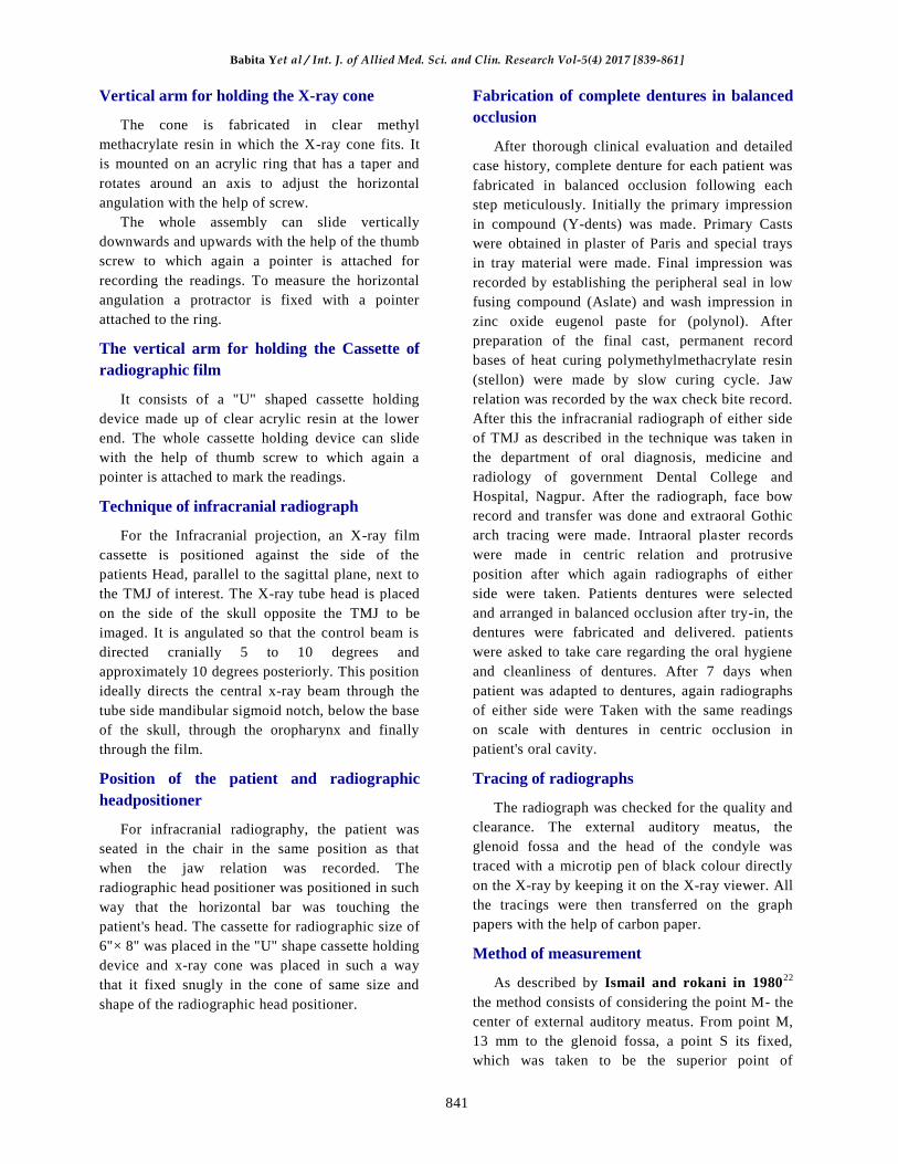
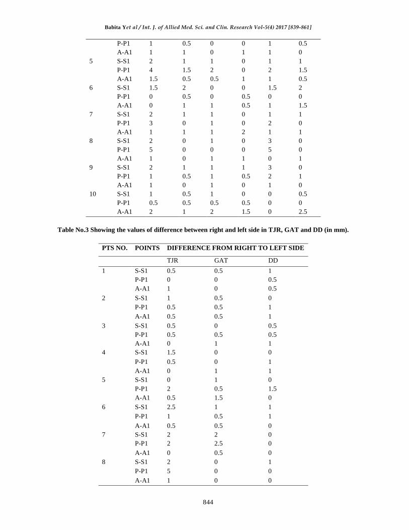
Table No.3 Showing the values of difference between right and left side in TJR, GAT and DD (in mm).
PTS NO. POINTS DIFFERENCE FROM RIGHT TO LEFT SIDE
TJR GAT DD
1 S-S1 0.5 0.5 1
P-P1 0 0 0.5
A-A1 1 0 0.5
2 S-S1 1 0.5 0
P-P1 0.5 0.5 1
A-A1 0.5 0.5 1
3 S-S1 0.5 0 0.5
P-P1 0.5 0.5 0.5
A-A1 0 1 1
4 S-S1 1.5 0 0
P-P1 0.5 0 1
A-A1 0 1 1
5 S-S1 0 1 0
P-P1 2 0.5 1.5
A-A1 0.5 1.5 0
6 S-S1 2.5 1 1
P-P1 1 0.5 1
A-A1 0.5 0.5 0
7 S-S1 2 2 0
P-P1 2 2.5 0
A-A1 0 0.5 0
8 S-S1 2 0 1
P-P1 5 0 0
A-A1 1 0 0

Babita Yet al / Int. J. of Allied Med. Sci. and Clin. Research Vol-5(4) 2017 [839-861]
845
9 S-S1 1 2 4
P-P1 1 0.5 0
A-A1 1 0 0
10 S-S1 0.5 1 0
P-P1 0.5 0.5 0.5
A-A1 1 2 1.5
Table no. 4. Showing the mean value of the right and left sides
POINT TJR GAT DD
RIGHT LEFT RIGHT LEFT RIGHT LEFT
S-S1 2.70 2.85 1.90 2.40 2.30 2.55
P-P1 2.80 1.70 1.20 1.35 1.65 1.65
A-A1 2.05 1.90 1.90 2.05 1.70 1.55
Table no. 5 showing the standard deviation value of the right and left sides
POINT TJR GAT DD
RIGHT LEFT RIGHT LEFT RIGHT LEFT
S-S1 1.22 1.31 0.61 0.96 0.94 1.11
P-P1 1.70 0.63 0.48 0.33 0.66 0.70
A-A1 1.18 1.48 0.84 0.89 1.07 1.09
Table no. 6 showing the difference between the mean value of TJR, gat and DD of the right and left side (in
mm)
POINTS FROM TJR TO GAT FROM GAT TO DD FROM TJR TO DD
RIGHT LEFT RIGHT LEFT RIGHT LEFT
S-S1 0.80 0.45 0.40 0.15 0.40 0.30
P-P1 1.60 0.35 0.45 0.30 1.15 0.05
A-A1 0.15 0.20 1.20 0.50 0.35 0.35
Table No. 7.Showing the‘t’ value of TJR,GATand DD of the right and let side
POINTS FROM TJR TO GAT FROM GAT TO DD FROM TJR TO DD
RIGHT LEFT RIGHT LEFT RIGHT LEFT
S-S1 0.90 0.90 1.20 0.33 0.85 0.56
P-P1 2.11 2.40 2.30 2.74 1.90 2.42
A-A1 2.42 2.68 2.32 2.80 2.10 2.32
Table No.8.Showing the significance in percentage values of the TJR,GAT and DD of right and left side.
POINTS FROM TJR TO GAT FROM GAT TO DD FROM TJR TO DD
RIGHT LEFT RIGHT LEFT RIGHT LEFT
S-S1 NS NS NS NS NS NS
P-P1 0.05% 0.03% 0.02% 0.01% 0.07% 0.05%
A-A1 0.03% 0.02% 0.02% 0.02% 0.05% 0.05%
Babita Yet al / Int. J. of Allied Med. Sci. and Clin. Research Vol-5(4) 2017 [839-861]
846
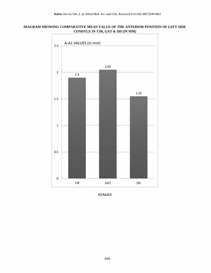
DIAGRAM SHOWING COMPARATIVE MEAN VALUE OF THE ANTERIOR POSITION OF LEFT SIDE
CONDYLE IN TJR, GAT & DD (IN MM)
STAGES
1.9
2.05
1.55
0
0.5
1
1.5
2
2.5
TJR GAT DD
A-A1 VALUES (in mm)

Babita Yet al / Int. J. of Allied Med. Sci. and Clin. Research Vol-5(4) 2017 [839-861]
847
DIAGRAM SHOWING COMPARATIVE MEAN VALUE OF THE ANTERIOR POSITION OF RIGHT
SIDE CONDYLE IN TJR, GAT & DD (in mm)
STAGES
2.05
1.9
1.7
0
0.5
1
1.5
2
2.5
TJR GAT DD
A-A1 VALUES (in mm)

Babita Yet al / Int. J. of Allied Med. Sci. and Clin. Research Vol-5(4) 2017 [839-861]
848
DIAGRAM SHOWING COMPARATIVE MEAN VALUE OF THE POSTERIOR POSITION OF LEFT
SIDE CONDYLE IN TJR, GAT & DD (in mm)
STAGES
1.7
1.35
1.65
0
0.5
1
1.5
2
TJR GAT DD
P-P1 VALUES (in mm)

Babita Yet al / Int. J. of Allied Med. Sci. and Clin. Research Vol-5(4) 2017 [839-861]
849
DIAGRAM SHOWING COMPARATIVE MEAN VALUE OF THE POSTERIOR POSITION OF RIGHT
SIDE CONDYLE IN TJR, GAT & DD (in mm)
STAGES
2.8
1.2
1.65
0
0.5
1
1.5
2
2.5
3
3.5
TJR GAT DD
P-P1 VALUES (in mm)
Babita Yet al / Int. J. of Allied Med. Sci. and Clin. Research Vol-5(4) 2017 [839-861]
850
Fig.1. Modified radiographic head positioned
(Front view)
Fig. 2. Modified radiographic head positioned
(Side view)

Babita Yet al / Int. J. of Allied Med. Sci. and Clin. Research Vol-5(4) 2017 [839-861]
851
Fig. 3. Armamentarium
Fig. 4. Patient Selection
Babita Yet al / Int. J. of Allied Med. Sci. and Clin. Research Vol-5(4) 2017 [839-861]
852
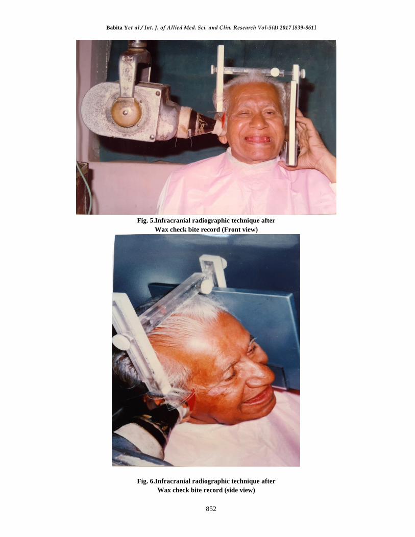
Fig. 5.Infracranial radiographic technique after
Wax check bite record (Front view)
Fig. 6.Infracranial radiographic technique after
Wax check bite record (side view)

Babita Yet al / Int. J. of Allied Med. Sci. and Clin. Research Vol-5(4) 2017 [839-861]
853
Fig .7.infracranial radiographic technique after gothic arch tracing
(Front view)
Fig.8.Infracranial radiographic technique aftergothic arch tracing
(side view)

Babita Yet al / Int. J. of Allied Med. Sci. and Clin. Research Vol-5(4) 2017 [839-861]
854
Fig .9. Transfer of jaw relation on the Hanau (H2 series non arcon) articulator
Fig .10.Trial denture on the articulator

Babita Yet al / Int. J. of Allied Med. Sci. and Clin. Research Vol-5(4) 2017 [839-861]
855
Fig .11.Infracranial radiographic technique after denture insertion (front view)
Fig .12.infracranial radiographic technique after denture insertion (Side view)
Babita Yet al / Int. J. of Allied Med. Sci. and Clin. Research Vol-5(4) 2017 [839-861]
856
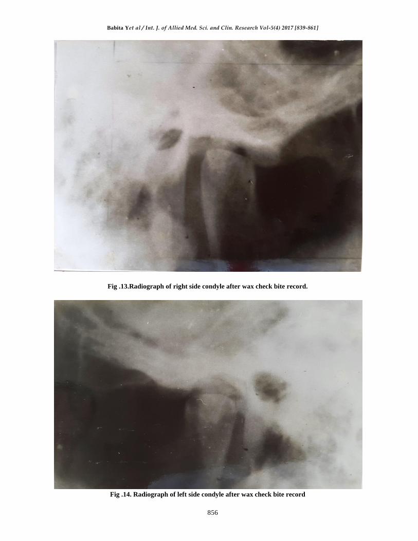
Fig .13.Radiograph of right side condyle after wax check bite record.
Fig .14. Radiograph of left side condyle after wax check bite record
Babita Yet al / Int. J. of Allied Med. Sci. and Clin. Research Vol-5(4) 2017 [839-861]
857
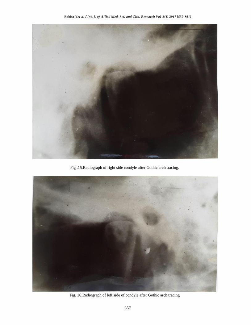
Fig .15.Radiograph of right side condyle after Gothic arch tracing.
Fig. 16.Radiograph of left side of condyle after Gothic arch tracing

Babita Yet al / Int. J. of Allied Med. Sci. and Clin. Research Vol-5(4) 2017 [839-861]
858
Fig .17. Radiograph of right side condyle after denture insertion
Fig .18. Radiograph of left side condyle after denture insertion

Babita Yet al / Int. J. of Allied Med. Sci. and Clin. Research Vol-5(4) 2017 [839-861]
859
In the present study, the position of condyle was
determined in wax check bite record, Gothic arch
tracing and post insertion of denture by
radiographic means. Ten edentulous male patients
were selected for the purpose of study.
To find the significance between change in
position of condyles, distance between points S-SI,
P-PI and A-AI in wax check bite records, Gothic
arch tracking and after denture insertion was
subjected to statistical analysis.
The observation are of quantitative type and the
sample size is 10 i.e. less than 30. So the test of
significance applied
was unpaired student's ‘t’ test.
The formulae that were used are -
√
√
Degree of freedom = n1 + n2-2
Probability Value = To be calculated from the’t’ table.
t =
Table No.8.Shows the significance of each vale in
percentage.
The S-S1 value of 't' test in all the cases was
insignificant i.e. no significant change in the
superoinferior position of condyle from TJR to
GAT, from GAT to DD and from TJR to DD at
both the right and left side was observed.
The P-P1 values from TJR to GAT on the right
side was significant by 0.05% and on left side by
0.03%. From GAT to DD stage the values were
significant by 0.02% on the right side and 0.01% on
the left side. From the TJR to DD stage, the value
were significant by 0.07% on right side and 0.05%
on the left side.
The A-A1 values from the TJR to GAT were
significant 0.03% on the right side and 0.02% on
the left side. From GAT to DD they were
significant by 0.02% on both the sides. From TJR
to DD the values were 0.05% on both the sides.
The bar diagram showing the mean values at the
three stages, shows position of condyle in different
positions at different stages and thus significantly
changed,
The condyle does not change its position
significantly superoinferiorly but changes
significantly from TJR to GAT. At GAT it goes
posteriorly. From GAT to DD it comes anterior to
the position of condyle at GAT.
From TJR to DD, change is by 0.07% of the
right side and by 0.05% on the left side was
observed. This is greater than the change in
position at TJR to GAT and GAT to DD.
It shows that the position of condyle is posterior
most in gothic arch tracing, anterior most in the
wax check bite record. The position of condyle was
anterior to GAT and posterior to TJR after denture
insertion.
CONCLUSION
In the study the TMJ radiographs were used for
correlating the findings of the position of condyle
at various stages. TMJ radiographs made using the
head positioner provide a valuable adjunct to
diagnosis and treatment planning in determining
the position of condyle at centric relation and
centric occlusion. Findings showed that there
existed unequal joint space between the head of
condyle and the glenoid fossa at various stages of
denture.
a) Position of condyle in wax check bite record was
found anterior to the position of condyle in
Gothic arch tracing.
b) Position of condyle was found posterior after
denture insertion so that the position of condyle
in wax check bite record.

Babita Yet al / Int. J. of Allied Med. Sci. and Clin. Research Vol-5(4) 2017 [839-861]
860
c) Position of condyle was anterior most in the wax
check bite record and posterior most in the
Gothic arch tracing.
d) The position of condyle after 7 days of recall
was near to Gothic arch tracing.
e) Subjective evaluation was done by direct
questioning to check for comfort and it was
found comfortable after 7 days recall after
denture delivery.
ABBREVIATION
S- Superior reference point on the glenoid fossa.
S1- Superior point on the condyle
P - Posterior reference point on the condyle
P1- Posterior point on the condyle
A - Anterior reference point on the glenoid fossa.
A1- Anterior point on the condyle
TJR - Tentative jaw Relation
GAT- Gothic Arch Tracing
DD- Denture Delivary.
BIBLIOGRAPHY
[1]. Arthur H. Wuehrmann and lincolin R. Mansowing Edition 4th, Pg. 150-154; The C. V. Mosby Company,
Saint Louis 1977.
[2]. Aquilino et al:Evaluation of condylar position from temporomandibular joint radiographs. JPD vol.53
(1):88-96, 1985.
[3]. Atwood D. A : A critique of research of the posterior limit of the Mandibular position. JPD 20:21, 1986.
[4]. Blacked D.D et al: Arthrography of the temporomandibular joint. Review of current status.J am Dent
asso 100: 388, 1980.
[5]. Blaschke D, Blaschke T: A method for quantitatively determining Temporomandibular joint Bony
relationships.J Dent.Res 1:34, 1981.
[6]. Blaschke D.D et al: A method for quantitatively determining Temporomandibular joint Bony
relationships. J.Dent.Res.60:35, 1981.
[7]. Capp et al: A technique for evaluation of centric relation Tooth contacts. Part 1: during normal
temporomandibular joint Function.
[8]. Clyde H. Schuyler: Freedom in centric.DCNA vol.3 (3):681-686, 1969.
[9]. Dawson P. E.: Evaluation, diagnosis and treatment of occlusal Problems. St. Louis, 1974, the C. V.
Mosby.
[10]. Deoietro A.J.: Concepts of occlusion. A system based on Rotational Centre’s of the mandible. DCNA;
607:1963
[11]. Dennis B, Lundberg M.: Centric relation as the treatment position. JPD Vol.50 (5): 685-689, 1983
[12]. Eckerdal O, Lundberg M : temporomandibular joint relation as revealed by Conventional radiographic
techniques. Dentomaxillo Fac Radio 8:65-70, 1979.
[13]. Farrar W.B: Inferior joint space arthography and Characteristics of condylar paths in internal
Derangements of the TMJ
[14]. Freinofer H.P: X-ray pictures of TMJ and their reproducibility Quintessence 19:103-109, 1968.
[15]. Glibe G.V: A function of the disc of the temporomandibular Joint. JPD Vol.33 (2):196-204, 1975.
[16]. Goaz& white: Oral radiology; principles and interpretation.3rd edition, the C.V. Mosby company St.
Louis,Missouri, USA.
[17]. Gustaf Hellsing: The hinge Axis concept: A radiographic study of Its reliance 73(1):60 -64, 1995.
[18]. Harold.T Perry: Application of Cephalometric radiographs for Prosthodontics. JPD Vol.13 (3): 254-264,
1974.
[19]. Hatcher D.C et al : temporomandibular joint spatial relationships Osseous and soft tissues. JPD Vol56
(3):344-353, 1986.
[20]. Howard Payne A comparative study of Posterior occlusion JPD Vol.2 (5):661-666, 1952.
[21]. Howard F. Smith : A comparison of empirical centric relation records with location of terminal hinge
axis and apex of the Gothic arch JPD Vol.33 (5): 511-520, 1975.
[22]. Ismail Y.H. & Rokni A: Radiographic study of condylar position in centric relation and centric
occlusion.JPD Vo1.43 (3): 327-330, 1980.
[23]. Jesse V., Boswell: Practical occlusion in relation to complete dentures.JPD Vol.40 (3): 307 -320, 1951.
[24]. Joachim Theusner Axio graphic tracings to temporomandibular joint movements. JPD Vol.69 (2): 209-
215, 1993.
[25]. Joseph A, Clayton : Graphic recording of mandibular movements : Research criteria. JPD Vol.25(3) :
287-298, 1971.
[26]. Joseph S. Lancia A study of TM.J reviewed from the stand point of prosthetic occlussion. JPD Voll (5):
601-626, 1951.

Babita Yet al / Int. J. of Allied Med. Sci. and Clin. Research Vol-5(4) 2017 [839-861]
861
[27]. Kim A. Lauren et al: A comparison of various angles of the mandible with the condylar long axis.JPD
Vol.57 (3):364.374, 1987.
[28]. Kingery R.H; A review of some of the problems associated with Centric relation,JPD Vo1.2(3) :307 -319.
1952.
[29]. Langer A. et al Intro oral technique for recording vertical and horizontal maxillomandibular relations in
complete dentures.JPD Vol.21 (6): 599 -604, 1969.
[30]. Lawrence A. Weinberg An evaluation of duplicability of temporomandibular joint radiograph. JPD
Vol.24 (5): 512-541, 1970,
[31]. Lawrence A. Weinberg:Technique for temporomandibular joint radiograph. JPD Vol.28 (3): 284 -307,
1972.
[32]. Lawrence A. Weinberg : Radiographicinvestigation into temporomandibular joint function. JPD Vol.33
(6): 672-687, 1975.
[33]. Lawrence A. Weinberg : Anterior condylar displacement: Its diagnosis and treatment. JPD Vol.34 (2):
196-207, 1975.
[34]. Lawrence A. Weinberg: Temporomandibular joint function and its effect on concepts of occlusion. JPD
Vol.35 (5): 553-366, 1976.
[35]. Lawrence A. Weinberg: An evaluation of asymmetry in TMJ radiography. JPD Vo1.40 (3): 315-323,
1978.
[36]. Martin P. Gross et al The effect of increasing occlusal vertical dimension on transcranial radiographic
projections of the temporomandibular joint.JPD Vol.60 (4): 491-499, 1988.
[37]. Mikhail et al The validity of temporomandibular joint radiographs using the head positioner.JPD Vol.42
(4):441-446, 1979.
[38]. Moffet B.C. The temporomandibular joint in sharry J. Editor Complete denture prosthodontics. Ney
York, 1962, McGraw-Hill Book Company. Inc Chap VI.
[39]. Dr. Parkhedkar et al Clinical evaluation of wax check record method and Gothic arch tracing method in
obtaining posterior mostunstrained position, assessed with the help of dentures which can glide freely in
given degree of jaw separation. Dissertation 1986
[40]. 40. Preti G. et al: Consistency of performance of a new craniostat for oblique lateral transcranial
radiographs of the temporomandibular joint.JPD Vol.49 (2)270-274, 1984.
[41]. Richard W. Katzberg : Internal derangements of the temporormandibular joint: an assessment of condylar
position in centric occlusion.JPD Vol.49 (2):225-254, 1983.
[42]. Robinson M.J: Centric position. JPD Vol.1 (4):384-386, 1951.
[43]. Saizar: Centric relation and condylar movement: Anatomic mechanism. JPD Vol.26 (6):581 -590, 1971.
[44]. Simonet P.F.Influence of TMJ dysfunction on Bennett movement asrecorded by a modified photograph.
Part 1 Literaturereview.JPD Vol.46 (6) 437-442, 1981.
[45]. Smith S.R. et al Quantitative and subjective analysis of temporomandibular joint radiographs.
JPD Vol.62 (4) 456-462, 1989.
[46]. Taylor R., Wace et al Study of temporomandibular joint morphology and its relationship to the dentition.
Jr. Oral Surg 33: 1002, 1972.
[47]. Thomas N. Tucker Head position for transcranial temporomandibularjoint radiographs.JPD Vol.52 (3):
426-431, 1984.
[48]. Tore L. Hansson et al Current concepts about temporomandibular joint. JPD Vol.55 (3):370 -371, 1986.
[49]. William A. Buhner A head holder for oriented temporomandibular joint radiographs. JPD Vol.29 (1)
113-117, 1973.
[50]. Wilke N.D. et al Radiographic comparisons of condylar fossa relationships during maxillomandibular
registrations made by different methods. JPD Vo1.32: 132-136, 1974.
[51]. Williamson EH Laminographic study of mandibular condylar position when recording centric
relation.JPD Vol.39 (5): 561-564, 1978.
How to cite this article: Dr. BabitaYeshwante, Dr.R.D.Parkhedkar.A comparative radiographic
evaluation of condylar position in wax check bite record; gothic arch tracing and post insertion of
complete denture. Int J of Allied Med Sci and Clin Res 2017; 5(4): 839-861.
Source of Support: Nil.Conflict of Interest: None declared.