Embed Size (px)
Citation preview

International Journal of Electrical Engineering and Technology (IJEET), ISSN 0976 –
6545(Print), ISSN 0976 – 6553(Online) Volume 4, Issue 2, March – April (2013), © IAEME
187
IMPLEMENTATION OF INTEGRATED LOAD MANAGEMENT
SYSTEM WITH SCADA AT HINDALCO, RENUKOOT
Sharwan Kumar Jhajharia
Department of Electrical and Electronics Engineering Manipal University Jaipur
Jaipur- 303007 India
ABSTRACT
Aluminium industries require bulk power for their metal extraction and
manufacturing process. Manual operation and control of this process with large amount of power create technical difficulties and it becomes more difficult when process stations distributed over a large geographical area and smelter has the mix of diode rectifiers and thyristor rectifier systems. Hindalco has very large number of potlines and as well as a good mix of power supply. The smelter is being fed from a capative thermal power plant and connected with 132 KV grid interconnections. The auxiliary power for the smelter, aluminium plant and as well as rolling mills are being taken from same power lines feeding the smelting rectiformers. In case of grid disturbance, it was difficult to manage the network and if the system is island mode, the control of frequency and voltage were extremely difficult and the frequency used to go into the unstable region resulting in the tripping and black outs. To manage such bulk power in shorter time, SCADA with intelligent load management system was installed and commissioned in December, 2007. This paper presents the implementation of SCADA with Intelligent load management scheme at HINDALCO , Renukoot to meet the challenges of load shedding and island load management to keep the system within satisfactory operational limits.. Simulation of two case studies With Disturbance Fault Recorder( DFR) are also performed to demonstrate the advantage of an intelligent fast load shedding system with SCADA over the conventional load shedding methods in the past. Keywords: Intelligent Load shedding (ILS), DFR , Load Shedding (LS), Power Management System , SCADA , Fast Load Shedding (FLS)
INTERNATIONAL JOURNAL OF ELECTRICAL ENGINEERING
& TECHNOLOGY (IJEET)
ISSN 0976 – 6545(Print) ISSN 0976 – 6553(Online) Volume 4, Issue 2, March – April (2013), pp. 187-201
© IAEME: www.iaeme.com/ijeet.asp Journal Impact Factor (2013): 5.5028 (Calculated by GISI) www.jifactor.com
IJEET
© I A E M E

International Journal of Electrical Engineering and Technology (IJEET), ISSN 0976 –
6545(Print), ISSN 0976 – 6553(Online) Volume 4, Issue 2, March – April (2013), © IAEME
188
1. INTRODUCTION
Hindalco is one of the biggest aluminum producers in the country with over all aluminum
smelting capacity of 4,10212MTPA, which is approximately 40%of India's overall aluminum production. The plant consists of 790MW generating station, 719,000 MTPA Alumina refinery and two co-generation plants of 84 MW. Overall electrical system operates at different voltage levels starting from 132KV AC to 1000V DC and the capacities of the plant equipment are large compared to normal loads. Loosing multiple generator units or loads in system often caused severe instabilities in the system and in certain cases instabilities even resulted in black outs in the network. Long durations were required for restoration of the power system after a blackout and recovery time for the plant to come back its normal operation caused financial losses. Hence in energy intensive plants such loss has to be avoided or minimized.
Controlling and monitoring work of the entire electricity transmission and distribution system usually require a lot of utility specific information and knowledge. Implementation of ILMS [1] system together with a reliable fiber optic communications system assist operators to distribute electricity as efficiently, economically as allowed under all practical constraints and also protecting the system from any contingencies.
The ILMS and SCADA system together with a reliable fiber optic communications system were commissioned in December 2007 to take over the control and monitoring work of the entire electricity generation, transmission, distribution system and smooth operation of smelter.
1.1 ELECTRICAL SYSTEM OVERVIEW
Figure- 1 Single line diagram shows power plant and load centers for the plant.10f transmission lines connected in such way that plant can survive on N-1 contingencies.

International Journal of Electrical Engineering and Technology (IJEET), ISSN 0976 –
6545(Print), ISSN 0976 – 6553(Online) Volume 4, Issue 2, March – April (2013), © IAEME
189
1.2 Power plant
The main Coal-Based Power generation (CPP) facilities is situated 40KMS away from the smelter of Hindalco, Renukoot . The Renusagar Captive power plant which provides power for aluminium refinery and aluminium smelter operation. There are six control rooms which control ten generators. The AVR and Governor of the generator units are controlled by the operators from their locations as per the plant demand. The power plant has its own DCS for process monitoring and turbine operation. All the generator units produce power at 11KV and before transmitting it to Hindalco, Renukoot, voltage is stepped up to 132KV using generating transformers. Details of generation in each control location is given Table-1.
Table (1) Generation Details of CPP
CONTROL ROOM
GENERATOR DETAILS
1
2 X 87 MW
2
1X 77 MW
3
2 X 69MW
4
2X 80MW
5
1X 68 MW
6
2X 76.5 MW
The primary power transmission between power plant and load centers are achieved
through long distance transmission lines at 132KV. There are ten transmission lines in place run through hilly terrain and the region centers under high Isokeraunic level to evacuate power to load centers, which are connected in such a way that plant can operate in N-1 contingencies. In addition to this, plant has connections to state grid to support normal operation or when power plant undergoes any maintenance. During grid connected operation, the power draw from or to the grid is limited based on the contractual Maximum demand agreement. 1.3 Plant load models
Plant loads are classified into process loads, normal loads and critical loads .Metal extraction Process loads are the main loads in the plant and consumes majority of power produced. Aluminum extraction process is an electrolysis process, Depending upon aluminum smelting requirements there are about 200 electrolysis cells connected in series in each smelter and fed from a common 1000V DC bus. The DC power is derived from 132KV bus, which is stepped down to 800-1000V DC by a combination of special type transformers and rectifier units called rectiformers. The load current is being controlled by
International Journal of Electrical Engineering and Technology (IJEET), ISSN 0976 –
6545(Print), ISSN 0976 – 6553(Online) Volume 4, Issue 2, March – April (2013), © IAEME
190
changing tap positions of rectiformer [2] or by changing firing angle of rectifier circuits. In addition to these process loads there are 70 more feeders which support other operations in the system and some of these are critical feeders. In all together power plant and loads keeps complex electrical network interconnection and operations.
2. MAJOR CHALLENGES
Before the installation of ILMS with SCADA [4] , we were having the following major challenges:-
(i) Tripping of any generator in Renusagar Power Plant (Loss of Generation) (ii) In case of tripping of pot lines (Load throw), a freezing of the bath takes place and
that affects the cell life time, the rise of the energy consumption and significant drop of metal production [3].
(iii) Check on max demand and avoid the demand violation (iv) To manage network and ILMS Control [1] (v) Frequency control (vi) Power sharing with other plants (vii) Blocking switches of Loads in case of critical conditions
3. PRE ILMS AND SCADA SCENARIO
3.1 Incidents of Network Collapse
At Hindalco, in 1996 and in 2003,total power failure of entire network took place and resulted in freezing of metals in 585 and 573 pots respectively. To revive these pots there was a huge expenditure and loss of production. In 2005, 2006 and 2007 again there were black outs and HINDALCO incurred a huge loss.Another aspect was complete dependency on grid for startup power.
Delayed start up also leads to long term unstable pots running on lower efficiency. 4. SYSTEM REQUIREMENTS
Earlier plants were operated manually and production targets were met by the
operator through manual monitoring of process parameters. During critical events, the plant had to rely on the experience of the operator to save the plant, in many cases, events were so fast which would not give enough time for the operator to take any decision. Also during critical situation many data had to be interchanged between power plants and smelter for better operation. Losing of critical information could induce further instability in the system. Hence the utility was required the complete Integrated Load Management System (ILMS) for protecting the plant during any contingencies. Major requirement of the system are as follows:
(i) Faster decision making during critical event, (ii) Shorter response time 100msec-200msec,(iii)Lesser manual interventions, (iv) Centralized power system monitoring and control (v) Automated shift wise production management

International Journal of Electrical Engineering and Technology (IJEET), ISSN 0976 –
6545(Print), ISSN 0976 – 6553(Online) Volume 4, Issue 2, March – April (2013), © IAEME
191
• Distributed Asset Monitoring and Control
• Secure Load shedding schemes
• Generator shedding scheme
• Active and reactive sharing of generators
• Spinning reserve management
• Import/Export control
• Islanding and restoration assistance
• Equipment overloading protection
4.1 System requirement when plant operates with grid
When plant connected to grid, the ILMS will maintain the power import to grid or export from the grid within its preferred limits. The plant has two operational contract limits
Power import limit: 40MW for 30 minutes window time (Maximum Demand) Power export limit: 60MW
Violation of above limits will cause financial penalties to the plant or it can cause overloading of the equipment. While operating ILMS, must not allow any of the networks equipment (transformers, transmission lines) not to be overloaded and must ensure that ILMS control action shall have minimal impact on the production process. To ensure proper ILMS operation, the control objective shall be suitably interlocked with capacity limits of the equipment.
4.2 System requirement when Renusagar DGs operates in Islanding mode
When plants operated in islands, the primary objective of ILMS shall be to maintain system voltage at 132.KV+2 KV and frequency at 50Hz +0.5Hz. In addition to this there shall be different supporting modes like Normal, Loading, and Syncing modes for different plant operations. At power plant, generators and transformers are operated in tandem, so capability limits of generating units shall not be violated during any kind operation.
4.3 Overloading control
Number of transmission lines runs from power plant to load center is more than one, hence transmission line tower carries multiple transmission lines. The geographical area in which transmission lines runs are prone to frequent lightning and thunder storm. During stormy days lightning causes tripping of multiple transmission lines. Due to sudden loss of transmission lines, other transmission lines in the network will be overloaded. While implemented ILMS suitably controls generation as well as loads to reduce over load.
4.4 Potlines Control
There are 11 pot lines in the smelter plant which are operated by diode rectifiers as well as by thyristors rectifiers. Operator continuously monitors pot line currents and regulates transformer taps/set points to maintain output current to predefined value. The proposed ILMS must automatically maintain the load currents values as per production targets on hourly, in shift and daily basis with a possible tolerance of 0.05KA.
International Journal of Electrical Engineering and Technology (IJEET), ISSN 0976 –
6545(Print), ISSN 0976 – 6553(Online) Volume 4, Issue 2, March – April (2013), © IAEME
192
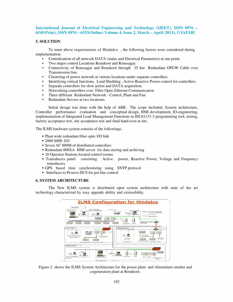
5. SOLUTION
To meet above requirements of Hindalco , the following factors were considered during implementation.
• Centralization of all network DATA (status and Electrical Parameters) at one point. • Two major control Locations Renukoot and Renusagar. • Connectivity of Renusagar and Renukoot through 35 km Redundant OPGW Cable over
Transmission line. • Clustering of power network at various locations under separate controllers. • Identifying critical functions, Load Shedding , Active Reactive Power control for controllers. • Separate controllers for slow action and DATA acquisition. • Networking controllers over Fiber Optic Ethernet Communication • Three different Redundant Network - Control ,Plant and Fast • Redundant Servers at two locations.
Initial design was done with the help of ABB . The scope included; System architecture, Controller performance evaluation and conceptual design, HMI development, IO-engineering, implementation of Integrated Load Management Functions in IEC61131-3 programming tool, testing, factory acceptance test, site acceptance test and final hand-over at site.
The ILMS hardware system consists of the followings:
• Plant wide redundant fiber optic I/O link • 2000 S800 -I/O • Seven AC 800M of distributed controllers • Redundant 800XA HMI server for data storing and archiving • 10 Operator Stations located control rooms • Transducers panel consisting Active power, Reactive Power, Voltage and Frequency
transducers. • GPS based time synchronizing using SNTP protocol • Interfaces to Process DCS for pot line control.
6. SYSTEM ARCHITECTURE
The New ILMS system is distributed open system architecture with state of the art technology characterized by easy upgrade ability and extensibility.
Figure-2 shows the ILMS System Architecture for the power plant and Aluminium smelter and cogeneration plant at Renukoot.
International Journal of Electrical Engineering and Technology (IJEET), ISSN 0976 –
6545(Print), ISSN 0976 – 6553(Online) Volume 4, Issue 2, March – April (2013), © IAEME
193
Major components of ILMS are as follows: I. Remote Terminal Unit with AC800
High-end process computers of type Advant Controller AC800M with S800 stations, which function as Remote Terminal Unit (RTU), and configured along with application software. All the ILMS application software must reside in this controller.
II. Remote Terminal Unit with S800 Station (RTU)
Data collection for each S800 Station is achieved using S800 type I/O cards. These cards are of type AI/DI/DO/AO for Analog inputs, Digital inputs, Digital outputs and analog outputs respectively.
III. ABB REF Relays
Fast switching relays with configurable outputs. The relay used for detecting under frequency condition and to initiates tripping of loads.
IV. HMI Server
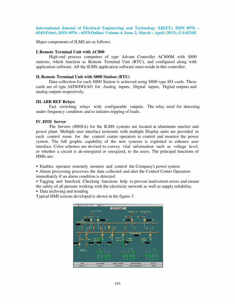
The Servers (800XA) for the ILMS systems are located at aluminum smelter and power plant. Multiple user interface terminals with multiple Display units are provided in each control room for the control center operators to control and monitor the power system. The full graphic capability of the new systems is exploited to enhance user interface. Color schemes are devised to convey vital information such as voltage level, or whether a circuit is de-energized or energized, to the users. The principal functions of HMIs are: • Enables operator remotely monitor and control the Company's power system • Alarm processing processes the data collected and alert the Control Center Operators immediately if an alarm condition is detected. • Tagging and Interlock Checking functions help to prevent inadvertent errors and ensure the safety of all persons working with the electricity network as well as supply reliability. • Data archiving and trending Typical HMI screens developed is shown in the figure-3

International Journal of Electrical Engineering and Technology (IJEET), ISSN 0976 –
6545(Print), ISSN 0976 – 6553(Online) Volume 4, Issue 2, March – April (2013), © IAEME
194
6.1 Software integration
The system has Load shedding, Generator shedding and Load management module to meet entire requirements Hindalco. The total implementation comes under system protection scheme. Initiation of control actions will be managed by the contingency manager which will identify the contingencies and initiates one or more modules to operate automatically. Below section will give details of modules implemented.
6.2 Load shedding schemes
Disturbances in the power balance that require load shedding [5] are usually caused by loss of generated power or network change. The loss is in almost every case caused by the trip of a (critical-) circuit breaker and disconnecting generation from the load. Fast Load shedding (FLS) initiates power balance calculations on the trip of a critical breaker. The module calculates the load to be shed and compared to the priority load table. FLS function will issue shed commands to all loads with the lowest priority and the calculated priority. Load shedding can be defined as the amount of load required to be disconnected from a system to keep that system within satisfactory operational limits[1].
Based on the status of tiebreaker / bus couplers there can be a different number of electrical networks that work independently. FLS will make the calculation for each individual electrical network that contains a load busbar (a busbar to which generation and loads are connected). Load shedding Feeder priorities can be done on line and FLS can handle up to 50 priorities. Each load can be temporarily inhibited from the load shedding system. In the Figure-4 shows the blocking during critical condition.
Figure-4 Blocking During Critical Conditions
6.3 Under frequency load shed schemes
A low frequency is an indication for reaching the limit of the power generation. This may occur when the total load in the electrical network is a little higher than the generation and no spinning reserve is left. This situation may not directly lead to trips of breakers but when the frequency drops beneath a level, which is detected by frequency relays, under Frequency Load shedding (UFLS) [5] will shed the loads, which are assigned to trip on activation of the frequency relay. The amount of load to be shed is calculated as percentage of total load defined by the operator against each under frequency stage. After calculating load to be shed, program determines the priorities of feeders to be tripped. Trip commands must be issued to feeders whose load shed priority is less than or equal to the calculated priority to be shed.

International Journal of Electrical Engineering and Technology (IJEET), ISSN 0976 –
6545(Print), ISSN 0976 – 6553(Online) Volume 4, Issue 2, March – April (2013), © IAEME
195
6.4 Generator shedding
When the system operated is islanded mode, then the sudden loss of the bulk loads will cause over frequency in the network, the situation is also called “load throw”. Loss of generation from the power plant and load throw from smelter have been shown in figure 5 and 6.
Figure-5 Loss of Generation from Power Plant
Figure -6 Renukoot Load Throw
If this load throw is more than that of single generator unit then it can cause cascaded tripping of generators units in the system. To avoid such contingency, ILMS monitors power imbalance and breaker disconnect status of loads and issues generator trip to stabilize the system [6]. ILMS uses reverse logics of load shedding to achieve the generator shedding. Assignment of priorities can be done online and can handle up to 20 priorities. Each load can be temporarily inhibited from the generator shedding system.
International Journal of Electrical Engineering and Technology (IJEET), ISSN 0976 –
6545(Print), ISSN 0976 – 6553(Online) Volume 4, Issue 2, March – April (2013), © IAEME
196
rD
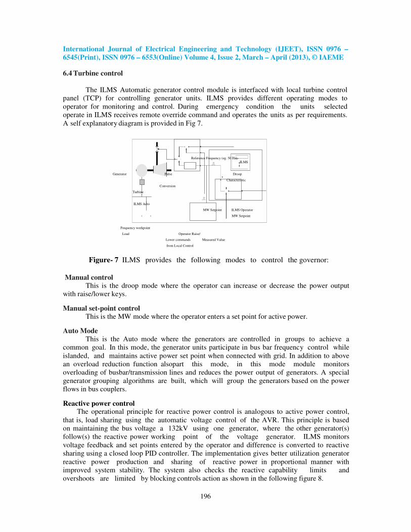
6.4 Turbine control
The ILMS Automatic generator control module is interfaced with local turbine control panel (TCP) for controlling generator units. ILMS provides different operating modes to operator for monitoring and control. During emergency condition the units selected operate in ILMS receives remote override command and operates the units as per requirements. A self explanatory diagram is provided in Fig 7.
Reference Frequency (eg. 50 Hz) ILMS
Generator Pulse Droop
Characteristic
Conversion
Turbine
ILMS Auto
MW Setpoint ILMS Operator
MW Setpoint
Frequency workpoint
Load Operator Raise/
Lower commands Measured Value
from Local Control
Figure- 7 ILMS provides the following modes to control the governor:
Manual control This is the droop mode where the operator can increase or decrease the power output
with raise/lower keys.
Manual set-point control This is the MW mode where the operator enters a set point for active power.
Auto Mode
This is the Auto mode where the generators are controlled in groups to achieve a common goal. In this mode, the generator units participate in bus bar frequency control while islanded, and maintains active power set point when connected with grid. In addition to above an overload reduction function alsopart this mode, in this mode module monitors overloading of busbar/transmission lines and reduces the power output of generators. A special generator grouping algorithms are built, which will group the generators based on the power flows in bus couplers.
Reactive power control The operational principle for reactive power control is analogous to active power control,
that is, load sharing using the automatic voltage control of the AVR. This principle is based on maintaining the bus voltage a 132kV using one generator, where the other generator(s) follow(s) the reactive power working point of the voltage generator. ILMS monitors voltage feedback and set points entered by the operator and difference is converted to reactive sharing using a closed loop PID controller. The implementation gives better utilization generator reactive power production and sharing of reactive power in proportional manner with improved system stability. The system also checks the reactive capability limits and overshoots are limited by blocking controls action as shown in the following figure 8.

International Journal of Electrical Engineering and Technology (IJEET), ISSN 0976 –
6545(Print), ISSN 0976 – 6553(Online) Volume 4, Issue 2, March – April (2013), © IAEME
197
Figure-8 Reactive Control and Synchronization
Load control During critical situation increasing power output of generators are limited due to
process constraints. So ILMS will control pot lines and reduces the power requirements instead of overloading generators [7]. ILMS monitors import set points, maximum demands and frequencies and gives tap lower or lower set points to pot lines.
Typical for Pot-lines 1,2 and 3 132 kV Voltage Level Main Trafo (T1) (132/1.5 kV)
Pot-line in ILMS Control
11.5 kV Voltage Level Measured Active Power Regulating Trafo [R1] (11.5 kV/730 V) ILMS Control Setpoint calculated by ILMS Manual/Auto 730V Voltage level Measured Current (for Auto Control) 800V DC Pot-line Feeders
Figure 9 : ILMS Control s for POT lines

International Journal of Electrical Engineering and Technology (IJEET), ISSN 0976 –
6545(Print), ISSN 0976 – 6553(Online) Volume 4, Issue 2, March – April (2013), © IAEME
198
7. UTILIZING SCADA FOR GRID SYNCHRONIZATION
SCADA brings HIL Network Frequency to match SCADA set point and Voltage Equalization is done Manually.
Figure 10 Utilizing SCADA for GRID Synchronization
Synchronization is finally done by Synch Check Relay and Synchronoscope. Figure – 11 and 12 shows the lowering generation or Load by slow action.
Figure-11 Lowering Generation or Load By Slow Action

International Journal of Electrical Engineering and Technology (IJEET), ISSN 0976 –
6545(Print), ISSN 0976 – 6553(Online) Volume 4, Issue 2, March – April (2013), © IAEME
199
Figure -12 Lowering Generation or Load By Slow Action
8. CASE STUDIES : TUNING USING DISTURBANCE FAULT RECORDER (DFR)
The objective of case studies is to study the suitability of ILMS and SCADA for
Hindalco smelter.Two case studies were carried out for particular parameters and found their performance satisfactory. Case Study 1: Tuning SCADA to distinguish Power Swing from Grid Violation:- Power swing is a variation in three-phase power flow which occurs when the generator angles are advancing or retarding relative to each other in response to changes in load magnitudes and direction, line switching, loss of generation, faults, and other system disturbances. A standalone DFR system was installed to monitor critical parameters and important points on the network. Both SCADA and DFR are GPS synchronized. Typical SCADA action are reviewed with recorded waveforms from DFR. Response of critical transducers are cross checked. Tuning Soft Controller to match response of Transducer. Fine tuning Soft Timers as network response time and time delay acquiring binary status. Major Disturbance are scrutinized by comparing both Data. Logic Modification if required.

International Journal of Electrical Engineering and Technology (IJEET), ISSN 0976 –
6545(Print), ISSN 0976 – 6553(Online) Volume 4, Issue 2, March – April (2013), © IAEME
200
Figure 13 Time Delay and Logic Requires Modification to distinguish between power swings and grid Violation
Case Study 2: Logic Modification to detect Isolation from Grid End was carried out . A
new Logic was developed to detect zero power flow on grid lines and simulation of tripping of Hindalco side breaker was carried out on above condition and it was established that SCADA now recognizes the islanded conditions.
Figure – 14 DFR data analysis

International Journal of Electrical Engineering and Technology (IJEET), ISSN 0976 –
6545(Print), ISSN 0976 – 6553(Online) Volume 4, Issue 2, March – April (2013), © IAEME
201
9. CONCLUSIONS
With the implementation of ILMS in December 2007, The smelter and Alumina refinary have successfully sustained major outage conditions. Implementation of ILMS with SCADA system together with a reliable fiber optic communications system controls and monitors the plant for any contingencies. As ILMS implemented with automatic real time trigger detection, load shedding and generation shedding protects the plant under different contingencies. . The ILMS is not having any financial or plant efficiency constraints while load managing application. At Hindalco, in plant generation, critical loads, insufficient reliability of grid supply , the typical power management functionality with the help of intelligent load management system along with SCADA ensures fast load shedding at any time as well as power to all critical loads in the plant and switching off non-essential load in case of shortage of power in the plant with a typical response time less than 100 ms. This research article has demonstrated the load shedding scheme with a computerized power management system to provide fast and optimum load management with actual operating conditions at Hindalco smelter. ACKNOWLEDGEMENT
Author acknowledges HINDALCO Industry and M/S ABB Ltd. for supporting and
giving permission to carry out the work. He is also thankful to Mr. K. N. Pandey for his suggestions to improve the article. REFERENCES [1] F Shokooh, JJ Dai, S Shokooh, J Tastet, H Castro, T Khandelwal and G Donner, “Intelligent Load Shedding” IEEE Industrial Application Magzene Vol. 17,pp. 44-53, 2011. [2] JL Aguero, M Beroqui and S Achilles “Aluminum Plant. Load Modeling for Stability Studies” IEEE Power Engineering Society Summer Meeting. Pp.1330-1335, 1999. [3] A Molina, A GabaldÓn, F Faura and JA Fuentes “New Approaches to Model Electric Demand in Aluminium Smelter Industr” IEEE Industry Applications Conf. pp.1426-1431, 2001. [4] T Wilson “PLC Based Substation Automation and SCADA Systems; Selecting a Control System Integrator”, Western Electric Power Institute, 1999. [5] WC New “Load Shedding, Load Restoration and Generator Protection Using Solid State and Electromechanical Underfrequency Relays” General Electric Company Philadelphia, 1983. [6] E Kimbark “Power System Stablity” Wiley IEEE, 1995. [7] J Kennedy, P Ciufo , A Agalgaonkar “Intelligent load management in microgrids” IEEE Power and Energy Society General Meeting 2, 2012. [8] M.S.Sujatha and Dr M. Vijay Kumar, “Under Frequency Load Shedding for Energy Management Using ANFIS/Case Study”, International Journal of Electrical Engineering & Technology (IJEET), Volume 4, Issue 2, 2013, pp. 93 - 104, ISSN Print : 0976-6545, ISSN Online: 0976-6553. [9] Mukesh Kumar Kirar and Ganga Agnihotri, “Transient Stability Enhancement by Ann Based Adaptive Load Shedding”, International Journal of Electrical Engineering & Technology (IJEET), Volume 3, Issue 3, 2012, pp. 200 - 210, ISSN Print : 0976-6545, ISSN Online: 0976-6553.