Embed Size (px)
Citation preview

http://jer.sagepub.com/International Journal of Engine Research
http://jer.sagepub.com/content/3/3/127The online version of this article can be found at:
DOI: 10.1243/14680870260189253
2002 3: 127International Journal of Engine ResearchN Karamanis and R. F. Martinez-Botas
Mixed-flow turbines for automotive turbochargers: Steady and unsteady performance
Published by:
http://www.sagepublications.com
On behalf of:
Institution of Mechanical Engineers
can be found at:International Journal of Engine ResearchAdditional services and information for
http://jer.sagepub.com/cgi/alertsEmail Alerts:
http://jer.sagepub.com/subscriptionsSubscriptions:
http://www.sagepub.com/journalsReprints.navReprints:
http://www.sagepub.com/journalsPermissions.navPermissions:
http://jer.sagepub.com/content/3/3/127.refs.htmlCitations:
What is This?
- Jun 1, 2002Version of Record >>
at IMECHE on May 25, 2014jer.sagepub.comDownloaded from at IMECHE on May 25, 2014jer.sagepub.comDownloaded from

Mixed-flow turbines for automotiveturbochargers: steady and unsteadyperformance
N Karamanis and R F Martinez-Botas
Department of Mechanical Engineering, Imperial
College of Science, Technology and Medicine,
London, UK
Received 16 May 2002
Abstract: Turbochargers are finding increasing appli- increasingly more stringent emission standards. This
cation to automotive diesel engines as cost effective means paper is part of an extensive experimental pro-
for improving their power output and efficiency, and gramme focused on turbine design technology for
reducing exhaust emissions; these requirements have led vehicle applications aiming to (a) explore available
to the need for highly loaded turbocharger turbines. A means to modify the turbine operating characteristics
mixed-flow turbine is capable of achieving its peak isen- in order to improve the engine/turbocharger match-
tropic efficiency at reduced velocity ratios compared to a ing and (b) improve the transfer of energy from the
typical radial inflow turbine; it is therefore possible to pulsating exhaust gases to the turbine. In order to
improve the turbocharger/engine matching. These turbines achieve these aims, the project is centred on mixed-
differ from the commonly used radial turbines in that the flow turbine rotors as opposed to radial rotors com-
flow approaches the rotor in the non-radial direction; in monly used in automotive turbochargers. This choice
the extreme a mixed-flow turbine would become an axial overcomes one of the principal limitations of the
machine. The steady and unsteady performances of a radial inflow turbine, where stress and material con-
mixed-flow turbocharger turbine with a constant blade siderations dictate that the blade angle must be zero
inlet angle have been investigated. The steady flow results to maintain radial blade sections and to keep the
indicated that the mixed-flow turbine obtains a peak centrifugal load in the blades purely tensile. A
efficiency (total-to-static) of 75 per cent at a velocity ratio mixed-flow geometry permits the use of a non-zero
of 0.61, compared with that of a typical radial-inflow tur- blade angle without departure from the above
bine which peaks at a velocity ratio of 0.7. The performance requirement and introduces an extra degree of free-
and flow characteristics were found to deviate significantly dom into the rotor design, which has particular
from the equivalent steady state values commonly used in implications for the range of operation of the turbine,
turbocharger turbine design. the incidence losses associated with the fluid
entering the rotor and the development of the flow
Key words: aerodynamics, turbomachinery, mixed-flow within the rotor passage.
turbines, turbocharger Figure 1a shows a schematic diagram of a mixed-
flow turbine together with a photograph of the rotor
(Fig. 1b). The idea of a mixed-flow turbine is not
1. Introduction entirely new and such developments have been
described elsewhere [1 ± 4]. However, limited con-
sideration has been given to the potential for mod-Turbochargers are widely applied to diesel engines
in order to improve their power output and ifying the turbine characteristics to improve engine
matching.efficiency, and reduce exhaust emissions. Existing
turbocharging systems for automotive diesel engines The turbine requirement in highly loaded turbo-
charged diesel engines is that its peak efficiency mustmust be reconsidered in order to meet the require-
ments of better fuel economy and the need to satisfy reach maximum at low velocity ratios (i.e. low U/Cis ,
127Int J Engine Research Vol 3 No 3JER 01302 © 2002 IMechE
at IMECHE on May 25, 2014jer.sagepub.comDownloaded from

N Karamanis and R F Martinez-Botas
Fig. 1 Mixed-flow turbine geometry.
where Cis is the velocity that would be attained if the ditions to the rotor (Fig. 1a). Thus, the flow enters
the rotor at an angle in between the axial andworking fluid were expanded in an ideal nozzle over
radial directions and exits in the axial direction. Athe same pressure ratio as that of the turbine). The
direct comparison between a mixed-flow and itsreason for this is twofold:
radial-inflow counterpart leads to the following
considerations:1. The turbine rotor is influenced by the size,
geometry and clearance of its casing. High air± fuel1. Fuel consumption. The potential of the mixed-ratios together with the use of an intercooler
flow rotor to improve engine fuel consumption,between the compressor and the engine result inin comparison to an equivalent radial-inflowa lower exhaust temperature and, hence, lowerrotor, was addressed in reference [2].
energy and a higher density. The turbine must2. Engine/turbocharger matching. The mixed-flow
extract sufficient power from this low-energyturbine rotor can operate at its maximum
engine exhaust to drive the compressor in orderefficiency in a wide range of air flow and pressure
to achieve high boost pressures. This is only poss-ratios. The steady flow and unsteady flow per-
ible with a smaller turbine running at a suffic-formance tests of a mixed flow turbine in the
iently high rotational speed. The turbine speed ispresent paper will demonstrate the operating
limited by stresses and so a large expansion ratioflexibility of the proposed design.
is required, which in turn results in low velocity3. Design. The mixed-flow configuration overcomes
ratios (U/Cis). the zero-blade limitation. The blades are radial in2. The size and volume of the exhaust manifold of
any section cut normal to the rotational axis; i.e.an automotive engine is limited due to the need
the projection of the mean blade surface on a refer-for a high power± weight ratio and compact instal-
ence cylinder is a unique curve.lation, which implies that the exhaust pulsations
4. Size. The proposed design reduces significantlyare largely undamped at the turbine inlet. The
the flow path curvature and distance. This meansbehaviour of radial-inflow turbines under pulsat-
that the incoming gas flows smoothly within aing flow conditions has revealed that the maxi-
shorter blade passage with less flow separation.mum energy in the exhaust is available at high Thus the detrimental effect of aerodynamic block-exhaust manifold pressures [5, 6]. Therefore, as age is improved substantially [4]. In consequence,the pressure ratio across the turbine increases the the turbine overall aerodynamic efficiency can beisentropic velocity increases, leading to the need improved.to achieve maximum turbine efficiency at low 5. Velocity ratio. The mixed-flow design meets theU/Cis . requirement of achieving a peak efficiency at a
velocity ratio lower than a radial turbine. This canThe mixed-flow rotor goes some way to meeting be seen by considering the following equation:
the afore-mentioned requirements 1 and 2. It differs
from its radial counterpart in the forward sweep of U2
Cis
=1
2S1 tan bB
tan a 2the leading edge, resulting in non-radial inlet con-
128 Int J Engine Research Vol 3 No 3JER 01302 © 2002 IMechE
at IMECHE on May 25, 2014jer.sagepub.comDownloaded from
Mixed-flow turbines for automotive turbochargers
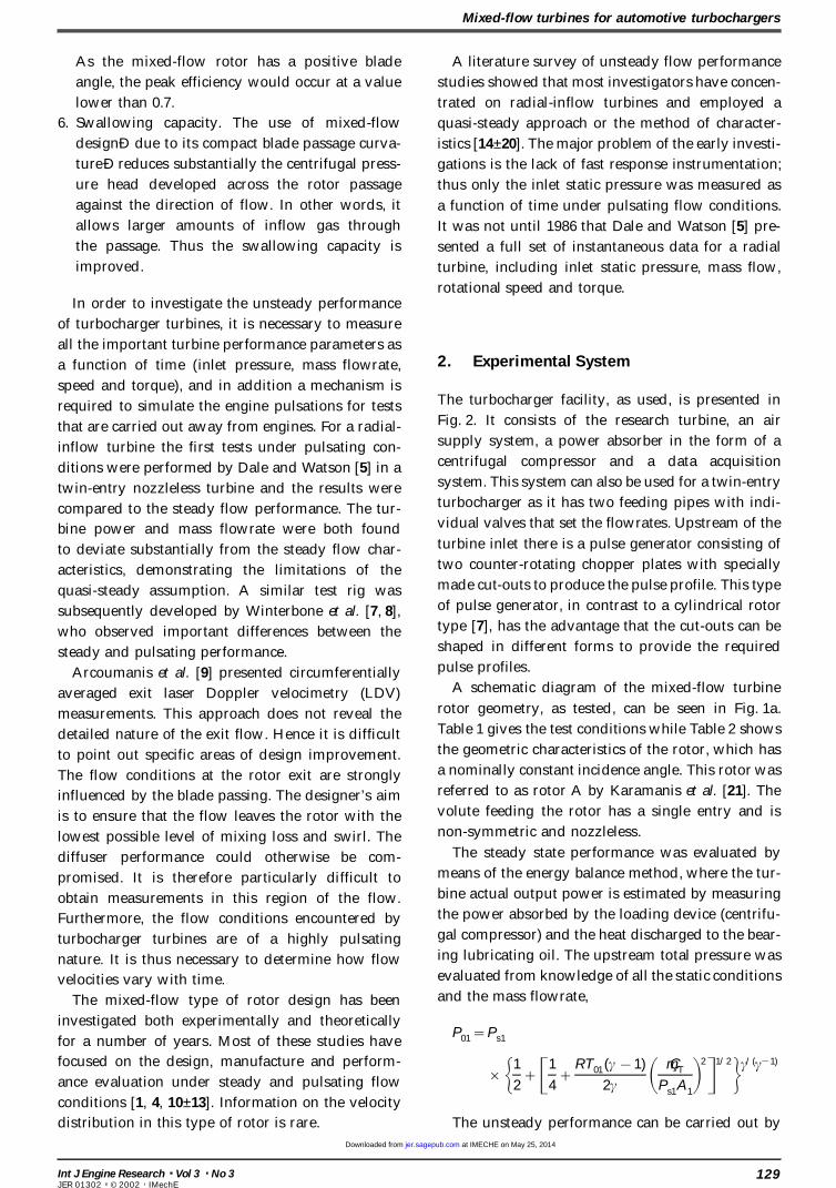
As the mixed-flow rotor has a positive blade A literature survey of unsteady flow performance
angle, the peak efficiency would occur at a value studies showed that most investigators have concen-
lower than 0.7. trated on radial-inflow turbines and employed a
6. Swallowing capacity. The use of mixed-flow quasi-steady approach or the method of character-
designÐ due to its compact blade passage curva- istics [14 ± 20]. The major problem of the early investi-
ture Ð reduces substantially the centrifugal press- gations is the lack of fast response instrumentation;
ure head developed across the rotor passage thus only the inlet static pressure was measured as
against the direction of flow. In other words, it a function of time under pulsating flow conditions.
allows larger amounts of inflow gas through It was not until 1986 that Dale and Watson [5] pre-
the passage. Thus the swallowing capacity is sented a full set of instantaneous data for a radial
improved. turbine, including inlet static pressure, mass flow,
rotational speed and torque.In order to investigate the unsteady performance
of turbocharger turbines, it is necessary to measure
all the important turbine performance parameters as2. Experimental Systema function of time (inlet pressure, mass flowrate,
speed and torque), and in addition a mechanism isThe turbocharger facility, as used, is presented inrequired to simulate the engine pulsations for testsFig. 2. It consists of the research turbine, an airthat are carried out away from engines. For a radial-supply system, a power absorber in the form of ainflow turbine the first tests under pulsating con-centrifugal compressor and a data acquisitionditions were performed by Dale and Watson [5] in asystem. This system can also be used for a twin-entrytwin-entry nozzleless turbine and the results wereturbocharger as it has two feeding pipes with indi-compared to the steady flow performance. The tur-vidual valves that set the flowrates. Upstream of thebine power and mass flowrate were both foundturbine inlet there is a pulse generator consisting ofto deviate substantially from the steady flow char-two counter-rotating chopper plates with speciallyacteristics, demonstrating the limitations of themade cut-outs to produce the pulse profile. This typequasi-steady assumption. A similar test rig wasof pulse generator, in contrast to a cylindrical rotorsubsequently developed by Winterbone et al. [7, 8],type [7], has the advantage that the cut-outs can bewho observed important differences between theshaped in different forms to provide the requiredsteady and pulsating performance.pulse profiles.Arcoumanis et al. [9] presented circumferentially
A schematic diagram of the mixed-flow turbineaveraged exit laser Doppler velocimetry (LDV)rotor geometry, as tested, can be seen in Fig. 1a.measurements. This approach does not reveal theTable 1 gives the test conditions while Table 2 showsdetailed nature of the exit flow. Hence it is difficultthe geometric characteristics of the rotor, which hasto point out specific areas of design improvement.a nominally constant incidence angle. This rotor wasThe flow conditions at the rotor exit are stronglyreferred to as rotor A by Karamanis et al. [21]. Theinfluenced by the blade passing. The designer’s aimvolute feeding the rotor has a single entry and isis to ensure that the flow leaves the rotor with thenon-symmetric and nozzleless.lowest possible level of mixing loss and swirl. The
The steady state performance was evaluated bydiffuser performance could otherwise be com-means of the energy balance method, where the tur-promised. It is therefore particularly difficult tobine actual output power is estimated by measuringobtain measurements in this region of the flow.the power absorbed by the loading device (centrifu-Furthermore, the flow conditions encountered bygal compressor) and the heat discharged to the bear-turbocharger turbines are of a highly pulsatinging lubricating oil. The upstream total pressure wasnature. It is thus necessary to determine how flowevaluated from knowledge of all the static conditionsvelocities vary with time.and the mass flowrate,The mixed-flow type of rotor design has been
investigated both experimentally and theoreticallyP01=Ps1for a number of years. Most of these studies have
focused on the design, manufacture and perform-×G1
2+C1
4+
RT01(c 1)
2c A mÇ T
Ps1A1B2D1/2Hc/(c 1)
ance evaluation under steady and pulsating flow
conditions [1, 4, 10 ± 13]. Information on the velocity
distribution in this type of rotor is rare. The unsteady performance can be carried out by
129Int J Engine Research Vol 3 No 3JER 01302 © 2002 IMechE
at IMECHE on May 25, 2014jer.sagepub.comDownloaded from

N Karamanis and R F Martinez-Botas
Fig. 2 Unsteady turbocharger test facility.
(b) turbine inlet and exit instantaneous pressure,Design Test (c) instantaneous mass flowrate, (d) instantaneous
Parameter conditions conditionsspeed, (e) time-averaged turboshaft speed, (f ) polar
Inlet total temperature (K) 923 344 moment of inertia of rotating components andMass flowrate (kg/s) 0.414 0.678 (g) pulse frequency.Rotational speed (r/min) 98 000 59 828Pressure ratio 2.91 2.91Velocity ratio 0.616 0.616
3. Results and DiscussionTable 1 Test conditions at 100 per cent speed.
3.1 Steady flow performance
The steady state performance of the mixed-flow rotorRotor tip mean diameter (mm) 83.58
was investigated at five different rotational speeds,Rotor inlet blade height (mm) 18Number of blades 12 covering a range from 50 to 90 per cent equivalentExducer tip diameter (mm) 78.6
design speeds. The total-to-static efficiency and theExducer hub diameter (mm) 27Blade angle at exducer root mean (deg) 52 swallowing capacity are shown in Fig. 3.
The total-to-static efficiency increases withTable 2 Mixed-flow rotor geometry. rotational speed up to the 80 per cent condition, after
which it remains nearly constant. The total-to-staticevaluating the following equation:
peak efficiency value (0.75 at 80 per cent speed)
occurs at a velocity ratio (U/Cis) of 0.61; this is in(gt-s)unsteady=
(WÇ T)inst
mÇ instC2is/2
(1) contrast to the well-known result, for radial-inflow
turbines, where the peak efficiency occurs at a 0.7where Cis is the isentropic expansion velocity at any velocity ratio [5]. This feature of shifting turbine peakinstant of time during the pulse cycle. It is defined efficiency towards lower velocity ratios increases theaccording to the following equation (variable prop- turbine overall efficiency in the low-velocity ratioerties have been taken into account as seen by the region, which confirms that the mixed-flow turbineintegral of C
pover the temperature range): can utilize the engine exhaust gas energy more effec-
tively than the radial-inflow turbine in the high-
Cis=S2 A P 1
3
Cp,T dT +1
2U2
1B (2) pressure ratio region. This will improve the turbine
unsteady performance, because most of the avail-
able exhaust gas energy occurs in the region of theand
pulse peak where the pressure ratio is high during(WÇ T)inst=tinstvinst (3)
the pulse cycle. As a result, the actual power output
of the mixed-flow turbine is larger than that ofHence the following quantities must be measured:
(a) time-averaged turbine inlet temperature, an equivalent radial-inflow turbine, which leads
130 Int J Engine Research Vol 3 No 3JER 01302 © 2002 IMechE
at IMECHE on May 25, 2014jer.sagepub.comDownloaded from

Mixed-flow turbines for automotive turbochargers
Fig. 3 Performance parameters for the mixed-flow rotor under steady flow conditions.
to an increased boost pressure produced by the tively flat. Hence, during a typical engine pulse, the
turbine efficiency does not change significantly whencompressor.
It is worth noting that the design of the inlet blade the turbine operating point moves from high to low
velocity ratios or vice versa. Assuming quasi-steadyangle of the mixed-flow turbine rotor was based on
the assumptions of a free vortex flow in the volute operation, this indicates that the unsteady flow per-
formance of the mixed-flow turbine is improved dueand a uniform distribution of the meridional velocity
along the blade leading edge. Neither of these to the increased turbine efficiencies at off-peak
efficiency conditions.assumptions is expected to be met in reality.
It is apparent that the operating behaviour of
increasing efficiencies at lower rotational speeds and 3.2 Unsteady flow performance
In order to improve the understanding of the behav-slightly decreasing efficiencies at higher rotational
speeds results in compact efficiency curves. This iour of mixed-flow turbines unsteady flow perform-
ance tests were performed. The unsteady flowfeature implies that a reduced sensitivity to the
rotational speed has been achieved. As a result, this performance tests were carried out at the peak
efficiency point of 50 and 70 per cent equivalentis expected to improve the transient performance of
the turbine since a change in the rotational speed design speed that corresponds to 29 400 and
41 300 r/min respectively. In addition, two air pulsewill produce a small change in efficiency levels. It is
also evident that the efficiency curve with respect to frequencies of 40 and 60 Hz were used to simulate
the pressure pulse of the engine exhaust gas. Thethe velocity ratio for a given rotational speed is rela-
131Int J Engine Research Vol 3 No 3JER 01302 © 2002 IMechE
at IMECHE on May 25, 2014jer.sagepub.comDownloaded from
N Karamanis and R F Martinez-Botas
pulse frequencies are produced by the pulse gener- ible and have been used by a number of researchers.
One is to assume that the turbine inlet total tempera-ator and are equivalent to the engine speeds of 1600
and 2400 r/min respectively, based on a four-stroke, ture remains constant during the pulse cycle. As a
result, the time-averaged static temperature, as meas-six-cylinder diesel engine with a single-entry turbine.
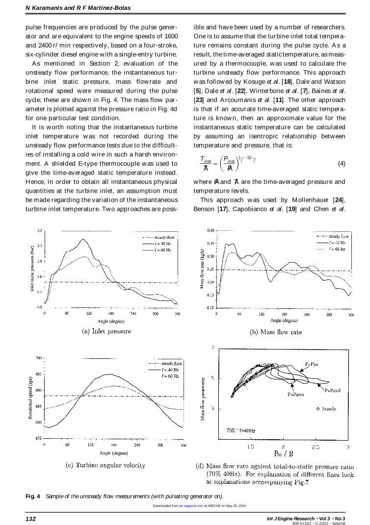
As mentioned in Section 2, evaluation of the ured by a thermocouple, was used to calculate the
turbine unsteady flow performance. This approachunsteady flow performance, the instantaneous tur-
bine inlet static pressure, mass flowrate and was followed by Kosuge et al. [18], Dale and Watson
[5], Dale et al. [22], Winterbone et al. [7], Baines et al.rotational speed were measured during the pulse
cycle; these are shown in Fig. 4. The mass flow par- [23] and Arcoumanis et al. [11]. The other approach
is that if an accurate time-averaged static tempera-ameter is plotted against the pressure ratio in Fig. 4d
for one particular test condition. ture is known, then an approximate value for the
instantaneous static temperature can be calculatedIt is worth noting that the instantaneous turbine
inlet temperature was not recorded during the by assuming an isentropic relationship between
temperature and pressure, that is:unsteady flow performance tests due to the difficult-
ies of installing a cold wire in such a harsh environ-Tinst
TÅ= APinst
PÅ B(c 1)/c(4)ment. A shielded E-type thermocouple was used to
give the time-averaged static temperature instead.
Hence, in order to obtain all instantaneous physical where PÅ and TÅ are the time-averaged pressure and
temperature levels.quantities at the turbine inlet, an assumption must
be made regarding the variation of the instantaneous This approach was used by Mollenhauer [24],
Benson [17], Capobianco et al. [19] and Chen et al.turbine inlet temperature. Two approaches are poss-
Fig. 4 Sample of the unsteady flow measurements (with pulsating generator on).
132 Int J Engine Research Vol 3 No 3JER 01302 © 2002 IMechE
at IMECHE on May 25, 2014jer.sagepub.comDownloaded from
Mixed-flow turbines for automotive turbochargers
[12]. Mollenhauer [24] pointed out that the instan- suggested by Dale and Watson [5], which assumes
that the travelling time corresponds to the propa-taneous exhaust gas energy obtained from the calcu-
lated instantaneous static temperature [equation (4)] gation time of a pressure wave from the measuring
plane to the turbine rotor passage. The presenthas small deviations from the true one obtained from
the measured instantaneous static temperature for authors measured the static pressure development
from the inlet measuring plane to the rotor inlet; thiswhich the mean error was only 1.3 per cent in his
tests. In the present paper the isentropic approach allowed the evaluation of the actual travel time of a
pressure pulse. The instantaneous pressure is meas-has been used.
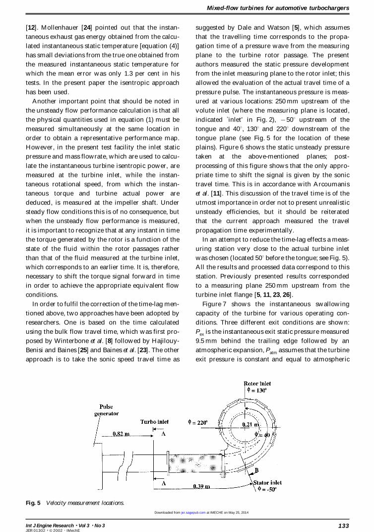
Another important point that should be noted in ured at various locations: 250 mm upstream of the
volute inlet (where the measuring plane is located,the unsteady flow performance calculation is that all
the physical quantities used in equation (1) must be indicated inlet’ in Fig. 2), 50° upstream of the
tongue and 40°, 130° and 220° downstream of themeasured simultaneously at the same location in
order to obtain a representative performance map. tongue plane (see Fig. 5 for the location of these
plains). Figure 6 shows the static unsteady pressureHowever, in the present test facility the inlet static
pressure and mass flowrate, which are used to calcu- taken at the above-mentioned planes; post-
processing of this figure shows that the only appro-late the instantaneous turbine isentropic power, are
measured at the turbine inlet, while the instan- priate time to shift the signal is given by the sonic
travel time. This is in accordance with Arcoumanistaneous rotational speed, from which the instan-
taneous torque and turbine actual power are et al. [11]. This discussion of the travel time is of the
utmost importance in order not to present unrealisticdeduced, is measured at the impeller shaft. Under
steady flow conditions this is of no consequence, but unsteady efficiencies, but it should be reiterated
that the current approach measured the travelwhen the unsteady flow performance is measured,
it is important to recognize that at any instant in time propagation time experimentally.
In an attempt to reduce the time-lag effects a meas-the torque generated by the rotor is a function of the
state of the fluid within the rotor passages rather uring station very close to the actual turbine inlet
was chosen (located 50° before the tongue; see Fig. 5).than that of the fluid measured at the turbine inlet,
which corresponds to an earlier time. It is, therefore, All the results and processed data correspond to this
station. Previously presented results correspondednecessary to shift the torque signal forward in time
in order to achieve the appropriate equivalent flow to a measuring plane 250 mm upstream from the
turbine inlet flange [5, 11, 23, 26].conditions.
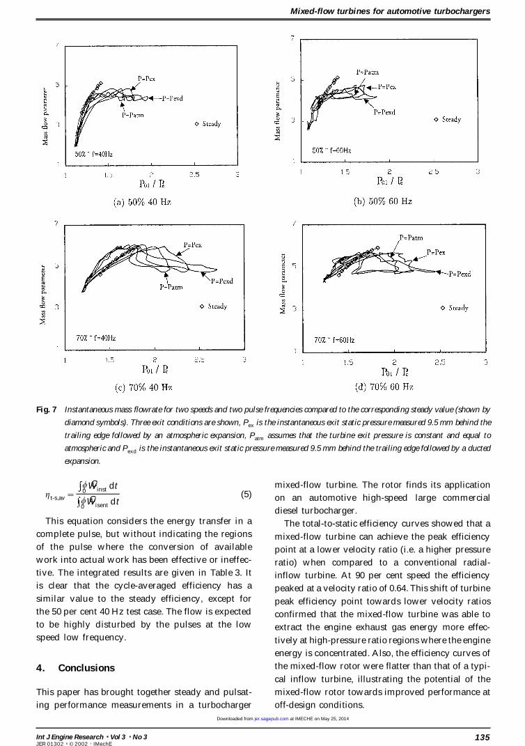
In order to fulfil the correction of the time-lag men- Figure 7 shows the instantaneous swallowing
capacity of the turbine for various operating con-tioned above, two approaches have been adopted by
researchers. One is based on the time calculated ditions. Three different exit conditions are shown:
Pex is the instantaneous exit static pressure measuredusing the bulk flow travel time, which was first pro-
posed by Winterbone et al. [8] followed by Hajilouy- 9.5 mm behind the trailing edge followed by an
atmospheric expansion, Patm assumes that the turbineBenisi and Baines [25] and Baines et al. [23]. The other
approach is to take the sonic speed travel time as exit pressure is constant and equal to atmospheric
Fig. 5 Velocity measurement locations.
133Int J Engine Research Vol 3 No 3JER 01302 © 2002 IMechE
at IMECHE on May 25, 2014jer.sagepub.comDownloaded from

N Karamanis and R F Martinez-Botas
Fig. 6 Instantaneous static pressure at different locations around the volute and exit. Inlet refers to the location shown in Fig. 2, the
different angles are referenced to the volute tongue (Fig. 5) and the exit is either an atmospheric expansion (exit) or ducted
expansion (duct exit, as in real engine conditions).
and Pexd is the instantaneous exit static pressure As a result, the isentropic efficiency becomes greater
than unity during this short period. A similar behav-measured 9.5 mm behind the trailing edge followed
by a ducted expansion (similar to an exhaust diffuser iour has been observed by Winterbone et al. [7, 8]
and Baines et al. [23] in their studies of the radial-in a real engine). As can be seen in this figure, the
instantaneous mass flow parameter circles around inflow turbines. Had the bulk travel time been
used to shift the signal, the isentropic efficiencythe steady parameter. The reason for this behaviour
is that the turbine/volute acts as a finite volume, so would have been greater than one for most of the
pulsating period.as the pulse generator is opened it takes a certain
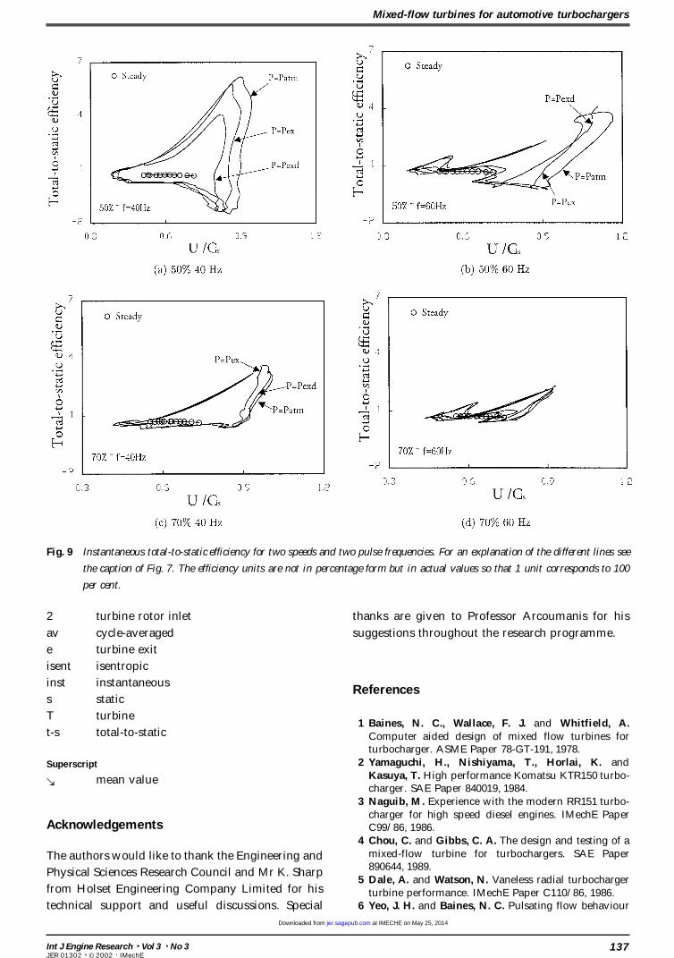
amount of time to fill up the volume; when the plate The traces of the instantaneous total-to-static
efficiency are shown in Fig. 9 as a function of veloc-is closing it does not have enough time to empty.
Figure 8 shows the performance parameters for one ity ratio for all pulsating flow conditions; they are
compared with the corresponding steady flowtesting condition (70 per cent and 40 Hz) as a sample
of the data. Three quantities are plotted: isentropic efficiency curves. The actual exit static pressure
was measured with a fast transducer. This valuepower, actual power and isentropic efficiency, all as
a function of pulse generator angle (this angle can coupled with the actual total pressure feeding the
turbine gives rise to the actual fluctuating pressurebe viewed as equivalent to time). It is worth noting
that the values of the unsteady efficiency in some ratio across the turbine. It is evident that the
unsteady efficiency curves deviate from the steadyregions are in excess of unity. The isentropic power
follows the trace of inlet static pressure since it is flow values. The range of the velocity ratio and the
total-to-static efficiency is reduced as the pulse fre-calculated from the instantaneous inlet pressure and
mass flowrate; the turbine actual power follows the quency is increased. Hence, the area enclosed by
the loop is reduced with the increasing pulse fre-trace of the fluctuating torque. These signals have
been shifted according to the sonic travel time, as quency. The use of the instantaneous pressure
leads to a reduction of the regions of efficiencyexplained previously. Before the pulse generator
goes into its open position, the inlet pressure and greater than unity as compared to a constant
atmospheric pressure expansion.mass flowrate reach their lowest values and result
in a minimum isentropic power. At the same time, In order to arrive at a single value of efficiency
independent of the time shift, the results have beenthe actual power in this initial stage of the pulse is
higher than the isentropic power due to the effect cycle-averaged over a complete pulse cycle. The
definition of this average efficiency is given by theof the rotational inertia of the turbine± compressor
assembly, which causes the rotor to act as a flywheel. following equation:
134 Int J Engine Research Vol 3 No 3JER 01302 © 2002 IMechE
at IMECHE on May 25, 2014jer.sagepub.comDownloaded from
Mixed-flow turbines for automotive turbochargers
Fig. 7 Instantaneous mass flowrate for two speeds and two pulse frequencies compared to the corresponding steady value (shown by
diamond symbols). Three exit conditions are shown, Pex is the instantaneous exit static pressure measured 9.5 mm behind the
trailing edge followed by an atmospheric expansion, Patm assumes that the turbine exit pressure is constant and equal to
atmospheric and Pexd is the instantaneous exit static pressure measured 9.5 mm behind the trailing edge followed by a ducted
expansion.
mixed-flow turbine. The rotor finds its applicationgt-s,av=
w0
WÇ inst dt
w0
WÇ isent dt(5) on an automotive high-speed large commercial
diesel turbocharger.This equation considers the energy transfer in a The total-to-static efficiency curves showed that a
complete pulse, but without indicating the regions mixed-flow turbine can achieve the peak efficiencyof the pulse where the conversion of available point at a lower velocity ratio (i.e. a higher pressurework into actual work has been effective or ineffec- ratio) when compared to a conventional radial-tive. The integrated results are given in Table 3. It inflow turbine. At 90 per cent speed the efficiencyis clear that the cycle-averaged efficiency has a peaked at a velocity ratio of 0.64. This shift of turbinesimilar value to the steady efficiency, except for peak efficiency point towards lower velocity ratiosthe 50 per cent 40 Hz test case. The flow is expected confirmed that the mixed-flow turbine was able toto be highly disturbed by the pulses at the low extract the engine exhaust gas energy more effec-speed low frequency. tively at high-pressure ratio regions where the engine
energy is concentrated. Also, the efficiency curves of
the mixed-flow rotor were flatter than that of a typi-4. Conclusionscal inflow turbine, illustrating the potential of the
mixed-flow rotor towards improved performance atThis paper has brought together steady and pulsat-
ing performance measurements in a turbocharger off-design conditions.
135Int J Engine Research Vol 3 No 3JER 01302 © 2002 IMechE
at IMECHE on May 25, 2014jer.sagepub.comDownloaded from

N Karamanis and R F Martinez-Botas
Fig. 8 Instantaneous actual work, isentropic work and efficiency for a typical test case (70%, 40 Hz). Note that the efficiency is not
in percentage form but in actual values so that 1 unit corresponds to 100 per cent.
responding steady flow curves, exhibiting a signifi-Condition Steady Unsteady cant hysteresis loop. This indicated that the turbine
performance and flow characteristics under pulsat-50% and 40 Hz 0.69 0.55
ing flow conditions deviated from the steady flow50% and 60 Hz 0.69 0.7370% and 40 Hz 0.74 0.74 results. As the air pulse frequency increased, the area70% and 60 Hz 0.74 0.77
enclosed by the loop was reduced, indicating that
the flow conditions within the turbine tend toTable 3 Unsteady cycle average efficiency.become closer to the steady values.
The unsteady performance of the mixed-flow tur-
bine has been assessed under pulsating flow con- Notationditions at the peak 50 and 70 per cent design speeds
at pulse frequencies of 40 and 60 Hz. Accurate A cross-sectional area
measurement of the instantaneous flow parameters Cis isentropic expansion velocity
(mass flowrate, static pressure, rotational speed) was Cp
specific heat capacity at constant pressure
mÇ mass flowrateimportant to obtain realistic efficiencies. The instan-
MFP mass flow parameter=mÇ T T01 /P01taneous inlet temperature was used in preference to
P pressureassuming a constant value. The effect of varying
PR pressure ratio=P01/Peexhaust conditions was also considered. Previous
t timeauthors on radial turbines have not considered the
T temperaturefluctuation of the exhaust pressure. It has been
U blade tip speed; air velocityshown that this has a very significant effect and
WÇ powerignoring it leads to estimation of unrealistic expan-
sion ratios. The use of the instantaneous exit pressurea absolute flow angle
leads to a reduction of instantaneous efficiencybB blade rotor inlet angle
values greater than unity.c ratio of specific heat capacities
The pulsation from the engine has been measuredg efficiency
throughout the inlet pipe and around the volute andt torque
its speed of propagation has been shown to be closew time corresponding to rotation
to the speed of sound rather than the bulk flow veloc-v rotational speed
ity as stated by some researchers. Thus, any correc-
tions in time shift have been based on the sonic Subscripts
speed. As a general remark, the unsteady swallowing 0 total or stagnation value
1 turbine volute inletcapacity and efficiency curves moved around the cor-
136 Int J Engine Research Vol 3 No 3JER 01302 © 2002 IMechE
at IMECHE on May 25, 2014jer.sagepub.comDownloaded from
Mixed-flow turbines for automotive turbochargers
Fig. 9 Instantaneous total-to-static efficiency for two speeds and two pulse frequencies. For an explanation of the different lines see
the caption of Fig. 7. The efficiency units are not in percentage form but in actual values so that 1 unit corresponds to 100
per cent.
2 turbine rotor inlet thanks are given to Professor Arcoumanis for his
suggestions throughout the research programme.av cycle-averaged
e turbine exit
isent isentropic
inst instantaneousReferences
s static
T turbine1 Baines, N. C., Wallace, F. J. and Whitfield, A.
t-s total-to-static Computer aided design of mixed flow turbines forturbocharger. ASME Paper 78-GT-191, 1978.
2 Yamaguchi, H., Nishiyama, T., Horlai, K. andSuperscriptKasuya, T. High performance Komatsu KTR150 turbo-: mean valuecharger. SAE Paper 840019, 1984.
3 Naguib, M. Experience with the modern RR151 turbo-charger for high speed diesel engines. IMechE Paper
Acknowledgements C99/86, 1986.4 Chou, C. and Gibbs, C. A. The design and testing of a
mixed-flow turbine for turbochargers. SAE PaperThe authors would like to thank the Engineering and890644, 1989.
Physical Sciences Research Council and Mr K. Sharp5 Dale, A. and Watson, N. Vaneless radial turbocharger
from Holset Engineering Company Limited for his turbine performance. IMechE Paper C110/86, 1986.6 Yeo, J. H. and Baines, N. C. Pulsating flow behaviourtechnical support and useful discussions. Special
137Int J Engine Research Vol 3 No 3JER 01302 © 2002 IMechE
at IMECHE on May 25, 2014jer.sagepub.comDownloaded from

N Karamanis and R F Martinez-Botas
in a twin-entry vaneless radial-inflow turbine. IMechE 16 Wallace, F. J. and Blair, G. P. The pulsating flow per-formance of inward radial flow turbines. ASME PaperPaper C405/004, 1990.
7 Winterbone, D. E., Nikpour, B. and Alexander, G. L. 65-GTP-21, 1965.17 Benson, R. S. Non-steady flow in a turbochargerMeasurement of the performance of a radial inflow tur-
bine in conditional steady and unsteady flow. IMechE nozzleless radial gas turbine. SAE Paper 740739, 1974.18 Kosuge, H., Yamanaka, N., Ariga, I. and Watanabe, I.Paper C405/015, 1990.
8 Winterbone, D. E., Nikpour, B. and Frost, H. A contri- Performance of radial flow turbines under pulsatingflow conditions. Trans. ASME, J. Engng Pwr, 1976,bution to the understanding of turbocharger turbine
performance in pulsating flow. IMechE Paper 53± 59.19 Capobianco, M., Garambarotta, A. and Cipolla, G.C433/011, 1991.
9 Arcoumanis, C., Martinez-Botas, R. F., Nouri, J. M. Influence of the pulsating flow operation on the turbinecharacteristics of a small internal combustion engineand Su, C. C. Performance and exit flow characteristics
of mixed flow turbines. Int. J. Rotating Machinery, 1997, turbocharger. IMechE Paper C372/019, 1989.20 Capobianco, M., Garambarotta, A. and Cipolla, G.3(4), 277± 293.
10 Abidat, M., Chen, H., Baines, N. C. and Firth, M. R. Effect of inlet pulsating pressure characteristics onturbine performance of an automotive wastegatedDesign of a highly loaded mixed flow turbine. Proc.
Instn Mech. Engrs, Part A, Journal of Power and Energy, turbocharger. SAE Paper 900359, 1990.21 Karamanis, N., Martinez-Botas, R. F. and Su, C. C.1992, 206(A2), 95± 107.
11 Arcoumanis, C., Hakeem, I., Khezzar, L., Martinez- Detailed flow measurements at the exit of a mixed flowturbine. ASME Paper 99-GT-342, 1999.Botas, R. F. and Baines, N. C. Performance of a mixed
flow turbocharger turbine under pulsating flow con- 22 Dale, A., Watson, N. and Cole, A. C. The developmentof a turbocharger turbine test facility. In IMechEditions. ASME Paper 95-GT-210, 1995.
12 Chen, H., Hakeem, I. and Martinez-Botas, R. F. Seminar on Experimental Methods in Engine Research andDevelopment, 1988.Modelling of a turbocharger turbine under pulsating
inlet conditions. Proc. Instn Mech. Engrs, Part A, Journal 23 Baines, N. C., Hajilouy-Benisi, A. and Yeo, J. H. Thepulse flow performance and modelling of radial inflowof Power and Energy, 1996, 210(A5), 397± 408.
13 Wallace, F. J. and Pasha, S. G. A. Design, construction turbines. IMechE Paper C405/017, 1994.24 Mollenhauer, K. Measurement of instantaneous gasand testing of a mixed-flow turbine. In 2nd
International JSME Symposium on Fluid Machinery and temperatures for determination of the exhaust gasenergy of a supercharged diesel engine. SAE PaperFluids, 1972.
14 Benson, R. S. and Scrimshaw, K. H. An experimental 67929, 1967.25 Hajilouy-Benisi, A. and Baines, N. C. Small high speedinvestigation of non-steady flow in radial gas turbine.
Proc. Instn Mech. Engrs, Part 3J, 1965, 180(Paper 23), radial inflow turbine. In International Conference onEngineering Applications of Mechanics, 1992.74± 85.
15 Wallace, F. J., Adgey, J. M. and Blair, G. P. Performance 26 Arcoumanis, C., Karamanis, N., Martinez-Botas, R. F.
and Su, C. C. Unsteady characteristics of a mixed-flowof inward radial flow turbines under non-steady flowconditions. Proc. Instn Mech. Engrs, 1969, 184(Part 1, turbocharger turbine. IMechE Paper C557/030/99,
1999.No. 10).
138 Int J Engine Research Vol 3 No 3JER 01302 © 2002 IMechE
at IMECHE on May 25, 2014jer.sagepub.comDownloaded from