Embed Size (px)
Citation preview
International Journal of Engineering Science 48 (2010) 921–935
Contents lists available at ScienceDirect
International Journal of Engineering Science
journal homepage: www.elsevier .com/locate / i jengsci
General harmonic balance solution of a cracked rotor-bearing-disksystem for harmonic and sub-harmonic analysis: Analytical andexperimental approach
Mohammad A. AL-Shudeifat a, Eric A. Butcher a,*, Carl R. Stern b
a Department of Mechanical and Aerospace Engineering, New Mexico State University, P.O. Box 30001, MSC 3450, Las Cruces, NM 88003, USAb Management Sciences Inc., 6022 Constitution Ave. NE, Albuquerque, NM 87110, USA
a r t i c l e i n f o
Communicated by M. Kachanov
Keywords:Damage detectionStructural health monitoringBreathing crack modelCracked rotorHarmonic balance method
0020-7225/$ - see front matter � 2010 Elsevier Ltddoi:10.1016/j.ijengsci.2010.05.012
* Corresponding author.E-mail addresses: [email protected] (M.A. AL-Sh
a b s t r a c t
The effect of crack depth of a rotor-bearing-disk system on vibration amplitudes and whirlorbit shapes is investigated through a general harmonic balance technique and experimen-tal verification. Two models of the crack, which are the breathing and the open crack mod-els, are considered. Finite element models and general harmonic balance solutions arederived for breathing and open cracks which are valid for damped and undamped rotor sys-tems. It is found via waterfall plots of the system with a breathing crack that there are largevibration amplitudes at critical values of crack depth and rotor speed for a slight unbalancein the system. The high vibration amplitudes at the backward whirl appear at earlier crackdepths than those of the forward whirl for both crack models. Resonance peaks at the sec-ond, third and fourth subcritical speeds emerge as the crack depth increases. It is shown thatthe unique signature of orbits for the breathing crack model which have been verifiedexperimentally can be used as an indication of a breathing crack in the shaft. In addition,the veering in the critical frequencies has been noticed in the open crack case.
� 2010 Elsevier Ltd. All rights reserved.
1. Introduction
Damage detection in rotor dynamic systems has had a great deal of attention in the past few decades. Destructive vibra-tion amplitudes may appear in rotating shafts that are used in different industrial applications due to propagating cracks.These high amplitudes of vibration, which appear due to cracks, yield an unpredicted failure and a possible damage of ma-chine components. A breathing crack in the transverse direction of the shaft is one of these dangerous damage scenarios inrotor-dynamic systems. The breathing mechanism of this type of crack in heavy-duty rotating machineries is mainly due tothe gravity force that caused by the shaft weight and leads to crack propagation with time. This crack model has been usedextensively in modeling damage in beams and shafts. Some studies have focused on the open crack model while severalstudies have focused on the switching and breathing crack models in rotating shafts.
The coupling of longitudinal and bending vibration in a cracked shaft with an open transverse crack model has been stud-ied by deriving the local flexibility matrix of the cracked shaft [1]. As a result, the frequency equation was derived and solvedfor the natural frequencies of the system. It has been noticed that an instability region exists and that there are variations inthe critical frequencies as the crack depth increases. The same issue has been studied again in [2] but with a stationary shaftthat has two breathing cracks. The cracks were modeled with a compliance matrix where the breathing mechanism wasfound to depend on the excitation load direction. The analytical and experimental results have verified the effect of the
. All rights reserved.
udeifat), [email protected] (E.A. Butcher), [email protected] (C.R. Stern).
922 M.A. AL-Shudeifat et al. / International Journal of Engineering Science 48 (2010) 921–935
coupling on both vertical and horizontal vibrations. The nonlinear dynamics of the flexible cracked Jeffcott rotor on a simplerigid support was studied in [3] with both switching crack and breathing crack models. Chaos and bifurcation were observedonly in the case of a switching crack. However, the breathing crack model can represent the physical crack mechanism in therotor better than the switching crack and often describes crack propagation in real life applications better than other models.
In [4–6] the characteristics of the sub- and super-harmonics of the cracked rotor with breathing cracks were used forcrack detection in rotor systems. The harmonic balance method was employed in solving the cracked rotor system with abreathing crack model. It was found that with an increase in the crack size, new resonance peaks emerged at the second,third and fourth super-harmonic frequency components which can be used as an indication of crack propagation. The non-linear behavior of the cracked rotor was also studied in [7] on a well known simple rotor. The results showed that the peaksappear at half and one third of the critical frequencies which are caused by the second and third super-harmonics. The flex-ibility matrices of the cracked element of the shaft were utilized for modeling the breathing crack [8–10]. In addition, thefinite element method (FEM) was employed in solving the cracked rotor system. In [10] it was shown that the transversebreathing crack can be detected through the characteristics of the second and third harmonic components while the slantrotor crack can be detected by observing the sub- and super-harmonic components. It is also observed that the transversebreathing crack is highly sensitive to the mechanical impedance when compared with a slant crack.
Some researchers employed the transfer matrix method in the cracked rotor analysis. The global and local asymmetrytransverse crack models have been employed to predict the rotor system response characteristics via the transfer matrixmethod where the second harmonic characteristics are used in monitoring the crack in the system [11]. In addition, thetransfer matrix method was utilized to find the cracked rotor response of a simple rotor model where the temporary whirlreversal and phase shift were observed to occur near the critical and subcritical speeds since there is an unstable range atsome neighborhood of these critical speeds [12]. An experimental analysis of a cracked rotor was performed in [13] wherethe effect of the crack depth and the additional eccentricity was verified experimentally via the orbits, time histories andwaterfall plots of the shaft with an open crack. Most of the above techniques have considered discrete depths of the crackat different locations along the shaft. In [14] the sign change of the stress intensity functions (SIFs) was used in a breathingcrack modeling for a FEM of a rotor-disk system with a fatigue transverse crack. The flexibility matrix was calculated and theFEM equations of motion were solved using the Newmark method of direct numerical integration. The effect of coupled tor-sional and lateral vibration has been investigated. In addition, wavelet transforms (WTs) was also employed for investigatingthe transient features of bending vibration at resonance. A theoretical cracked beam model is used for detecting cracks inpower plant rotating machines in [15]. The study included theoretical, numerical and experimental analysis of the model.The bending vibration amplitudes in the neighborhood of the first subcritical speed have allowed the detection of a crackin which a good match was found between the numerical and experimental results. A review of strain energy release rateapproach (SERR) for different modeling techniques of open, switching and breathing cracks and their corresponding methodsof solution was introduced in [16].
In this study the harmonic balance technique is employed for finding the critical and subcritical vibration speeds of a ro-tor-disk-bearing system for harmonic and sub-harmonic analysis. The solution is employed in studying the behavior of theshaft with either open or breathing cracks. The theoretical results are experimentally verified using Spectra-Quest rotor-dy-namic simulator system with the same parameters used in the theoretical model. The development of methods to track moresevere crack depths and their corresponding orbit shapes is addressed in this research in addition to the veering phenom-enon in the critical frequencies of the cracked rotor where an exchange of modes takes place [17–19]. It is found that thereare slight breathing crack depths at which high vibration amplitudes with a unique whirl orbit shapes appear. These ampli-tudes of vibration, which appear at these low crack depths, are larger at the backward whirling frequency than those at theforward whirling frequency. The unique whirl orbit shapes that appear at low breathing crack depths and are verified exper-imentally can be used as an early indication of the breathing crack propagation. Thus, the appearance of a breathing crack ina rotor system may explain a sudden and destructive damage in rotor-dynamic systems.
2. Rotor-disk-bearing system modeling
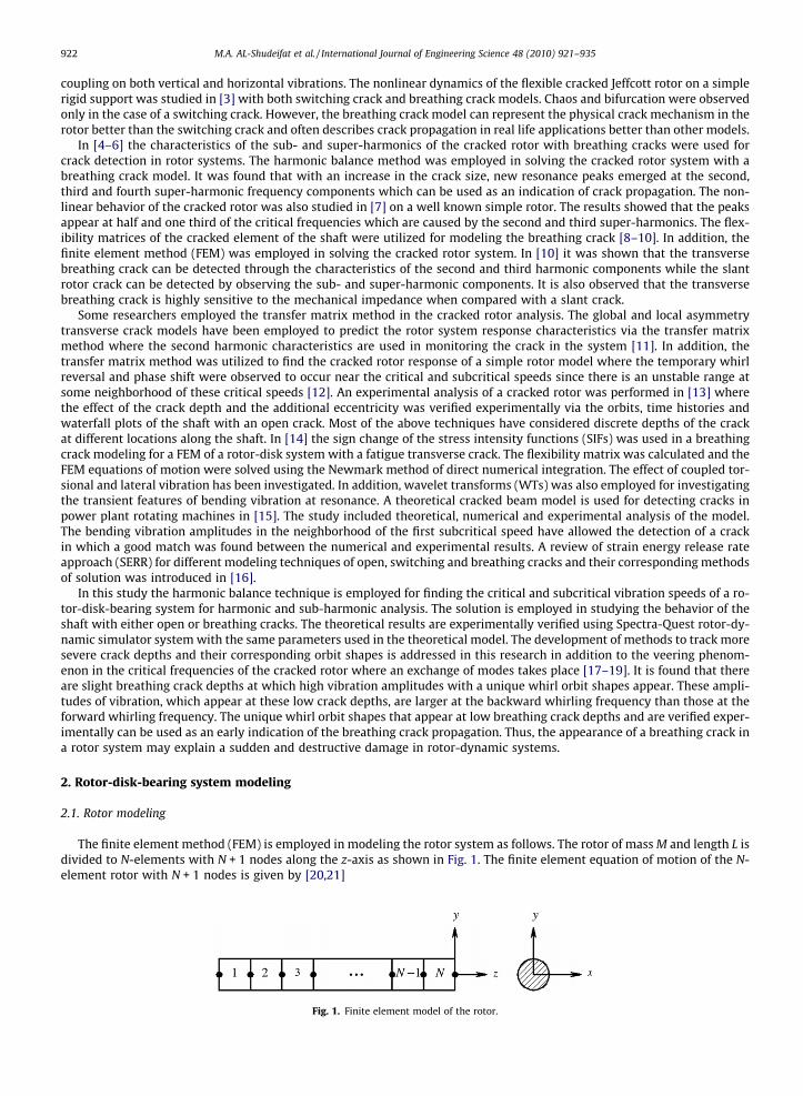
2.1. Rotor modeling
The finite element method (FEM) is employed in modeling the rotor system as follows. The rotor of mass M and length L isdivided to N-elements with N + 1 nodes along the z-axis as shown in Fig. 1. The finite element equation of motion of the N-element rotor with N + 1 nodes is given by [20,21]
Fig. 1. Finite element model of the rotor.
M.A. AL-Shudeifat et al. / International Journal of Engineering Science 48 (2010) 921–935 923
M€qðtÞ þ ðCþ GÞ _qðtÞ þ KqðtÞ ¼ FuðtÞ þ Fg ; ð1Þ
where qðtÞ ¼ qT1 qT
2 . . . qTi . . . qT
Nþ1
� �T is the 4(N + 1) � 1 dimensional nodal displacement vector, qTi ðtÞ ¼ ui mi /x
i /yi
� �is the sin-
gle node displacement vector consisting of the translational and rotational displacements about the stationary X and Y axesfor i = 1, 2, . . ., N + 1, FuðtÞ is the 4(N + 1) � 1 unbalance force vector, and Fg is the 4(N + 1) � 1 gravity force vector. The M, K,C, G are the global mass, stiffness, damping, and gyroscopic matrices, respectively, where each is of dimension4(N + 1) � 4(N + 1).
The jth element has two nodes at i = j and i = j + 1. The single element equation of motion is therefore obtained as
mj€̂qjðtÞ þ ðcj þ gjÞ _̂qjðtÞ þ kjq̂jðtÞ ¼ f̂ujðtÞ þ f̂gj; ð2Þ
where q̂jðtÞ ¼ ui mi /xi /y
i uiþ1 miþ1 /xiþ1 /y
iþ1
� �T; f̂ujðtÞ and f̂gj are the 8 � 1 unbalance force and gravity force vectors at the jth
element nodes, f̂ujðtÞ ¼ FiuðtÞ
� �TFiþ1
u ðtÞ� �T
� �T
where FiuðtÞ and Fiþ1
u ðtÞ are the 4 � 1 unbalance force vectors at nodes i and i + 1,
respectively, mj ¼m1j þm2
j where m1j is the jth element classical mass matrix and m2
j is the jth element matrix of the sec-ondary effect of the rotary inertia, kj is the jth element stiffness matrix, cj is the jth element damping matrix where cj ¼ ckj
and c is the proportional damping coefficient, gj is the jth element gyroscopic matrix. The expressions for mj, kj and gj arefound in references [20,21].
2.2. Disk modeling
The disk is placed at a given node that has four degrees of freedom. Therefore its nodal displacement vector isqT
i ðtÞ ¼ ui mi /xi /y
i
� �which is the same as that of the disk center. If the rotor has rigid disks, the mass center of each rigid
disk is assumed to lie at the node that is shared between two elements as shown in Fig. 2. If there is a disk at node i of mass
mid, thickness hi, outer radius Ri
0, inner radius Riin, dimetral moment of inertia Ii
d ¼ mid=12
� 3 Ri
in
� �2þ 3 Ri
o
� �2þ hi� �2
�and
polar moment of inertia Iip ¼ mi
d=2�
Riin
� �2þ Ri
o
� �2 �
. Hence, the equations of motion of the disk at node i are given by[20,21]
mid 0 0 0
0 mid 0 0
0 0 Iid 0
0 0 0 Iid
266664377775
€ui
€mi
€/xi
€/yi
266664377775þX
0 0 0 00 0 0 00 0 0 Ii
p
0 0 �Iip 0
266664377775
_ui
_mi
_/xi
_/yi
266664377775 ¼
0000
2666437775; ð3Þ
where the first matrix is the classical mass matrix and the second one is the gyroscopic matrix of the disk and X is the shaftrotational speed. Since the disks are assumed to be rigid, the stiffness matrix vanishes.
2.3. Bearing modeling
The bearings can be either journal or ball bearings. The model of a bearing is shown in Fig. 3. The equations of the forces atthe bearings are obtained by neglecting the influence of slopes and the bending moment [20]. Hence, if there is a bearing atnode i, the equations of forces at that node are given by
Fu
Fv
F/x
F/y
2666437775
i
¼
kxx 0 0 00 kyy 0 00 0 0 00 0 0 0
2666437775
ui
mi
/xi
/yi
2666437775þ
cxx 0 0 00 cyy 0 00 0 0 00 0 0 0
2666437775
_ui
_mi
_/xi
_/yi
266664377775: ð4Þ
The first matrix is the stiffness matrix and the second is the viscous damping matrix. These matrices are diagonal andsymmetric.
Fig. 2. The rotor-disk finite element model.
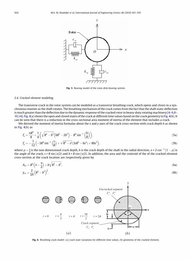
Fig. 3. Bearing model of the rotor-disk-bearing system.
924 M.A. AL-Shudeifat et al. / International Journal of Engineering Science 48 (2010) 921–935
2.4. Cracked element modeling
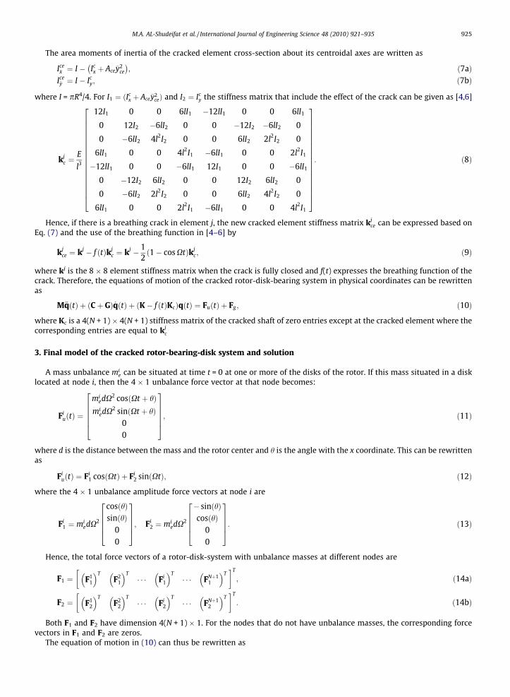
The transverse crack in the rotor system can be modeled as a transverse breathing crack, which opens and closes in a syn-chronous manner as the shaft rotates. The breathing mechanism of the crack comes from the fact that the shaft static deflectionis much greater than the deflection due to the dynamic response of the cracked rotor in heavy-duty rotating machinery [4–6,8–10,14]. Fig. 4(a) shows the open and closed states of the crack at different time values based on the crack geometry in Fig. 4(b). Itcan be seen that there is a reduction in the cross-sectional area moment of inertia of the element that includes a crack.
We derived the moment of inertia formulas about the x and y axes of the crack cross-section with crack depth h as shownin Fig. 4(b) as
Icx ¼
pR4
8þ 1
4
ffiffiffiffiffiffiffiffiffiffiffiffiffiffiffiffiR2 � b2
qbR2 � 2b3� �
� R4 sin�1 bR
� �; ð5aÞ
Icy ¼ �
112�3R4 sin�1 s
R
� �þ
ffiffiffiffiffiffiffiffiffiffiffiffiffiffiffiR2 � s2
pð3sR2 � 6s3Þ þ 8bs3
� �; ð5bÞ
where l ¼ hR is the non-dimensional crack depth, h is the crack depth of the shaft in the radial direction, a = 2 cos�1 (1 � l) is
the angle of the crack, s = R sin (a/2) and b = R cos (a/2). In addition, the area and the centroid of the of the cracked elementcross-section at the crack location are respectively given by
Ace ¼ R2 p� a2
� �þ b
ffiffiffiffiffiffiffiffiffiffiffiffiffiffiffiffiR2 � b2
q; ð6aÞ
�yce ¼2
3AR2 � b2� �3
2: ð6bÞ
0=t2
π=t π=t2
3π=t π2=t
)(a )(b
Uncracked segment ucxI , uc
yI
Crack segment cxI , c
yI
Fig. 4. Breathing crack model: (a) crack state variations for different time values, (b) geometry of the cracked element.
M.A. AL-Shudeifat et al. / International Journal of Engineering Science 48 (2010) 921–935 925
The area moments of inertia of the cracked element cross-section about its centroidal axes are written as
Ice�x ¼ I � Ic
x þ Ace�y2ce
� ; ð7aÞ
Ice�y ¼ I � Ic
y; ð7bÞ
where I = pR4/4. For I1 ¼ ðIcx þ Ace�y2
ceÞ and I2 ¼ Icy the stiffness matrix that include the effect of the crack can be given as [4,6]
kjc ¼
E
l3
12I1 0 0 6lI1 �12lI1 0 0 6lI1
0 12I2 �6lI2 0 0 �12I2 �6lI2 0
0 �6lI2 4l2I2 0 0 6lI2 2l2I2 0
6lI1 0 0 4l2I1 �6lI1 0 0 2l2I1
�12lI1 0 0 �6lI1 12I1 0 0 �6lI1
0 �12I2 6lI2 0 0 12I2 6lI2 0
0 �6lI2 2l2I2 0 0 6lI2 4l2I2 0
6lI1 0 0 2l2I1 �6lI1 0 0 4l2I1
266666666666666664
377777777777777775: ð8Þ
Hence, if there is a breathing crack in element j, the new cracked element stiffness matrix kjce can be expressed based on
Eq. (7) and the use of the breathing function in [4–6] by
kjce ¼ kj � f ðtÞkj
c ¼ kj � 12
1� cos Xtð Þkjc; ð9Þ
where kj is the 8 � 8 element stiffness matrix when the crack is fully closed and f(t) expresses the breathing function of thecrack. Therefore, the equations of motion of the cracked rotor-disk-bearing system in physical coordinates can be rewrittenas
M€qðtÞ þ ðCþ GÞ _qðtÞ þ ðK� f ðtÞKcÞqðtÞ ¼ FuðtÞ þ Fg ; ð10Þ
where Kc is a 4(N + 1) � 4(N + 1) stiffness matrix of the cracked shaft of zero entries except at the cracked element where thecorresponding entries are equal to kj
c
3. Final model of the cracked rotor-bearing-disk system and solution
A mass unbalance mie can be situated at time t = 0 at one or more of the disks of the rotor. If this mass situated in a disk
located at node i, then the 4 � 1 unbalance force vector at that node becomes:
FiuðtÞ ¼
miedX2 cosðXt þ hÞ
miedX2 sinðXt þ hÞ
00
266664377775; ð11Þ
where d is the distance between the mass and the rotor center and h is the angle with the x coordinate. This can be rewrittenas
FiuðtÞ ¼ Fi
1 cosðXtÞ þ Fi2 sinðXtÞ; ð12Þ
where the 4 � 1 unbalance amplitude force vectors at node i are
Fi1 ¼ mi
edX2
cosðhÞsinðhÞ
00
2666437775; Fi
2 ¼ miedX2
� sinðhÞcosðhÞ
00
2666437775: ð13Þ
Hence, the total force vectors of a rotor-disk-system with unbalance masses at different nodes are
F1 ¼ F11
� �TF2
1
� �T� � � Fi
1
� �T� � � FNþ1
1
� �T� �T
; ð14aÞ
F2 ¼ F12
� �TF2
2
� �T� � � Fi
2
� �T� � � FNþ1
2
� �T� �T
: ð14bÞ
Both F1 and F2 have dimension 4(N + 1) � 1. For the nodes that do not have unbalance masses, the corresponding forcevectors in F1 and F2 are zeros.
The equation of motion in (10) can thus be rewritten as
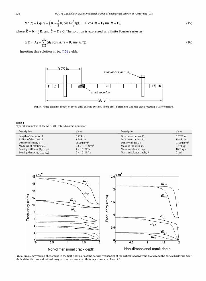
Table 1Physica
Desc
LengRadiDensModBearBear
Fig. 6.(dashed
926 M.A. AL-Shudeifat et al. / International Journal of Engineering Science 48 (2010) 921–935
M€qðtÞ þ bC _qðtÞ þ eK � 12
Kc cos Xt �
qðtÞ ¼ F1 cos Xt þ F2 sin Xt þ Fg ; ð15Þ
where eK ¼ K� 12 Kc and bC ¼ Cþ G. The solution is expressed as a finite Fourier series as
qðtÞ ¼ A0 þXn
k¼1
Ak cos kXtð Þ þ Bk sin kXtð Þð Þ: ð16Þ
Inserting this solution in Eq. (15) yields:
Fig. 5. Finite element model of rotor-disk-bearing system. There are 18 elements and the crack location is at element 6.
l parameters of the MFS–RDS rotor-dynamic simulator.
ription Value Description Value
th of the rotor, L 0.724 m Disk outer radius, Ro 0.0762 mus of the rotor, R 1.588 mm Disk inner radius, Ri 15.88 mmity of rotor, q 7800 kg/m3 Density of disk, q 2700 kg/m3
ulus of elasticity, E 2.1 � 1011 N/m2 Mass of the disk, md 0.571 kging stiffness, (kxx, kyy) 7 � 107 N/m Mass unbalance, med 10�6 kg ming damping, (cxx, cyy) 5 � 102 Ns/m Mass unbalance angle, h 0 rad
Frequency veering phenomena in the first eight pairs of the natural frequencies of the critical forward whirl (solid) and the critical backward whirl) for the cracked rotor-disk-system versus crack depth for open crack in element 6.
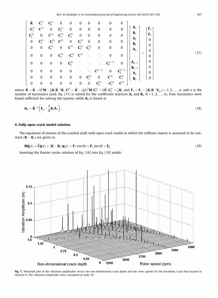
Fig. 7.elemen
M.A. AL-Shudeifat et al. / International Journal of Engineering Science 48 (2010) 921–935 927
bK Cð1Þ1 Cð1Þ2 0 0 0 0 0 0 0
�Cð1Þ1 Cð1Þ 0 Cð1Þ2 0 0 0 0 0 0
Cð2Þ2 0 Cð2Þ Cð2Þ1 Cð2Þ2 0 0 0 0 0
0 Cð2Þ2 �Cð2Þ1 Cð2Þ 0 Cð2Þ2 0 0 0 0
0 0 Cð3Þ2 0 Cð3Þ Cð3Þ1 Cð3Þ2 0 0 0
0 0 0 Cð3Þ2 �Cð3Þ1 Cð3Þ . .. . .
.0 0
0 0 0 0 Cð4Þ2. .
. . .. . .
.Cðn�1Þ
2 0
0 0 0 0 0 . .. . .
.Cðn�1Þ 0 Cðn�1Þ
2
0 0 0 0 0 0 CðnÞ2 0 CðnÞ CðnÞ1
0 0 0 0 0 0 0 CðnÞ2 �CðnÞ1 CðnÞ
2666666666666666666666666664
3777777777777777777777777775
A1
B1
A2
B2
A3
..
.
An�1
Bn�1
An
Bn
26666666666666666666664
37777777777777777777775
¼
eF1
F2
0
0
0
0
0
0
0
0
2666666666666666666664
3777777777777777777775
; ð17Þ
where bK ¼ eK �X2M� 18 Kc
eK�1Kc;CðjÞ ¼ eK � ðjXÞ2M;CðjÞ1 ¼ XbC;CðjÞ2 ¼ 1
4 Kc and eF1 ¼ F1 � 12 Kc
eK�1Fg ; j ¼ 1;2; . . . ;n, and n is thenumber of harmonics used. Eq. (17) is solved for the coefficient matrices Ak and Bk (k = 1, 2, . . ., n). Four harmonics werefound sufficient for solving the system, while A0 is found as
A0 ¼ eK�1 Fg �14
KcA1
�: ð18Þ
4. Fully open crack model solution
The equations of motion of the cracked shaft with open crack model in which the stiffness matrix is assumed to be con-stant (K � Kc) are given as
M€qðtÞ þ bC _qðtÞ þ ðK� KcÞqðtÞ ¼ F1 cos Xt þ F2 sin Xt þ Fg : ð19Þ
Inserting the Fourier series solution of Eq. (16) into Eq. (19) yields:
Waterfall plot of the vibration amplitudes versus the non-dimensional crack depth and the rotor speeds for the breathing crack that located int 6. The vibration amplitudes were calculated at node 10.
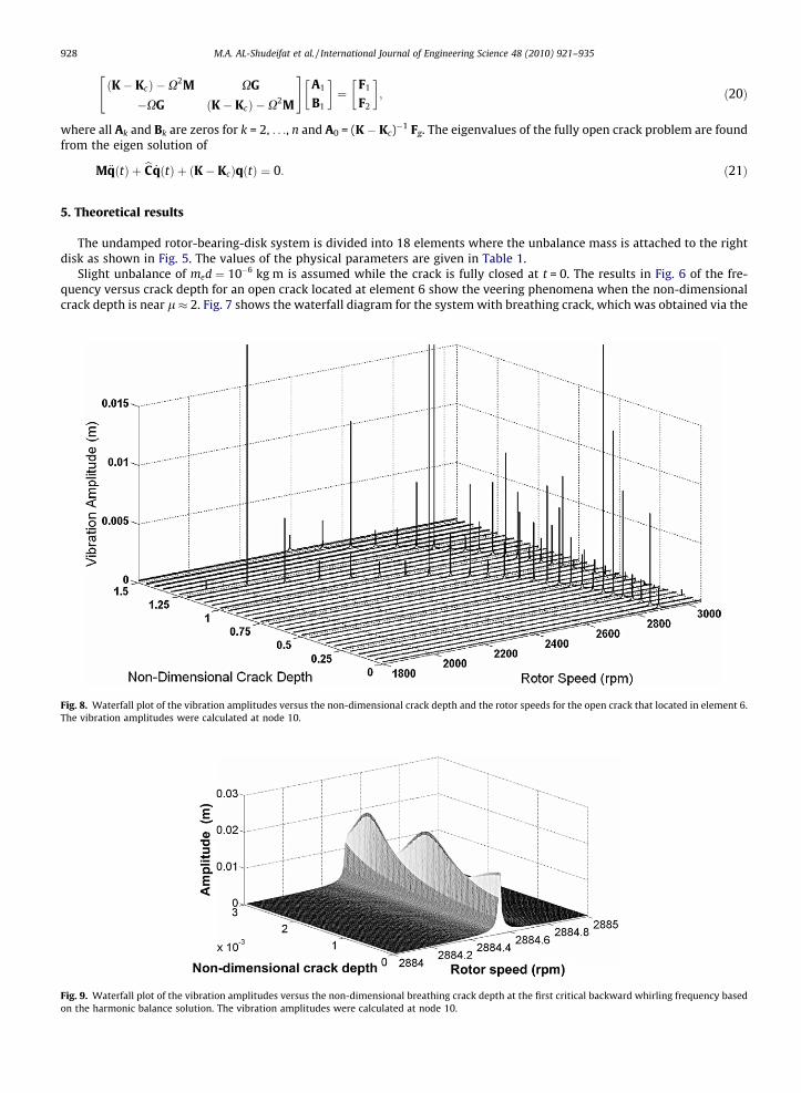
Fig. 9.on the
Fig. 8.The vib
928 M.A. AL-Shudeifat et al. / International Journal of Engineering Science 48 (2010) 921–935
ðK� KcÞ �X2M XG
�XG ðK� KcÞ �X2M
" #A1
B1
� �¼
F1
F2
� �; ð20Þ
where all Ak and Bk are zeros for k = 2, . . ., n and A0 = (K � Kc)�1 Fg. The eigenvalues of the fully open crack problem are foundfrom the eigen solution of
M€qðtÞ þ bC _qðtÞ þ ðK� KcÞqðtÞ ¼ 0: ð21Þ
5. Theoretical results
The undamped rotor-bearing-disk system is divided into 18 elements where the unbalance mass is attached to the rightdisk as shown in Fig. 5. The values of the physical parameters are given in Table 1.
Slight unbalance of med ¼ 10�6 kg m is assumed while the crack is fully closed at t = 0. The results in Fig. 6 of the fre-quency versus crack depth for an open crack located at element 6 show the veering phenomena when the non-dimensionalcrack depth is near l � 2. Fig. 7 shows the waterfall diagram for the system with breathing crack, which was obtained via the
Waterfall plot of the vibration amplitudes versus the non-dimensional breathing crack depth at the first critical backward whirling frequency basedharmonic balance solution. The vibration amplitudes were calculated at node 10.
Waterfall plot of the vibration amplitudes versus the non-dimensional crack depth and the rotor speeds for the open crack that located in element 6.ration amplitudes were calculated at node 10.
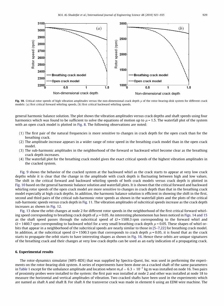
Fig. 10. Critical rotor speeds of high vibration amplitudes versus the non-dimensional crack depth l of the rotor-bearing-disk system for different crackmodels: (a) first critical forward whirling speeds, (b) first critical backward whirling speeds.
M.A. AL-Shudeifat et al. / International Journal of Engineering Science 48 (2010) 921–935 929
general harmonic balance solution. The plot shows the vibration amplitudes versus crack depths and shaft speeds using fourharmonics which was found to be sufficient to solve the equations of motion up to l = 1.5. The waterfall plot of the systemwith an open crack model is plotted in Fig. 8. The following observations are noted:
(1) The first pair of the natural frequencies is more sensitive to changes in crack depth for the open crack than for thebreathing crack.
(2) The amplitude increase appears in a wider range of rotor speed in the breathing crack model than in the open crackmodel.
(3) The sub-harmonic amplitudes in the neighborhood of the forward or backward whirl become clear as the breathingcrack depth increases.
(4) The waterfall plot for the breathing crack model gives the exact critical speeds of the highest vibration amplitudes inthe cracked system.
Fig. 9 shows the behavior of the cracked system at the backward whirl as the crack starts to appear at very low crackdepths while it is clear that the change in the amplitude with crack depth is fluctuating between high and low values.The shift in the critical forward and backward whirling speeds of both crack models versus crack depth is plotted inFig. 10 based on the general harmonic balance solution and waterfall plots. It is shown that the critical forward and backwardwhirling rotor speeds of the open crack model are more sensitive to changes in crack depth than that in the breathing crackmodel especially at high crack depths. In addition, the harmonic balance solution is efficient in showing the shift in the first,second and third pairs of the critical sub-harmonic rotor speeds as shown in the waterfall plots and the plots of the criticalsub-harmonic speeds versus crack depth in Fig. 11. The vibration amplitudes of subcritical speeds increase as the crack depthincreases as shown in Fig. 12.
Fig. 13 show the orbit changes at node 2 for different rotor speeds in the neighborhood of the first critical forward whirl-ing speed corresponding to breathing crack depth of l = 0.05. An interesting phenomenon has been noticed in Figs. 14 and 15as the shaft speed passes through the subcritical speed of X = 1500.3 rpm corresponding to the forward whirl andX = 1460.7 rpm corresponding to backward whirl for a very small breathing crack depth l = 0.05. These shapes of whirl or-bits that appear in a neighborhood of the subcritical speeds are nearly similar to those in [5–7,22] for breathing crack model.In addition, at the subcritical speed X = 1500.3 rpm that corresponds to crack depth l = 0.05, it is found that as the crackstarts to propagate the orbit starts to have interesting shapes as shown in Fig. 16. Hence these orbits are unique signaturesof the breathing crack and their changes at very low crack depths can be used as an early indication of a propagating crack.
6. Experimental results
The rotor-dynamics simulator (MFS–RDS) that was supplied by Spectra-Quest, Inc. was used in performing the experi-ments on the rotor-bearing-disk system. A series of experiments have been done on a cracked shaft of the same parametersin Table 1 except for the unbalance amplitude and location where med ¼ 6:3� 10�5 kg m was installed on node 16. Two pairsof proximity probes were installed to the system: the first pair was installed at node 2 and other was installed at node 18 tomeasure the horizontal and vertical amplitudes of vibration. Two cracked shafts have been used in the experiments whichare named as shaft A and shaft B. For shaft A the transverse crack was made in element 6 using an EDM wire machine. The
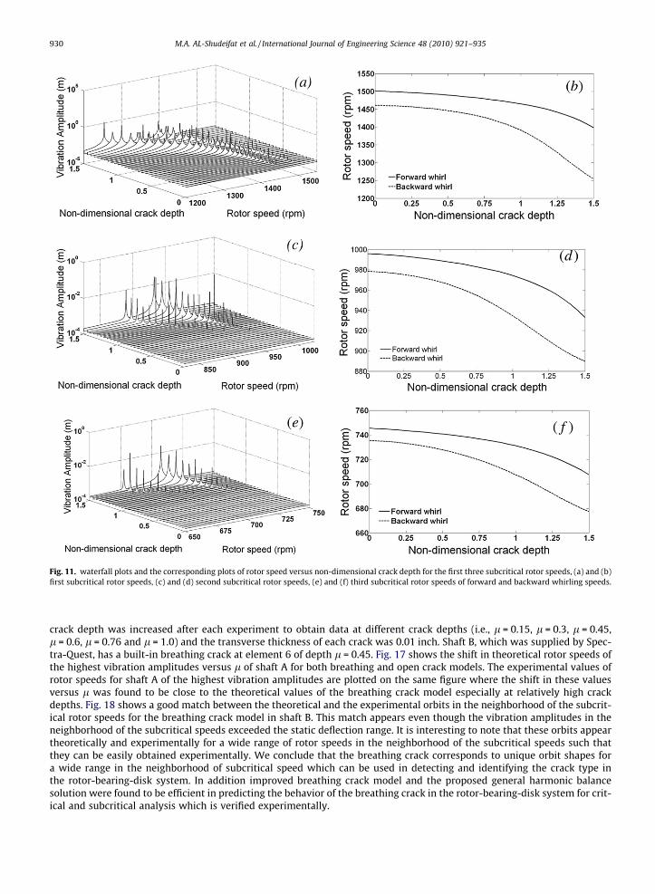
Fig. 11. waterfall plots and the corresponding plots of rotor speed versus non-dimensional crack depth for the first three subcritical rotor speeds, (a) and (b)first subcritical rotor speeds, (c) and (d) second subcritical rotor speeds, (e) and (f) third subcritical rotor speeds of forward and backward whirling speeds.
930 M.A. AL-Shudeifat et al. / International Journal of Engineering Science 48 (2010) 921–935
crack depth was increased after each experiment to obtain data at different crack depths (i.e., l = 0.15, l = 0.3, l = 0.45,l = 0.6, l = 0.76 and l = 1.0) and the transverse thickness of each crack was 0.01 inch. Shaft B, which was supplied by Spec-tra-Quest, has a built-in breathing crack at element 6 of depth l = 0.45. Fig. 17 shows the shift in theoretical rotor speeds ofthe highest vibration amplitudes versus l of shaft A for both breathing and open crack models. The experimental values ofrotor speeds for shaft A of the highest vibration amplitudes are plotted on the same figure where the shift in these valuesversus l was found to be close to the theoretical values of the breathing crack model especially at relatively high crackdepths. Fig. 18 shows a good match between the theoretical and the experimental orbits in the neighborhood of the subcrit-ical rotor speeds for the breathing crack model in shaft B. This match appears even though the vibration amplitudes in theneighborhood of the subcritical speeds exceeded the static deflection range. It is interesting to note that these orbits appeartheoretically and experimentally for a wide range of rotor speeds in the neighborhood of the subcritical speeds such thatthey can be easily obtained experimentally. We conclude that the breathing crack corresponds to unique orbit shapes fora wide range in the neighborhood of subcritical speed which can be used in detecting and identifying the crack type inthe rotor-bearing-disk system. In addition improved breathing crack model and the proposed general harmonic balancesolution were found to be efficient in predicting the behavior of the breathing crack in the rotor-bearing-disk system for crit-ical and subcritical analysis which is verified experimentally.
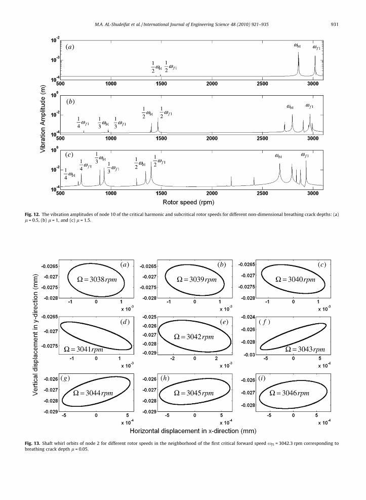
Fig. 12. The vibration amplitudes of node 10 of the critical harmonic and subcritical rotor speeds for different non-dimensional breathing crack depths: (a)l = 0.5, (b) l = 1, and (c) l = 1.5.
Fig. 13. Shaft whirl orbits of node 2 for different rotor speeds in the neighborhood of the first critical forward speed xf1 = 3042.3 rpm corresponding tobreathing crack depth l = 0.05.
M.A. AL-Shudeifat et al. / International Journal of Engineering Science 48 (2010) 921–935 931
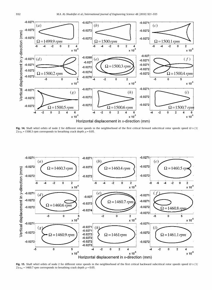
Fig. 14. Shaft whirl orbits of node 2 for different rotor speeds in the neighborhood of the first critical forward subcritical rotor speeds speed X ffi (1/2)xf1 = 1500.3 rpm corresponds to breathing crack depth l = 0.05.
Fig. 15. Shaft whirl orbits of node 2 for different rotor speeds in the neighborhood of the first critical backward subcritical rotor speeds speed X ffi (1/2)xb1 = 1460.7 rpm corresponds to breathing crack depth l = 0.05.
932 M.A. AL-Shudeifat et al. / International Journal of Engineering Science 48 (2010) 921–935
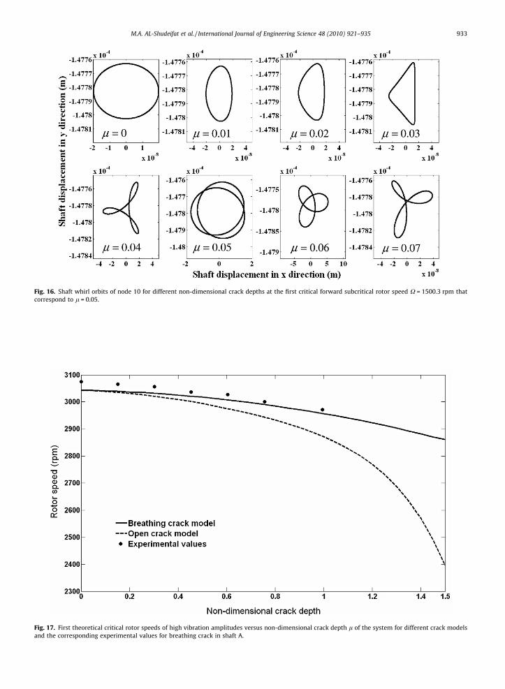
Fig. 16. Shaft whirl orbits of node 10 for different non-dimensional crack depths at the first critical forward subcritical rotor speed X = 1500.3 rpm thatcorrespond to l = 0.05.
Fig. 17. First theoretical critical rotor speeds of high vibration amplitudes versus non-dimensional crack depth l of the system for different crack modelsand the corresponding experimental values for breathing crack in shaft A.
M.A. AL-Shudeifat et al. / International Journal of Engineering Science 48 (2010) 921–935 933
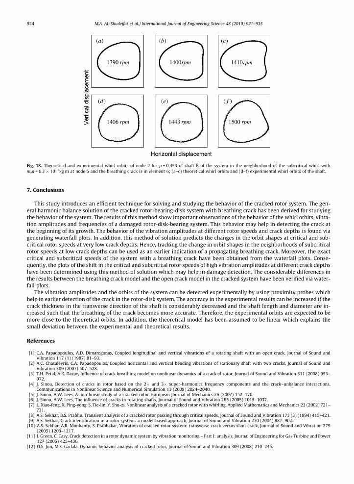
Fig. 18. Theoretical and experimental whirl orbits of node 2 for l = 0.453 of shaft B of the system in the neighborhood of the subcritical whirl withmed = 6.3 � 10�5kg m at node 5 and the breathing crack is in element 6; (a–c) theoretical whirl orbits and (d–f) experimental whirl orbits of the shaft.
934 M.A. AL-Shudeifat et al. / International Journal of Engineering Science 48 (2010) 921–935
7. Conclusions
This study introduces an efficient technique for solving and studying the behavior of the cracked rotor system. The gen-eral harmonic balance solution of the cracked rotor-bearing-disk system with breathing crack has been derived for studyingthe behavior of the system. The results of this method show important observations of the behavior of the whirl orbits, vibra-tion amplitudes and frequencies of a damaged rotor-disk-bearing system. This behavior may help in detecting the crack atthe beginning of its growth. The behavior of the vibration amplitudes at different rotor speeds and crack depths is found viagenerating waterfall plots. In addition, this method of solution predicts the changes in the orbit shapes at critical and sub-critical rotor speeds at very low crack depths. Hence, tracking the change in orbit shapes in the neighborhoods of subcriticalrotor speeds at low crack depths can be used as an earlier indication of a propagating breathing crack. Moreover, the exactcritical and subcritical speeds of the system with a breathing crack have been obtained from the waterfall plots. Conse-quently, the plots of the shift in the critical and subcritical rotor speeds of high vibration amplitudes at different crack depthshave been determined using this method of solution which may help in damage detection. The considerable differences inthe results between the breathing crack model and the open crack model in the cracked system have been verified via water-fall plots.
The vibration amplitudes and the orbits of the system can be detected experimentally by using proximity probes whichhelp in earlier detection of the crack in the rotor-disk system. The accuracy in the experimental results can be increased if thecrack thickness in the transverse direction of the shaft is considerably decreased and the shaft length and diameter are in-creased such that the breathing of the crack becomes more accurate. Therefore, the experimental orbits are expected to bemore close to the theoretical orbits. In addition, the theoretical model has been assumed to be linear which explains thesmall deviation between the experimental and theoretical results.
References
[1] C.A. Papadopoulos, A.D. Dimarogonas, Coupled longitudinal and vertical vibrations of a rotating shaft with an open crack, Journal of Sound andVibration 117 (1) (1987) 81–93.
[2] A.C. Chasalevris, C.A. Papadopoulos, Coupled horizontal and vertical bending vibrations of stationary shaft with two cracks, Journal of Sound andVibration 309 (2007) 507–528.
[3] T.H. Petal, A.K. Darpe, Influence of crack breathing model on nonlinear dynamics of a cracked rotor, Journal of Sound and Vibration 311 (2008) 953–972.
[4] J. Sinou, Detection of cracks in rotor based on the 2� and 3� super-harmonics frequency components and the crack–unbalance interactions,Communications in Nonlinear Science and Numerical Simulation 13 (2008) 2024–2040.
[5] J. Sinou, A.W. Lees, A non-linear study of a cracked rotor, European Journal of Mechanics 26 (2007) 152–170.[6] J. Sinou, A.W. Lees, The influence of cracks in rotating shafts, Journal of Sound and Vibration 285 (2005) 1015–1037.[7] L. Xiao-feng, X. Ping-yong, S. Tie-lin, Y. Shu-zi, Nonlinear analysis of a cracked rotor with whirling, Applied Mathematics and Mechanics 23 (2002) 721–
731.[8] A.S. Sekhar, B.S. Prabhu, Transient analysis of a cracked rotor passing through critical speeds, Journal of Sound and Vibration 173 (3) (1994) 415–421.[9] A.S. Sekhar, Crack identification in a rotor system: a model-based approach, Journal of Sound and Vibration 270 (2004) 887–902.
[10] A.S. Sekhar, A.R. Monhanty, S. Prabhakar, Vibration of cracked rotor system: transverse crack versus slant crack, Journal of Sound and Vibration 279(2005) 1203–1217.
[11] I. Green, C. Casy, Crack detection in a rotor dynamic system by vibration monitoring – Part I: analysis, Journal of Engineering for Gas Turbine and Power127 (2005) 425–436.
[12] O.S. Jun, M.S. Gadala, Dynamic behavior analysis of cracked rotor, Journal of Sound and Vibration 309 (2008) 210–245.
M.A. AL-Shudeifat et al. / International Journal of Engineering Science 48 (2010) 921–935 935
[13] T. Zhou, Z. Sun, J. Xu, W. Han, Experimental analysis of a cracked rotor, Journal of Dynamic Systems, Measurements, and Control 127 (2005) 313–320.[14] A.K. Darpe, A novel way to detect transverse surface crack in a rotating shaft, Journal of Sound and Vibration 305 (2007) 151–171.[15] C.A. Papadopoulos, The strain energy release approach for modeling cracks in rotors: a state of the art review, Mechanical Systems and Signal
Processing 22 (2008) 763–789.[16] C.M. Stoisser, S. Audebert, A comprehensive theoretical, numerical and experimental approach for crack detection in power plant rotating machinery,
Mechanical Systems and Signal Processing 22 (2008) 818–844.[17] N.C. Perkins, C.D. Mote, Comments on curve veering in eigenvalue problems, Journal of Sound and Vibration 106 (3) (1986) 451–463.[18] C. Pierre, Mode localization and eigenvalue loci veering phenomena in disordered structure, Journal of Sound and Vibration 126 (3) (1988) 485–502.[19] P.T. Chen, J.H. Ginsberg, On the relationship between veering of eigenvalue loci and parameter sensitivity of eigenfunctions, Journal of Vibration and
Acoustics 114 (1992) 141–148.[20] M. Lalanne, G. Ferraris, Rotor Dynamics Prediction in Engineering, second ed., John Willy and Sons, New York, 1998.[21] T. Yamamoto, Y. Ishida, Linear and Nonlinear Rotordynamics, second ed., John Willy and Sons, New York, 2001.[22] A.K. Darpe, K. Gupta, A. Chawla, Transient response and breathing behavior of a cracked Jeffcott rotor, Journal of Sound and Vibration 272 (2004) 207–
243.


![Welcome! [mc2.nmsu.edu] · FAQs generated during the live presentation. Please submit any questions or comments to mc2@nmsu.edu. Addition & Subtraction within 100 Extending …](https://img.pdfslide.net/doc/110x75/5f66521c578fe244b513589f/welcome-mc2nmsuedu-faqs-generated-during-the-live-presentation-please-submit.jpg)