Embed Size (px)
Citation preview
International Journal of Heat and Mass Transfer 66 (2013) 271–278
Contents lists available at ScienceDirect
International Journal of Heat and Mass Transfer
journal homepage: www.elsevier .com/locate / i jhmt
Thermal analysis and design of a multi-layered rigidity tunablecomposite
0017-9310/$ - see front matter � 2013 Elsevier Ltd. All rights reserved.http://dx.doi.org/10.1016/j.ijheatmasstransfer.2013.07.031
⇑ Corresponding author. Tel.: +1 732 208 8800.E-mail addresses: [email protected], [email protected] (W.L. Shan).
W.L. Shan a,⇑, T. Lu a, Z.H. Wang b, C. Majidi a
a Soft Machines Lab, Department of Mechanical Engineering, Carnegie Mellon University, Pittsburgh, PA 15213, USAb School of Sustainable Engineering and the Built Environment, Arizona State University, Tempe, AZ 85287, USA
a r t i c l e i n f o
Article history:Received 18 April 2013Received in revised form 8 July 2013Accepted 9 July 2013
Keywords:Rigidity tunable compositeJoule heatingPhase changeLow melting-point alloyShape memory polymerLatent heat accumulation
a b s t r a c t
Elastomer-based composites embedded with thermally-responsive material (TRM) and a liquid-phaseJoule heater are capable of reversibly changing their elastic rigidity by up to four orders of magnitude.At room temperature, the TRM layer is rigid and prevents the surrounding elastomer from elasticallybending or stretching. When activated, the embedded Joule heater softens or melts the TRM, which leadsto a dramatic reduction in the elastic rigidity of the composite. In this manuscript, we examine the acti-vation of these composites by performing analytical, numerical, and experimental studies of the temper-ature distribution, thermal history, and phase transition. We consider both low melting point (LMP)metal alloys (e.g. Field’s metal) and shape memory polymer (SMP). An analytical solution using the Galer-kin Based Integral (GBI) method is derived for the cases where no phase change is involved, while anumerical scheme using the Latent Heat Accumulation (LHA) method is utilized to probe scenarios wherephase change has a central role in the elastic rigidity change. The analytical and numerical studies predicta temperature history that is in good agreement with experimental measurements obtained with an IRthermometer. Analysis of the internal temperature distribution leads to scaling laws for determiningthe required activation time and allowable input power rate for composites containing either LMP alloysor SMP. These scaling laws could potentially be used to inform the design of rigidity tunable composites(RTC) used in assistive wearable technologies and biologically-inspired soft-matter robotics.
� 2013 Elsevier Ltd. All rights reserved.
1. Introduction
Inspired by natural muscle and the catch connective tissue inechinoderms such as sea cucumbers [1], rigidity tunable materialsrepresent an exciting new area in the emerging field of biologi-cally-inspired robotics. These rigidity tunable materials have po-tential applications in both the military for injury prevention andcivilian realms such as wearable robotic assistive devices [2]. Pre-vious efforts for rigidity tunable multifunctional materials includeusing chemically tuned nano-composite [1], magneto-rheologicalfluids [3,4], and pneumatic particle jamming [5,6]. While promis-ing for rigidity control in conventional machines and robotics,these methods require external pneumatic, fluidic, and mechanicalhardware that may limit their functionality in soft or miniaturizedhost platforms.
In recent years, engineers have demonstrated reversible elasticrigidity tuning with shape memory polymer-steel laminate com-posites that are activated with external heating [7,8]. The shapememory polymer exhibits variable stiffness and functions as a con-nective medium that controls the relative displacement of the rigid
components. At lower temperature the laminate has high flexuralrigidity. Upon external heating, however, the SMP softens and al-lows for translation of the rigid components during deformation.The resulting change in rigidity can be as large as two orders ofmagnitude. This approach still requires external heating, but thelaminate hybrid composite concept opens up new opportunitiesfor design of multifunctional materials with tunable rigidity.
Based on previous efforts, including the recent development ofmasked deposition techniques for elastically soft electronics [9,10],most recently Shan et al. have fabricated rigidity tunable compos-ites (RTC) with an on-board soft heater [2]. These composites arecomposed of multiple layers of acrylic VHB tape with low meltingpoint (LPM) metal alloys, such as Field’s metal, or with shape mem-ory polymer (SMP). This prototype demonstrates rigidity changesof up to four orders of magnitude [2]. The integrated soft heatercomponent allows the RTC to be used in applications such as wear-able assistive devices that require on-board functionality and lowpower input.
Although promising, the actuation mechanism and underlyingphysics for RTC technologies with embedded soft-matter heatershas yet to be adequately examined. The presence of phase changeand heterogeneity between composite layers presents modelingchallenges. There have been recent efforts on analytical and
Nomenclature
A,B,D,P matricesa thermal diffusivity [m2/s]b,d,L dimensions of samples [m]Cp specific heat [J/kg/K]~dn eigenvectorsfi(x) basis functiong(x,t) heat source intensity [J/m3/s]h heat transfer coefficient [W/m2/K]I current [A]P power [W]q heat flow rate [W]R electrical resistance [X]T(x,t) temperature [�C]
Greeks‘ specific latent heat [J/kg]q density [kg/m3]j thermal conductivity [W/m/K]cn eigenvaluesdi,bi,gi coeffcientsh(x,t) differential temperature [�C]
AbbreviationsTRM thermally-responsive materialsGBI Galerkin Based IntegralHBI heat balance integralSMP shape memory polymerLHA latent heat accumulationRTC rigidity tunable compositeLMP low melting-point
SubscriptsG GalinstanV VHBF Field’s metalS SMPair air related variablesg glass transition temperaturemelt melting pointef effective valuee inclusions, Galinstan, or Field’s metal, or SMP
272 W.L. Shan et al. / International Journal of Heat and Mass Transfer 66 (2013) 271–278
numerical modeling of phase change in 1-D infinite domains [11–15]. There have also been heat diffusion modeling in compositescontaining heterogeneous materials [16–21]. The combination ofthese efforts may provide solutions for modeling the current RTCcomposite design.
Typical analytical approaches to solve a heat diffusion equationinclude separation of variables, Green’s function method, the HeatBalance Integral (HBI) method, and the Galerkin Based Integral(GBI) method [20,22-24]. Here, because of the relatively complexgeometry and heterogenous materials properties, an exactclosed-form analytical solution is not readily available. Thus weturn to the integral methods for an approximated solution that isclosed-form [22].
The HBI method was first used by von Karman and Pohlhausento solve boundary-layer problem in fluid mechanics [25]. Goodmanthen introduced its use in a one dimensional melting problem [26].Since then this method has found many applications in the solu-tion of one-dimensional heat transfer problems including theone-phase Stefan problem and linear hyperbolic heat-conductionsproblems on a semi-infinite medium [12-15]. However, these stud-ies cannot be easily extended to a multi-layered problem involvingheat generation and phase change within finite domains. TheGalerkin based integral method used by Haji-Sheikh et al., whichsuccessfully handles heterogeneous material properties [16–18],is more naturally suitable for the problem at hand.
The most popular numerical approaches to one dimensionalheat diffusion problems involving phase changes are the enthalpymethods [27–29,11], including many variants such as the apparentheat capacity method [29], and the latent heat accumulation (LHA)method [11]. These methods typically avoid the explicit tracking ofthe phase change front and thus are easier to implement and re-quire less computational cost. The apparent heat capacity methodintroduces an enormously large heat capacity over a very small re-gion around the phase change temperature to account for the la-tent heat absorbed during phase change [11]. The LHA methodbased on finite volume formulation, however, not only providesthe flexibility to track the melting front but also ensures the con-servation of energy over the whole domain [11].
In this manuscript, we perform a comprehensive study toexamine the activation of RTCs embedded with liquid metal al-
loys and elastomers. The purpose of this paper is to identifythe scaling laws that govern the activation times and powerrequirements for this new class of rigidity-tunable composite.First, an analytical model based on the GBI approach is estab-lished and used for rigidity tuning without phase change. Nexta one dimensional finite volume numerical model is developedbased on the LHA approach to simulate cases involving a con-stant-temperature melting process. The predicted surface tem-perature of the composite is then compared with experimentalmeasurements and provides feedback to the numerics. After con-firming the validity of the models, temperature profile withinthe composite are predicted and guidelines on material choicefor the RTC are discussed.
2. Material and methods
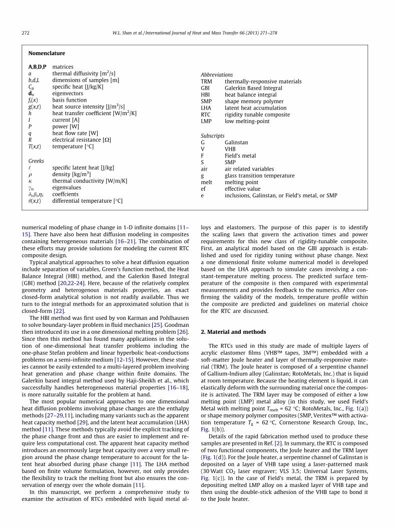
The RTCs used in this study are made of multiple layers ofacrylic elastomer films (VHB™ tapes, 3M™) embedded with asoft-matter Joule heater and layer of thermally-responsive mate-rial (TRM). The Joule heater is composed of a serpentine channelof Gallium-Indium alloy (Galinstan; RotoMetals, Inc.) that is liquidat room temperature. Because the heating element is liquid, it canelastically deform with the surrounding material once the compos-ite is activated. The TRM layer may be composed of either a lowmelting point (LMP) metal alloy (in this study, we used Field’sMetal with melting point Tmelt = 62 �C; RotoMetals, Inc., Fig. 1(a))or shape memory polymer composites (SMP, Veritex™ with activa-tion temperature Tg = 62 �C, Cornerstone Research Group, Inc.,Fig. 1(b)).
Details of the rapid fabrication method used to produce thesesamples are presented in Ref. [2]. In summary, the RTC is composedof two functional components, the Joule heater and the TRM layer(Fig. 1(d)). For the Joule heater, a serpentine channel of Galinstan isdeposited on a layer of VHB tape using a laser-patterned mask(30 Watt CO2 laser engraver; VLS 3.5; Universal Laser Systems,Fig. 1(c)). In the case of Field’s metal, the TRM is prepared bydepositing melted LMP alloy on a masked layer of VHB tape andthen using the double-stick adhesion of the VHB tape to bond itto the Joule heater.
(c)
(b)
(d)
(a)
5mm
VHB
VHB
VHB
Side View
4.5mm
Fig. 1. Rigidity Tunable Composites using (a) Field’s metal and (b) shape memorypolymer. (c) zoomed-in view of serpentine Galinstan channels of soft heater (d) sideview of the RTC sample.
W.L. Shan et al. / International Journal of Heat and Mass Transfer 66 (2013) 271–278 273
At room temperature, the embedded Field’s metal solidifies intoa solid strip that prevents the surrounding VHB tape from elasti-cally stretching or bending. When the Joule heater is activated,the Field’s metal melts and the elastic rigidity of the composite isgoverned by the VHB tape, which has an elastic modulus ofapproximately 128 kPa [2]. This leads to a dramatic reduction inthe nominal elastic rigidity of the composite, which is defined asthe force required to stretch the composite by a small amount ofstrain (� < 1%) divided by the product of strain and the cross-sec-tional area of the composite.
Referring Fig. 1b, we have also produced RTC samples with SMP.This replacement effectively reduces the rigidity change achievabledue to a narrower rigidity change of the SMP itself. However, usingSMP eliminates the need to deposit Field’s metal at elevated tem-peratures, further simplifying the fabrication process.
In this study, VHB tapes with two thicknesses, 0.5 mm and1.0 mm are used. The Galinstan channel is engraved within ab = 0.5 mm VHB layer and the channels are 1.27 mm wide and1.23 mm apart (Fig. 1(c)). The Field’s metal or SMP layer of thick-ness 1.0 mm is embedded within a laser engraved 1.0 mm VHBtape layer. The total thickness of the RTC sample is 9b = 4.5 mm(Fig. 1(d)), while the width d = 15 mm and the length L = 42 mm.
2.1. Analytical heat transfer modeling
We examine the thermal activation of the RTC with an analysisthat models how the heat generated by the Joule heating elementsdiffuses through the thickness of the composite. This is accom-plished with a transient heat transfer analysis on a simplifiedone-dimensional representation of the multi-layered composite
Fig. 2. Schematics of the RTC samples, 1-D simplification through the thickness.
(Fig. 2). By adopting a 1-D model, we assume that the heat lossfrom the edges of the composite are negligible compared to theheat loss from the top and bottom surfaces.
The governing equation for heat transfer in each layer withinthe composite is:
jðxÞ @2T@x2 þ gðx; tÞ ¼ qðxÞCpðxÞ
@T@t; ðx 2 ½0;9b�Þ ð1Þ
where T = T(x,t) is the temperature at position x at time t; q(x) = qi,-i 2 {V, G, F, S} is the density of the corresponding material, that is,VHB, Galinstan, Field’s metal or SMP; similarly, Cp(x) is the specificheat, j(x) is the thermal conductivity, and g(x,t) is the heat sourceterm. Note that we have assumed that the material properties donot change with temperature and time, while they are piecewisecontinuous in space.
The temperature and the heat flux across the interfaces withinthe composite are continuous, despite the piecewise continuousmaterial properties. These post additional restraints on the thermalfield:
qinter� ¼ qinterþ ;
T inter� ¼ T interþ :ð2Þ
The heat source term g(x,t) is a nonzero constant in the Galin-stan layer as we input constant Joule heating power, which heatsup the composite overall. In all other layers, i.e., whenx 2 [0,2b] [ [3b,9b], the heat source term g(x,t) = 0. On the bound-aries, the heat loss rate will be determined by free air convectionbetween the composite surfaces and the surroundingenvironment:
qjx¼0 ¼ hairðTjx¼0 � TairÞ;qjx¼9b ¼ hairðTjx¼9b � TairÞ;
ð3Þ
where q ¼ k @T@x jx¼0;L � ~n is the heat flux out of the top or bottom sur-
face of the RTC sample and ~n is the surface normal, hair is the free airconvection heat transfer coefficient for elastomer surface, and Tair isthe ambient air temperature. In addition, the initial temperature ofthe sample is at environmental temperature:
Tðx;0Þ ¼ Tair: ð4Þ
If we define a new variable h(x,t) = T(x,t) � Tair and assume thatthe environmental temperature Tair is constant, then the governingequation for h is identical to Eq. (1) while the convective boundaryconditions in Eq. (3) and initial temperature in Eq. (4) are all trans-formed to homogeneous ones:
jðxÞ @2h@x2 þ gðx; tÞ ¼ qðxÞCpðxÞ
@h@t; ðx 2 ½0; L�Þ
hinter� ¼ hinterþ ;
kinter�@h@xjinter� ¼ kinterþ
@h@xjinterþ ;
@h@x� hairh
� �jx¼0 ¼ 0;
� @h@x� hairh
� �jx¼L ¼ 0;
hðx;0Þ ¼ 0:
ð5Þ
Using the principle of variation of parameters, the solution to theinhomogeneous governing diffusion equation with homogeneousconvective boundary conditions and homogeneous initial conditionEq. (5) can be written in the following form:
hðx; tÞ ¼XN
n¼1
cnðtÞFnðxÞ expð�cntÞ; ð6Þ
274 W.L. Shan et al. / International Journal of Heat and Mass Transfer 66 (2013) 271–278
where
FnðxÞ ¼XN
i¼1
dnifiðxÞ ð7Þ
and ~dn ¼ ðdn1; dn2; � � � ;dnNÞ is the eigenvector corresponding toeigenvalue cn with fi(x) the basis functions. The values of cn and~dn can be derived from:
ðAþ cnBÞ � ~dn ¼ 0; ð8Þ
in which A and B are N � N matrices with elements in the followingform:
aij ¼Z L
0fir � ðkrfjÞdx; ð9Þ
bij ¼Z L
0qCpfifjdx: ð10Þ
The coefficients cn can be obtained in the following manner[22]:
cnðtÞ ¼XN
i¼1
pni
Z t
0g�i ðsÞ expðcnsÞds; ð11Þ
where pni are the elements of N � N matrix P = [(DB)T]�1 and g�i ðtÞ isdefined as follows:
g�i ðtÞ ¼Z L
0gðx; tÞfiðxÞdx; ð12Þ
where D is a N � N matrix with ~dn as its row vectors.The next step is to find a set of basis functions fi(x). These are
linearly independent polynomial functions that are chosen in away that they satisfy all of the homogenous boundary conditions.The multi-layered composite can be interpreted as a homogeneousblock of VHB elastomer with two inclusions, Galinstan and Field’smetal/SMP, with negligible contact resistance between the layers.In this way, we can obtain the basis functions fi(x) as polynomials[22]:
fiðxÞ ¼ ðdix2 þ bixþ giÞxi�1; ð13Þ
where di,bi and gi are constant coefficients readily available on pp.319 of Ref. [22].
To accommodate the presence of heterogeneous inclusion,these basis functions need to be modified to be piecewise continu-ous at the interfaces to allow for continuous temperature and heatflux conditions, as in Eq. (5). Given the layered geometry in thecomposite, there are two interfaces between each inclusion andthe surrounding VHBs. Thus additional polynomials of cubic powerare assumed for fie:
fie ¼ fi þ ri1x3 þ ri2x2 þ ri3xþ ri4: ð14Þ
Since there are two inclusions, there are eight coefficients rjk
corresponding to each basis function. Once the piecewise continu-ous basis functions are available, the matrices A,B,D,P and cn are alldetermined accordingly. Finally, the transient temperature duringactivation of the sample can be expressed as:
Tðx; tÞ ¼ Tair þXN
n¼1
FnðxÞ expð�cntÞXN
i¼1
pni
Z t
0g�i ðsÞ expðcnsÞds
" #: ð15Þ
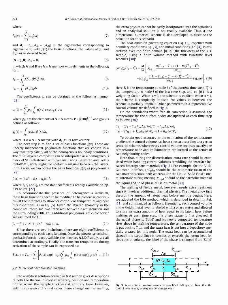
Fig. 3. Representative control volume in simplified 1-D system. Note that thecontrol volume may or may not be homogeneous.
2.2. Numerical heat transfer modeling
The analytical solution derived in last section gives descriptionsof both the thermal history at arbitrary position and temperatureprofile across the sample thickness at arbitrary time. However,with the presence of a first order phase change such as melting,
the extra physics cannot be easily incorporated into the equationsand an analytical solution is not readily available. Thus, a onedimensional numerical scheme is also developed to describe theactuation for this scenario.
The heat diffusion governing equation (Eq. (1)) together withboundary conditions (Eq. (3)) and initial conditions (Eq. (4)) is dis-cretized over the finite domain [0,9b] (the thickness of the RTCsample) using a finite volume method with two-time levelschemes [30]:
ðqCpÞef ðT i � T0i Þ ¼
DtDxðkiþ1
2Þ
ef
aðT iþ1 � T iÞ þ ð1� aÞðT0iþ1 � T0
i Þdxiþ1
2
"
�ðki�12Þ
ef
aðT i � T i�1Þ þ ð1� aÞðT0i � T0
i�1Þdxi�1
2
þ gefDx
#: ð16Þ
Here Ti is the temperature at node i of the current time step, T0i is
the temperature at node i of the last time step, and a 2 [0,1] is aweighting factor. When a = 0, the scheme is explicit; when a = 1,the scheme is completely implicit. For values in between, thescheme is partially implicit. Other parameters in a representativecontrol volume are defined in Fig. 3.
On the boundaries where free air convection is assumed, thetemperature for the surface nodes are updated at each time stepas follows [30]:
T0 ¼ ðT1 þ TairhairDx=kVÞ=ð1þ hairDx=kVÞ;TN ¼ ðTN�1 þ TairhairDx=kVÞ=ð1þ hairDx=kVÞ:
ð17Þ
To obtain good accuracy in the estimation of the temperaturegradient, the control volume has been chosen according to a vertexcentered scheme, where every control volume encloses exactly onetemperature node and its boundaries are located at the center oftwo neighboring nodes.
Note that, during the discretization, extra care should be exer-cised when handling control volumes straddling the interface be-tween heterogenous materials (Fig. 3). For example, for the VHB-Galinstan interface, (qCp)ef should be the arithmetic mean of thetwo materials contained; whereas, for the Liquid–Solid Field’s me-tal interface during melting, kiþ1
2;ef should be the harmonic mean of
the liquid and solid phase of Field’s metal [30].The melting of Field’s metal, however, needs extra treatment
since it involves additional thermal physics. The metal alloy firstabsorbs the amount of latent heat before melting begins. Here,we adopted the LHA method, which is described in detail in Ref.[11] and summarized as follows. Essentially, each control volumein the Field’s metal layer is labeled with a phase status and allowedto store an extra amount of heat equal to its latent heat beforemelting. At each time step, the phase status is first checked. Ifthe nodal phase is ‘Solid’ and its newly computed temperaturerises above its melting temperature, the temperature of the nodeis put back to Tmelt and the extra heat is put into a depository spe-cially created for this node. The extra heat can be accumulatedthrough the steps. Once it reaches or exceeds the latent heat forthis control volume, the label of the phase is changed from ‘Solid’
W.L. Shan et al. / International Journal of Heat and Mass Transfer 66 (2013) 271–278 275
to ‘Liquid’ and the exceeding part of the extra heat will bereassigned to increase the temperature of the liquid by a corre-sponding amount. When the phase status is liquid, or is solid butthe newly computed temperature is below the melting tempera-ture, the regular heat diffusion equation will be sufficient andthe phase status is kept the same.
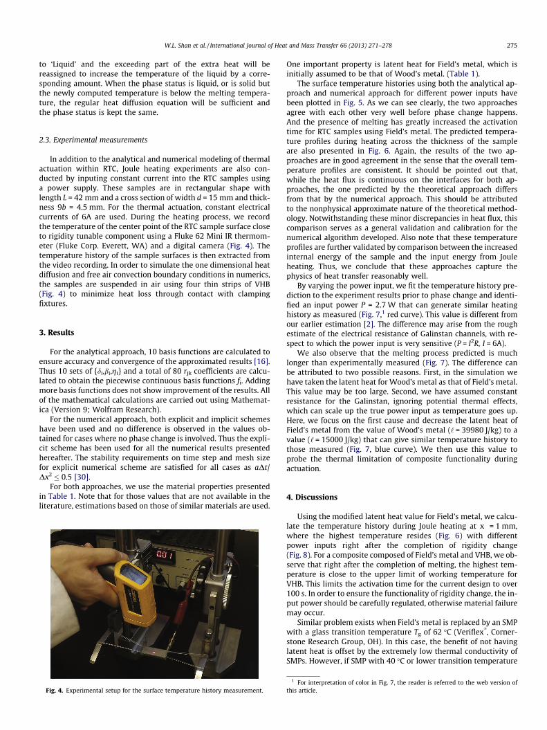
2.3. Experimental measurements
In addition to the analytical and numerical modeling of thermalactuation within RTC, Joule heating experiments are also con-ducted by inputing constant current into the RTC samples usinga power supply. These samples are in rectangular shape withlength L = 42 mm and a cross section of width d = 15 mm and thick-ness 9b = 4.5 mm. For the thermal actuation, constant electricalcurrents of 6A are used. During the heating process, we recordthe temperature of the center point of the RTC sample surface closeto rigidity tunable component using a Fluke 62 Mini IR thermom-eter (Fluke Corp. Everett, WA) and a digital camera (Fig. 4). Thetemperature history of the sample surfaces is then extracted fromthe video recording. In order to simulate the one dimensional heatdiffusion and free air convection boundary conditions in numerics,the samples are suspended in air using four thin strips of VHB(Fig. 4) to minimize heat loss through contact with clampingfixtures.
3. Results
For the analytical approach, 10 basis functions are calculated toensure accuracy and convergence of the approximated results [16].Thus 10 sets of {di,bi,gi} and a total of 80 rjk coefficients are calcu-lated to obtain the piecewise continuous basis functions fi. Addingmore basis functions does not show improvement of the results. Allof the mathematical calculations are carried out using Mathemat-ica (Version 9; Wolfram Research).
For the numerical approach, both explicit and implicit schemeshave been used and no difference is observed in the values ob-tained for cases where no phase change is involved. Thus the expli-cit scheme has been used for all the numerical results presentedhereafter. The stability requirements on time step and mesh sizefor explicit numerical scheme are satisfied for all cases as aDt/Dx2 � 0.5 [30].
For both approaches, we use the material properties presentedin Table 1. Note that for those values that are not available in theliterature, estimations based on those of similar materials are used.
Fig. 4. Experimental setup for the surface temperature history measurement.
One important property is latent heat for Field’s metal, which isinitially assumed to be that of Wood’s metal. (Table 1).
The surface temperature histories using both the analytical ap-proach and numerical approach for different power inputs havebeen plotted in Fig. 5. As we can see clearly, the two approachesagree with each other very well before phase change happens.And the presence of melting has greatly increased the activationtime for RTC samples using Field’s metal. The predicted tempera-ture profiles during heating across the thickness of the sampleare also presented in Fig. 6. Again, the results of the two ap-proaches are in good agreement in the sense that the overall tem-perature profiles are consistent. It should be pointed out that,while the heat flux is continuous on the interfaces for both ap-proaches, the one predicted by the theoretical approach differsfrom that by the numerical approach. This should be attributedto the nonphysical approximate nature of the theoretical method-ology. Notwithstanding these minor discrepancies in heat flux, thiscomparison serves as a general validation and calibration for thenumerical algorithm developed. Also note that these temperatureprofiles are further validated by comparison between the increasedinternal energy of the sample and the input energy from Jouleheating. Thus, we conclude that these approaches capture thephysics of heat transfer reasonably well.
By varying the power input, we fit the temperature history pre-diction to the experiment results prior to phase change and identi-fied an input power P = 2.7 W that can generate similar heatinghistory as measured (Fig. 7,1 red curve). This value is different fromour earlier estimation [2]. The difference may arise from the roughestimate of the electrical resistance of Galinstan channels, with re-spect to which the power input is very sensitive (P = I2R, I = 6A).
We also observe that the melting process predicted is muchlonger than experimentally measured (Fig. 7). The difference canbe attributed to two possible reasons. First, in the simulation wehave taken the latent heat for Wood’s metal as that of Field’s metal.This value may be too large. Second, we have assumed constantresistance for the Galinstan, ignoring potential thermal effects,which can scale up the true power input as temperature goes up.Here, we focus on the first cause and decrease the latent heat ofField’s metal from the value of Wood’s metal (‘ = 39980 J/kg) to avalue (‘ = 15000 J/kg) that can give similar temperature history tothose measured (Fig. 7, blue curve). We then use this value toprobe the thermal limitation of composite functionality duringactuation.
4. Discussions
Using the modified latent heat value for Field’s metal, we calcu-late the temperature history during Joule heating at x = 1 mm,where the highest temperature resides (Fig. 6) with differentpower inputs right after the completion of rigidity change(Fig. 8). For a composite composed of Field’s metal and VHB, we ob-serve that right after the completion of melting, the highest tem-perature is close to the upper limit of working temperature forVHB. This limits the activation time for the current design to over100 s. In order to ensure the functionality of rigidity change, the in-put power should be carefully regulated, otherwise material failuremay occur.
Similar problem exists when Field’s metal is replaced by an SMPwith a glass transition temperature Tg of 62 �C (Veriflex
�, Corner-
stone Research Group, OH). In this case, the benefit of not havinglatent heat is offset by the extremely low thermal conductivity ofSMPs. However, if SMP with 40 �C or lower transition temperature
1 For interpretation of color in Fig. 7, the reader is referred to the web version ofthis article.
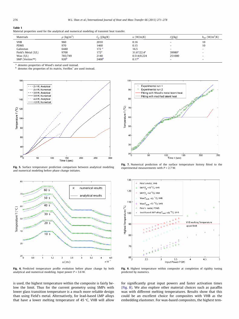
Table 1Material properties used for the analytical and numerical modeling of transient heat transfer.
Materials q (kg/m3) Cp (J/kg/K) j (W/m/K) ‘(J/kg) hair (W/m2/K)
VHB 960 2010 0.16 – 10PDMS 970 1460 0.15 – 10Galinstan 6440 172 a 16.5 – –Field’s Metal (S/L) 9700 172a 31.6a/22.4a 39980a –Wax (S/L) 785/749 2140 0.514/0.224 251000 –SMP (Veritex™) 920b 2400b 0.17b – –
a denotes properties of Wood’s metal used instead.b denotes the properties of its matrix, Veriflex
�are used instead.
Fig. 5. Surface temperature prediction comparison between analytical modelingand numerical modeling before phase change initiates.
Fig. 6. Predicted temperature profile evolution before phase change by bothanalytical and numerical modeling. Input power P = 3.6 W.
Fig. 7. Numerical prediction of the surface temperature history fitted to theexperimental measurements with P = 2.7 W.
Fig. 8. Highest temperature within composite at completion of rigidity tuningpredicted by numerics.
276 W.L. Shan et al. / International Journal of Heat and Mass Transfer 66 (2013) 271–278
is used, the highest temperature within the composite is fairly be-low the limit. Thus for the current geometry using SMPs withlower glass transition temperature is a much more reliable designthan using Field’s metal. Alternatively, for lead-based LMP alloysthat have a lower melting temperature of 45 �C, VHB will allow
for significantly great input powers and faster activation times(Fig. 8). We also explore other material choices such as paraffinwax with different melting temperatures. Results show that thiscould be an excellent choice for composites with VHB as theembedding elastomer. For wax-based composites, the highest tem-
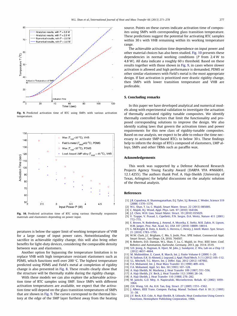
Fig. 9. Predicted activation time of RTC using SMPs with various activationtemperature.
Fig. 10. Predicted activation time of RTC using various thermally responsivematerials and elastomers depending on power input.
W.L. Shan et al. / International Journal of Heat and Mass Transfer 66 (2013) 271–278 277
peratures is below the upper limit of working temperature of VHBfor a large range of input power rates. Notwithstanding thesacrifice in achievable rigidity change, this will also bring otherbenefits for light-duty devices, considering the comparable densitybetween wax and elastomers.
Another option for bypassing the temperature limitation is toreplace VHB with high temperature resistant elastomers such asPDMS, which functions well over 200 �C. The highest temperaturepredicted using PDMS and Field’s metal at completion of rigiditychange is also presented in Fig. 8. These results clearly show thatthe structure will be thermally stable during the rigidity change.
With these models we can also explore the achievable activa-tion time of RTC samples using SMP. Since SMPs with differentactivation temperatures are available, we expect that the activa-tion time will depend on the glass transition temperatures of SMPsthat are shown in Fig. 9. The curves correspond to the thermal his-tory at the edge of the SMP layer furthest away from the heating
source. Points on these curves indicate activation time of compos-ites using SMPs with corresponding glass transition temperature.These predictions suggest the potential for activating RTC sampleswithin 30 s with VHB remaining within its working temperaturerange.
The achievable activation time dependence on input power andother material choices has also been studied. Fig. 10 presents thesedependencies in normal working conditions (P from 2.4 W to4.8 W). All data indicate a roughly 60 s threshold. Based on theseresults together with those shown in Fig. 9, in cases where sloweractivation is allowed and high performance is demanded, PDMS orother similar elastomers with Field’s metal is the most appropriatedesign. If fast activation is prioritized over drastic rigidity change,then SMPs with lower transition temperature and VHB arepreferable.
5. Concluding remarks
In this paper we have developed analytical and numerical mod-els along with experimental validation to investigate the actuationof thermally activated rigidity tunable composites. We identifythermally controlled factors that limit the functionality and pro-posed corresponding solutions to improve the design. We alsoidentify scaling laws that govern the activation times and powerrequirements for this new class of rigidity-tunable composites.Based on our analysis, we expect to be able to reduce the time nec-essary to activate SMP-based RTCs to below 30 s. These findingshelp to inform the design of RTCs composed of elastomers, LMP al-loys, SMPs and other TRMs such as paraffin wax.
Acknowledgements
This work was supported by a Defense Advanced ResearchProjects Agency Young Faculty Award (DARPA YFA #N66001.12.1.4255). The authors thank Prof. A. Haji-Sheikh (University ofTexas, Arlington) for helpful discussions on the analytic solutionof the thermal analysis.
References
[1] J.R. Capadona, K. Shanmuganathan, D.J. Tyler, S.J. Rowan, C. Weder, Science 319(2008) 1370–1374.
[2] W.L. Shan, T. Lu, C. Majidi, Smart Mater. Struct. 22 (2013) 085005.[3] C. Majidi, R.J. Wood, Appl. Phys. Lett. 97 (2010) 164104.[4] J.Z. Chen, W.H. Liao, Smart Mater. Struct. 19 (2010) 035029.[5] V. Trappe, V. Prasad, L. Cipelletti, P.N. Sergre, D.A. Weitz, Nature 411 (2001)
772–775.[6] E. Brown, N. Rodenberg, J. Amend, A. Mozeika, E. Steltz, M.R. Zakin, H. Lipson,
H.M. Jaeger, Proc. Nat. Acad. Sci. USA 107 (2010) 18809–18814.[7] G. McKnight, R. Doty, A. Keefe, G. Herrera, C. Henry, J. Intell. Mater. Syst. Struct.
21 (2010) 1783–1793.[8] W.W. Clark, J.C. Brigham, C. Mo, S. Joshi, Proc. SPIE Indust. Commercial Appl.
Smart Struct., San Diego, CA, 2010, 764507.[9] R. Roberts, D.D. Damian, W.L. Shan, T. Lu, C. Majidi, in: Proc. IEEE Inter. Conf.
Robotics and Automation, Karlsruhe, Germany, 2013, pp. 3514–3519.[10] S.H. Jeong, A. Hagman, K. Hjort, M. Jobs, J. Sundqvist, Z. Wu, Lab on a Chip 12
(2012) 4657–4664.[11] M. Muhieddine, E. Canot, R. March, Int. J. Finite Volume 6 (2009) 1–20.[12] N. Sadoun, E.K. Si-Ahmed, J. Legrand, J. Appl. Fluid Mech. 5 (1) (2012) 105–112.[13] S.L. Mitchell, T.G. Myers, Int. J. Differ. Equ. 2012 (2012) 187902.[14] F.A. Mohamed, Int. J. Heat Mass Transfer 33 (1990) 409–416.[15] F.A. Mohamed, Appl. Sci. Res. 50 (1993) 107–128.[16] A. Haji-Sheikh, M. Mashena, J. Heat Transfer 109 (1987) 551–556.[17] A. Haji-Sheikh, J.V. Beck, J. Heat Transfer 112 (1990) 28–34.[18] A. Haji-Sheikh, J. Heat Transfer 110 (1988) 276–282.[19] M. Janicki, G.D. Mey, A. Napieralski, Microelectron. Reliab. 42 (2002) 1059–
1064.[20] Z.H. Wang, S.K. Au, K.H. Tan, Eng. Struct. 27 (2005) 1551–1562.[21] J. Albers, IEEE Trans. Compon. Packag. Manuf. Technol.–Part A 18 (1) (1995)
31–38.[22] J.V. Beck, K.D. Cole, A. Haji-Sheikh, B. Litkouhi, Heat Conduction Using Green’s
Functions, Hemisphere Publishing Corporation, 1984.

278 W.L. Shan et al. / International Journal of Heat and Mass Transfer 66 (2013) 271–278
[23] H.S. Carslaw, J.C. Jaeger, Conduction of Heat in Solids, Oxford: Clarendon Press,1959.
[24] K.D. Cole, J.V. Beck, A. Haji-Sheikh, B. Litkouhi, Heat Conduction Using Green’sFunctions, 2nd ed., CRC/Taylor and Francis, 2011.
[25] H. Schlichting, K. Gersten, Boundary Layer Theory, Springer, Berlin, Germany,2000.
[26] T.R. Goodman, Trans. ASME 80 (1958) 335–342.
[27] V.R. Voller, M. Cross, Int. J. Heat Mass Transfer 24 (1981) 545–556.[28] V.R. Voller, M. Cross, N.C. Markatos, Int. J. Numer. Meth. Eng. 24 (1987) 184–
271.[29] C. Bonacina, G. Comini, A. Fasano, M. Primicerio, Int. J. Heat Mass Transfer 16
(1973) 1825–1832.[30] W. Tao, Numerical Heat Transfer, 2nd ed., Xi’an Jiaotong University Press,
Xi’an, China, 2001.


![+1cm[width=30mm]logo.pdf +1cm MHD Tangent Hyperbolic ... Qamar.pdf · CERTIFICATE OF APPROVAL MHD Tangent Hyperbolic Nano uid Past a Stretching Sheet with the E ect of Joule Heating](https://img.pdfslide.net/doc/110x75/5d57042188c99392138b8fe5/1cmwidth30mmlogopdf-1cm-mhd-tangent-hyperbolic-qamarpdf-certificate.jpg)