Embed Size (px)
Citation preview
at SciVerse ScienceDirect
International Journal of Pressure Vessels and Piping 92 (2012) 11e18
Contents lists available
International Journal of Pressure Vessels and Piping
journal homepage: www.elsevier .com/locate/ i jpvp
Review
Plastic load evaluation for a fixed tube sheet heat exchanger subject toproportional loading
Khosrow Behseta*, Donald Mackenzie, Robert HamiltonDepartment of Mechanical Engineering, University of Strathclyde, Glasgow G1 1XJ, Scotland, UK
a r t i c l e i n f o
Article history:Received 22 April 2010Received in revised form5 December 2011Accepted 5 December 2011
Keywords:Plastic loadCurvature of plastic workLoadedeformationMaterial hardeningSmall deformationLarge deformation
* Corresponding author.E-mail address: [email protected] (K. Behseta
0308-0161/$ e see front matter � 2011 Elsevier Ltd.doi:10.1016/j.ijpvp.2011.12.002
a b s t r a c t
The plastic load of pressurised components can be calculated based on both the twice elastic slope andtangent methods. Both methods are problematic since they rely on parameters that are localised andtherefore have a strong dependency on the gradient of the stressestrain diagram in the plastic region.The criterion of curvature of plastic work is a suitable replacement for the above techniques. This methodcalculates total plastic work done on the structure and relates its change to the curvature of the load-plastic work plot. In this work the plastic load has been calculated for a fixed tube sheet exchangeraccording to curvature criteria using various hardening scenarios. Plastic loads calculated by othermethods also have been reported. It has been indicated that tube sheet thickness calculated according tothe classical ASME procedure can be significantly reduced when based on the curvature criteria.
� 2011 Elsevier Ltd. All rights reserved.
1. Introduction
Heat exchanger tube sheets are a significant expense in powerand process plant, where large numbers of heat exchangers may beused. The cost of a tube sheet is dependent on the basic thicknessrequired to satisfy safety and functional considerations, not only interms of material cost but also the added manufacturing costsassociated with machining, drilling, welding and NDT. These costsrise greatly as tube sheet thickness increases and it is financiallyadvantageous to minimise the required tube sheet thickness at thedesign stage.
Conventional tube sheet design is based on modified elasticplate bending theory, in which the perforated tube sheet is treatedas a thin homogeneous plate with modified material propertiesused to simulate the structural effect of the perforations. In pres-sure vessel Design by Formula procedures, for example ASME VIIIDiv 1 and Div 2 [1,2], design factors are applied to the solid platemodel to account for exchanger type, tube pitch and othergeometrical information. The conventional approach is safe andfunctionally effective but may lead to over-conservative designs inwhich the plate thickness is greater than that required to safelycontain the pressurised fluids in the heat exchanger. This
).
All rights reserved.
conservatism can be reduced by basing the design on a moredetailed stress analysis of the component through application ofCode Design by Analysis (DBA) procedures. Codes such as ASME III[3], ASME VIII Div 2 and EN13445 [4] provide methodologies fordesign based on both elastic and inelastic analysis.
Fixed tube sheet exchangers are subject to a steady-state steady-flow loading during their normal operation and criteria of sched-uled start-up to full shut-down, they also are also subject to anemergency shut-down mode. This work is based on the steady-state steady-flow mode and possible fluctuations in operatingpressure and operating temperature from steady-state operationare not considered in this work, such a notion is treated in a sepa-rate paper dealing with fatigue characteristics of the tube sheetwhich encompasses the effect of above variations.
It should be further noted that tube sheet and reactors areprotected against excess fluctuations and large variations in pres-sure and temperature from normal operating mode, fluctuations inpressure or temperature occurs not from design conditions butfrom operating parameters. Tube sheet and reactors are protectedby continuous monitoring of the flow parameters both on the shelland on the tube side, shut-down logic will be activated if pre-setparameters are exceed (data sheet in Ref. [5]). This means thetube sheet will never experience non proportional loading, i.e.,a rise in one parameter, for example pressure, in expense of thedrop in the other one, for example temperature loads, beyond itsprotected range.
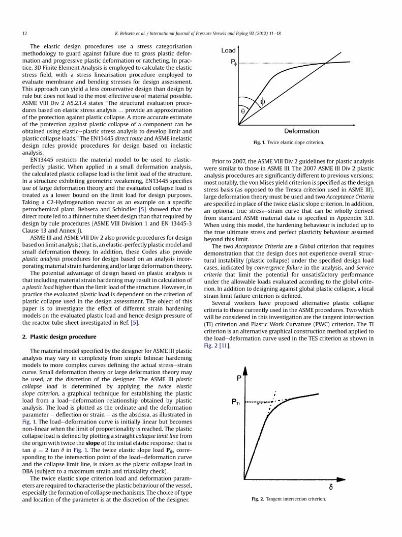
Fig. 1. Twice elastic slope criterion.
Fig. 2. Tangent intersection criterion.
K. Behseta et al. / International Journal of Pressure Vessels and Piping 92 (2012) 11e1812
The elastic design procedures use a stress categorisationmethodology to guard against failure due to gross plastic defor-mation and progressive plastic deformation or ratcheting. In prac-tice, 3D Finite Element Analysis is employed to calculate the elasticstress field, with a stress linearisation procedure employed toevaluate membrane and bending stresses for design assessment.This approach can yield a less conservative design than design byrule but does not lead to the most effective use of material possible.ASME VIII Div 2 A5.2.1.4 states “The structural evaluation proce-dures based on elastic stress analysis . provide an approximationof the protection against plastic collapse. A more accurate estimateof the protection against plastic collapse of a component can beobtained using elasticeplastic stress analysis to develop limit andplastic collapse loads.” The EN13445 direct route and ASME inelasticdesign rules provide procedures for design based on inelasticanalysis.
EN13445 restricts the material model to be used to elastic-perfectly plastic. When applied in a small deformation analysis,the calculated plastic collapse load is the limit load of the structure.In a structure exhibiting geometric weakening, EN13445 specifiesuse of large deformation theory and the evaluated collapse load istreated as a lower bound on the limit load for design purposes.Taking a C2-Hydrogenation reactor as an example on a specificpetrochemical plant, Behseta and Schindler [5] showed that thedirect route led to a thinner tube sheet design than that required bydesign by rule procedures (ASME VIII Division 1 and EN 13445-3Clause 13 and Annex J).
ASME III and ASME VIII Div 2 also provide procedures for designbasedon limit analysis; that is, an elastic-perfectly plasticmodel andsmall deformation theory. In addition, these Codes also provideplastic analysis procedures for design based on an analysis incor-poratingmaterial strain hardening and/or large deformation theory.
The potential advantage of design based on plastic analysis isthat includingmaterial strain hardeningmay result in calculation ofa plastic load higher than the limit load of the structure. However, inpractice the evaluated plastic load is dependent on the criterion ofplastic collapse used in the design assessment. The object of thispaper is to investigate the effect of different strain hardeningmodels on the evaluated plastic load and hence design pressure ofthe reactor tube sheet investigated in Ref. [5].
2. Plastic design procedure
Thematerial model specified by the designer for ASME III plasticanalysis may vary in complexity from simple bilinear hardeningmodels to more complex curves defining the actual stressestraincurve. Small deformation theory or large deformation theory maybe used, at the discretion of the designer. The ASME III plasticcollapse load is determined by applying the twice elasticslope criterion, a graphical technique for establishing the plasticload from a loadedeformation relationship obtained by plasticanalysis. The load is plotted as the ordinate and the deformationparameter e deflection or strain e as the abscissa, as illustrated inFig. 1. The loadedeformation curve is initially linear but becomesnon-linear when the limit of proportionality is reached. The plasticcollapse load is defined by plotting a straight collapse limit line fromthe originwith twice the slope of the initial elastic response: that istan f ¼ 2 tan q in Fig. 1. The twice elastic slope load Pf, corre-sponding to the intersection point of the loadedeformation curveand the collapse limit line, is taken as the plastic collapse load inDBA (subject to a maximum strain and triaxiality check).
The twice elastic slope criterion load and deformation param-eters are required to characterise the plastic behaviour of the vessel,especially the formation of collapsemechanisms. The choice of typeand location of the parameter is at the discretion of the designer.
Prior to 2007, the ASME VIII Div 2 guidelines for plastic analysiswere similar to those in ASME III. The 2007 ASME III Div 2 plasticanalysis procedures are significantly different to previous versions;most notably, the vonMises yield criterion is specified as the designstress basis (as opposed to the Tresca criterion used in ASME III),large deformation theory must be used and two Acceptance Criteriaare specified in place of the twice elastic slope criterion. In addition,an optional true stressestrain curve that can be wholly derivedfrom standard ASME material data is specified in Appendix 3.D.When using this model, the hardening behaviour is included up tothe true ultimate stress and perfect plasticity behaviour assumedbeyond this limit.
The two Acceptance Criteria are a Global criterion that requiresdemonstration that the design does not experience overall struc-tural instability (plastic collapse) under the specified design loadcases, indicated by convergence failure in the analysis, and Servicecriteria that limit the potential for unsatisfactory performanceunder the allowable loads evaluated according to the global crite-rion. In addition to designing against global plastic collapse, a localstrain limit failure criterion is defined.
Several workers have proposed alternative plastic collapsecriteria to those currently used in the ASME procedures. Twowhichwill be considered in this investigation are the tangent intersection(TI) criterion and Plastic Work Curvature (PWC) criterion. The TIcriterion is an alternative graphical construction method applied tothe loadedeformation curve used in the TES criterion as shown inFig. 2 [11].
K. Behseta et al. / International Journal of Pressure Vessels and Piping 92 (2012) 11e18 13
The PWC criterion is based on consideration of the plasticdissipation as load increases post-yield. This criterion was devel-oped from an earlier plastic work criterion proposed by Muscatet al. [6]. The concept of plastic work curvature (PWC) [9] identifiesthe plastic load by considering the curvature of the load-plasticwork curve. The criterion is illustrated in Fig. 3 shows a graph ofload versus plastic work and a graph of curvature versus Plasticwork plotted on the same diagram.
The curvature identifies the rate of change of plastic defor-mation. In the initial of elastic region, plastic work is zero, in upperstages of the elastic region, small plasticisation occurs with verysmall curvature. Around yield the curvature starts to increaserapidly until it reaches its maximum value. A further increase inload reduces the curvature due to the post yielding behaviourand stress redistribution. The load corresponding to the peakcurvature is the plastic load. Domination of gross plastic defor-mation occurs at a loading corresponding to about 10% of themaximum curvature. In other words, curvature of plastic workcriteria is quite unique as the procedure depends solely on thetotal plastic work done on the structure. In this criterion, load,plastic work and curvature of plastic work are simultaneouslycoupled and therefore the load causing peak curvature can beidentified. The peak curvature indicates the start of gross plasticdeformation.
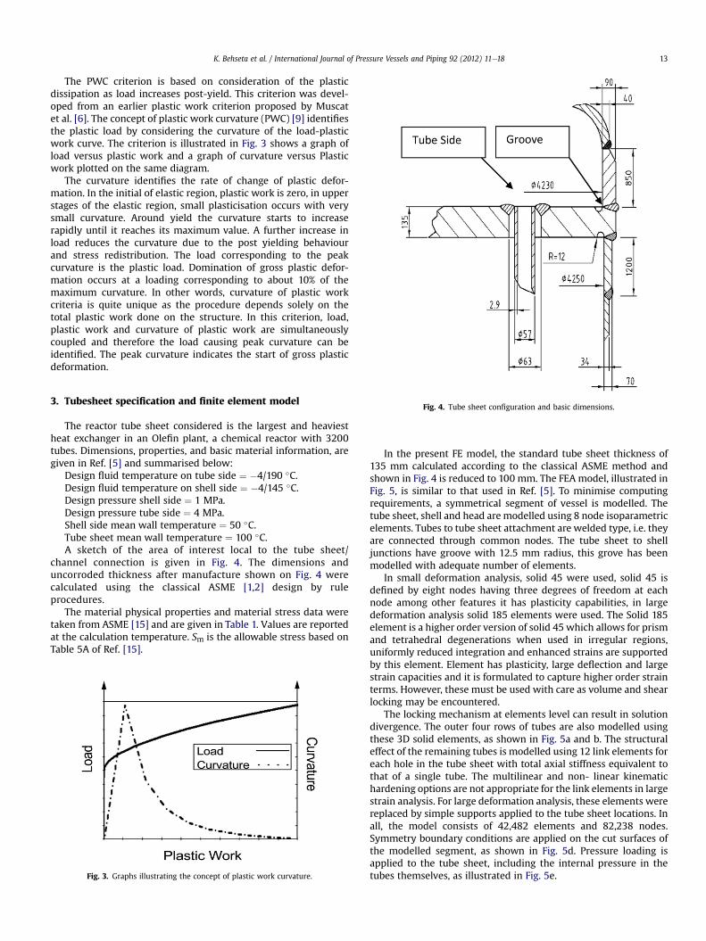
Fig. 4. Tube sheet configuration and basic dimensions.
3. Tubesheet specification and finite element modelThe reactor tube sheet considered is the largest and heaviestheat exchanger in an Olefin plant, a chemical reactor with 3200tubes. Dimensions, properties, and basic material information, aregiven in Ref. [5] and summarised below:
Design fluid temperature on tube side ¼ �4/190 �C.Design fluid temperature on shell side ¼ �4/145 �C.Design pressure shell side ¼ 1 MPa.Design pressure tube side ¼ 4 MPa.Shell side mean wall temperature ¼ 50 �C.Tube sheet mean wall temperature ¼ 100 �C.A sketch of the area of interest local to the tube sheet/
channel connection is given in Fig. 4. The dimensions anduncorroded thickness after manufacture shown on Fig. 4 werecalculated using the classical ASME [1,2] design by ruleprocedures.
The material physical properties and material stress data weretaken from ASME [15] and are given in Table 1. Values are reportedat the calculation temperature. Sm is the allowable stress based onTable 5A of Ref. [15].
Fig. 3. Graphs illustrating the concept of plastic work curvature.
In the present FE model, the standard tube sheet thickness of135 mm calculated according to the classical ASME method andshown in Fig. 4 is reduced to 100 mm. The FEA model, illustrated inFig. 5, is similar to that used in Ref. [5]. To minimise computingrequirements, a symmetrical segment of vessel is modelled. Thetube sheet, shell and head are modelled using 8 node isoparametricelements. Tubes to tube sheet attachment are welded type, i.e. theyare connected through common nodes. The tube sheet to shelljunctions have groove with 12.5 mm radius, this grove has beenmodelled with adequate number of elements.
In small deformation analysis, solid 45 were used, solid 45 isdefined by eight nodes having three degrees of freedom at eachnode among other features it has plasticity capabilities, in largedeformation analysis solid 185 elements were used. The Solid 185element is a higher order version of solid 45 which allows for prismand tetrahedral degenerations when used in irregular regions,uniformly reduced integration and enhanced strains are supportedby this element. Element has plasticity, large deflection and largestrain capacities and it is formulated to capture higher order strainterms. However, these must be used with care as volume and shearlocking may be encountered.
The locking mechanism at elements level can result in solutiondivergence. The outer four rows of tubes are also modelled usingthese 3D solid elements, as shown in Fig. 5a and b. The structuraleffect of the remaining tubes is modelled using 12 link elements foreach hole in the tube sheet with total axial stiffness equivalent tothat of a single tube. The multilinear and non- linear kinematichardening options are not appropriate for the link elements in largestrain analysis. For large deformation analysis, these elements werereplaced by simple supports applied to the tube sheet locations. Inall, the model consists of 42,482 elements and 82,238 nodes.Symmetry boundary conditions are applied on the cut surfaces ofthe modelled segment, as shown in Fig. 5d. Pressure loading isapplied to the tube sheet, including the internal pressure in thetubes themselves, as illustrated in Fig. 5e.
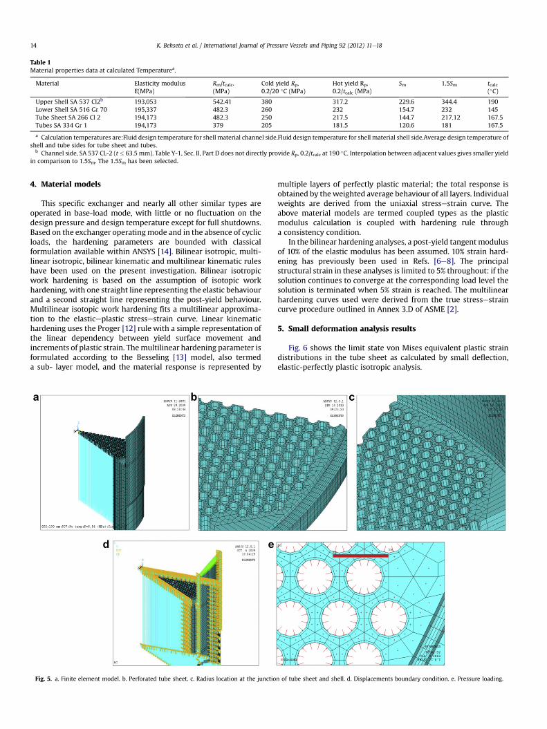
Table 1Material properties data at calculated Temperaturea.
Material Elasticity modulusE(MPa)
Rm/tcalc.(MPa)
Cold yield Rp,0.2/20 �C (MPa)
Hot yield Rp,0.2/tcalc (MPa)
Sm 1.5Sm tcalc(�C)
Upper Shell SA 537 Cl2b 193,053 542.41 380 317.2 229.6 344.4 190Lower Shell SA 516 Gr 70 195,337 482.3 260 232 154.7 232 145Tube Sheet SA 266 Cl 2 194,173 482.3 250 217.5 144.7 217.12 167.5Tubes SA 334 Gr 1 194,173 379 205 181.5 120.6 181 167.5
a Calculation temperatures are:Fluid design temperature for shell material channel side.Fluid design temperature for shell material shell side.Average design temperature ofshell and tube sides for tube sheet and tubes.
b Channel side, SA 537 CL-2 (t� 63.5 mm). Table Y-1, Sec. II, Part D does not directly provide Rp, 0.2/tcalc at 190 �C. Interpolation between adjacent values gives smaller yieldin comparison to 1.5Sm. The 1.5Sm has been selected.
K. Behseta et al. / International Journal of Pressure Vessels and Piping 92 (2012) 11e1814
4. Material models
This specific exchanger and nearly all other similar types areoperated in base-load mode, with little or no fluctuation on thedesign pressure and design temperature except for full shutdowns.Based on the exchanger operatingmode and in the absence of cyclicloads, the hardening parameters are bounded with classicalformulation available within ANSYS [14]. Bilinear isotropic, multi-linear isotropic, bilinear kinematic and multilinear kinematic ruleshave been used on the present investigation. Bilinear isotropicwork hardening is based on the assumption of isotopic workhardening, with one straight line representing the elastic behaviourand a second straight line representing the post-yield behaviour.Multilinear isotopic work hardening fits a multilinear approxima-tion to the elasticeplastic stressestrain curve. Linear kinematichardening uses the Proger [12] rule with a simple representation ofthe linear dependency between yield surface movement andincrements of plastic strain. Themultilinear hardening parameter isformulated according to the Besseling [13] model, also termeda sub- layer model, and the material response is represented by
Fig. 5. a. Finite element model. b. Perforated tube sheet. c. Radius location at the junctio
multiple layers of perfectly plastic material; the total response isobtained by theweighted average behaviour of all layers. Individualweights are derived from the uniaxial stressestrain curve. Theabove material models are termed coupled types as the plasticmodulus calculation is coupled with hardening rule througha consistency condition.
In the bilinear hardening analyses, a post-yield tangent modulusof 10% of the elastic modulus has been assumed. 10% strain hard-ening has previously been used in Refs. [6e8]. The principalstructural strain in these analyses is limited to 5% throughout: if thesolution continues to converge at the corresponding load level thesolution is terminated when 5% strain is reached. The multilinearhardening curves used were derived from the true stressestraincurve procedure outlined in Annex 3.D of ASME [2].
5. Small deformation analysis results
Fig. 6 shows the limit state von Mises equivalent plastic straindistributions in the tube sheet as calculated by small deflection,elastic-perfectly plastic isotropic analysis.
n of tube sheet and shell. d. Displacements boundary condition. e. Pressure loading.
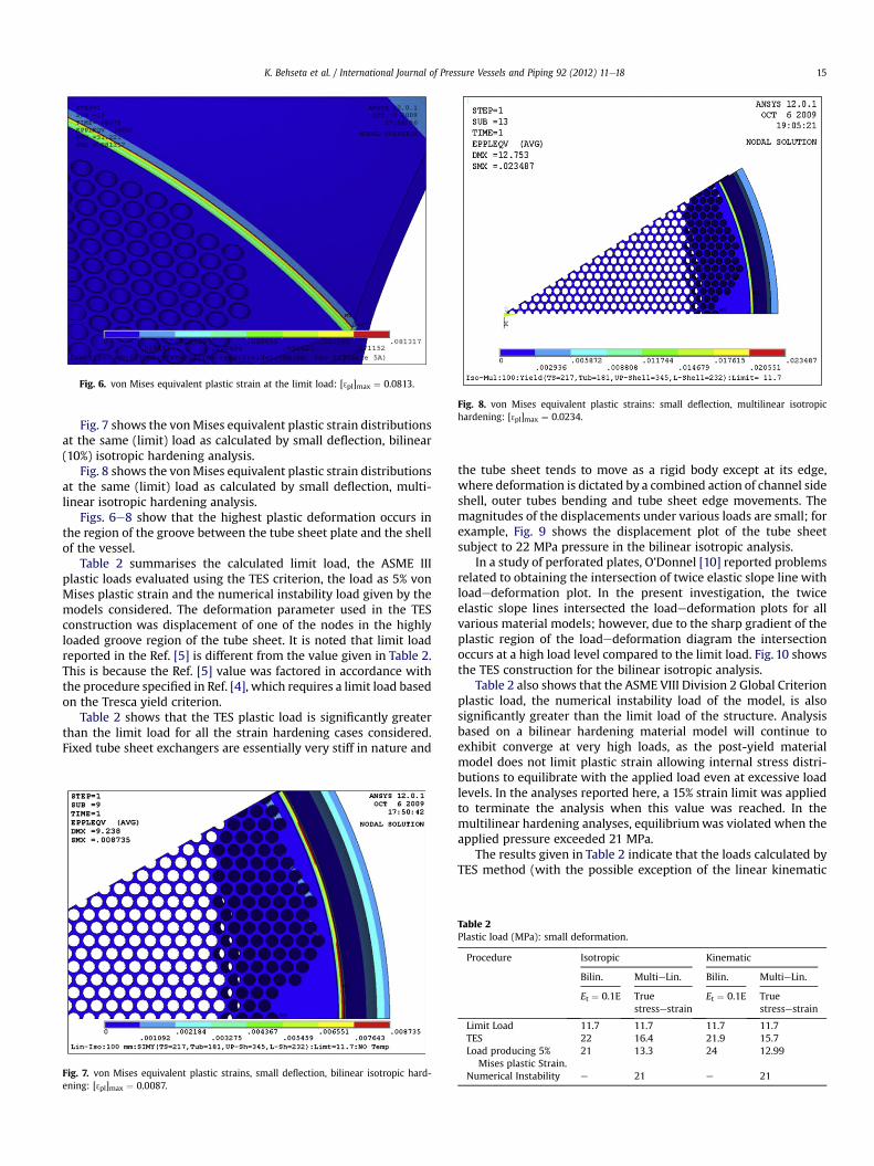
Fig. 8. von Mises equivalent plastic strains: small deflection, multilinear isotropichardening: [ 3pl]max ¼ 0.0234.
Fig. 6. von Mises equivalent plastic strain at the limit load: [ 3pl]max ¼ 0.0813.
K. Behseta et al. / International Journal of Pressure Vessels and Piping 92 (2012) 11e18 15
Fig. 7 shows the vonMises equivalent plastic strain distributionsat the same (limit) load as calculated by small deflection, bilinear(10%) isotropic hardening analysis.
Fig. 8 shows the vonMises equivalent plastic strain distributionsat the same (limit) load as calculated by small deflection, multi-linear isotropic hardening analysis.
Figs. 6e8 show that the highest plastic deformation occurs inthe region of the groove between the tube sheet plate and the shellof the vessel.
Table 2 summarises the calculated limit load, the ASME IIIplastic loads evaluated using the TES criterion, the load as 5% vonMises plastic strain and the numerical instability load given by themodels considered. The deformation parameter used in the TESconstruction was displacement of one of the nodes in the highlyloaded groove region of the tube sheet. It is noted that limit loadreported in the Ref. [5] is different from the value given in Table 2.This is because the Ref. [5] value was factored in accordance withthe procedure specified in Ref. [4], which requires a limit load basedon the Tresca yield criterion.
Table 2 shows that the TES plastic load is significantly greaterthan the limit load for all the strain hardening cases considered.Fixed tube sheet exchangers are essentially very stiff in nature and
Fig. 7. von Mises equivalent plastic strains, small deflection, bilinear isotropic hard-ening: [ 3pl]max ¼ 0.0087.
the tube sheet tends to move as a rigid body except at its edge,where deformation is dictated by a combined action of channel sideshell, outer tubes bending and tube sheet edge movements. Themagnitudes of the displacements under various loads are small; forexample, Fig. 9 shows the displacement plot of the tube sheetsubject to 22 MPa pressure in the bilinear isotropic analysis.
In a study of perforated plates, O’Donnel [10] reported problemsrelated to obtaining the intersection of twice elastic slope line withloadedeformation plot. In the present investigation, the twiceelastic slope lines intersected the loadedeformation plots for allvarious material models; however, due to the sharp gradient of theplastic region of the loadedeformation diagram the intersectionoccurs at a high load level compared to the limit load. Fig. 10 showsthe TES construction for the bilinear isotropic analysis.
Table 2 also shows that the ASME VIII Division 2 Global Criterionplastic load, the numerical instability load of the model, is alsosignificantly greater than the limit load of the structure. Analysisbased on a bilinear hardening material model will continue toexhibit converge at very high loads, as the post-yield materialmodel does not limit plastic strain allowing internal stress distri-butions to equilibrate with the applied load even at excessive loadlevels. In the analyses reported here, a 15% strain limit was appliedto terminate the analysis when this value was reached. In themultilinear hardening analyses, equilibriumwas violated when theapplied pressure exceeded 21 MPa.
The results given in Table 2 indicate that the loads calculated byTES method (with the possible exception of the linear kinematic
Table 2Plastic load (MPa): small deformation.
Procedure Isotropic Kinematic
Bilin. MultieLin. Bilin. MultieLin.
Et ¼ 0.1E Truestressestrain
Et ¼ 0.1E Truestressestrain
Limit Load 11.7 11.7 11.7 11.7TES 22 16.4 21.9 15.7Load producing 5%
Mises plastic Strain.21 13.3 24 12.99
Numerical Instability e 21 e 21
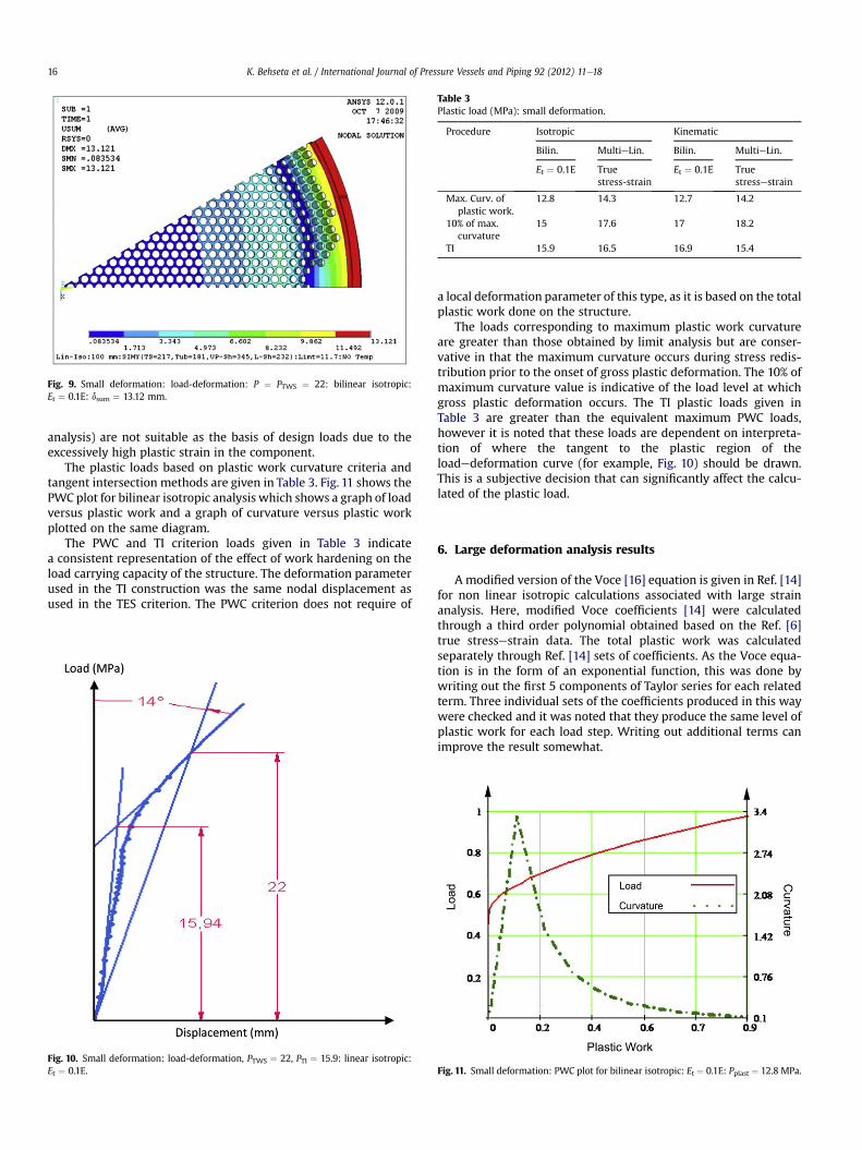
Fig. 9. Small deformation: load-deformation: P ¼ PTWS ¼ 22: bilinear isotropic:Et ¼ 0.1E: dsum ¼ 13.12 mm.
Table 3Plastic load (MPa): small deformation.
Procedure Isotropic Kinematic
Bilin. MultieLin. Bilin. MultieLin.
Et ¼ 0.1E Truestress-strain
Et ¼ 0.1E Truestressestrain
Max. Curv. ofplastic work.
12.8 14.3 12.7 14.2
10% of max.curvature
15 17.6 17 18.2
TI 15.9 16.5 16.9 15.4
K. Behseta et al. / International Journal of Pressure Vessels and Piping 92 (2012) 11e1816
analysis) are not suitable as the basis of design loads due to theexcessively high plastic strain in the component.
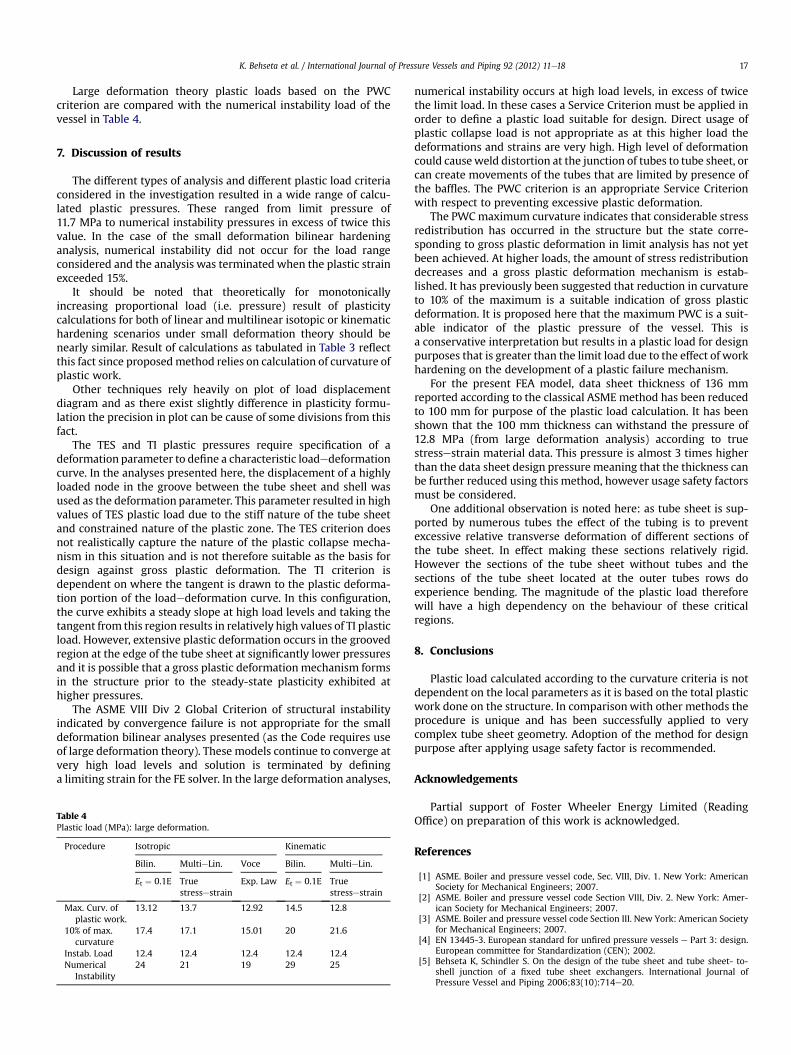
The plastic loads based on plastic work curvature criteria andtangent intersection methods are given in Table 3. Fig. 11 shows thePWC plot for bilinear isotropic analysis which shows a graph of loadversus plastic work and a graph of curvature versus plastic workplotted on the same diagram.
The PWC and TI criterion loads given in Table 3 indicatea consistent representation of the effect of work hardening on theload carrying capacity of the structure. The deformation parameterused in the TI construction was the same nodal displacement asused in the TES criterion. The PWC criterion does not require of
Fig. 10. Small deformation: load-deformation, PTWS ¼ 22, PTI ¼ 15.9: linear isotropic:Et ¼ 0.1E.
a local deformation parameter of this type, as it is based on the totalplastic work done on the structure.
The loads corresponding to maximum plastic work curvatureare greater than those obtained by limit analysis but are conser-vative in that the maximum curvature occurs during stress redis-tribution prior to the onset of gross plastic deformation. The 10% ofmaximum curvature value is indicative of the load level at whichgross plastic deformation occurs. The TI plastic loads given inTable 3 are greater than the equivalent maximum PWC loads,however it is noted that these loads are dependent on interpreta-tion of where the tangent to the plastic region of theloadedeformation curve (for example, Fig. 10) should be drawn.This is a subjective decision that can significantly affect the calcu-lated of the plastic load.
6. Large deformation analysis results
A modified version of the Voce [16] equation is given in Ref. [14]for non linear isotropic calculations associated with large strainanalysis. Here, modified Voce coefficients [14] were calculatedthrough a third order polynomial obtained based on the Ref. [6]true stressestrain data. The total plastic work was calculatedseparately through Ref. [14] sets of coefficients. As the Voce equa-tion is in the form of an exponential function, this was done bywriting out the first 5 components of Taylor series for each relatedterm. Three individual sets of the coefficients produced in this waywere checked and it was noted that they produce the same level ofplastic work for each load step. Writing out additional terms canimprove the result somewhat.
Fig. 11. Small deformation: PWC plot for bilinear isotropic: Et ¼ 0.1E: Pplast ¼ 12.8 MPa.
K. Behseta et al. / International Journal of Pressure Vessels and Piping 92 (2012) 11e18 17
Large deformation theory plastic loads based on the PWCcriterion are compared with the numerical instability load of thevessel in Table 4.
7. Discussion of results
The different types of analysis and different plastic load criteriaconsidered in the investigation resulted in a wide range of calcu-lated plastic pressures. These ranged from limit pressure of11.7 MPa to numerical instability pressures in excess of twice thisvalue. In the case of the small deformation bilinear hardeninganalysis, numerical instability did not occur for the load rangeconsidered and the analysis was terminated when the plastic strainexceeded 15%.
It should be noted that theoretically for monotonicallyincreasing proportional load (i.e. pressure) result of plasticitycalculations for both of linear and multilinear isotopic or kinematichardening scenarios under small deformation theory should benearly similar. Result of calculations as tabulated in Table 3 reflectthis fact since proposedmethod relies on calculation of curvature ofplastic work.
Other techniques rely heavily on plot of load displacementdiagram and as there exist slightly difference in plasticity formu-lation the precision in plot can be cause of some divisions from thisfact.
The TES and TI plastic pressures require specification of adeformation parameter to define a characteristic loadedeformationcurve. In the analyses presented here, the displacement of a highlyloaded node in the groove between the tube sheet and shell wasused as the deformation parameter. This parameter resulted in highvalues of TES plastic load due to the stiff nature of the tube sheetand constrained nature of the plastic zone. The TES criterion doesnot realistically capture the nature of the plastic collapse mecha-nism in this situation and is not therefore suitable as the basis fordesign against gross plastic deformation. The TI criterion isdependent on where the tangent is drawn to the plastic deforma-tion portion of the loadedeformation curve. In this configuration,the curve exhibits a steady slope at high load levels and taking thetangent from this region results in relatively high values of TI plasticload. However, extensive plastic deformation occurs in the groovedregion at the edge of the tube sheet at significantly lower pressuresand it is possible that a gross plastic deformationmechanism formsin the structure prior to the steady-state plasticity exhibited athigher pressures.
The ASME VIII Div 2 Global Criterion of structural instabilityindicated by convergence failure is not appropriate for the smalldeformation bilinear analyses presented (as the Code requires useof large deformation theory). These models continue to converge atvery high load levels and solution is terminated by defininga limiting strain for the FE solver. In the large deformation analyses,
Table 4Plastic load (MPa): large deformation.
Procedure Isotropic Kinematic
Bilin. MultieLin. Voce Bilin. MultieLin.
Et ¼ 0.1E Truestressestrain
Exp. Law Et ¼ 0.1E Truestressestrain
Max. Curv. ofplastic work.
13.12 13.7 12.92 14.5 12.8
10% of max.curvature
17.4 17.1 15.01 20 21.6
Instab. Load 12.4 12.4 12.4 12.4 12.4Numerical
Instability24 21 19 29 25
numerical instability occurs at high load levels, in excess of twicethe limit load. In these cases a Service Criterion must be applied inorder to define a plastic load suitable for design. Direct usage ofplastic collapse load is not appropriate as at this higher load thedeformations and strains are very high. High level of deformationcould causeweld distortion at the junction of tubes to tube sheet, orcan create movements of the tubes that are limited by presence ofthe baffles. The PWC criterion is an appropriate Service Criterionwith respect to preventing excessive plastic deformation.
The PWCmaximum curvature indicates that considerable stressredistribution has occurred in the structure but the state corre-sponding to gross plastic deformation in limit analysis has not yetbeen achieved. At higher loads, the amount of stress redistributiondecreases and a gross plastic deformation mechanism is estab-lished. It has previously been suggested that reduction in curvatureto 10% of the maximum is a suitable indication of gross plasticdeformation. It is proposed here that the maximum PWC is a suit-able indicator of the plastic pressure of the vessel. This isa conservative interpretation but results in a plastic load for designpurposes that is greater than the limit load due to the effect of workhardening on the development of a plastic failure mechanism.
For the present FEA model, data sheet thickness of 136 mmreported according to the classical ASME method has been reducedto 100 mm for purpose of the plastic load calculation. It has beenshown that the 100 mm thickness can withstand the pressure of12.8 MPa (from large deformation analysis) according to truestressestrain material data. This pressure is almost 3 times higherthan the data sheet design pressure meaning that the thickness canbe further reduced using this method, however usage safety factorsmust be considered.
One additional observation is noted here: as tube sheet is sup-ported by numerous tubes the effect of the tubing is to preventexcessive relative transverse deformation of different sections ofthe tube sheet. In effect making these sections relatively rigid.However the sections of the tube sheet without tubes and thesections of the tube sheet located at the outer tubes rows doexperience bending. The magnitude of the plastic load thereforewill have a high dependency on the behaviour of these criticalregions.
8. Conclusions
Plastic load calculated according to the curvature criteria is notdependent on the local parameters as it is based on the total plasticwork done on the structure. In comparisonwith other methods theprocedure is unique and has been successfully applied to verycomplex tube sheet geometry. Adoption of the method for designpurpose after applying usage safety factor is recommended.
Acknowledgements
Partial support of Foster Wheeler Energy Limited (ReadingOffice) on preparation of this work is acknowledged.
References
[1] ASME. Boiler and pressure vessel code, Sec. VIII, Div. 1. New York: AmericanSociety for Mechanical Engineers; 2007.
[2] ASME. Boiler and pressure vessel code Section VIII, Div. 2. New York: Amer-ican Society for Mechanical Engineers; 2007.
[3] ASME. Boiler and pressure vessel code Section III. New York: American Societyfor Mechanical Engineers; 2007.
[4] EN 13445-3. European standard for unfired pressure vessels e Part 3: design.European committee for Standardization (CEN); 2002.
[5] Behseta K, Schindler S. On the design of the tube sheet and tube sheet- to-shell junction of a fixed tube sheet exchangers. International Journal ofPressure Vessel and Piping 2006;83(10):714e20.

K. Behseta et al. / International Journal of Pressure Vessels and Piping 92 (2012) 11e1818
[6] Muscat M, MacKenzie D, Hamilton R. A work criterion for plastic collapse.International Journal of Pressure Vessels and Piping 2003;80:49e58.
[7] Camilleri D, MacKenzie D, Hamilton R. Evaluation of plastic loads in tori-spherical heads using a new criterion of collapse. ASME Journal of PressureVessel Technology 2008;130:011202-1e011202-8.
[8] Kalnins A, Rana MD. A new design criterion based on pressure testing oftorispherical heads. WRC Bulletin 1996;414:1e60.
[9] Hongjun Li, MacKenzie D. Characterising gross plastic deformation in design byanalysis. International Journal of Pressure Vessel and Piping 2005;82:777e86.
[10] Gerdeen JC. A critical evaluation of plastic behaviour data and a united defi-nition of plastic for pressure components. WRC Bulletin 1979;254:1e89.
[11] Save M. Experimental verification of plastic limit analysis of torispherical andtoriconical heads. Pressure vessel piping: design and analysis, Vol. 1. NewYork: ASME; 1972. 382e416.
[12] Proger W. A new method of analyzing stresses and strains in work hardeningplastic solids. Journal of Applied Mechanics 1956;23:493e6.
[13] Besseling JF. A theory of elastic, plastic and creep deformation of aninitially isotropic material. Journal of Applied Mechanics 1958;25:529e36.
[14] ANSYS Computer Program, Ver. 12.[15] ASME. Boiler and pressure vessel code Sec II, Part D. New York: American
Society for Mechanical Engineers; 2007.[16] Voce E. A practical strain-hardening function. Metallurgia; 1955.