Embed Size (px)
Citation preview
DO
RM
A A
UTO
MAT
ICS
Automatic Sliding DoorFrame System
Door Control
Automatics
Glass Fittings and Accessories
Movable Walls
Security/Time and Access (STA)
HEAD OFFICE
VICTORIADORMA Automatics Pty Ltd46 Abbott RoadHallam, VictoriaAUSTRALIA 3803Tel. +61 (3) 9796 4111Fax. +61 (3) 9796 3767
NEW SOUTH WALESDORMA Automatics Pty LtdUnit 1 block V 391 Park RoadRegents Park, New South WalesAUSTRALIA 2143Tel. +61 (2) 9738 8222Fax. +61 (2) 9738 8022
QUEENSLANDDORMA Automatics Pty Ltd44 Harries RoadCoorparoo, QueenslandAUSTRALIA 4151Tel. +61 (7) 3394 6800Fax. +61 (7) 3394 2953
WESTERN AUSTRALIADORMA Automatics Pty Ltd36 Crompton RoadRockingham, Western AustraliaAUSTRALIA 6168Tel. +61 (8) 9527 2981Fax. +61 (8) 9592 6242
NEW ZEALANDDORMA NZ Limited20 Sylvia Park RoadMt Wellington, AucklandNEW ZEALANDTel. +64 (9) 573 1999Fax. +64 (9) 573 1991
AGENTS / DISTRIBUTORS
SOUTH AUSTRALIAStratford Services Pty Ltd2A Meredith StreetNewton, South AustraliaAUSTRALIA 5074T: +61 (8) 8337 3077F: +61 (8) 8336 9431
NORTHERN TERRITORYArchitectural Hardware78 Winnellie RoadWinnellie, Northern TerritoryAUSTRALIA 0821T: +61 (8) 8984 4566F: +61 (8) 8984 3339
INTERNATIONAL OFFICES
SAUDI ARABIADORMA Arabia Automatic Doors LtdT: +9663 847 4300F: +9663 847 2368
UNITED ARAB EMIRATESDORMA Gulf Door Controls T: +971 4 802 0400F: +971 4 886 9100
DORMA Middle East LLCT: +971 4 282 4424F: +971 4 282 5313
SINGAPOREDORMA Far East Pte LtdT: +65 6268 7633F: +65 6459 0137
HONG KONGDORMA Door Controls LtdT: + 852 2 503 4632 4632F: + 852 2 887 5370
Slimline ST-GThe Automatic Door Experts
The DORMA Slimline ST-G framing system has beenspecifically designed for use on automatic sliding doorentrances and offers a higher standard of safety forpedestrians whilst achieving a stylish visual appearance.
Stylish design with the following benefits:
– A slim 32mm vertical profile that provides a near frameless appearance while providing additional strength and protection for toughened glass doors and sidelights
– A complete seal of the entrance when the doors are closed reducing the impact of outside noise, unwanted dust and draughts.
– Additional security through interlocking the rear stiles of the door leaves with the doorjamb - the maximum width of any joint gap minimised to 6mm
– Increased safety through the flush glazing of door leaves and sidelights; reducing draw in and shear point hazards to levels that exceed the requirements of current Australian Standards
– Interlocking PVC buffers fitted to the leading edge of door leaves not only enhance the weather seal but also provide added protection against accidental damage
– The utilisation of 10mm toughened glass for the sidelights and door leaves, enhances the systems safety and impact resistance
– Excellent insulating properties due to the interlocking side seals and the top and bottom seals
– Hinged safety pocket screens for added safety
– Compact framing achieves high rigidity and stability while maintaining a virtually all-glass appearance
Examples of safety distances for sliding doors without barriers or guardsSAFEGUARDING AGAINST DANGER POINTS:
3.4.3.2Danger points during the opening cycle
What to consider during the design stage.Powered doors for pedestrian access and egressAS 5007 - 2007
DOOR SIGNAGE:
3.5.1General
3.5.2 Type 1.Automatic sliding door sign (Arrow pointing in the direction the door travels to open)
All four types of stickers must have a blue background with white arrows and text.The blue area of the label must be 150 mm wide × 75 mm high and shall not include any other text within the arrow. All signage shall be visible from the side facing the user at 1200–1600 mm above finished floor level (FFL) and as near as practicable to the main closing edge of the door and not be obscured by the glass.
The four types of automatic door labels
3.5.4 Type 3.Automatic swing door sign(Placed on the door side opening away from the user)
3.5.3 Type 2.Breakout door systems sign(Placed directly below Type 1 or Type 3 signs)
3.5.5 Type 4.Automatic swing door sign (Placed on the door side opening toward the user)
(a) Head trap (b) Body trap
(e) Drawing-in and finger trapUnframed or flushed-panel doors
(DIMENSIONS IN MILIMETERS)
(c) Drawing-in and finger trapFlushed glazed (t can be zero)
(d) Drawing-in and finger trapCentrally glazed frame door
AS5007 - 2007SAFEGUARDING AGAINST DANGER POINTS3.4.3.2 Danger points during the opening cycle
Examples of safety distances for sliding doors without barriers or guards:
increasing safety awareness
Increasing awareness of the safety aspects associated with the function of automatic sliding doors has resulted in the new Australian Standard 5007 which is more in line with other inter-nationally accepted standards.
New principals have been introduced - relating to the design and safeguarding against identified danger points during the opening and closing cycles of an automatic sliding door.
The danger points to be safeguarded against are:Head Trap – Body Trap – Finger Trap – Drawing in Hazardand Shear Hazard.
The DORMA Slimline ST-G framing system has been purposely designed to overcome all of the danger points identified, to provide compliance to AS 5007 (3.4) and create a safer doorway for all of us.
(ALL DIMENSIONS IN MILLIMETRES)
Examples of safety distances for sliding doors without barriers or guardsSAFEGUARDING AGAINST DANGER POINTS:
3.4.3.2Danger points during the opening cycle
What to consider during the design stage.Powered doors for pedestrian access and egressAS 5007 - 2007
DOOR SIGNAGE:
3.5.1General
3.5.2 Type 1.Automatic sliding door sign (Arrow pointing in the direction the door travels to open)
All four types of stickers must have a blue background with white arrows and text.The blue area of the label must be 150 mm wide × 75 mm high and shall not include any other text within the arrow. All signage shall be visible from the side facing the user at 1200–1600 mm above finished floor level (FFL) and as near as practicable to the main closing edge of the door and not be obscured by the glass.
The four types of automatic door labels
3.5.4 Type 3.Automatic swing door sign(Placed on the door side opening away from the user)
3.5.3 Type 2.Breakout door systems sign(Placed directly below Type 1 or Type 3 signs)
3.5.5 Type 4.Automatic swing door sign (Placed on the door side opening toward the user)
(a) Head trap (b) Body trap
(e) Drawing-in and finger trapUnframed or flushed-panel doors
(DIMENSIONS IN MILIMETERS)
(c) Drawing-in and finger trapFlushed glazed (t can be zero)
(d) Drawing-in and finger trapCentrally glazed frame door
Automatic Sliding Door Frame System
Slimline ST-G
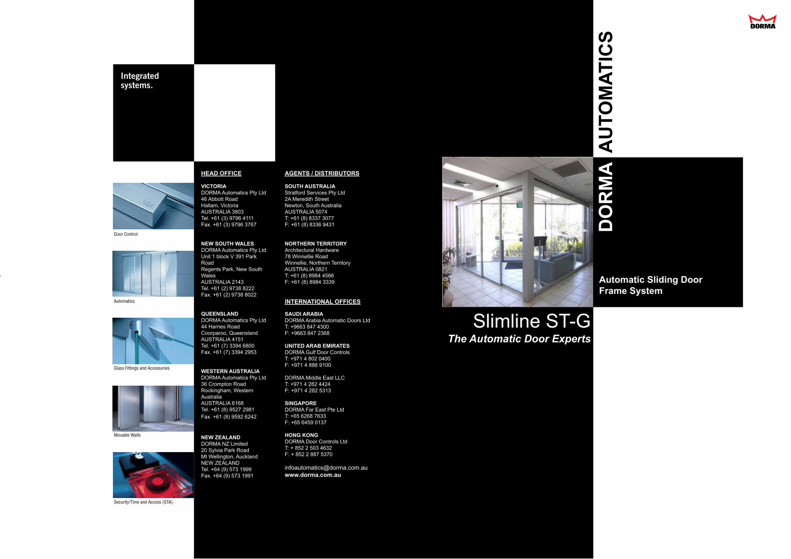
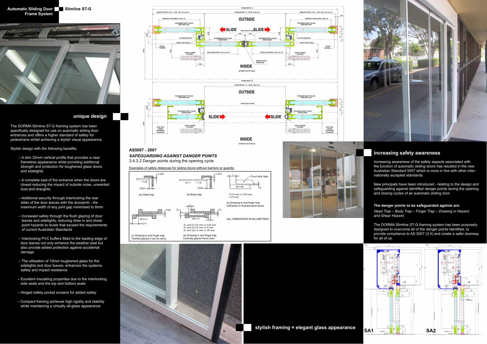
unique design
stylish framing = elegant glass appearance SA2SA1

DORMA GmbH + Co. KGDORMA Platz 158256 ENNEPETALGERMANYPhone +49 2333 793-0Fax +49 2333 793-4950www.dorma.com
Layo
ut S
. 6 –
DO
RM
A CI
-201
2 •
Engl
isch
• S
tand
11.
09.2
012
DORMA_U4-Adressen_CI-2012.indd 6 07.06.13 10:54
FFT FFT-F—
WN
052
010
515
32,
04/1
2, F
FT,
FFT-
F, D
, x.
xx.
xx/
11S
ubje
ct t
o ch
ange
wit
hout
not
ice
Automatic bi-folding doors
1
2
3
4
99
10
7
8
5 5
6
11
2
DORMA FFT, FFT-F
Automatic bi-folding doors
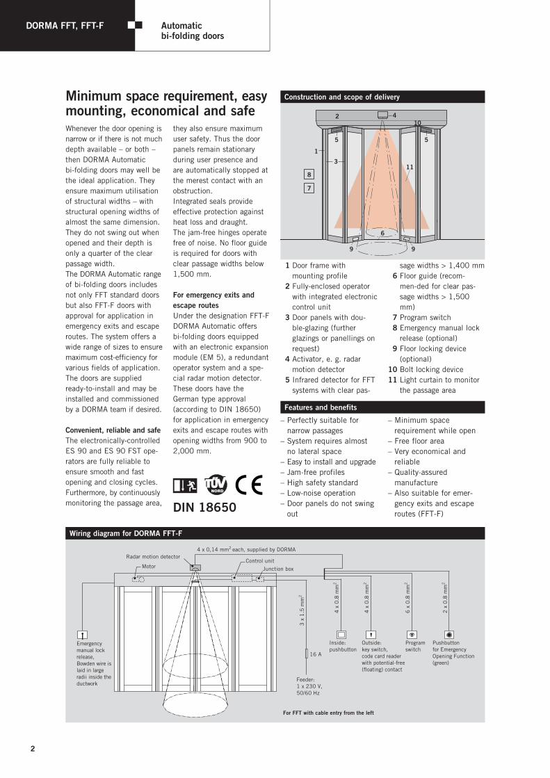
Whenever the door opening is narrow or if there is not much depth available – or both – then DORMA Automatic bi-folding doors may well be the ideal application. They ensure maximum utilisation of structural widths – with structural opening widths of almost the same dimension. They do not swing out when opened and their depth is only a quarter of the clear passage width.The DORMA Automatic range of bi-folding doors includes not only FFT standard doors but also FFT-F doors with approval for application in emergency exits and escape routes. The system offers a wide range of sizes to ensure maximum cost-efficiency for various fields of application. The doors are supplied ready-to-install and may be installed and commissioned by a DORMA team if desired.
Convenient, reliable and safeThe electronically-controlled ES 90 and ES 90 FST ope- rators are fully reliable to ensure smooth and fast opening and closing cycles. Furthermore, by continuously monitoring the passage area,
they also ensure maximum user safety. Thus the door panels remain stationary during user presence and are automatically stopped at the merest contact with an obstruction.Integrated seals provide effective protection against heat loss and draught. The jam-free hinges operate free of noise. No floor guide is required for doors with clear passage widths below 1,500 mm.
For emergency exits and escape routesUnder the designation FFT-F DORMA Automatic offers bi-folding doors equipped with an electronic expansion module (EM 5), a redundant operator system and a spe-cial radar motion detector. These doors have the German type approval (according to DIN 18650) for application in emergency exits and escape routes with opening widths from 900 to 2,000 mm.
Minimum space requirement, easy mounting, economical and safe
11 Door frame with mounting profile
12 Fully-enclosed operator with integrated electronic control unit
13 Door panels with dou-ble-glazing (further glazings or panellings on request)
14 Activator, e. g. radar motion detector
15 Infrared detector for FFT systems with clear pas-
sage widths > 1,400 mm 16 Floor guide (recom-
men-ded for clear pas-sage widths > 1,500 mm)
17 Program switch18 Emergency manual lock
release (optional)19 Floor locking device
(optional)10 Bolt locking device11 Light curtain to monitor
the passage area
Construction and scope of delivery
Features and benefits
3 x
1.5
mm
2
6 x
0.8
mm
2
2 x
0.8
mm
2
4 x
0.8
mm
2
Feeder:1 x 230 V, 50/60 Hz
Inside:pushbutton
Outside:key switch,code card readerwith potential-free(floating) contact
16 A
For FFT with cable entry from the left
Programswitch
Pushbuttonfor EmergencyOpening Function(green)
4 x
0.8
mm
2
4 x 0,14 mm2 each, supplied by DORMA
Control unitMotor Junction box
Radar motion detector
Emergencymanual lockrelease, Bowden wire islaid in largeradii inside theductwork
Wiring diagram for DORMA FFT-F
– Perfectly suitable for narrow passages
– System requires almost no lateral space
– Easy to install and upgrade – Jam-free profiles – High safety standard – Low-noise operation – Door panels do not swing
out
– Minimum space requirement while open
– Free floor area – Very economical and
reliable – Quality-assured
manufacture – Also suitable for emer-
gency exits and escape routes (FFT-F)DIN 18650
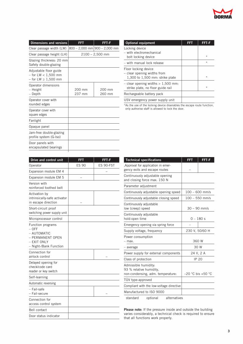
Operator ES 90 ES 90-FST
Expansion module EM 4 � –
Expansion module EM 5 – �
Version with reinforced toothed belt �
Activation by intrinsically-safe activator in escape direction – �
Short-circuit proof switching power supply unit �
Microprocessor control �
Function programs – OFF � – AUTOMATIC � – PERMANENT OPEN � – EXIT ONLY � – Night-/Bank Function �
Connection for airlock control � –
Delayed opening for check/code card reader or key switch �
Self-learning �
Automatic reversing �
– Fail-safe � � – Fail-secure � –
Connection for access control system �
Bell contact �
Door status indicator �
‚Approval for application in emer- gency exits and escape routes – �
Continuously adjustable opening and closing force max. 150 N �
Parameter adjustment �
Continuously adjustable opening speed 100 – 600 mm/s
Continuously adjustable closing speed 100 – 550 mm/s
Continuously adjustable low (creep) speed 30 – 90 mm/s
Continuously adjustable hold-open time 0 – 180 s
Emergency opening via spring force – �
Supply voltage, frequency 230 V, 50/60 H
Power consumption – max. 360 W
– average 30 W
Power supply for external components 24 V, 2 A
Class of protection IP 20
Admissible humidity: 93 % relative humidity, non-condensing, adm. temperature: –20 °C bis +50 °C
TÜV type-approved �
Compliant with the low-voltage directive �
Manufactured to ISO 9000 �
� standard � optional � alternatives
3
Dimensions and versions FFT FFT-F Optional equipment FFT FFT-F
Clear passage width (LW) 800 – 2,000 mm 900 – 2,000 mm
Clear passage height (LH) 2100 – 2,500 mm
Glazing thickness: 20 mm Safety double-glazing �
Adjustable floor guide – for LW < 1,500 mm � – for LW ≥ 1,500 mm �
Operator dimensions – Height 200 mm 200 mm – Depth 237 mm 260 mm
Operator cover with rounded edges �
Operator cover with square edges �
Fanlight �
Opaque panel �
Jam-free double-glazing profile system (G-Iso) �
Door panels with encapsulated bearings �
Locking device – with electromechanical
bolt locking device � �*
– with manual lock release � �*
Floor locking device – clear opening widths from
1,300 to 1,500 mm: strike plate � �*
– clear opening widths > 1,500 mm: strike plate, no floor guide rail � �*
Rechargeable battery pack �
USV emergency power supply unit �* As the use of the locking device disenables the escape route function, only authorise staff is allowed to lock the door.
Drive and control unit FFT FFT-F Technical specifications FFT FFT-F
Please note: If the pressure inside and outside the building varies considerably, a technical check is required to ensure that all functions work properly.
4
DORMA FFT, FFT-F
Automatic bi-folding doors
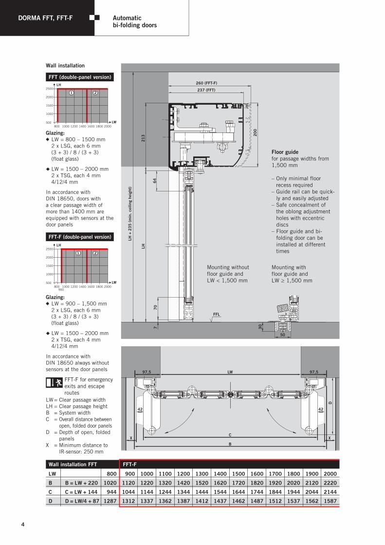
Wall installation FFT FFT-F
LW 1800 1900 1000 1100 1200 1300 1400 1500 1600 1700 1800 1900 2000
B B = LW + 220 1020 1120 1220 1320 1420 1520 1620 1720 1820 1920 2020 2120 2220
C C = LW + 144 1944 1044 1144 1244 1344 1444 1544 1644 1744 1844 1944 2044 2144
D D = LW/4 + 87 1287 1312 1337 1362 1387 1412 1437 1462 1487 1512 1537 1562 1587
260 (FFT-F)
237 (FFT)
200
64
213
LH +
235
(m
in. c
eilin
g he
ight
)
707
LH
FFL
30
50
XX
42 42
LSLS
LW97,5 97,5
C
B
D
FFT (double-panel version)
2500
2000
1500
1000
500800 1000 1200 1400 1600 1800 2000
LH
LW
1 2
Glazing:q LW = 800 – 1500 mm 2 x LSG, each 6 mm (3 + 3) / 8 / (3 + 3) (float glass)
w LW = 1500 – 2000 mm 2 x TSG, each 4 mm 4/12/4 mm
In accordance with DIN 18650, doors with a clear passage width of more than 1400 mm are equipped with sensors at the door panels
FFT-F (double-panel version)
2500
2000
1500
1000
500
900800 1000 1200 1400 1600 1800 2000
LH
LW
1 2
Glazing:q LW = 900 – 1,500 mm 2 x LSG, each 6 mm (3 + 3) / 8 / (3 + 3) (float glass)
w LW = 1500 – 2000 mm 2 x TSG, each 4 mm 4/12/4 mm
In accordance with DIN 18650 always without sensors at the door panels
FFT-F for emergency exits and escape routes
LW = Clear passage widthLH = Clear passage heightB = System widthC = Overall distance between
open, folded door panelsD = Depth of open, folded
panelsX = Minimum distance to
IR-sensor: 250 mm
Wall installation
Floor guidefor passage widths from 1,500 mm
– Only minimal floor recess required– Guide rail can be quick-
ly and easily adjusted– Safe concealment of
the oblong adjustment holes with eccentric discs
– Floor guide and bi- folding door can be
installed at different times
Mounting without floor guide and LW < 1,500 mm
Mounting with floor guide and LW ≥ 1,500 mm

5
Corridor installation FFT FFT-F
LW 1800 1900 1000 1100 1200 1300 1400 1500 1600 1700 1800 1900 2000
B B = LW + 250 1050 1150 1250 1350 1450 1550 1650 1750 1850 1950 2050 2150 2250
C C = LW + 144 1944 1044 1144 1244 1344 1444 1544 1644 1744 1844 1944 2044 2144
D D = LW/4 + 87 1287 1312 1337 1362 1387 1412 1437 1462 1487 1512 1537 1562 1587
260 (FFT-F)
237 (FFT)
200
64
213
70
LH
H
7
FFL
30
50
68
34
42 42
X X
LSLS
D
LW125 125
C
B
66 66
FFT-F for emergency exits and escape routes
LW = Clear passage widthLH = Clear passage heightB = System widthC = Overall distance between
open, folded door panelsD = Depth of open, folded
panelsX = Minimum distance to
IR-sensor: 250 mm
FFT (double-panel version)
2500
2000
1500
1000
500800 1000 1200 1400 1600 1800 2000
LH
LW
1 2
Glazing:q LW = 800 – 1,500 mm 2 x LSG, each 6 mm (3 + 3) / 8 / (3 + 3) (float glass)
w LW = 1500 – 2000 mm 2 x TSG, each 4 mm 4/12/4 mm
In accordance with DIN 18650, doors with a clear passage width of more than 1400 mm are equipped with sensors at the door panels
FFT-F (double-panel version)
2500
2000
1500
1000
500
900800 1000 1200 1400 1600 1800 2000
LH
LW
1 2
Glazing:q LW = 900 – 1,500 mm 2 x LSG, each 6 mm (3 + 3) / 8 / (3 + 3) (float glass)
w LW = 1500 – 2000 mm 2 x TSG, each 4 mm 4/12/4 mm
In accordance with DIN 18650 always without sensors at the door panels
Corridor installation
Floor guidefor passage widths from 1,500 mm
– Only minimal floor recess required
– Guide rail can be quick-ly and easily adjusted
– Safe concealment of the oblong adjustment holes with eccentric discs
– Floor guide and bi-folding door can be installed at different times
Mounting without floor guide for LW < 1,500 mm
Mounting with floor guide for LW ≥ 1,500 mm
6
DORMA FFT, FFT-F
System accessories
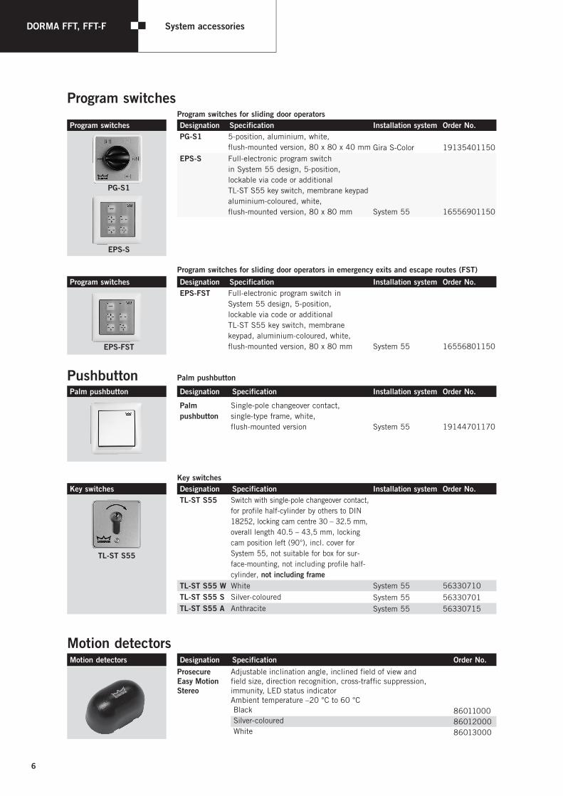
Program switchesProgram switches for sliding door operators
Program switches Designation Specification Installation system Order No.PG-S1 5-position, aluminium, white,
flush-mounted version, 80 x 80 x 40 mm Gira S-Color 19135401150EPS-S Full-electronic program switch
in System 55 design, 5-position, lockable via code or additional TL-ST S55 key switch, membrane keypad aluminium-coloured, white, flush-mounted version, 80 x 80 mm System 55 16556901150
Program switches for sliding door operators in emergency exits and escape routes (FST)Program switches Designation Specification Installation system Order No.
EPS-FST Full-electronic program switch in System 55 design, 5-position, lockable via code or additional TL-ST S55 key switch, membrane keypad, aluminium-coloured, white, flush-mounted version, 80 x 80 mm
System 55
16556801150
Pushbutton Palm pushbutton
Palm pushbutton Designation Specification Installation system Order No.
Palm pushbutton
Single-pole changeover contact, single-type frame, white, flush-mounted version System 55 19144701170
Key switchesKey switches Designation Specification Installation system Order No.
TL-ST S55
TL-ST S55 Switch with single-pole changeover contact, for profile half-cylinder by others to DIN 18252, locking cam centre 30 – 32.5 mm, overall length 40.5 – 43,5 mm, locking cam position left (90°), incl. cover for System 55, not suitable for box for sur-face-mounting, not including profile half-cylinder, not including frame
TL-ST S55 W White System 55 56330710TL-ST S55 S Silver-coloured System 55 56330701TL-ST S55 A Anthracite System 55 56330715
Motion detectorsMotion detectors Designation Specification Order No.
Prosecure Easy Motion Stereo
Adjustable inclination angle, inclined field of view and field size, direction recognition, cross-traffic suppression, immunity, LED status indicatorAmbient temperature –20 °C to 60 °CBlack 86011000Silver-coloured 86012000White 86013000
PG-S1
EPS-S
EPS-FST
7
2032
136
108
40 50
160
25
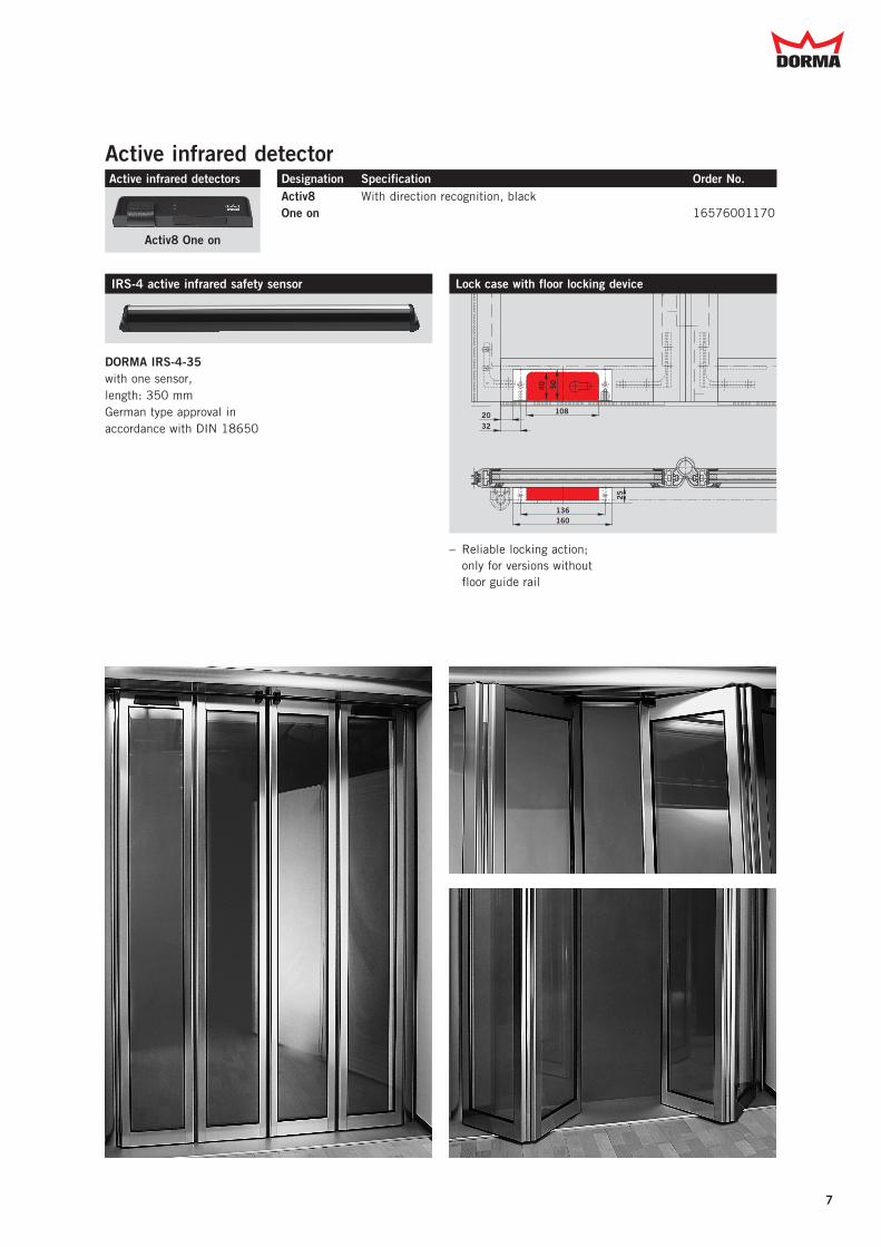
Lock case with floor locking device
– Reliable locking action; only for versions without floor guide rail
DORMA IRS-4-35 with one sensor, length: 350 mmGerman type approval in accordance with DIN 18650
IRS-4 active infrared safety sensor
Active infrared detectorActive infrared detectors Designation Specification Order No.
Activ8 One on
Activ8 One on
With direction recognition, black16576001170

DORMA GmbH + Co. KGDORMA Platz 158256 ENNEPETALGERMANYPhone +49 2333 793-0Fax +49 2333 793-4950www.dorma.com
Layo
ut S
. 6 –
DO
RM
A CI
-201
2 •
Engl
isch
• S
tand
11.
09.2
012
DORMA_U4-Adressen_CI-2012.indd 6 07.06.13 10:54
DORMA Australia Head Office46-52 Abbott Road,Hallam, Victoria 3803Telephone (03) 8795 0270Facsimile (03) 8795 0696Toll Free 1800 675 411
DORMA NZ LimitedHead OfficeBuilding P61-69 Patiki RoadAvondale
c a d e e e ac e
WN
052
010
515
32,
04/1
2, F
FT,
FFT-
F, D
, x.
xx.
xx/
11S
ubje
ct t
o ch
ange
wit
hout
not
ice