Embed Size (px)
Citation preview

Material measures of length for general use.Part 3: Test report format
Mesures matérialisées de longueur pour usages généraux. Partie 3: Format du rapport d'essais
OIM
L R 35-3 Edition 201
1 (E)
OIML R 35-3Edition 2011 (E)
ORGANISATION INTERNATIONALE
DE MÉTROLOGIE LÉGALE
INTERNATIONAL ORGANIZATION
OF LEGAL METROLOGY
INTERNATIONAL
RECOMMENDATION


OIML R 35-3:2011 (E)
3
Contents
Foreword .................................................................................................................................................................. 4
Explanatory notes to the Test Report Format ........................................................................................................... 5
I Type evaluation report ................................................................................................................................. 6
1 Information concerning the type .................................................................................................................. 6 1.1 General ............................................................................................................................................................ 6 1.2 Model submitted ............................................................................................................................................. 6 1.3 Material measures of length (complete) .......................................................................................................... 7 1.4 Separate blade ................................................................................................................................................. 8 1.5 Separate case ................................................................................................................................................... 9 1.6 Separate sinker ................................................................................................................................................ 9 1.7 Supplementary readout/display ..................................................................................................................... 10 1.8 Supplementary electronic sensing device ...................................................................................................... 11 1.9 Identification .................................................................................................................................................. 12
2 Documents concerning the type .................................................................................................................. 12
3 General information concerning the test equipment ............................................................................... 12
4 General information concerning simulators ............................................................................................. 12
5 Checklist for measures of length examinations and performance tests .................................................. 13 5.1 Checklist for external examinations ............................................................................................................... 13 5.2 Checklist for accuracy tests ............................................................................................................................ 28 5.3 Checklist for influence factor and disturbance tests for electronic devices.................................................... 29
6 Type evaluation tests (for all measures of length) .................................................................................... 31 6.1 Datasheet for blade accuracy calculations ..................................................................................................... 31 6.2 Scale accuracy and large scale linearity ......................................................................................................... 32 6.3 Scale interval accuracy................................................................................................................................... 33 6.4 Scale interval linearity ................................................................................................................................... 33 6.5 Accuracy of other metrological components ................................................................................................. 34 6.6 Indicating devices .......................................................................................................................................... 35
7 Tests for influence factors and disturbances ............................................................................................ 37 7.1 Static temperatures (specified high) ............................................................................................................... 37 7.2 Static temperatures (specified low) ................................................................................................................ 38 7.3 Damp heat, cyclic (condensing) ..................................................................................................................... 39 7.4 Mechanical shock ........................................................................................................................................... 40 7.5 Radio-frequency immunity ............................................................................................................................ 41 7.6 Electrostatic discharge ................................................................................................................................... 43 7.7 Voltage of battery power source .................................................................................................................... 44
II Initial verification report ............................................................................................................................. 45
1 Information concerning the EUT verified ...................................................................................................... 45 2 Initial Verification Test Report ...................................................................................................................... 46 2.1 Example 1: Approved measure (no ancillary electronic devices) .................................................................. 46 2.2 Example 2: Approved measure(with ancillary electronic devices) ................................................................ 48
Annex A (Mandatory) – List of documents received from the manufacturer concerning the type ........................ 50
Annex B (Mandatory) – List of test equipment used in examinations and tests ..................................................... 51
Annex C (Mandatory, when applicable) – List of simulators used in examinations and tests ............................... 52

OIML R 35-3:2011 (E)
4
Foreword
The International Organization of Legal Metrology (OIML) is a worldwide, intergovernmental organization whose primary aim is to harmonize the regulations and metrological controls applied by the national metrological services, or related organizations, of its Member States. The main categories of OIML publications are:
International Recommendations (OIML R), which are model regulations that establish the metrological characteristics required of certain measuring instruments and which specify methods and equipment for checking their conformity. OIML Member States shall implement these Recommendations to the greatest possible extent;
International Documents (OIML D), which are informative in nature and which are intended to harmonize and improve work in the field of legal metrology;
International Guides (OIML G), which are also informative in nature and which are intended to give guidelines for the application of certain requirements to legal metrology; and
International Basic Publications (OIML B), which define the operating rules of the various OIML structures and systems.
OIML Draft Recommendations, Documents and Guides are developed by Project Groups linked to Technical Committees or Subcommittees which comprise representatives from OIML Member States. Certain international and regional institutions also participate on a consultation basis. Cooperative agreements have been established between the OIML and certain institutions, such as ISO and the IEC, with the objective of avoiding contradictory requirements. Consequently, manufacturers and users of measuring instruments, test laboratories, etc. may simultaneously apply OIML publications and those of other institutions.
International Recommendations, Documents, Guides and Basic Publications are published in English (E) and translated into French (F) and are subject to periodic revision.
Additionally, the OIML publishes or participates in the publication of Vocabularies (OIML V) and periodically commissions legal metrology experts to write Expert Reports (OIML E). Expert Reports are intended to provide information and advice, and are written solely from the viewpoint of their author, without the involvement of a Technical Committee or Subcommittee, nor that of the CIML. Thus, they do not necessarily represent the views of the OIML.
This publication - reference OIML R 35-3, edition 2011 (E) - was developed by the OIML Technical Subcommittee TC 7 Measuring instruments for length and associated quantities. It was approved for final publication by the International Committee of Legal Metrology in 2011.
OIML Publications may be downloaded from the OIML web site in the form of PDF files. Additional information on OIML Publications may be obtained from the Organization’s headquarters:
Bureau International de Métrologie Légale 11, rue Turgot - 75009 Paris - France Telephone: 33 (0)1 48 78 12 82 Fax: 33 (0)1 42 82 17 27 E-mail: [email protected] Internet: www.oiml.org

OIML R 35-3:2011 (E)
5
Material measures of length for general use Part 3: Test Report Format
Explanatory notes to the Test Report Format Implementation of this Test Report Format is informative with regard to the implementation of R 35-1 and R 35-2 in national regulations; however, its implementation is mandatory within the framework of the OIML Basic Certificate System for OIML Type Evaluation of Measuring Instruments [R 35-2, 9]. Section I shows the required format of a type evaluation report for a measure of length. A type evaluation report for a dimensioned case or electronic sensing device requires a similar format. However, some modifications to the tables may be required because a large number of variations in the design of these separable units is possible. Some examples of tables for presenting the test results for measures and ancillary devices are shown in Section II for initial verification reports. These tables may also be adapted for type evaluation reports. Meaning of symbols: / .................... Indication EUT ............. Equipment Under Test mpe .............. Maximum permissible error For each examination and test the checklist shall be completed according to this example: For each test, the “SUMMARY OF TYPE EVALUATION” and the “CHECKLIST” shall be completed according to this example:
P F P = Passed
F = Failed
when the instrument has passed the test: X when the instrument has failed the test: X when the test is not applicable: / /
The white spaces in boxes in the headings of the report should always be filled according to the following example:
At start At end Temp.: 20.5 21.1 °C Rel. h.: %
Date: 2012-04-20 2012-04-21 yyyy-mm-dd Time: 16:00:05 16:30:25 hh:mm:ss
where: Temp. = temperature Rel.h. = relative humidity "Date" in the test reports refers to the date on which the test was performed.

OIML R 35-3:2011 (E)
6
I Type Evaluation Report
1 Information concerning the type
1.1 General Application number: ................................................................................................................................
Applicant: ................................................................................................................................
Authorized representative: ................................................................................................................................
Address: ................................................................................................................................
................................................................................................................................
................................................................................................................................
................................................................................................................................
Testing laboratory: ................................................................................................................................
Address: ................................................................................................................................
................................................................................................................................
................................................................................................................................
................................................................................................................................
1.2 Model submitted New model: ...................................................................................................................................................
.........................................................................................................................................................................................
.........................................................................................................................................................................................
Variant of approved model (details): ..............................................................................................................................
.........................................................................................................................................................................................
.........................................................................................................................................................................................
Approval number: .............................................................................................................................................

OIML R 35-3:2011 (E)
7
Table 1 Model submitted
Submitted for approval tests Yes* No* Remarks
Material measure of length (complete)
Separate blade
Separate case
Separate sinker
Supplementary readout/display
(permanently attached to measure)
Supplementary electronic sensing device
(permanently attached to measure)
* Tick (X) as appropriate
1.3 Material measure of length (complete) Manufacturer: ...............................................................................................................................................
Model number: ...............................................................................................................................................
Type details:
Category (R 35-2, 7.1.a): ...........................................................................................................................
Sub-category (R 35-2, 7.1.b): .....................................................................................................................
Blade material: ...........................................................................................................................................
Accuracy class (R 35-1, 4.1): ...........................
Nominal length: ........................ m
Blade width: ..................... mm
Scale interval: ..................... mm
If applicable:
Maximum admissible temperature: ................... °C
Environmental class (R 35-1, 27.4): .............................................................
Mechanical environment (R 35-2, 8.3): ........................................................
Electromagnetic environment (R 35-2, 8.4): .................................................

OIML R 35-3:2011 (E)
8
Installation details:
Tension: .................................... N
Other relevant information:
Coefficient of thermal expansion: ............................ 10-6 per °C
Internal impedance of specified power source: ........................... ohm
Additional: ..........................................................................................................................................
1.4 Separate blade Manufacturer: ...............................................................................................................................................
Model number: ...............................................................................................................................................
Type details:
Category (R 35-2, 7.1.a): ....................................................................................................................
Sub-category (R 35-2, 7.1.b): ..............................................................................................................
Blade material: ....................................................................................................................................
Accuracy class (R 35-1, 4.1): .....................
Nominal length: ....................... m
Blade width: .................... mm
Scale interval: .................... mm
Installation details:
Tension: .................................... N
Other relevant information:
Coefficient of thermal expansion: .......................... 10-6 per °C
Additional: ..........................................................................................................................................
Approval nos. of compatible blades: .....................................................................................................

OIML R 35-3:2011 (E)
9
1.5 Separate case Manufacturer: ...............................................................................................................................................
Model number: ...............................................................................................................................................
Type details:
Category (R 35-2, 7.1.a): ....................................................................................................................
Accuracy class (R 35-1, 4.1): ......................................
Blade nominal length: .................................. m
Blade width: ................................. mm
Case dimensions: ................................ mm
Installation details: ..................................................................................................................................
Approval nos. of compatible blades: .....................................................................................................
1.6 Separate sinker Manufacturer: ...............................................................................................................................................
Model number: ...............................................................................................................................................
Type details:
Category (R 35-2, 7.1.a): ....................................................................................................................
Sinker material: ...................................................................................................................................
Accuracy class (R 35-1, 4.1): ......................................
Blade nominal length: .................................. m
Blade width: ................................. mm
Sinker length: ................................ mm
Sinker mass: .................................... g
Thermal coefficient of linear expansion: ............................... 10-6 per °C
Installation details: ..................................................................................................................................
Approval nos. of compatible blades: .....................................................................................................

OIML R 35-3:2011 (E)
10
1.7 Supplementary readout/display
Manufacturer: ...............................................................................................................................................
Model number: ...............................................................................................................................................
Type details of compatible blades:
Category (R 35-2, 7.1.a): ....................................................................................................................
Accuracy class (R 35-1, 4.1): .....................
Nominal length: ....................... m
Scale interval: .................... mm
Approval nos. of compatible blades: .....................................................................................................
Power source:
Type (battery, solar, etc.): .................................................................................................................
Umax: ........................................ V
Umin: ........................................ V
Internal impedance: .......................... ohm
Frequency (if applicable): ................... Hz
Installation details (electrical):
Wiring instructions: ...........................................................................................................................
Mounting arrangement: ......................................................................................................................
Orientation limitations: .......................................................................................................................
Maximum admissible temperature: .................. °C
Environmental class (R 35-1, 27.4): ........................................
Mechanical environment (R 35-2, 8.3): ........................................
Electromagnetic environment (R 35-2, 8.4): ........................................

OIML R 35-3:2011 (E)
11
1.8 Supplementary electronic sensing device
Manufacturer: ...............................................................................................................................................
Model number: ...............................................................................................................................................
Type details of compatible blades:
Category (R 35-2, 7.1.a): ....................................................................................................................
Sub-category (R 35-2, 7.1.b): ...............................................................................................................
Accuracy class (R 35-1, 4.1): .....................
Nominal length: ....................... m
Blade width: .................... mm
Scale interval: .................... mm
Approval nos. of compatible blades: .....................................................................................................
Power source:
Type (battery, solar, etc.): .................................................................................................................
Umax: ........................................ V
Umin: ........................................ V
Internal impedance: .......................... ohm
Frequency (if applicable): ................... Hz
Installation details (electrical):
Wiring instructions: ...........................................................................................................................
Mounting arrangement: ......................................................................................................................
Orientation limitations: .......................................................................................................................
Maximum admissible temperature: .................. °C
Environmental class (R 35-1, 27.4): ........................................
Mechanical environment (R 35-2, 8.3): ........................................
Electromagnetic environment (R 35-2, 8.4): ........................................

OIML R 35-3:2011 (E)
12
1.9 Identification Add any additional information pertaining to identification of the EUT: (attach photograph here, if available)
2 Documents concerning the type (R 35-2, 5) Annex A provides a table on which the documents submitted by the manufacturer with the type for testing shall be listed.
3 General information concerning the test equipment Details of all items of measuring equipment and test instruments used for the type examinations and initial verifications shall be listed in Annex B, e.g. instruments for measuring:
• linear dimensions, • temperature, • voltage • signal generators (for pulse, current or voltage).
4 General information concerning simulators Details of any simulators used for the type examinations and initial verifications shall be listed in Annex C.

OIML R 35-3:2011 (E)
13
5 Checklist for measures of length examinations and performance tests
5.1 Checklist for external examinations Note: § (R 35-1) Refers to clause numbers in OIML R 35-1 Material measures of length. Part 1:Metrological and technical requirement Edition 2007 (E).
5.1.1 External examination for all measures of length
§ (R 35-1)
Requirement P F Remarks
5 Nominal length
5.1 The nominal length in column 1 shall be an integral multiple of the factor shown in column 2.
Nominal length m
Multiple of m
≤15 0.5 15 < L ≤ 100 5
>100 50
5.2 Other values may be deemed appropriate for specific applications provided that the specific application is clearly indicated on the measure.
5.3
Land surveying measures shall have nominal lengths of 5 m, 10 m, 20 m, 50 m, 100 m or 200 m.
6 Materials 6.1 The measures and their supplementary
devices shall be made of materials which, under normal conditions of use, are sufficiently durable, stable and resistant to environmental influences.
6.2 The variations in length due to temperature differences equal to 8 °C above or below the reference temperature shall not exceed the maximum permissible errors for the accuracy class to which the measure belongs;
A variation of ±10 % of the specified tension shall not produce a variation in length exceeding the maximum permissible error.
OIML R 35-3:2011 (E)
14
§ (R 35-1)
Requirement P F Remarks
7 Construction 7.1 The measures and their supplementary
devices shall be well and robustly constructed and carefully finished.
7.2 The dimensions and shape of the cross-section of measures shall be such that, under normal conditions of use, measurements can be made with the degree of accuracy required for the accuracy class to which the measures belong.
7.3 Tape measure: when it is stretched out on a flat surface, the tape measure’s edges shall be virtually straight and parallel.
7.4 End measure: the surfaces forming the two principal scale marks (end surfaces) shall be flat and perpendicular to the longitudinal axis of the measure.
7.5 End or composite measure made of wood or other material of durability equal to or less than that of wood: the end surfaces shall be provided with a bracket, plate or end fitting, which is resistant to wear and impact damage and is suitably attached to the measure.
7.6 Supplementary devices shall not cause confusion and shall be designed and attached to the measure in such a way that, under normal conditions of use, it is virtually impossible for the measurement uncertainty to be increased.
7.7 Tape measure: winding devices shall be made in such a way that they do not cause any permanent deformation of the tape.
7.8 On certain types of measures, a blank length of the measure, extending beyond the principal scale mark at the end of the measure and long enough for verification purposes, may be provided.
8 Scale 8.1 The scale shall be clear, regular,
indelible and carried out in such a way that reading is definite, easy and unambiguous.

OIML R 35-3:2011 (E)
15
§ (R 35-1)
Requirement P F Remarks
8.2 The scale interval shall be of the form:
1 × 10n, 2 × 10n or 5 × 10n m,
Where n is a positive or negative whole number or zero.
For the nominal lengths shown in column 1, the scale interval shall not exceed the values shown in column 2.
Nominal length m
Maximum interval size
0.5, 1.0 1 mm 1.0 < L ≤ 2 1 cm
2.0 < L < 10 10 cm 10.0 ≤ L < 50 20 cm
>50 50 cm Note: These values may be exceeded for specific applications, provided that the specific application is indicated on the measure.
8.3 When the scale marks are lines: a) They shall be straight,
perpendicular to the axis of the measure, and all shall have the same width, which shall be constant throughout their length
b) The length of the lines shall be related to the corresponding unit of measurement. The lines shall be such that they form a distinct and clear scale and that their width shall not cause any measurement uncertainty.
c) The maximum admissible width of the lines shall not exceed the values given in Table 1 of R 35-2.
8.4 Certain sections of the scale, particularly towards the ends, may be subdivided into decimal sub-multiples of the scale interval adopted for the measure as a whole.
The width of the lines may be less in the areas of reduced scale intervals than on the rest of the measure.

OIML R 35-3:2011 (E)
16
§ (R 35-1)
Requirement P F Remarks
8.5 Scale marks may also take other forms:
Scale interval Optional form of scale mark*
≥ 1 cm Holes ≥ 1 dm Other marks
* Provided that these marks ensure sufficiently precise reading, taking into account the accuracy class to which the measure belongs.
8.6 A measure may have more than one scale, for which the scale intervals may be different.
9 Numbering 9.1 The numbering shall be clear, regular,
indelible, and carried out in such a way that reading is definite, easy, and unambiguous.
9.2 The numbering sequence shall be fully sequential, or partially sequential and partially repetitive.
In the case covered by 8.4 above, the numbering in parts with reduced scale intervals may be different from that for the rest of the measure.
9.3 The position, dimensions, shape, colour and contrast of the numbers shall be appropriate to the scale and the associated scale marks.
Depending on how the measure is to be read, the numbers shall be inscribed parallel or perpendicular to the edge of the measure.
9.4
The numbers representing millimetres, centimetres, decimetres, or metres shall not be accompanied by the corresponding symbols
Only scale marks corresponding to complete metres may be numbered in metres, in which case these numbers shall be followed by the symbol “m”. The number of preceding metres may be repeated in the same way in front of the other numbered scale marks.
Millimetre scales shall be numbered every centimetre.
Line measures whose scale interval is in the form of 2 × 10n and is not less than 2 cm: all scale marks shall be numbered.

OIML R 35-3:2011 (E)
17
§ (R 35-1)
Requirement P F Remarks
9.5 On a measure with several scales, the numbering of these scales may be different and the numbering systems may increase in the same direction or in the opposite direction.
10 Inscriptions 10.1 The following inscriptions are
mandatory in all cases:
a) Nominal length (optional in a rectangle) (see 10.3 below);
b) Numeric code, trade mark or trade name of the manufacturer and/or of his representative;
c) Designation of accuracy class: I, II, or III in an oval.
10.2 The following inscriptions are mandatory in certain cases:
a) Reference temperature, if other than 20 °C (see 10.3 below);
b) Tension, if specified (see 10.3 below);
c) Specific use for which the measure is intended, in the cases covered by R 35-1, 5 (nominal length) and R 35-1, 8.2 (scale interval).
10.3 Nominal length, temperature, and tension shall be expressed in one of the units specified in the OIML International Document D 2 Legal units of measurement, followed by the corresponding legal symbol.
10.4 All of these inscriptions shall be clearly visible and readable, and placed at the beginning of the measure or on the case of the measure if the case and measure are not separable.
10.5 Other non-metrological inscriptions specified in particular regulations or authorized by competent national authorities may appear on the measure.
10.6 Advertising inscriptions may appear on the measures, provided that the requirement of 10.7 is met.
10.7 All inscriptions shall be arranged so that they do not interfere with the reading of the measure.

OIML R 35-3:2011 (E)
18
§ (R 35-1)
Requirement P F Remarks
10. 8 Under the sole responsibility of the manufacturer, the thermal expansion coefficient of the material of which the measure is made, may be indicated in the form α = .../°C or α = ... K-1.
11 Indicating device 11.1.1 Indicating devices may be used only
with semi-rigid steel tape measures with readout and with flexible steel tape measures with tensioning weight or sinker equipped with electronic sensing.
11.1.2 The indicating device shall be in addition to the scale marks on the blade.
The indicating device shall provide an easily read, reliable and unambiguous visual indication of the indicated length throughout the whole length of the measure.
11.1.3 The indicating device shall display the indicated length up to and including the nominal length of the measure.
11.1.4 The indicated length shall be expressed in metres (symbol m) or authorized multiples and sub-multiples and the appropriate symbol shall appear immediately adjacent to the indicated length.
11.1.5
The indicated length is given by a line of adjacent digits appearing in one or more apertures.
The advance of a given digit shall be completed while the digit of the next immediately lower decade changes from 9 to 0.
11.1.6 The length displayed on the indicating device shall agree with the measurement made by the blade to the nearest scale interval of the blade.
11.1.7 There shall be no ambiguity in distinguishing between the length currently being measured and alternative displays.

OIML R 35-3:2011 (E)
19
§ (R 35-1)
Requirement P F Remarks
11.2.2 On switch-on and optionally on demand, it shall be possible to visually check the correct operation of the entire display. This shall comprise:
• displaying all the elements (“eights” test);
• blanking all the elements (“blank” test);
• displaying “zeros” (“zeros” test).
Each step of the sequence shall last at least 0.5 s.
13 Verification (or control) marks Measures shall be constructed so that
they can accommodate the verification (or control) marks prescribed by national regulations; a space shall be provided for this purpose near the beginning of the measure.
A — MEASURES FOR SHORT LENGTHS
14 Semi-rigid steel tape measures in a case 14.1
These measures shall have nominal lengths between 0.5 m and 15 m. See also 5.1 & 5.2.
They shall be of the end, line, or composite type.
14.2.1 If the zero end is of a squared end type and is fitted with a ring, this ring may be included in the nominal length of the measure.
14.2.2 The means of fastening a supplementary device to the end of a measure shall be permitted to obscure the scale marks at the beginning of the measure only under the following conditions:
Nominal length m
Length of scale marking that may be obscured
< 5 None 5 ≤ L ≤ 10 ≤ first 15 mm
> 10 ≤ first 30 mm
14.2.3 For measures contained in a case that is designed to be part of the range of the scale:
- the zero end of the blade shall be of the end type;
- the blade shall be provided with a fixed or sliding hook or tongue;

OIML R 35-3:2011 (E)
20
§ (R 35-1)
Requirement P F Remarks
- the case is correctly marked with its dimensions including the measuring unit symbol.
14.2.4
- a belt clip or carrying strap, if fitted, must not obscure the case dimensions marked on the side of the case;
- a belt clip or carrying strap, if fitted to a dimensioned case, must not interfere with internal measurements (i.e. must not prevent the end of the case touching the object being measured).
14.2.5 The blade lock, if fitted, shall be strong enough to hold the blade at all extensions up to and including fully extended.
14.2.6 The cross-section of the blade shall be cambered (i.e. the blade shall be of curved cross-section).
14.3.1 These measures may have two scales with the same point of origin on the same face;
They may also have a scale on the other face.
14.3.2 The scale interval shall be less than or equal to 1 cm.
14.4 These measures shall conform to accuracy class I or II.
15 Semi-rigid steel tape measures in a case with digital readout 15.1 These measures have nominal lengths
between 0.5 m and 15 m. See also 5.1 & 5.2.
They shall be of the end, line, or composite type.
15.2.1 If the zero end is of a squared end type and is fitted with a ring, this ring may be included in the nominal length of the measure.
15.2.2 For measures contained in a case that is designed to be part of the range of the scale:
- the dimension of the case shall be indicated on the case.
- the zero end of the blade shall be of the end type.
- the blade shall be provided with a fixed or sliding hook or tongue.

OIML R 35-3:2011 (E)
21
§ (R 35-1)
Requirement P F Remarks
15.2.3 The blade lock, if fitted, shall be strong enough to hold the blade at all extensions up to and including fully extended.
15.2.4 The cross-section of the blade shall be cambered (i.e. the blade shall be of curved cross-section).
15.3.1 These measures may have two scales with the same point of origin on the same face
They may also have a scale on the other face.
15.3.2 The scale interval shall be less than or equal to 1 cm.
15.4.1 The power source compartment shall form an integral part of the measure
15.5 These measures shall conform to accuracy class I or II.
16 One-piece rigid or semi-rigid measures 16.1 These measures shall have nominal
lengths between 0.5 m and 5 m. See also 5.1 & 5.2.
They shall be of the end, line, or composite type.
16.2.1 These measures shall be made of metal or other suitable materials.
16.2.2 If the zero scale mark of a dipstick is its end, this end shall be provided with an impact and wear resistant heel or tip made of a material not liable to cause sparking on impact.
16.3 These measures may have a scale on each of the two faces.
16.4 These measures shall conform to accuracy class I or II.
17 Flexible tape measures made of fibreglass and plastic or other suitable non-metallic materials
17.1 These measures shall have nominal lengths between 0.5 m and 5 m. See also 5.1 & 5.2.
They shall be of the end, line, or composite type.
17.2.1 The free ends of end or composite measures shall be provided with wear-resistant bands or tips which are firmly attached to the tape.
17.2.2 End measure: one end may be fitted with a ring, which may be included in the nominal length of the measure.

OIML R 35-3:2011 (E)
22
§ (R 35-1)
Requirement P F Remarks
17.2.3 The specified tension shall be approximately 10 N to 20 N, and shall be indicated on the measure.
17.2.4 Line measures not fitted with a ring: the zero scale mark shall be located at a distance of at least 20 mm from the nearest end of the measure.
Line measure fitted with a ring: the zero scale mark shall be located at a distance of at least 20 mm from the outer edge of the ring.
17.3 These measures shall conform to accuracy class I, II or III.
18 Folding measures made of metal or other materials 18.1 These measures shall have nominal
lengths between 0.5 m and 5 m. See also 5.1 & 5.2.
They shall be of the end type. 18.2.1 All parts which are jointed at both ends
shall have the same length between their jointing axes.
18.2.2 Jointing and alignment of the unfolded measure shall be ensured by an effective device.
The total additional error due to the jointing and alignment shall not exceed: ± 0.3 mm for measures of class II, ± 0.5 mm for measures of class III.
18.3 These measures may have a scale on each of the two faces.
18.4 These measures shall conform to accuracy class II or III.
Accuracy class I is also permissible for screw-assembly type jointed measures.
19 Telescopic measures made of metal or other materials 19.1 These measures shall have nominal
lengths between 0.5 m and 5 m. See also 5.1 & 5.2.
They shall be of the end type. 19.2.1 Jointing and alignment of the unfolded
measure shall be ensured by an effective device.
19.2.2 These measures shall be made of metal or other suitable materials.
The total additional error due to the jointing and alignment shall not exceed: ± 0.3 mm for measures of class II, ± 0.5 mm for measures of class III.

OIML R 35-3:2011 (E)
23
§ (R 35-1)
Requirement P F Remarks
19.2.3 The terminal surface of the measure shall be flat and perpendicular to the longitudinal axis of the measure.
19.2.4 The end of the measure shall be provided with an impact and wear resistant heel or tip made of a material not liable to cause sparking on impact.
19.3.1 Measures which are circular in cross-section shall have only one scale along their length.
19.3.2 Measures which are rectangular in cross-section may have a scale on each of the two faces.
19.4 These measures shall conform to accuracy class II or III.
20 Telescopic measures made of metal or other materials with digital readout 20.1 – 20.4
Same as 19.1 – 19.4.
20.5.1 If the digital readout is powered, the power source compartment shall form an integral part of the measure.
B — MEASURES FOR LONG LENGTHS
21 Flexible steel tape measures with winding device not designed for measuring lengths greater than their nominal length by repeated use of the same tape
21.1 These measures have nominal lengths between 5 m and 200 m. See also 5.1 & 5.2.
They shall be of the line or composite type.
21.2.1 Class I: the free end shall be provided with a handle or ring, which is not included in the nominal length.
Class II: the free end shall be provided with a handle or ring which may be included in the nominal length.
21.2.2 The means of fastening a supplementary device to the end of a measure shall be permitted to obscure the scale marks at the beginning of the measure only under the following conditions:
Nominal length m
Length of scale marking that may be obscured
5 ≤ L ≤ 10 ≤ first 15 mm >10 ≤ first 30 mm
OIML R 35-3:2011 (E)
24
§ (R 35-1)
Requirement P F Remarks
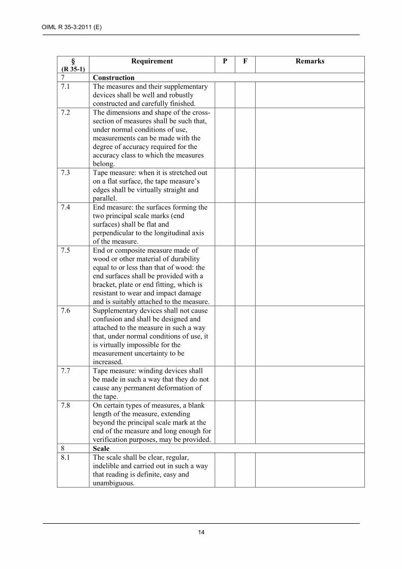
21.2.3 A belt clip or carrying strap, if fitted, must not obscure the dimensions marked on the side of the case.
A belt clip or carrying strap, if fitted, must not interfere with internal measurements (i.e. must not prevent the end of the case touching the object being measured).
21.2.4 The specified tension shall be approximately 50 N or greater, and shall be indicated on the measure.
21.3.1 These measures may have a scale on each of the two faces.
21.3.2 The reference temperature, if other than 20 °C, shall be indicated on the measure (see 10.2).
21.4 These measures shall conform to accuracy class I or II.
22 Flexible steel tape measures with tensioning weight or sinker 22.1 These measures have nominal lengths
between 5 m and 50 m. See also 5.1 & 5.2.
They shall be of the composite type. 22.2 The mass of the sinker shall be
indicated to within ± 10 g, on both measure and sinker.
22.3.1 The sinker shall have a sufficient mass to stretch out the tape properly.
The sinker shall be made of a material not liable to cause sparking on impact.
22.3.2 The sinker may be detachable or permanently attached to the tape.
22.3.3 This attachment or joint shall be such that additional measurement uncertainty is minimised.
22.3.4 The other end of the measure may be provided with a winding device.
22.4 The scale shall be regular, with a scale interval of 1 mm.
The base of the sinker shall constitute the principal scale mark at the zero end of the scale.
The scale shall start on a flat face of the sinker and continue along the entire length of the tape.
22.5 These measures shall conform to accuracy class I or II.

OIML R 35-3:2011 (E)
25
§ (R 35-1)
Requirement P F Remarks
23 Flexible steel tape measures with tensioning weight or sinker equipped with electronic sensing
23.1 These measures have nominal lengths between 5 m and 50 m. See also 5.1 & 5.2.
They shall be of the composite type. 23.2 The mass of the sinker shall be
indicated to within ± 10 g, on both measure and sinker.
23.3.1 The sinker shall have a sufficient mass to stretch out the tape properly.
The sinker shall be made of a material not liable to cause sparking on impact.
23.3.2 The sinker shall be permanently attached to the tape.
This attachment or joint shall not introduce any uncertainty of measurement.
23.3.3 The other end of the measure may be provided with a winding device.
23.4 The scale shall be regular, with a scale interval of 1 mm.
The base of the sinker shall constitute the principal scale mark at the zero end of the scale.
The scale continues along the entire length of the tape.
23.5 The sensing element of the measure shall provide a clear and reliable indication of the air/oil and oil/water phase transition.
23.6.1 If the measure is powered by a replaceable or rechargeable battery, the battery compartment shall form an integral part of the measure.
23.7 These measures shall conform to accuracy class I or II.
With the electronic sensor fitted, the instrument shall conform to the accuracy classes and maximum permissible errors specified in OIML R 85, 3.4.
24 Flexible steel surveyor's tapes designed for measuring lengths greater than their nominal length by repeated use of the same tape
24.1 These measures shall have nominal lengths of 5 m, 10 m, 20 m, 50 m, 100 m, or 200 m.
They shall be of the end or line type. 24.2 The specified tension shall be
approximately 50 N or greater, and shall be indicated on the measure.

OIML R 35-3:2011 (E)
26
§ (R 35-1)
Requirement P F Remarks
24.3 These measures shall be provided with handles or rings at both ends.
If the handles are included in the nominal length of the measure, they shall be so constructed that their attachment to the tape introduces no uncertainty of measurement.
24.4 These measures shall conform to accuracy class I or II.
25 Flexible tape measures made of fibreglass and plastics or other suitable non-metallic materials
25.1 These measures shall have nominal lengths between 5 m and 100 m. See also 5.1 & 5.2.
They shall be of the end, line, or composite type.
25.2.1 End measures: the ends shall be provided with wear-resistant bands or tips which are firmly attached to the tape.
Composite measures: the zero end shall be provided with a wear-resistant band or tip which is firmly attached to the tape.
25.2.2 Class I measures: the free end may be provided with a ring, which is not included in the nominal length.
Measures in class II and III: the free end may be provided with a ring which may be included in the nominal length. In this case, the beginning of the scale shall be clearly indicated.
25.2.3 The means of fastening a supplementary device to the end of a measure shall be permitted to obscure the scale marks at the beginning of the measure only under the following conditions:
Nominal length m
Length of scale marking that may be obscured
5 ≤ L ≤ 10 ≤ first 15 mm > 10 ≤ first 30 mm
25.2.4 A belt clip or carrying strap, if fitted, must not obscure the dimensions marked on the side of the case.
25.2.5 The specified tension shall be approximately 10 N to 20 N and shall be indicated on the measure.

OIML R 35-3:2011 (E)
27
§ (R 35-1)
Requirement P F Remarks
25.3 These measures may have a scale on each of the two faces.
25.4 These measures shall conform to accuracy class I, II or III.

OIML R 35-3:2011 (E)
28
5.2 Checklist for accuracy tests
5.2.1 Accuracy tests for all measures
§ (R 35-1)
Requirement P F Remarks
26.2.2 Scale accuracy and large scale linearity a) The error in the nominal length of
the measure shall not exceed the mpe given in R 35-1, 4.2.1.
b) The error in the distance between two non-consecutive marks at four randomly-chosen points along the length of the measure plus the nominal length shall not exceed the mpe given in R 35-1, 4.2.1.
26.2.3 Scale interval accuracy The error in the length of the scale
interval at four randomly-chosen points along the length of the measure and at the nominal length shall not exceed the mpe given in R 35-1, 4.2.2.
26.2.4 Scale interval linearity The error in the difference between the
lengths of two consecutive scale intervals at four randomly-chosen points along the length of the measure and at the nominal length shall not exceed the mpe given in R 35-1, 4.2.3.
26.2.5 Accuracy of other metrological components The presence of the additional
component shall not cause the error in the length of the blade to exceed the mpe given in 4.2.1 or the error in the length of the component, as a separate entity, shall not exceed the mpe.
27.2 Accuracy tests for indicating devices
27.2.2 Throughout the length of the blade, including zero, the length indicated on the display shall meet the requirement in R 35-1, 11.1.6.
27.2.3 For changes in blade extension of one scale interval, the length indicated on the display shall meet the requirement in R 35-1, 11.1.6.

OIML R 35-3:2011 (E)
29
5.3 Checklist for influence factor and disturbance tests for electronic devices fitted to material measures of length
5.3.1 Performance tests for electronic devices fitted to material measures of length
§ (R 35-1)
Requirement P F Remarks
27.5.1
Static temperatures (dry heat, cold)
During the application of the high and low temperatures:
a) All functions shall operate as designed.
b) There shall be no error in the indication of length during the application of the influence factor (see R 35-1, 11.1.6).
27.5.2 Damp heat, cyclic, condensing After the application of the damp heat
cycles and a recovery period: a) All functions shall operate as
designed. b) There shall be no error in the
indication of length (see R 35-1, 11.1.6).
27.5.2 Mechanical shock (drop test) Following this test there shall be no error
in the indication of length (see R 35-1, 11.1.6).
27.5.4 Immunity against radiated, radio-frequency 27.5.4.1 Electromagnetic fields of general origin The length indicated on the display
shall agree with the measurement made by the blade to the nearest scale interval of the blade (see R 35-1, 11.1.6) whilst the EUT is subjected to the electromagnetic radiation, at the same reference conditions.
27.5.4.2 Electromagnetic fields specifically caused by digital radio telephones The length indicated on the display
shall agree with the measurement made by the blade to the nearest scale interval of the blade (see R 35-1, 11.1.6) whilst the EUT is subjected to the electromagnetic radiation, at the same reference conditions.
27.5.5 Electrostatic discharge There shall be no error in the indication
of length during the application of the influence factor (see R 35-1, 11.1.6)

OIML R 35-3:2011 (E)
30
§ (R 35-1)
Requirement P F Remarks
26.3.5 Voltage of battery power source During the application of the voltage
limits: a) All functions shall operate as
designed. b) There shall be no error in the
indication of length during the application of the influence factor (see R 35-1, 11.1.6).

OIML R 35-3:2011 (E)
31
6 Type evaluation tests (for all measures of length including those with ancillary electronic devices)
At start At end Application no.: Temp.: °C Model: Rel. h.: % Observer: Date: yyyy-mm-dd Time: hh:mm:ss
6.1 Datasheet for blade accuracy calculations The datasheet shown below assumes that all measurements are made from the origin of the measure according to Figure 1 in R 35-2. The origin will be formed by a hook, ring, sinker, or similar in some cases.
Position1 Reading on EUT blade Reading on test
equipment /
a b (m) (m)
A1 A2 A3 B1 B2 B3 C1 C2 C3 D1 D2 D3 E1 E2 E3
Nominal length
Tension: N Coefficient of thermal expansion
10-6 per °C
1 See R 35-2, Figure 1

OIML R 35-3:2011 (E)
32
6.2 Scale accuracy and large scale linearity (R 35-2, 7.4)
Error of EUT blade2
Allowance for ends or jointing 3
Correction due to
thermal expansion
4
Total error
5
mpe 6
P F
α β γ ε = |α| – β + γ (mm) (mm) (mm) (mm) (mm)
aA1 – bA1 aB1 – bB1 aC1 – bC1 aD1 – bD1 aE3 – b E3 (Nominal length)
Passed Failed
Remarks:
2 a and b refer to the columns in the table in 6.1. 3 R 35-1, 4.2.4, 18.2.2 4 R 35-2, 7.2.6. 5 Note: Modulus value of α is used here. 6 R 35-1, Table 1, 21.6, 22.7

OIML R 35-3:2011 (E)
33
6.3 Scale interval accuracy (R 35-2, 7.5)
Error of EUT blade mpe7
P F (mm) (mm) (aA2 - aA1) - (bA2 - bA1) (aB2 - aB1) - (bB2 - bB1) (aC2 - aC1) - (bC2 - bC1) (aD2 - aD1) - (bD2 - bD1) (aE2 - aE1) - (bE2 - bE1)
Passed Failed
Remarks:
6.4 Scale interval linearity (R 35-2, 7.6)
Error of EUT blade mpe8
P F (mm) (mm) [(aA2 - aA1) - (bA2 - bA1)] - [(aA3 – aA2) - (bA3 – bA2)] [(aB2 - aB1) - (bB2 - bB1)] - [(aB3 – aB2) - (bB3 – bB2)] [(aC2 - aC1) - (bC2 - bC1)] - [(aC3 – aC2) - (bC3 – bC2)] [(aD2 - aD1) - (bD2 - bD1)] - [(aD3 – aD2) - (bD3 – bD2)] [(aE2 - aE1) - (bE2 - bE1)] - [(aE3 – aE2) - (bE3 – bE2)]
Passed Failed
Remarks:
7 R 35-1, 4.2.2 8 R 35-1, 4.2.3, 4.2.4

OIML R 35-3:2011 (E)
34
6.5 Accuracy of other metrological components9
(R 35-2, 7.7)
At start At end Application no.: Temp.: °C Model: Rel. h.: % Observer: Date: yyyy-mm-dd Time: hh:mm:ss
6.5.1 Separable components, such as dimensioned tape case, sinker Description of EUT component: Apparent length
of EUT component
Reading on test equipment
/ Difference mpe10, 11
P
F a b (a-b)
(mm) (mm) (mm) (mm)
Passed Failed
Remarks:
9e.g. hook, ring dimensioned tape case, detachable sinker 10 R 35-1, equation in 4.2.1 11 Sinker - see R 35-1, 22.5.

OIML R 35-3:2011 (E)
35
6.5.2 Attached components, such as hooks and rings Description of EUT component:
Internal or external
measurement?
Reading on EUT blade
Reading on test equipment
/ Error mpe P F
a b a - b (m) (m) (mm) (mm)
Passed Failed
Remarks:
6.6 Indicating devices
6.6.1 Agreement with blade reading (R 35-2, 7.8.1)
Position
Reading on EUT blade
Indication on EUT electronic device
/ Difference12
P
F a b a-b
(m) (m) (mm) Zero 0 A1 B1 C1 D1 E3
Passed Failed
Remarks:
12 Difference is zero for correct operation.

OIML R 35-3:2011 (E)
36
6.6.2 Hysteresis (R 35-2, 7.8.2) For three positions randomly chosen along the blade, the length measured is increased by one scale interval and the indicated reading is recorded. The length measured is then decreased by one scale interval and the indicated reading is recorded. Scale interval: …………….. mm
Position13
Reading on EUT blade
Indication on EUT
electronic device
/
Error14
P F
a b (m) (m) (mm)
A1
A2 (aA2 – aA1) - (bA2 – bA1)
A1 (aA1 – aA2) - (bA1 – bA2)
B1
B2 (aB2 – aB1) - (bB2 – bB1)
B1 (aB1 – aB2) - (bB1 – bB2)
C1
C2 (aC2 – aC1) - (bC2 – bC1)
C1 (aC1 – aC2) - (bC1 – bC2)
Passed Failed
Remarks:
13 The subscripts denote a change in position of one scale interval. 14 The error is zero for correct operation.

OIML R 35-3:2011 (E)
37
7 Tests for influence factors and disturbances
7.1 Static temperatures (specified high) (R 35-2, 8.6) At start At end Application no.: Temp.: °C Model: Rel. h.: % Observer: Date: yyyy-mm-dd Time: hh:mm:ss
Position15
Reading on EUT blade
Indication on EUT electronic
device /
Error in indication P F
a b b-a (m) (m) (mm)
A B C D E3
Passed Failed
Remarks:
15 R 35-2, Figure 1

OIML R 35-3:2011 (E)
38
7.2 Static temperatures (specified low) (R 35-2, 8.6) At start At end Application no.: Temp.: °C Model: Rel. h.: % Observer: Date: yyyy-mm-dd Time: hh:mm:ss
Position16
Reading on EUT blade
Indication on EUT electronic
device /
Error in indication P F
a b b-a (m) (m) (mm)
A B C D E3
Passed Failed
Remarks:
16 R 35-2, Figure 1

OIML R 35-3:2011 (E)
39
7.3 Damp heat, cyclic (condensing) (R 35-2, 8.7) Peak Trough Application no.: Temp.: °C Model: Rel. h.: % Observer: Date: yyyy-mm-dd Time: hh:mm:ss
Position17
Reading on EUT blade
Indication on EUT electronic
device /
Error in indication P F
a b b-a (m) (m) (mm)
A B C D E3
Passed Failed
Remarks:
17 R 35-2, Figure 1

OIML R 35-3:2011 (E)
40
7.4 Mechanical shock (R 35-2, 8.8) At start At end Application no.: Temp.: °C Model: Rel. h.: % Observer: Date: yyyy-mm-dd Time: hh:mm:ss Height of fall: ......................... m
Point of impact on EUT Reading on EUT blade
Indication on EUT electronic
device /
Error in indication P F
a b b-a (m) (m) (mm)
Condition after test18
...........................................................................................................................
: ...........................................................................................................................
...........................................................................................................................
Passed Failed
Remarks:
18 e.g. Functional/non-functional, damage observed.

OIML R 35-3:2011 (E)
41
7.5 Radio-frequency immunity (R 35-2, 8.9)
7.5.1 Radiated, radio-frequency, electromagnetic fields of general origin (R 35-2, 8.9.1)
At start At end Application no.: Temp.: °C Model: Rel. h.: % Observer: Date: yyyy-mm-dd Time: hh:mm:ss
Rate of sweep:
Load: Material load:
Disturbance Result
Antenna Frequency
range (MHz)
Polarisation Facing EUT
Indication on EUT
electronic device
/
Significant fault
No Yes (remarks)
Without disturbance Vertical Front
Right Left Rear
Horizontal Front Right Left Rear
Vertical Front Right Left Rear
Horizontal Front Right Left Rear
Frequency range: 26 – 1000 MHz or 80 – 1000 MHz Field strength: 3 or 10 V/m Modulation: 80 % AM, 1 kHz sine wave
Passed Failed
Remarks:

OIML R 35-3:2011 (E)
42
7.5.2 Radiated, radio-frequency, electromagnetic fields specifically caused by digital radio telephones (R 35-2, 8.9.1) At start At end Application no.: Temp.: °C Model: Rel. h.: % Observer: Date: yyyy-mm-dd Time: hh:mm:ss
Rate of sweep:
Load: Material load:
Disturbance Result
Antenna Frequency
range (MHz)
Polarisation Facing EUT
Indication on EUT
electronic device
/
Significant fault
No Yes (remarks)
Without disturbance Vertical Front
Right Left Rear
Horizontal Front Right Left Rear
Vertical Front Right Left Rear
Horizontal Front Right Left Rear
Frequency range: 800 – 960 MHz or 1400 – 2000 MHz Field strength: 10 or 30 V/m Modulation: 80 % AM, 1 kHz sine wave Notes: A 2 W GSM telephone typically produces a field strength of 10 V/m at a distance of 0.6 m. For an 8 W GSM this distance is 1.1 m.
Passed Failed
Remarks:

OIML R 35-3:2011 (E)
43
7.6 Electrostatic discharge (R 35-2, 8.10) At start At end Application no.: Temp.: °C Model: Rel. h.: % Observer: Date: yyyy-mm-dd Time: hh:mm:ss
Contact discharges Air discharges Polarity19 pos neg
Discharges Result
Load Test voltage (kV)
Number of discharges
≥ 10
Repetition interval
(s)
Indication on EUT
electronic device
/
Significant fault
No Yes (remarks, test points)
Without disturbance 6 8 (air discharges)
Notes: (1) The significant fault is if the indication changes from the value it had with no
disturbance present. (2) Indicate test points of the EUT by photos or sketches, if necessary. (3) If the EUT fails, the test point at which this occurs shall be recorded.
Passed Failed
Remarks:
19 IEC 61000-4-2 specifies that the test shall be conducted with the most sensitive polarity.

OIML R 35-3:2011 (E)
44
7.7 Voltage of battery power source (R 35-2, 8.11) At start At end Application no.: Temp.: °C Model: Rel. h.: % Observer: Date: yyyy-mm-dd Time: hh:mm:ss Type of power source specified for EUT: ...............................................................................................................
Internal impedance of specified power source: ................. ohm
Nominal voltage: ............................ V
Manufacturer’s specified maximum voltage value (Umax): .............. V
Manufacturer’s specified maximum voltage value (Umin): .............. V
High voltage test:
Applied high voltage: .................... V
Performance of the EUT (please tick):
Continues to function Goes blank Indicates an error signal Functions with errors Other (please specify):
Low voltage test
Applied low voltage: ..................... V
Performance of the EUT (please tick):
Continues to function Goes blank Indicates an error signal Functions with errors Other (please specify):
Passed Failed
Remarks:

OIML R 35-3:2011 (E)
45
II Initial verification report The specific format layout for reporting initial verifications and subsequent verifications of material measures of length is left largely to the metrological authorities and the individual organizations carrying out verification tests. However, the report (records) shall contain the minimum information detailed in R 35-2, 11.2.2).
In addition to this any special requirements and/or restrictions for initial verification detailed in the type approval certificate for the EUT must be applied. A record of equipment and instrumentation used, together with calibration details (see Annexes B & C) shall be kept.
The following basic information should also be included in the verification report (record) followed by the results of the tests (examples of how the report may be formatted are given below):
1 Information concerning the EUT verified Category of measure: ................................................................................................................................
Sub-category of measure: ................................................................................................................................
Description of EUT: ................................................................................................................................
................................................................................................................................
Model number: ................................................................................................................................
Nominal length: ................................................................................................................................
Accuracy class: ................................................................................................................................
Year of manufacture: ................................................................................................................................
The manufacturer: ................................................................................................................................
Authorized representative: ................................................................................................................................
Address: ................................................................................................................................
................................................................................................................................
................................................................................................................................
................................................................................................................................
Testing laboratory: ................................................................................................................................
Authorized representative: ................................................................................................................................
Address: ................................................................................................................................
................................................................................................................................
................................................................................................................................
................................................................................................................................

OIML R 35-3:2011 (E)
46
2 Initial verification test report (R 35-2, 11.2.2)
2.1 Example 1 Approved material measure of length (no ancillary electronic devices) At start At end Application no.: Temp.: °C Model: Rel. h.: % Observer: Date: yyyy-mm-dd Time: hh:mm:ss Tests for initial verification
Test Number of test points20
Scale accuracy and large scale linearity
Nominal length + two
intermediate points Scale interval accuracy 1 Scale interval linearity 1 Accuracy of other metrological components 1
20 Where marginal results justify it, the test laboratory may increase the number of points.

OIML R 35-3:2011 (E)
47
Results of tests if sampling is used
Sampling plan21
Inspection level: : Single / Double (delete as necessary)
Actual size of lot: Sample size code letter: Recommended sample size: AQL: Acceptance number: First: 22 Second:23
Rejection number: First: Second:
Test Actual number of rejects Reasons for rejection
First Second Visual inspection Scale accuracy and large scale linearity Scale interval accuracy Scale interval linearity Accuracy of other metrological components24
(specify):
Total number of rejects for lot:
Accept/reject lot:
Comments:
21 See OIML R 35-2, 10.1, ISO 2859-1 22 Single sampling plan or first sample of double sampling plan 23 Second sample of double sampling plan 24 E.g. dimensioned tape case, sinker.

OIML R 35-3:2011 (E)
48
2.2 Example 2 Approved material measure of length (with ancillary electronic devices) At start At end Application no.: Temp.: °C Model: Rel. h.: % Observer: Date: yyyy-mm-dd Time: hh:mm:ss Tests for initial verification
Test Number of test points25
Scale accuracy and large scale linearity
Nominal length + two
intermediate points Scale interval accuracy 1 Scale interval linearity 1 Accuracy of other metrological components 1 Indicating device – agreement/hysteresis 1
25 Where marginal results justify it, the test laboratory may increase the number of points.
OIML R 35-3:2011 (E)
49
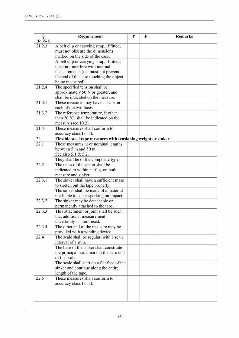
Results of tests if sampling is used
Sampling plan26
Inspection level: : Single / Double (delete as necessary)
Actual size of lot: Sample size code letter: Recommended sample size: AQL: Acceptance number: First:27 Second:28
Rejection number: First: Second:
Test Actual number of
rejects Reasons for rejection
First Second Visual inspection Scale accuracy and large scale linearity
Scale interval accuracy Scale interval linearity Accuracy of other metrological components29
(specify):
Indicating device – agreement with blade reading
Indicating device – hysteresis
Total number of rejects for lot:
Accept/reject lot:
Comments:
26 See OIML R 35-2, 10.1, ISO 2859-1 27 Single sampling plan or first sample of double sampling plan 28 Second sample of double sampling plan 29 E.g. dimensioned tape case, sinker.

OIML R 35-3:2011 (E)
50
Annex A (Mandatory)
List of documents received from the manufacturer concerning the type (R 35-2, 5)
Document reference Date Brief description
Comments:

OIML R 35-3:2011 (E)
51
Annex B (Mandatory)
List of test equipment used in examinations and tests
Parameter measured or
applied
Manu-facturer
Instru-ment/
Equip-ment
Model number
Serial number
Calibration date Used in test no.
(R 35-2, subclause no.) Last Next
Comments:
OIML R 35-3:2011 (E)
52
Annex C (Mandatory, when applicable)
List of simulators used in examinations and tests
System or module name Reference number Function
Comments:
Simulator description and drawings, block diagram, etc., should be attached to the report, if available.


![OIML R 49-1 (E) 2006 - ZEN SERVIS International recommendation OIML R...OIML D 11 ]. OIML R 49-1: 2006 (E) 7 2.2.10 Significant fault Fault, the magnitude of which is greater than](https://img.pdfslide.net/doc/110x75/5add5cf97f8b9a9d4d8d12e1/oiml-r-49-1-e-2006-zen-international-recommendation-oiml-roiml-d-11-oiml.jpg)