Embed Size (px)
Citation preview
International
Standard Cockpit
- 1 – Copyright © 2006 By FSD International
All Rights Reserved For use with Microsoft Flight Simulator only
Introduction This Pilot's Guide provides information about the standard panel for the FSD Piper PA34 Seneca V, including the Digital Display Monitoring Panel (DDMP).
Note
All images contained within this document, including screenshots and other displays, are for reference use only and are subject to change. The images contained herein may differ slightly from your actual equipment or display.
The instructions and warnings in this manual are not intended to replace the instructions and warnings for other equipment on your aircraft. It is critical that you as the pilot in command have a complete understanding of the warnings, operating instructions, and limitations for all equipment installed on your aircraft. FSD strongly recommends that you use the EHSI/MFD only under VFR conditions until you are very familiar with the instrumentation. All materials copyrighted including images that represent this software Copyright© 2006 FSD International. All rights reserved.
This space left intentionally blank.
International
Standard Cockpit
- 2 – Copyright © 2006 By FSD International
All Rights Reserved For use with Microsoft Flight Simulator only
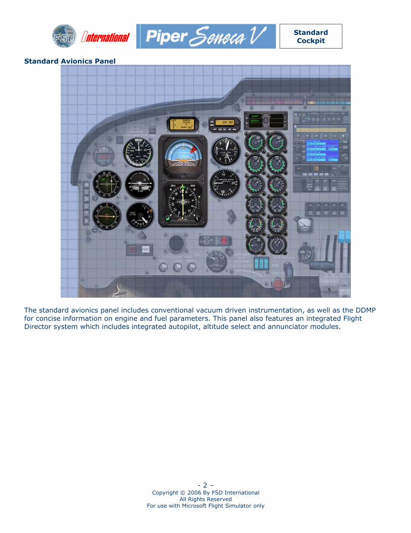
Standard Avionics Panel
The standard avionics panel includes conventional vacuum driven instrumentation, as well as the DDMP for concise information on engine and fuel parameters. This panel also features an integrated Flight Director system which includes integrated autopilot, altitude select and annunciator modules.
International
Standard Cockpit
- 3 – Copyright © 2006 By FSD International
All Rights Reserved For use with Microsoft Flight Simulator only
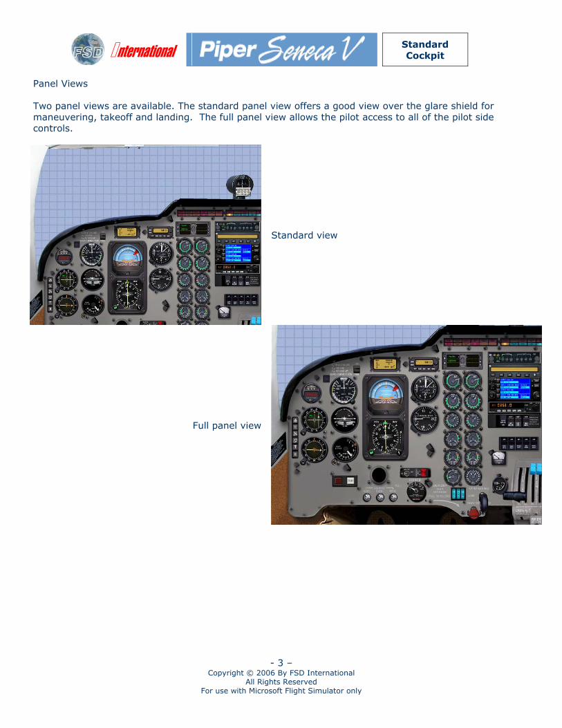
Panel Views Two panel views are available. The standard panel view offers a good view over the glare shield for maneuvering, takeoff and landing. The full panel view allows the pilot access to all of the pilot side controls.
Standard view
Full panel view
International
Standard Cockpit
- 4 – Copyright © 2006 By FSD International
All Rights Reserved For use with Microsoft Flight Simulator only
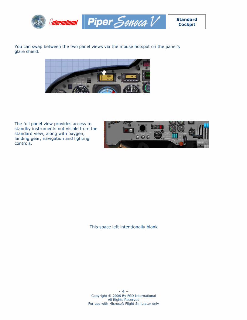
You can swap between the two panel views via the mouse hotspot on the panel’s glare shield.
The full panel view provides access to standby instruments not visible from the standard view, along with oxygen, landing gear, navigation and lighting controls.
This space left intentionally blank
International
Standard Cockpit
- 5 – Copyright © 2006 By FSD International
All Rights Reserved For use with Microsoft Flight Simulator only
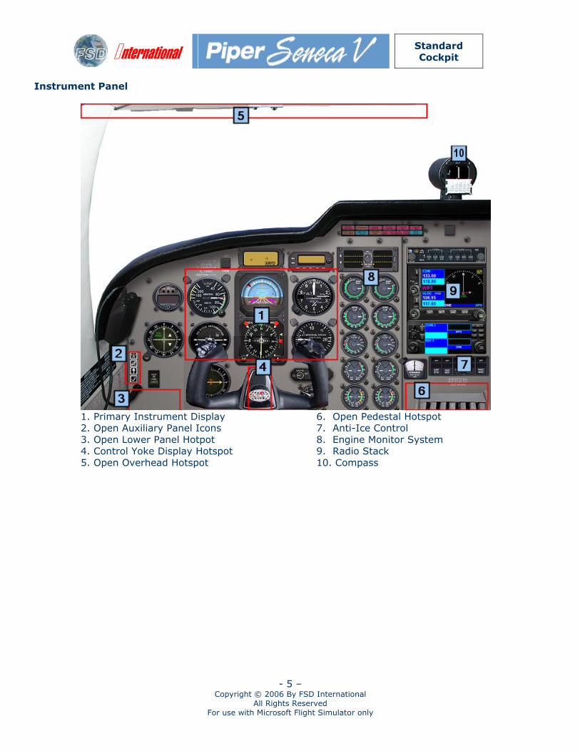
Instrument Panel
1. Primary Instrument Display 2. Open Auxiliary Panel Icons 3. Open Lower Panel Hotpot 4. Control Yoke Display Hotspot 5. Open Overhead Hotspot
6. Open Pedestal Hotspot 7. Anti-Ice Control 8. Engine Monitor System 9. Radio Stack 10. Compass
International
Standard Cockpit
- 6 – Copyright © 2006 By FSD International
All Rights Reserved For use with Microsoft Flight Simulator only
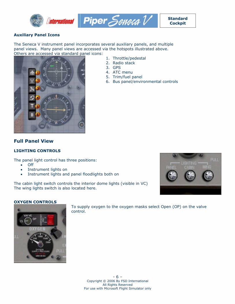
Auxiliary Panel Icons The Seneca V instrument panel incorporates several auxiliary panels, and multiple panel views. Many panel views are accessed via the hotspots illustrated above. Others are accessed via standard panel icons:
1. Throttle/pedestal 2. Radio stack 3. GPS 4. ATC menu 5. Trim/fuel panel 6. Bus panel/environmental controls
Full Panel View LIGHTING CONTROLS The panel light control has three positions:
• Off • Instrument lights on • Instrument lights and panel floodlights both on
The cabin light switch controls the interior dome lights (visible in VC) The wing lights switch is also located here.
OXYGEN CONTROLS
To supply oxygen to the oxygen masks select Open (OP) on the valve control.
International
Standard Cockpit
- 7 – Copyright © 2006 By FSD International
All Rights Reserved For use with Microsoft Flight Simulator only
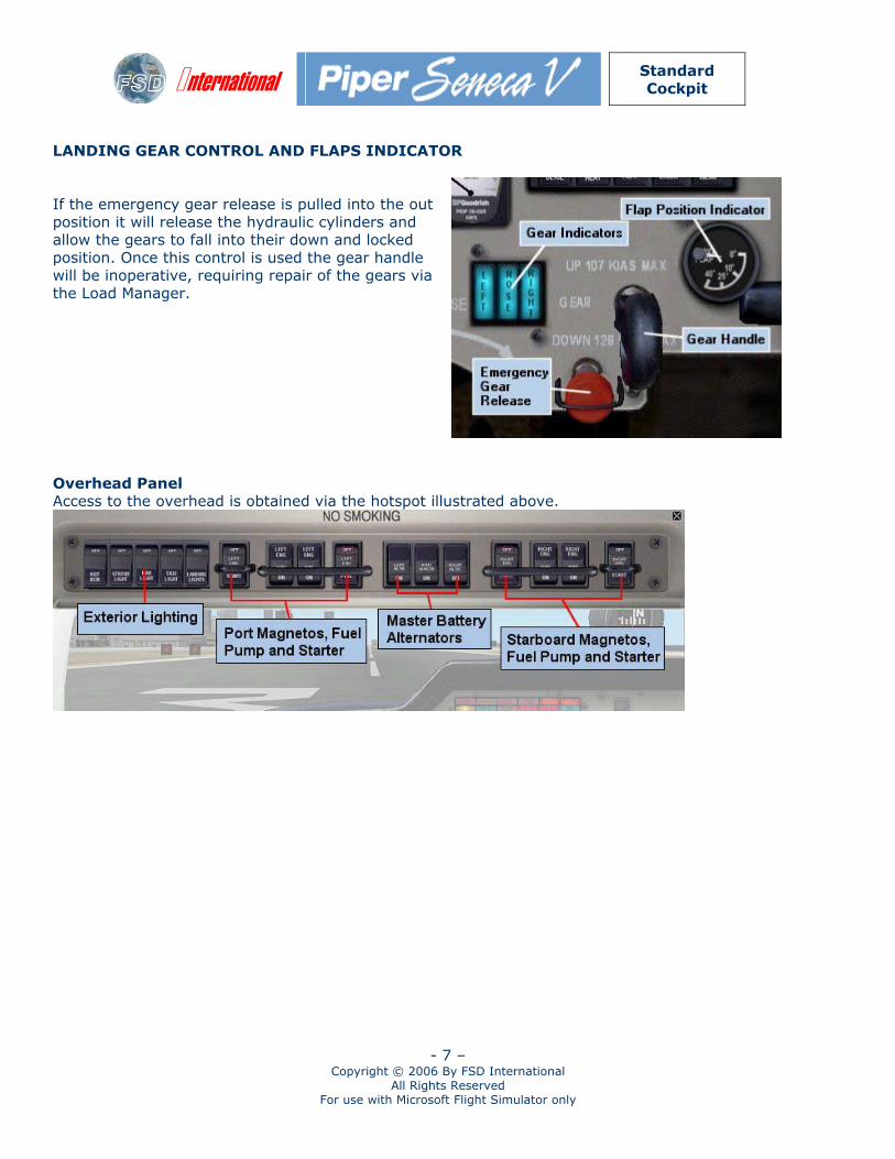
LANDING GEAR CONTROL AND FLAPS INDICATOR If the emergency gear release is pulled into the out position it will release the hydraulic cylinders and allow the gears to fall into their down and locked position. Once this control is used the gear handle will be inoperative, requiring repair of the gears via the Load Manager.
Overhead Panel Access to the overhead is obtained via the hotspot illustrated above.
International
Standard Cockpit
- 8 – Copyright © 2006 By FSD International
All Rights Reserved For use with Microsoft Flight Simulator only
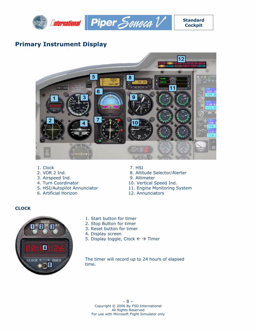
Primary Instrument Display
1. Clock 2. VOR 2 Ind. 3. Airspeed Ind. 4. Turn Coordinator 5. HSI/Autopilot Annunciator 6. Artificial Horizon
7. HSI 8. Altitude Selector/Alerter 9. Altimeter 10. Vertical Speed Ind. 11. Engine Monitoring System 12. Annunciators
CLOCK
1. Start button for timer 2. Stop Button for timer 3. Reset button for timer 4. Display screen 5. Display toggle, Clock Timer The timer will record up to 24 hours of elapsed time.
International
Standard Cockpit
- 9 – Copyright © 2006 By FSD International
All Rights Reserved For use with Microsoft Flight Simulator only
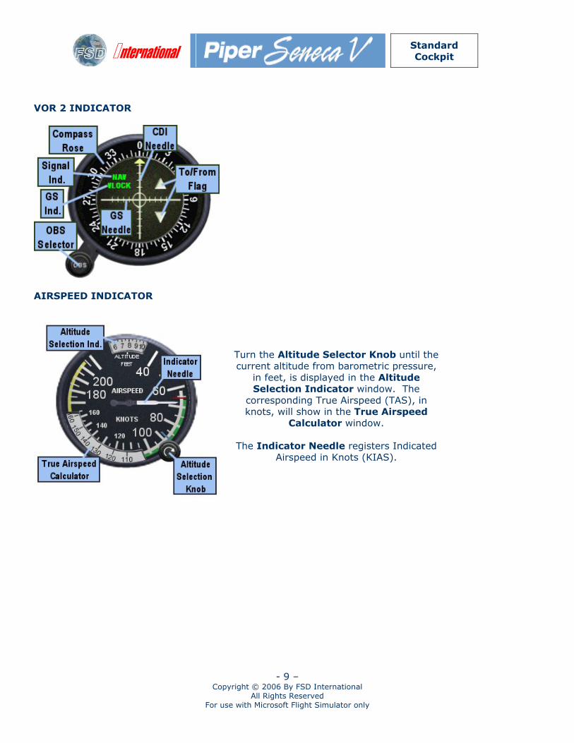
VOR 2 INDICATOR
AIRSPEED INDICATOR
Turn the Altitude Selector Knob until the current altitude from barometric pressure,
in feet, is displayed in the Altitude Selection Indicator window. The
corresponding True Airspeed (TAS), in knots, will show in the True Airspeed
Calculator window.
The Indicator Needle registers Indicated Airspeed in Knots (KIAS).
International
Standard Cockpit
- 10 – Copyright © 2006 By FSD International
All Rights Reserved For use with Microsoft Flight Simulator only
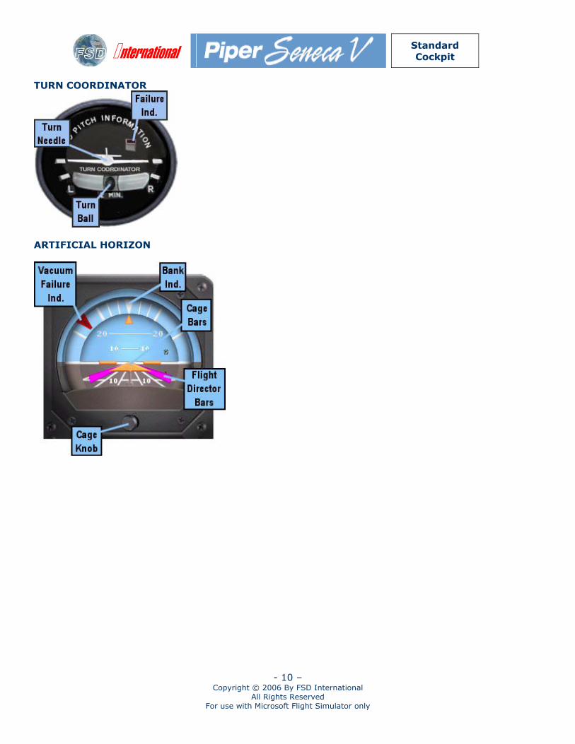
TURN COORDINATOR
ARTIFICIAL HORIZON
International
Standard Cockpit
- 11 – Copyright © 2006 By FSD International
All Rights Reserved For use with Microsoft Flight Simulator only
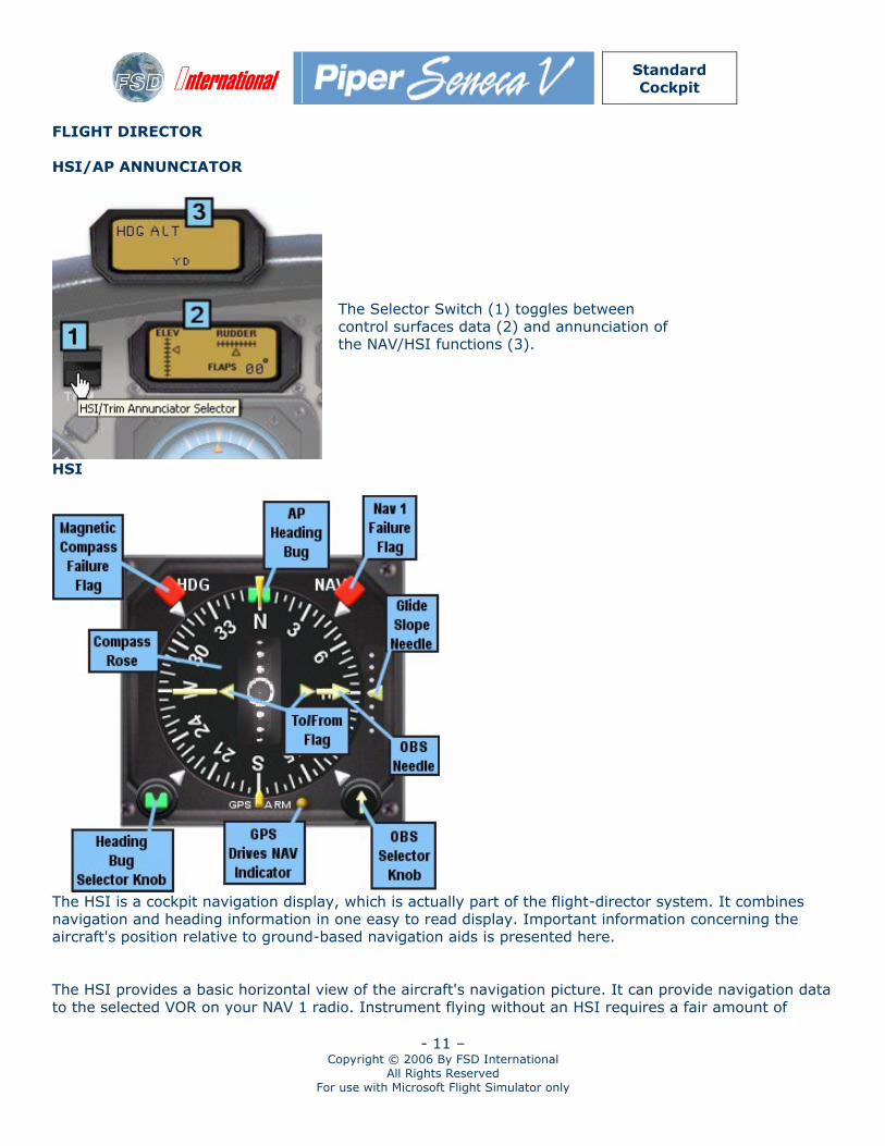
FLIGHT DIRECTOR HSI/AP ANNUNCIATOR
The Selector Switch (1) toggles between control surfaces data (2) and annunciation of the NAV/HSI functions (3).
HSI
The HSI is a cockpit navigation display, which is actually part of the flight-director system. It combines navigation and heading information in one easy to read display. Important information concerning the aircraft's position relative to ground-based navigation aids is presented here. The HSI provides a basic horizontal view of the aircraft's navigation picture. It can provide navigation data to the selected VOR on your NAV 1 radio. Instrument flying without an HSI requires a fair amount of
International
Standard Cockpit
- 12 – Copyright © 2006 By FSD International
All Rights Reserved For use with Microsoft Flight Simulator only
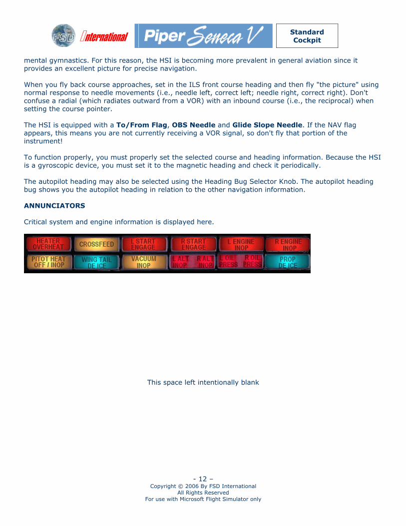
mental gymnastics. For this reason, the HSI is becoming more prevalent in general aviation since it provides an excellent picture for precise navigation. When you fly back course approaches, set in the ILS front course heading and then fly "the picture" using normal response to needle movements (i.e., needle left, correct left; needle right, correct right). Don't confuse a radial (which radiates outward from a VOR) with an inbound course (i.e., the reciprocal) when setting the course pointer. The HSI is equipped with a To/From Flag, OBS Needle and Glide Slope Needle. If the NAV flag appears, this means you are not currently receiving a VOR signal, so don't fly that portion of the instrument! To function properly, you must properly set the selected course and heading information. Because the HSI is a gyroscopic device, you must set it to the magnetic heading and check it periodically. The autopilot heading may also be selected using the Heading Bug Selector Knob. The autopilot heading bug shows you the autopilot heading in relation to the other navigation information. ANNUNCIATORS Critical system and engine information is displayed here.
This space left intentionally blank
International
Standard Cockpit
- 13 – Copyright © 2006 By FSD International
All Rights Reserved For use with Microsoft Flight Simulator only
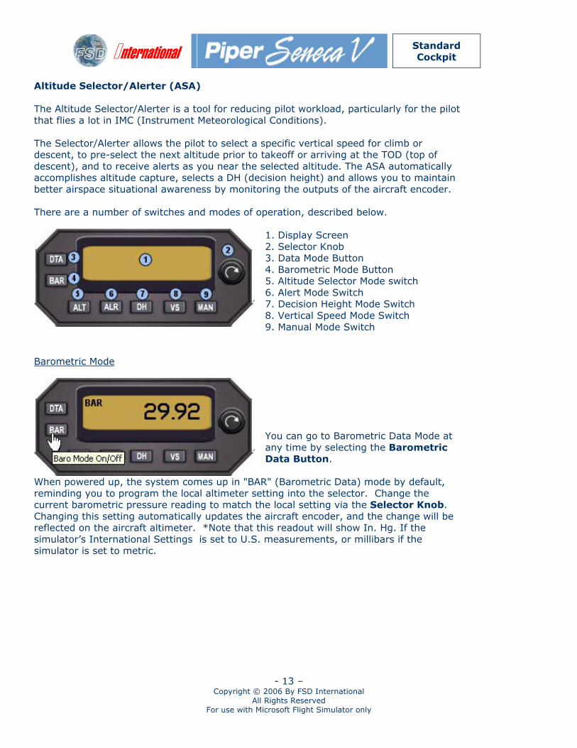
Altitude Selector/Alerter (ASA) The Altitude Selector/Alerter is a tool for reducing pilot workload, particularly for the pilot that flies a lot in IMC (Instrument Meteorological Conditions). The Selector/Alerter allows the pilot to select a specific vertical speed for climb or descent, to pre-select the next altitude prior to takeoff or arriving at the TOD (top of descent), and to receive alerts as you near the selected altitude. The ASA automatically accomplishes altitude capture, selects a DH (decision height) and allows you to maintain better airspace situational awareness by monitoring the outputs of the aircraft encoder. There are a number of switches and modes of operation, described below.
1. Display Screen 2. Selector Knob 3. Data Mode Button 4. Barometric Mode Button 5. Altitude Selector Mode switch 6. Alert Mode Switch 7. Decision Height Mode Switch 8. Vertical Speed Mode Switch 9. Manual Mode Switch
Barometric Mode
You can go to Barometric Data Mode at any time by selecting the Barometric Data Button.
When powered up, the system comes up in "BAR" (Barometric Data) mode by default, reminding you to program the local altimeter setting into the selector. Change the current barometric pressure reading to match the local setting via the Selector Knob. Changing this setting automatically updates the aircraft encoder, and the change will be reflected on the aircraft altimeter. *Note that this readout will show In. Hg. If the simulator’s International Settings is set to U.S. measurements, or millibars if the simulator is set to metric.
International
Standard Cockpit
- 14 – Copyright © 2006 By FSD International
All Rights Reserved For use with Microsoft Flight Simulator only
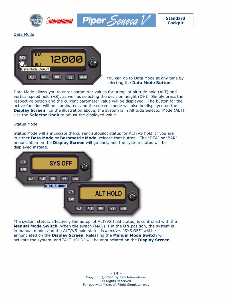
Data Mode
You can go to Data Mode at any time by selecting the Data Mode Button.
Data Mode allows you to enter parameter values for autopilot altitude hold (ALT) and vertical speed hold (VS), as well as selecting the decision height (DH). Simply press the respective button and the current parameter value will be displayed. The button for the active function will be illuminated, and the current mode will also be displayed on the Display Screen. In the illustration above, the system is in Altitude Selector Mode (ALT). Use the Selector Knob to adjust the displayed value. Status Mode Status Mode will annunciate the current autopilot status for ALT/VS hold. If you are in either Data Mode or Barometric Mode, release that button. The “DTA” or “BAR” annunciation on the Display Screen will go dark, and the system status will be displayed instead.
The system status, effectively the autopilot ALT/VS hold status, is controlled with the Manual Mode Switch. When the switch (MAN) is in the ON position, the system is in manual mode, and the ALT/VS hold status is inactive. “SYS OFF” will be annunciated on the Display Screen. Releasing the Manual Mode Switch will activate the system, and “ALT HOLD” will be annunciated on the Display Screen.
International
Standard Cockpit
- 15 – Copyright © 2006 By FSD International
All Rights Reserved For use with Microsoft Flight Simulator only
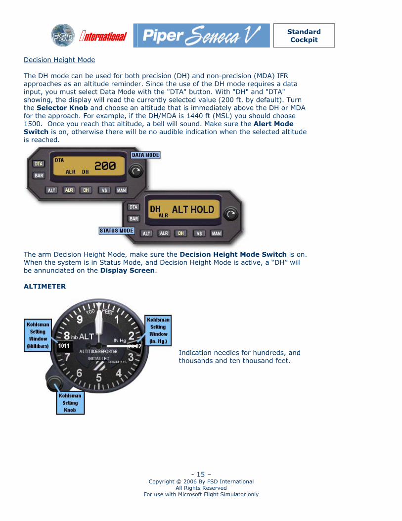
Decision Height Mode The DH mode can be used for both precision (DH) and non-precision (MDA) IFR approaches as an altitude reminder. Since the use of the DH mode requires a data input, you must select Data Mode with the "DTA" button. With "DH" and "DTA" showing, the display will read the currently selected value (200 ft. by default). Turn the Selector Knob and choose an altitude that is immediately above the DH or MDA for the approach. For example, if the DH/MDA is 1440 ft (MSL) you should choose 1500. Once you reach that altitude, a bell will sound. Make sure the Alert Mode Switch is on, otherwise there will be no audible indication when the selected altitude is reached.
The arm Decision Height Mode, make sure the Decision Height Mode Switch is on. When the system is in Status Mode, and Decision Height Mode is active, a “DH” will be annunciated on the Display Screen. ALTIMETER
Indication needles for hundreds, and thousands and ten thousand feet.
International
Standard Cockpit
- 16 – Copyright © 2006 By FSD International
All Rights Reserved For use with Microsoft Flight Simulator only
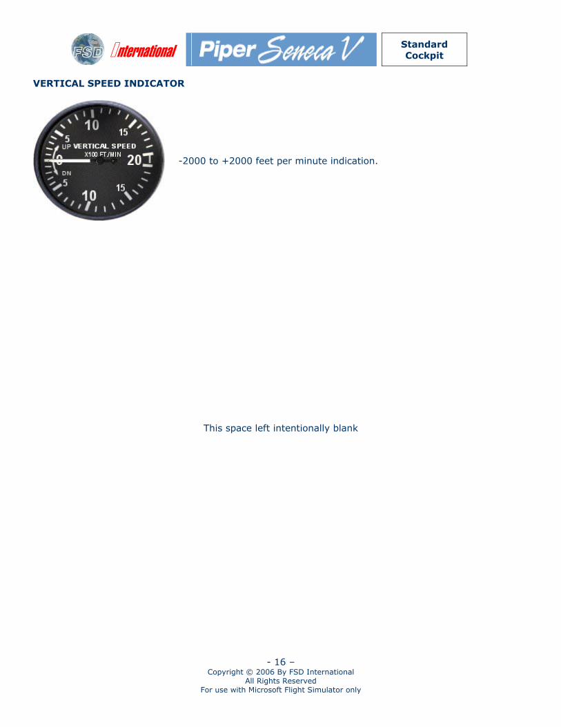
VERTICAL SPEED INDICATOR
-2000 to +2000 feet per minute indication.
This space left intentionally blank
International
Standard Cockpit
- 17 – Copyright © 2006 By FSD International
All Rights Reserved For use with Microsoft Flight Simulator only
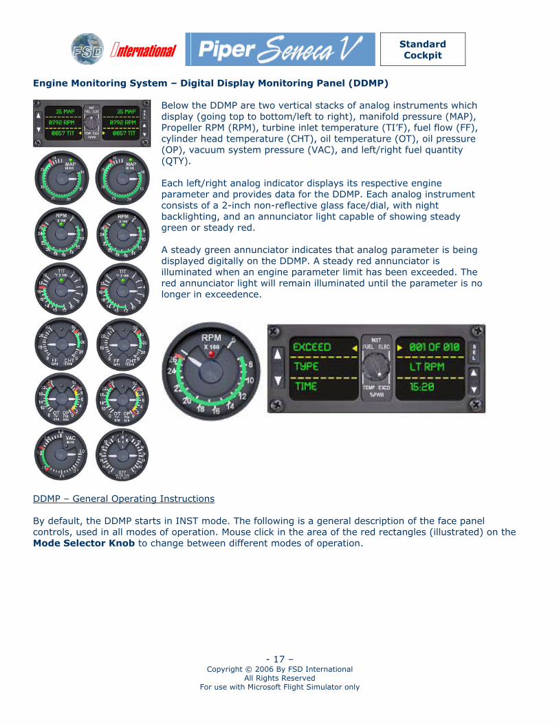
Engine Monitoring System – Digital Display Monitoring Panel (DDMP)
Below the DDMP are two vertical stacks of analog instruments which display (going top to bottom/left to right), manifold pressure (MAP), Propeller RPM (RPM), turbine inlet temperature (TI’F), fuel flow (FF), cylinder head temperature (CHT), oil temperature (OT), oil pressure (OP), vacuum system pressure (VAC), and left/right fuel quantity (QTY). Each left/right analog indicator displays its respective engine parameter and provides data for the DDMP. Each analog instrument consists of a 2-inch non-reflective glass face/dial, with night backlighting, and an annunciator light capable of showing steady green or steady red. A steady green annunciator indicates that analog parameter is being displayed digitally on the DDMP. A steady red annunciator is illuminated when an engine parameter limit has been exceeded. The red annunciator light will remain illuminated until the parameter is no longer in exceedence.
DDMP – General Operating Instructions By default, the DDMP starts in INST mode. The following is a general description of the face panel controls, used in all modes of operation. Mouse click in the area of the red rectangles (illustrated) on the Mode Selector Knob to change between different modes of operation.
International
Standard Cockpit
- 18 – Copyright © 2006 By FSD International
All Rights Reserved For use with Microsoft Flight Simulator only
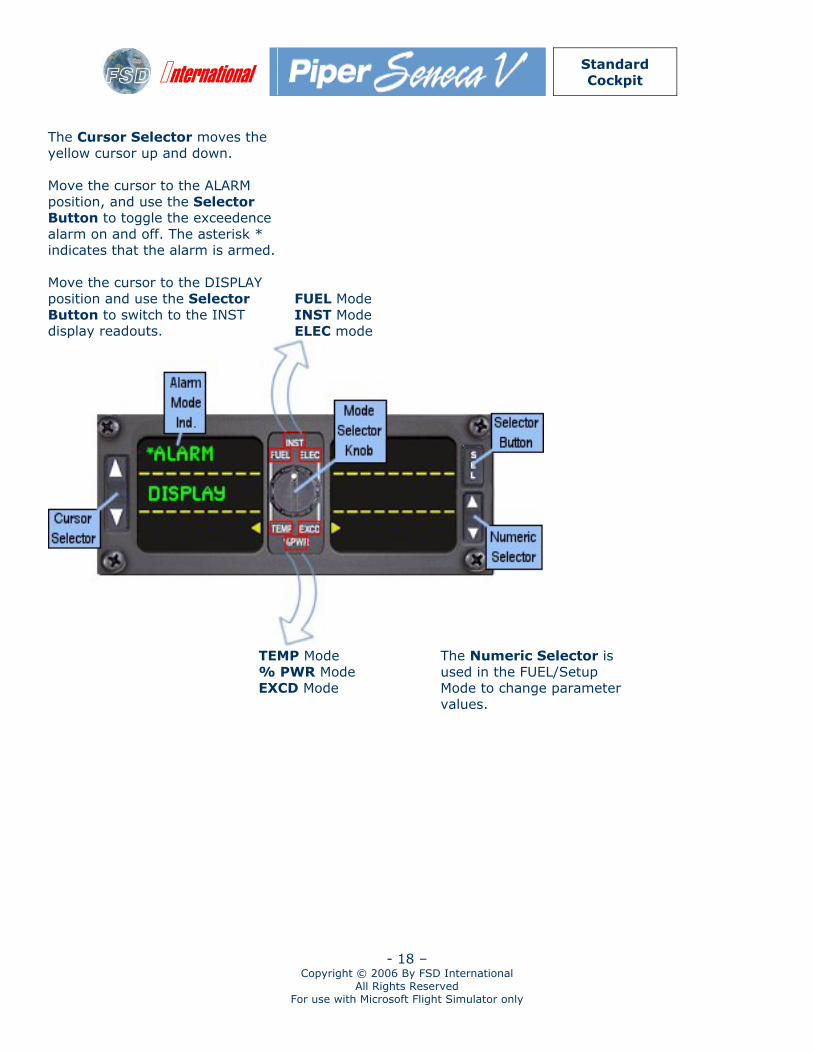
The Cursor Selector moves the yellow cursor up and down. Move the cursor to the ALARM position, and use the Selector Button to toggle the exceedence alarm on and off. The asterisk * indicates that the alarm is armed. Move the cursor to the DISPLAY position and use the Selector Button to switch to the INST display readouts.
FUEL Mode INST Mode ELEC mode
TEMP Mode
% PWR Mode EXCD Mode
The Numeric Selector is used in the FUEL/Setup Mode to change parameter values.
International
Standard Cockpit
- 19 – Copyright © 2006 By FSD International
All Rights Reserved For use with Microsoft Flight Simulator only
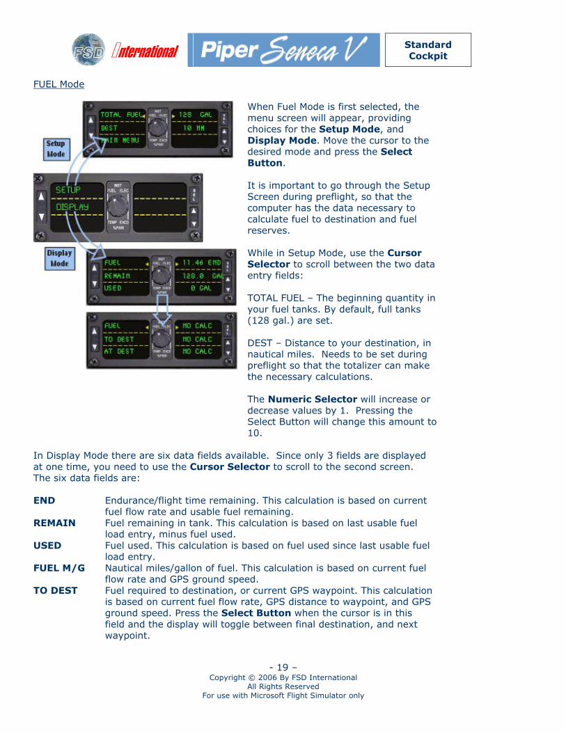
FUEL Mode
When Fuel Mode is first selected, the menu screen will appear, providing choices for the Setup Mode, and Display Mode. Move the cursor to the desired mode and press the Select Button.
It is important to go through the Setup Screen during preflight, so that the computer has the data necessary to calculate fuel to destination and fuel reserves. While in Setup Mode, use the Cursor Selector to scroll between the two data entry fields: TOTAL FUEL – The beginning quantity in your fuel tanks. By default, full tanks (128 gal.) are set. DEST – Distance to your destination, in nautical miles. Needs to be set during preflight so that the totalizer can make the necessary calculations. The Numeric Selector will increase or decrease values by 1. Pressing the Select Button will change this amount to 10.
In Display Mode there are six data fields available. Since only 3 fields are displayed at one time, you need to use the Cursor Selector to scroll to the second screen. The six data fields are: END Endurance/flight time remaining. This calculation is based on current
fuel flow rate and usable fuel remaining. REMAIN Fuel remaining in tank. This calculation is based on last usable fuel
load entry, minus fuel used. USED Fuel used. This calculation is based on fuel used since last usable fuel
load entry. FUEL M/G Nautical miles/gallon of fuel. This calculation is based on current fuel
flow rate and GPS ground speed. TO DEST Fuel required to destination, or current GPS waypoint. This calculation
is based on current fuel flow rate, GPS distance to waypoint, and GPS ground speed. Press the Select Button when the cursor is in this field and the display will toggle between final destination, and next waypoint.
International
Standard Cockpit
- 20 – Copyright © 2006 By FSD International
All Rights Reserved For use with Microsoft Flight Simulator only
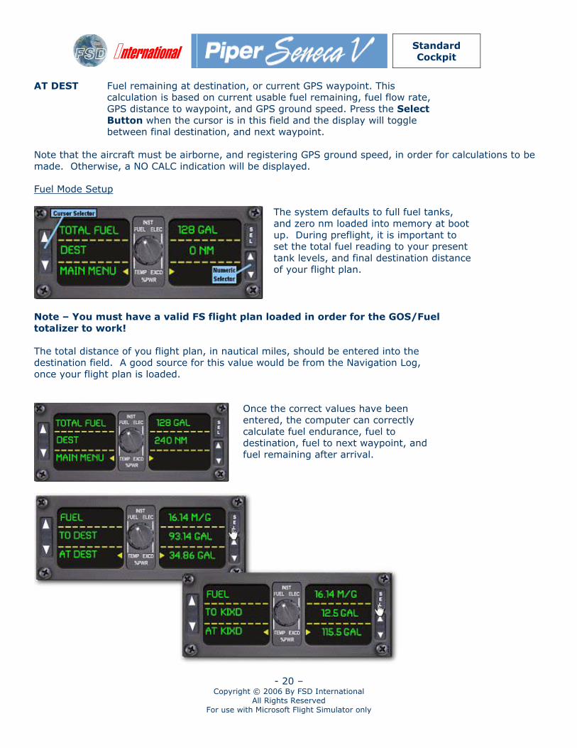
AT DEST Fuel remaining at destination, or current GPS waypoint. This calculation is based on current usable fuel remaining, fuel flow rate, GPS distance to waypoint, and GPS ground speed. Press the Select Button when the cursor is in this field and the display will toggle between final destination, and next waypoint.
Note that the aircraft must be airborne, and registering GPS ground speed, in order for calculations to be made. Otherwise, a NO CALC indication will be displayed.
Fuel Mode Setup
The system defaults to full fuel tanks, and zero nm loaded into memory at boot up. During preflight, it is important to set the total fuel reading to your present tank levels, and final destination distance of your flight plan.
Note – You must have a valid FS flight plan loaded in order for the GOS/Fuel totalizer to work! The total distance of you flight plan, in nautical miles, should be entered into the destination field. A good source for this value would be from the Navigation Log, once your flight plan is loaded.
Once the correct values have been entered, the computer can correctly calculate fuel endurance, fuel to destination, fuel to next waypoint, and fuel remaining after arrival.
International
Standard Cockpit
- 21 – Copyright © 2006 By FSD International
All Rights Reserved For use with Microsoft Flight Simulator only
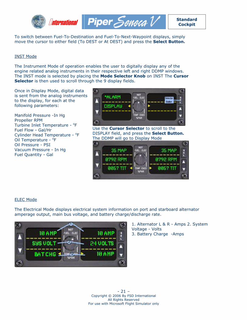
To switch between Fuel-To-Destination and Fuel-To-Next-Waypoint displays, simply move the cursor to either field (To DEST or At DEST) and press the Select Button. INST Mode The Instrument Mode of operation enables the user to digitally display any of the engine related analog instruments in their respective left and right DDMP windows. The INST mode is selected by placing the Mode Selector Knob on INST The Cursor Selector is then used to scroll through the 9 display fields.
Use the Cursor Selector to scroll to the DISPLAY field, and press the Select Button. The DDMP will go to Display Mode
Once in Display Mode, digital data is sent from the analog instruments to the display, for each at the following parameters: Manifold Pressure -In Hg Propeller RPM Turbine Inlet Temperature - oF Fuel Flow - Gal/Hr Cylinder Head Temperature - oF Oil Temperature - oF Oil Pressure - PSI Vacuum Pressure - In Hg Fuel Quantity - Gal
ELEC Mode The Electrical Mode displays electrical system information on port and starboard alternator amperage output, main bus voltage, and battery charge/discharge rate.
1. Alternator L & R - Amps 2. System Voltage - Volts 3. Battery Charge -Amps
International
Standard Cockpit
- 22 – Copyright © 2006 By FSD International
All Rights Reserved For use with Microsoft Flight Simulator only
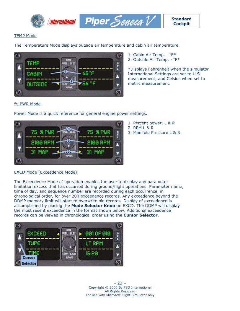
TEMP Mode The Temperature Mode displays outside air temperature and cabin air temperature.
1. Cabin Air Temp. - oF* 2. Outside Air Temp. - oF* *Displays Fahrenheit when the simulator International Settings are set to U.S. measurement, and Celsius when set to metric measurement.
% PWR Mode Power Mode is a quick reference for general engine power settings.
1. Percent power, L & R 2. RPM L & R 3. Manifold Pressure L & R
EXCD Mode (Exceedence Mode) The Exceedence Mode of operation enables the user to display any parameter limitation excess that has occurred during ground/flight operations. Parameter name, time of day, and sequence number are recorded during each occurrence, in chronological order, for over 200 exceedence records. Any exceedence beyond the DDMP memory limit will start to overwrite old records. Display of exceedence is accomplished by placing the Mode Selector Knob on EXCD. The DDMP will display the most resent exceedence in the format shown below. Additional exceedence records can be viewed in chronological order using the Cursor Selector.
International
Standard Cockpit
- 23 – Copyright © 2006 By FSD International
All Rights Reserved For use with Microsoft Flight Simulator only
The EXCD display and show the parameter in exceedence according to the following codes: LO VLT HI VLT LT MAP RT MAP LT RPM RT RPM LT TIT RT TIT LT CHT RT CHT
Low System Voltage High System Voltage High Left MAP High Right MAP High Left RPM High Right RPM High Left TIT High Right TIT High Left CHT High Right CHT
LT OT RT OT LT LOP RT LOP LT HOP RT HOP LO VAC HI VAC LFQ RFQ
High Left Oil Temp. High Right Oil Temp. Low Left Oil Press. Low Right Oil Press. High Left Oil Press. High Right Oil Press. Low Vacuum High Vacuum Low Left Fuel Qty Low Right Fuel Qty
Pedestal
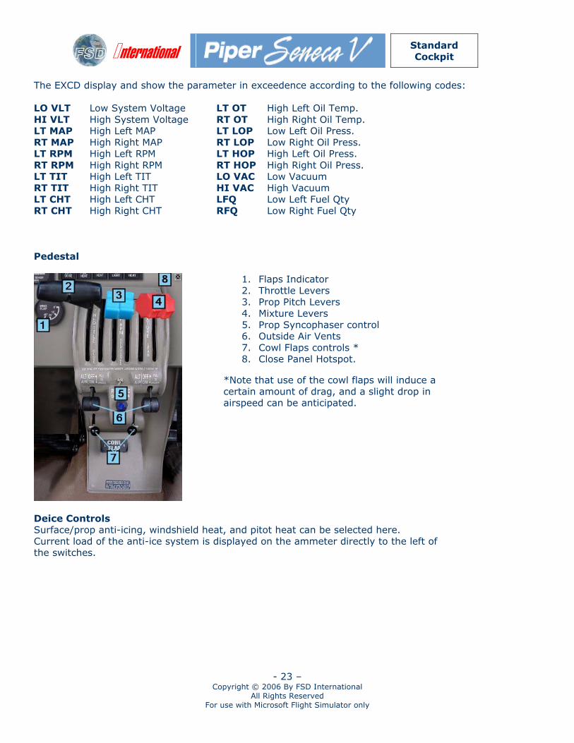
1. Flaps Indicator 2. Throttle Levers 3. Prop Pitch Levers 4. Mixture Levers 5. Prop Syncophaser control 6. Outside Air Vents 7. Cowl Flaps controls * 8. Close Panel Hotspot.
*Note that use of the cowl flaps will induce a certain amount of drag, and a slight drop in airspeed can be anticipated.
Deice Controls Surface/prop anti-icing, windshield heat, and pitot heat can be selected here. Current load of the anti-ice system is displayed on the ammeter directly to the left of the switches.
International
Standard Cockpit
- 24 – Copyright © 2006 By FSD International
All Rights Reserved For use with Microsoft Flight Simulator only
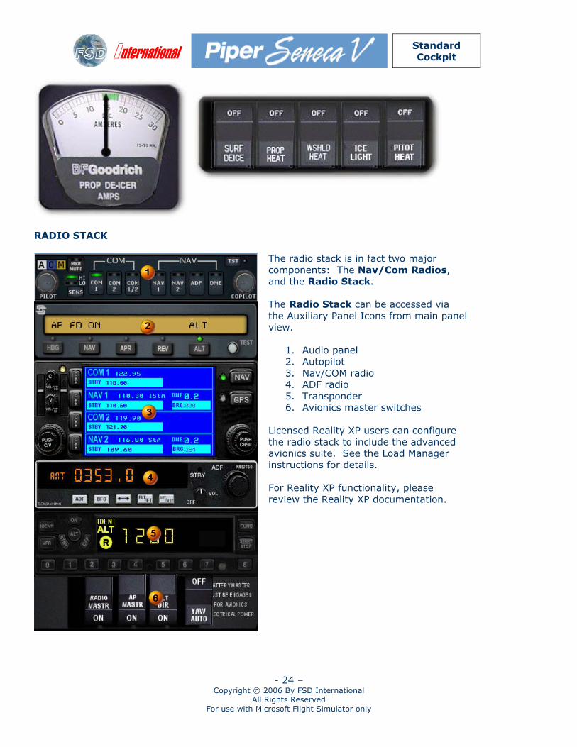
RADIO STACK
The radio stack is in fact two major components: The Nav/Com Radios, and the Radio Stack. The Radio Stack can be accessed via the Auxiliary Panel Icons from main panel view.
1. Audio panel 2. Autopilot 3. Nav/COM radio 4. ADF radio 5. Transponder 6. Avionics master switches
Licensed Reality XP users can configure the radio stack to include the advanced avionics suite. See the Load Manager instructions for details. For Reality XP functionality, please review the Reality XP documentation.
International
Standard Cockpit
- 25 – Copyright © 2006 By FSD International
All Rights Reserved For use with Microsoft Flight Simulator only
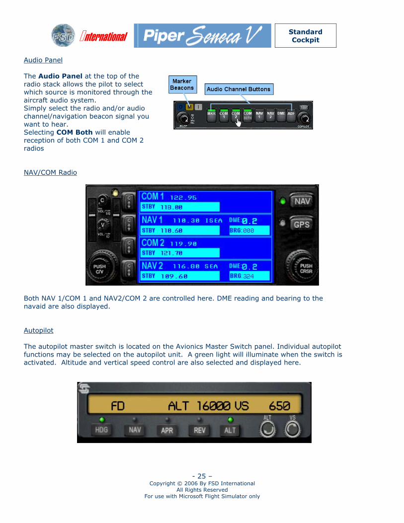
Audio Panel The Audio Panel at the top of the radio stack allows the pilot to select which source is monitored through the aircraft audio system. Simply select the radio and/or audio channel/navigation beacon signal you want to hear. Selecting COM Both will enable reception of both COM 1 and COM 2 radios NAV/COM Radio
Both NAV 1/COM 1 and NAV2/COM 2 are controlled here. DME reading and bearing to the navaid are also displayed. Autopilot The autopilot master switch is located on the Avionics Master Switch panel. Individual autopilot functions may be selected on the autopilot unit. A green light will illuminate when the switch is activated. Altitude and vertical speed control are also selected and displayed here.
International
Standard Cockpit
- 26 – Copyright © 2006 By FSD International
All Rights Reserved For use with Microsoft Flight Simulator only
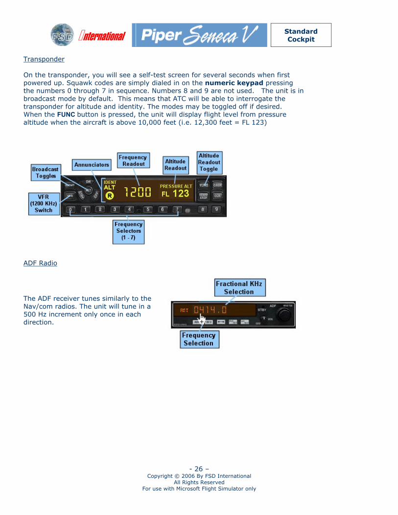
Transponder On the transponder, you will see a self-test screen for several seconds when first powered up. Squawk codes are simply dialed in on the numeric keypad pressing the numbers 0 through 7 in sequence. Numbers 8 and 9 are not used. The unit is in broadcast mode by default. This means that ATC will be able to interrogate the transponder for altitude and identity. The modes may be toggled off if desired. When the FUNC button is pressed, the unit will display flight level from pressure altitude when the aircraft is above 10,000 feet (i.e. 12,300 feet = FL 123)
ADF Radio
The ADF receiver tunes similarly to the Nav/com radios. The unit will tune in a 500 Hz increment only once in each direction.
International
Standard Cockpit
- 27 – Copyright © 2006 By FSD International
All Rights Reserved For use with Microsoft Flight Simulator only
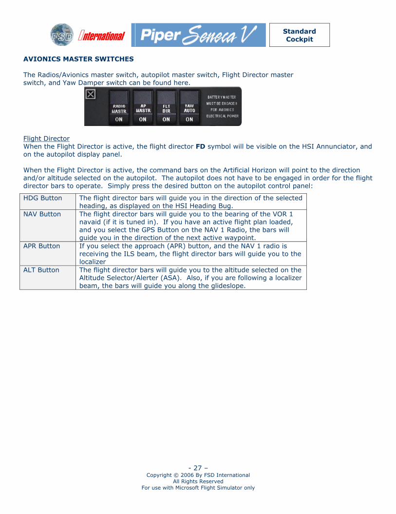
AVIONICS MASTER SWITCHES The Radios/Avionics master switch, autopilot master switch, Flight Director master switch, and Yaw Damper switch can be found here.
Flight Director When the Flight Director is active, the flight director FD symbol will be visible on the HSI Annunciator, and on the autopilot display panel. When the Flight Director is active, the command bars on the Artificial Horizon will point to the direction and/or altitude selected on the autopilot. The autopilot does not have to be engaged in order for the flight director bars to operate. Simply press the desired button on the autopilot control panel:
HDG Button The flight director bars will guide you in the direction of the selected heading, as displayed on the HSI Heading Bug.
NAV Button The flight director bars will guide you to the bearing of the VOR 1 navaid (if it is tuned in). If you have an active flight plan loaded, and you select the GPS Button on the NAV 1 Radio, the bars will guide you in the direction of the next active waypoint.
APR Button If you select the approach (APR) button, and the NAV 1 radio is receiving the ILS beam, the flight director bars will guide you to the localizer
ALT Button The flight director bars will guide you to the altitude selected on the Altitude Selector/Alerter (ASA). Also, if you are following a localizer beam, the bars will guide you along the glideslope.
International
Standard Cockpit
- 28 – Copyright © 2006 By FSD International
All Rights Reserved For use with Microsoft Flight Simulator only
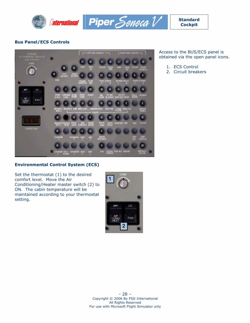
Bus Panel/ECS Controls
Access to the BUS/ECS panel is obtained via the open panel icons.
1. ECS Control 2. Circuit breakers
Environmental Control System (ECS) Set the thermostat (1) to the desired comfort level. Move the Air Conditioning/Heater master switch (2) to ON. The cabin temperature will be maintained according to your thermostat setting.


![District Disaster Management Plan [DDMP] For Betul, … Disaster Management Plan [DDMP] For Betul, MP For School of Good Governance & Policy Analysis, Government of Madhya Pradesh,](https://img.pdfslide.net/doc/110x75/5acc415a7f8b9a73128c9ec4/district-disaster-management-plan-ddmp-for-betul-disaster-management-plan.jpg)
![District Disaster Management Plan [DDMP] Template · 2018-12-06 · Madhuri Swamy Intern SGGPA XIMB . District Disaster Management Plan [DDMP] ... Indira Sagar Dam (Satwas tehsil)](https://img.pdfslide.net/doc/110x75/5f3b289476952a74bc61cda4/district-disaster-management-plan-ddmp-2018-12-06-madhuri-swamy-intern-sggpa.jpg)


![SINGRAULI District Disaster Management Plan [DDMP]](https://img.pdfslide.net/doc/110x75/616a1e7511a7b741a34f0257/singrauli-district-disaster-management-plan-ddmp.jpg)


![District Disaster Management Plan [DDMP] For Betul, MP](https://img.pdfslide.net/doc/110x75/61f1c5596ee6ba04900f3658/district-disaster-management-plan-ddmp-for-betul-mp.jpg)