Embed Size (px)
Citation preview
International Symposium on Standards for UHV Transmission
1
3.1System Impacts on UHV Substation Equipment
On behalf of CIGRE WG A3.22
29-30 January 2009, New Delhi, India
Hiroki ItoMitsubishi Electric
Covenor, CIGRE WG A3.22
Scope: Review the state-of-the-art of project specific and national technical specifications for all substation equipment within the scope of CIGRE Study Committee A3 at voltages exceeding 800 kV. Recommend future specifications and standardizations of 1100 kV and 1200 kV equipment and provide technical backgrounds on the collected information to IEC TC17.
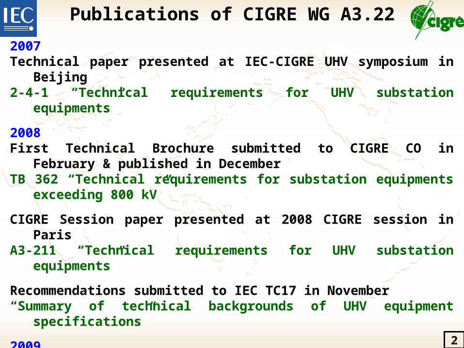
Publications of CIGRE WG A3.22
2007Technical paper presented at IEC-CIGRE UHV symposium in Beijing2-4-1 “Technical requirements for UHV substation equipments”
2008First Technical Brochure submitted to CIGRE CO in February & published in DecemberTB 362 “Technical requirements for substation equipments exceeding 800 kV”
CIGRE Session paper presented at 2008 CIGRE session in ParisA3-211 “Technical requirements for UHV substation equipments”
Recommendations submitted to IEC TC17 in November“Summary of technical backgrounds of UHV equipment specifications”
2009Technical paper presented at IEC-CIGRE UHV symposium in New Delhi3-1 “System impacts on UHV substation equipment”4-1 “CIGRE state of the art & prospects for equipment”
Second Technical Brochure will be submitted to A3 chairman in March“Background of technical specifications of substation equipment exceeding 800 kV”
2
3
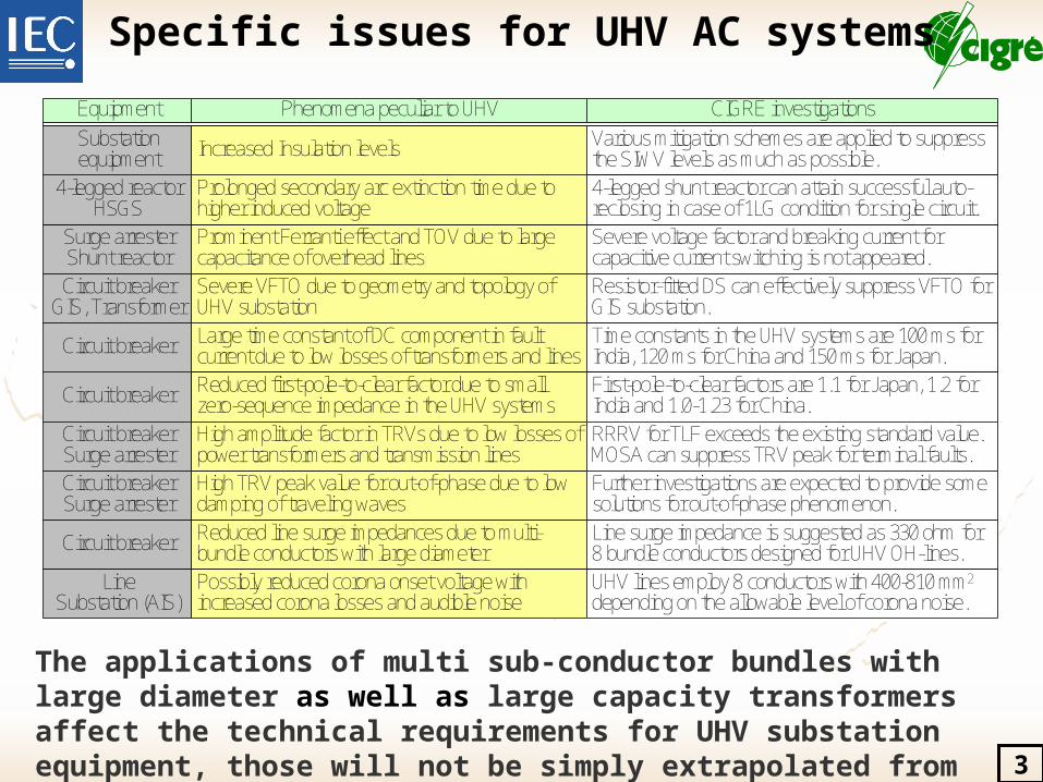
Specific issues for UHV AC systems
Prominent Ferranti effect and TOV due to large capacitance of overhead lines
Phenomena peculiar to UHVEquipment
Surge arresterShunt reactor
CIGRE investigations
Severe voltage factor and breaking current for capacitive current switching is not appeared.
Prolonged secondary arc extinction time due to higher induced voltage
4-legged reactorHSGS
Large time constant of DC component in fault current due to low losses of transformers and lines
Circuit breaker Reduced first-pole-to-clear factor due to small zero-sequence impedance in the UHV systems
Reduced line surge impedances due to multi-bundle conductors with large diameter
Circuit breaker
Severe VFTO due to geometry and topology of UHV substation
High TRV peak value for out-of-phase due to low damping of traveling waves
Circuit breaker
Possibly reduced corona onset voltage with increased corona losses and audible noise
LineSubstation (AIS)
Circuit breakerGIS, Transformer
High amplitude factor in TRVs due to low losses of power transformers and transmission lines
Circuit breakerSurge arresterCircuit breakerSurge arrester
Increased Insulation levelsSubstationequipment
Various mitigation schemes are applied to suppress the SIWV levels as much as possible.4-legged shunt reactor can attain successful auto-reclosing in case of 1LG condition for single circuit.
Resistor-fitted DS can effectively suppress VFTO for GIS substation.Time constants in the UHV systems are 100 ms for India, 120 ms for China and 150 ms for Japan.
Line surge impedance is suggested as 330 ohm for 8 bundle conductors designed for UHV OH-lines.
First-pole-to-clear factors are 1.1 for Japan, 1.2 for India and 1.0-1.23 for China.RRRV for TLF exceeds the existing standard value. MOSA can suppress TRV peak for terminal faults.Further investigations are expected to provide some solutions for out-of-phase phenomenon.
UHV lines employ 8 conductors with 400-810 mm2
depending on the allowable level of corona noise.
The applications of multi sub-conductor bundles with large diameter as well as large capacity transformers affect the technical requirements for UHV substation equipment, those will not be simply extrapolated from the existing standards up to 800 kV.
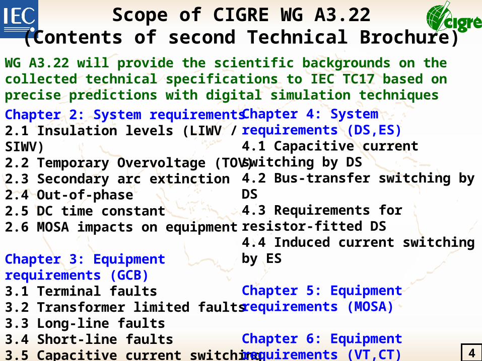
Chapter 2: System requirements2.1 Insulation levels (LIWV / SIWV)2.2 Temporary Overvoltage (TOV)2.3 Secondary arc extinction2.4 Out-of-phase2.5 DC time constant2.6 MOSA impacts on equipment
Chapter 3: Equipment requirements (GCB)3.1 Terminal faults3.2 Transformer limited faults3.3 Long-line faults3.4 Short-line faults3.5 Capacitive current switching3.6 Requirements for auxiliary equipment of CB
4
Scope of CIGRE WG A3.22(Contents of second Technical Brochure)
Chapter 4: System requirements (DS,ES)4.1 Capacitive current switching by DS4.2 Bus-transfer switching by DS4.3 Requirements for resistor-fitted DS4.4 Induced current switching by ES
Chapter 5: Equipment requirements (MOSA)
Chapter 6: Equipment requirements (VT,CT)
Chapter 7: Factory &Lab. Testing experience
Chapter 8: Field testing experience
WG A3.22 will provide the scientific backgrounds on the collected technical specifications to IEC TC17 based on precise predictions with digital simulation techniques
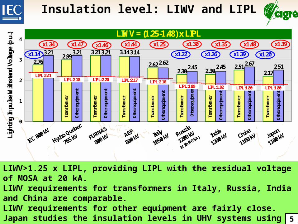
LIWV>1.25 x LIPL, providing LIPL with the residual voltage of MOSA at 20 kA. LIWV requirements for transformers in Italy, Russia, India and China are comparable.LIWV requirements for other equipment are fairly close.Japan studies the insulation levels in UHV systems using the EMTP analysis with a lightning current of 200kA-1s/70sWG A3.22 is investigating a limited survey on utilities’ policies on the insulation level.
0
1
2
3
4
IEC 800 kV
Hydro Quebec
765 kV
2.76
3.21
FURNAS
800 kV AEP
800 kV Russia
1200 kV
(With MOSA)Ligh
ting
Impu
lse
With
stan
d Vo
ltage
(p.u
.)
x1.34
LIPL:2.41
2.993.21
Tran
sfor
mer
Oth
er e
quip
men
t
x1.47
LIPL:2.18
3.21 3.21
Tran
sfor
mer
Oth
er e
quip
men
t
x1.46
LIPL:2.20
3.14 3.14
Tran
sfor
mer
Oth
er e
quip
men
t
x1.44
LIPL:2.17
LIWV = (1.25-1.48) x LIPL
Japan
1100 kV
2.172.51
Tran
sfor
mer
Oth
er e
quip
men
t
x1.39
LIPL:1.80
x1.14 x1.20
India
1200 kV
2.302.45
Tran
sfor
mer
Oth
er e
quip
men
t
x1.35
LIPL:1.82
x1.26
China
1100 kV
2.51 2.67
Tran
sfor
mer
Oth
er e
quip
men
t
x1.48
LIPL:1.80
x1.39
2.302.45
Tran
sfor
mer
Oth
er e
quip
men
tLIPL:1.89
x1.30
x1.22
Italy
1050 kV
2.62 2.62
Tran
sfor
mer
Oth
er e
quip
men
t
x1.25
LIPL:2.10
5
Insulation level: LIWV and LIPL
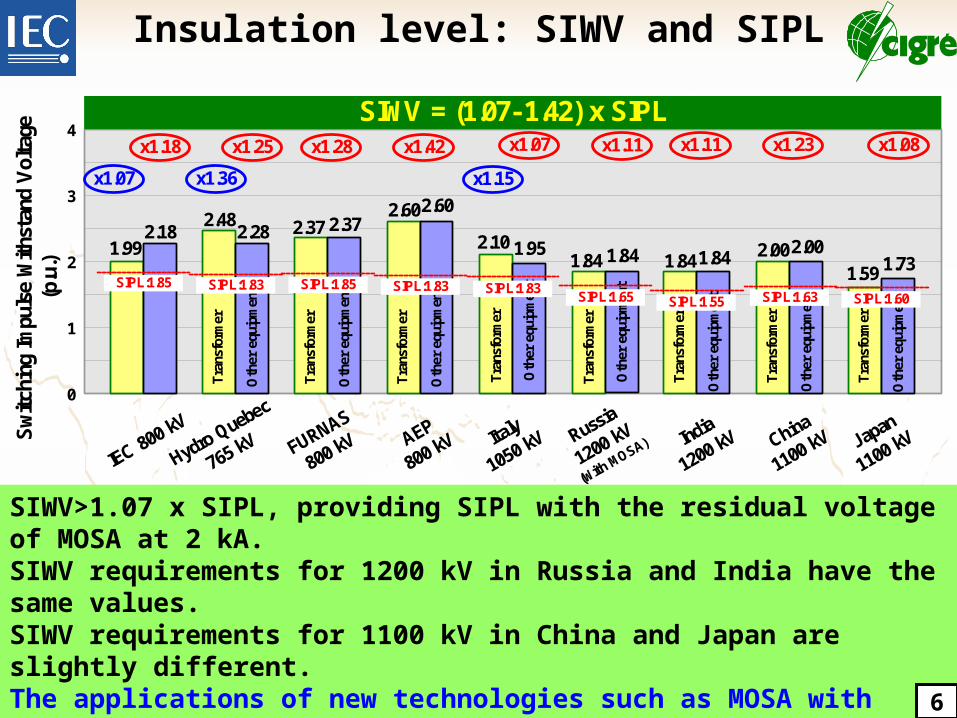
SIWV>1.07 x SIPL, providing SIPL with the residual voltage of MOSA at 2 kA. SIWV requirements for 1200 kV in Russia and India have the same values.SIWV requirements for 1100 kV in China and Japan are slightly different.The applications of new technologies such as MOSA with higher performance, CB with opening/closing resistors, DS with switching resistor can effectively suppress the switching surges, which is a predominant factor to reduce the construction cost of UHV transmission. 6
Insulation level: SIWV and SIPL
0
1
2
3
4
IEC 80
0 kV
Hydro Q
uebec
765 kV
1.992.18
FURNAS
800 kV AEP
800 kV
Switc
hing
Impu
lse
With
stan
d Vol
tage
(p
.u.)
x1.18
SIPL:1.85
2.482.28
Tra
nsfo
rmer
Oth
er e
quip
men
t
x1.25
SIPL:1.83
2.372.37
Tra
nsfo
rmer
Oth
er e
quip
men
t
x1.28
SIPL:1.85
2.602.60
Tra
nsfo
rmer
Oth
er e
quip
men
t
x1.42
SIPL:1.83
SIWV = (1.07-1.42) x SIPL
x1.07 x1.36
Russia
1200 k
V
(With MOSA)
1.841.84
Tra
nsfo
rmer
Oth
er e
quip
men
t
SIPL:1.65
x1.11
Italy
1050 k
V
2.101.95
Tra
nsfo
rmer
Oth
er e
quip
men
tSIPL:1.83
x1.07
x1.15
India
1200 k
V
1.841.84
Tra
nsfo
rmer
Oth
er e
quip
men
t
SIPL:1.55
x1.11 x1.23
China
1100 k
V
2.002.00
Tra
nsfo
rmer
Oth
er e
quip
men
tSIPL:1.63
J apan
1100 k
V
1.591.73
Tra
nsfo
rmer
Oth
er e
quip
men
tSIPL:1.60
x1.08
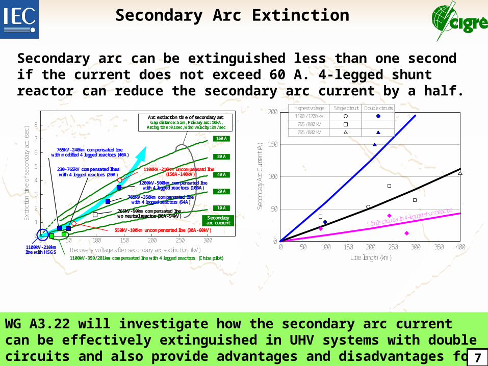
WG A3.22 will investigate how the secondary arc current can be effectively extinguished in UHV systems with double circuits and also provide advantages and disadvantages for HSGS and Four legged shunt reactor more in depth.
Secondary Arc Extinction
7
0 50 100 150 200 250 300
Recovery voltage after secondary arc extinction (kV)
Extin
ctio
n tim
e of
sec
onda
ry a
rc (se
c)
0
1
2
3
4
5
6
7
8
1100kV-210kmline with HSGS
Arc extinction time of secondary arcGap distance: 5.5m, Primary arc: 10kA,
Arcing time: 0.1sec, Wind velocity: 2m/sec
765kV-240km compensated linewith modified 4 legged reactors (40A)
230-765kV compensated lineswith 4 legged reactors (20A)
1100kV-210km uncompensatd line(150A-140kV)
1200kV-500km compensated linewith 4 legged reactors (106A)
765kV-350km compensated linewith 4 legged reactors (64A)
765kV-90km compensated linewo neutral reactor (38A-94kV)
550kV-100km uncompensated line (30A-60kV)
Secondary arc current
10 A
20 A
40 A
80 A
160 A
1100kV-359/281km compensated line with 4 legged reactors (China pilot)
0
50
100
150
200
0 50 100 150 200 250 300 350 400
Line length (km)Se
cond
ary
Arc
Curre
nt (A
)
Highest voltage Single circuit Double circuits
1100 / 1200 kV
765 / 800 kV
765 / 800 kV
Single circuit with 4-legged shunt reactor
Secondary arc can be extinguished less than one second if the current does not exceed 60 A. 4-legged shunt reactor can reduce the secondary arc current by a half.
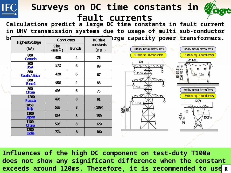
Surveys on DC time constants in fault currents
Tower and conductor designs
Calculations predict a large DC time constants in fault current in UHV transmission systems due to usage of multi sub-conductor bundles and the existence of large capacity power transformers.
16.5m
16m
15.5m
19m
72.5
m90
m10
7.5m
120m
810mm sq. -8 conductors
1100kV transmission lines
27.4
m40.3
m
15.24m
42.7m
1360mm sq. -4 conductors
800kV transmission lines
35 (5
4.5)
m22
.6 (4
2.1)
m
12m 12m
20.12m
1360mm sq. -4 conductors
800kV transmission lines
Influences of the high DC component on test-duty T100a does not show any significant difference when the constant exceeds around 120ms. Therefore, it is recommended to use a special case time constant of 120 ms for rated voltages higher than 800 kV.
ConductorsHighest voltage
( kV)Size
( mm 2 ) Bundle
DC time constants
( ms )800
Canada 686 4 75
800USA 572 6 89
800South Africa 428 6 67
800Brazil 603 4 88
800China 400 6 75
1200Russia 400 8 91
1050Italy 520 ( 100)
1100Japan 810 150
1100China 500 120
8
8
8
1200India 774 1008
8
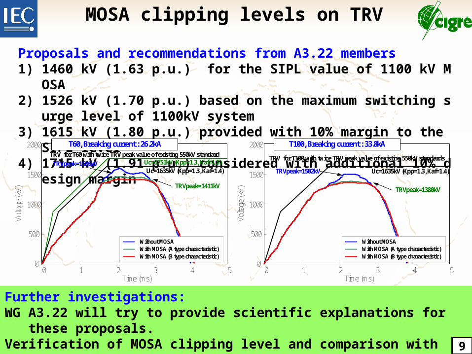
Further investigations:WG A3.22 will try to provide scientific explanations for these proposals.Verification of MOSA clipping level and comparison with the analytical TRVLong-term reliability of high-performance MOSA 9
MOSA clipping levels on TRV
Proposals and recommendations from A3.22 members1) 1460 kV (1.63 p.u.) for the SIPL value of 1100 kV MOSA2) 1526 kV (1.70 p.u.) based on the maximum switching surge level of 1100kV system3) 1615 kV (1.80 p.u.) provided with 10% margin to the SIPL level4) 1715 kV (1.91 p.u.) considered with additional 10% design margin
0 4Time (ms)
1 52 3
Uc=1635kV (Kpp=1.3, Kaf=1.4)
0
500
Volta
ge (k
V)
1000
1500
2000 T60, Breaking current : 26.2kATRV for T60 with twice TRV peak value of existing 550kV standard
Without MOSAWith MOSA (A type characteristic)With MOSA (B type characteristic)
Uc=1751kV (Kpp=1.3, Kaf=1.5)
0 4Time (ms)
1 52 30
500Vo
ltage
(kV)
1000
1500
2000 T100, Breaking current : 33.8kA
TRV for T100 with twice TRV peak value of existing 550kV standards
Without MOSAWith MOSA (A type characteristic)With MOSA (B type characteristic)
TRVpeak=1586kV
TRVpeak=1411kV
Uc=1635kV (Kpp=1.3, Kaf=1.4)TRVpeak=1502kV
TRVpeak=1380kV
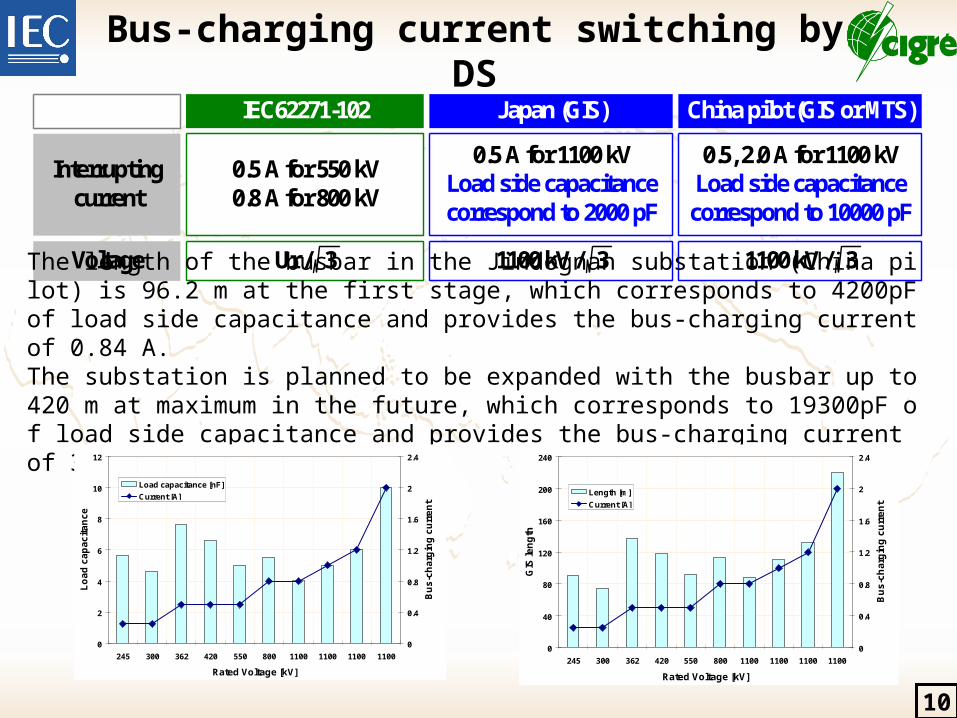
Bus-charging current switching by DS
IEC62271-102 Japan (GIS) China pilot (GIS or MTS)
0.5 A for 550 kV0.8 A for 800 kV
0.5 A for 1100 kVLoad side capacitance correspond to 2000 pF
0.5, 2.0 A for 1100 kVLoad side capacitance
correspond to 10000 pF
Interruptingcurrent
1100 kV / 3Ur / 3 1100 kV / 3Voltage
The length of the busbar in the Jindognan substation (China pilot) is 96.2 m at the first stage, which corresponds to 4200pF of load side capacitance and provides the bus-charging current of 0.84 A.The substation is planned to be expanded with the busbar up to 420 m at maximum in the future, which corresponds to 19300pF of load side capacitance and provides the bus-charging current of 3.9 A.
0
2
4
6
8
10
12
245 300 362 420 550 800 1100 1100 1100 1100
Rated Voltage [kV]
Lo
ad
ca
pa
cit
an
ce
0
0.4
0.8
1.2
1.6
2
2.4
Bu
s-c
ha
rgin
g c
urr
en
t
Load capacitance [nF]
Current [A]
0
40
80
120
160
200
240
245 300 362 420 550 800 1100 1100 1100 1100
Rated Voltage [kV]
GIS
len
gth
0
0.4
0.8
1.2
1.6
2
2.4
Bu
s-c
ha
rgin
g c
urr
en
t
Length [m]
Current [A]
10
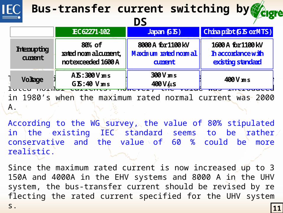
Bus-transfer current switching by DS
The existing IEC standard recommended 80-100 % of the rated normal currents. However, the value was introduced in 1980’s when the maximum rated normal current was 2000 A.
According to the WG survey, the value of 80% stipulated in the existing IEC standard seems to be rather conservative and the value of 60 % could be more realistic.
Since the maximum rated current is now increased up to 3150A and 4000A in the EHV systems and 8000 A in the UHV system, the bus-transfer current should be revised by reflecting the rated current specified for the UHV systems.
IEC62271-102 Japan (GIS) China pilot (GIS or MTS)
80% of rated normal current, not exceeded 1600 A
8000 A for 1100 kVMaximum rated normal
current
1600 A for 1100 kVIn accordance withexisting standard
Interruptingcurrent
300 V rms
400 V/sAIS: 300 V rms
GIS: 40 V rms 400 V rmsVoltage
11
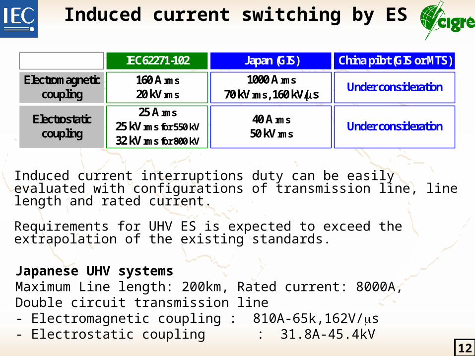
Induced current switching by ES
Induced current interruptions duty can be easily evaluated with configurations of transmission line, line length and rated current.
Requirements for UHV ES is expected to exceed the extrapolation of the existing standards.
IEC62271-102 Japan (GIS) China pilot (GIS or MTS)
160 A rms
20 kV rms 1000 A rms
70 kV rms, 160 kV/sUnder consideration
Electromagnetic coupling
40 A rms
50 kV rms
25 A rms
25 kV rms for 550 kV
32 kV rms for 800 kV
Electrostaticcoupling
Under consideration
Japanese UHV systemsMaximum Line length: 200km, Rated current: 8000A, Double circuit transmission line- Electromagnetic coupling : 810A-65k,162V/s- Electrostatic coupling : 31.8A-45.4kV
12
IEC SC17A requests for CIGRE on UHV standardizations
IEC TC17 requested CIGRE WG A3.22 to investigate the technical backgrounds of UHV substation equipment in accordance with the following IEC standards.
WG A3.22 will continuously provide technical backgrounds to support the standardization works within IEC TC17.
IEC 62271-1 Ed.1.0, HV Switchgear & Controlgear-Part 1: Common specificationsIEC 62271-100 Ed.2.0, HV Switchgear & Controlgear-Part 100: Circuit BreakerIEC 62271-101 Ed.1.0, HV Switchgear & Controlgear-Part 101: Sythetic testingIEC 62271-102 Ed.1.0, HV Switchgear & Controlgear-Part 102: A.C. DS and ESIEC 62271-110 Ed.1.0, HV Switchgear & Controlgear-Part 110: Inductive load switching
Application Guide to IEC 62271-100 and IEC 62271-1: Opening resistorNew project : High-Speed Grounding Switches
13
Summary and Considerations
Insulation levelsSuppressing switching overvoltage as much as possible is a predominant factor to reduce the height of transmission towers and the dimension of open-air parts in substations. Such technologies as MOSA with higher performance, CB with opening/closing resistors, DS with switching resistor can effectively suppress the switching surges less than 1.6pu for substation equipment and 1.7pu for OH-lines.
Secondary arc4-legged shunt reactor can reduce the secondary arc current by a half.Secondary arc can be extinguished less than 1 sec. if the current does not exceed 60 A.
First-pole-to-clear factor (FPCF)Use of a large capacity power transformer reduces FPCF (1.1 for Japan, 1.2 for India)
DC time constant / Line surge impedanceMulti sub-conductors bundles with large diameter can increase the time constants (150 ms for Japan, 120 ms for China) and reduce the line surge impedance around 350 ohm.
TRVMOSAs reduce the TRV peaks for terminal faults below the SIPL for in UHV systems.TRV for TLF appears severe RRRV only in a special case.
1429-30 January 2009, New Delhi, India