Embed Size (px)
Citation preview
Internet-facing PLCs as a Network Backdoor
Johannes Klick, Stephan Lau, Daniel Marzin, Jan-Ole Malchow, Volker RothFreie Universitat Berlin - Secure Identity Research Group
<firstname>.<lastname>@fu-berlin.de
Abstract—Industrial control systems (ICS) are integral com-ponents of production and control processes. Our modern infras-tructure heavily relies on them. Unfortunately, from a securityperspective, thousands of PLCs are deployed in an Internet-facingfashion. Security features are largely absent in PLCs. If they arepresent then they are often ignored or disabled because securityis often at odds with operations. As a consequence, it is oftenpossible to load arbitrary code onto an Internet-facing PLC.Besides being a grave problem in its own right, it is possible toleverage PLCs as network gateways into production networksand perhaps even the corporate IT network. In this paper,we analyze and discuss this threat vector and we demonstratethat exploiting it is feasible. For demonstration purposes, wedeveloped a prototypical port scanner and a SOCKS proxythat runs in a PLC. The scanner and proxy are written in thePLC’s native programming language, the Statement List (STL).Our implementation yields insights into what kinds of actionsadversaries can perform easily and which actions are not easilyimplemented on a PLC.
I . I N T R O D U C T I O N
Industrial control systems (ICS) are integral componentsof production and control tasks. Modern infrastructure heavilyrelies on them. The introduction of the Smart Manufacturing(Industry 4.0) technology stack further increases the dependencyon industrial control systems [1]. Modern infrastructure isalready under attack and offers a broad attack surface, rangingfrom simple XSS vulnerabilities [2], [3] to major design flawsin protocols [4], [5].
The canonical example of an attack on an industrial controlsystem is the infamous Stuxnet worm that targeted an Iranianuranium enrichment facility. However, adversaries increasinglytarget ordinary production systems [6]. A recent example is theforced shutdown of a blast furnace in a German steelworks in2014. The attackers reportedly gained access to the pertinentcontrol systems via the steelwork’s business network [7]. Thisis a typical attack vector because business networks servehumans and humans are susceptible to spear phishing.
Arguably, spear phishing is easy to carry out when ac-companied with research and social engineering. However,in far too many cases, even easier ways exist into industrialcontrol systems. Published scan data shows that thousands ofICS components, for example, programmable logic controllers(PLCs), are directly reachable from the Internet [8], [9], [10].While only one PLC of a production facility may be reachablein this fashion, the PLC may connect to internal networks withmany more PLCs. This is what we call the “deep” industrialnetwork. In this paper, we investigate how adversaries canleverage exposed PLCs to extend their access from the Internetto the deep industrial network.
The approach we take is to turn PLCs into gateways (wefocus on Siemens PLCs). This is enabled by a notorious lackof proper means of authentication in PLCs. A knowledgeableadversary with access to a PLC can download and upload codeto it, as long as the code consists of MC7 bytecode, which is thenative form of PLC code. We explored the runtime environmentof PLCs and found that it is possible to implement severalnetwork services using uploaded MC7 code. In particular, weimplemented
• a SNMP scanner for Siemens PLCs, and
• a fully fledged SOCKS proxy for Siemens PLCs
entirely in Statement List (STL), which compiles to MC7byte code. Our scanner and proxy can be deployed on aPLC without service interruption to the original PLC program,which makes it unlikely that unsuspecting operators will noticethe infection. In order to demonstrate and analyze deepindustrial network intrusion, we developed a proof of concepttool called PLCinject. Based on our proof of concept, weanalyzed whether the augmentation of the original code withour PLC malware led to measurable effects that might helpdetecting such augmentations. We looked at timing effects,specifically. We found that augmented code is distinguishablefrom unaugmented code, that is, statistically significant timingdifferences exist. The difference is minor in absolute terms,that is, the augmentation does not likely affect a productionprocess and hence it will not be noticable unless networkoperators actively monitor for malicious access. The downsideis that operators of industrial networks must include PLCsin their vulnerability assessment procedures and they mustactively monitor internal networks for malicious network trafficthat originates from their own PLCs. Moreover, adversariescan leverage our approach to attack a company’s businessnetwork from the industrial network. This means that networkadministrators must guard their business networks from thefront and the back. The remainder of this paper is organized asfollows. We begin with a discussion of work related to ours in§II. In §III, we give technical background for readers unfamiliarwth industrial control systems. We describe our attack andintrusion methods in §IV. In §VI, we discuss mitigations and§VII concludes the paper.
I I . R E L AT E D W O R K
Various attacks on PLCs have been published. Most attackstarget the operating systems of PLCs. In contrast we leveragethe abilities of logic programs running on the PLCs. As suchwe do not use any unintended functionality. In the following,we compare our approach to well-known (code) releases andpublished attacks that manipulate logic code. One of the most
ERP
MES
SCADA
PLC
In-/Outputsignals
Plan
ning
Dat
aga
ther
ing
Manufacturing process
Figure 1: Automation pyramid, adopted from [15]
cited SCADA attack descriptions is Beresfords’ 2011 BlackHat USA release [5]. He demonstrated how credentials canbe extracted from remote memory dumps. In addition heshows how to start and stop PLCs through replay attacks.In contrast to our work he does not alter the logic programon the PLC. In 2011 Langner released “A timebomb withfourteen bytes” [11] wherein he describes how to inject roguelogic code into PLCs. He borrows the same code prependingtechnology as we do, from Stuxnet. He conceptualizes howto take control away from the original code. In contrast, ourprogram runs in parallel to the original code with the goal to notinterfere with the original code’s execution. An attack similarto Langners’ was presented at Black Hat USA 2013 by Meixelland Forner [12]. In their release they describe different waysof exploiting PLCs. Among those are ways to remove safetychecks from logic code. Again, our approach differs as we addnew functionality while preserving original functionality. Toour best knowledge, the first academic paper on PLC malwarewas published by McLaughlin in 2011 [13]. In this work heproposes a basic mechanism for dynamic payload generation.He presents an approach based on symbolic execution thatrecovers boolean logic from PLC logic code. From this, hetries to determine unsafe states for the PLC and generates codeto trigger one of these states. In 2012 McLaughlin publisheda followup paper [14], which extends his approach in a waythat automatically maps the code to a predefined model bymeans of model checking. With his model, he can specify adesired behaviour and automatically generate attack code. Inhis work McLaughlin focuses on manipulating the control flowof a PLC. We, in contrast, use the PLC as a gateway to thenetwork and leave its original functions untouched.
I I I . I N D U S T R I A L C O N T R O L S Y S T E M S
Figure 1 illustrates the structure of a typical company thatuses automation systems. Industrial control systems consistof several layers. At the top are enterprise resource planning(ERP) systems, which hold the data about currently availableresources and production capacities. Manufacturing executionsystems (MES) are able to manage multiple factories or plantsand receives tasks from ERP systems. The systems below theMES are located in the factory. Supervision, control and dataacquisition (SCADA) systems control production lines. They
� &\FOH�DQG�UHDFWLRQ�WLPHV�� ����&\FOH�WLPH�
&38���[&�DQG�&38���[��7HFKQLFDO�GDWD�0DQXDO��(GLWLRQ����������$�(������������ ����
6HTXHQFH�RI�F\FOLF�SURJUDP�SURFHVVLQJ�7KH�WDEOH�DQG�ILJXUH�EHORZ�VKRZ�WKH�SKDVHV�LQ�F\FOLF�SURJUDP�SURFHVVLQJ��
7DEOH����� &\FOLF�SURJUDP�SURFHVVLQJ�
6WHS� 6HTXHQFH��� 7KH�RSHUDWLQJ�V\VWHP�LQLWLDWHV�F\FOH�WLPH�PRQLWRULQJ���� 7KH�&38�FRSLHV�WKH�YDOXHV�RI�WKH�SURFHVV�LPDJH�RI�RXWSXWV�WR�WKH�RXWSXW�PRGXOHV����� 7KH�&38�UHDGV�WKH�VWDWXV�DW�WKH�LQSXWV�RI�WKH�LQSXW�PRGXOHV�DQG�WKHQ�XSGDWHV�WKH�
SURFHVV�LPDJH�RI�LQSXWV���� 7KH�&38�SURFHVVHV�WKH�XVHU�SURJUDP�LQ�WLPH�VKDUHV�DQG�H[HFXWHV�SURJUDP�LQVWUXFWLRQV���� $W�WKH�HQG�RI�D�F\FOH��WKH�RSHUDWLQJ�V\VWHP�H[HFXWHV�TXHXHG�WDVNV��IRU�H[DPSOH��ORDGLQJ�
DQG�GHOHWLQJ�EORFNV���� 7KH�&38�WKHQ�UHWXUQV�WR�WKH�VWDUW�RI�WKH�F\FOH��DQG�UHVWDUWV�F\FOH�WLPH�PRQLWRULQJ��
Cyc
le t
ime
Time slices (1 ms each)
Time slice (1 ms)
2
3
4
5
�,Q�FRQWUDVW�WR�6������&38V��WKH�6������&38V�GDWD�RQO\�DOORZ�GDWD�DFFHVV�IURP�DQ�23���73��PRQLWRU�DQG�PRGLI\�IXQFWLRQV��DW�WKH�VFDQ�F\FOH�FKHFN�SRLQW��'DWD�FRQVLVWHQF\��VHH�WKH�7HFKQLFDO�'DWD���3URFHVVLQJ�RI�WKH�XVHU�SURJUDP�LV�QRW�LQWHUUXSWHG�E\�WKH�PRQLWRU�DQG�PRGLI\�IXQFWLRQV��
Downloaded from www.Manualslib.com manuals search engine
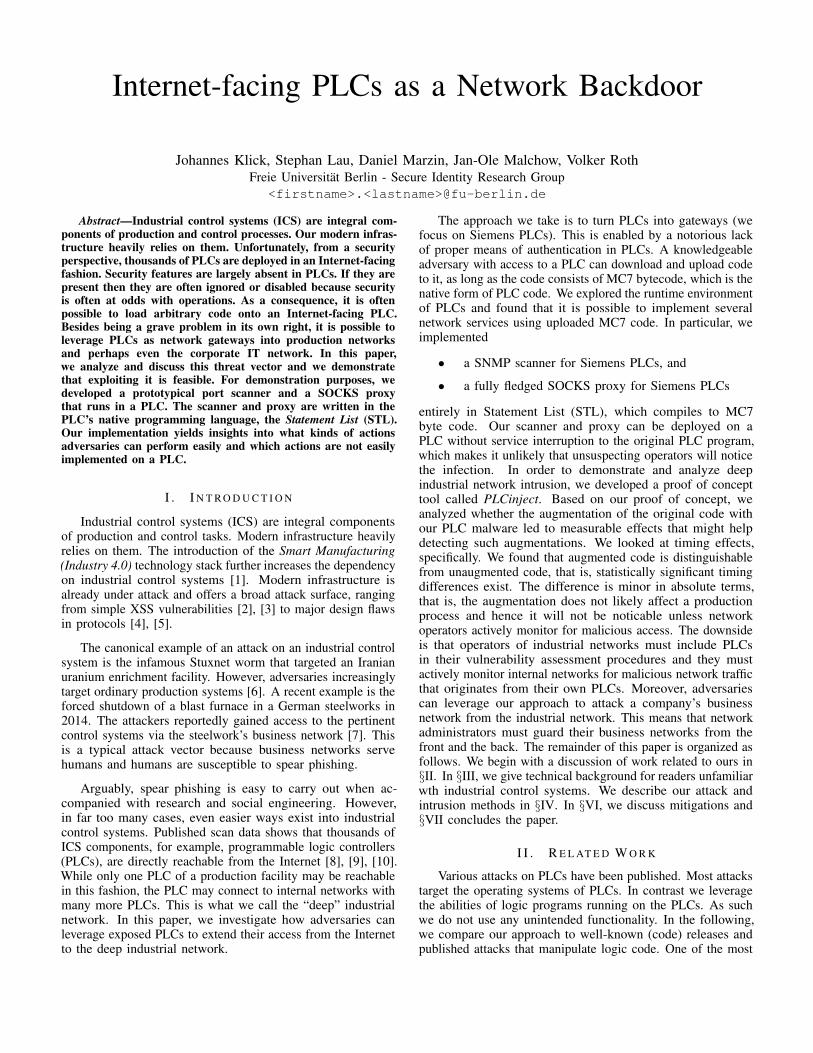
Figure 2: Overview of program execution, extracted from [17]
provide data about the current production state and they providemeans for intervention. The devices holding the logic forproduction processes are called programmable logic controllers(PLC). We explain them in more detail in section III-A. Humanmachine interfaces (HMI) display the current progress and allowoperators to interact with the production process.
A. PLC Hardware
A PLC consists of a central processing unit (CPU) which isattached to a number of digital and analog inputs and outputs. APLC program stored on the integrated memory or on a externalMulti Media Card (MMC) defines how the inputs and outputsare controlled. A special feature of a PLC is the guaranty of adefined executions time to control time critical processes. Forcommunication or special purpose applications the functionalityof a CPU can be extended with modules. The Siemens S7-314C-2 PN/DP we use in our experiments has 24 digital inputs,16 digital outputs, 5 analog inputs, 2 analog outputs and aMMC slot. It is equipped with 192KByte of internal memory,64KByte can be used for permanent storage. Additionally, thePLC has one RS485 and two RJ45 sockets [16].
B. PLC Execution Environment
Siemens PLCs run a real time operating system (OS), whichinitiates the cycle time monitoring. Afterwards the OS cyclesthrough four steps (see figure 2). In the first step the CPUcopies the values of the process image of outputs to the outputmodules. In the second step the CPU reads the status of theinput modules and updates the process image of input values.In the third step the user program is executed in time sliceswith a duration of 1 ms. Each time slice is divided into threeparts, which are executed sequentially: The operating system,the user program and the communication. The number of timeslices depends on the current user program. By default the timeshould be not longer than 150 ms. An engineer can configure adifferent value. If the defined time expires, an interrupt routineis called. In the common case the CPU returns to the start ofthe cycle and restarts the cycle time monitoring [17].
C. Software
Siemens provides their Total Integrated Automation (TIA)portal software to engineers for the purpose of developingPLC programs. It consists of two main components. TheSTEP7 as development environment for PLCs and WinCC toconfigure HMIs. Engineers are able to program PLC in LadderDiagram (LAD), Function Block Diagram (FBD), structuredcontrol language (SCL) and Statement List (STL). In contrastto the text-based SCL and assembler-like STL the LAD andFBD languages are graphical. PLC programs are divided intounits of organization blocks (OB), functions (FC), functionblocks (FB), data blocks (DB), system functions (SFC), systemfunction blocks (SFB) and system data blocks (SDB). OBs,FCs and FBs contain the actual code while DBs provide storagefor data structures and SDBs current PLC configurations. Forinternal data storage addressing the prefix M for memory isused.
D. PLC Programs
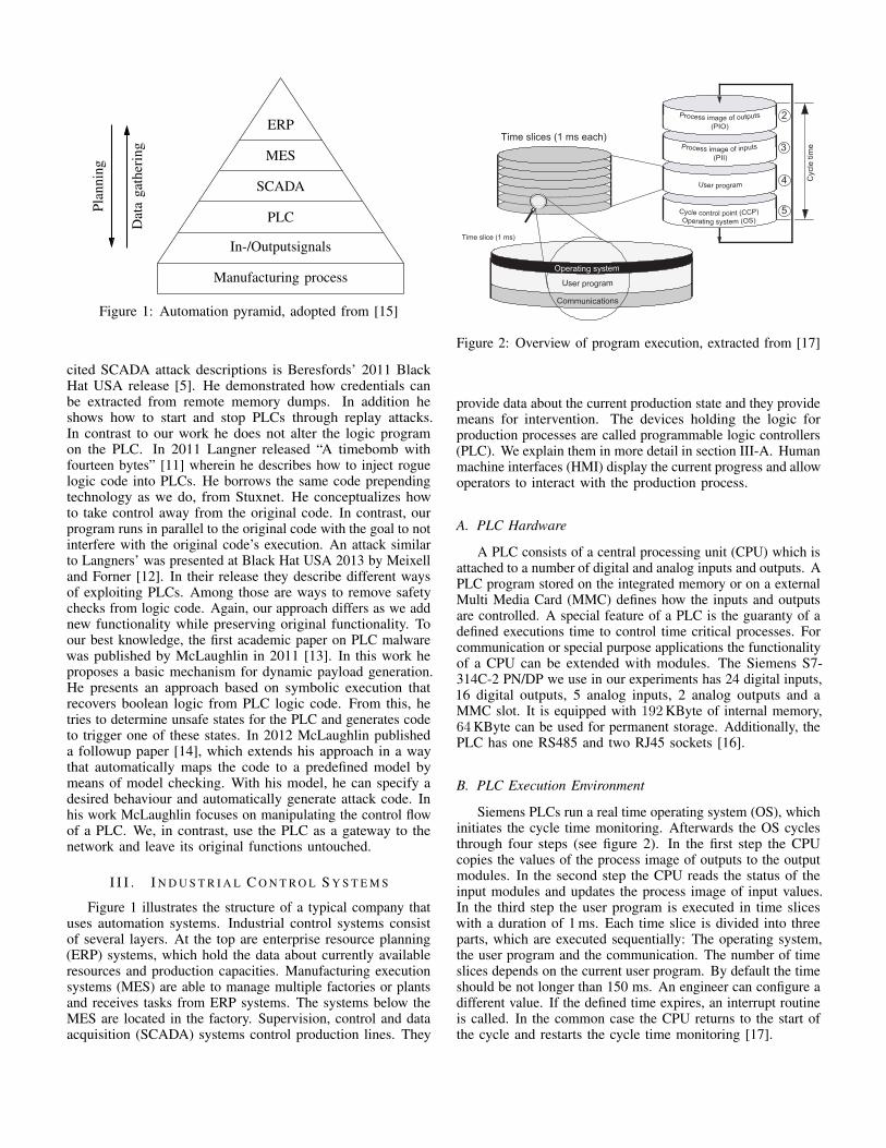
A PLC program consists of at least one organization blockcalled OB1, which is comparable to the main function in atraditional C program. It will be called by the operating system.There exist more organization blocks for special purposes, forexample, OB100. This block is called once when the PLCstarts and is used usually for the initialization of the system.Engineers can encapsulate code by using functions and functionblocks. The only difference is an additional DB as a parameterto calling a FB. The SFCs and SFBs are built into the PLC. Thecode can not be inspected. The STEP7 software knows whichSFCs and SFBs are available based on hardware configurationsteps. The following examples give an overview of the theprogramming languages SCL, LAD and STL. Each exampleshows the same configuration of three inputs and one output.First, the CPU performs a logical AND operation of inputs0.0 and 0.1. Next, it calculates a logical OR operation ofthe outcome and the input 0.2. The result is written to output0.0 which sets the logical values to the connected wire inthe next cycle. The first example represents the describedprogram in STL. This is done in four lines of assembler-likeinstructions. Each line defines one instruction.
1 A %I0 . 02 A %I0 . 13 O %I0 . 24 = %Q0 . 0
The next example shows the same program in the text-basedlanguage SCL. This program can be expressed in one line.
1 %Q0 . 0 := (% I0 . 0 AND %I0 . 1 ) OR %I0 . 2 ;
The graphical example needs the help of the STEP7. Inputsand outputs are positioned through drag & drop on the wire.New connections can be made on predefined positions byselecting the wire-tool from the toolbar above. Figure 3 showsthe graphical representation of our example program.
The following description can also be found in the Siemensmanual delivered with the PLC [18]. The CPU has severalregisters used for execution and current state. For binary
%I 0.0 %I 0.1
%I 0.2
%Q 0.0
Figure 3: Function block diagram example
operations the status word register is important. All binaryoperations influence this register. The CPU uses for calculationsup to four accumulator registers of 32 bits width. They areorganized like a stack. It is possible to address independentlyeach byte of the top register. Before a new value is loadedinto the accumulator one the current value is copied toaccumulator two. For adding two numbers the values haveto be loaded successively into the accumulator register beforethe +D operation is called. The result is written back intoaccumulator one. In STL the program would look like asfollowing.
1 L DW#16#1 / / ACCU1=12 L DW#16#2 / / ACCU1=2 ,ACCU2=13 +D / / ACCU1=ACCU1+ACCU2
Code which is used multiple times in the program shouldbe implemented as functions. These functions can be calledfrom every point in the code. The CALL instruction allows tojump into the defined function. The necessary parameters aredefined in the called function header and have to be specifiedbelow every CALL instruction.
1 CALL FC12 VAR1 := 13 VAR2 := W#16#A
As mentioned earlier the only difference between functionblocks and functions is a reference to the corresponding datablock. In many cases the program needs storage which isassigned to a specific function to read constants or save processvalues. It is unusual to put constants direct in the code,because the code have to be recompiled after every change. Incontrast data blocks can be manipulated easily even remotely.A function block call looks like as following.
1 CALL FB1 , %DB12 VAR1 := 13 VAR2 := W#16#A
Both function types can define different parameters: IN, OUT,IN_OUT, TEMP and RET_VAL. The FB STAT parametersare stored in its data block, which is passed as an additionalargument. The TEMP type declares local variables whichonly are available in the function. The other types are selfexplanatory.
E. Binary Representation of PLC Program
Every code written in any language is compiled into MC7.The opcode length of MC7 instructions is variable and theencoding of parameters differs on many instructions. The
binary representation of the example program from the sectionbefore looks as following.
1 00100000 A %I0 . 02 00110000 A %I0 . 13 01120000 O %I0 . 24 41100000 = %Q0 . 0
F. Network Protocol
The Siemens PLCs uses the proprietary S7Comm protocolfor transferring blocks. It is a remote procedure call (RPC)protocol based on TCP/IP and ISO over TCP. Figure 4illustrates the encapsulation of the protocols. The protocolprovides the following functionality:
• System State List (SSL) request• List available blocks• Read/write data• Block info request• Up-/download block• Transfer block into filesystem• Start, stop and memory reset• Debugging
The executing of one of these function requires an initializedconnection. After a regular TCP handshake the ISO over TCPsetup is proceeded to negotiate the PDU size. In the S7Commprotocol the client has to provide additionally to his preferredPDU size the rack and slot of the CPU (see connection setup infigure 5). The CPU responses with its preferred PDU size andboth agree to continue with the minimum of both values. Afterthis initialization the client is able to invoke the functions onthe CPU. Figure 5 shows the packet order of a download blockfunction including the transfer into the filesystem. The PLCcontrols the download process after receiving the downloadrequest. The number of download block requests dependson the length of the block and the PDU size. The end issignaled with the download end request. The PLC waits afterreceiving the acknowledgement for further requests. Finallythe transferred block should be persisted by calling the plccontrol request. With the destination filesystem P as parameterthe CPU stores the block and executes it.
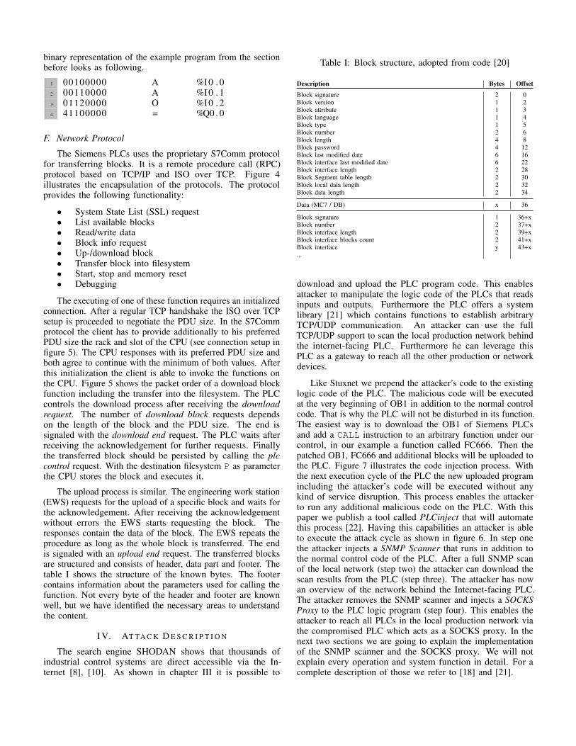
The upload process is similar. The engineering work station(EWS) requests for the upload of a specific block and waits forthe acknowledgement. After receiving the acknowledgementwithout errors the EWS starts requesting the block. Theresponses contain the data of the block. The EWS repeats theprocedure as long as the whole block is transferred. The endis signaled with an upload end request. The transferred blocksare structured and consists of header, data part and footer. Thetable I shows the structure of the known bytes. The footercontains information about the parameters used for calling thefunction. Not every byte of the header and footer are knownwell, but we have identified the necessary areas to understandthe content.
I V. AT TA C K D E S C R I P T I O N
The search engine SHODAN shows that thousands ofindustrial control systems are direct accessible via the In-ternet [8], [10]. As shown in chapter III it is possible to
Table I: Block structure, adopted from code [20]
Description Bytes Offset
Block signature 2 0Block version 1 2Block attribute 1 3Block language 1 4Block type 1 5Block number 2 6Block length 4 8Block password 4 12Block last modified date 6 16Block interface last modified date 6 22Block interface length 2 28Block Segment table length 2 30Block local data length 2 32Block data length 2 34
Data (MC7 / DB) x 36
Block signature 1 36+xBlock number 2 37+xBlock interface length 2 39+xBlock interface blocks count 2 41+xBlock interface y 43+x...
download and upload the PLC program code. This enablesattacker to manipulate the logic code of the PLCs that readsinputs and outputs. Furthermore the PLC offers a systemlibrary [21] which contains functions to establish arbitraryTCP/UDP communication. An attacker can use the fullTCP/UDP support to scan the local production network behindthe internet-facing PLC. Furthermore he can leverage thisPLC as a gateway to reach all the other production or networkdevices.
Like Stuxnet we prepend the attacker’s code to the existinglogic code of the PLC. The malicious code will be executedat the very beginning of OB1 in addition to the normal controlcode. That is why the PLC will not be disturbed in its function.The easiest way is to download the OB1 of Siemens PLCsand add a CALL instruction to an arbitrary function under ourcontrol, in our example a function called FC666. Then thepatched OB1, FC666 and additional blocks will be uploaded tothe PLC. Figure 7 illustrates the code injection process. Withthe next execution cycle of the PLC the new uploaded programincluding the attacker’s code will be executed without anykind of service disruption. This process enables the attackerto run any additional malicious code on the PLC. With thispaper we publish a tool called PLCinject that will automatethis process [22]. Having this capabilities an attacker is ableto execute the attack cycle as shown in figure 6. In step onethe attacker injects a SNMP Scanner that runs in addition tothe normal control code of the PLC. After a full SNMP scanof the local network (step two) the attacker can download thescan results from the PLC (step three). The attacker has nowan overview of the network behind the Internet-facing PLC.The attacker removes the SNMP scanner and injects a SOCKSProxy to the PLC logic program (step four). This enables theattacker to reach all PLCs in the local production network viathe compromised PLC which acts as a SOCKS proxy. In thenext two sections we are going to explain the implementationof the SNMP scanner and the SOCKS proxy. We will notexplain every operation and system function in detail. For acomplete description of those we refer to [18] and [21].
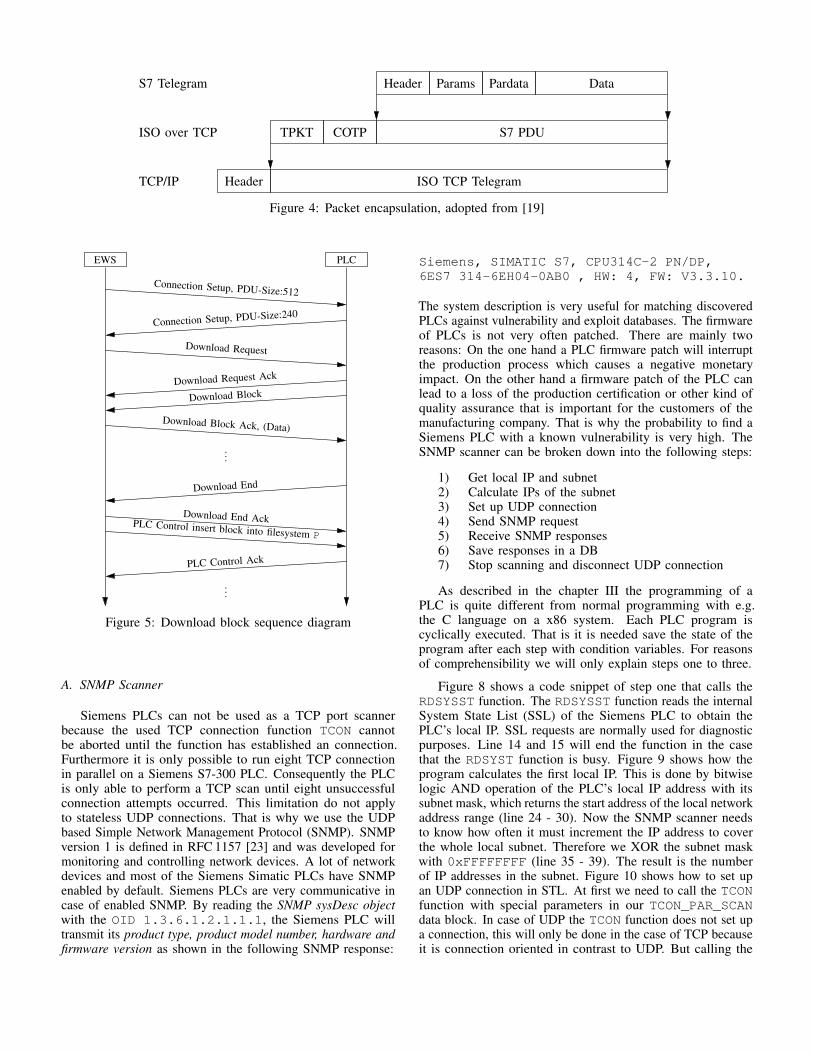
Header Params Pardata DataS7 Telegram
S7 PDUCOTPTPKTISO over TCP
ISO TCP TelegramHeaderTCP/IP
Figure 4: Packet encapsulation, adopted from [19]
EWS PLC
Connection Setup, PDU-Size:512
Connection Setup, PDU-Size:240
Download Request
Download Request Ack
Download Block
Download Block Ack, (Data)
...
Download End
Download End AckPLC Control insert block into filesystem P
PLC Control Ack
...
Figure 5: Download block sequence diagram
A. SNMP Scanner
Siemens PLCs can not be used as a TCP port scannerbecause the used TCP connection function TCON cannotbe aborted until the function has established an connection.Furthermore it is only possible to run eight TCP connectionin parallel on a Siemens S7-300 PLC. Consequently the PLCis only able to perform a TCP scan until eight unsuccessfulconnection attempts occurred. This limitation do not applyto stateless UDP connections. That is why we use the UDPbased Simple Network Management Protocol (SNMP). SNMPversion 1 is defined in RFC 1157 [23] and was developed formonitoring and controlling network devices. A lot of networkdevices and most of the Siemens Simatic PLCs have SNMPenabled by default. Siemens PLCs are very communicative incase of enabled SNMP. By reading the SNMP sysDesc objectwith the OID 1.3.6.1.2.1.1.1, the Siemens PLC willtransmit its product type, product model number, hardware andfirmware version as shown in the following SNMP response:
Siemens, SIMATIC S7, CPU314C-2 PN/DP,6ES7 314-6EH04-0AB0 , HW: 4, FW: V3.3.10.
The system description is very useful for matching discoveredPLCs against vulnerability and exploit databases. The firmwareof PLCs is not very often patched. There are mainly tworeasons: On the one hand a PLC firmware patch will interruptthe production process which causes a negative monetaryimpact. On the other hand a firmware patch of the PLC canlead to a loss of the production certification or other kind ofquality assurance that is important for the customers of themanufacturing company. That is why the probability to find aSiemens PLC with a known vulnerability is very high. TheSNMP scanner can be broken down into the following steps:
1) Get local IP and subnet2) Calculate IPs of the subnet3) Set up UDP connection4) Send SNMP request5) Receive SNMP responses6) Save responses in a DB7) Stop scanning and disconnect UDP connection
As described in the chapter III the programming of aPLC is quite different from normal programming with e.g.the C language on a x86 system. Each PLC program iscyclically executed. That is it is needed save the state of theprogram after each step with condition variables. For reasonsof comprehensibility we will only explain steps one to three.
Figure 8 shows a code snippet of step one that calls theRDSYSST function. The RDSYSST function reads the internalSystem State List (SSL) of the Siemens PLC to obtain thePLC’s local IP. SSL requests are normally used for diagnosticpurposes. Line 14 and 15 will end the function in the casethat the RDSYST function is busy. Figure 9 shows how theprogram calculates the first local IP. This is done by bitwiselogic AND operation of the PLC’s local IP address with itssubnet mask, which returns the start address of the local networkaddress range (line 24 - 30). Now the SNMP scanner needsto know how often it must increment the IP address to coverthe whole local subnet. Therefore we XOR the subnet maskwith 0xFFFFFFFF (line 35 - 39). The result is the numberof IP addresses in the subnet. Figure 10 shows how to set upan UDP connection in STL. At first we need to call the TCONfunction with special parameters in our TCON_PAR_SCANdata block. In case of UDP the TCON function does not set upa connection, this will only be done in the case of TCP becauseit is connection oriented in contrast to UDP. But calling the
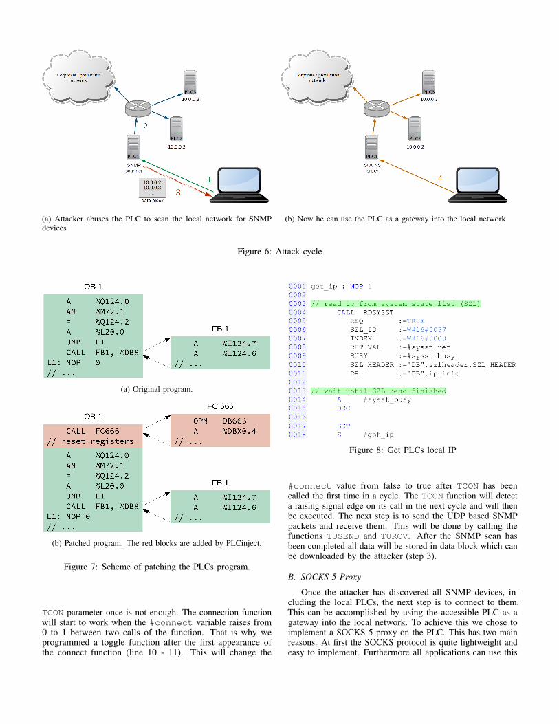
(a) Attacker abuses the PLC to scan the local network for SNMPdevices
(b) Now he can use the PLC as a gateway into the local network
Figure 6: Attack cycle
(a) Original program.
(b) Patched program. The red blocks are added by PLCinject.
Figure 7: Scheme of patching the PLCs program.
TCON parameter once is not enough. The connection functionwill start to work when the #connect variable raises from0 to 1 between two calls of the function. That is why weprogrammed a toggle function after the first appearance ofthe connect function (line 10 - 11). This will change the
Figure 8: Get PLCs local IP
#connect value from false to true after TCON has beencalled the first time in a cycle. The TCON function will detecta raising signal edge on its call in the next cycle and will thenbe executed. The next step is to send the UDP based SNMPpackets and receive them. This will be done by calling thefunctions TUSEND and TURCV. After the SNMP scan hasbeen completed all data will be stored in data block which canbe downloaded by the attacker (step 3).
B. SOCKS 5 Proxy
Once the attacker has discovered all SNMP devices, in-cluding the local PLCs, the next step is to connect to them.This can be accomplished by using the accessible PLC as agateway into the local network. To achieve this we chose toimplement a SOCKS 5 proxy on the PLC. This has two mainreasons. At first the SOCKS protocol is quite lightweight andeasy to implement. Furthermore all applications can use this
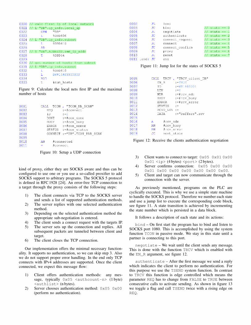
Figure 9: Calculate the local nets first IP and the maximalnumber of hosts
Figure 10: Setup a UDP connection
kind of proxy, either they are SOCKS aware and thus can beconfigured to use one or you use a so-called proxifier to addSOCKS support to arbitrary programs. The SOCKS 5 protocolis defined in RFC 1928 [24]. An error-free TCP connection toa target through the proxy consists of the following steps:
1) The client connects via TCP to the SOCKS serverand sends a list of supported authentication methods.
2) The server replies with one selected authenticationmethod.
3) Depending on the selected authentication method theappropriate sub-negotiation is entered.
4) The client sends a connect request with the targets IP.5) The server sets up the connection and replies. All
subsequent packets are tunneled between client andtarget.
6) The client closes the TCP connection.
Our implementation offers the minimal necessary function-ality. It supports no authentication, so we can skip step 3. Alsowe do not support proper error handling. In the end only TCPconnects with IPv4 addresses are supported. Once the clientconnected, we expect this message flow:
1) Client offers authentication methods: any mes-sage, typically 0x05 <authcount-n> (1 byte)<authlist> (n bytes).
2) Server chooses authentication method: 0x05 0x00(perform no authentication).
Figure 11: Jump list for the states of SOCKS 5
Figure 12: Receive the clients authentication negotiation
3) Client wants to connect to target: 0x05 0x01 0x000x01 <ip> (4 bytes) <port> (2 bytes).
4) Server confirms connection: 0x05 0x00 0x000x01 0x00 0x00 0x00 0x00 0x00 0x00.
5) Client and target can now communicate through theconnection with the server.
As previously mentioned, programs on the PLC arecyclically executed. This is why we use a simple state machineto handle the SOCKS protocol. Therefore we number each stateand use a jump list to execute the corresponding code block,see figure 11. A state transition is achieved by incrementingthe state number which is persisted in a data block.
It follows a description of each state and its actions:
bind – On first start the program has to bind and listen toSOCKS port 1080. This is accomplished by using the systemfunction TCON in passive mode. We stay in this state until apartner is connecting to this port.
negotiate – We wait until the client sends any message.This is done with the function TRCV which is enabled withthe EN_R argument, see figure 12.
authenticate – After the first message we send a replywhich indicates the client to perform no authentication. Forthis purpose we use the TSEND system function. In contrastto TRCV this function is edge controlled which means theparameter REQ has to change from FALSE to TRUE betweenconsecutive calls to activate sending. As shown in figure 13we toggle a flag and call TSEND twice with a rising edge onREQ.
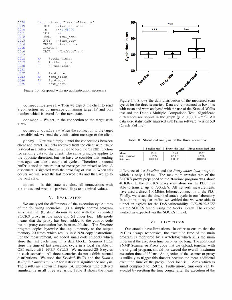
Figure 13: Respond with no authentication necessary
connect_request – Then we expect the client to senda connection set up message containing target IP and portnumber which is stored for the next state.
connect – We set up the connection to the target withTCON.
connect_confirm – When the connection to the targetis established, we send the confirmation message to the client.
proxy – Now we simply tunnel the connections betweenclient and target. All data received from the client with TRCVis stored in a buffer which is reused to feed the TSEND functionfor sending data to the client. The same principle applies tothe opposite direction, but we have to consider that sendingmessages can take a couple of cycles. Therefore a secondbuffer is used to ensure that no messages are mixed or lost. Adisconnect is signaled with the error flag of TRCV. When thisoccurs we will send the last received data and then we go tothe next state.
reset – In this state we close all connections withTDISCON and reset all persisted flags to its initial values.
V. E VA L U AT I O N
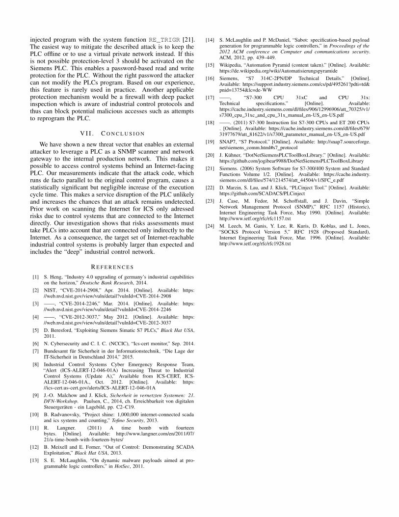
We analyzed the differences of the execution cycle timesof the following scenarios: (a) a simple control programas a baseline, (b) its malicious version with the prependedSOCKS proxy in idle mode and (c) under load. Idle modemeans that the proxy has been added to the control codebut no proxy connection has been established. The Baselineprogram copies bytewise the input memory to the outputmemory 20 times which results in 81920 copy instructions.For the measurement, we added small code snippets whichstore the last cycle time in a data block. Siemens PLCsstore the time of last execution cycle in a local variable ofOB1 called OB1_PREV_CYCLE. We measured 2046 cyclesin each scenario. All three scenarios do not exhibit normaldistributions. We used the Kruskal–Wallis and the Dunn’sMultiple Comparison Test for statistical significance analysis.The results are shown in Figure 14. Execution time differedsignificantly in all three scenarios. Table II shows the mean
Figure 14: Shows the data distribution of the measured scancycles for the three scenarios. Data are represented as boxplotswith mean and were analyzed with the use of the Kruskal-Wallistest and the Dunn’s Multiple Comparison Test. Significantdifferences are shown in the graph (p < 0.0001 =∗∗∗). Alldata were statistically analyzed with Prism software, version 5.0(Graph Pad Inc).
Table II: Statistical analysis of the three scenarios
Baseline (ms) Proxy idle (ms) Proxy under load (ms)
Mean 85.32 85.40 86.67Sdt. Deviation 0.4927 0.5003 0.5239Sdt. Error 0.01089 0.01106 0.01158
difference of the Baseline and the Proxy under load program,which is only 1.35 ms. The maximum transfer rate of theSOCKS proxy prepended to the Baseline program was about40 KB/s. If the SOCKS proxy runs alone on the PLC it isable to transfer up to 730 KB/s. All network measurementshave used a direct 100 Mbit/s Ethernet connection to the PLC.Finally, we tested the described attack cycle in our laboratory.In addition to regular traffic, we verified that we were able totunnel an exploit for the DoS vulnerability CVE-2015-2177via the SOCKS tunnel using the tsocks library. The exploitworked as expected via the SOCKS tunnel.
V I . D I S C U S S I O N
Our attacks have limitations. In order to ensure that thePLC is always responsive, the execution time of the mainprogram is monitored by a watchdog which kills the mainprogram if the execution time becomes too long. The additionalSNMP Scanner or Proxy code that we upload, together withthe original program, should not exceed the overall maximumexecution time of 150 ms. An injection of the scanner or proxyis unlikely to trigger this timeout because the mean additionalexecution time of the proxy under load is 1.35 ms which issmall compared to 150 ms. Furthermore, time-outs can beavoided by resetting the time counter after the execution of the
injected program with the system function RE_TRIGR [21].The easiest way to mitigate the described attack is to keep thePLC offline or to use a virtual private network instead. If thisis not possible protection-level 3 should be activated on theSiemens PLC. This enables a password-based read and writeprotection for the PLC. Without the right password the attackercan not modify the PLCs program. Based on our experience,this feature is rarely used in practice. Another applicableprotection mechanism would be a firewall with deep packetinspection which is aware of industrial control protocols andthus can block potential malicious accesses such as attemptsto reprogram the PLC.
V I I . C O N C L U S I O N
We have shown a new threat vector that enables an externalattacker to leverage a PLC as a SNMP scanner and networkgateway to the internal production network. This makes itpossible to access control systems behind an Internet-facingPLC. Our measurements indicate that the attack code, whichruns de facto parallel to the original control program, causes astatistically significant but negligible increase of the executioncycle time. This makes a service disruption of the PLC unlikelyand increases the chances that an attack remains undetected.Prior work on scanning the Internet for ICS only adressedrisks due to control systems that are connected to the Internetdirectly. Our investigation shows that risks assessments musttake PLCs into account that are connected only indirectly to theInternet. As a consequence, the target set of Internet-reachableindustrial control systems is probably larger than expected andincludes the “deep” industrial control network.
R E F E R E N C E S
[1] S. Heng, “Industry 4.0 upgrading of germany’s industrial capabilitieson the horizon,” Deutsche Bank Research, 2014.
[2] NIST, “CVE-2014-2908,” Apr. 2014. [Online]. Available: https://web.nvd.nist.gov/view/vuln/detail?vulnId=CVE-2014-2908
[3] ——, “CVE-2014-2246,” Mar. 2014. [Online]. Available: https://web.nvd.nist.gov/view/vuln/detail?vulnId=CVE-2014-2246
[4] ——, “CVE-2012-3037,” May 2012. [Online]. Available: https://web.nvd.nist.gov/view/vuln/detail?vulnId=CVE-2012-3037
[5] D. Beresford, “Exploiting Siemens Simatic S7 PLCs,” Black Hat USA,2011.
[6] N. Cybersecurity and C. I. C. (NCCIC), “Ics-cert monitor,” Sep. 2014.[7] Bundesamt fur Sicherheit in der Informationstechnik, “Die Lage der
IT-Sicherheit in Deutschland 2014,” 2015.[8] Industrial Control Systems Cyber Emergency Response Team,
“Alert (ICS-ALERT-12-046-01A) Increasing Threat to IndustrialControl Systems (Update A),” Available from ICS-CERT, ICS-ALERT-12-046-01A., Oct. 2012. [Online]. Available: https://ics-cert.us-cert.gov/alerts/ICS-ALERT-12-046-01A
[9] J.-O. Malchow and J. Klick, Sicherheit in vernetzten Systemen: 21.DFN-Workshop. Paulsen, C., 2014, ch. Erreichbarkeit von digitalenSteuergeraten - ein Lagebild, pp. C2–C19.
[10] B. Radvanovsky, “Project shine: 1,000,000 internet-connected scadaand ics systems and counting,” Tofino Security, 2013.
[11] R. Langner. (2011) A time bomb with fourteenbytes. [Online]. Available: http://www.langner.com/en/2011/07/21/a-time-bomb-with-fourteen-bytes/
[12] B. Meixell and E. Forner, “Out of Control: Demonstrating SCADAExploitation,” Black Hat USA, 2013.
[13] S. E. McLaughlin, “On dynamic malware payloads aimed at pro-grammable logic controllers.” in HotSec, 2011.
[14] S. McLaughlin and P. McDaniel, “Sabot: specification-based payloadgeneration for programmable logic controllers,” in Proceedings of the2012 ACM conference on Computer and communications security.ACM, 2012, pp. 439–449.
[15] Wikipedia, “Automation Pyramid (content taken).” [Online]. Available:https://de.wikipedia.org/wiki/Automatisierungspyramide
[16] Siemens, “S7 314C-2PN/DP Technical Details.” [Online].Available: https://support.industry.siemens.com/cs/pd/495261?pdti=td&pnid=13754&lc=de-WW
[17] ——, “S7-300 CPU 31xC and CPU 31x:Technical specifications.” [Online]. Available:https://cache.industry.siemens.com/dl/files/906/12996906/att 70325/v1/s7300 cpu 31xc and cpu 31x manual en-US en-US.pdf
[18] ——. (2011) S7-300 Instruction list S7-300 CPUs and ET 200 CPUs. [Online]. Available: https://cache.industry.siemens.com/dl/files/679/31977679/att 81622/v1/s7300 parameter manual en-US en-US.pdf
[19] SNAP7, “S7 Protocol.” [Online]. Available: http://snap7.sourceforge.net/siemens comm.html#s7 protocol
[20] J. Kuhner, “DotNetSiemensPLCToolBoxLibrary.” [Online]. Available:https://github.com/jogibear9988/DotNetSiemensPLCToolBoxLibrary
[21] Siemens. (2006) System Software for S7-300/400 System and StandardFunctions Volume 1/2. [Online]. Available: https://cache.industry.siemens.com/dl/files/574/1214574/att 44504/v1/SFC e.pdf
[22] D. Marzin, S. Lau, and J. Klick, “PLCinject Tool.” [Online]. Available:https://github.com/SCADACS/PLCinject
[23] J. Case, M. Fedor, M. Schoffstall, and J. Davin, “SimpleNetwork Management Protocol (SNMP),” RFC 1157 (Historic),Internet Engineering Task Force, May 1990. [Online]. Available:http://www.ietf.org/rfc/rfc1157.txt
[24] M. Leech, M. Ganis, Y. Lee, R. Kuris, D. Koblas, and L. Jones,“SOCKS Protocol Version 5,” RFC 1928 (Proposed Standard),Internet Engineering Task Force, Mar. 1996. [Online]. Available:http://www.ietf.org/rfc/rfc1928.txt