Embed Size (px)
Citation preview
TECHNICAL REPORT
© The Broadband Forum. All rights reserved.
TR-098 Internet Gateway Device Data Model for TR-069
Issue: 1 Amendment 2 Corrigendum 1
Issue Date: December 2014

Internet Gateway Device Data Model for TR-069 TR-098 Issue 1 Amendment 2 Corrigendum 1
December 2014 © The Broadband Forum. All rights reserved. 2 of 48
Notice
The Broadband Forum is a non-profit corporation organized to create guidelines for broadband network
system development and deployment. This Broadband Forum Technical Report has been approved by
members of the Forum. This Broadband Forum Technical Report is not binding on the Broadband Forum,
any of its members, or any developer or service provider. This Broadband Forum Technical Report is
subject to change, but only with approval of members of the Forum. This Technical Report is copyrighted
by the Broadband Forum, and all rights are reserved. Portions of this Technical Report may be copyrighted
by Broadband Forum members.
THIS SPECIFICATION IS BEING OFFERED WITHOUT ANY WARRANTY WHATSOEVER, AND
IN PARTICULAR, ANY WARRANTY OF NONINFRINGEMENT IS EXPRESSLY DISCLAIMED.
ANY USE OF THIS SPECIFICATION SHALL BE MADE ENTIRELY AT THE IMPLEMENTER'S
OWN RISK, AND NEITHER the Forum, NOR ANY OF ITS MEMBERS OR SUBMITTERS, SHALL
HAVE ANY LIABILITY WHATSOEVER TO ANY IMPLEMENTER OR THIRD PARTY FOR ANY
DAMAGES OF ANY NATURE WHATSOEVER, DIRECTLY OR INDIRECTLY, ARISING FROM
THE USE OF THIS SPECIFICATION.
Broadband Forum Technical Reports may be copied, downloaded, stored on a server or otherwise re-
distributed in their entirety only, and may not be modified without the advance written permission of the
Broadband Forum.
The text of this notice must be included in all copies of this Broadband Forum Technical Report.
Internet Gateway Device Data Model for TR-069 TR-098 Issue 1 Amendment 2 Corrigendum 1
December 2014 © The Broadband Forum. All rights reserved. 3 of 48
TR Issue History
Issue Number Approval Date Publication Date
Issue Editor Changes
Issue 1 September 2005 Jeff Bernstein, 2Wire Barbara Stark, BellSouth
Issue 1
Issue 1 Amendment 1
November 2006 Jeff Bernstein, 2Wire John Blackford, 2Wire Mike Digdon, SupportSoft Heather Kirksey, Motive William Lupton, 2Wire Anton Okmianski, Cisco
Clarification of original document
Issue 1 Amendment 2
September 2008 Christele Bouchat, Alcatel William Lupton, 2Wire
Clarification of Amendment 1; Data model extensions (v1.4); See section 1 for further details
Issue 1 Amendment 2 Corrigendum1
1 December 2014 13 January 2015 Klaus Wich, Axiros Data model definition removed and replaced with references to the normative XML, DEPRECATED note added.
Comments or questions about this Broadband Forum Technical Report should be directed to
Editor Klaus Wich Axiros
BroadbandHome™ Working
Group Chairs
Jason Walls QA Cafe
John Blackford Pace
Internet Gateway Device Data Model for TR-069 TR-098 Issue 1 Amendment 2 Corrigendum 1
December 2014 © The Broadband Forum. All rights reserved. 4 of 48
Table of Contents
1 Introduction ............................................................................................................................................. 7 1.1 Terminology ................................................................................................................................ 8 1.2 Document Conventions ............................................................................................................... 9
2 Data Model Definition .............................................................................................................................10
3 Normative References ...........................................................................................................................11
Annex A. Queuing and Bridging .................................................................................................................12 A.1 Queuing and Bridging Model ......................................................................................................12
A.1.1 Packet Classification ....................................................................................................12 A.1.2 Policing ........................................................................................................................15 A.1.3 Queuing and Scheduling ..............................................................................................15 A.1.4 Bridging ........................................................................................................................16
A.2 Default Layer 2/3 QoS Mapping .................................................................................................18 A.3 URN Definitions for App and Flow Tables ..................................................................................19
A.3.1 ProtocolIdentifier ..........................................................................................................19 A.3.2 FlowType .....................................................................................................................19 A.3.3 FlowTypeParameters ...................................................................................................20
A.4 Example Queuing Architecture for RG (from TR-059) ................................................................20 A.5 Layer2Bridging Use Case: Interface Based Bridging .................................................................22 A.6 Relationship between Layer2Bridging and LANDevice / WAN**Connection ..............................22
A.6.1 Populating the Data Model on Reboot .........................................................................23 A.6.2 Updating the Data Model on Configuration Changes ...................................................24 A.6.3 Bridging Behavior when Layer2Bridging is not Implemented .......................................24 A.6.4 Case Studies ................................................................................................................24
Annex B. LinkType and ConnectionType Interdependencies ....................................................................27
Appendix I. Managed bridge configuration in a multi-PVC scenario .........................................................29 I.1 Description of scenario ...............................................................................................................29
I.1.1 Network Traffic Classes and Priorities .........................................................................29 I.1.2 Mapping to PVCs .........................................................................................................30
I.2 Example Configuration ...............................................................................................................31 I.2.1 IGD WAN Connection Device Definitions .....................................................................32 I.2.2 IGD Default Queue Definitions .....................................................................................33 I.2.3 IGD Upstream Classification definitions .......................................................................33 I.2.4 IGD Upstream Queue definitions .................................................................................34 I.2.5 IGD DHCP Server ........................................................................................................35 I.2.6 IGD DHCP Conditional Serving Pool ...........................................................................35
Appendix II. Use of the Bridging Objects for VLAN Tagging ......................................................................37 II.1 Tagged LAN to tagged WAN traffic (VLAN bridging) ..................................................................39 II.2 Tagged LAN to tagged WAN traffic (special case with VLAN ID translation) .............................40 II.3 Untagged LAN to tagged WAN traffic .........................................................................................42 II.4 Internally generated to tagged WAN traffic .................................................................................45 II.5 Other issues ...............................................................................................................................46
II.5.1 More than one LAN interface in a bridge......................................................................46 II.5.2 802.1D (re-)marking .....................................................................................................46 II.5.3 More than one VLAN ID tag admitted on the same LAN interface ...............................47
Internet Gateway Device Data Model for TR-069 TR-098 Issue 1 Amendment 2 Corrigendum 1
December 2014 © The Broadband Forum. All rights reserved. 5 of 48
List of Figures
Figure 1 – Positioning in the End-to-End Architecture .................................................................................. 7 Figure 2 – Queuing model of an Internet Gateway Device ...........................................................................12 Figure 3 – Queuing and Scheduling Example for RG ...................................................................................21 Figure 4 – Example of interface-based bridging ...........................................................................................22 Figure 5 – WAN / LAN bridged example .....................................................................................................25 Figure 6 – WAN / LAN routed example .......................................................................................................25 Figure 7 – Triple Play Service .......................................................................................................................29 Figure 8 – Triple Play Upstream Priorities ....................................................................................................30 Figure 9 – IGD Physical Ingress/Egress Interfaces Block Diagram ..............................................................31 Figure 10 – IGD Upstream Data Model Diagram .........................................................................................32 Figure 11 – Examples of VLAN configuration based on Layer2Bridging ....................................................38 Figure 12 – Example of VLAN configuration in a 2 box scenario ................................................................47
List of Tables
Table 1 – Default Layer 2/3 QoS Mapping ...................................................................................................18 Table 2 – ProtocolIdentifer URNs .................................................................................................................19 Table 3 – FlowTypeParameter values for FlowType urn:dslforum-org:pppoe .............................................20 Table 4 – LinkType and ConnectionType Interdependencies for a WANPPPConnection ...........................27 Table 5 – LinkType and ConnectionType Interdependencies for a WANIPConnection ..............................28 Table 6 – Tagged LAN to tagged WAN configuration .................................................................................39 Table 7 – Tagged LAN to tagged WAN configuration (VLAN ID translation; LAN-to-WAN) ..................41 Table 8 – Tagged LAN to tagged WAN configuration (VLAN ID translation; WAN-to-LAN) ..................42 Table 9 – Untagged LAN to tagged WAN configuration ..............................................................................43 Table 10 – Internally generated to tagged WAN configuration.....................................................................45 Table 11 – Changes to configuration from Table 7 (LAN-to-WAN) ............................................................46 Table 12 – Changes to configuration from Table 8 (WAN-to-LAN) ............................................................46 Table 13 – Changes to configuration from Table 10 .....................................................................................46 Table 14 – More than one VLAN ID tag admitted on the same LAN interface ............................................47
Internet Gateway Device Data Model for TR-069 TR-098 Issue 1 Amendment 2 Corrigendum 1
December 2014 © The Broadband Forum. All rights reserved. 6 of 48
Executive Summary Defines the Internet Gateway Device data model for the CPE WAN Management Protocol (TR-069).
The data model defined in this specification is
DEPRECATED
It SHOULD only be used by legacy devices.
For all new devices and upgrades of existing devices the
“Device:2” data model defined in TR-181 Issue 2 [4] SHOULD be
used, which covers the same functionality plus a multitude of
extensions as well as IPv6 support.
Internet Gateway Device Data Model for TR-069 TR-098 Issue 1 Amendment 2 Corrigendum 1
December 2014 © The Broadband Forum. All rights reserved. 7 of 48
1 Introduction This document describes the Internet Gateway Device data model for the CPE WAN Management Protocol
(CWMP). TR-069 defines the generic requirements of the management protocol methods, which can be
applied to any TR-069 CPE. It is intended to support a variety of different functionalities to manage a
collection of CPE, including the following primary capabilities:
Auto-configuration and dynamic service provisioning
Software/firmware image management
Status and performance monitoring
Diagnostics
The ability to manage the home network remotely has a number of benefits including reducing the costs
associated with activation and support of broadband services, improving time-to-market for new products
and services, and improving the user experience.
If TR-069 defines the generic methods for any device, other documents (such as this one) specify the
managed objects, or data models, which are collections of objects and parameters on which the generic
methods act to configure, diagnose, and monitor the state of specific devices and services.
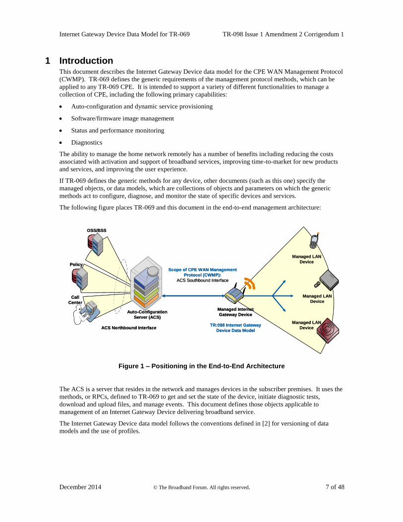
The following figure places TR-069 and this document in the end-to-end management architecture:
OSS/BSS
Call
Center
Policy
Auto-Configuration
Server (ACS)
Managed Internet
Gateway Device
TR:098 Internet Gateway
Device Data Model
Managed LAN
Device
Managed LAN
Device
Managed LAN
Device
Scope of CPE WAN Management
Protocol (CWMP):
ACS Southbound Interface
ACS Northbound Interface
OSS/BSS
Call
Center
Policy
Auto-Configuration
Server (ACS)
Managed Internet
Gateway Device
TR:098 Internet Gateway
Device Data Model
Managed LAN
Device
Managed LAN
Device
Managed LAN
Device
Scope of CPE WAN Management
Protocol (CWMP):
ACS Southbound Interface
ACS Northbound Interface
Figure 1 – Positioning in the End-to-End Architecture
The ACS is a server that resides in the network and manages devices in the subscriber premises. It uses the
methods, or RPCs, defined to TR-069 to get and set the state of the device, initiate diagnostic tests,
download and upload files, and manage events. This document defines those objects applicable to
management of an Internet Gateway Device delivering broadband service.
The Internet Gateway Device data model follows the conventions defined in [2] for versioning of data
models and the use of profiles.
Internet Gateway Device Data Model for TR-069 TR-098 Issue 1 Amendment 2 Corrigendum 1
December 2014 © The Broadband Forum. All rights reserved. 8 of 48
1.1 Terminology
The following terminology is used throughout the series of documents defining the CPE WAN
Management Protocol.
ACS Auto-Configuration Server. This is a component in the broadband network responsible
for auto-configuration of the CPE for advanced services.
ATM Asynchronous Transfer Mode.
B-NT Broadband-Network Termination. A specific type of Broadband CPE used in DSL
networks.
CBR Constant Bitrate.
CPE Customer Premises Equipment; refers to any TR-069-compliant device and therefore
covers both Internet Gateway Devices and LAN-side end devices.
CWMP CPE WAN Management Protocol. Defined in [1], CWMP is a communication protocol
between an ACS and CPE that defines a mechanism for secure auto-configuration of a
CPE and other CPE management functions in a common framework.
Data Model A hierarchical set of Parameters that define the managed objects accessible via TR-069
for a particular device or service.
Device Used interchangeably with CPE.
Event An indication that something of interest has happened that requires the CPE to notify the
ACS.
ICMP Internet Control Message Protocol.
IGD Used interchangeably with Internet Gateway Device.
Internet
Gateway
Device
A CPE device, typically a broadband router that acts as a gateway between the WAN and
the LAN.
IPTV Internet Protocol Television.
ISP Internet Service Provider.
Parameter A name-value pair representing a manageable CPE parameter made accessible to an ACS
for reading and/or writing.
PVC Permanent Virtual Circuit.
QoS Quality of Service.
RG Residential Gateway.
RPC Remote Procedure Call.
RTP Real-time Transport Protocol; RFC 3550 [9].
SAR Segmentation and Reassembly.
VBR Variable Bitrate. An “-rt” suffix indicates “real time”.
VoIP Voice over Internet Protocol.
Internet Gateway Device Data Model for TR-069 TR-098 Issue 1 Amendment 2 Corrigendum 1
December 2014 © The Broadband Forum. All rights reserved. 9 of 48
1.2 Document Conventions
In this Technical Report, several words are used to signify the requirements of the specification. These
words are always capitalized. More information can be found be in RFC 2119 [1].
MUST This word, or the term “REQUIRED”, means that the definition is an absolute
requirement of the specification.
MUST NOT This phrase means that the definition is an absolute prohibition of the specification.
SHOULD This word, or the term “RECOMMENDED”, means that there could exist valid
reasons in particular circumstances to ignore this item, but the full implications need
to be understood and carefully weighed before choosing a different course.
SHOULD NOT This phrase, or the phrase “NOT RECOMMENDED” means that there could exist
valid reasons in particular circumstances when the particular behavior is acceptable or
even useful, but the full implications need to be understood and the case carefully
weighed before implementing any behavior described with this label.
MAY This word, or the term “OPTIONAL”, means that this item is one of an allowed set of
alternatives. An implementation that does not include this option MUST be prepared
to inter-operate with another implementation that does include the option.
The key words “DEPRECATED” and “OBSOLETED” in this Technical Report are to be interpreted as
defined in TR-106 [2].
Internet Gateway Device Data Model for TR-069 TR-098 Issue 1 Amendment 2 Corrigendum 1
December 2014 © The Broadband Forum. All rights reserved. 10 of 48
2 Data Model Definition The normative definition of the InternetGatewayDevice:1 data model is split between several DM Instance
documents (see TR-106 [2] Annex A) and is published at http://www.broadband-forum.org/cwmp. For a
given revision of the data model, the corresponding TR-098 XML document defines the
InternetGatewayDevice:1 model itself and imports additional components from the other XML documents
listed. Each TR-098 HTML document is a report generated from the XML files, and lists a consolidated
view of the InternetGatewayDevice:1 data model in human-readable form.
Internet Gateway Device Data Model for TR-069 TR-098 Issue 1 Amendment 2 Corrigendum 1
December 2014 © The Broadband Forum. All rights reserved. 11 of 48
3 Normative References The following documents are referenced by this specification. A list of currently valid Broadband Forum
Technical Reports is published at http://www.broadband-forum.org.
[1] RFC 2119, Key words for use in RFCs to Indicate Requirement Levels, IETF, 1997
[2] TR-069 Amendment 5, CPE WAN Management Protocol, Broadband Forum, 2013
[3] TR-106 Amendment 7, Data Model Template for TR-069-Enabled Devices, Broadband Forum, 2013
[4] TR-181 Issue 2 Amendment 9, Device Data Model for TR-069, Broadband Forum, 2014
[5] RFC 2597, Assured Forwarding PHB Group, IETF, 1999
[6] RFC 3246, An Expedited Forwarding PHB (Per-Hop Behavior), IETF, 2002
[7] RFC 3261, SIP: Session Initiation Protocol, IETF, 2002
[8] RFC 3435, Media Gateway Control Protocol (MGCP) - Version 1.0, IETF, 2003
[9] RFC 3550, RTP: A Transport Protocol for Real-Time Applications, IETF, 2003
[10] RFC 4566, SDP: Session Description Protocol, IETF, 2006
Internet Gateway Device Data Model for TR-069 TR-098 Issue 1 Amendment 2 Corrigendum 1
December 2014 © The Broadband Forum. All rights reserved. 12 of 48
Annex A. Queuing and Bridging
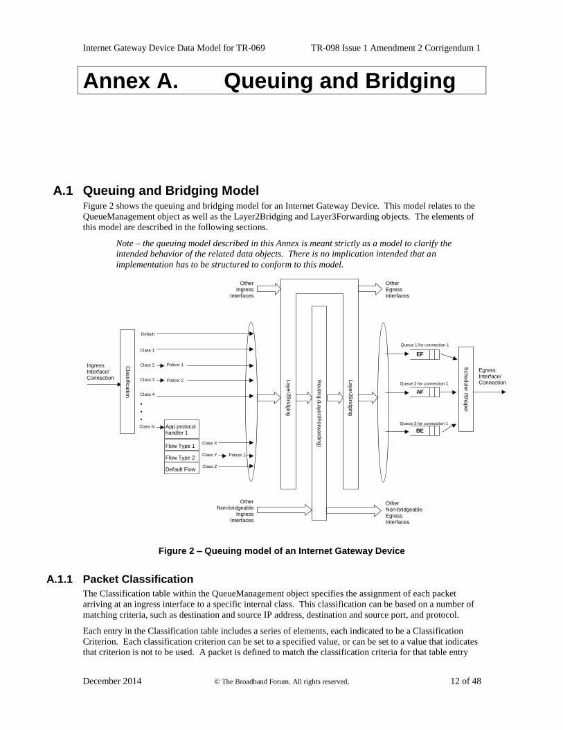
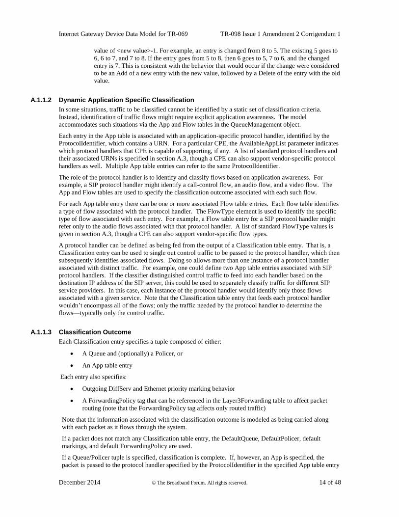
A.1 Queuing and Bridging Model Figure 2 shows the queuing and bridging model for an Internet Gateway Device. This model relates to the
QueueManagement object as well as the Layer2Bridging and Layer3Forwarding objects. The elements of
this model are described in the following sections.
Note – the queuing model described in this Annex is meant strictly as a model to clarify the
intended behavior of the related data objects. There is no implication intended that an
implementation has to be structured to conform to this model.
.
.
.
Class 2
Class 3
Class 4
Class N
EF
AF
Class 1
Queue 1 for connection 1
Queue 2 for connection 1
Policer 1
BE
Queue 3 for connection 1
Ingress Interface/ Connection
Egress Interface/ Connection
Policer 2
Class X
Class Y
Class Z
Default
Cla
ssific
atio
n
App protocol handler 1
Flow Type 1
Flow Type 2
Default Flow
Policer 1
Other Ingress
Interfaces
Other Non-bridgeable Egress Interfaces
Routin
g (L
ayer3
Forw
ard
ing)
Other Non-bridgeable
Ingress Interfaces
Layer2
Brid
gin
g
Layer2
Brid
gin
g
Other Egress Interfaces
Schedule
r /Shaper
Figure 2 – Queuing model of an Internet Gateway Device
A.1.1 Packet Classification
The Classification table within the QueueManagement object specifies the assignment of each packet
arriving at an ingress interface to a specific internal class. This classification can be based on a number of
matching criteria, such as destination and source IP address, destination and source port, and protocol.
Each entry in the Classification table includes a series of elements, each indicated to be a Classification
Criterion. Each classification criterion can be set to a specified value, or can be set to a value that indicates
that criterion is not to be used. A packet is defined to match the classification criteria for that table entry
Internet Gateway Device Data Model for TR-069 TR-098 Issue 1 Amendment 2 Corrigendum 1
December 2014 © The Broadband Forum. All rights reserved. 13 of 48
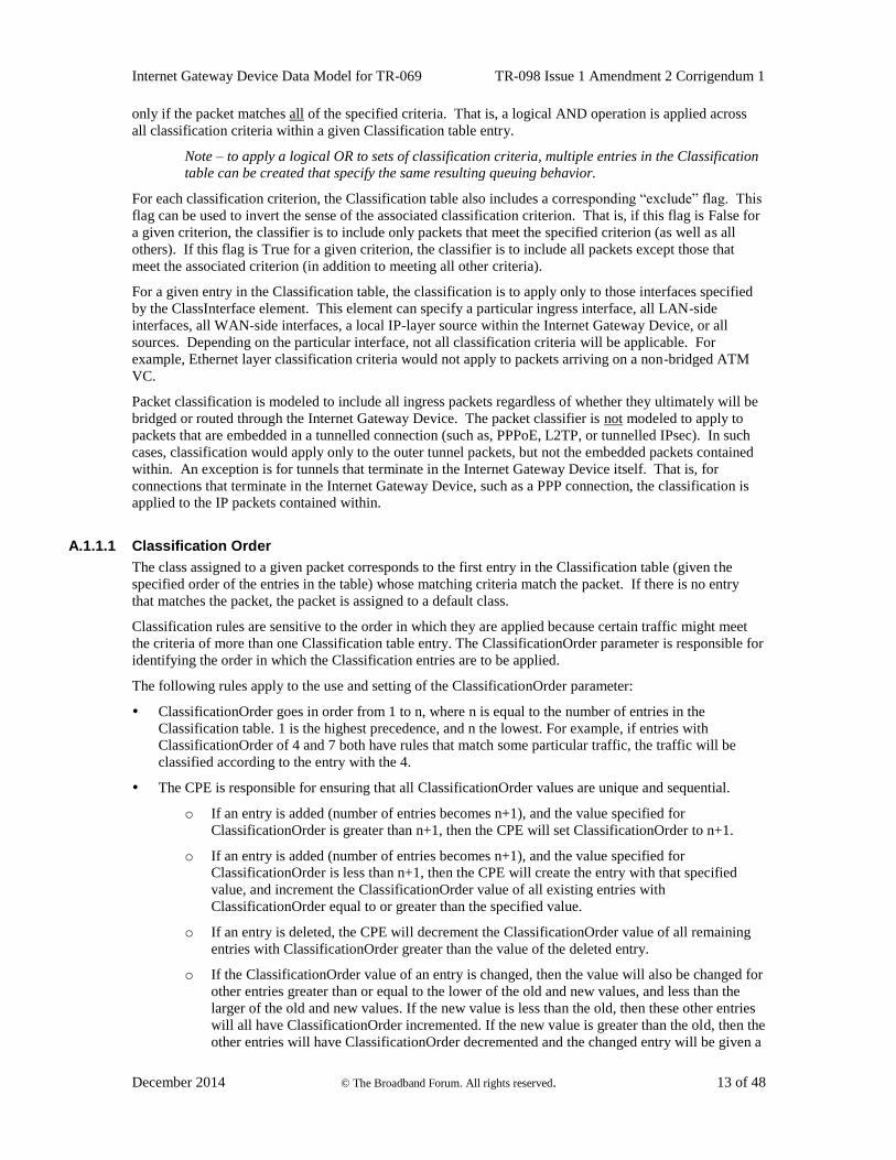
only if the packet matches all of the specified criteria. That is, a logical AND operation is applied across
all classification criteria within a given Classification table entry.
Note – to apply a logical OR to sets of classification criteria, multiple entries in the Classification
table can be created that specify the same resulting queuing behavior.
For each classification criterion, the Classification table also includes a corresponding “exclude” flag. This
flag can be used to invert the sense of the associated classification criterion. That is, if this flag is False for
a given criterion, the classifier is to include only packets that meet the specified criterion (as well as all
others). If this flag is True for a given criterion, the classifier is to include all packets except those that
meet the associated criterion (in addition to meeting all other criteria).
For a given entry in the Classification table, the classification is to apply only to those interfaces specified
by the ClassInterface element. This element can specify a particular ingress interface, all LAN-side
interfaces, all WAN-side interfaces, a local IP-layer source within the Internet Gateway Device, or all
sources. Depending on the particular interface, not all classification criteria will be applicable. For
example, Ethernet layer classification criteria would not apply to packets arriving on a non-bridged ATM
VC.
Packet classification is modeled to include all ingress packets regardless of whether they ultimately will be
bridged or routed through the Internet Gateway Device. The packet classifier is not modeled to apply to
packets that are embedded in a tunnelled connection (such as, PPPoE, L2TP, or tunnelled IPsec). In such
cases, classification would apply only to the outer tunnel packets, but not the embedded packets contained
within. An exception is for tunnels that terminate in the Internet Gateway Device itself. That is, for
connections that terminate in the Internet Gateway Device, such as a PPP connection, the classification is
applied to the IP packets contained within.
A.1.1.1 Classification Order
The class assigned to a given packet corresponds to the first entry in the Classification table (given the
specified order of the entries in the table) whose matching criteria match the packet. If there is no entry
that matches the packet, the packet is assigned to a default class.
Classification rules are sensitive to the order in which they are applied because certain traffic might meet
the criteria of more than one Classification table entry. The ClassificationOrder parameter is responsible for
identifying the order in which the Classification entries are to be applied.
The following rules apply to the use and setting of the ClassificationOrder parameter:
ClassificationOrder goes in order from 1 to n, where n is equal to the number of entries in the
Classification table. 1 is the highest precedence, and n the lowest. For example, if entries with
ClassificationOrder of 4 and 7 both have rules that match some particular traffic, the traffic will be
classified according to the entry with the 4.
The CPE is responsible for ensuring that all ClassificationOrder values are unique and sequential.
o If an entry is added (number of entries becomes n+1), and the value specified for
ClassificationOrder is greater than n+1, then the CPE will set ClassificationOrder to n+1.
o If an entry is added (number of entries becomes n+1), and the value specified for
ClassificationOrder is less than n+1, then the CPE will create the entry with that specified
value, and increment the ClassificationOrder value of all existing entries with
ClassificationOrder equal to or greater than the specified value.
o If an entry is deleted, the CPE will decrement the ClassificationOrder value of all remaining
entries with ClassificationOrder greater than the value of the deleted entry.
o If the ClassificationOrder value of an entry is changed, then the value will also be changed for
other entries greater than or equal to the lower of the old and new values, and less than the
larger of the old and new values. If the new value is less than the old, then these other entries
will all have ClassificationOrder incremented. If the new value is greater than the old, then the
other entries will have ClassificationOrder decremented and the changed entry will be given a
Internet Gateway Device Data Model for TR-069 TR-098 Issue 1 Amendment 2 Corrigendum 1
December 2014 © The Broadband Forum. All rights reserved. 14 of 48
value of <new value>-1. For example, an entry is changed from 8 to 5. The existing 5 goes to
6, 6 to 7, and 7 to 8. If the entry goes from 5 to 8, then 6 goes to 5, 7 to 6, and the changed
entry is 7. This is consistent with the behavior that would occur if the change were considered
to be an Add of a new entry with the new value, followed by a Delete of the entry with the old
value.
A.1.1.2 Dynamic Application Specific Classification
In some situations, traffic to be classified cannot be identified by a static set of classification criteria.
Instead, identification of traffic flows might require explicit application awareness. The model
accommodates such situations via the App and Flow tables in the QueueManagement object.
Each entry in the App table is associated with an application-specific protocol handler, identified by the
ProtocolIdentifier, which contains a URN. For a particular CPE, the AvailableAppList parameter indicates
which protocol handlers that CPE is capable of supporting, if any. A list of standard protocol handlers and
their associated URNs is specified in section A.3, though a CPE can also support vendor-specific protocol
handlers as well. Multiple App table entries can refer to the same ProtocolIdentifier.
The role of the protocol handler is to identify and classify flows based on application awareness. For
example, a SIP protocol handler might identify a call-control flow, an audio flow, and a video flow. The
App and Flow tables are used to specify the classification outcome associated with each such flow.
For each App table entry there can be one or more associated Flow table entries. Each flow table identifies
a type of flow associated with the protocol handler. The FlowType element is used to identify the specific
type of flow associated with each entry. For example, a Flow table entry for a SIP protocol handler might
refer only to the audio flows associated with that protocol handler. A list of standard FlowType values is
given in section A.3, though a CPE can also support vendor-specific flow types.
A protocol handler can be defined as being fed from the output of a Classification table entry. That is, a
Classification entry can be used to single out control traffic to be passed to the protocol handler, which then
subsequently identifies associated flows. Doing so allows more than one instance of a protocol handler
associated with distinct traffic. For example, one could define two App table entries associated with SIP
protocol handlers. If the classifier distinguished control traffic to feed into each handler based on the
destination IP address of the SIP server, this could be used to separately classify traffic for different SIP
service providers. In this case, each instance of the protocol handler would identify only those flows
associated with a given service. Note that the Classification table entry that feeds each protocol handler
wouldn’t encompass all of the flows; only the traffic needed by the protocol handler to determine the
flows—typically only the control traffic.
A.1.1.3 Classification Outcome
Each Classification entry specifies a tuple composed of either:
A Queue and (optionally) a Policer, or
An App table entry
Each entry also specifies:
Outgoing DiffServ and Ethernet priority marking behavior
A ForwardingPolicy tag that can be referenced in the Layer3Forwarding table to affect packet
routing (note that the ForwardingPolicy tag affects only routed traffic)
Note that the information associated with the classification outcome is modeled as being carried along
with each packet as it flows through the system.
If a packet does not match any Classification table entry, the DefaultQueue, DefaultPolicer, default
markings, and default ForwardingPolicy are used.
If a Queue/Policer tuple is specified, classification is complete. If, however, an App is specified, the
packet is passed to the protocol handler specified by the ProtocolIdentifier in the specified App table entry
Internet Gateway Device Data Model for TR-069 TR-098 Issue 1 Amendment 2 Corrigendum 1
December 2014 © The Broadband Forum. All rights reserved. 15 of 48
for additional classification (see section A.1.1.2). If any of the identified flows match the FlowType
specified in any Flow table entry corresponding to the given App table entry (this correspondence is
indicated by the App identifier), the specified tuple and markings for that Flow table entry is used for
packets in that flow. Other flows associated with the application, but not explicitly identified, use the
default tuple and markings specified for that App table entry.
A.1.2 Policing
The Policer table defines the policing parameters for ingress packets identified by either a Classification
table entry (or the default classification) or a dynamic flow identified by a protocol handler identified in the
App table.
Each Policer table entry specifies the packet handling characteristics, including the rate requirements and
behavior when these requirements are exceeded.
A.1.3 Queuing and Scheduling
The Queue table specifies the number and types of queues, queue parameters, shaping behavior, and
scheduling algorithm to use. Each Queue table entry specifies a set of egress interfaces for which a queue
with the corresponding characteristics needs to exist.
Note – If the CPE can determine that among the interfaces specified for a queue to exist, packets
classified into that queue cannot egress to a subset of those interfaces (from knowledge of the
current routing and bridging configuration), the CPE can choose not to instantiate the queue on
those interfaces.
Note – Packets classified into a queue that exit through an interface for which the queue is not
specified to exist, will instead use the default queuing behavior. The default queue itself will exist
on all egress interfaces.
The model defined here is not intended to restrict where the queuing is implemented in an actual
implementation. In particular, it is up to the particular implementation to determine at what protocol layer
it is most appropriate to implement the queuing behavior (IP layer, Ethernet MAC layer, ATM layer, etc.).
In some cases, however, the QueueManagement configuration would restrict the choice of layer where
queueing can be implemented. For example, if a queue is specified to carry traffic that is bridged, then it
could not be implemented as an IP-layer queue.
Note – care needs to be taken to avoid having multiple priority queues multiplexed onto a single
connection that is rate shaped. In such cases, the possibility exists that high priority traffic can be
held back due to rate limits of the overall connection exceeded by lower priority traffic. Where
possible, each priority queue will be shaped independently using the shaping parameters in the
Queue table.
The scheduling parameters defined in the Queue table apply to the first level of what might be a more
general scheduling hierarchy. This specification does not specify the rules that an implementation needs to
apply to determine the most appropriate scheduling hierarchy given the scheduling parameters defined in
the Queue table.
As an example, take a situation where the output of four distinct queues is to be multiplexed into a single
connection, and two entries share one set of scheduling parameters while the other two entries share a
different set of scheduling parameters. In this case, it might be appropriate to implement this as a
scheduling hierarchy with the first two queues multiplexed with a scheduler defined by the first pair, and
the second two queues being multiplexed with a scheduler defined by the second pair. The lower layers of
this scheduling hieararchy cannot be directly determined from the content of the Queue table.
Internet Gateway Device Data Model for TR-069 TR-098 Issue 1 Amendment 2 Corrigendum 1
December 2014 © The Broadband Forum. All rights reserved. 16 of 48
A.1.4 Bridging
For each interface, the output of the classifier is modeled to feed a set of layer 2 bridges as specified by the
Layer2Bridging object. Each bridge specifies layer 2 connectivity between one or more layer 2 LAN
and/or WAN interfaces, and optionally one or more layer 3 connections to the local router.
Each bridge corresponds to a single entry in the Bridge table of the Layer2Bridging object. Each entry
contains (by reference) one or more Filter table entries. Each Filter table entry specifies an interface or set
of interfaces to include in the bridge, and can also specify layer 2 filter criteria to selectively bridge traffic
among the specified interfaces.
Note – each Bridge table entry can contain a Bridge Port table (as a sub-object). If this table is
supported, it explicitly defines which interfaces are to be included in the bridge, and also defines
various bridge port parameters.
Each Filter table entry selects one or more interfaces among those listed in the AvailableInterface table.
This table would normally include all layer 2 interfaces that include an Ethernet MAC layer. This would
exclude, for example, a non-bridged ATM VC carrying IPoA or PPPoA. Each entry in the Filter table
refers to a specific layer 2 interface. A Filter table entry can also include LAN-side or WAN-side layer 3
connections to the local router, such as PPP or IP connections. When using Layer2Bridging to include a
layer 3 connection in a bridge, this overrides the default association of that connection with a layer 2 object
as indicated by the IGD data model connection object hierarchy, and results in an update of the IGD data
model hierarchy. The implications of this are explained in Annex A.6.
Note – from the point of view of a bridge, packets arriving into the bridge from the local router
(either LAN-side or WAN-side) are treated as ingress packets, even though the same packets,
which just left the router, are treated as egress from the point of view of the router. For example,
a Filter table entry might admit packets on ingress to the bridge from a particular WANIPConn-
ection, which means that it admits packets on their way out of the router over this layer 3 conn-
ection.
A.1.4.1 Filtering
Traffic from a given interface (or set of interfaces) can be selectively admitted to a given Bridge, rather
than bridging all traffic from that interface. Each entry in the Filter table includes a series of classification
criteria. Each classification criterion can be set to a specified value, or can be set to a value that indicates
that criterion is not to be used. A packet is admitted to the Bridge only if the packet matches all of the
specified criteria. That is, a logical AND operation is applied across all classification criteria within a
given Filter table entry.
Note – to apply a logical OR to sets of classification criteria, multiple entries in the Filter table
can be created that refer to the same interfaces and the same Bridge table entry.
Note – a consequence of the above rule is that, if a packet does not match the criteria of any of the
enabled Filter table entries, then it will not be admitted to any bridges, i.e. it will be dropped. As
a specific example of this, if none of the enabled Filter table entries reference a given interface,
then all packets arriving on that interface will be dropped.
For each classification criterion, the Filter table also includes a corresponding “exclude” flag. This flag can
be used to invert the sense of the associated classification criterion. That is, if this flag is False for a given
criterion, the Bridge will admit only packets that meet the specified criterion (as well as all other criteria).
If this flag is True for a given criterion, the Bridge will admit all packets except those that meet the
associated criterion (in addition to meeting all other criteria).
Note that because the classification criteria are based on layer 2 packet information, if the selected interface
for a given Filter table entry is a layer 3 connection from the local router, the layer 2 classification criteria
do not apply.
Internet Gateway Device Data Model for TR-069 TR-098 Issue 1 Amendment 2 Corrigendum 1
December 2014 © The Broadband Forum. All rights reserved. 17 of 48
A.1.4.2 Exclusivity Order
Each Filter table entry is defined as either exclusive or non-exclusive. Any packet that matches the filter
criteria of one or more exclusive filters is admitted to the Bridge associated with the first exclusive entry in
the Filter table (relative to the specified ExclusivityOrder).
If there is no exclusive filter that matches a packet, then the packet is admitted to all Bridges associated
with non-exclusive filters that match the packet.
The following rules apply to the use and setting of the ExclusivityOrder parameter:
If the ExclusivityOrder is zero, the filter is defined to be non-exclusive.
If the ExclusivityOrder is one or greater, the filter is defined to be exclusive.
Among exclusive filters, the ExclusivityOrder goes in order from 1 to n, where n is equal to the
number of exclusive filters. 1 is the highest precedence, and n the lowest.
The CPE is responsible for ensuring that all ExclusivityOrder values among exclusive filters are
unique and sequential.
o If an exclusive filter is added (number of exclusive filters becomes n+1) or a non-exclusive
filter is changed to be exclusive, and the value specified for ExclusivityOrder is greater than
n+1, then the CPE will set ExclusivityOrder to n+1.
o If an exclusive filter is added (number of entries becomes n+1) or a non-exclusive filter is
changed to be exclusive, and the value specified for ExclusivityOrder is less than n+1, then
the CPE will create the entry with that specified value, and increment the ExclusivityOrder
value of all existing exclusive filters with ExclusivityOrder equal to or greater than the
specified value.
o If an exclusive filter is deleted or an exclusive filter is changed to non-exclusive, the CPE will
decrement the ExclusivityOrder value of all remaining exclusive filter with ExclusivityOrder
greater than the value of the deleted entry.
o If the ExclusivityOrder value of an exclusive filter is changed, then the value will also be
changed for other exclusive filters greater than or equal to the lower of the old and new
values, and less than the larger of the old and new values. If the new value is less than the old,
then these other entries will all have ExclusivityOrder incremented. If the new value is greater
than the old, then the other entries will have ExclusivityOrder decremented and the changed
entry will be given a value of <new value>-1. For example, an entry is changed from 8 to 5.
The existing 5 goes to 6, 6 to 7, and 7 to 8. If the entry goes from 5 to 8, then 6 goes to 5, 7 to
6, and the changed entry is 7. This is consistent with the behavior that would occur if the
change were considered to be an Add of a new exclusive filter with the new value, followed
by a Delete of the exclusive filter with the old value.
A.1.4.3 Egress from a Bridge
Packets admitted to a bridge from any interface are bridged across all of the interfaces considered part of
that bridge. An interface is considered part of a bridge if it is specified by any of the Filter table or
Marking table entries that are associated with the bridge. That is, the union of all interfaces specified either
for potential admission into the bridge or for special marking treatment on egress are considered part of the
bridge. This can include both layer 2 interfaces as well as layer 3 connections to the local router.
Note – if the Bridge Port table is supported, it explicitly defines which interfaces are considered
part of the bridge. This overrides the implicit definition that is provided by the Filter and Marking
tables.
Note – a consequence of the above rukes is that, if no layer 3 interfaces are part of a given bridge,
then no packets that are admitted to that bridge can be passed to the IP layer.
For a given bridge, packets on egress can optionally be marked distinctly for specific interfaces. The
Marking table allows the CPE to be configured to selectively either remove all VLANID/priority marking
Internet Gateway Device Data Model for TR-069 TR-098 Issue 1 Amendment 2 Corrigendum 1
December 2014 © The Broadband Forum. All rights reserved. 18 of 48
from a packet on egress, or modify the VLANID and/or Ethernet priority marking on egress. This can be
done selectively per interface.
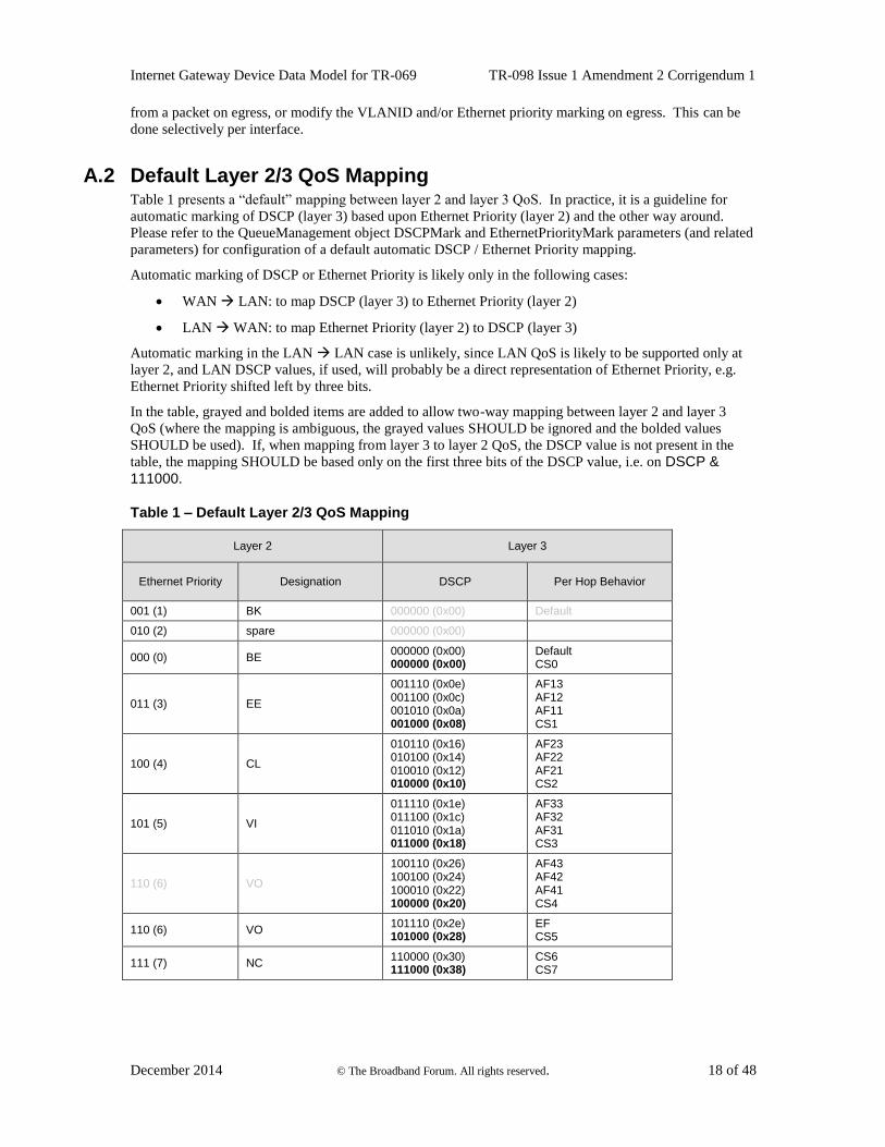
A.2 Default Layer 2/3 QoS Mapping Table 1 presents a “default” mapping between layer 2 and layer 3 QoS. In practice, it is a guideline for
automatic marking of DSCP (layer 3) based upon Ethernet Priority (layer 2) and the other way around.
Please refer to the QueueManagement object DSCPMark and EthernetPriorityMark parameters (and related
parameters) for configuration of a default automatic DSCP / Ethernet Priority mapping.
Automatic marking of DSCP or Ethernet Priority is likely only in the following cases:
WAN LAN: to map DSCP (layer 3) to Ethernet Priority (layer 2)
LAN WAN: to map Ethernet Priority (layer 2) to DSCP (layer 3)
Automatic marking in the LAN LAN case is unlikely, since LAN QoS is likely to be supported only at
layer 2, and LAN DSCP values, if used, will probably be a direct representation of Ethernet Priority, e.g.
Ethernet Priority shifted left by three bits.
In the table, grayed and bolded items are added to allow two-way mapping between layer 2 and layer 3
QoS (where the mapping is ambiguous, the grayed values SHOULD be ignored and the bolded values
SHOULD be used). If, when mapping from layer 3 to layer 2 QoS, the DSCP value is not present in the
table, the mapping SHOULD be based only on the first three bits of the DSCP value, i.e. on DSCP &
111000.
Table 1 – Default Layer 2/3 QoS Mapping
Layer 2 Layer 3
Ethernet Priority Designation DSCP Per Hop Behavior
001 (1) BK 000000 (0x00) Default
010 (2) spare 000000 (0x00)
000 (0) BE 000000 (0x00) 000000 (0x00)
Default CS0
011 (3) EE
001110 (0x0e) 001100 (0x0c) 001010 (0x0a) 001000 (0x08)
AF13 AF12 AF11 CS1
100 (4) CL
010110 (0x16) 010100 (0x14) 010010 (0x12) 010000 (0x10)
AF23 AF22 AF21 CS2
101 (5) VI
011110 (0x1e) 011100 (0x1c) 011010 (0x1a) 011000 (0x18)
AF33 AF32 AF31 CS3
110 (6) VO
100110 (0x26) 100100 (0x24) 100010 (0x22) 100000 (0x20)
AF43 AF42 AF41 CS4
110 (6) VO 101110 (0x2e) 101000 (0x28)
EF CS5
111 (7) NC 110000 (0x30) 111000 (0x38)
CS6 CS7
Internet Gateway Device Data Model for TR-069 TR-098 Issue 1 Amendment 2 Corrigendum 1
December 2014 © The Broadband Forum. All rights reserved. 19 of 48
A.3 URN Definitions for App and Flow Tables
A.3.1 ProtocolIdentifier
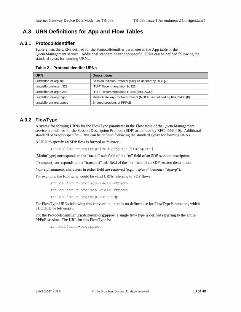
Table 2 lists the URNs defined for the ProtocolIdentifier parameter in the App table of the
QueueManagement service. Additional standard or vendor-specific URNs can be defined following the
standard synax for forming URNs.
Table 2 – ProtocolIdentifer URNs
URN Description
urn:dslforum-org:sip Session Initiaion Protocol (SIP) as defined by RFC [7]
urn:dslforum-org:h.323 ITU-T Recommendation H.323
urn:dslforum-org:h.248 ITU-T Recommendation H.248 (MEGACO)
urn:dslforum-org:mgcp Media Gateway Control Protocol (MGCP) as defined by RFC 3435 [8]
urn:dslforum-org:pppoe Bridged sessions of PPPoE
A.3.2 FlowType
A syntax for forming URNs for the FlowType parameter in the Flow table of the QueueManagement
service are defined for the Session Description Protocol (SDP) as defined by RFC 4566 [10]. Additional
standard or vendor-specific URNs can be defined following the standard synax for forming URNs.
A URN to specify an SDP flow is formed as follows:
urn:dslforum-org:sdp-[MediaType]-[Transport]
[MediaType] corresponds to the “media” sub-field of the “m” field of an SDP session description.
[Transport] corresponds to the “transport” sub-field of the “m” field of an SDP session description.
Non-alphanumeric characters in either field are removed (e.g., “rtp/avp” becomes “rtpavp”).
For example, the following would be valid URNs referring to SDP flows:
urn:dslforum-org:sdp-audio-rtpavp
urn:dslforum-org:sdp-video-rtpavp
urn:dslforum-org:sdp-data-udp
For FlowType URNs following this convention, there is no defined use for FlowTypeParameters, which
SHOULD be left empty.
For the ProtocolIdentifier urn:dslforum-org:pppoe, a single flow type is defined referring to the entire
PPPoE session. The URL for this FlowType is:
urn:dslforum-org:pppoe
Internet Gateway Device Data Model for TR-069 TR-098 Issue 1 Amendment 2 Corrigendum 1
December 2014 © The Broadband Forum. All rights reserved. 20 of 48
A.3.3 FlowTypeParameters
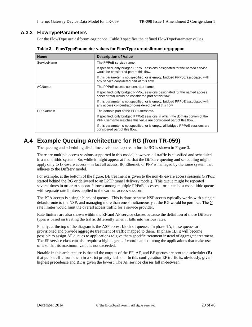
For the FlowType urn:dslforum-org:pppoe, Table 3 specifies the defined FlowTypeParameter values.
Table 3 – FlowTypeParameter values for FlowType urn:dslforum-org:pppoe
Name Description of Value
ServiceName The PPPoE service name.
If specified, only bridged PPPoE sessions designated for the named service would be considered part of this flow.
If this parameter is not specified, or is empty, bridged PPPoE associated with any service considered part of this flow.
ACName The PPPoE access concentrator name.
If specified, only bridged PPPoE sessions designated for the named access concentrator would be considered part of this flow.
If this parameter is not specified, or is empty, bridged PPPoE associated with any access concentrator considered part of this flow.
PPPDomain The domain part of the PPP username.
If specified, only bridged PPPoE sessions in which the domain portion of the PPP username matches this value are considered part of this flow.
If this parameter is not specified, or is empty, all bridged PPPoE sessions are considered part of this flow.
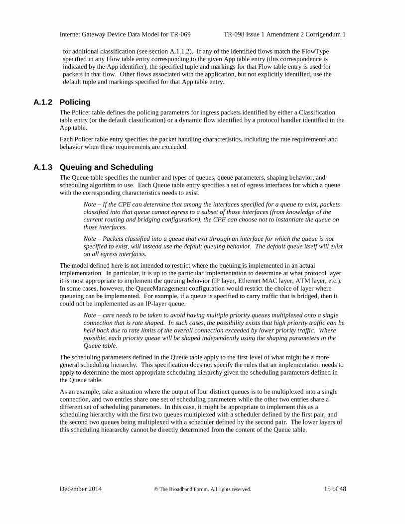
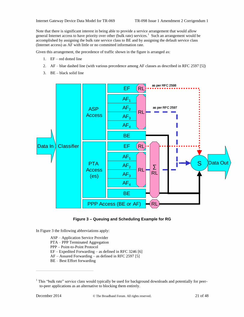
A.4 Example Queuing Architecture for RG (from TR-059) The queuing and scheduling discipline envisioned upstream for the RG is shown in Figure 3.
There are multiple access sessions supported in this model, however, all traffic is classified and scheduled
in a monolithic system. So, while it might appear at first that the Diffserv queuing and scheduling might
apply only to IP-aware access – in fact all access, IP, Ethernet, or PPP is managed by the same system that
adheres to the Diffserv model.
For example, at the bottom of the figure, BE treatment is given to the non-IP-aware access sessions (PPPoE
started behind the RG or delivered to an L2TP tunnel delivery model). This queue might be repeated
several times in order to support fairness among multiple PPPoE accesses – or it can be a monolithic queue
with separate rate limiters applied to the various access sessions.
The PTA access is a single block of queues. This is done because NSP access typically works with a single
default route to the NSP, and managing more than one simultaneously at the RG would be perilous. The ∑
rate limiter would limit the overall access traffic for a service provider.
Rate limiters are also shown within the EF and AF service classes because the definition of those Diffserv
types is based on treating the traffic differently when it falls into various rates.
Finally, at the top of the diagram is the ASP access block of queues. In phase 1A, these queues are
provisioned and provide aggregate treatment of traffic mapped to them. In phase 1B, it will become
possible to assign AF queues to applications to give them specific treatment instead of aggregate treatment.
The EF service class can also require a high degree of coordination among the applications that make use
of it so that its maximum value is not exceeded.
Notable in this architecture is that all the outputs of the EF, AF, and BE queues are sent to a scheduler (S)
that pulls traffic from them in a strict priority fashion. In this configuration EF traffic is, obviously, given
highest precedence and BE is given the lowest. The AF service classes fall in-between.
Internet Gateway Device Data Model for TR-069 TR-098 Issue 1 Amendment 2 Corrigendum 1
December 2014 © The Broadband Forum. All rights reserved. 21 of 48
Note that there is significant interest in being able to provide a service arrangement that would allow
general Internet access to have priority over other (bulk rate) services.1 Such an arrangement would be
accomplished by assigning the bulk rate service class to BE and by assigning the default service class
(Internet access) as AF with little or no committed information rate.
Given this arrangement, the precedence of traffic shown in the figure is arranged as:
1. EF – red dotted line
2. AF – blue dashed line (with various precedence among AF classes as described in RFC 2597 [5])
3. BE – black solid line
Data In
Data Out
Classifier
PPP Access (BE or AF)
EF
PTA
Access
(es)
BE
AF1
ASP
Access
S
AF2
AF4
AF3
EF
BE
AF1
AF2
AF4
AF3
RL
RL
RL
∑
RL
as per RFC 2597
as per RFC 2598
RL
RL
Data In
Data Out
Classifier
PPP Access (BE or AF)
EF
PTA
Access
(es)
BE
AF1
ASP
Access
S
AF2
AF4
AF3
EF
BE
AF1
AF2
AF4
AF3
RL
RL
RL
∑
RL
as per RFC 2597
as per RFC 2598
RL
RL
Figure 3 – Queuing and Scheduling Example for RG
In Figure 3 the following abbreviations apply:
ASP – Application Service Provider
PTA – PPP Terminated Aggregation
PPP – Point-to-Point Protocol
EF – Expedited Forwarding – as defined in RFC 3246 [6]
AF – Assured Forwarding – as defined in RFC 2597 [5]
BE – Best Effort forwarding
1 This “bulk rate” service class would typically be used for background downloads and potentially for peer-
to-peer applications as an alternative to blocking them entirely.
Internet Gateway Device Data Model for TR-069 TR-098 Issue 1 Amendment 2 Corrigendum 1
December 2014 © The Broadband Forum. All rights reserved. 22 of 48
RL – Rate Limiter
∑RL – Summing Rate Limiter (limits multiple flows)
S – Scheduler
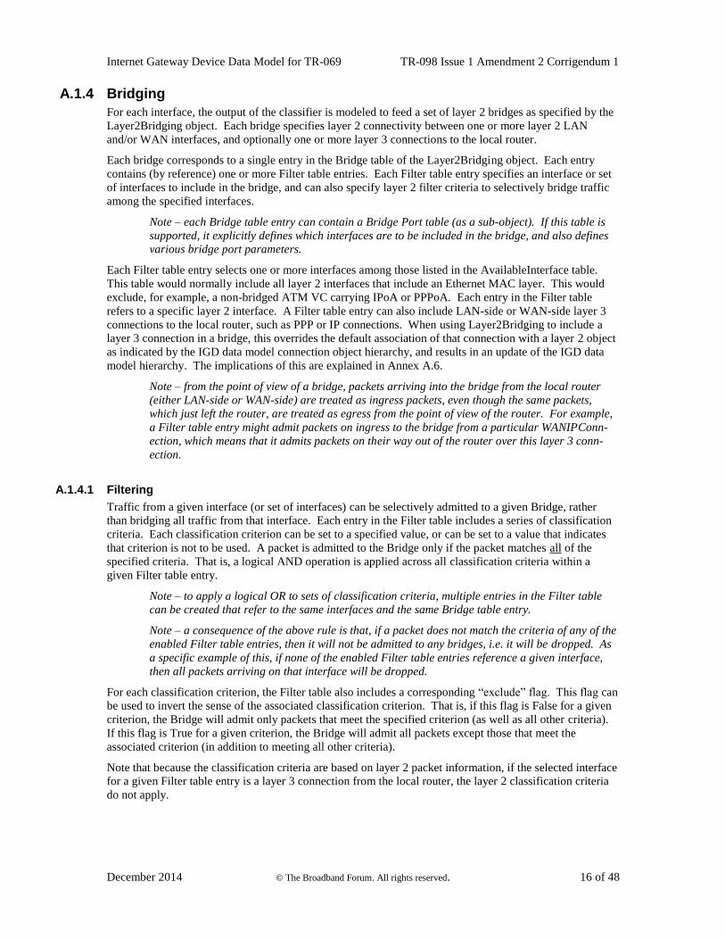
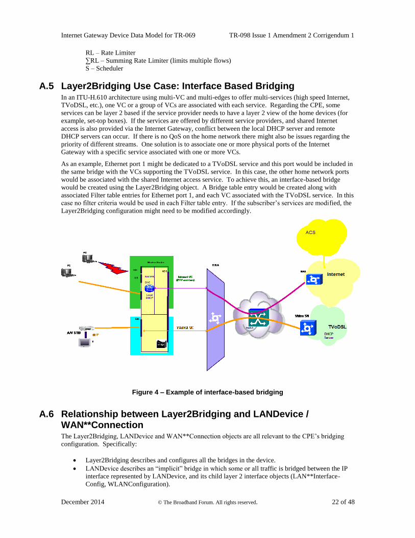
A.5 Layer2Bridging Use Case: Interface Based Bridging In an ITU-H.610 architecture using multi-VC and multi-edges to offer multi-services (high speed Internet,
TVoDSL, etc.), one VC or a group of VCs are associated with each service. Regarding the CPE, some
services can be layer 2 based if the service provider needs to have a layer 2 view of the home devices (for
example, set-top boxes). If the services are offered by different service providers, and shared Internet
access is also provided via the Internet Gateway, conflict between the local DHCP server and remote
DHCP servers can occur. If there is no QoS on the home network there might also be issues regarding the
priority of different streams. One solution is to associate one or more physical ports of the Internet
Gateway with a specific service associated with one or more VCs.
As an example, Ethernet port 1 might be dedicated to a TVoDSL service and this port would be included in
the same bridge with the VCs supporting the TVoDSL service. In this case, the other home network ports
would be associated with the shared Internet access service. To achieve this, an interface-based bridge
would be created using the Layer2Bridging object. A Bridge table entry would be created along with
associated Filter table entries for Ethernet port 1, and each VC associated with the TVoDSL service. In this
case no filter criteria would be used in each Filter table entry. If the subscriber’s services are modified, the
Layer2Bridging configuration might need to be modified accordingly.
Figure 4 – Example of interface-based bridging
A.6 Relationship between Layer2Bridging and LANDevice / WAN**Connection The Layer2Bridging, LANDevice and WAN**Connection objects are all relevant to the CPE’s bridging
configuration. Specifically:
Layer2Bridging describes and configures all the bridges in the device.
LANDevice describes an “implicit” bridge in which some or all traffic is bridged between the IP
interface represented by LANDevice, and its child layer 2 interface objects (LAN**Interface-
Config, WLANConfiguration).
Internet Gateway Device Data Model for TR-069 TR-098 Issue 1 Amendment 2 Corrigendum 1
December 2014 © The Broadband Forum. All rights reserved. 23 of 48
WANPPPConnection with ConnectionType = “PPPoE_Bridged” describes a bridge.
WANIPConnection with ConnectionType = “IP_Bridged” describes a bridge.
Only Layer2Bridging provides a complete description of the device’s bridging configuration. The
definitions of the above-mentioned objects and parameters make it clear that they must all be consistent
with each other.
This consistency requirement is perhaps best understood by realizing that, below the InternetGateway-
Device data model, there is an underlying device and configuration. The TR-069 objects are just a way of
representing and configuring items that are aspects of the device and its configuration, and which are
nothing to do with TR-069 per se. Such items could also be configured independently of TR-069, e.g. via a
vendor configuration file or a user interface.
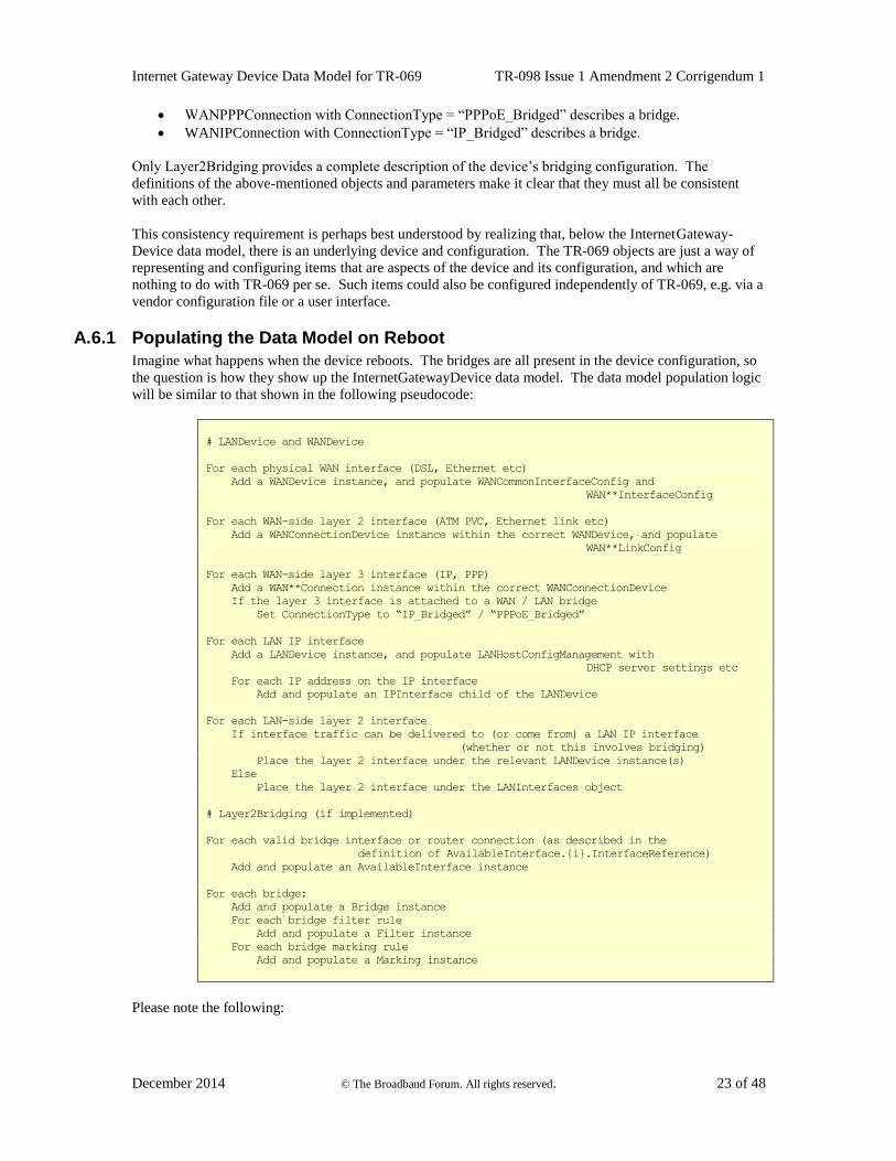
A.6.1 Populating the Data Model on Reboot
Imagine what happens when the device reboots. The bridges are all present in the device configuration, so
the question is how they show up the InternetGatewayDevice data model. The data model population logic
will be similar to that shown in the following pseudocode:
# LANDevice and WANDevice
For each physical WAN interface (DSL, Ethernet etc)
Add a WANDevice instance, and populate WANCommonInterfaceConfig and
WAN**InterfaceConfig
For each WAN-side layer 2 interface (ATM PVC, Ethernet link etc)
Add a WANConnectionDevice instance within the correct WANDevice, and populate
WAN**LinkConfig
For each WAN-side layer 3 interface (IP, PPP)
Add a WAN**Connection instance within the correct WANConnectionDevice
If the layer 3 interface is attached to a WAN / LAN bridge
Set ConnectionType to “IP_Bridged” / “PPPoE_Bridged”
For each LAN IP interface
Add a LANDevice instance, and populate LANHostConfigManagement with
DHCP server settings etc
For each IP address on the IP interface
Add and populate an IPInterface child of the LANDevice
For each LAN-side layer 2 interface
If interface traffic can be delivered to (or come from) a LAN IP interface
(whether or not this involves bridging)
Place the layer 2 interface under the relevant LANDevice instance(s)
Else
Place the layer 2 interface under the LANInterfaces object
# Layer2Bridging (if implemented)
For each valid bridge interface or router connection (as described in the
definition of AvailableInterface.{i}.InterfaceReference)
Add and populate an AvailableInterface instance
For each bridge:
Add and populate a Bridge instance
For each bridge filter rule
Add and populate a Filter instance
For each bridge marking rule
Add and populate a Marking instance
Please note the following:
Internet Gateway Device Data Model for TR-069 TR-098 Issue 1 Amendment 2 Corrigendum 1
December 2014 © The Broadband Forum. All rights reserved. 24 of 48
The criterion for setting the WAN**Connection ConnectionType to “IP_Bridged” or “PPPoE_-
Bridged” is “layer 3 interface is attached to a WAN / LAN bridge”. This is the only way in which
WAN**Connection can indicate the existence of such a bridge.
The criterion for including a layer 2 interface under a LANDevice is “traffic can be delivered to
(or come from)”. This just means that there is at least one (enabled) bridge filter that can allow
traffic to flow between the LANDevice’s IP interface and the layer 2 interface. LANDevice is
unable to represent the details of the filter rules.
The pseudocode does not mention whether objects are enabled or disabled. Consider disabling a
bridge (not the TR-069 object… an actual bridge). This would be expected to disable the
corresponding Layer2Bridging Bridge object. The bridge is not explicitly modeled on the
LANDevice side, but the LANDevice’s IP interface is layered on top of the bridge, and can be up
only if the bridge is up.
A.6.2 Updating the Data Model on Configuration Changes
Now imagine what happens when the device configuration changes in a way that affects any of the objects
mentioned in the pseudocode. Conceptually, all of the objects are deleted and then re-populated by the
pseudocode logic. In practice, of course, the implementation would probably make only the minimal
changes in moving from the old to the new state.
A.6.3 Bridging Behavior when Layer2Bridging is not Implemented
If Layer2Bridging is not implemented, then bridging cannot be configured using the InternetGateway-
Device data model. The only possible bridge-related configuration parameter is WAN**Connection’s
ConnectionType. This makes sense only if there is a single (or at least a default) LANDevice, because
there is no way to select which LANDevice to attach to the bridge. Therefore, on devices that don’t
implement Layer2Bridging, any non-trivial bridging configuration will have to use vendor-specific
configuration files, and the remarks in the previous sections will still apply.
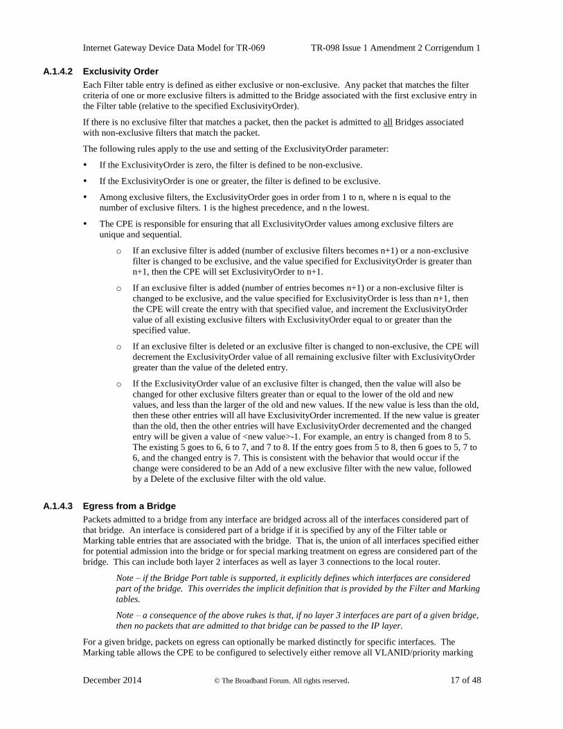
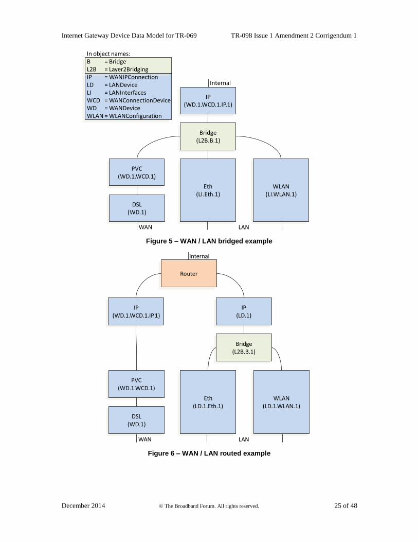
A.6.4 Case Studies
This section considers two case studies, each of which illustrates a different aspect of the relationship
between Layer2Bridging and WAN**Connection. Both case studies refer to the example configurations of
Figure 5and Figure 6.
Internet Gateway Device Data Model for TR-069 TR-098 Issue 1 Amendment 2 Corrigendum 1
December 2014 © The Broadband Forum. All rights reserved. 25 of 48
In object names:B = BridgeL2B = Layer2BridgingIP = WANIPConnectionLD = LANDeviceLI = LANInterfacesWCD = WANConnectionDeviceWD = WANDeviceWLAN = WLANConfiguration
PVC(WD.1.WCD.1)
Bridge(L2B.B.1)
Eth(LI.Eth.1)
DSL(WD.1)
WLAN(LI.WLAN.1)
IP(WD.1.WCD.1.IP.1)
Internal
WAN LAN
Figure 5 – WAN / LAN bridged example
IP(LD.1)
PVC(WD.1.WCD.1)
Bridge(L2B.B.1)
Eth(LD.1.Eth.1)
DSL(WD.1)
WLAN(LD.1.WLAN.1)
IP(WD.1.WCD.1.IP.1)
Router
Internal
WAN LAN
Figure 6 – WAN / LAN routed example
Internet Gateway Device Data Model for TR-069 TR-098 Issue 1 Amendment 2 Corrigendum 1
December 2014 © The Broadband Forum. All rights reserved. 26 of 48
A.6.4.1 Creating a WANIPConnection Instance
In the bridged configuration of Figure 5, suppose that InternetGatewayDevice.WANDevice.1.WAN-
ConnectionDevice.1.WANIPConnection.1 has just been created. There is a bridge “between” it and its
parent WANConnectionDevice, but this is indicated in the WANDevice object hierarchy only via WANIP-
Connection’s ConnectionType value of “IP_Bridged”. If Layer2Bridging is implemented, this bridge will
of course be modeled there.
In the routed configuration of Figure 6, similarly suppose that InternetGatewayDevice.WANDevice.1.-
WANConnectionDevice.1.WANIPConnection.1 has just been created. In this case, there is no WAN-side
bridge, which will be indicated by WANIPConnection’s ConnectionType value of “IP_Routed”.
A.6.4.2 Attaching a WANConnectionDevice Instance to a Bridge
The routed configuration of of Figure 6 can be converted to the bridged configuration of Figure 5 by using
Layer2Bridging to re-configure the bridge as follows:
Detach the LAN IP interface InternetGatewayDevice.LANDevice.1
Attach the PVC InternetGatewayDevice.WANDevice.1.WANConnectionDevice.1
The WAN IP interface InternetGatewayDevice.WANConnectionDevice.1.WANIPConnection.1, which
was previously attached to the PVC InternetGatewayDevice.WANDevice.1.WANConnectionDevice.1 will
automatically be attached to the bridge. As in the previous use case, the bridge is “between” it and its
parent WANConnectionDevice.
The only visible change in the WANDevice object hierarchy will be that WANIPConnection’s Connection-
Type value will change from “IP_Routed” to “IP_Bridged”. In fact the bridge has been inserted “between”
the WANIPConnection and its parent WANConnectionDevice.
In the LANDevice object hierarchy, as indicated in the Figures, the LANEthernetInterfaceConfig and
WLANConfiguration objects will move from LANDevice.1 to LANInterfaces.
Internet Gateway Device Data Model for TR-069 TR-098 Issue 1 Amendment 2 Corrigendum 1
December 2014 © The Broadband Forum. All rights reserved. 27 of 48
Annex B. LinkType and ConnectionType Interdependencies
For DSL CPE, the parameters LinkType in the WANDSLLinkConfig object and ConnectionType in the
WANPPPConnection and WANIPConnection objects are interdependent. The LinkType parameter
describes the ATM-layer encapsulation to be used for the corresponding ATM VC (in conjunction with the
ATMEncapsulation parameter). The value of LinkType determines the possible types of connections that
can be carried over the corresponding VC. Specifically, the LinkType determines:
Whether the associated WANConnectionDevice object can contain WANPPPConnection objects,
WANIPConnection objects, or both.
The allowed values for the ConnectionType parameter within a WANPPPConnection object or
WANIPConnection contained within the corresponding WANConnectionDevice.
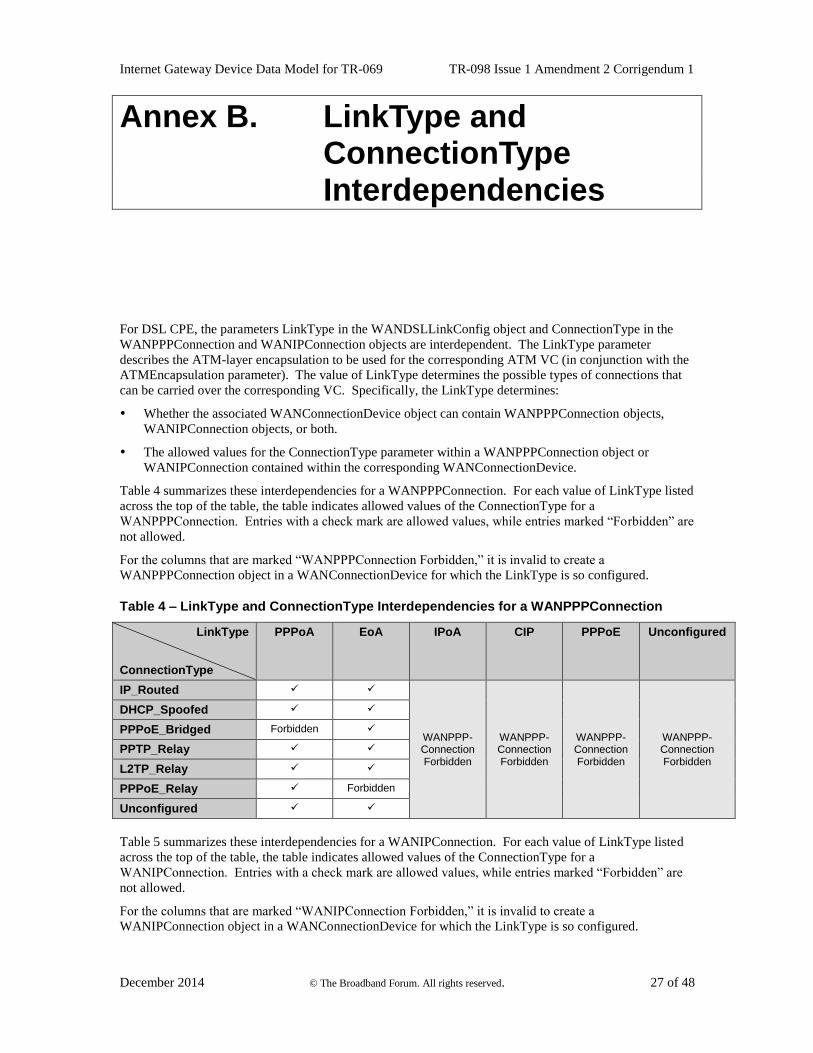
Table 4 summarizes these interdependencies for a WANPPPConnection. For each value of LinkType listed
across the top of the table, the table indicates allowed values of the ConnectionType for a
WANPPPConnection. Entries with a check mark are allowed values, while entries marked “Forbidden” are
not allowed.
For the columns that are marked “WANPPPConnection Forbidden,” it is invalid to create a
WANPPPConnection object in a WANConnectionDevice for which the LinkType is so configured.
Table 4 – LinkType and ConnectionType Interdependencies for a WANPPPConnection
LinkType
ConnectionType
PPPoA EoA IPoA CIP PPPoE Unconfigured
IP_Routed
WANPPP-Connection Forbidden
WANPPP-Connection Forbidden
WANPPP-Connection Forbidden
WANPPP-Connection Forbidden
DHCP_Spoofed
PPPoE_Bridged Forbidden
PPTP_Relay
L2TP_Relay
PPPoE_Relay Forbidden
Unconfigured
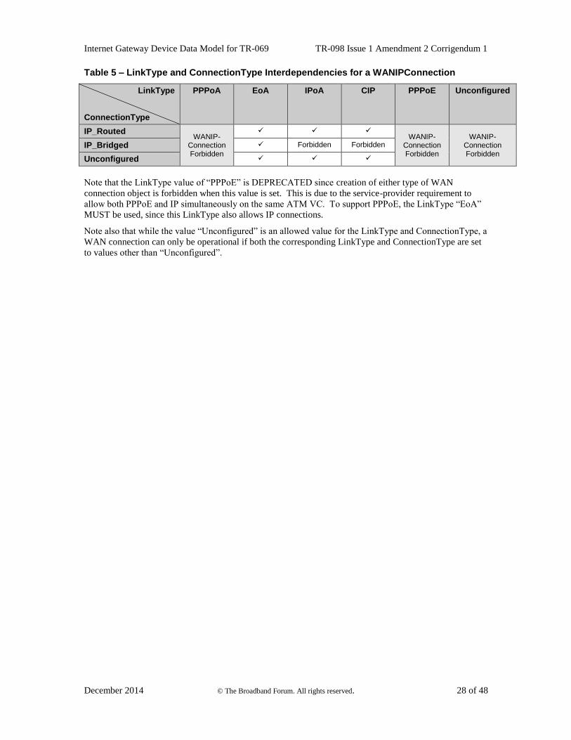
Table 5 summarizes these interdependencies for a WANIPConnection. For each value of LinkType listed
across the top of the table, the table indicates allowed values of the ConnectionType for a
WANIPConnection. Entries with a check mark are allowed values, while entries marked “Forbidden” are
not allowed.
For the columns that are marked “WANIPConnection Forbidden,” it is invalid to create a
WANIPConnection object in a WANConnectionDevice for which the LinkType is so configured.
Internet Gateway Device Data Model for TR-069 TR-098 Issue 1 Amendment 2 Corrigendum 1
December 2014 © The Broadband Forum. All rights reserved. 28 of 48
Table 5 – LinkType and ConnectionType Interdependencies for a WANIPConnection
LinkType
ConnectionType
PPPoA EoA IPoA CIP PPPoE Unconfigured
IP_Routed WANIP-
Connection Forbidden
WANIP-
Connection Forbidden
WANIP-Connection Forbidden
IP_Bridged Forbidden Forbidden
Unconfigured
Note that the LinkType value of “PPPoE” is DEPRECATED since creation of either type of WAN
connection object is forbidden when this value is set. This is due to the service-provider requirement to
allow both PPPoE and IP simultaneously on the same ATM VC. To support PPPoE, the LinkType “EoA”
MUST be used, since this LinkType also allows IP connections.
Note also that while the value “Unconfigured” is an allowed value for the LinkType and ConnectionType, a
WAN connection can only be operational if both the corresponding LinkType and ConnectionType are set
to values other than “Unconfigured”.
Internet Gateway Device Data Model for TR-069 TR-098 Issue 1 Amendment 2 Corrigendum 1
December 2014 © The Broadband Forum. All rights reserved. 29 of 48
Appendix I. Managed bridge configuration in a multi-PVC scenario
This Appendix describes issues to be addressed in configuring a managed bridge in a multi-PVC scenario,
and gives an example configuration.
I.1 Description of scenario
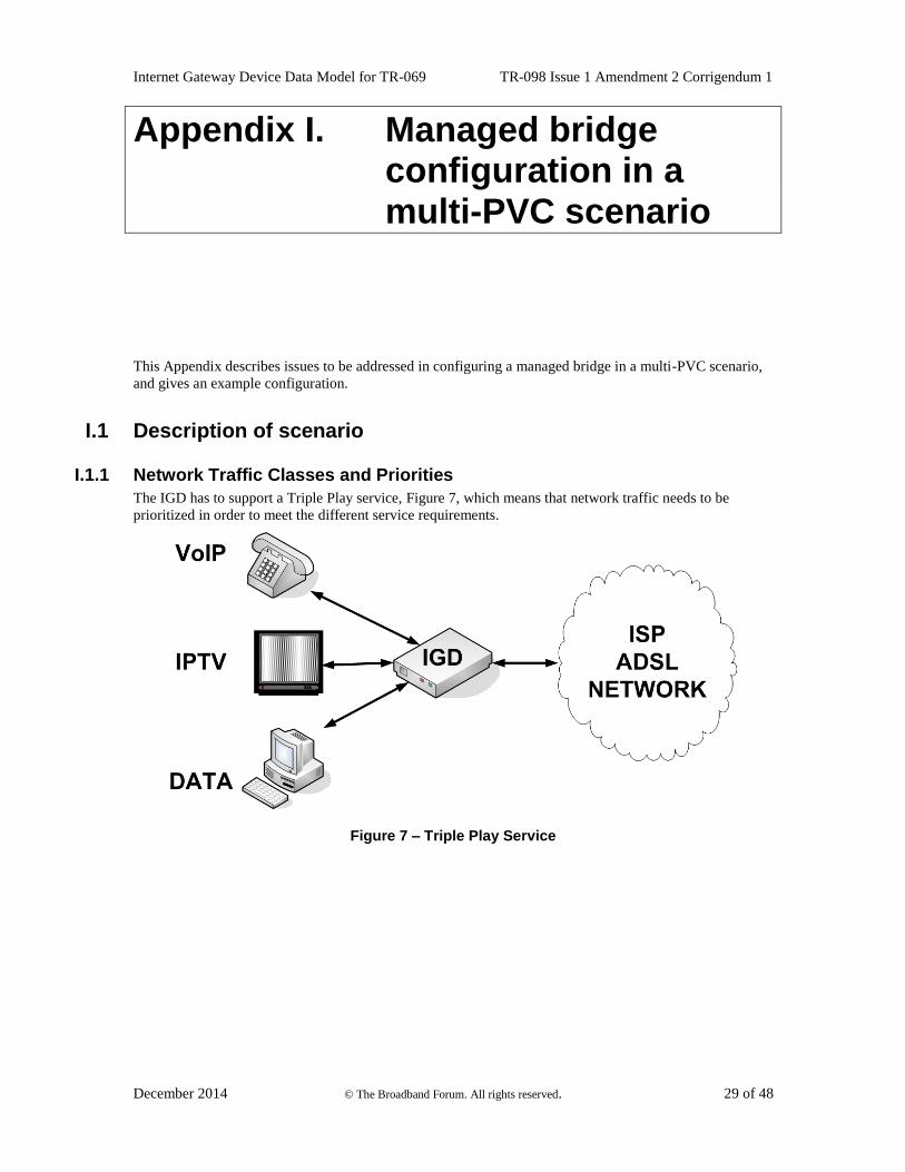
I.1.1 Network Traffic Classes and Priorities
The IGD has to support a Triple Play service, Figure 7, which means that network traffic needs to be
prioritized in order to meet the different service requirements.
Figure 7 – Triple Play Service
Internet Gateway Device Data Model for TR-069 TR-098 Issue 1 Amendment 2 Corrigendum 1
December 2014 © The Broadband Forum. All rights reserved. 30 of 48
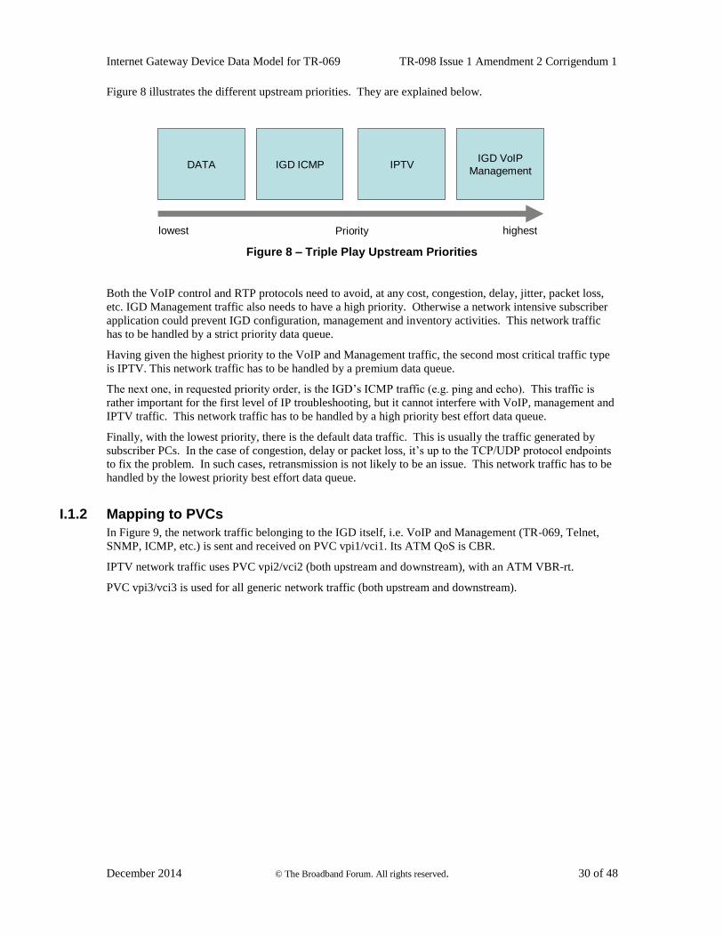
Figure 8 illustrates the different upstream priorities. They are explained below.
Prioritylowest highest
IGD VoIP
ManagementIPTVIGD ICMPDATA
Figure 8 – Triple Play Upstream Priorities
Both the VoIP control and RTP protocols need to avoid, at any cost, congestion, delay, jitter, packet loss,
etc. IGD Management traffic also needs to have a high priority. Otherwise a network intensive subscriber
application could prevent IGD configuration, management and inventory activities. This network traffic
has to be handled by a strict priority data queue.
Having given the highest priority to the VoIP and Management traffic, the second most critical traffic type
is IPTV. This network traffic has to be handled by a premium data queue.
The next one, in requested priority order, is the IGD’s ICMP traffic (e.g. ping and echo). This traffic is
rather important for the first level of IP troubleshooting, but it cannot interfere with VoIP, management and
IPTV traffic. This network traffic has to be handled by a high priority best effort data queue.
Finally, with the lowest priority, there is the default data traffic. This is usually the traffic generated by
subscriber PCs. In the case of congestion, delay or packet loss, it’s up to the TCP/UDP protocol endpoints
to fix the problem. In such cases, retransmission is not likely to be an issue. This network traffic has to be
handled by the lowest priority best effort data queue.
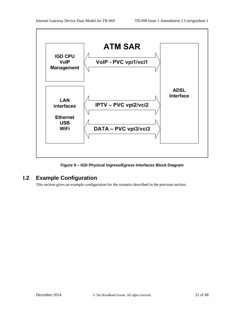
I.1.2 Mapping to PVCs
In Figure 9, the network traffic belonging to the IGD itself, i.e. VoIP and Management (TR-069, Telnet,
SNMP, ICMP, etc.) is sent and received on PVC vpi1/vci1. Its ATM QoS is CBR.
IPTV network traffic uses PVC vpi2/vci2 (both upstream and downstream), with an ATM VBR-rt.
PVC vpi3/vci3 is used for all generic network traffic (both upstream and downstream).
Internet Gateway Device Data Model for TR-069 TR-098 Issue 1 Amendment 2 Corrigendum 1
December 2014 © The Broadband Forum. All rights reserved. 31 of 48
Figure 9 – IGD Physical Ingress/Egress Interfaces Block Diagram
I.2 Example Configuration This section gives an example configuration for the scenario described in the previous section.
Internet Gateway Device Data Model for TR-069 TR-098 Issue 1 Amendment 2 Corrigendum 1
December 2014 © The Broadband Forum. All rights reserved. 32 of 48
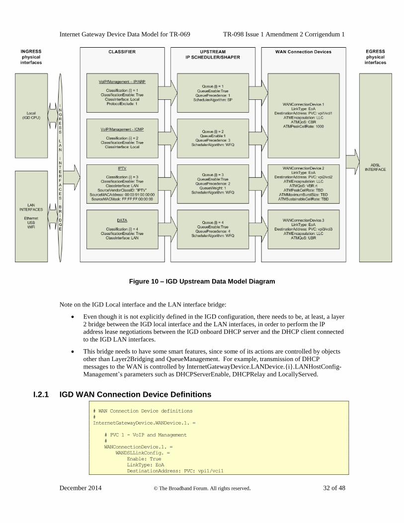
Figure 10 – IGD Upstream Data Model Diagram
Note on the IGD Local interface and the LAN interface bridge:
Even though it is not explicitly defined in the IGD configuration, there needs to be, at least, a layer
2 bridge between the IGD local interface and the LAN interfaces, in order to perform the lP
address lease negotiations between the IGD onboard DHCP server and the DHCP client connected
to the IGD LAN interfaces.
This bridge needs to have some smart features, since some of its actions are controlled by objects
other than Layer2Bridging and QueueManagement. For example, transmission of DHCP
messages to the WAN is controlled by InternetGatewayDevice.LANDevice.{i}.LANHostConfig-
Management’s parameters such as DHCPServerEnable, DHCPRelay and LocallyServed.
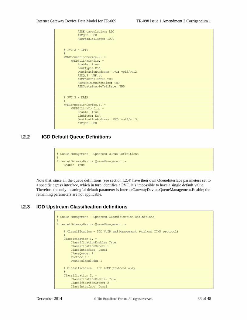
I.2.1 IGD WAN Connection Device Definitions
# WAN Connection Device definitions
#
InternetGatewayDevice.WANDevice.1. =
# PVC 1 - VoIP and Management
#
WANConnectionDevice.1. =
WANDSLLinkConfig. =
Enable: True
LinkType: EoA
DestinationAddress: PVC: vpi1/vci1
Internet Gateway Device Data Model for TR-069 TR-098 Issue 1 Amendment 2 Corrigendum 1
December 2014 © The Broadband Forum. All rights reserved. 33 of 48
ATMEncapsulation: LLC
ATMQoS: CBR
ATMPeakCellRate: 1000
# PVC 2 - IPTV
#
WANConnectionDevice.2. =
WANDSLLinkConfig. =
Enable: True
LinkType: EoA
DestinationAddress: PVC: vpi2/vci2
ATMQoS: VBR.rt
ATMPeakCellRate: TBD
ATMMaximumBurstSize: TBD
ATMSustainableCellRate: TBD
# PVC 3 - DATA
#
WANConnectionDevice.3. =
WANDSLLinkConfig. =
Enable: True
LinkType: EoA
DestinationAddress: PVC: vpi3/vci3
ATMQoS: UBR
I.2.2 IGD Default Queue Definitions
# Queue Management – Upstream Queue Definitions
#
InternetGatewayDevice.QueueManagement. =
Enable: True
Note that, since all the queue definitions (see section I.2.4) have their own QueueInterface parameters set to
a specific egress interface, which in turn identifies a PVC, it’s impossible to have a single default value.
Therefore the only meaningful default parameter is InternetGatewayDevice.QueueManagement.Enable; the
remaining parameters are not applicable.
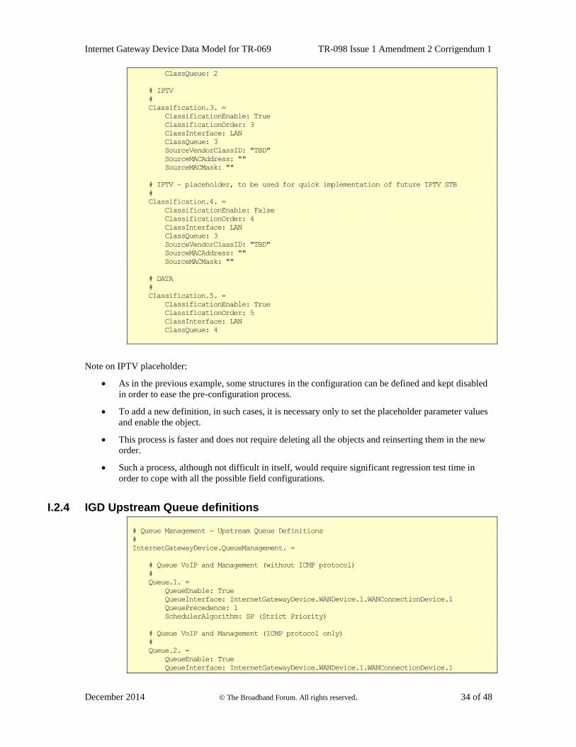
I.2.3 IGD Upstream Classification definitions
# Queue Management - Upstream Classification Definitions
#
InternetGatewayDevice.QueueManagement. =
# Classification – IGD VoIP and Management (without ICMP protocol)
#
Classification.1. =
ClassificationEnable: True
ClassificationOrder: 1
ClassInterface: Local
ClassQueue: 1
Protocol: 1
ProtocolExclude: 1
# Classification – IGD ICMP protocol only
#
Classification.2. =
ClassificationEnable: True
ClassificationOrder: 2
ClassInterface: Local
Internet Gateway Device Data Model for TR-069 TR-098 Issue 1 Amendment 2 Corrigendum 1
December 2014 © The Broadband Forum. All rights reserved. 34 of 48
ClassQueue: 2
# IPTV
#
Classification.3. =
ClassificationEnable: True
ClassificationOrder: 3
ClassInterface: LAN
ClassQueue: 3
SourceVendorClassID: "TBD"
SourceMACAddress: ""
SourceMACMask: ""
# IPTV – placeholder, to be used for quick implementation of future IPTV STB
#
Classification.4. =
ClassificationEnable: False
ClassificationOrder: 4
ClassInterface: LAN
ClassQueue: 3
SourceVendorClassID: "TBD"
SourceMACAddress: ""
SourceMACMask: ""
# DATA
#
Classification.5. =
ClassificationEnable: True
ClassificationOrder: 5
ClassInterface: LAN
ClassQueue: 4
Note on IPTV placeholder:
As in the previous example, some structures in the configuration can be defined and kept disabled
in order to ease the pre-configuration process.
To add a new definition, in such cases, it is necessary only to set the placeholder parameter values
and enable the object.
This process is faster and does not require deleting all the objects and reinserting them in the new
order.
Such a process, although not difficult in itself, would require significant regression test time in
order to cope with all the possible field configurations.
I.2.4 IGD Upstream Queue definitions
# Queue Management – Upstream Queue Definitions
#
InternetGatewayDevice.QueueManagement. =
# Queue VoIP and Management (without ICMP protocol)
#
Queue.1. =
QueueEnable: True
QueueInterface: InternetGatewayDevice.WANDevice.1.WANConnectionDevice.1
QueuePrecedence: 1
SchedulerAlgorithm: SP (Strict Priority)
# Queue VoIP and Management (ICMP protocol only)
#
Queue.2. =
QueueEnable: True
QueueInterface: InternetGatewayDevice.WANDevice.1.WANConnectionDevice.1
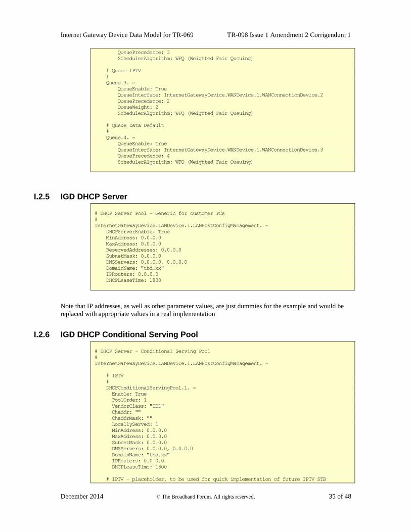
Internet Gateway Device Data Model for TR-069 TR-098 Issue 1 Amendment 2 Corrigendum 1
December 2014 © The Broadband Forum. All rights reserved. 35 of 48
QueuePrecedence: 3
SchedulerAlgorithm: WFQ (Weighted Fair Queuing)
# Queue IPTV
#
Queue.3. =
QueueEnable: True
QueueInterface: InternetGatewayDevice.WANDevice.1.WANConnectionDevice.2
QueuePrecedence: 2
QueueWeight: 2
SchedulerAlgorithm: WFQ (Weighted Fair Queuing)
# Queue Data Default
#
Queue.4. =
QueueEnable: True
QueueInterface: InternetGatewayDevice.WANDevice.1.WANConnectionDevice.3
QueuePrecedence: 4
SchedulerAlgorithm: WFQ (Weighted Fair Queuing)
I.2.5 IGD DHCP Server
# DHCP Server Pool – Generic for customer PCs
#
InternetGatewayDevice.LANDevice.1.LANHostConfigManagement. =
DHCPServerEnable: True
MinAddress: 0.0.0.0
MaxAddress: 0.0.0.0
ReservedAddresses: 0.0.0.0
SubnetMask: 0.0.0.0
DNSServers: 0.0.0.0, 0.0.0.0
DomainName: "tbd.xx"
IPRouters: 0.0.0.0
DHCPLeaseTime: 1800
Note that IP addresses, as well as other parameter values, are just dummies for the example and would be
replaced with appropriate values in a real implementation
I.2.6 IGD DHCP Conditional Serving Pool
# DHCP Server – Conditional Serving Pool
#
InternetGatewayDevice.LANDevice.1.LANHostConfigManagement. =
# IPTV
#
DHCPConditionalServingPool.1. =
Enable: True
PoolOrder: 1
VendorClass: "TBD"
Chaddr: ""
ChaddrMask: ""
LocallyServed: 1
MinAddress: 0.0.0.0
MaxAddress: 0.0.0.0
SubnetMask: 0.0.0.0
DNSServers: 0.0.0.0, 0.0.0.0
DomainName: "tbd.xx"
IPRouters: 0.0.0.0
DHCPLeaseTime: 1800
# IPTV – placeholder, to be used for quick implementation of future IPTV STB
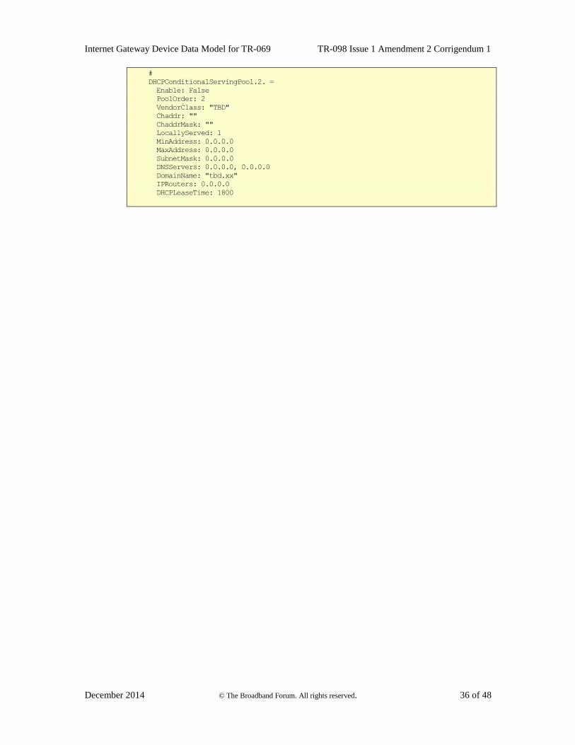
Internet Gateway Device Data Model for TR-069 TR-098 Issue 1 Amendment 2 Corrigendum 1
December 2014 © The Broadband Forum. All rights reserved. 36 of 48
#
DHCPConditionalServingPool.2. =
Enable: False
PoolOrder: 2
VendorClass: "TBD"
Chaddr: ""
ChaddrMask: ""
LocallyServed: 1
MinAddress: 0.0.0.0
MaxAddress: 0.0.0.0
SubnetMask: 0.0.0.0
DNSServers: 0.0.0.0, 0.0.0.0
DomainName: "tbd.xx"
IPRouters: 0.0.0.0
DHCPLeaseTime: 1800
Internet Gateway Device Data Model for TR-069 TR-098 Issue 1 Amendment 2 Corrigendum 1
December 2014 © The Broadband Forum. All rights reserved. 37 of 48
Appendix II. Use of the Bridging Objects for VLAN Tagging
In the case of an Ethernet WAN Interface or a VDSL2 WAN Interface based on PTM-EFM, 802.1Q
Tagging can be used to tag egress traffic on the WAN interface. This choice enables a multi-VLAN
architecture in order to deploy a multi-service configuration (high speed Internet, VoIP, Video Phone,
IPTV, etc.), where one VLAN or a group of VLANs are associated with each service.
If 802.1Q tagging on the WAN interface is used, it is necessary to have a way to associate LAN incoming
802.1Q tagged or untagged traffic or internally generated traffic (PPPoE, IPoE connections) to the egress
(and vice-versa). The solution is to apply coherent bridging rules.
Regarding different traffic bridging rules, the possible cases characterized are the following:
Tagged LAN to tagged WAN traffic (pure VLAN bridging), with VLAN ID translation as a
special case
Untagged LAN to tagged WAN traffic
Internally generated to tagged WAN traffic
To better understand the different cases, refer to Figure 11 and to the following examples.
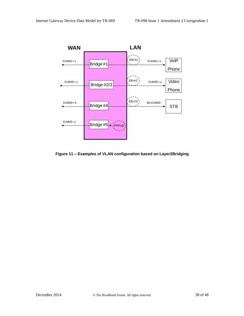
Internet Gateway Device Data Model for TR-069 TR-098 Issue 1 Amendment 2 Corrigendum 1
December 2014 © The Broadband Forum. All rights reserved. 38 of 48
WAN
Eth #1
Eth #2
VoIP
Phone
Video
Phone
STB
Eth #3
VLANID = x
VLANID = y
VLANID = x
VLANID = z
VLANID = k No VLANID
PPPoE
VLANID = jBridge #5
Bridge #4
Bridge #2/3
Bridge #1
LAN
Figure 11 – Examples of VLAN configuration based on Layer2Bridging
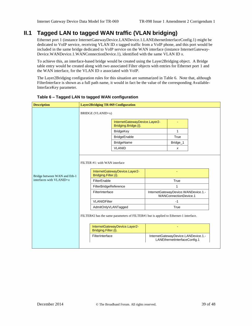
Internet Gateway Device Data Model for TR-069 TR-098 Issue 1 Amendment 2 Corrigendum 1
December 2014 © The Broadband Forum. All rights reserved. 39 of 48
II.1 Tagged LAN to tagged WAN traffic (VLAN bridging) Ethernet port 1 (instance InternetGatewayDevice.LANDevice.1.LANEthernetInterfaceConfig.1) might be
dedicated to VoIP service, receiving VLAN ID x tagged traffic from a VoIP phone, and this port would be
included in the same bridge dedicated to VoIP service on the WAN interface (instance InternetGateway-
Device.WANDevice.1.WANConnectionDevice.1), identified with the same VLAN ID x.
To achieve this, an interface-based bridge would be created using the Layer2Bridging object. A Bridge
table entry would be created along with two associated Filter objects with entries for Ethernet port 1 and
the WAN interface, for the VLAN ID x associated with VoIP.
The Layer2Bridging configuration rules for this situation are summarized in Table 6. Note that, although
FilterInterface is shown as a full path name, it would in fact be the value of the corresponding Available-
InterfaceKey parameter.
Table 6 – Tagged LAN to tagged WAN configuration
Description Layer2Bridging TR-069 Configuration
Bridge between WAN and Eth-1
interfaces with VLANID=x
BRIDGE (VLANID=x)
InternetGatewayDevice.Layer2-Bridging.Bridge.{i}.
-
BridgeKey 1
BridgeEnable True
BridgeName Bridge_1
VLANID x
FILTER #1: with WAN interface
InternetGatewayDevice.Layer2-Bridging.Filter.{i}.
-
FilterEnable True
FilterBridgeReference 1
FilterInterface InternetGatewayDevice.WANDevice.1.-WANConnectionDevice.1
VLANIDFilter -1
AdmitOnlyVLANTagged True
FILTER#2 has the same parameters of FILTER#1 but is applied to Ethernet-1 interface.
InternetGatewayDevice.Layer2-Bridging.Filter.{i}.
-
FilterInterface InternetGatewayDevice.LANDevice.1.-LANEthernetInterfaceConfig.1
Internet Gateway Device Data Model for TR-069 TR-098 Issue 1 Amendment 2 Corrigendum 1
December 2014 © The Broadband Forum. All rights reserved. 40 of 48
II.2 Tagged LAN to tagged WAN traffic (special case with VLAN ID translation) Ethernet port 2 (instance InternetGatewayDevice.LANDevice.1.LANEthernetInterfaceConfig.2) might be
dedicated to Video Phone service, receiving VLAN ID y tagged traffic from a Video phone, and this port
would be included in the same bridge dedicated to Video Phone service on the WAN interface (instance
InternetGatewayDevice.WANDevice.1.WANConnectionDevice.1), identified by a different VLAN ID
(VLAN ID z). In this case a VLAN translation needs to be performed.
To achieve this, a pair of unidirectional interface-based bridges would be created using the Layer2Bridging
object, one for LAN-to-WAN traffic and the other for WAN-to-LAN traffic. For each bridge, a Bridge
table entry would be created along with two associated Filter object entries for {Ethernet port 2/VLAN ID
y} and {WAN interface/VLAN ID z}, to identify ingress frames. After that, in order to re-mark the egress
frames appropriately, a Marking object would also be created for each bridge, with Marking table entries
for the egress interfaces: {Ethernet port 2/VLAN ID y} and {WAN interface/VLAN ID z}.
Note – if a single bi-directional bridge had been used, then in order to define the VLAN Member
Sets correctly Filter entries for both VLAN ID y and VLAN ID z would be needed for each of the
bridge interfaces. This would permit ingress of VLAN ID z packets to the LAN interface, and of
VLAN ID y packets to the WAN interface, which would be incorrect behavior. With the two-
bridge approach, the LAN-to-WAN bridge bridges only VLAN ID y packets (marked z on egress),
and the WAN-to-LAN bridge bridges only VLAN ID z packets (marked y on egress).
The Layer2Bridging configuration rules for this situation are summarized in Table 7 (LAN-to-WAN) and
Table 8 (WAN-to-LAN). Note that, although FilterInterface and MarkingInterface are shown as full path
names, they would in fact be the values of the corresponding AvailableInterfaceKey parameters.
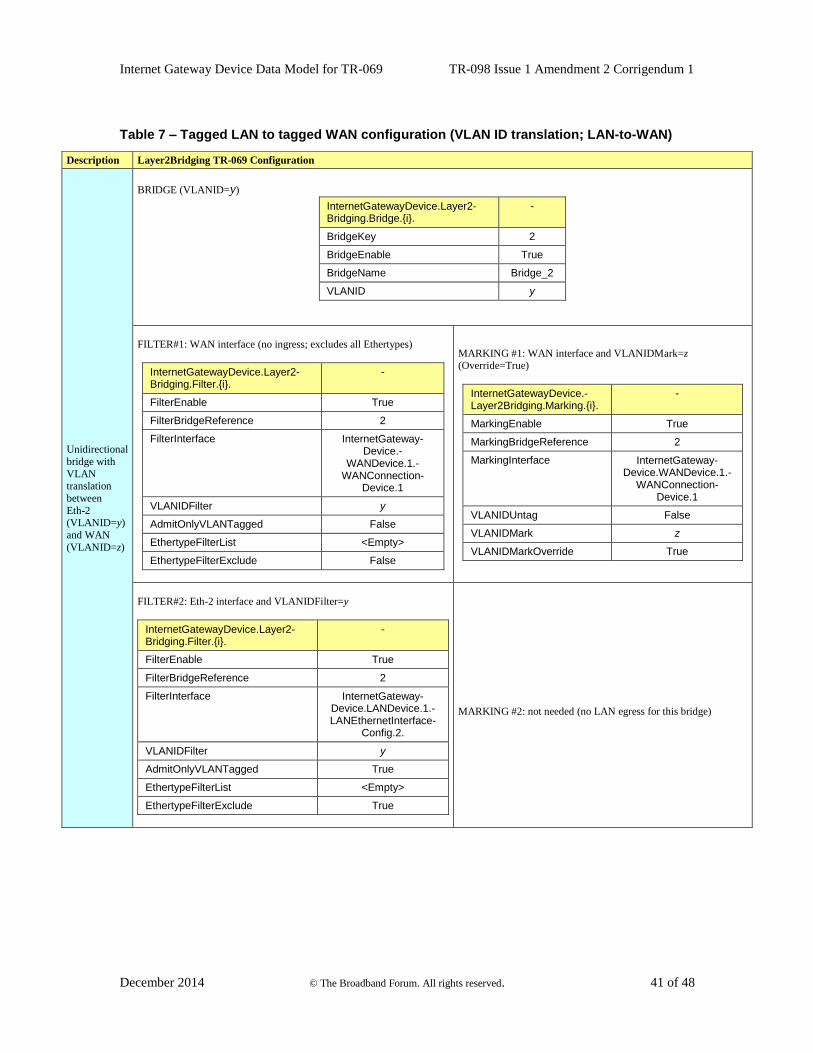
Internet Gateway Device Data Model for TR-069 TR-098 Issue 1 Amendment 2 Corrigendum 1
December 2014 © The Broadband Forum. All rights reserved. 41 of 48
Table 7 – Tagged LAN to tagged WAN configuration (VLAN ID translation; LAN-to-WAN)
Description Layer2Bridging TR-069 Configuration
Unidirectional
bridge with
VLAN translation
between
Eth-2 (VLANID=y)
and WAN
(VLANID=z)
BRIDGE (VLANID=y)
InternetGatewayDevice.Layer2-Bridging.Bridge.{i}.
-
BridgeKey 2
BridgeEnable True
BridgeName Bridge_2
VLANID y
FILTER#1: WAN interface (no ingress; excludes all Ethertypes)
InternetGatewayDevice.Layer2-Bridging.Filter.{i}.
-
FilterEnable True
FilterBridgeReference 2
FilterInterface InternetGateway-Device.-
WANDevice.1.-WANConnection-
Device.1
VLANIDFilter y
AdmitOnlyVLANTagged False
EthertypeFilterList <Empty>
EthertypeFilterExclude False
MARKING #1: WAN interface and VLANIDMark=z (Override=True)
InternetGatewayDevice.-Layer2Bridging.Marking.{i}.
-
MarkingEnable True
MarkingBridgeReference 2
MarkingInterface InternetGateway-Device.WANDevice.1.-
WANConnection-Device.1
VLANIDUntag False
VLANIDMark z
VLANIDMarkOverride True
FILTER#2: Eth-2 interface and VLANIDFilter=y
InternetGatewayDevice.Layer2-Bridging.Filter.{i}.
-
FilterEnable True
FilterBridgeReference 2
FilterInterface InternetGateway-Device.LANDevice.1.-LANEthernetInterface-
Config.2.
VLANIDFilter y
AdmitOnlyVLANTagged True
EthertypeFilterList <Empty>
EthertypeFilterExclude True
MARKING #2: not needed (no LAN egress for this bridge)
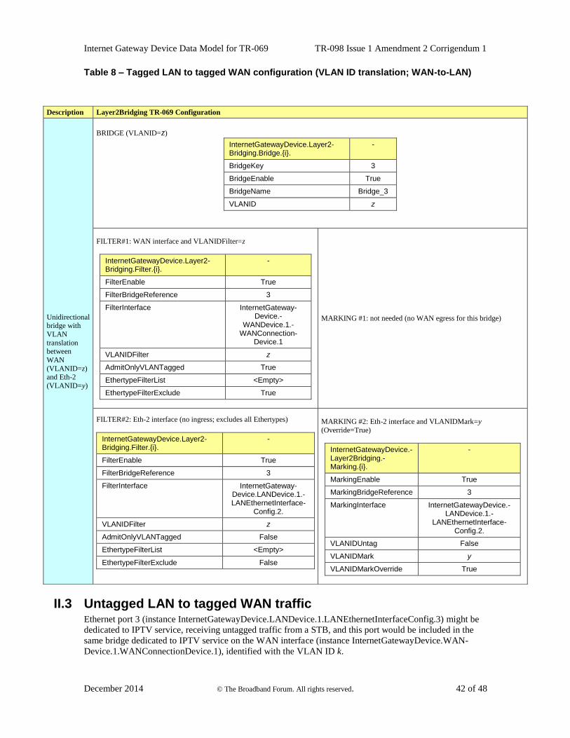
Internet Gateway Device Data Model for TR-069 TR-098 Issue 1 Amendment 2 Corrigendum 1
December 2014 © The Broadband Forum. All rights reserved. 42 of 48
Table 8 – Tagged LAN to tagged WAN configuration (VLAN ID translation; WAN-to-LAN)
II.3 Untagged LAN to tagged WAN traffic Ethernet port 3 (instance InternetGatewayDevice.LANDevice.1.LANEthernetInterfaceConfig.3) might be
dedicated to IPTV service, receiving untagged traffic from a STB, and this port would be included in the
same bridge dedicated to IPTV service on the WAN interface (instance InternetGatewayDevice.WAN-
Device.1.WANConnectionDevice.1), identified with the VLAN ID k.
Description Layer2Bridging TR-069 Configuration
Unidirectional bridge with
VLAN
translation between
WAN
(VLANID=z) and Eth-2
(VLANID=y)
BRIDGE (VLANID=z)
InternetGatewayDevice.Layer2-Bridging.Bridge.{i}.
-
BridgeKey 3
BridgeEnable True
BridgeName Bridge_3
VLANID z
FILTER#1: WAN interface and VLANIDFilter=z
InternetGatewayDevice.Layer2-Bridging.Filter.{i}.
-
FilterEnable True
FilterBridgeReference 3
FilterInterface InternetGateway-Device.-
WANDevice.1.-WANConnection-
Device.1
VLANIDFilter z
AdmitOnlyVLANTagged True
EthertypeFilterList <Empty>
EthertypeFilterExclude True
MARKING #1: not needed (no WAN egress for this bridge)
FILTER#2: Eth-2 interface (no ingress; excludes all Ethertypes)
InternetGatewayDevice.Layer2-Bridging.Filter.{i}.
-
FilterEnable True
FilterBridgeReference 3
FilterInterface InternetGateway-Device.LANDevice.1.-LANEthernetInterface-
Config.2.
VLANIDFilter z
AdmitOnlyVLANTagged False
EthertypeFilterList <Empty>
EthertypeFilterExclude False
MARKING #2: Eth-2 interface and VLANIDMark=y
(Override=True)
InternetGatewayDevice.-Layer2Bridging.-Marking.{i}.
-
MarkingEnable True
MarkingBridgeReference 3
MarkingInterface InternetGatewayDevice.-LANDevice.1.-
LANEthernetInterface-Config.2.
VLANIDUntag False
VLANIDMark y
VLANIDMarkOverride True
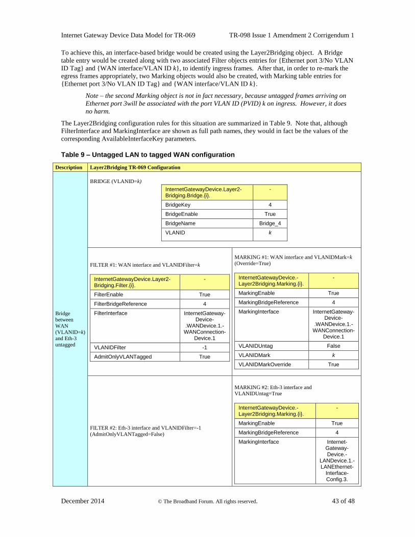
Internet Gateway Device Data Model for TR-069 TR-098 Issue 1 Amendment 2 Corrigendum 1
December 2014 © The Broadband Forum. All rights reserved. 43 of 48
To achieve this, an interface-based bridge would be created using the Layer2Bridging object. A Bridge
table entry would be created along with two associated Filter objects entries for {Ethernet port 3/No VLAN
ID Tag} and {WAN interface/VLAN ID k}, to identify ingress frames. After that, in order to re-mark the
egress frames appropriately, two Marking objects would also be created, with Marking table entries for
{Ethernet port 3/No VLAN ID Tag} and {WAN interface/VLAN ID k}.
Note – the second Marking object is not in fact necessary, because untagged frames arriving on
Ethernet port 3will be associated with the port VLAN ID (PVID) k on ingress. However, it does
no harm.
The Layer2Bridging configuration rules for this situation are summarized in Table 9. Note that, although
FilterInterface and MarkingInterface are shown as full path names, they would in fact be the values of the
corresponding AvailableInterfaceKey parameters.
Table 9 – Untagged LAN to tagged WAN configuration
Description Layer2Bridging TR-069 Configuration
Bridge
between
WAN (VLANID=k)
and Eth-3
untagged
BRIDGE (VLANID=k)
InternetGatewayDevice.Layer2-Bridging.Bridge.{i}.
-
BridgeKey 4
BridgeEnable True
BridgeName Bridge_4
VLANID k
FILTER #1: WAN interface and VLANIDFilter=k
InternetGatewayDevice.Layer2-Bridging.Filter.{i}.
-
FilterEnable True
FilterBridgeReference 4
FilterInterface InternetGateway-Device-
.WANDevice.1.-WANConnection-
Device.1
VLANIDFilter -1
AdmitOnlyVLANTagged True
MARKING #1: WAN interface and VLANIDMark=k (Override=True)
InternetGatewayDevice.-Layer2Bridging.Marking.{i}.
-
MarkingEnable True
MarkingBridgeReference 4
MarkingInterface InternetGateway-Device-
.WANDevice.1.-WANConnection-
Device.1
VLANIDUntag False
VLANIDMark k
VLANIDMarkOverride True
FILTER #2: Eth-3 interface and VLANIDFilter=-1
(AdmitOnlyVLANTagged=False)
MARKING #2: Eth-3 interface and VLANIDUntag=True
InternetGatewayDevice.-Layer2Bridging.Marking.{i}.
-
MarkingEnable True
MarkingBridgeReference 4
MarkingInterface Internet-Gateway-Device.-
LANDevice.1.-LANEthernet-
Interface-Config.3.
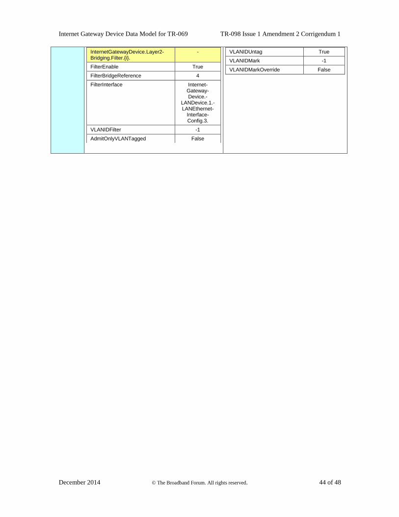
Internet Gateway Device Data Model for TR-069 TR-098 Issue 1 Amendment 2 Corrigendum 1
December 2014 © The Broadband Forum. All rights reserved. 44 of 48
InternetGatewayDevice.Layer2-Bridging.Filter.{i}.
-
FilterEnable True
FilterBridgeReference 4
FilterInterface Internet-Gateway-Device.-
LANDevice.1.-LANEthernet-
Interface-Config.3.
VLANIDFilter -1
AdmitOnlyVLANTagged False
VLANIDUntag True
VLANIDMark -1
VLANIDMarkOverride False
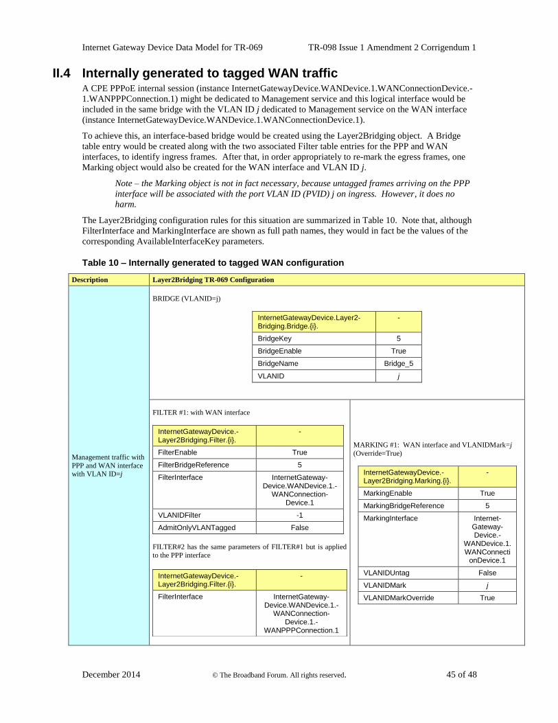
Internet Gateway Device Data Model for TR-069 TR-098 Issue 1 Amendment 2 Corrigendum 1
December 2014 © The Broadband Forum. All rights reserved. 45 of 48
II.4 Internally generated to tagged WAN traffic A CPE PPPoE internal session (instance InternetGatewayDevice.WANDevice.1.WANConnectionDevice.-
1.WANPPPConnection.1) might be dedicated to Management service and this logical interface would be
included in the same bridge with the VLAN ID j dedicated to Management service on the WAN interface
(instance InternetGatewayDevice.WANDevice.1.WANConnectionDevice.1).
To achieve this, an interface-based bridge would be created using the Layer2Bridging object. A Bridge
table entry would be created along with the two associated Filter table entries for the PPP and WAN
interfaces, to identify ingress frames. After that, in order appropriately to re-mark the egress frames, one
Marking object would also be created for the WAN interface and VLAN ID j.
Note – the Marking object is not in fact necessary, because untagged frames arriving on the PPP
interface will be associated with the port VLAN ID (PVID) j on ingress. However, it does no
harm.
The Layer2Bridging configuration rules for this situation are summarized in Table 10. Note that, although
FilterInterface and MarkingInterface are shown as full path names, they would in fact be the values of the
corresponding AvailableInterfaceKey parameters.
Table 10 – Internally generated to tagged WAN configuration
Description Layer2Bridging TR-069 Configuration
Management traffic with
PPP and WAN interface with VLAN ID=j
BRIDGE (VLANID=j)
InternetGatewayDevice.Layer2-Bridging.Bridge.{i}.
-
BridgeKey 5
BridgeEnable True
BridgeName Bridge_5
VLANID j
FILTER #1: with WAN interface
InternetGatewayDevice.-Layer2Bridging.Filter.{i}.
-
FilterEnable True
FilterBridgeReference 5
FilterInterface InternetGateway-Device.WANDevice.1.-
WANConnection-Device.1
VLANIDFilter -1
AdmitOnlyVLANTagged False
FILTER#2 has the same parameters of FILTER#1 but is applied
to the PPP interface
InternetGatewayDevice.-Layer2Bridging.Filter.{i}.
-
FilterInterface InternetGateway-Device.WANDevice.1.-
WANConnection-Device.1.-
WANPPPConnection.1
MARKING #1: WAN interface and VLANIDMark=j
(Override=True)
InternetGatewayDevice.-Layer2Bridging.Marking.{i}.
-
MarkingEnable True
MarkingBridgeReference 5
MarkingInterface Internet-Gateway-Device.-
WANDevice.1.WANConnecti
onDevice.1
VLANIDUntag False
VLANIDMark j
VLANIDMarkOverride True
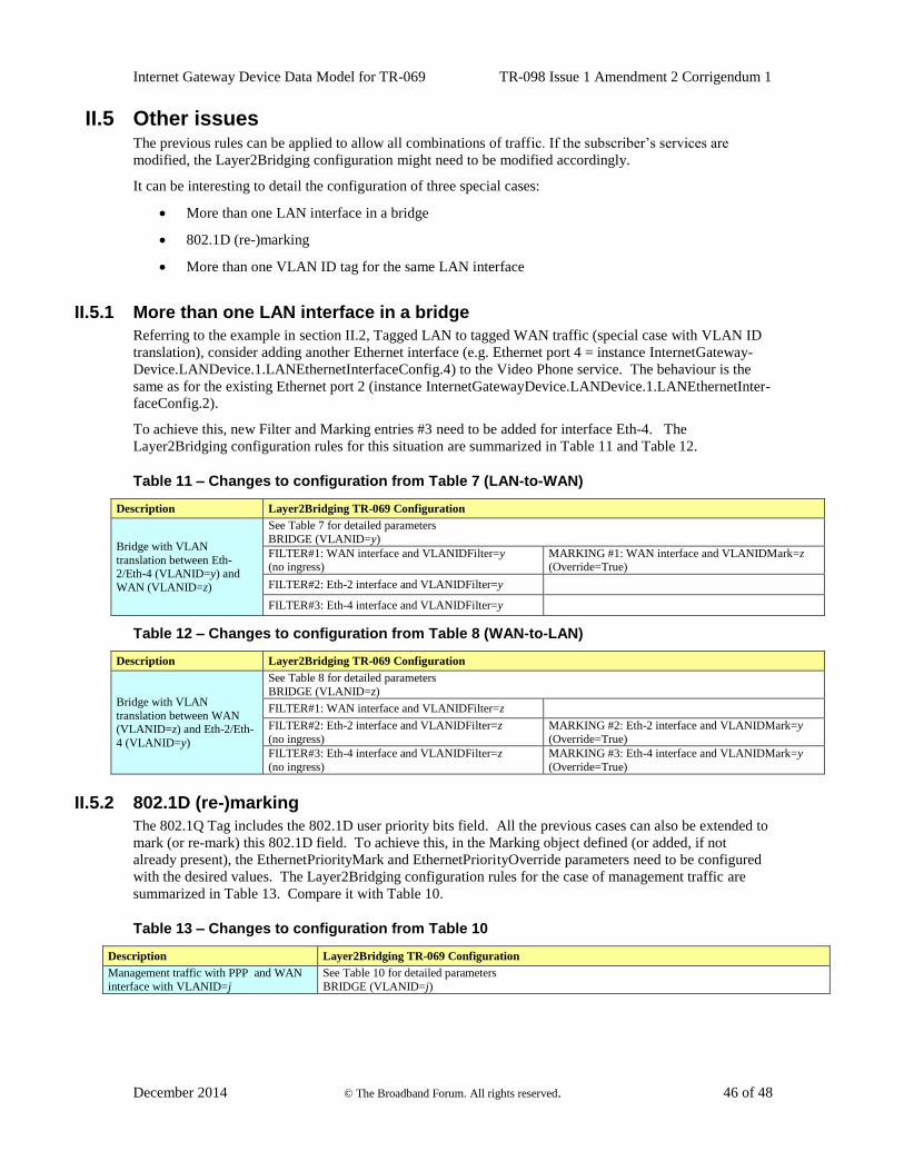
Internet Gateway Device Data Model for TR-069 TR-098 Issue 1 Amendment 2 Corrigendum 1
December 2014 © The Broadband Forum. All rights reserved. 46 of 48
II.5 Other issues The previous rules can be applied to allow all combinations of traffic. If the subscriber’s services are
modified, the Layer2Bridging configuration might need to be modified accordingly.
It can be interesting to detail the configuration of three special cases:
More than one LAN interface in a bridge
802.1D (re-)marking
More than one VLAN ID tag for the same LAN interface
II.5.1 More than one LAN interface in a bridge
Referring to the example in section II.2, Tagged LAN to tagged WAN traffic (special case with VLAN ID
translation), consider adding another Ethernet interface (e.g. Ethernet port 4 = instance InternetGateway-
Device.LANDevice.1.LANEthernetInterfaceConfig.4) to the Video Phone service. The behaviour is the
same as for the existing Ethernet port 2 (instance InternetGatewayDevice.LANDevice.1.LANEthernetInter-
faceConfig.2).
To achieve this, new Filter and Marking entries #3 need to be added for interface Eth-4. The
Layer2Bridging configuration rules for this situation are summarized in Table 11 and Table 12.
Table 11 – Changes to configuration from Table 7 (LAN-to-WAN)
Description Layer2Bridging TR-069 Configuration
Bridge with VLAN
translation between Eth-2/Eth-4 (VLANID=y) and
WAN (VLANID=z)
See Table 7 for detailed parameters
BRIDGE (VLANID=y)
FILTER#1: WAN interface and VLANIDFilter=y (no ingress)
MARKING #1: WAN interface and VLANIDMark=z (Override=True)
FILTER#2: Eth-2 interface and VLANIDFilter=y
FILTER#3: Eth-4 interface and VLANIDFilter=y
Table 12 – Changes to configuration from Table 8 (WAN-to-LAN)
Description Layer2Bridging TR-069 Configuration
Bridge with VLAN
translation between WAN (VLANID=z) and Eth-2/Eth-
4 (VLANID=y)
See Table 8 for detailed parameters
BRIDGE (VLANID=z)
FILTER#1: WAN interface and VLANIDFilter=z
FILTER#2: Eth-2 interface and VLANIDFilter=z
(no ingress)
MARKING #2: Eth-2 interface and VLANIDMark=y
(Override=True)
FILTER#3: Eth-4 interface and VLANIDFilter=z
(no ingress)
MARKING #3: Eth-4 interface and VLANIDMark=y
(Override=True)
II.5.2 802.1D (re-)marking
The 802.1Q Tag includes the 802.1D user priority bits field. All the previous cases can also be extended to
mark (or re-mark) this 802.1D field. To achieve this, in the Marking object defined (or added, if not
already present), the EthernetPriorityMark and EthernetPriorityOverride parameters need to be configured
with the desired values. The Layer2Bridging configuration rules for the case of management traffic are
summarized in Table 13. Compare it with Table 10.
Table 13 – Changes to configuration from Table 10
Description Layer2Bridging TR-069 Configuration
Management traffic with PPP and WAN
interface with VLANID=j
See Table 10 for detailed parameters
BRIDGE (VLANID=j)
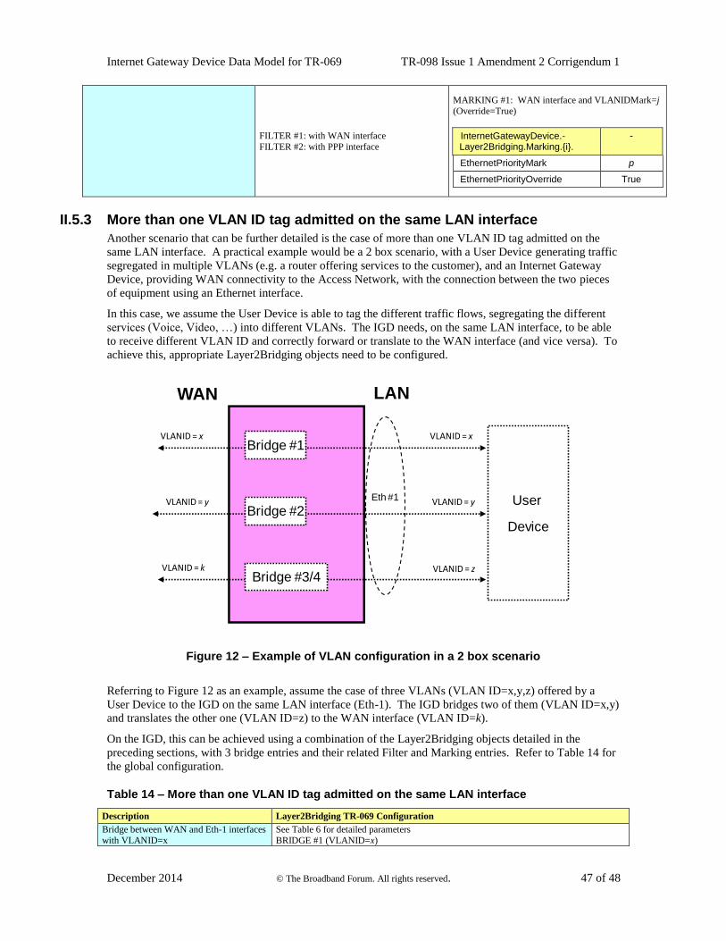
Internet Gateway Device Data Model for TR-069 TR-098 Issue 1 Amendment 2 Corrigendum 1
December 2014 © The Broadband Forum. All rights reserved. 47 of 48
FILTER #1: with WAN interface
FILTER #2: with PPP interface
MARKING #1: WAN interface and VLANIDMark=j
(Override=True)
InternetGatewayDevice.-Layer2Bridging.Marking.{i}.
-
EthernetPriorityMark p
EthernetPriorityOverride True
II.5.3 More than one VLAN ID tag admitted on the same LAN interface
Another scenario that can be further detailed is the case of more than one VLAN ID tag admitted on the
same LAN interface. A practical example would be a 2 box scenario, with a User Device generating traffic
segregated in multiple VLANs (e.g. a router offering services to the customer), and an Internet Gateway
Device, providing WAN connectivity to the Access Network, with the connection between the two pieces
of equipment using an Ethernet interface.
In this case, we assume the User Device is able to tag the different traffic flows, segregating the different
services (Voice, Video, …) into different VLANs. The IGD needs, on the same LAN interface, to be able
to receive different VLAN ID and correctly forward or translate to the WAN interface (and vice versa). To
achieve this, appropriate Layer2Bridging objects need to be configured.
WAN
Eth #1 User
Device
VLANID = x
VLANID = y
VLANID = x
VLANID = y
VLANID = kBridge #3/4
Bridge #2
Bridge #1
LAN
VLANID = z
Figure 12 – Example of VLAN configuration in a 2 box scenario
Referring to Figure 12 as an example, assume the case of three VLANs (VLAN ID=x,y,z) offered by a
User Device to the IGD on the same LAN interface (Eth-1). The IGD bridges two of them (VLAN ID=x,y)
and translates the other one (VLAN ID=z) to the WAN interface (VLAN ID=k).
On the IGD, this can be achieved using a combination of the Layer2Bridging objects detailed in the
preceding sections, with 3 bridge entries and their related Filter and Marking entries. Refer to Table 14 for
the global configuration.
Table 14 – More than one VLAN ID tag admitted on the same LAN interface
Description Layer2Bridging TR-069 Configuration
Bridge between WAN and Eth-1 interfaces
with VLANID=x
See Table 6 for detailed parameters
BRIDGE #1 (VLANID=x)
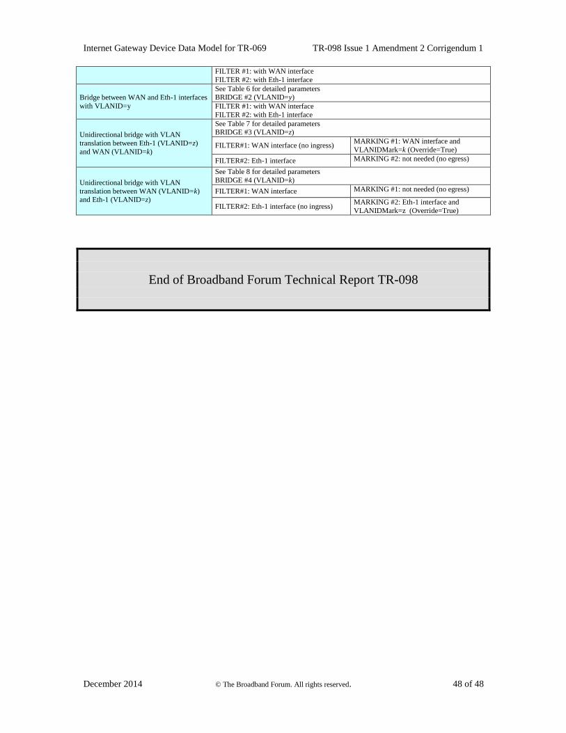
Internet Gateway Device Data Model for TR-069 TR-098 Issue 1 Amendment 2 Corrigendum 1
December 2014 © The Broadband Forum. All rights reserved. 48 of 48
FILTER #1: with WAN interface
FILTER #2: with Eth-1 interface
Bridge between WAN and Eth-1 interfaces
with VLANID=y
See Table 6 for detailed parameters BRIDGE #2 (VLANID=y)
FILTER #1: with WAN interface
FILTER #2: with Eth-1 interface
Unidirectional bridge with VLAN
translation between Eth-1 (VLANID=z)
and WAN (VLANID=k)
See Table 7 for detailed parameters BRIDGE #3 (VLANID=z)
FILTER#1: WAN interface (no ingress) MARKING #1: WAN interface and
VLANIDMark=k (Override=True)
FILTER#2: Eth-1 interface MARKING #2: not needed (no egress)
Unidirectional bridge with VLAN
translation between WAN (VLANID=k) and Eth-1 (VLANID=z)
See Table 8 for detailed parameters
BRIDGE #4 (VLANID=k)
FILTER#1: WAN interface MARKING #1: not needed (no egress)
FILTER#2: Eth-1 interface (no ingress) MARKING #2: Eth-1 interface and
VLANIDMark=z (Override=True)
End of Broadband Forum Technical Report TR-098