Embed Size (px)
Citation preview

Internship Report On
Power Generation, Transmission and Distribution of Ashuganj Power Station Company Limited
By
Tarik Reza (2008-1-80-007)
Khondokar Md. Ashiqur Rahman(2008-1-80-008)
Submitted to the
Department of Electrical and Electronic Engineering Faculty of Sciences and Engineering
East West University
in partial fulfillment of the requirements for the degree of Bachelor of Science in Electrical and Electronic Engineering
(B.Sc in EEE)
[Spring, 2012]
Approved By
Academic Advisor Academic Advisor Tahseen Kamal Dr. Khairul Alam
Department Chairperson Dr. Khairul Alam

Undergraduate Internship Report
Department of Electrical and Electronic Engineering, East West University 2
Approval Letter

Undergraduate Internship Report
Department of Electrical and Electronic Engineering, East West University 3
Approval Letter

Undergraduate Internship Report
Department of Electrical and Electronic Engineering, East West University 4
Acknowledgement Our heartfelt thanks go to Engr. Nurul Alam, Managing Director of Ashuganj Power Station
Company Limited (APSCL) for allowing us to do the Internship and to Mr. Lutfar Rahaman,
Manager, Training Division of APSCL for making arrangements and assigning us group wise to
Engineers who provides us the training with their immense knowledge.
We would also like to thank our advisor Tahseen Kamal, Senior Lecturer and Dr. Khairul Alam,
Associate Professor and chairperson, Department of Electrical and Electronic Engineering, East
West University Bangladesh.
We would also like to thank all our teachers, family and friends for giving us the support during
this period of Industrial Training. However, special thanks go to Engr. Md. Anwar Hossain,
(Manager- Operation), Engr. Bikas Ranjan Roy, (Manager- Instrumentation and Control), Engr.
Mostafizur Rahman, (Manager- Combined Cycle Power Plant), Engr. Noor Mohammad,
(Manager- Substation) and Senior Engr. Mohammad Kamruzzaman, (Generator and Protection
Division) for giving us their precious time for our training and for our acknowledgement of how
a Power Station of such magnitude works.
Not to mention that our thanks go to Almighty Allah for giving us the chance to fulfill our
Industrial Training smoothly.

Undergraduate Internship Report
Department of Electrical and Electronic Engineering, East West University 5
Executive Summary The objective of our internship was to get familiarized with the planning, generation and
distribution on the practical field of power sector. The objective was to gain firsthand knowledge
on the operations. During internship we got the opportunity to as a member of the engineering
team which was involved in Generation, Transformation, Transmission and the CCPP. We came
to know about the main principle to set up a power plant and that is Protection, Monitoring and
Vision. Among them protection is the most vital and crucial part of a power station. A power
station expends a huge part of their earnings behind the protection scheme. Ashuganj Power Station Company Limited (APSCL) holds the second largest power generation
in Bangladesh. With its 3 plants comprising of 8 units with an installed capacity of 724 MW
providing 15% power to the National Grid. However, it is not producing 724MW power due to
technical difficulties. The present de-rated capacity of the plant is 440 MW due to overhauling
phase of plant 1’s unit 1, plant 3s unit 3 and one GT of 54MW of the combined cycle power
plant.

Undergraduate Internship Report
Department of Electrical and Electronic Engineering, East West University 6
Training Schedule The following table shows the daily training schedule.
Day and Date
Starting time-Ending Time
Training Objectives
Instructors
Total Working Hour/Day
26/12/2011 to 28/12/2011
8.00 AM to 4.00 PM
Operational Procedure of Thermal Power Plants
Md. Anwar Hossain (Manager- Operation)
8 Hours
29/12/2011 to 01/01/2012
8.00 AM to 4.00 PM
Instrumentation and Control/Valve Control/Transducers
Bikas Ranjan Roy (Manager- Instrumentation & Control)
8 Hours
02/01/2012 To 04/01/2012
8.00 AM to 4.00 PM
Combined Cycle power Plant(Operation, maintenance and Control)
Md. Mizanur Rahman (Manager- CCPP)
8 Hours
05/01/2012 To 08/01/2012
8.00 AM to 4.00 PM
Sub-Station(Power Transformers- Maintenance and Operation)/ Incoming BUS line Controls
Noor Mohammad (Manager- Substation)
8 Hours
09/12/2012 To 11/01/2012
8.00 AM to 4.00 PM
Generator and Protection
Mohammad Kamruzzaman (Senior Engineer- Generator and Protection Division)
8 Hours

Undergraduate Internship Report
Department of Electrical and Electronic Engineering, East West University 7
Contents Approval Letter ....................................................................................................................................... 2
Approval Letter ....................................................................................................................................... 3
Acknowledgement ................................................................................................................................... 4
Executive Summary ................................................................................................................................ 5
Training Schedule ................................................................................................................................... 6
CHAPTER 1 ......................................................................................................................................... 12
1. Introduction ................................................................................................................................... 12
1.1 Company Overview ................................................................................................................... 12
1.2 Plant Orientation: ....................................................................................................................... 12
Figure 1.1 (a): Orientation of Thermal Power Station 64MW .............................................................. 12
Figure 1.1(b): Orientation of Combined Cycle Power Plants ............................................................... 13
Figure 1.1(c): Orientation of Thermal Power Station 150MW ............................................................. 13
Fig 1.1: The orientation of APSCL Power Plants .................................................................................. 13
1.3 Gas Scenario of APSCL ............................................................................................................. 13
1.4 Objective of Internship ............................................................................................................... 13
1.5 Scope and Methodology ............................................................................................................. 14
CHAPTER 2 ......................................................................................................................................... 15
2. Power Generation .......................................................................................................................... 15
2.1 Generators ................................................................................................................................. 15
Table 1: Information’s of APSCL’s generators and its ratings .......................................................... 16
2.1.1 AC Generators: ...................................................................................................................... 16
2.1.2 Working Principle of an AC Generator ................................................................................... 17
2.1.3 Excitation System of a Generator ........................................................................................... 17
Figure 2.1: Classification of Generator excitation ............................................................................... 18
2.1.3.1 AC excitation ......................................................................................................................... 18
Figure 2.2: Single Line diagram of an AC excitation system ................................................................. 18
2.1.3.2 Brushless Thyristor Excitation System ................................................................................... 19
2.1.4 Synchronization of generator .................................................................................................. 19
2.2 Steam Turbine Power Plant(Operation and Orientation) ............................................................. 20
2.2.2 Steam Turbine ........................................................................................................................ 20
2.2.3 Types of Steam turbine........................................................................................................... 20

Undergraduate Internship Report
Department of Electrical and Electronic Engineering, East West University 8
2.2.3.1 Impulse Turbine: .................................................................................................................... 21
2.2.3.2 Reaction Turbine : .................................................................................................................. 21
2.2.4 Steam Turbine orientation in APSCL ..................................................................................... 21
Figure 2.3: Arrangements of three turbine section ............................................................................. 22
2.2.4.1 High Pressure Turbine ............................................................................................................ 22
2.2.4.2 Intermediate Turbine .............................................................................................................. 22
2.2.4.3 Low Pressure Turbine ............................................................................................................ 22
2.3 Steam Generation....................................................................................................................... 22
2.3.1 Boiler ..................................................................................................................................... 23
2.3.1.1 Water tube boiler:................................................................................................................... 23
2.3.1.2 Fire Tube boiler ..................................................................................................................... 23
Figure 2.5: Fire tube boiler ................................................................................................................. 24
2.3.2 Burner .................................................................................................................................... 24
Figure 2.6: Burner arrangement for unit-5 ......................................................................................... 25
2.3.3 Boiler Drum ........................................................................................................................... 25
2.3.4 Super Heater (SH) .................................................................................................................. 25
2.3.5 Flue Gas ................................................................................................................................. 25
2.3.6 Re-heater (RH) ....................................................................................................................... 26
2.3.7 Condenser .............................................................................................................................. 26
Figure 2.7: Condenser of unit -4 ......................................................................................................... 26
2.3.7.1 Jet Condenser ......................................................................................................................... 27
2.3.7.2 Surface condenser .................................................................................................................. 27
2.3.8 Hotwell .................................................................................................................................. 28
2.3.9 Feed Water ............................................................................................................................. 28
2.3.10 Feed water Heater .................................................................................................................. 28
2.3.10.1 Low Pressure Heater (LP Heater) ....................................................................................... 29
Figure 2.8: LP heater of unit-3 ............................................................................................................ 29
2.3.10.2 High Pressure heater (HP Heater) ....................................................................................... 29
2.3.11 Feed water tank ...................................................................................................................... 29
Figure 2.9: Feed Water Tank unit-3 .................................................................................................... 30
2.3.12 Economizer ............................................................................................................................ 30
2.3.13 Deaerator ............................................................................................................................... 30

Undergraduate Internship Report
Department of Electrical and Electronic Engineering, East West University 9
2.3.13.1 Tray type ............................................................................................................................ 31
2.3.13.2 Spray type .......................................................................................................................... 31
2.3.14 Air pre-heater ......................................................................................................................... 31
2.3.15 Stack/Chimney ....................................................................................................................... 31
Figure 2.10: Stack/Chimney of unit-2 ................................................................................................. 32
2.3.16 Water treatment plant ............................................................................................................. 32
2.3.17 River water suction pump (RSP) ............................................................................................ 32
2.3.18 Condensate Extension Pump (CEP) ........................................................................................ 33
2.3.19 Boiler feed pump (BFP) ......................................................................................................... 33
2.3.20 Forced Draught fan (FD fan) .................................................................................................. 33
Figure 2.11: Force Draught Fan unit-3 ................................................................................................ 33
2.3.21 Forced draught fan actuator .................................................................................................... 33
Figure 2.12: Forced Draught fan actuator unit-3 ................................................................................ 34
2.3.22 Circulating water pump (CW pump) ....................................................................................... 34
2.3.22.1 Vertical types ..................................................................................................................... 34
2.3.22.2 Horizontal types ................................................................................................................. 34
CHAPTER 3 ......................................................................................................................................... 35
Combined Cycle Power Plant ................................................................................................................ 35
3. Combined Cycle Power Plant (CCPP): ........................................................................................... 35
Table 3.1: Information of combined cycle power plant of APSCL .................................................... 35
Figure 3.1: Top view of combined cycle power plant of APSCL ........................................................... 36
3.1 CCPP in APSCL: ....................................................................................................................... 36
3.2 Gas Turbine Section: .................................................................................................................. 36
3.2.1 Compressor: ........................................................................................................................... 36
Figure 3.2: Centrifugal compressor used in APSCL .............................................................................. 36
3.2.2 Combustion Chamber: ............................................................................................................ 37
Figure 3.3: Combustion Chamber of Gas Turbine Plant of APSCL ........................................................ 37
3.2.3 Gas Turbine: .......................................................................................................................... 37
Figure 3.4: Gas turbine of APSCL ........................................................................................................ 37
3.3 Diesel Engine: ........................................................................................................................... 38
Figure 3.5: Diesel engine use in the gas turbine ................................................................................. 38

Undergraduate Internship Report
Department of Electrical and Electronic Engineering, East West University 10
3.4 Steam Turbine Section: .............................................................................................................. 38
3.4.1 Steam Generation Process: ..................................................................................................... 39
Figure 3.6: Single line diagram of steam generation system of combined cycle power plant of APSCL 39
3.4.2 Different parts of steam turbine: ............................................................................................. 39
3.4.3 Condenser: ............................................................................................................................. 40
Figure 3.7: Condenser used in steam turbine section of combined cycle power plant (APSCL)............ 41
3.5 Valves used in Combined Cycle Power Plant: ............................................................................ 41
3.5.1 Isolation Valve: ...................................................................................................................... 41
3.5.2 Control Valve: ....................................................................................................................... 41
3.5.3 Manual Valve: ....................................................................................................................... 41
3.5.4 Pneumatic Valve: ................................................................................................................... 42
Figure 3.8: Pneumatic valve ............................................................................................................... 42
3.5.5 Hydraulic Valve: .................................................................................................................... 42
3.5.6 Motorized Valve: ................................................................................................................... 42
3.5.7 Electro-hydraulic Valve: ........................................................................................................ 42
3.5.8 Servo Valve: .......................................................................................................................... 43
Figure 3. 9: Servo valve ...................................................................................................................... 43
CHAPTER 4 ......................................................................................................................................... 44
4. Substation: ..................................................................................................................................... 44
Figure 4.5: Part of a Substation of APSCL ........................................................................................... 44
4.1 Different parts of a substation which we have seen in APSCL: ................................................... 44
4.1.1 Potential Transformer (PT): .................................................................................................... 44
Figure 4.6: Potential Transformer ...................................................................................................... 44
4.1.2 Current transformer (CT): ...................................................................................................... 45
Figure 4.3: Current Transformer ........................................................................................................ 45
4.1.3 Intermediate Potential transformer: ......................................................................................... 45
Figure 4.4: Intermediate Transformer ................................................................................................ 46
4.2 Protecting relays of substation: ................................................................................................... 46
Figure 4.5: Electronics relay. .............................................................................................................. 46
Figure 4.6: Electrical relay .................................................................................................................. 47
Figure 4.7: Fabricated Relay ............................................................................................................... 47
4.3 Bus bar: ..................................................................................................................................... 47

Undergraduate Internship Report
Department of Electrical and Electronic Engineering, East West University 11
4.4 Lightning arrester:...................................................................................................................... 48
4.5 Transmission Line: .................................................................................................................... 48
Figure 4.8: Transmission Line ............................................................................................................. 48
4.6 Isolator: ..................................................................................................................................... 48
Figure 4.9: Isolators ........................................................................................................................... 49
4.7 Circuit Breakers: ........................................................................................................................ 49
Figure 4.10: Oil Circuit Breaker .......................................................................................................... 50
Figure 4.11: SF6 Circuit Breaker ......................................................................................................... 50
Figure 4.12: Air blast circuit Breaker .................................................................................................. 51
4.8 Cable: ........................................................................................................................................ 51
Figure 4.13: Underground Cable for 132kv Line ................................................................................. 51
Figure 4.14: Coaxial Cable .................................................................................................................. 52
4.9 Tower: ....................................................................................................................................... 52
Figure 4.15: High Voltage Tower ........................................................................................................ 52
4.10 Feeder: ....................................................................................................................................... 52
4.11 AC and DC auxiliary system for Substation: .............................................................................. 53
Conclusion ......................................................................................................................................... 54
Appendix .............................................................................................................................................. 55

Undergraduate Internship Report
Department of Electrical and Electronic Engineering, East West University 12
CHAPTER 1
1. Introduction Ashuganj Power Station Company Limited is the second largest power station in Bangladesh
providing 15% of the total power to National Grid. The installed capacity by its 8 units is 746
MW. Due to recent technical difficulties and overhauling, the recent de-rated capacity is 440
MW.
1.1 Company Overview Company Name: Ashuganj Power Station Company Limited
Date of Incorporation: 28th June 2000.
Location: 90km west of Dhaka on the left bank of river Meghna.
Land: 311.22 Acres
Installed Capacity: 724 MW
No of Plants: 3
No of Units: 8
1.2 Plant Orientation:
Figure 1.1 (a): Orientation of Thermal Power Station 64MW
Plant 1Thermal Power
Plant
Unit 164MW
Unit 264MW

Undergraduate Internship Report
Department of Electrical and Electronic Engineering, East West University 13
Figure 1.1(b): Orientation of Combined Cycle Power Plants
Figure 1.1(c): Orientation of Thermal Power Station 150MW
Fig 1.1: The orientation of APSCL Power Plants
1.3 Gas Scenario of APSCL Strategically APSCL is situated in a good location of gas transmission and generation. All the
pipelines of the station is tied up with TITAS gas distribution and Gas Transmission Company
Limited (GTCL) installation. It has an gas allotment of 160 MSCFD (Million Standard Cubic
Feet per day).
1.4 Objective of Internship The main purpose of this internship is to complete the requirment of ou EEE undergraduate
programme. In this report we tried to give an overview of one of the most importatnt power
Plant 2
(2*56)MW Gas Turbine
(1*34)MW Steam Turbine with waste heat recovery unit
Combined Cycle power Plant
Plant 3Thermal power
Plant
Unit 3150 MW
Unit 4150MW
Unit 5150MW
Undergraduate Internship Report
Department of Electrical and Electronic Engineering, East West University 14
station of Bangladesh. We tried to cover its operation generation and protection schemes. The
main objectives are as follows
Understanding the company management.
Understanding the generation process.
Understanding the Protection system.
Understanding the Control system.
Understanding the troubleshooting incase of emergency.
Understanding the sunstation and incoming feeder lines.
1.5 Scope and Methodology This internship report based on the facts that we gathered during the training period where we
experienced and reviewed basic process of Ashuganj Power Station. This report also focuses on
organizational structures, background and objectives, generation process and generation strategy
of Ashuganj Power Station. Mainly this report emphasized on the generation process, protection
scheme, maintenance, control and evacuation techniques of Ashuganj Power Station Company
Limited.
This report has been produced with the aid of primary information that has been provided by
APSCL’s employee and secondary information procured from the company website.

Undergraduate Internship Report
Department of Electrical and Electronic Engineering, East West University 15
CHAPTER 2
2. Power Generation The conversion of energy available in different forms in nature into electrical energy is known as
generation of electrical energy. In Ashuganj power station, Steam Turbine Power Plant, Gas
Turbine Power Plant and Combined Cycle Power Plant is comissioned to generate electricity.
Centralized power generation became possible when it is discovered that AC power lines can
carry a large amount of power at long distance at a very low cost and by the techniques of
lowering or increasing the amount of power using Power transformer.
2.1 Generators Generators are electromechanical devices that converts mechanical energy into electrical energy
hence works as a power source for other machines. Electrical generators that we found in
APSCL are basically combustion engines, water turbines and. There are two types of generators
that can be found in Ashuganj Power Station power station:
a) AC Generator that generates alternating current which is also known as an alternator.
b) DC Generator which generates DC current.
In APSCL, both the above mentioned generators are used. Basically there are five generators in
steam turbine plants and three in combined cycle. All the generators are AC generators.
Undergraduate Internship Report
Department of Electrical and Electronic Engineering, East West University 16
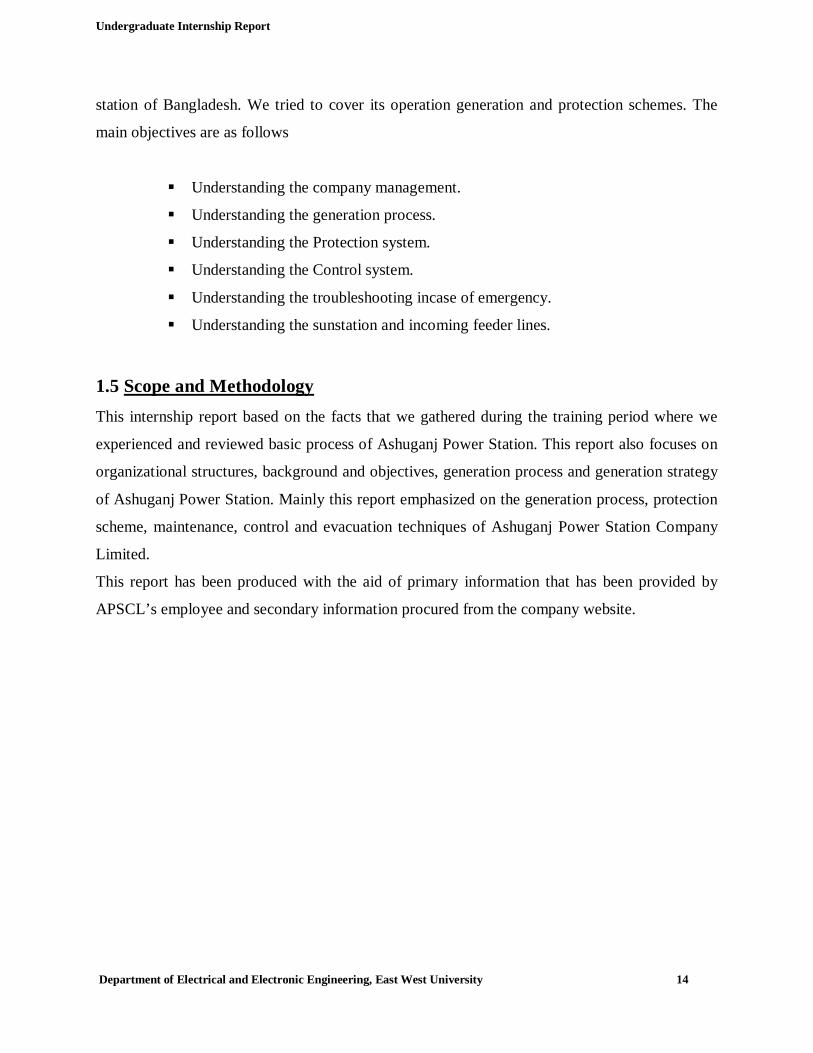
Table 1: Information’s of APSCL’s generators and its ratings
The below mentioned table shows the detailed information of APSCLS’s generators
Category Steam power plant section
Combined cycle power plant section
Unit 1,2 Unit 3,4,5 Gas turbine 1 & 2
Steam turbine
Name of the maker company
BBC,Germany ABB,Germany GEC,UK GEC,UK
Rated terminal output 64 MW 150 MW 55.67 MW 34.33 MW
Rated terminal voltage 11 KV 15.75 KV 38.8 KV 13.8 KV
Rated power factor 0.8 0.8 0.8 0.8
Rated current 4200/4690 A 6965 A 2911 A 1799 A
Rated frequency 50 Hz 50 Hz 50 Hz 50 Hz
Number of poles 2 2 2 2
2.1.1 AC Generators: AC generators are electromechanical devices that convert mechanical energy into alternating
current. In APSCL, the generators are constructed consisting the below mentioned parts.
a) Field: Consists coils of conductors that receive voltage from a source called exciter and
produce magnetic flux. This fluxes cut the armature in order to produce voltage. This voltage
is the terminal output of the generator.
b) Armature: This is the part where the voltage is produced. Armature consist many coils that
are large enough to carry out full-load current of a generator.
c) Rotor: The rotating component of an AC generator is known as the rotor which is driven by
the prime mover (steam engine, gas engine). Depending on the type of generator this can be
the armature or the field. If the output voltage is induced here then it is the armature. If
external source is applied here then it works as a field. In APSCL, the rotor is used as field
exciter.

Undergraduate Internship Report
Department of Electrical and Electronic Engineering, East West University 17
d) Stator: Stator is the part which is stationery. It also follows the same principle of being an
armature or field. In APSCL, stator is used as armature.
e) Slip Rings: Slip rings are tube like rings which is circular in shape, connected to the
armature and rotate with it. It is usually made of nonferrous materials like bronze or copper.
f) Brushes: Brushes are connected to slip rings and resistive load. Their job is to conduct
electricity to load from the slip rings.
g) Armature Windings: These are first windings in form of flat rectangular coils which are
pulled into their proper shape by a coil puller. The coils are insulated from each other. The
coils are placed in such a way in form a line that is insulated with tough material.
h) Field Poles: The pole cores are made of solid steel castings. At the air gap poles usually fan
out into what is known as pole head. This is done to reduce the reluctance of the air gap. The
field coils are placed on the poles and then the whole assembly is mounted on yoke.
i) Yoke: It’s a circular steel ring that supports the field poles mechanically and provides
magnetic path between the poles. The yoke can be laminated or solid.
2.1.2 Working Principle of an AC Generator The operation of electric generators is based on the phenomenon of electromagnetic induction.
Whenever a conductor moves relative to a magnetic field, voltage is induced in the conductor. If
a magnet is spinning inside a coil, AC voltage is induced in the coil. The induced voltage which
is known as electromagnetic force or EMF will create current through an external circuit
connected to the coil, resulting in energy being delivered to the load. Thus the kinetic energy that
spins the source of the magnetic field is converted into electricity. The current flowing through
an external load in turn creates a magnetic field that oppose the change in the flux of the coil, so
the coil opposes the motion, The higher the current, the larger the force that must be applied to
the magnet to keep it from slowing down.
2.1.3 Excitation System of a Generator
Exciter or Excitation is the father of generator control system. It is the source of power that
induces DC magnetizing current to the field windings of a synchronous generator. As a result the
magnetizing current induces AC voltage and current in the generator armature.

Undergraduate Internship Report
Department of Electrical and Electronic Engineering, East West University 18
There are four types of excitation system in a generator:
Figure 2.1: Classification of Generator excitation
2.1.3.1 AC excitation AC excitation system is used widely. In APSCL unit1 and unit2 uses AC excitation system. This
system consists of a sub- pilot exciter of a permanent magnet type, pilot exciter and the main AC
exciter which is all coupled to the main generator along the same shaft. The permanent magnet
type generator is a single phase generator where the field is produced by permanent magnet. The
single phase supply from the armature is converted to dc by using a rectifier and the dc supplies
the field of the pilot and main exciter. The pilot exciter and the main exciter are three phase
machines. The potential transformer supplies the voltage proportional to generator voltage to
magnetic amplifier.
Figure 2.2: Single Line diagram of an AC excitation system
Excitation System of generator
AC excitation
DC excitation
Brushless thyristor
excitation
Static excitation

Undergraduate Internship Report
Department of Electrical and Electronic Engineering, East West University 19
2.1.3.2 Brushless Thyristor Excitation System This system is used to excite gas turbine generators in APSCL.
A brushless diode excitation system consists of an exciter having stationary field system and a
rotating armature diode rectifier assembled in such a way that is coupled solidly to the main
generator rotor. In this system the most commonly used rectifier configuration is the three phase
bridge. If silicon diodes are replaced by thyristors and suitable arrangements are made to apply
firing pulses to their gates with firing angle under control then it is possible to change the
excitation voltage over the range of 10 milliseconds or less. The input voltage of thyristor
converter has a constant value equivalent to the excitation voltage required by the generator. The
thyristor converter performs dual function. The functions are rectification and control of the
voltage supplied to the generator field.
2.1.4 Synchronization of generator Synchronizing a generator on the grid is one of the most important tasks in power generation.
Synched generator means the generator is working equally with the nationwide generators.
Synchronization is basically the process of connecting a three phases synchronous or AC
generator to another generator or to a power grid. However, to synchronize a generator four
conditions must be met beforehand.
Frequency
The generator must be driven by the prime mover at such a speed that the generated power
frequency is equal to the grid’s frequency.
Voltage
The stator line voltage or the output voltage of a generator must be equal to grid’s voltage. The
stator line voltage is maintained by controlling the rotor current.
Phase sequence
Phase sequence of the generator must be equal to the phase sequence of the grid. If the grid
sequence is R-Y-B then the generator sequence must be also R-Y-B.

Undergraduate Internship Report
Department of Electrical and Electronic Engineering, East West University 20
Phase Angle
The phase angle of a generator and the phase angle of a grid must be equal. By adjusting the field
current the stator angle can be controlled.
2.2 Steam Turbine Power Plant(Operation and Orientation)
2.2.1 Steam Turbine
Turbine is a device that spins in the presence of a moving fluid. In this device, kinetic energy of
a dynamic fluid is converted into mechanical power by the impulse or reaction of a fluid with a
series of buckets, paddles, blades arrayed about the circumference of a wheel or cylinder.
There are nine types of turbine that are used worldwide.
Steam Turbine
Gas Turbine
Water turbine
Wind Turbine
Transonic Turbine
Ceramic Turbine
Stator less turbine
Blade less Turbine
Soundless Turbine
Ashuganj Power Station uses steam and gas turbine for power generation.
2.2.2 Steam Turbine Steam turbine converts heat energy fed from coal or natural gas into mechanical energy thus
producing electricity. In APSCL, there are three steam turbine power plants.
2.2.3 Types of Steam turbine In APSCL, according to their working principle, steam turbine can be classified into two types
Undergraduate Internship Report
Department of Electrical and Electronic Engineering, East West University 21
a) Impulse Turbine
b) Reaction Turbine
2.2.3.1 Impulse Turbine: In this system the whole pressure of water is converted into kinetic energy in a nozzle and the
velocity of the jets drive the wheel. It consists a wheel fitted with elliptical buckets along its
periphery. The force of water jet striking the buckets on the wheel drives the turbine. The
quantity of water jet falling on the turbine is controlled by means of needle or spear placed at the
top of the nozzle. The movement of the needle is controlled by a governor. If the load on turbine
decreases the governor pushes the needle into the nozzle, reducing the quantity of water striking
the bucket.
Unit 1-5 of APSCL uses turbines of impulse type.
2.2.3.2 Reaction Turbine : It consists of an outer ring of stationery guide blades fixed to the turbine casing and an inner ring
of rotating blades forming the runner. The guide blades control the flow of water to the turbine.
Water flows radially inwards and changes to a downward direction while passing through the
runner. As the water passes over the rotating blades of t he runner, both pressure and velocity of
water are reduced. This causes a reaction force that drives the turbine.
2.2.4 Steam Turbine orientation in APSCL The steam turbines used in APSCL can be divided into three parts or chambers. The size and
characteristics of these turbines are different from each other. The three parts of steam turbines
are
a) High pressure turbine(HP turbine)
b) Intermediate turbine(IP turbine)
c) Low pressure turbine(LP turbine)

Undergraduate Internship Report
Department of Electrical and Electronic Engineering, East West University 22
Figure 2.3: Arrangements of three turbine section
2.2.4.1 High Pressure Turbine The high speed steam incoming from super heater enter the high pressure turbine chamber first.
The blades of this turbine are smallest of all turbine blades. This is because to balance the thrust
of the incoming high energy of steam which has also low volume. The blades are fixed to a shaft
and the steam hits the blades causes the rotation of the shaft.
2.2.4.2 Intermediate Turbine The steam enters the intermediate pressure turbine from boiler re-heater. The volume of steam
expands and losses energy when entering this part. Therefore the turbine blades are bigger than
HP turbine. From this part the steam goes to the low pressure turbine.
2.2.4.3 Low Pressure Turbine From IP turbine steam enters here and continues to expand. The blades of this turbine are much
larger than the previous two but the energy of steam is much lesser.
2.3 Steam Generation The main ingredient to generate steam is water and this water has to pass through a series of
mechanical systems to achieve the desired steam that rotates the turbines thus generating power.
The processes are as follows:

Undergraduate Internship Report
Department of Electrical and Electronic Engineering, East West University 23
2.3.1 Boiler The equipment used for producing steam is called boiler.
There are two types of boiler that are in use at APSCL. They are
a) Water tube boiler
b) Fire tube boiler
2.3.1.1 Water tube boiler: In this type, the water tubes are arranged inside a furnace in a number of possible configurations
often the water tubes connect large drums, the lower ones containing water and the upper ones,
steam and water; in other cases, such as a mono tube boiler, water is circulated by a pump.
Figure 2.4: Water tube boiler
This type generally gives high steam production rates, but less storage capacity than the above.
Water tube boilers can be designed to exploit any heat source and are generally preferred in high
pressure applications since the high pressure water/steam is contained within small diameter
pipes which can withstand the pressure with a thinner wall.
2.3.1.2 Fire Tube boiler Water partially fills a boiler barrel with a small volume left above to accommodate the steam
(steam space). This is the type of boiler used in nearly all steam locomotives. The heat source is
inside a furnace or firebox that has to be kept permanently surrounded by the water in order to
maintain the temperature of the heating surface just below boiling point.

Undergraduate Internship Report
Department of Electrical and Electronic Engineering, East West University 24
Figure 2.5: Fire tube boiler The furnace can be situated at one end of a fire-tube which lengthens the path of the hot gases,
thus augmenting the heating surface which can be further increased by making the gases reverse
direction through a second parallel tube or a bundle of multiple tubes (two-pass or return flue
boiler); alternatively the gases may be taken along the sides and then beneath the boiler through
flues (3-pass boiler). In the case of a locomotive-type boiler, a boiler barrel extends from the
firebox and the hot gases pass through a bundle of fire tubes inside the barrel which greatly
increase the heating surface compared to a single tube and further improve heat transfer. Fire-
tube boilers usually have a comparatively low rate of steam production, but high steam storage
capacity. Fire-tube boilers mostly burn solid fuels, but are readily adaptable to those of the liquid
or gas variety.
2.3.2 Burner Burner also known as furnace is the chamber where the water is transformed into steam. Here
natural gas or coal is burner with the presence of air for producing heated gas or flue gas.
APSCL use natural gas for generating steam. In APSCL each furnace chamber has nine burners
in total.

Undergraduate Internship Report
Department of Electrical and Electronic Engineering, East West University 25
Figure 2.6: Burner arrangement for unit-5 The temperature inside the burner is 1200-1500℃. The water after being treated passes the
economizer enters the furnace through tubes and the flue gas produced inside the furnace passes
through the tubes. Flue gas releases heat to the water and the water becomes saturated steam
whose temperature is 260℃.
2.3.3 Boiler Drum This is the reserved drum where the steam coming from furnaces are reserved. The steam
pressure is controlled by maintaining the upper and lower level of steam. Any anomalies like
going off the limits (upper and lower) will trip the plant. Its is very important to control the
saturated steam level. From the boiler drum the saturated steam is transferred to super heater.
2.3.4 Super Heater (SH) In this part, saturated steam is converted into super heated steam. It is a part insode the burner. In
super heated steam there will be no water particles. In fact it transforms the saturated steam into
dry saturated steam. The temperature of the super heated steam is approximately 523℃ and it is
supplied to the HP turbine with a pressure of 132 Bar.
2.3.5 Flue Gas It is the heated gas which was produced inside the furnace with the mixture of natural gas and
air. The operating principle of this flue gas is to release heat to the water in order to generate
steam and after that it is released into air through stack or chimney.

Undergraduate Internship Report
Department of Electrical and Electronic Engineering, East West University 26
2.3.6 Re-heater (RH) Re-heater is a part where the steam is re-heated that comes from the high pressure turbine. At
this stage the steam is known as exhaust gas.
APSCL has two re-heaters inside the boiler in which RH2 produces steam of about 522℃ and
29.4 Bar of pressure. From re-heater the exhaust gas goes inside the intermediate turbine.
The difference between a super heater and re-heater is super heater can increase the temperature
and pressure of steam but a re-heater can only reheat the steam.
2.3.7 Condenser Condenser is a device that condenses the steam coming from the turbine exhaust for re using.
Condenser serves two important functions. It creates a very low pressure at the exhaust of the
turbine causing the expansion of the steam in the prime mover at a very low pressure. The steam
then transforms its heat energy to
Figure 2.7: Condenser of unit -4 mechanical energy in the prime mover. It also can be used as feed water to the boiler. According
to their working principle boilers can be divided into two types:
a) Jet condenser
b) Surface condenser

Undergraduate Internship Report
Department of Electrical and Electronic Engineering, East West University 27
2.3.7.1 Jet Condenser In this condenser cooling water and steam are mixed together.
Advantages:
a) Low cost
b) Less floor area required
c) Less cooling water required
d) Low maintenance charge
Disadvantages:
a) Condensate is wasted
b) High power required for pumping
2.3.7.2 Surface condenser APSCL uses surface condenser in Unit 1-5.
A surface condenser is a commonly used term for a water-cooled shell and tube heat
exchanger installed on the exhaust steam from a steam turbine in thermal power stations. In this
condenser there is no direct contact between cooling water and exhaust steam. The cooling water
flows through the tubes and the exhaust steam over the surface of the tubes. The steam transfers
the heat to the water and condensate.
The purpose of using the surface condenser is because the steam turbine itself is a device to
convert the heat in steam to mechanical power. The difference between the heat of steam per unit
mass at the inlet to the turbine and the heat of steam per unit mass at the outlet to the turbine
represents the heat which is converted to mechanical power. Therefore, the more the conversion
of heat per pound or kilogram of steam to mechanical power in the turbine, the better is its
efficiency. By condensing the exhaust steam of a turbine at a pressure below atmospheric
pressure, the steam pressure drop between the inlet and exhaust of the turbine is increased, which
increases the amount of heat available for conversion to mechanical power. Most of the heat
liberated due to condensation of the exhaust steam is carried away by the cooling medium (water
or air) used by the surface condenser.
Undergraduate Internship Report
Department of Electrical and Electronic Engineering, East West University 28
Advantages:
a) Condensed can be used as feed water.
b) Less power for pumping is required.
Disadvantages
a) High initial cost.
b) Requires large floor area.
c) High maintenance cost.
2.3.8 Hotwell After the steam turned into water in surface condenser, it is kept in reserve into hot-well. From
the hot-well the water is supplied to low pressure heater (LP heater) by condensate extension
pump (CEP). Make up water from the water treatment plant is supplied to hot-well if the water
level decreases.
2.3.9 Feed Water Feed water is the water that comes from condenser. In other words feed water is the condensate
water that feeds the boiler. The feed water is heated by heaters and economizer while going into
the boiler and helps the overall efficiency of the plant. During the process some water might be
lost so it has to make up the lost water that comes from water treatment plant. This water is
called make-up water.
2.3.10 Feed water Heater It is a water heater that pre- heats water before going into the boiler. Pre-heating reduces the
irreversibility involved in steam generation thus improving the thermodynamic efficiency of the
system. This feed water comes from HP, LP turbine through steam extraction line.
There are two types of water heater in APSCL.
a) Low pressure heater(LP heater)
b) High pressure heater(HP heater)
Undergraduate Internship Report
Department of Electrical and Electronic Engineering, East West University 29
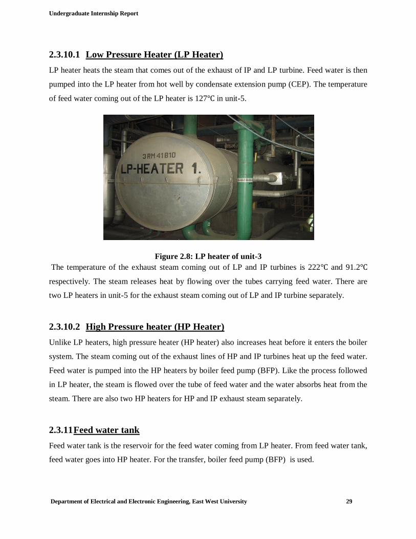
2.3.10.1 Low Pressure Heater (LP Heater) LP heater heats the steam that comes out of the exhaust of IP and LP turbine. Feed water is then
pumped into the LP heater from hot well by condensate extension pump (CEP). The temperature
of feed water coming out of the LP heater is 127℃ in unit-5.
Figure 2.8: LP heater of unit-3 The temperature of the exhaust steam coming out of LP and IP turbines is 222℃ and 91.2℃
respectively. The steam releases heat by flowing over the tubes carrying feed water. There are
two LP heaters in unit-5 for the exhaust steam coming out of LP and IP turbine separately.
2.3.10.2 High Pressure heater (HP Heater) Unlike LP heaters, high pressure heater (HP heater) also increases heat before it enters the boiler
system. The steam coming out of the exhaust lines of HP and IP turbines heat up the feed water.
Feed water is pumped into the HP heaters by boiler feed pump (BFP). Like the process followed
in LP heater, the steam is flowed over the tube of feed water and the water absorbs heat from the
steam. There are also two HP heaters for HP and IP exhaust steam separately.
2.3.11 Feed water tank Feed water tank is the reservoir for the feed water coming from LP heater. From feed water tank,
feed water goes into HP heater. For the transfer, boiler feed pump (BFP) is used.

Undergraduate Internship Report
Department of Electrical and Electronic Engineering, East West University 30
Figure 2.9: Feed Water Tank unit-3
2.3.12 Economizer Economizer is a mechanical device intended to reduce energy consumption, or to perform
another useful function such as preheating a fluid. The term economizer is used for other
purposes as well. Boiler, power plant, and heating, ventilating, and air-conditioning (HVAC)
uses are discussed in this article. In simple terms, an economizer is a heat exchanger. It also
helps to recover the heat carrying out by flue gases. This recovered heat is used in increasing
temperature of feed water.
2.3.13 Deaerator A Deaerator is a device that is widely used for the removal of oxygen and other
dissolved gases from the feed water to steam-generating boilers.
In particular, dissolved oxygen in boiler feed waters will cause serious corrosion damage in
steam systems by attaching to the walls of metal piping and other metallic equipment and
forming oxides (rust). Water also combines with any dissolved carbon dioxide to form
carbonic that causes further corrosion. Most Deaerator are designed to remove oxygen down to
levels of 7 ppb by weight (0.005 cm³/L) or less.
There are two types of Deaerator used in steam power stations. They are:

Undergraduate Internship Report
Department of Electrical and Electronic Engineering, East West University 31
2.3.13.1 Tray type Tray type which is also known as cascade type deaerator includes a vertical domed deaeration
section mounted on top of a horizontal cylindrical vessel which serves as the deaerated boiler
feed water storage tank.
2.3.13.2 Spray type The spray-type consists only of a horizontal (or vertical) cylindrical vessel which serves as both
the deaeration section and the boiler feed water storage tank.
In APSCL, spray type Deaerator is used.
2.3.14 Air pre-heater An air pre-heater (APH) is a general term to describe any device designed to heat air before
another process (for example, combustion in a boiler) with the primary objective of increasing
the thermal efficiency of the process. They may be used alone or to replace a recuperative heat
system or to replace a steam coil.
The purpose of the air pre-heater is to recover the heat from the boiler flue gas which increases
the thermal efficiency of the boiler by reducing the useful heat lost in the flue gas. As a
consequence, the flue gases are also sent to the flue gas stack (or chimney) at a lower
temperature, allowing simplified design of the ducting and the flue gas stack. It also allows
control over the temperature of gases leaving the stack.
2.3.15 Stack/Chimney A flue-gas stack is a type of chimney, a vertical pipe, channel or similar structure through which
combustion product gases called flue gases are exhausted to the outside air. Flue gases are
produced when coal, oil, natural gas, wood or any other fuel is combusted in an industrial
furnace, a plant’s steam-generating boiler, or other large combustion device.

Undergraduate Internship Report
Department of Electrical and Electronic Engineering, East West University 32
Figure 2.10: Stack/Chimney of unit-2 Flue gas is usually composed of carbon dioxide (CO2) and water vapor as well as nitrogen and
excess oxygen remaining from the intake combustion air. It also contains a small percentage of
pollutants such as particulate matter, carbon monoxide, nitrogen oxides and sulfur oxides. The
flue gas stacks are often quite tall, up to 400 meters (1300 feet) or more, so as to disperse the
exhaust pollutants over a greater area and thereby reduce the concentration of the pollutants.
2.3.16 Water treatment plant The source of water required for steam generation usually comes from river containing dissolved
gas and other particles that could be harmful for boiler and other components. Boiler requires
clean and soft water for longevity and better efficiency. Therefore, the water is needed to be
purified before in taking for the steam generation. Water treatment plant of a power station does
the above work. The process includes sedimentation, coagulation and filtration to remove the
impurities. Dissolved gases are removed by aeration. At last, the pure and soft water is fed to the
boiler.
The water is supplied using the following pumps in APSCL.
2.3.17 River water suction pump (RSP) The pumps are used for sucking river water into the reservoir for circulation into the power
station after going through treatment procedure. Majority of the pumps used for circulation or
transferring uses 6.6KV voltage.

Undergraduate Internship Report
Department of Electrical and Electronic Engineering, East West University 33
2.3.18 Condensate Extension Pump (CEP) This pump is used to transfer condensate water of hot-well to the low pressure heater. There are
two condensate pumps used in APSCL for each boiler. One is operational and one is standby.
2.3.19 Boiler feed pump (BFP) Boiler feed pump is used for transferring feed water to HP heater from feed water tank. It pumps
feed water to high pressure heater and then through economizer. Unlike CEP, there are two BFP
where one is operational and the other is standby.
2.3.20 Forced Draught fan (FD fan) This is the main air intake fan that feeds air into the boiler from the nature and acts as a boiler
combustion air source. Each unit has two FD fan both working simultaneously.
Figure 2.11: Force Draught Fan unit-3 The amount of air intakes inside the boiler depends on the air pressure inside. Forced draught fan
actuator is used to control the air pressure inside the boiler.
2.3.21 Forced draught fan actuator FD fan actuator is basically a three phase dc motor with a lever attached to a damper inside the
fan.

Undergraduate Internship Report
Department of Electrical and Electronic Engineering, East West University 34
Figure 2.12: Forced Draught fan actuator unit-3
When the air pressure inside the boiler drops, the actuator moves clockwise and opens the
damper for the fan to suck in more air and decreases the intake air by moving counter-clockwise.
2.3.22 Circulating water pump (CW pump) CW pump usually used to circulate cooling water to the condenser. Depending on the source of
water there are two types.
2.3.22.1 Vertical types Usually used while in- taking water direct from sea or river. In APSCL, vertical CW pump is
used as it takes in water from the river Meghna.
2.3.22.2 Horizontal types Horizontal type is used while taking water from the cooling tower. This type of CW pumps has
controllable movable impeller or lever which is called variable pitch vane type.

Undergraduate Internship Report
Department of Electrical and Electronic Engineering, East West University 35
CHAPTER 3
Combined Cycle Power Plant
3. Combined Cycle Power Plant (CCPP): As per our schedule we were assigned to visit CCPP (Combined Cycle Power Plant) unit from
2nd to 4th January. When we visited Combined Cycle Power Plant, at first our instructor gave us a
little discussion about it. It is a different type of power generation plant from all others in
Ashuganj Power Station. It produces power from gas turbine initially and then produces more
power from exhausted gas again. The secondary generator is a steam generator. It takes energy
from the heat of exhausted gas which has a temperature of about 450-650 C̊. It was made to
make a power generator more efficient. Normal gas turbine fuel efficiency is usually 50%. The
remaining heat from combustion is generally wasted. Combining two or more thermodynamic
cycle’s results in an improved overall efficiency and reduction in fuel costs.
Combined cycle power plant consists of two sections. These are:
a) Gas turbine section.
b) Steam turbine section.
Table 3.1: Information of combined cycle power plant of APSCL
Category Combined cycle power plant section
Gas turbine 1 & 2 Steam turbine
Name of the maker company GEC,UK GEC,UK
Rated terminal output 55.67 MW 34.33 MW
Live steam pressure(Pabs) Flue gas 39 bar
Live steam temperature 1010°C 490°C
Number of stages - 17
Rated speed 3000rpm 3000rpm
Direction of rotation Clockwise Clockwise

Undergraduate Internship Report
Department of Electrical and Electronic Engineering, East West University 36
Figure 3.1: Top view of combined cycle power plant of APSCL
3.1 CCPP in APSCL: In APSCL there are two gas turbine generators for CCPP named gas station 1&2. Though both
are coupled with steam turbine, only one is used for combined cycle at a time now. Each
generates approximately 45 MW and the coupled steam turbine generates almost 23 MW.
3.2 Gas Turbine Section: Then we have visited the gas turbine section, learn about different parts of it and saw how they
work. Some of them are discussed below:
3.2.1 Compressor: Compressor is a device in the gas turbine section which is used to compress the air which is
needed to expand by the help of combustion of fuel to create mechanical energy to rotate the
turbine. In gas turbine section of APSCL centrifugal compressor is used.
Figure 3.2: Centrifugal compressor used in APSCL

Undergraduate Internship Report
Department of Electrical and Electronic Engineering, East West University 37
3.2.2 Combustion Chamber: The combustion chamber consists of a vessel into which pressurized air and pressurized fuel (oil,
natural gas) are fed in appropriate proportions, finally mixed, ignited and fed into the turbine at
correct turbine entry temperature. The pressure in the combustion chamber is decided by the
outlet pressure of the compressor, which feeds air directly to the chamber. About 30% of the
main flow of air passes into the burner area as primary air. The air fuel ratio in the area is
maintained at about 15:1.
Figure 3.3: Combustion Chamber of Gas Turbine Plant of APSCL
3.2.3 Gas Turbine: It is the most important part of the gas turbine section. The products of combustion consisting of
a mixture of gases at high temperature and pressure are passed to the gas turbine. These gases in
passing over the turbine blades expand and thus do the mechanical work. In gas turbine section
of APSCL shaft type gas turbine is used.
Figure 3.4: Gas turbine of APSCL

Undergraduate Internship Report
Department of Electrical and Electronic Engineering, East West University 38
3.3 Diesel Engine: It is a very essential part in gas turbine power plant. The gas turbine is not a self exciting
machine. The turbine only can be rotated if fuel and air is burned inside the combustion chamber.
But before the turbine starts the air cannot be sucked by the compressor automatically because
the compressor is coupled with the turbine.
So a diesel engine is coupled with the turbine to rotate the turbine at the beginning for helping to
suck air by the compressor. At first the diesel engine starts. When the turbine starts to move by
the diesel engine at a rated speed which makes the compressor to suck air by itself then the diesel
engine is turned off.
Figure 3.5: Diesel engine use in the gas turbine
3.4 Steam Turbine Section: After that we have visited the Steam turbine section. In combined cycle power plant the exhaust
gas which comes out from the gas turbine is used to produce steam and run a steam turbine. The
exhaust gas has very high temperature which can be used to create steam by using several
equipments.
The main difference between the steam turbine section of combined cycle power plant to the
steam turbine section of steam power plant is in the steam power plant there is a furnace which
produce the heat or flue gas but in the combined cycle there is no furnace, steam is produced by
the heat of exhaust gas.
In combined cycle power plant of APSCL there is one steam turbine section which runs by the
exhaust gas of gas turbine-1 & 2.
Undergraduate Internship Report
Department of Electrical and Electronic Engineering, East West University 39
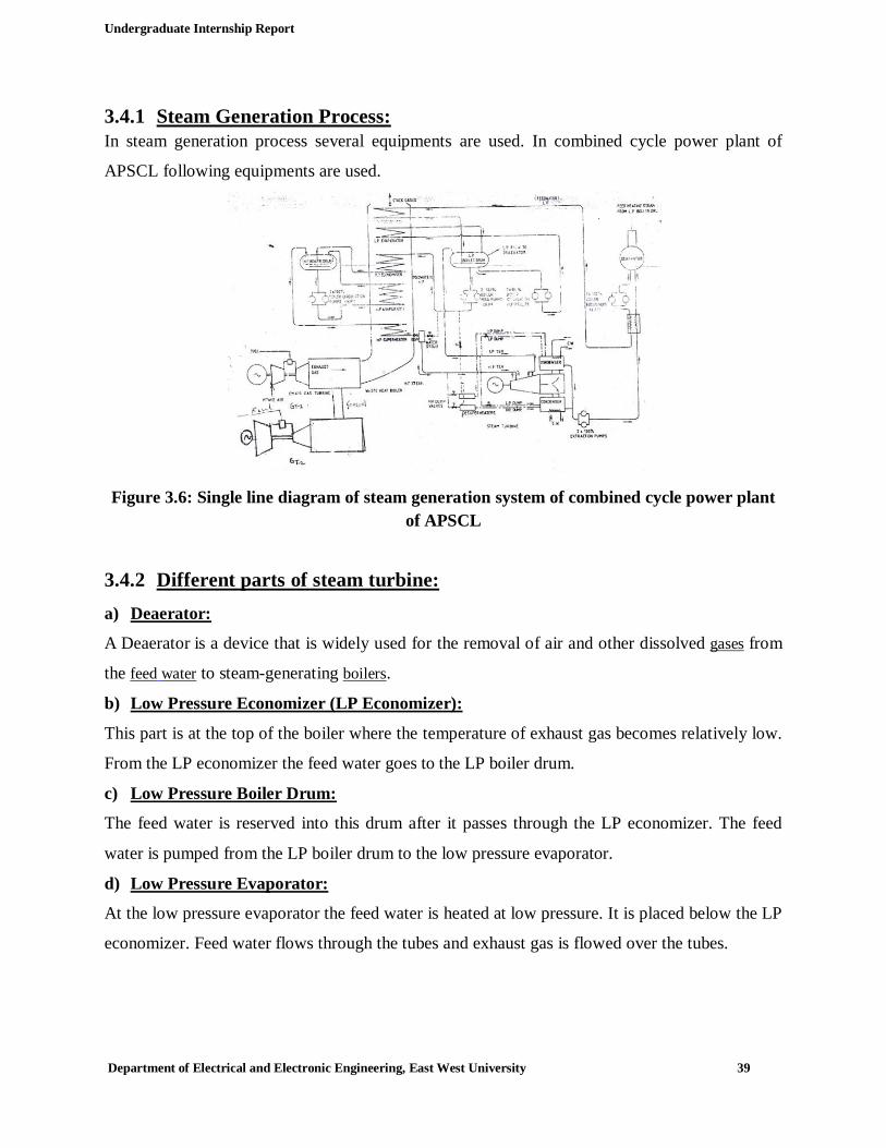
3.4.1 Steam Generation Process: In steam generation process several equipments are used. In combined cycle power plant of
APSCL following equipments are used.
Figure 3.6: Single line diagram of steam generation system of combined cycle power plant of APSCL
3.4.2 Different parts of steam turbine: a) Deaerator:
A Deaerator is a device that is widely used for the removal of air and other dissolved gases from
the feed water to steam-generating boilers.
b) Low Pressure Economizer (LP Economizer):
This part is at the top of the boiler where the temperature of exhaust gas becomes relatively low.
From the LP economizer the feed water goes to the LP boiler drum.
c) Low Pressure Boiler Drum:
The feed water is reserved into this drum after it passes through the LP economizer. The feed
water is pumped from the LP boiler drum to the low pressure evaporator.
d) Low Pressure Evaporator:
At the low pressure evaporator the feed water is heated at low pressure. It is placed below the LP
economizer. Feed water flows through the tubes and exhaust gas is flowed over the tubes.

Undergraduate Internship Report
Department of Electrical and Electronic Engineering, East West University 40
e) High Pressure Economizer (HP Economizer):
At high pressure economizer the temperature of feed water raises higher. Then the feed water is
supplied to the high pressure boiler drum. Boiler feed pump is used to flow the water from LP
boiler drum to HP boiler drum. When feed water passes through the HP economizer the
temperature raises up to 220°C.
f) High Pressure Boiler Drum:
The feed water is reserved into this drum after it passes through the HP economizer. The feed
water is pumped from the HP boiler drum to the high pressure evaporator.
g) High Pressure Evaporator:
From the HP boiler drum feed water is transferred to the high pressure evaporator where the feed
water becomes saturated steam by the help of the heat of exhaust gas. From the HP boiler drum
the steam is then flowed to the super heater.
h) Super Heater:
This part is at the bottom of the boiler where the temperature of the exhaust gas is highest. At
this part the saturated steam becomes super heated steam. Exhaust gas is flowed over the bundle
of tubes which carry the steam. At the super heater the temperature of the exhaust gas that comes
from the gas turbine is about 500°C. From the super heater the super heated steam goes to the
high pressure turbine at a temperature of 400°C and pressure of 40 bar.
3.4.3 Condenser: A condenser is a device which condenses the steam at the exhaust of turbine. It serves two
important functions. Firstly, it creates a very low pressure at the exhaust of turbine, thus
permitting expansion of the steam in the prime mover to a very low pressure.

Undergraduate Internship Report
Department of Electrical and Electronic Engineering, East West University 41
This helps in
Figure 3.7: Condenser used in steam turbine section of combined cycle power plant (APSCL)
converting heat energy of steam into mechanical energy in the prime mover. Secondly, the
condensed steam can be used as feed water to the boiler.
In combined cycle power plant of APSCL there are two condensers.
3.5 Valves used in Combined Cycle Power Plant: Valves are of two kinds. These are:
3.5.1 Isolation Valve: It is an on/off valve that typically operates in two positions; the fully open and fully closed
position.
3.5.2 Control Valve: It can be controlled. This valve can regulate the fluid flow in a piping system.
In combined cycle power plant there are various types of vales. These are:
3.5.3 Manual Valve: Manual valves are those valves that operate through a manual operator (such as a hand wheel or
hand lever), which are primarily used to stop and start flow (block or on–off valves), although
some designs can be used for basic throttling.It is an isolation valve. Only on/off operation is
possible by this.

Undergraduate Internship Report
Department of Electrical and Electronic Engineering, East West University 42
3.5.4 Pneumatic Valve: It is a valve in which the force of compressed air against a diaphragm is opposed by the force of
a spring to control the area of the opening for a fluid stream.
Figure 3.8: Pneumatic valve In APSCL control room sends electrical signals of 4-20 mA to field where I/P converter convert
these electrical signals into pneumatic signals. Actuators use these signals to operate the valve.
Actuators move the and down depending upon input signals and control the valve opening.
3.5.5 Hydraulic Valve: It is a valve which is used for regulating the distribution of water in the cylinders of hydraulic
elevators, cranes, etc.
3.5.6 Motorized Valve: Valves which are controlled by motor are called motorized valve. By running the motor
clockwise and anti clockwise a motorized valve can be opened or closed. It is a control valve.
The speed of the motor controls how fast or slow the valve is opening and closing. If it is an
emergency opening or closing then the motor will run fast by increasing the field current with the
help of electronic mechanism.
3.5.7 Electro-hydraulic Valve: Electro-hydraulic valves use Electro-hydraulic actuators which convert fluid pressure into
motion in response to a signal. They use an outside power source and receive signals that are
measured in amperes, volts, or pressure.

Undergraduate Internship Report
Department of Electrical and Electronic Engineering, East West University 43
Figure 3.9 : Electro-hydraulic valve
3.5.8 Servo Valve: The servo valve is a kind of valve that uses a torque motor type coil to control a small stream of
fluid. Direction of the fluid stream is used to position a large spool. Therefore a low level power
signal may provide precise spool position.
Figure 3.10: Servo valve

Undergraduate Internship Report
Department of Electrical and Electronic Engineering, East West University 44
CHAPTER 4 Substation
4. Substation: As per our schedule we were assigned to visit the Substation of APSCL from 5th to 8th January.
We had a walk with our instructor through the switch yard and saw different parts of it. A
substation is a part of an electrical generation, transmission, and distribution system. We saw
different parts of substation when visited there and learnt they work.
.
Figure 4.3: Part of a Substation of APSCL
4.1 Different parts of a substation which we have seen in APSCL:
4.1.1 Potential Transformer (PT): A potential Transformer is usually used to transform voltage from one level to another. It is also
known as voltage transformer. A transformer can be a step up transformer or a step down
transformer.
Figure 4.4: Potential Transformer a) Step up transformer:
A Step up transformer is usually used to increase the voltage for long transmission line.

Undergraduate Internship Report
Department of Electrical and Electronic Engineering, East West University 45
b) Step down transformer:
A step down transformer is usually used to reduce the voltage from the transmission line to the
consumers.
4.1.2 Current transformer (CT): A current transformer is used for measurement of electrical currents. Current transformers,
together with voltage transformers, are known as instrument transformers. When current in a
circuit is too high to directly apply to the measuring instruments, a current transformer reduces
the current to a proportion to the high current which can be measured very easily.
Figure 4.3: Current Transformer
4.1.3 Intermediate Potential transformer: There are two different type of voltage level transmission line in APSCL. One is 132 KV and
another is 230 KV. Some time the load varies in each line. An intermediate potential transformer
make up the gap between available supply and the load by transforming voltage from 132 to 230
KV or from 230 to 132 KV as per need. It is a both way transformer.

Undergraduate Internship Report
Department of Electrical and Electronic Engineering, East West University 46
Figure 4.4: Intermediate Transformer
4.2 Protecting relays of substation: A protecting relay is used to protect the PTs & CTs from over rated supply which can be harmful
for them. It sense the current and voltage and when it gets a higher current or voltage than the
rated one it charges the tripping coil and switched of the circuits to protect them. There are three
types of relays in APSCL:
a) Electronics relay:
Now this type of relays is enormously used. The relay uses a micro-chip and therefore, it is small
in a size. This relay is very fast and effective to trip the circuit. In APSCL this type of relays are
used in unit 3, 4 and 5.
Figure 4.5: Electronics relay. b) Electrical relay:
Electrical relay is used in APSCL for the protection of unit 1 and 2. This is large size in size.
This type of relays is now rarely used in the power plant. In this relay we need to adjust the
tripping condition manually.

Undergraduate Internship Report
Department of Electrical and Electronic Engineering, East West University 47
Suppose we want to trip the system in 1 second at 5 ampere fault current. We have to adjust the
time 1s and current 5A.
Figure 4.6: Electrical relay
c) Fabricated relay:
In this type of relay there will be relay board. In this board there will be different types of
protecting device like fuel pump relay, main power relay, circuit breaker, fuse, injector ballast
resistor etc. by connecting these all equipment form fabricated relay. This type of relays is also
used in APSCL.
Figure 4.7: Fabricated Relay
4.3 Bus bar: A bus bar is a copper or aluminum alloy that conducts electricity within a substation. The size of
the bus bar determines the maximum amount of current that can be safely carried. There are two
types of Bus Bar and they are:

Undergraduate Internship Report
Department of Electrical and Electronic Engineering, East West University 48
a) Single bus bar. b) Double bus bar.
In APSCL there were double Bus bars through the substation.
4.4 Lightning arrester: Lightning arrester is used to protect the substation from a excessively high voltage coming from
a sudden fall of lightning. It arrests the lightning voltage and passes it to the ground to protect all
the instruments of the substation.
4.5 Transmission Line: There is multiple numbers of transmission lines in APSCL substation to transmit power to
another station and to the consumers. Those were copper made bear wire transmission lines in
APSCL.
Figure 5.8: Transmission Line
4.6 Isolator: An isolator switch is used to make sure that an electrical circuit can be completely de-energized
for service or maintenance.

Undergraduate Internship Report
Department of Electrical and Electronic Engineering, East West University 49
Figure 4.9: Isolators
4.7 Circuit Breakers: Circuit breaker is an automatic switch that stops the flow of electric current in a suddenly
overload otherwise abnormality stressed electric circuit. In other word a circuit breaker is an
automatically operated electrical switch design to protect an electrical circuit. From damage
caused by over load or short circuit.
a) Oil Circuit Breaker
In oil circuit breakers insulating oil is used as an arc quenching medium. The contacts are opened
under oil and an arc is struck between them, heat of the arc evaporates the surrounding oil and
produce hydrogen at high pressure. The oil is pushed away from the arc region and the gas
bubble occupies adjacent portions of the contact. The arc extinction is facilitated mainly by two
processes. Firstly the hydrogen gas has high heat conductivity and cools the arc, thus aiding the
deionization of the medium between the contacts. Secondly the gas sets up turbulence in the oil
and forces it into the space between contacts thus eliminating the arcing products from the arc
path resulting in arc extinction and interruption of current.

Undergraduate Internship Report
Department of Electrical and Electronic Engineering, East West University 50
Figure 4.10: Oil Circuit Breaker b) SF6 Circuit Breaker
In this circuit breaker, sulphur hexafluoride (SF6) gas is used as the arc quenching medium. The
SF6 gas is an electro negative gas and has a strong tendency to absorb free electrons. The
contacts of the breaker are opened in a high pressure flow of SF6 gas and an arc is struck
between them. The conducting free electrons in the arc are rapidly captured by the gas to form
relatively immobile negative ions. This loss of conducting electrons in the arc quickly builds up
enough insulation strength to extinguish the arc. This circuit breaker is very effective for high
power and high voltage service.
Figure 4.11: SF6 Circuit Breaker
c) Air blast circuit Breaker:
Air circuit breakers can be used both as circuit-breakers for general protection and as protection
circuit breakers of electrical machines. It is available from 400A to 6400A. “Under Voltage
Release” mechanism is used in this circuit breaker. This mechanism will be active when there
will be low voltage supply or zero voltage supply. Here also magnetic tripping mechanism for
short circuit.

Undergraduate Internship Report
Department of Electrical and Electronic Engineering, East West University 51
Figure 4.12: Air blast circuit Breaker
4.8 Cable: a) Underground Cables:
An underground cable essentially consists of one or more conductors covered with suitable
insulation and surrounded by a protecting cover.
Figure 4.13: Underground Cable for 132kv Line b) Coaxial Cable:
It is an electrical cable with an inner conductor surrounded by a flexible, tubular insulating layer,
surrounded by a tubular conducting shield.

Undergraduate Internship Report
Department of Electrical and Electronic Engineering, East West University 52
Figure 4.14: Coaxial Cable
4.9 Tower: Tower is a tall structure, which is used to support overhead electricity conductors for electric
power transmission. Many different type of tower is used in substation and distribution area for
transmitting the electricity. This different type of tower depends on the power range. In the
substation of APSCL steel tower is used because they transmit high voltage.
Figure 4.16: High Voltage Tower
4.10 Feeder: In APSCL three type of feeder is used for power transmitting and receiving purpose
a) 230KV incoming and outgoing feeder
b) 132KV outgoing feeder
c) A 6.6 KV incoming Bus is also present in APSCL for internal back-up system.

Undergraduate Internship Report
Department of Electrical and Electronic Engineering, East West University 53
4.11 AC and DC auxiliary system for Substation: DC power supply is heart of the substation. Without a DC supply the substation is fully
unprotected. DC auxiliary system is also called Back-up system. In the backup system DC
supply is used. It is needed to run the Relay, Circuit breakers and control System when Fault
occurs. In APSCL Nickel Cadmium batteries are used because its efficiency is very high. Each
cell is 1.2 volt and 750 amp-h. Total battery section output is 220 volt. To get 22o volt, the
batteries are connected in series. These batteries are cleaned regularly to prevent it from flashing.
To check the performance of the batteries, some tests are also done twice on a month. These tests
are:
a) Acid level test: This test is performed visually.
b) Cell voltage Test: Here voltage level of each batteries are checked
c) Total Output: Here total output of back up section is checked whether it is 220V
or not.
d) Gravity test: This test is performed by using a testing tube.

Undergraduate Internship Report
Department of Electrical and Electronic Engineering, East West University 54
Conclusion In case of power generation, APSCL is the combination of steam, gas and combined cycle plant.
We visited steam power plant at the very fast of our internship program. In steam power plant we
observed how water is collected, purified and then boiled to produce steam. There are several
switch gear and control rooms to control the overall system of producing steam and power
generation. Various types of relays are used for protective purposes that are also controlled in
control room. Next we visited gas turbine of APSCL. There we have seen how fresh air and
natural gas supplied by TITAS GAS are used as fuel to burn. After burning, the produced hot gas
is used to rotate the turbine. For protective measures relays are also used. After gas turbine, we
visited combined cycle power plant (CCPP). Here the exhausted hot gas is being used to boil
water for producing steam. At last we visited the distribution section of APSCL. In sub-station,
stepped up or down of voltages is being done using transformers and power is distributed.
Different types of isolators are being used for maintenance purpose of transmission lines.
Breakers are also used for transmission line protection. To meet the present demand there’s no
other option instead of increasing power generation. In APSCL distribution system is good as we
have seen. But it may be possible to increase power generation of steam, gas and combined cycle
plant by replacing and adding some equipment. Overall budget should increase for that.
Industrial training provided by APSCL has enriched our practical knowledge. It has opened our
eyes about practical operation of different equipments. It has widened our knowledge about
Power Generation and Power Plants of Bangladesh.

Undergraduate Internship Report
Department of Electrical and Electronic Engineering, East West University 55
Appendix
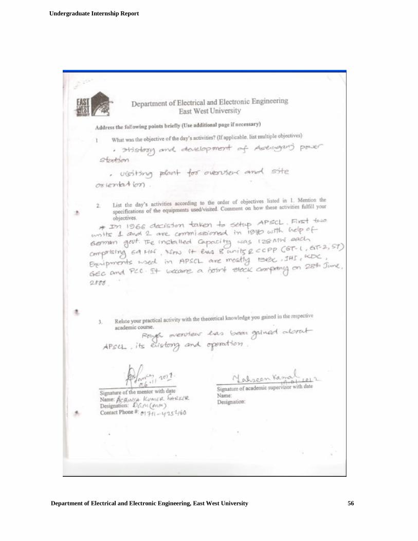
Undergraduate Internship Report
Department of Electrical and Electronic Engineering, East West University 56

Undergraduate Internship Report
Department of Electrical and Electronic Engineering, East West University 57

Undergraduate Internship Report
Department of Electrical and Electronic Engineering, East West University 58

Undergraduate Internship Report
Department of Electrical and Electronic Engineering, East West University 59
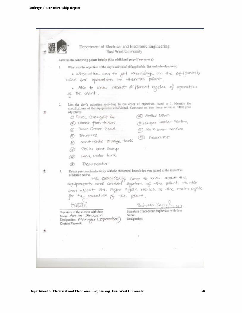
Undergraduate Internship Report
Department of Electrical and Electronic Engineering, East West University 60

Undergraduate Internship Report
Department of Electrical and Electronic Engineering, East West University 61

Undergraduate Internship Report
Department of Electrical and Electronic Engineering, East West University 62

Undergraduate Internship Report
Department of Electrical and Electronic Engineering, East West University 63

Undergraduate Internship Report
Department of Electrical and Electronic Engineering, East West University 64
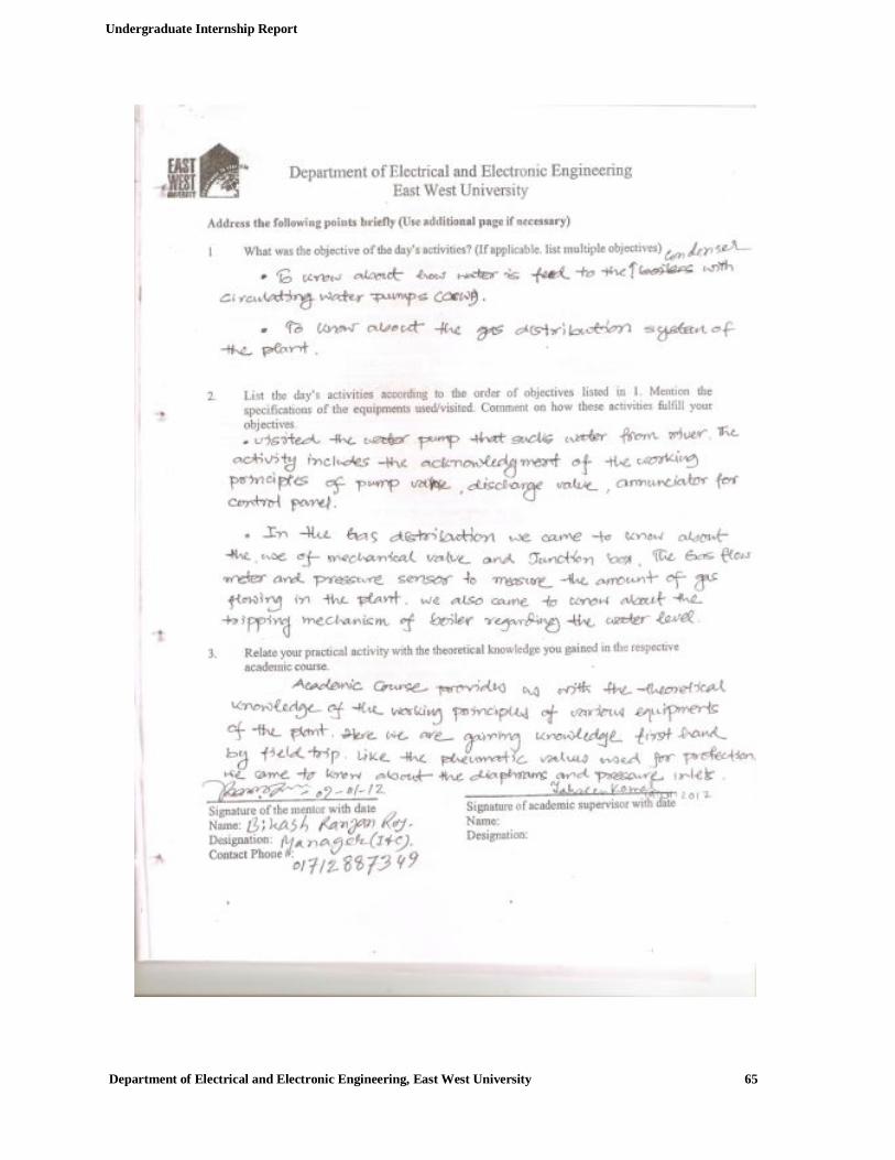
Undergraduate Internship Report
Department of Electrical and Electronic Engineering, East West University 65

Undergraduate Internship Report
Department of Electrical and Electronic Engineering, East West University 66
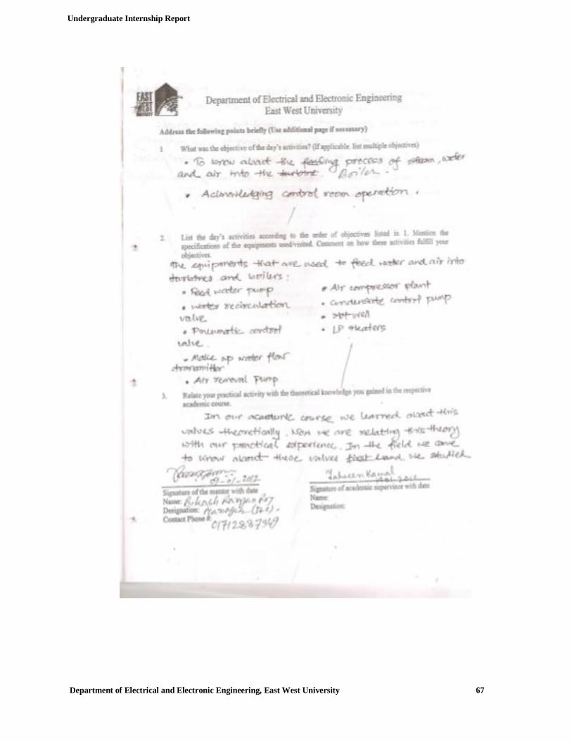
Undergraduate Internship Report
Department of Electrical and Electronic Engineering, East West University 67

Undergraduate Internship Report
Department of Electrical and Electronic Engineering, East West University 68

Undergraduate Internship Report
Department of Electrical and Electronic Engineering, East West University 69

Undergraduate Internship Report
Department of Electrical and Electronic Engineering, East West University 70

Undergraduate Internship Report
Department of Electrical and Electronic Engineering, East West University 71

Undergraduate Internship Report
Department of Electrical and Electronic Engineering, East West University 72

Undergraduate Internship Report
Department of Electrical and Electronic Engineering, East West University 73

Undergraduate Internship Report
Department of Electrical and Electronic Engineering, East West University 74
Undergraduate Internship Report
Department of Electrical and Electronic Engineering, East West University 75

Undergraduate Internship Report
Department of Electrical and Electronic Engineering, East West University 76
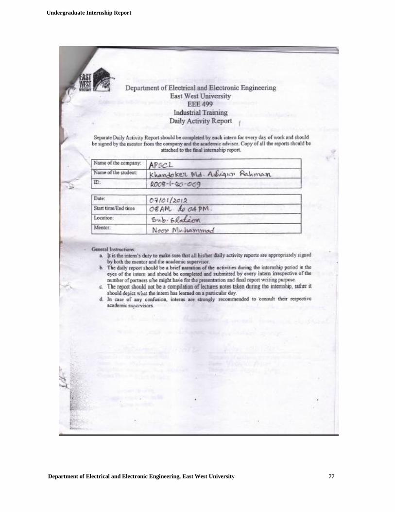
Undergraduate Internship Report
Department of Electrical and Electronic Engineering, East West University 77

Undergraduate Internship Report
Department of Electrical and Electronic Engineering, East West University 78

Undergraduate Internship Report
Department of Electrical and Electronic Engineering, East West University 79

Undergraduate Internship Report
Department of Electrical and Electronic Engineering, East West University 80

Undergraduate Internship Report
Department of Electrical and Electronic Engineering, East West University 81

Undergraduate Internship Report
Department of Electrical and Electronic Engineering, East West University 82

Undergraduate Internship Report
Department of Electrical and Electronic Engineering, East West University 83

Undergraduate Internship Report
Department of Electrical and Electronic Engineering, East West University 84

Undergraduate Internship Report
Department of Electrical and Electronic Engineering, East West University 85

Undergraduate Internship Report
Department of Electrical and Electronic Engineering, East West University 86


![Internship Handbook - Arkansas State Universitymyweb.astate.edu/.../2012_MSE_Internship_Handbook.pdf · Internship Handbook [Type text] Page 5 Overview of the Internship The internship](https://img.pdfslide.net/doc/110x75/5f0d5b6a7e708231d439f328/internship-handbook-arkansas-state-internship-handbook-type-text-page-5-overview.jpg)