Embed Size (px)
Citation preview
7
Interoperability Among Heterogeneous Networks for Future
Aeronautical Communications
Kai Xu, Prashant Pillai, Yim Fun Hu and Muhammad Ali School of Engineering, Design and Technology, University of Bradford
United Kingdom
1. Introduction
Air traffic in Europe is expected to double by 2025 according to the last forecast of
EUROCONTROL, with an average growth of 2.7%-3.7% per year. On a worldwide basis, the
number of passengers is expected to grow by 4.5% per year over the same timeframe. Future
passenger and freight fleets will bring higher efficiency and improved environmental
performance, and will allow people all around the world to benefit from the essential
connections that only air transport can deliver. (European Organisation for the Safety of Air
Navigation [EUROCONTROL], 2006)
Till recently Aeronautical Telecommunication Network (ATN) communications predominantly across continental regions used narrowband Very High Frequency (VHF) voice systems along with digital data links like the VHF Digital Link (VDL) Mode 2 (ICAO, 2001) and Aircraft Communications Addressing and Reporting System (ACARS) (ARINC, 2011). Such narrowband air-ground data link technologies have several limitations like the susceptibility to access collisions, lack of data prioritization mechanism at the sub-network level and also the vulnerability of jamming in narrowband communication channels. Hence, other High Frequency (HF) radio link technology like the ARINC GLOBALink (Homans, 2002) and also satellite based system like the INMARSAT SwiftBroadband systems have been used to provide voice and data communications between the aircraft and the ground control centres (EUROCONTROL, 2006). A detailed study on the various communications systems suitable for Air Traffic Management (ATM) systems was carried out by the Federal Aviation Administration (FAA) and EUROCONTROL with the support of NASA (NASA, 2005). It highlighted the advantages and disadvantages of the various communications systems and showed that it is important for the future ATN communication systems to provide fast, high-speed and high-data rate reliable communications not only between the aircraft and ground infrastructure but also between airplanes directly. Hence it is envisaged that in order to provide the most efficient form of reliable ATM communications, different heterogeneous networks need to be adopted. It is also envisaged that future aeronautical communication systems would be able to simultaneously operate the different radio communication technologies. The different technologies will provide various advantages and provide the flexibility to the system to provide very high reliability. Hence different data i.e. Air Traffic Service (ATS), Airline Operation Centre (AOC), Airline Administrative
www.intechopen.com
Future Aeronautical Communications
148
communication (AAC) and Aeronautical Passenger Communications (APC) can be sent over different radio technologies depending on the Quality of Service (QoS) and security requirements of the data.
2. Wireless digital data links for future aeronautical communications
The growing need to efficiently manage airspace for increased traffic loads will require new
and more capable communications systems. The joint EUROCONTROL/FAA technology
assessment study, known as the Action Plan 17 - Future Communications Study (FCS),
made specific recommendations for data communications technologies in VHF, C, and L
bands that were endorsed by the FAA, EUROCONTROL, and International Civil Aviation
Organization (ICAO). (EUROCONTROL/FAA, 2007)
2.1 VHF
In the aeronautical communications, Air Traffic Control (ATC) is a very important service
provided by ground-based controllers who direct aircraft on the ground and in the air. VHF
radio is used by the Ground Control for monitoring and controlling any aircraft, vehicle or
person walking or working in the specific areas, such as taxiways, runways and departure
gate, to have clearance. This requires most aircrafts to have VHF radios. VHF is the radio
frequency ranges from 30MHz to 300MHz. Common uses for VHF are radio/television
broadcast, ATC communications and air navigation systems.
The VHF Digital Link (VDL) communications system is one of aircraft-to-ground
subnetworks that may be used to support data communications across the ATN between
aircraft-based application processes and their ground-based peer processes. The digital
communications protocols are employed on the devices using VHF radios to support data
communication functions. The International Telecommunication Union (ITU) assigns the
band 118MHz to 137MHz to be used by VDL for the aeronautical services. A range of
International Civil Aviation Organization (ICAO) standards are defined by Aeronautical
Mobile Communications Panel (AMCP):
ICAO VDL Mode 1: is defined for validation purposes. The VHF analog radio is used before VHF Digital Radio implementation was completed.
ICAO VDL Mode 2: is the main version of VDL. This is the only mode being implemented operationally to support Controller Pilot Data Link Communications CPDLC (i.e. an ATC service). The VDL2 system is based on the OSI reference model, therefore the lower three layers: the physical layer, the data link layer and the subnetwork layer, are specified to provide code transparent communications between the ATN systems. The physical layer provides services to activate, maintain and de-activate connections for bit transmission in the data link layers. The link layer is responsible for transferring information from one network entity to another. The subnetwork layer is responsible for controlling the data packet flow with respect to duplicate, lost or invalid packets. A Subnetwork Dependent Convergence Function (SNDCF) is required to provide a transparent connectionless mode service to the ATN internetworking protocol, as the VDL2 is a connection-mode subnetwork access protocol. (ICAO, 2001)
ICAO VDL Mode 3: defines a protocol providing aircraft with both data and digitized voice communications that was defined by the US FAA.
www.intechopen.com
Interoperability Among Heterogeneous Networks for Future Aeronautical Communications
149
ICAO VDL Mode 4: specifies a protocol enabling aircraft to exchange data with ground stations and other aircraft.
From the aeronautical mobile communications evolution overview carried out by, the VHF analog voice communications will be maintained and operated throughout the time frame (2005 - 2030) both in the European and in the U.S. EUROCONTROL is progressing toward the full implementation the carriage and operation of 8.33 kHz capable equipment below FL195 in 2013. In addition to legacy ACARS services, Europe will use VDL Mode 2 in the VHF band for the ATC and AOC data link services. Air traffic management services that operate on VDL Mode 2 will be maintained throughout the time span, enhanced as needed to support safety related services in the U.S. (EUROCONTROL/FAA, 2007).
2.2 DVB-S2
Digital video broadcasting-satellite-second generation also known as DVB-S2 is a successor for the well-known digital video broadcast standard DVB-S. The DVB-S2 is based on Digital Satellite News Gathering (DSNG) and DVB-S standards used by mobile stations for transmitting multimedia data to their home television stations from remote locations all over the world. The DVB-S2 added two new and significant features which are: A modern Low-Density-Parity-Check (LDPC) powerful coding scheme and secondly a Variable Coding & Modulation (VCM) and adaptive coding & modulation (ACM) parameters which enable dynamically changing transmission parameters to optimize bandwidth utilization. Additional features which DVB-S2 provides are improved modulation schemes up to 32APSK (ETSI, 2009b), generic transport mechanism for IP packet data also including MPEG-4 video and audio streams support as backward compatibility with DVB-S MPEG-2 TS based transmission and additional code rates. The DVB-S2 standard boasts that DVB-S2 has almost 30% performance gain over DVB-S using the same satellite transponder bandwidth and emitted signal power. HDTV service can now be delivered using the same capacity which supported earlier DVB-S based SDTV service using the improved techniques of video compression in DVB-S2. Several technological advancements have been achieved in the last decade for satellite broadcasting, which has given rise to the need of DVB-S2. (ETSI, 2009b) The DVB-S2 standard attains high data transmission capacity as compared to first
generation system (DVB-S) as DVB-S2 has less complex design for hardware and software
level implementation of receiver, provides an enhanced flexibility. DVB-S2 takes advantage
of the recent advancement in modulation and channel coding techniques to maintain
equilibrium between performance and complexity. Implementation of such novel
techniques to achieve target goals, enable DVB-S2 to raise 30% capacity as compared to
DVB-S by utilizing the same transmission conditions. The DVB-S2 can provide Constant
Coding and Modulation (CCM) and Adaptive Coding Modulation (ACM). (ETSI, 2009b)
The DVB-S2 enables high flexibility to deal with characteristics of all existing satellite
transponders with a large variety of spectrum efficiencies and associated C/N requirements.
Supporting format for DVB-S2 is not only limited to MPEG-2 multimedia data source
coding but it is efficiently designed to deal with a variety of video, audio and data formats
including the formats which DVB projects is currently developing for the future application.
The DVB-S2 system is optimized for the broadband application scenarios such as: Interactive services. The internet access can be a good example of interactive service. DVB-S2 is envisioned to provide the interactive services especially to the mobile devices roaming
www.intechopen.com
Future Aeronautical Communications
150
in the remote places. As DVB-S and DVB-S2 both provide the transmission in forward direction only there is no detailed mechanism specified in the standard documents of DVB-S and DVB-S2 about the return direction. Therefore the interactive services can be established using return link as terrestrial or other satellite links. Generic stream format or transport stream format are utilized for data services transportation (ETSI, 2009b).
2.3 BGAN
In December 1999, INMARSAT’s Board of Directors approved the development of fourth generation of satellites for the Broadband Global Aeronautical Network (BGAN) project. The INMARSAT-4 satellites comprise of two GEO satellites, which were initially located over the Indian Ocean Region (64ºE) and Atlantic Ocean Region (53ºW) respectively, to provide communication service to the Mobile Terminals (MT). A third satellite (98ºW) was launched in 2008. Each INMARSAT-4 satellite weighs 3 tonnes and supports approximately 200 spot beams. It provides transparent amplification for the BGAN communications (user plane and control plane). Transmission between the RNC and satellite is via the C band, whereas transmission between the satellite and MTs is via the L band. (INMARSAT, 2003) The INMARSAT BGAN is intended to form part of the satellite component of the Third Generation (3G) IMT-2000/Universal Mobile Telecommunications System (UMTS). Among the design objectives is the interoperability with an industry standard 3G Core Network and the re-use of the UMTS Non Access Stratum (NAS) layers. The BGAN system adopted the standard UMTS architecture in the core network but uses an INMARSAT proprietary air interface –the INMARSAT Air Interface 2 (IAI-2), which provides a complete Access Stratum Protocol Stack and Physical Layer optimised for the geo-stationary satellite environment. The air interface is based on TDM and TDMA/FDM schemes in forward direction and return direction respectively (INMARSAT, 2003). BGAN is the first system to provide guaranteed data rates on demand. It is also the first
mobile communication system to provide both voice and broadband mobile communication
services on a global area, where two GEO satellites of BGAN system will cover 85 percent of
the earth’s surface. The system network architecture has the capability to provide UMTS
compatible services and both circuit switched and packet switched services. The BGAN MTs
are the lightweight, portable satellite terminals, which are easy to carry, simple to setup for
use, can deliver data rates of up to half a megabit. In order to achieve high transmission
efficiency and flexibility, it is possible to adapt the bandwidth, coding rate according to the
MT’s class and channel conditions. In the BGAN baseline system, 3 classes of MTs are
supported with different maximum transmission rates of 432 Kbps, 432 Kbps, and 216 Kbps
respectively when receiving data and maximum transmission rates of 432 Kbps, 144 Kbps
and 72 Kbps respectively when transmitting. All MTs have the capability of allocating
bandwidth dynamically in each direction. At present, the number of MT classes is being
extended to support additional services in the BGAN-X project. (Jilg, 2002; ESA, 2003;
INMARSAT, 2003)
BGAN constellation aims to support existing aeronautical safety services and INMARSAT has made a Public Service Agreement (PSA) commitment to ICAO. In March 2006, Thrane & Thrane, the world leading INMARSAT satellite communications company, entered a BGAN Extension contract with INMARSAT. The contract covers an upgrade of the RAN Satellite Access Stations to also handle the planned broadband services for aeronautical (SwiftBroadband) usage in providing voice and data services.
www.intechopen.com
Interoperability Among Heterogeneous Networks for Future Aeronautical Communications
151
2.4 AeroMACS
The Aeronautical Mobile Airport Communications System (AeroMACS) is a new airport communication system. This system is jointly identified and recommended based on IEEE 802.16e system by the EUROCONTROL and American Federal Aviation Administration (FAA) to provide the solution for dedicated aeronautical communication services on the airport surface. The EUROCONTROL and American Federal Aviation Administration (FAA) have established the first Memorandum of Cooperation (MoC) in 1986 (EUROCONTROL, 2001). To accommodate future growth in surface applications, the new airport radio local area network should operate in the additional spectrum in C-band (5091 – 5150 MHz), which is co-allocated in the World Radio Communications Conference 2007 (WRC07). It is identified that the AeroMACS radio technology is based on the IEEE 802.16e standard (IEEE, 2009a), which is best suitable for short-range and mobile broadband data communications. The AeroMACS technology is well matched to the airport surface environment in terms of capability and performance. The AeroMACS standards development activities, such as to propose an aviation specific standard and to evaluate/validate the performance of the standard etc., have been planned under the EUROCONTROL/FAA AP 17. (EUROCONTROL/FAA, 2007) As the development of AeroMACS is based on the IEEE 802.16e standard, it is believed by EUROCONTROL that no (or minimum) modifications or additions will be needed to the existing IEEE organisations’ profiles according to the aviation special operational requests. But EUROCONTROL is still looking into the need for establishing new system profiles which shall be optimised for aviation needs. The existing IEEE profiles are split up into two parts: System Profiles - specifying subsets of mandatory and optional physical and MAC layer features from the standard and the Certification Profiles - specifying the channel bandwidth, operating frequencies and duplexing method. Because the AeroMACS radio will operate in dedicated aeronautical spectrum (5091 – 5150 MHz), it is need to establish a new Certification Profile. (EUROCONTROL, 2009) IEEE 802.16e standard is the most popular commercial implementation of the 802.16 family of standards, which is written by a working group established by IEEE Standards Board. While WirelessMAN is the official name of the 802.16 family, it is commercially known as Worldwide Interoperability for Microwave Access (WiMAX). The name is coined by the WiMAX Forum, which is an industry alliance to promote and certify compatibility and interoperability of broadband wireless products based on the IEEE 802.16 standards. IEEE 802.16e (abbreviation of 802.16e-2005) concluded in 2005, specifies mechanisms to support mobility. It is therefore also known as Mobile WiMAX. Because of its advanced transmission capacities of between 34 Mbits/s and 1Gbit/s, WiMAX networks are able to provide mobile broadband or at home broadband connectivity across whole cities or countries.
3. Interoperability among heterogeneous networks
As previously discussed, it is envisaged that future ATN system will comprise of heterogeneous systems. Hence it would be important to monitor and control these various systems efficiently and also provide means to handover active sessions between these different radio technologies. Currently, the different radio access networks work independently and have limited or in most cases no interaction amongst themselves. However, to support efficient control and seamless vertical handovers, future networks need to interact and communicate together. Recently, some standardisation work has been
www.intechopen.com
Future Aeronautical Communications
152
carried out in order to define mechanism and protocols to support interworking between different networks. The following subsections provide an overview of two existing standards, namely the ETSI Broadband Satellite Multimedia (BSM) SI-SAP (Satellite Independent – Service Access Point) and the IEEE802.21 Media Independent Handover framework that provide means to support interoperability among heterogeneous networks. Both standards consider the separation of technology-independent upper layers from the technology-dependent lower layers to enable interoperability among heterogeneous networks. The BSM SI-SAP concentrates on the separation of upper layer functions from lower layer functions for satellite systems whereas the MIH framework defines media-independent functions for handover between heterogeneous mobile and wireless networks.
3.1 Broadband satellite multimedia
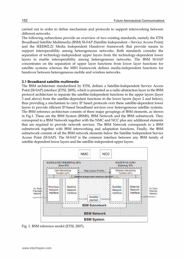
The BSM architecture standardised by ETSI, defines a Satellite-Independent Service Access Point (SI-SAP) interface (ETSI, 2005), which is presented as a radio abstraction layer in the BSM protocol architecture to separate the satellite-independent functions in the upper layers (layer 3 and above) from the satellite-dependant functions in the lower layers (layer 2 and below), thus providing a mechanism to carry IP based protocols over these satellite-dependent lower layers to provide efficient IP-based broadband services over heterogeneous satellite systems. The BSM reference architecture consists of three major groupings of BSM elements, as shown in Fig.1. These are the BSM System (BSMS), BSM Network and the BSM subnetwork. They correspond to a BSM Network together with the NMC and NCC plus any additional elements that are required to provide network services. The BSM Network corresponds to a BSM subnetwork together with BSM interworking and adaptation functions. Finally, the BSM subnetwork consists of all the BSM network elements below the Satellite Independent Service Access Point (SI-SAP). The SI-SAP is the common interface between any BSM family of satellite dependent lower layers and the satellite independent upper layers.
Fig. 1. BSM reference model (ETSI, 2007).
www.intechopen.com
Interoperability Among Heterogeneous Networks for Future Aeronautical Communications
153
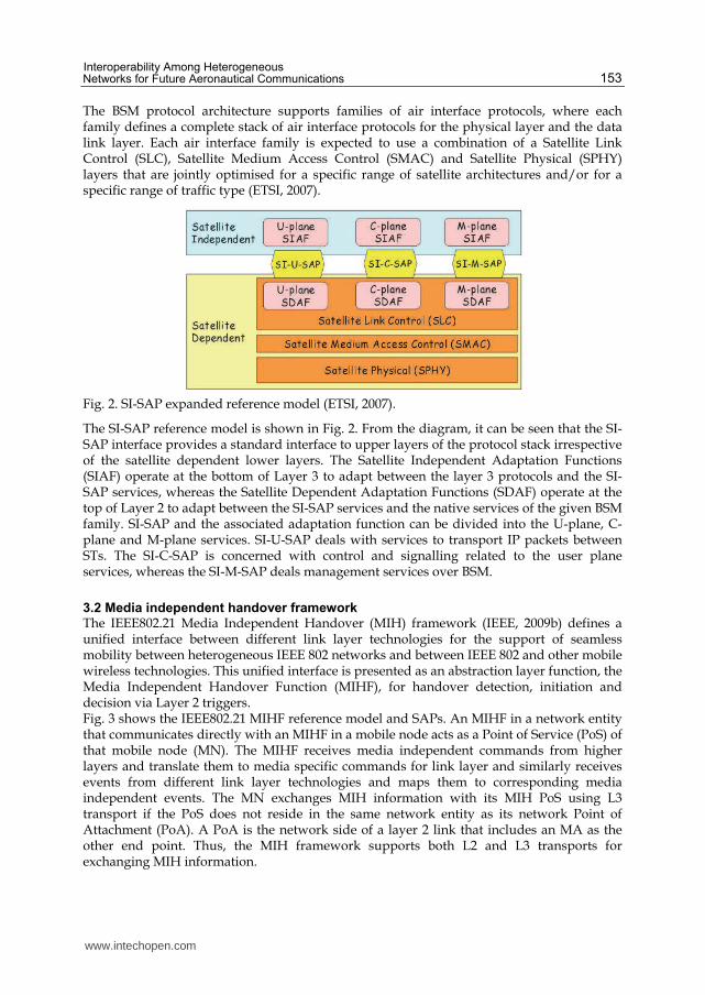
The BSM protocol architecture supports families of air interface protocols, where each family defines a complete stack of air interface protocols for the physical layer and the data link layer. Each air interface family is expected to use a combination of a Satellite Link Control (SLC), Satellite Medium Access Control (SMAC) and Satellite Physical (SPHY) layers that are jointly optimised for a specific range of satellite architectures and/or for a specific range of traffic type (ETSI, 2007).
Fig. 2. SI-SAP expanded reference model (ETSI, 2007).
The SI-SAP reference model is shown in Fig. 2. From the diagram, it can be seen that the SI-SAP interface provides a standard interface to upper layers of the protocol stack irrespective of the satellite dependent lower layers. The Satellite Independent Adaptation Functions (SIAF) operate at the bottom of Layer 3 to adapt between the layer 3 protocols and the SI-SAP services, whereas the Satellite Dependent Adaptation Functions (SDAF) operate at the top of Layer 2 to adapt between the SI-SAP services and the native services of the given BSM family. SI-SAP and the associated adaptation function can be divided into the U-plane, C-plane and M-plane services. SI-U-SAP deals with services to transport IP packets between STs. The SI-C-SAP is concerned with control and signalling related to the user plane services, whereas the SI-M-SAP deals management services over BSM.
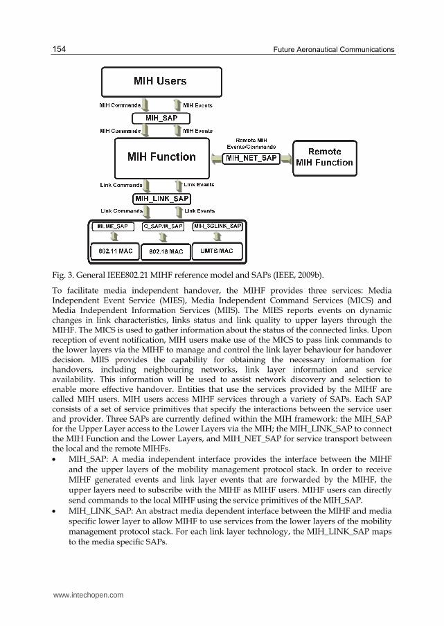
3.2 Media independent handover framework The IEEE802.21 Media Independent Handover (MIH) framework (IEEE, 2009b) defines a unified interface between different link layer technologies for the support of seamless mobility between heterogeneous IEEE 802 networks and between IEEE 802 and other mobile wireless technologies. This unified interface is presented as an abstraction layer function, the Media Independent Handover Function (MIHF), for handover detection, initiation and decision via Layer 2 triggers. Fig. 3 shows the IEEE802.21 MIHF reference model and SAPs. An MIHF in a network entity that communicates directly with an MIHF in a mobile node acts as a Point of Service (PoS) of that mobile node (MN). The MIHF receives media independent commands from higher layers and translate them to media specific commands for link layer and similarly receives events from different link layer technologies and maps them to corresponding media independent events. The MN exchanges MIH information with its MIH PoS using L3 transport if the PoS does not reside in the same network entity as its network Point of Attachment (PoA). A PoA is the network side of a layer 2 link that includes an MA as the other end point. Thus, the MIH framework supports both L2 and L3 transports for exchanging MIH information.
www.intechopen.com
Future Aeronautical Communications
154
Fig. 3. General IEEE802.21 MIHF reference model and SAPs (IEEE, 2009b).
To facilitate media independent handover, the MIHF provides three services: Media Independent Event Service (MIES), Media Independent Command Services (MICS) and Media Independent Information Services (MIIS). The MIES reports events on dynamic changes in link characteristics, links status and link quality to upper layers through the MIHF. The MICS is used to gather information about the status of the connected links. Upon reception of event notification, MIH users make use of the MICS to pass link commands to the lower layers via the MIHF to manage and control the link layer behaviour for handover decision. MIIS provides the capability for obtaining the necessary information for handovers, including neighbouring networks, link layer information and service availability. This information will be used to assist network discovery and selection to enable more effective handover. Entities that use the services provided by the MIHF are called MIH users. MIH users access MIHF services through a variety of SAPs. Each SAP consists of a set of service primitives that specify the interactions between the service user and provider. Three SAPs are currently defined within the MIH framework: the MIH_SAP for the Upper Layer access to the Lower Layers via the MIH; the MIH_LINK_SAP to connect the MIH Function and the Lower Layers, and MIH_NET_SAP for service transport between the local and the remote MIHFs.
MIH_SAP: A media independent interface provides the interface between the MIHF and the upper layers of the mobility management protocol stack. In order to receive MIHF generated events and link layer events that are forwarded by the MIHF, the upper layers need to subscribe with the MIHF as MIHF users. MIHF users can directly send commands to the local MIHF using the service primitives of the MIH_SAP.
MIH_LINK_SAP: An abstract media dependent interface between the MIHF and media specific lower layer to allow MIHF to use services from the lower layers of the mobility management protocol stack. For each link layer technology, the MIH_LINK_SAP maps to the media specific SAPs.
www.intechopen.com
Interoperability Among Heterogeneous Networks for Future Aeronautical Communications
155
MIH_NET_SAP: An abstract media dependent interface of the MIHF, provides transport services over the data plane on the local node to support the exchange of MIH information and messages with remote MIHFs. Transport services provided by the MIH_NET_SAP can use either L2 or L3 signalling.
4. The SANDRA radio resource management (RRM) framework
4.1 SANDRA network architecture
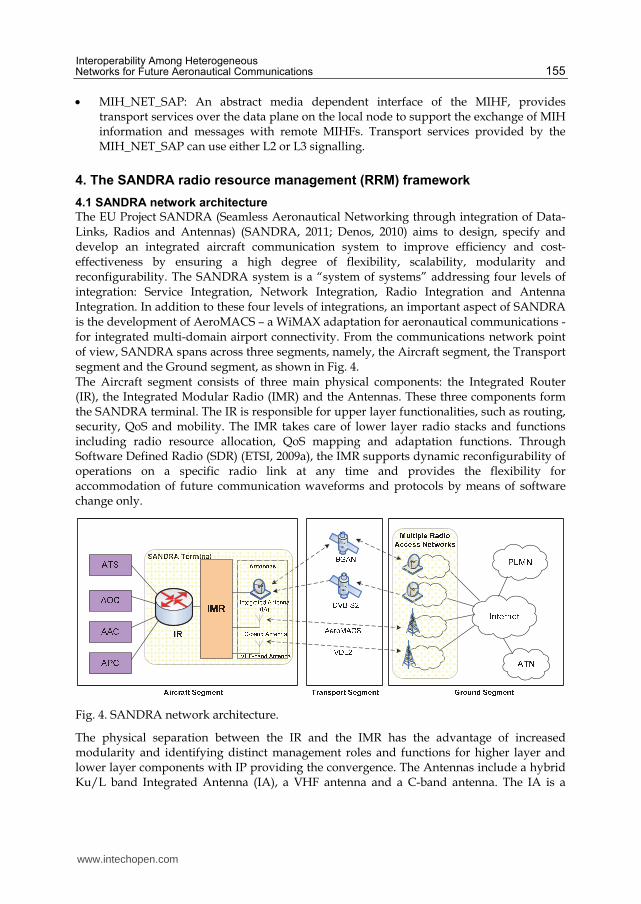
The EU Project SANDRA (Seamless Aeronautical Networking through integration of Data-Links, Radios and Antennas) (SANDRA, 2011; Denos, 2010) aims to design, specify and develop an integrated aircraft communication system to improve efficiency and cost-effectiveness by ensuring a high degree of flexibility, scalability, modularity and reconfigurability. The SANDRA system is a “system of systems” addressing four levels of integration: Service Integration, Network Integration, Radio Integration and Antenna Integration. In addition to these four levels of integrations, an important aspect of SANDRA is the development of AeroMACS – a WiMAX adaptation for aeronautical communications - for integrated multi-domain airport connectivity. From the communications network point of view, SANDRA spans across three segments, namely, the Aircraft segment, the Transport segment and the Ground segment, as shown in Fig. 4. The Aircraft segment consists of three main physical components: the Integrated Router (IR), the Integrated Modular Radio (IMR) and the Antennas. These three components form the SANDRA terminal. The IR is responsible for upper layer functionalities, such as routing, security, QoS and mobility. The IMR takes care of lower layer radio stacks and functions including radio resource allocation, QoS mapping and adaptation functions. Through Software Defined Radio (SDR) (ETSI, 2009a), the IMR supports dynamic reconfigurability of operations on a specific radio link at any time and provides the flexibility for accommodation of future communication waveforms and protocols by means of software change only.
Fig. 4. SANDRA network architecture.
The physical separation between the IR and the IMR has the advantage of increased modularity and identifying distinct management roles and functions for higher layer and lower layer components with IP providing the convergence. The Antennas include a hybrid Ku/L band Integrated Antenna (IA), a VHF antenna and a C-band antenna. The IA is a
www.intechopen.com
Future Aeronautical Communications
156
hybrid Ku/L band SatCom antenna to enable an asymmetric broadband link. The Ku-band system is used for receive mode only to reduce the number of antennas and the L-band will use the INMARSAT Swift Broadband link capable of both transmit and receive functions. The VHF antenna will be used to provide transmit and receive links for VDL2 mode ATC and AOC voice communications services. The C-band antenna will be used for AeroMACS to enable aircraft-airport and inter-domain airport connectivity. The various end-systems i.e. ATS, AOC, AAC and APC (SANDRA, 2011) are all connected to the IR. In the transport segment, four radio transport technologies are considered, namely, VDL mode 2 (ICAO, 2001) in VHF band for legacy systems and applications, BGAN (INMARSAT, 2011) in L-band, DVB-S2 (ETSI, 2009b) in Ku-band for passenger communication services and AeroMACS (a WiMAX equivalent for aeronautics communications) in C-band providing airport link for short range airport ATC communications. These transport technologies provides connectivity between the aircraft segment and the ground segment supported by the IMR and their corresponding Radio Access Networks (RANs) on ground. The selection of the appropriate transport network is made within the SANDRA connection manager (CM) that spans across the IR and the IMR based upon applications, policies, regulatory constraints, service availability, quality of service and other factors. The Ground segment consists of multiple operators; multiple Radio Access Networks (RANs) and their corresponding core networks, the ATN, the Internet and possibly the Public Land Mobile Network (PLMN, for passenger communications). The RANs can also be connected directly to the ATN and the PLMN on the ground. In order to provide mobility service and security services for aeronautical communications, functional components such as the mobility server, security and authentication server are required in the ground segment to provide corresponding mobility information services as well as security services. These components will be provided by the ATS/AOC/AAC and APC service providers of the ATN on ground.
4.2 Overview of RRM The efficient utilisation of common radio resources is an important aspect in the wireless communication networking. The goal of Radio Resource Management (RRM) is to optimize bandwidth utilisation and Quality of Service, in the presence of traffic flows generated by services with different requirements. QoS can refer to the capability of a telecommunication system to provide better services to user traffic. Whenever resources or their modifications are requested, the goal of RRM is to optimise resource utilisation and at the same time satisfy the requested QoS requirements while trying to maintain a certain degree of fairness among all users. Cross-layer RRM techniques that consider the cooperation of two or more protocol layers have been used to optimise the system usage in run time to guarantee good performance of the overall system in order to fulfil the user performance requirements. (Giambene, 2007) An efficient dynamic RRM scheme can optimise the system usage in run time to guarantee good performance of the overall system by maximising some performance indicators, such as the overall network throughput, the resource utilization and total network earning, and at the same time to minimise other indicators, such as the end-to-end (ETE) delay, the packet discard rate (PDR), the call dropping rate and the signal-to-noise ratio. RRM schemes can include a set of service control functions, which are categorised into network based functions and connection based functions. Network based functions include admission
www.intechopen.com
Interoperability Among Heterogeneous Networks for Future Aeronautical Communications
157
control (AC), load control (LC), packet scheduler (PS) and resource manager (RM); whereas connection based functions include power control (PC) and handover control (HC):
Admission control function is to grant/deny connections’ access to the network based on whether there are sufficient free resources by taking into account predefined criteria (QoS requirements). The AC process occurs when new connection is set up, as well during handovers and service modification. It is especially important in congestion control and in QoS provisioning for wireless networks. May AC algorithms, like conventional, expert knowledge and intelligent predictive/learning algorithms, have been proposed to resolve radio resource allocation problem.
Load control is responsible to optimise the capacity of the system and to prevent overloading situations. This function enables the estimation of the traffic load condition and load balancing mechanism to be carried out. It is particularly important in managing system overload situations (i.e. when the system load exceeds the threshold limit) in order that the system load can be maintained in a feasible manner.
Packet scheduling handles all traffic generated by packet data users and decides the order of packet transmission, when a packet transmission is initiated and what bit rate and resource will be allocated. This provides multiplexing functions for different traffic mix, taking into account the QoS constraints such as bandwidth requirement and traffic priority. The nature of a scheduling framework can greatly impacts the QoS levels that can be provided in the system. Much research related to scheduling techniques has been done focused on the latest wireless technologies to support diverse QoS requirements for a wide range of applications, for example WiMAX network, Orthogonal Frequency-Division Multiple Access (OFDMA) wireless system and shared-medium wireless network etc (Fantacci et al., 2009; Kumar et al., 2009).
Resource manager includes the estimation of the required number of transport and
physical channels for the support of various traffic types and the actual radio channel
allocation based on the traffic load condition. Many research works have been carried
out to investigate suitable resource access strategies for efficient radio bandwidth
assignment. Four primary strategies are identified: fixed assignment, demand
assignment, free assignment and random access. Many hybrid resource allocation
strategies have been proposed by combining the good advantages of the different
strategies.
Power control transmits the signal with the lowest possible power level, but at the same
time, maintaining the required signal quality to maximise network capacity.
Determining the transmitter power level is quite a challenging task due to the dynamic
variation of the radio channel. To achieve this, power control functions have been well
investigated and many efficient algorithms have been developed to accurately control
the transmission power, such as centralised, distributed, synchronous, asynchronous,
interactive and non-interactive methods.
Handover control function provides the ability for the user devices to change their access methods to another network in order to maintain connectivity when their environment changes. Three main phases in handover: initiation, decision and execution, are processed to ensure call/session continuity. If a handover is performed between two heterogeneous networks, a handover at the network layer making use of Mobile IP is normally used to enable communication and signalling between the two networks through IP. An important aspect of handover control is to ensure that QoS
www.intechopen.com
Future Aeronautical Communications
158
guaranteed by the serving network can be met by the target network (network to which the call/session is to be handed over). A mapping between the QoS parameters at the IP layer and those supported by the bearer services in the radio access networks has to be made.
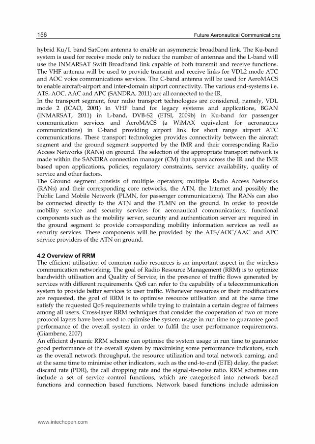
4.3 Software defined radio The components in a radio communication system are typically implemented in hardware. A Software Defined Radio (SDR) system implements the components instead by means of software computing device. The future of telecommunications is anticipated to provide great variety of services over a multitude of Radio Access Technologies (RATs). To achieve this aim, it is required that the future system is to support heterogeneity in wireless access technologies, comprising different services, device capabilities, and so on. The SDR technology can provide hardware reconfiguration ability and software programmability by introducing the open architecture to the programmable digital radio. The architecture is able to maintain an independency between the hardware function module and software function module. With the architecture, the SDR technology can reconstruct the application software in one common hardware platform in order to flexibly manager with the various wireless technologies with the purposes of increasing the frequency use efficiency and improving QoS. This technology is expected to form the new framework of the wireless telecommunications in the future.
Fig. 5. The SDR-enabled RRM Functional Architecture for the SANDRA Terminal.
www.intechopen.com
Interoperability Among Heterogeneous Networks for Future Aeronautical Communications
159
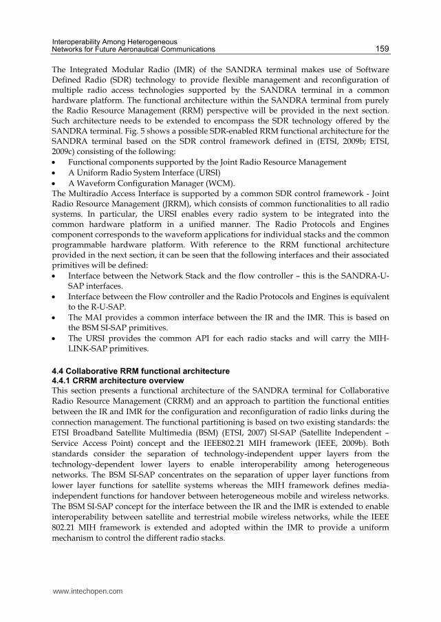
The Integrated Modular Radio (IMR) of the SANDRA terminal makes use of Software Defined Radio (SDR) technology to provide flexible management and reconfiguration of multiple radio access technologies supported by the SANDRA terminal in a common hardware platform. The functional architecture within the SANDRA terminal from purely the Radio Resource Management (RRM) perspective will be provided in the next section. Such architecture needs to be extended to encompass the SDR technology offered by the SANDRA terminal. Fig. 5 shows a possible SDR-enabled RRM functional architecture for the SANDRA terminal based on the SDR control framework defined in (ETSI, 2009b; ETSI, 2009c) consisting of the following:
Functional components supported by the Joint Radio Resource Management
A Uniform Radio System Interface (URSI)
A Waveform Configuration Manager (WCM). The Multiradio Access Interface is supported by a common SDR control framework - Joint Radio Resource Management (JRRM), which consists of common functionalities to all radio systems. In particular, the URSI enables every radio system to be integrated into the common hardware platform in a unified manner. The Radio Protocols and Engines component corresponds to the waveform applications for individual stacks and the common programmable hardware platform. With reference to the RRM functional architecture provided in the next section, it can be seen that the following interfaces and their associated primitives will be defined:
Interface between the Network Stack and the flow controller – this is the SANDRA-U- SAP interfaces.
Interface between the Flow controller and the Radio Protocols and Engines is equivalent to the R-U-SAP.
The MAI provides a common interface between the IR and the IMR. This is based on the BSM SI-SAP primitives.
The URSI provides the common API for each radio stacks and will carry the MIH-LINK-SAP primitives.
4.4 Collaborative RRM functional architecture 4.4.1 CRRM architecture overview
This section presents a functional architecture of the SANDRA terminal for Collaborative
Radio Resource Management (CRRM) and an approach to partition the functional entities
between the IR and IMR for the configuration and reconfiguration of radio links during the
connection management. The functional partitioning is based on two existing standards: the
ETSI Broadband Satellite Multimedia (BSM) (ETSI, 2007) SI-SAP (Satellite Independent –
Service Access Point) concept and the IEEE802.21 MIH framework (IEEE, 2009b). Both
standards consider the separation of technology-independent upper layers from the
technology-dependent lower layers to enable interoperability among heterogeneous
networks. The BSM SI-SAP concentrates on the separation of upper layer functions from
lower layer functions for satellite systems whereas the MIH framework defines media-
independent functions for handover between heterogeneous mobile and wireless networks.
The BSM SI-SAP concept for the interface between the IR and the IMR is extended to enable
interoperability between satellite and terrestrial mobile wireless networks, while the IEEE
802.21 MIH framework is extended and adopted within the IMR to provide a uniform
mechanism to control the different radio stacks.
www.intechopen.com
Future Aeronautical Communications
160
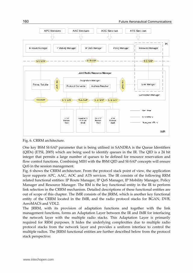
Fig. 6. CRRM architecture.
One key BSM SI-SAP parameter that is being utilised in SANDRA is the Queue Identifiers
(QIDs) (ETSI, 2005) which are being used to identify queues in the IR. The QID is a 24 bit
integer that permits a large number of queues to be defined for resource reservation and
flow control functions. Combining MIH with the BSM QID and SI-SAP concepts will ensure
QoS in the session management.
Fig. 6 shows the CRRM architecture. From the protocol stack point of view, the application
layer supports APC, AAC, AOC and ATS services. The IR consists of the following RRM
related functional entities: IP Route Manager, IP QoS Manager, IP Mobility Manager, Policy
Manager and Resource Manager. The RM is the key functional entity in the IR to perform
link selection in the CRRM mechanism. Detailed descriptions of these functional entities are
out of scope of this chapter. The IMR consists of the JRRM, which is another key functional
entity of the CRRM located in the IMR, and the radio protocol stacks for BGAN, DVB,
AeroMACS and VDL2.
The JRRM, with its provision of adaptation functions and together with the link
management functions, forms an Adaptation Layer between the IR and IMR for interfacing
the network layer with the multiple radio stacks. This Adaptation Layer is primarily
required for RRM purposes. It hides the underlying complexities due to multiple radio
protocol stacks from the network layer and provides a uniform interface to control the
multiple radios. The JRRM functional entities are further described below from the protocol
stack perspective:
www.intechopen.com
Interoperability Among Heterogeneous Networks for Future Aeronautical Communications
161
Link Manager: Performs link selection and link configuration functions and together
with the RM in the IR forms the Connection Manager (CM). The CM as a whole acts as
a MIH user in the MIH framework.
Adaptation Manager: Is primarily responsible for providing the various adaptation
functions required for proper interfacing between the IR and the radio stacks. It consists
of the following functions:
Protocol mapping: The request parameters like QoS parameters, security requirements, etc that are requested by the higher layers need to be mapped onto corresponding link-dependant parameters understood by the radio protocol stacks.
Address resolution: Different identities are used in the network layer and the radio protocol stacks to identify different connections. An address resolution table is maintained to provide correct mapping between the various identities used within the SANDRA system.
MIH Function (MIHF): The Adaptation manager also carries out a switching function equivalent to the MIH Function (MIHF) to support handover services including the Event Service (ES), Information Service (IS), and Command Service (CS), through service access points (SAPs) defined by the IEEE 802.21 MIH working group.
Packet Switcher: Is responsible for switching data packets received from the IR in the
user plane to the destined radio modules according to a packet switching table
generated and passed by the address resolver in the Adaptation Manger (AM) during
connection establishment. The packet switching table essentially contains the mapping
of the QIDs onto the Link IDs. As a result, each data packet can be switched directly to
the radio modules without passing through the AM in the user plane.
4.4.2 Collaborative RRM mechanism
The Collaborative RRM mechanism defined in SANDRA considers collaborative connection
management, collaborative QoS management and collaborative mobility management in
relation to admission control, packet scheduling and handover through cross-layer
collaboration between functional entities in the IR and the IMR. While the IR is responsible
for managing the network layer traffic flows, the IMR is responsible for the link layer
connections. The collaborating entities, the RM and the LM, are grouped into a single cross-
layer entity - the Connection Manager (CM). The relationships of the CM with the Policy
Manager (PM), the IP QoS Manager (IQM), the IP Mobility Manger (IMM), IP Route Manger
(IRM) and the AM as well as the mapping of IP Queues onto QIDs and Link IDs are
depicted in Fig. 7.
The SANDRA Sessions mechanism is used for connection management and connection
bindings between the IR and the IMR in order to provide efficient RRM and to meet the QoS
requirements. Sessions are used to map corresponding data queues within the IP layer and
the link layer. The term “session” corresponds to a single connection between a given IP
queue and a link-layer queue. There is a one-to-one mapping between the IP queues and the
sessions. In BSM, the Queue Identifier (QID) is used for mapping IP queues to BSM queues.
This QID concept has been adopted and extended within SANDRA to identify the IP queues
in the IR and its corresponding session with the IMR. Hence, each session is identified by a
unique QID.
www.intechopen.com
Future Aeronautical Communications
162
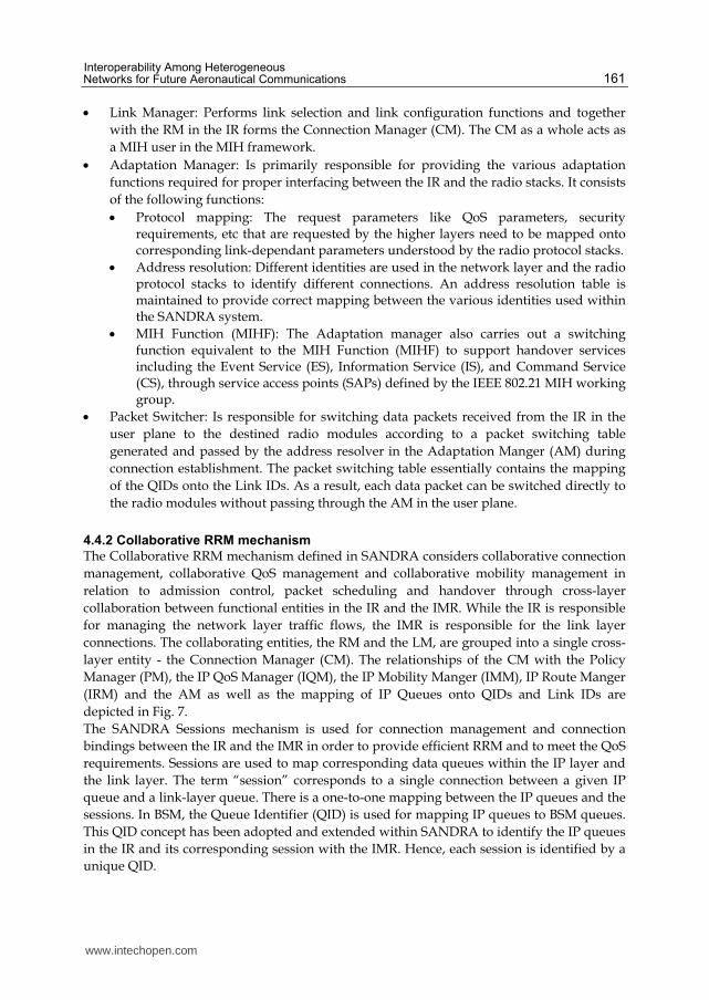
Fig. 7. Cross-layer collaborative connection management.
4.4.3 Collaborative connection management
Connection management functions including connection establishment, connection termination and connection modifications are carried out by the CM that enables decisions on network layer and link layer connections to be made by the RM in the IR and the LM in the IMR collaboratively. To establish a session for an application, the RM in the IR sends a RR to the LM, specifying the QoS parameters, user preferences, set up policy, etc. As the BSM SI-SAP interface is used between the IR and the IMR, this RR maps to the SI-C-Queue-OPEN-req message. The LM will configure the selected radio link to reserve bandwidth for the session according to the requirements specified in the RR. BSM QID is used between the IR and IMR to uniquely identify a session for the purpose of routing, scheduling, handover and session initiation/termination. Each session is mapped onto a radio specific connection identified by a Link ID used in different radio modules, such as a connection in AeroMACS or a PDP context in BGAN. As shown in Fig. 7, the PM has knowledge on flow-specific rules and policies for individual applications and end-systems. These policies may govern the decision on which radio links can be used for different flows. Such policies may be based on the type of applications, type of planes, the location of the plane and flight path, etc. It may also be based on security and regulatory requirements that may restrict these flows to be transported over a specific radio link. Flows that do not have such strict requirements specified by the policy manager may be transported over a set of available links that satisfies the application QoS. The Resource Manager in the IR may receive service requests from the applications in the higher layers specifying the QoS required by the applications. The resource manager will check with the PM to determine if there are any flow-specific rules already present for this particular applications that may be used for the suitable link selection. There are
www.intechopen.com
Interoperability Among Heterogeneous Networks for Future Aeronautical Communications
163
applications that do not explicitly send a request to the IR specifying the required QoS but will start sending the application data directly to the IR. An example is the data sent from passenger specific application (e.g. web-browser). The Resource Manager will also be responsible for managing the resources required for such traffic. As a key part of the Collaborative RRM mechanism, the Resource Manager carries out the first level of decision making. It is responsible for deciding when new resources are required, when resources are released, etc. It will also perform link selection decision upon receiving a dedicated RR for a given application. The Link Manager in the IMR is responsible for controlling the radio links and performs the second level of RRM related decision making for connection establishment. In the case of a general RR, the LM will select the most suitable link by mapping the application QoS requirements onto the resource availability and the quality of available links. The radio link that can most satisfy the QoS requirements will be selected and a general session between the IR and the selected radio link will be established.
4.4.4 Cross-layer collaborative QoS management
In relation to satisfying the QoS requirements upon a service request, the IQM in the IR will control and manage the IP Queues. On receiving data from the higher layers, the IP QoS manager performs packet classification based on the type of application and perform packet marking using Diffserv code points. Codes corresponding to the QoS requirements are added to the IP header of each packet before sending it to the IMR. The IQM in the IR also performs packet level scheduling of all incoming application packets based on their QoS requirements. The IR sees the different sessions between the IR and the IMR as different data pipes through which different data needs to be sent. Except under the situation when the IR submits a dedicated RR, data flow can be sent over any available sessions that may satisfy its QoS requirements. The IMR needs to be able to also setup appropriate link-layer connections that meet the desired QoS that is requested by the IR. This requires mapping the higher layer QoS parameters to the link-specific QoS parameters. If the radio link cannot meet the desired QoS then another suitable link may be selected that could satisfy the QoS. If none of the available radio links is able to meet the desired QoS then the session request will either be accepted but with a degraded QoS or rejected if the minimum QoS cannot even be supported. In the latter case, the IR may then re-issue the resource request with the modified QoS parameters. The IP QoS Manager in the IR is responsible for monitoring the IP queues to make sure that there are no packet drops within the system. The Packet Switcher in the IMR is also responsible to monitor any packet drops. These performance metrics need to be reported to the management Unit in the IR via the management plane. When the existing sessions are not able to satisfy the QoS needs of the application, then new session may be setup or additional resources may be requested on the existing radio links. This would require QoS re-negotiation with the ground networks.
4.4.5 Cross-layer mobility management
The SANDRA system supports multi-homing, where the IR can be connected to multiple
ground networks via different radio links at any given time. Due to location constraints,
handover support across different radios is required. For example, AeroMACS would
primarily be available at the airports during taxiing, taking-off and landing whereas
www.intechopen.com
Future Aeronautical Communications
164
satellites will be the primary means for communications when the airplanes are at cruising
attitude. In addition, an airplane may move out of coverage of a given satellite link and may
enter into another. The fast movement of the airplanes presents another complexity for
mobility management in terms of handover.
In SANDRA, NEMO (Devarapalli et al., 2005) will be used by the IR for providing local and
global mobility solutions and seamless mobility across the different networks. The IR and
the IMR work in a collaborative manner to provide a cross layer mobility management
solution. The IR may request the IMR to handover sessions from one radio link to another if
there are some rules that dictate that different links may be used by an application during
different phases of the flight. The IMR will also periodically monitor the link conditions and
if it detects that a given link is no longer available then it will initiate different handover
procedures based on the type of the associated sessions.
In the case of a general session, the Link Manager will select another suitable active link that
satisfies the QoS requirements for this session. The Link Manager will then handover the
session from the old link to the new link and informs the IR about the handover. The IR may
then initiate the NEMO/Mobile IP signalling with the ground nodes.
In the case of a dedicated session, the LM will inform the IR about the change in link
conditions associated with the dedicated session thereby triggering handover. The Resource
Manager will perform suitable link selection for this session and inform the IMR of the
newly selected link.
4.5 General RRM procedures
This section will introduce the general RRM procedures. An overview of these procedures is firstly given:
Bootstrapping is the procedure of a radio module starts when the SANDRA terminal is turned on. It is very similar to the procedure of radio link up. A new QID is created at the same time and sent to the IR. It will be used by a new Resource Request.
Connection establishment procedure is triggered either by a radio link detected or the IR which identifies it is required by the new application. This procedure will reserve resources on the particular radio links and setup the mapping between the IP queues to the radio links in order to transmit the data traffics from the user plane applications via the radio links.
On some radio links, the provided services by the connections on them can also be modified. The connection modification procedure provides the IR with capability to modify the QoS profiles of the established connections, when it is necessary. If the modification is failed, two different procedures are performed based on the type of the established sessions:
For the dedicated session, the IMR directly reports to the IR about the failure of the connection modification.
For the general session, the IMR firstly tries to handover the session to the other radio link. If the handover procedure is successful, it will update the handover results with the IR; otherwise, it will reports to the IR about the failure of the connection modification.
A radio link can become unavailable caused by any reasons. This triggers the radio link down procedure. When the IMR detects that a particular radio link is down, it will firstly identify all the established sessions on the radio link. For the dedicated sessions,
www.intechopen.com
Interoperability Among Heterogeneous Networks for Future Aeronautical Communications
165
it will inform the IR that the sessions need to be disconnected. For the general sessions, it will try to handover them to other radio links firstly. If the handover for a general session is failed, the IMR will inform the IR that the session needs to be disconnected.
Connection disconnect procedure provides the IR with the capability to terminate an ongoing session, when it identifies the session is not needed anymore.
Handover is a very important RRM functions. There are two handover procedures provided in the SADRA system:
The IMR made handover decision for an ongoing session in order to enhance efficient RRM without effecting its QoS satisfaction in the lower layer. Normally this procedure is triggered when the IMR detects that a radio link is detected/down.
The IR made handover decision for an ongoing session in order to perform the mobility management in the upper layer.
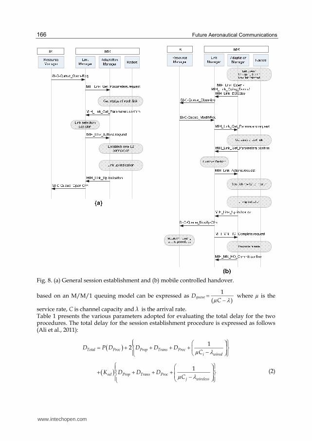
The message sequence charts in Fig. 8 demonstrate how MIH primitives can incorporate
BSM SI-SAP primitives for general session establishment (link selection by LM) and mobile
controlled handover. The BSM SI-SAP primitives are shown as the signalling messages
carried over the interface between the IR and IMR. These SI-SAP primitives will trigger a
sequence of MIH link independent primitives, which will further trigger the link dependent
primitives.
As seen in Fig. 8 (a), the resource request in a new session establishment procedure is
handled by the ETSI BSM SI-C-Queue_Open-Req primitive that demands specific QoS
requirements to be fulfilled by the IMR link setting. Upon reception of this primitive, the
IMR makes use of MIH primitives to check the link status of each available radio technology
then perform the link selection function to establish L2 connection on the selected radio
technology. Finally, the ESTI BSM SI-C-Queue_Open-Cfm primitive is used by the IMR to
confirm the establishment of L2 connection with the IR.
Fig. 8 (b) presents the layer 2 connection establishment procedure for handover using the
ETSI BSM SI-C-Queue_Modify-Req primitive that indicates a new queue modify request
due to the unavailability of resources on a given link or the detection of a newly available
link that triggers a handover event. Consequently, QoS re-negotiation is required on the
new link. This phase is then accomplished by making use of both ETSI BSM and MIH
primitives as can be seen from the first three signalling message exchanges between the IR
and the IMR.
4.6 Performance analysis of RRM procedures To evaluate the performance of the RRM procedures, time delay analysis has been carried out based on the message sequence charts. The various wired and wireless links and interfaces between different network components shown in Fig. 8 have been considered. All messages involved in the procedure like connection establishment and handover have been taken into account in calculating the different delay components. In general, the total time taken to transmit a single message over any given link, DTotal can be expressed as the sum of four delay components (Pillai & Hu, 2009):
Total Prop Proc Trans queueD D D D D (1)
Where, DProp is the propagation delay, DProc is the processing delay, Dqueue is queuing delay and DTrans is the transmission delay. The general queuing delay Dqueue for any network entity,
www.intechopen.com
Future Aeronautical Communications
166
Fig. 8. (a) General session establishment and (b) mobile controlled handover.
based on an M/M/1 queuing model can be expressed as Dqueue1
( ) µC where µ is the
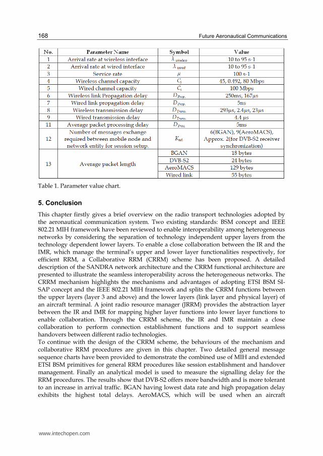
service rate, C is channel capacity and λ is the arrival rate. Table 1 presents the various parameters adopted for evaluating the total delay for the two procedures. The total delay for the session establishment procedure is expressed as follows (Ali et al., 2011):
12Total Proc Prop Trans Proc
i wired
D P D D D DµC
1sel Prop Trans Proc
j wireless
K D D DµC
(2)
www.intechopen.com
Interoperability Among Heterogeneous Networks for Future Aeronautical Communications
167
In Equation 2, P represents the total number of messages exchanged between entities within the IMR where Ksel denotes the number of messages required for session establishment over the selected wireless link. Ci and Cj denote the capacity of wired and wireless communication channel. Similarly, the signalling delay for the handover procedure shown in Fig. 8 (b) is given by equation (3), where Q represents the total number of messages exchanged within IMR entities.
13Total Proc Prop Proc Trans
i wired
D Q D D D DµC
1 –
Sel Prop Trans Procj wireless
K D D DµC
(3)
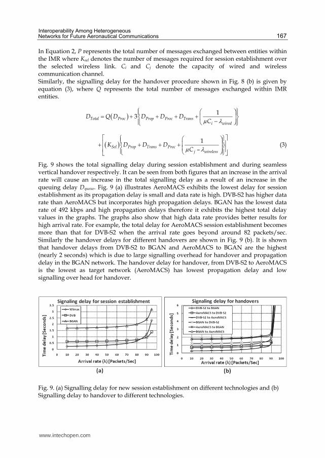
Fig. 9 shows the total signalling delay during session establishment and during seamless vertical handover respectively. It can be seen from both figures that an increase in the arrival rate will cause an increase in the total signalling delay as a result of an increase in the queuing delay Dqueue. Fig. 9 (a) illustrates AeroMACS exhibits the lowest delay for session establishment as its propagation delay is small and data rate is high. DVB-S2 has higher data rate than AeroMACS but incorporates high propagation delays. BGAN has the lowest data rate of 492 kbps and high propagation delays therefore it exhibits the highest total delay values in the graphs. The graphs also show that high data rate provides better results for high arrival rate. For example, the total delay for AeroMACS session establishment becomes more than that for DVB-S2 when the arrival rate goes beyond around 82 packets/sec. Similarly the handover delays for different handovers are shown in Fig. 9 (b). It is shown that handover delays from DVB-S2 to BGAN and AeroMACS to BGAN are the highest (nearly 2 seconds) which is due to large signalling overhead for handover and propagation delay in the BGAN network. The handover delay for handover, from DVB-S2 to AeroMACS is the lowest as target network (AeroMACS) has lowest propagation delay and low signalling over head for handover.
Fig. 9. (a) Signalling delay for new session establishment on different technologies and (b) Signalling delay to handover to different technologies.
www.intechopen.com
Future Aeronautical Communications
168
Table 1. Parameter value chart.
5. Conclusion
This chapter firstly gives a brief overview on the radio transport technologies adopted by the aeronautical communication system. Two existing standards: BSM concept and IEEE 802.21 MIH framework have been reviewed to enable interoperability among heterogeneous networks by considering the separation of technology independent upper layers from the technology dependent lower layers. To enable a close collaboration between the IR and the IMR, which manage the terminal’s upper and lower layer functionalities respectively, for efficient RRM, a Collaborative RRM (CRRM) scheme has been proposed. A detailed description of the SANDRA network architecture and the CRRM functional architecture are presented to illustrate the seamless interoperability across the heterogeneous networks. The CRRM mechanism highlights the mechanisms and advantages of adopting ETSI BSM SI-SAP concept and the IEEE 802.21 MIH framework and splits the CRRM functions between the upper layers (layer 3 and above) and the lower layers (link layer and physical layer) of an aircraft terminal. A joint radio resource manager (JRRM) provides the abstraction layer between the IR and IMR for mapping higher layer functions into lower layer functions to enable collaboration. Through the CRRM scheme, the IR and IMR maintain a close collaboration to perform connection establishment functions and to support seamless handovers between different radio technologies. To continue with the design of the CRRM scheme, the behaviours of the mechanism and collaborative RRM procedures are given in this chapter. Two detailed general message sequence charts have been provided to demonstrate the combined use of MIH and extended ETSI BSM primitives for general RRM procedures like session establishment and handover management. Finally an analytical model is used to measure the signalling delay for the RRM procedures. The results show that DVB-S2 offers more bandwidth and is more tolerant to an increase in arrival traffic. BGAN having lowest data rate and high propagation delay exhibits the highest total delays. AeroMACS, which will be used when an aircraft
www.intechopen.com
Interoperability Among Heterogeneous Networks for Future Aeronautical Communications
169
approaches the airport, having low propagation delay and high data rate, shows the lowest total delay. Since DVB-S2 has the same propagation delay as BGAN but with a higher data rate, its delay performance is better than AeroMACS under high arrival rate.
6. Acknowledgment
The research leading to these results has been partially funded by the European
Community's Seventh Framework Programme (FP7/2007-2013) under Grant Agreement n°
233679. The SANDRA project is a Large Scale Integrating Project for the FP7 Topic
AAT.2008.4.4.2 (Integrated approach to network centric aircraft communications for global
aircraft operations). The project has 31 partners and started on 1st October 2009.
7. References
Ali, M., Xu, K., Pillai, P., &Hu, Y.F. (2011). Common RRM in Satellite-Terrestrial
Based Aeronautical Communication Networks, PSATS 2011, Spain, February
2011.
ARINC. (2011). Aircraft Communications Addressing and Reporting System (ACARS),
Available from http://www.arinc.com/products/voice_data_comm/acars.html.
Denos, R. (2010). Aeronautics and Air Transport Research - 7th Framework Programme 2007-2013
- Project Synopses, Volume 1 Calls 2007 & 2008, European Commission.
Devarapalli, V., Wakikawa, R., Petrescu, A., & Thubert, P. (2005). Network Mobility (NEMO)
Basic Support Protocol. RFC 3963.
ESA. (2003). BGAN Project Objectives, Available from
http://telecom.esa.int/telecom/www/object/index.cfm?fobjectid=11366
ETSI. (2005). Technical Specification, Satellite Earth Stations and Systems (SES); Broadband
Satellite Multimedia (BSM) Common air interface specification; Satellite Independent
Service Access Point (SI-SAP).TS 102 357 V1.1.1.
ETSI. (2007).Technical Report, Satellite Earth Station and Systems (SES); Broadband Satellite
Multimedia (BSM); Services and architectures.TR 101 984 V1.2.1.
ETSI. (2009a).Technical Report, Reconfigurable Radio System (RRS); Software Defined Radio
Reference Architecture for Mobile Device. TR 102 680 V1.1.1.
ETSI. (2009b).Digital Video broadcasting (DVB) 2nd generation framing structure, channel coding
& modulation systems for broadcasting, interactive services, news gathering and other
broadband satellite applications (DVB-S2).EN 302 307 V1.2.1.
ETSI. (2009c). Technical Report, Reconfigurable Radio System (RRS); Radio Base Station (RBS)
Software Defined Radio (SDR) status, implementations and costs aspects, including future
possibilities. TR 102 681 V1.1.1.
EUROCONTROL. (2001). FAA/EUROCONTROL Memorandum of Co-operation, Available
from http://www.eurocontrol.int/moc-faa-
euro/public/subsite_homepage/homepage.html
EUROCONTROL. (2006). Long-Term Forecast, Flight Movements (2006 - 2025) v1.0,
EUROCONTROL.
EUROCONTROL/FAA. (2007). Action Plan 17: Final Conclusions and Recommendations Report,
EUROCONTROL/FAA Memorandum of Cooperation.
www.intechopen.com
Future Aeronautical Communications
170
EUROCONTROL. (2009). IEEE 802.16e System Profile Analysis for FCI’s Airport Surface
Operation, EUROPEAN AIR TRAFFIC MANAGEMENT
Fantacci, R., Marabissi, D., & Tarchi, D. (2009). Adaptive Scheduling Algorithms for
Multimedia Traffic in Wireless OFDMA Systems. Physical Communication, vol. 2, pp.
228-234.
Giambene, G. (2007).Resource Management in Satellite Networks: Optimization and Cross-Layer
Design, 1st ed, Springer.
Homans, A. (2002). The Evolving Role of the Communication Service Provider. Integrated
CNS Technologies Conference and Workshop, May 2002.
ICAO .(2001). Manual on VHF Digital Link (VDL) Mode 2, Doc 9776 AN/970.
IEEE. (2009a). Part 16: Air Interface for Broadband Wireless Access Systems. IEEE Std. 802.16.
IEEE. (2009b). Local and Metropolitan Area Networks - Media Independent Handover Services.
IEEE Std. 802.21.
INMARSAT. (2003). INMARSAT BGAN System Definition Manual.
INMARSAT. (2011). BGAN, Available from http://www.inmarsat.com
/Services/Land/Services/High_speed_data/default.aspx
Jilg, G. (2002). INMARSAT - products and strategies, Workshop on Satellites in IP and
Multimedia, Geneva.
Kumar, G. S. A., Manimaran, G., & Wang, Z. (2009). Energy-Aware Scheduling with
Probabilistic Deadline Constraints in Wireless Networks. Ad Hoc Networks, vol. 7,
pp. 1400-1413.
Kuroda, M., Saito, Y., Ishizu, K., & Komiya, R. (2006). Clarification of MIH_NMS_SAP, DCN:
21-06-0786-00-0000.
NASA. (2005). Technology assessment for the future aeronautical communications systems, NASA
ITT Industries, NASA-CR-20050213587
Pillai, P., & Hu, Y. F. (2009). Performance analysis of EAP methods used as GDOI Phase 1
for IP multicast on Airplanes, WAINA'09 international Conference, June 2009.
SANDRA. (2011). SANDRA Concept, Available from http://www.sandra.aero
www.intechopen.com
Future Aeronautical CommunicationsEdited by Dr. Simon Plass
ISBN 978-953-307-625-6Hard cover, 378 pagesPublisher InTechPublished online 26, September, 2011Published in print edition September, 2011
InTech EuropeUniversity Campus STeP Ri Slavka Krautzeka 83/A 51000 Rijeka, Croatia Phone: +385 (51) 770 447 Fax: +385 (51) 686 166www.intechopen.com
InTech ChinaUnit 405, Office Block, Hotel Equatorial Shanghai No.65, Yan An Road (West), Shanghai, 200040, China
Phone: +86-21-62489820 Fax: +86-21-62489821
There are well-founded concerns that current air transportation systems will not be able to cope with theirexpected growth. Current processes, procedures and technologies in aeronautical communications do notprovide the flexibility needed to meet the growing demands. Aeronautical communications is seen as a majorbottleneck stressing capacity limits in air transportation. Ongoing research projects are developing thefundamental methods, concepts and technologies for future aeronautical communications that are required toenable higher capacities in air transportation. The aim of this book is to edit the ensemble of newestcontributions and research results in the field of future aeronautical communications. The book gives thereaders the opportunity to deepen and broaden their knowledge of this field. Today’s and tomorrow’sproblems / methods in the field of aeronautical communications are treated: current trends are identified; IPv6aeronautical network aspect are covered; challenges for the satellite component are illustrated; AeroMACSand LDACS as future data links are investigated and visions for aeronautical communications are formulated.
How to referenceIn order to correctly reference this scholarly work, feel free to copy and paste the following:
Kai Xu, Prashant Pillai, Yim Fun Hu and Muhammad Ali (2011). Interoperability Among HeterogeneousNetworks for Future Aeronautical Communications, Future Aeronautical Communications, Dr. Simon Plass(Ed.), ISBN: 978-953-307-625-6, InTech, Available from: http://www.intechopen.com/books/future-aeronautical-communications/interoperability-among-heterogeneous-networks-for-future-aeronautical-communications

© 2011 The Author(s). Licensee IntechOpen. This chapter is distributedunder the terms of the Creative Commons Attribution-NonCommercial-ShareAlike-3.0 License, which permits use, distribution and reproduction fornon-commercial purposes, provided the original is properly cited andderivative works building on this content are distributed under the samelicense.


![Domain knowledge Interoperability to build the Semantic ... · – Lack of semantic web best practices [OneM2M, Gyrard 2014] – Heterogeneous terms used (e.g., etymology, synonyms)](https://img.pdfslide.net/doc/110x75/5f14f089034c873af648ceaf/domain-knowledge-interoperability-to-build-the-semantic-a-lack-of-semantic.jpg)