Embed Size (px)
Citation preview

European Network of Transmission System Operators
for Electricity IOP “CIM FOR SYSTEM DEVELOPMENT AND OPERATIONS” 2012
ENTSO-E AISBL • Avenue Cortenbergh 100 • 1000 Brussels • Belgium • Tel +32 2 741 09 50 • Fax +32 2 741 09 51 • [email protected] • www.entsoe.euENTSO-E AISBL • Avenue Cortenbergh 100 • 1000 Brussels • Belgium • Tel +32 2 741 09 50 • Fax +32 2 741 09 51 • [email protected] • www.entsoe.eu
INTEROPERABILITY TEST “CIM FOR SYSTEM DEVELOPMENT
AND OPERATIONS” 2012
3 SEPTEMBER 2012
FINAL REPORT
European Network of Transmission System Operators
for Electricity
Page 2 of 24
ENTSO-E AISBL • Avenue Cortenbergh 100 • 1000 Brussels • Belgium • Tel +32 2 741 09 50 • Fax +32 2 741 09 51 • [email protected] • www.entsoe.eu
IOP “CIM FOR SYSTEM DEVELOPMENT AND OPERATIONS” 2012
European Network of Transmission System Operators
for Electricity
FOREWORD
ENTSO-E conducted, along with European and American vendors and Transmission System Operators (TSOs), a common information model (CIM) interoperability test (IOP) – ENTSO-E IOP “CIM for System Development and Operations” 2012. The test was organized and directed by ENTSO-E from 9 to 13 July 2012 at ENTSO-E’s premises, in Brussels.
The future ENTSO-E CIM-based data exchange format (ENTSO-E CIM profile) for grid models exchange, which complies with the International Electrotechnical Commission (IEC) CIM standards 61970 (parts 301, 452, 453, 456, 552), was tested on a large number of products. Alstom grid, BCP Busarello + Cott + Partner AG, CESI, DIgSILENT, DMS Group and EKC, FGH, Intercompro AG, Mikronika, Open Grid Systems, RTE, SISCO, Tractebel, Ventyx/ABB and Grid Cloud Systems participated in the testing.
The test on exchange of power system models is carried out as a part of the ENTSO-E CIM profile development process. Key goals were to test and validate the latest IEC draft CIM standards on which the new 2nd edition of the ENTSO-E CIM Profile is based on as well as the correct implementation of the 1st edition of the ENTSO-E CIM Profile which is currently used for some of the ENTSO-E data exchanges. The implementation schedule for the ENTSO-E CIM profile that was tested is subject to ENTSO-E decision, as defined by the ENTSO-E roadmap for implementation of future updates of the data exchange format as previously announced.
The recently developed ENTSO-E Network Modelling Database (NMD) was involved in the tests in order to improve the interoperability of CIM-based data exchanges between TSOs and the NMD platform. All TSOs were involved in tests related to NMD. The NMD was developed to improve TSOs’ coordinated planning of the European transmission grid. Overall, the NMD will contribute to higher security of supply, secure integration of renewable resources, and a reliable future-oriented grid.
During the preparatory stage an additional rule set was agreed which is to be applied to the 1st edition of the ENTSO-E CIM Profile. These additional rules are mandatory and modify some of the specifications of the 1st edition of the ENTSO-E CIM Profile.
A set of test procedures were defined which provided step-by-step instructions to be followed to successfully complete each test. A set of official test cases were prepared by CESI, Ventyx/ABB, Open Grid Systems, FGH, DIgSILENT, BCP Busarello + Cott + Partner AG, Mikronika and ENTSO-E for use by all test participants.
Two CIM XML validation tools (CIMSpy and CIMdesk) were used to validate the correctness of the official test cases as well as each set of CIM XML files produced by the participants during the test.
The second edition of the ENTSO-E CIM Profile was created using the tool - CimConteXtor.
Page 3 of 24
ENTSO-E AISBL • Avenue Cortenbergh 100 • 1000 Brussels • Belgium • Tel +32 2 741 09 50 • Fax +32 2 741 09 51 • [email protected] • www.entsoe.eu
IOP “CIM FOR SYSTEM DEVELOPMENT AND OPERATIONS” 2012
European Network of Transmission System Operators
for Electricity
The results achieved during the test are in line with the expectations of the participants. The test results are summarized and presented in detail in this report showing the specific tests successfully completed by each vendor and the test case files that were exchanged.
Issues recorded during the testing and proposed resolutions are included in this report, along with some guidelines on how to implement the CIM standards within the TSO/utility enterprise. Details on the products tested and the test procedures are included in the report appendices.
The report is agreed by the IOP participants and it is a basis for further discussions in the ENTSO-E Committees as well as in IEC TC57/WG13.
Page 4 of 24
ENTSO-E AISBL • Avenue Cortenbergh 100 • 1000 Brussels • Belgium • Tel +32 2 741 09 50 • Fax +32 2 741 09 51 • [email protected] • www.entsoe.eu
IOP “CIM FOR SYSTEM DEVELOPMENT AND OPERATIONS” 2012
European Network of Transmission System Operators
for Electricity
ACKNOWLEDGEMENTS
ENTSO-E would like to thank the many people who worked hard to make the ENTSO-E Interoperability Test “CIM for System Development and Operations” 2012 a success. Not all people who contributed can be named here. However, ENTSO-E would like to give special recognition to the following utilities and vendors:
• ENTSO-E – Chavdar Ivanov, Jesus Mendiola and Adam Szekely for directing the IOP, for assistance in witnessing the IOP, for preparation of test procedures, ENTSO-E CIM Profile document, the official test files and the final report.
• All participating TSOs as test witnesses for profile 2 or involved in testing profile 1 and ENTSO-E Network Modelling Database.
• Alstom Grid - Jean-Francois Rouch, Alexandre Petrenco, Silverio Casulli and other team members for supporting the tests on the ENTSO-E Network Modelling Database.
• Unicorn - Karel Schejbal, Vlastimil Unucka, Jiří Dudek and other team members for supporting the tests on the ENTSO-E Network Modelling Database.
• DIgSILENT – Christoph Schmid for supporting preparation of official test files for testing IEC 60909.
• Open Grid Systems - Alan McMorran for supporting preparation of the official test files.
• BCP Busarello + Cott + Partner AG - Giatgen Cott for supporting preparation of the official test files in the part covering IEC 60909.
• FGH - Dirk Cremer for preparation of official test files for testing IEC 60909.
• CESI - Dario Frazzetta for supporting preparation of official test files.
• Ventyx/ABB - Lars-Ola Osterlund for supporting preparation of official test files.
• Mikronika - Michał Wiernowolski for supporting preparation of official test files.
• PowerInfo - Jun Zhu for generation of CIMSpy and CIMdesk validation tools used to validate the model files for his assistance in preparation of the profile.
• Jean-Luc Sanson (ITG) and Andre Maizener (Zamiren) for maintaining CimConteXtor, which was used to generate the new draft of the 2nd edition of the ENTSO-E CIM profile.
• All participating vendors, for the hard work in a very short time to develop the necessary software for testing and providing inputs to the issues discussed during the preparatory work as well as during the IOP.
In addition, ENTSO-E acknowledges IEC TC57/WG13 members and CIM user group that provided assistance and supported ENTSO-E IOP in various ways.
Page 5 of 24
ENTSO-E AISBL • Avenue Cortenbergh 100 • 1000 Brussels • Belgium • Tel +32 2 741 09 50 • Fax +32 2 741 09 51 • [email protected] • www.entsoe.eu
IOP “CIM FOR SYSTEM DEVELOPMENT AND OPERATIONS” 2012
European Network of Transmission System Operators
for Electricity
Contents
1 INTRODUCTION .......................................................................................................... 6
1.1 BACKGROUND INFORMATION ............................................................................................................ 6 1.2 OBJECTIVES ................................................................................................................................... 8
2 SUMMARY OF TEST RESULTS ..................................................................................... 9
3 SUMMARY OF IDENTIFIED ISSUES ............................................................................. 11
3.1 ISSUES ADDRESSED TO IEC ........................................................................................................... 12 3.1.1 ISSUE IEC 1: CURVE CLASS - MISSING ATTRIBUTES ......................................................................... 12 3.1.2 ISSUE IEC 2: SYNCHRONOUSMACHINE CLASS - OUTDATED ATTRIBUTES ............................................ 12 3.1.3 ISSUE IEC 3: EXTERNALNETWORKINJECTION.GOVERNORSCD ........................................................ 12 3.1.4 ISSUE IEC 4: SYNCHRONOUSMACHINE.SATDIRECTTRANSX ............................................................ 12 3.1.5 ISSUE IEC 5: EXTERNALNETWORKINJECTION.MAXP ........................................................................ 13 3.1.6 ISSUE IEC 6: EXTERNALNETWORKINJECTION.MINP ......................................................................... 13 3.1.7 ISSUE IEC 7: SYNCHRONOUSMACHINE.SHORTCIRCUITROTORTYPE ................................................. 13 3.1.8 ISSUE IEC 8: TRANSFORMER MODEL .............................................................................................. 13 3.1.9 ISSUE IEC 9: NAME, NAMETYPE ISSUE. .......................................................................................... 13 3.1.10 ISSUE IEC 10: CLARIFICATION REGARDING RDF:ID AND MRID .......................................................... 14 3.1.11 ISSUE IEC 11: SHUNTCOMPENSATOR ............................................................................................ 14 3.1.12 ISSUE IEC 12: ROUNDING ISSUE - DIFFERENCE FILES ...................................................................... 14 3.1.13 ISSUE IEC 13: USE OF BAY CLASS ................................................................................................. 14 3.1.14 ISSUE IEC 14: CONNECTIVITYNODE IN LINE .................................................................................... 15 3.1.15 ISSUE IEC 15: DIFFERENT DEVICES ON THE SAME REGULATING CONTROL ......................................... 15 3.1.16 ISSUE IEC 16: GENERATINGUNIT, FUEL TYPES ISSUE ...................................................................... 15 3.1.17 ISSUE IEC 17: ISSUES FROM IOP2011 .......................................................................................... 15 3.1.18 ISSUE IEC 18: ISSUES AGREED BEFORE IOP .................................................................................. 16 3.1.19 ISSUE IEC 19: POTENTIAL CHANGES ON ROTATINGMACHINE ........................................................... 16 3.2 PROFILE 1 (BASED ON UML14V02) ISSUES..................................................................................... 16 3.3 PROFILE 2 (BASED ON UML16V10) ISSUES..................................................................................... 17 3.3.1 ISSUE ENTSO-E 1: VSCCAPABILITYCURVE CLASS INHERITED ATTRIBUTES ...................................... 17 3.3.2 ISSUE ENTSO-E 2: SYNCHRONOUSMACHINE R AND X .................................................................... 18 3.3.3 ISSUE ENTSO-E 3: MISSING ATTRIBUTES NEEDED FOR DYNAMICS PROFILE ..................................... 18 3.3.4 ISSUE ENTSO-E 4: SHORTCIRCUIT CLASSES AND ATTRIBUTES ........................................................ 18 3.3.5 ISSUE ENTSO-E 5: DIAGRAM LAYOUT: VISIBILITYLAYER ................................................................. 19 3.3.6 ISSUE ENTSO-E 6: DIAGRAM LAYOUT: DIAGRAMOBJECTSTYLE ...................................................... 19
4 CONCLUSIONS AND RECOMMENDATIONS .................................................................. 19
5 REFERENCES .......................................................................................................... 23
6 APPENDIX A: INFORMATION ON TOOLS TESTED/USED IN THE IOP .............................. 24
7 APPENDIX B: TEST PROCEDURES ............................................................................ 24
8 APPENDIX C: TEST RECORD FORMS ......................................................................... 24

Page 6 of 24
ENTSO-E AISBL • Avenue Cortenbergh 100 • 1000 Brussels • Belgium • Tel +32 2 741 09 50 • Fax +32 2 741 09 51 • [email protected] • www.entsoe.eu
IOP “CIM FOR SYSTEM DEVELOPMENT AND OPERATIONS” 2012
European Network of Transmission System Operators
for Electricity
1 INTRODUCTION
1.1 BACKGROUND INFORMATION
In 2009 the ENTSO-E member TSOs have been underlining their commitment to apply the CIM-based data exchange format in all data exchange processes. This format is based on the CIM standards of the International Electrotechnical Commission and was initially tested during the UCTE interoperability test in March 2009. Using CIM will improve TSO cooperation and will have a direct impact on the outputs, the Third Energy Package of the EU mandates ENTSO-E to produce. For the first time the CIM-based exchange format is used in early 2010 for preparing network models as a basis for system development studies. One important example in this context is the Ten-Year Network Development Plan, which will benefit from the upcoming CIM-based data exchanges for network modelling. In addition to applying the CIM-based data exchange format for the exchange of system studies, the exchange of system operations data (performed on an hourly or daily basis) will be adjusted to the use the CIM-based data exchange format. The support from vendors is essential in this context since they are providing software tools required for the effective use of the CIM-based data exchange format.
On 11 December 2009 ENTSO-E decided to organize two Common Information Model (CIM) interoperability tests per year to support the development of the ENTSO-E CIM-based data exchange format and the CIM Standard issued by the International Electrotechnical Commission (IEC). Moreover, ENTSO-E agreed on a roadmap for the implementation of future updates of the CIM-based format for exchanges of system operations and system studies. The purpose of these tests is to demonstrate the interoperability of the ENTSO-E CIM-based data exchange format and the IEC CIM-based standard taking into account all changes proposed to be included in the updated CIM standard. The tests are also designed in order to allow vendors to verify the correctness of the implementation of the updated CIM standard and to support ENTSO-E processes towards achieving the objectives given to ENTSO-E by the EU Third Energy Package. More specifically, the Regulation 714/2009 on conditions for access to the network for cross-border exchanges in electricity states that ENTSO-E has to adopt common network operation tools to ensure the coordination of network operation, to elaborate network codes on data exchange and interoperability rules as well as transparency rules.
The adoption of the ENTSO-E CIM interoperability tests and the CIM/XML-based data exchange format is a direct contribution to the above mentioned tasks since it supports data exchanges and ensures the interoperability of the tools used in the ENTSO-E data exchange processes. The experience gained from the process of developing CIM-based data exchange format and its implementation will directly contribute to the task to develop network codes required by the Third Energy Package by the European Union. The interaction is obvious taking into account the fact that data exchange processes and formats used in these processes will be part of several network codes.
In 2009, ENTSO-E agreed to organize up to two CIM Interoperability tests per year:

Page 7 of 24
ENTSO-E AISBL • Avenue Cortenbergh 100 • 1000 Brussels • Belgium • Tel +32 2 741 09 50 • Fax +32 2 741 09 51 • [email protected] • www.entsoe.eu
IOP “CIM FOR SYSTEM DEVELOPMENT AND OPERATIONS” 2012
European Network of Transmission System Operators
for Electricity
• The ENTSO-E IOP "CIM for System Development and Operations" that covers all needs of system development and operations such as operational to operational exchanges, operational to planning, short circuit data, planning, dynamics exchanges and the interface with distribution. Specific data collection and data processes can also be tested. The goal is to allow and facilitate any kind of study in TSOs' scope: static analyses, dynamic studies, short circuit assessments, etc.;
• The ENTSO-E IOP "CIM for Energy Market" that covers needs of market exchanges. It contributes to the further development of the IEM (European Internal Energy Market) by actively supporting market harmonization and integration and plays a crucial role for demonstrating the correctness of European market CIM profile.
Additional information on CIM activities in ENTSO-E is available here.
This document reports the results of the ENTSO-E Interoperability Test „CIM for System Development and Operations“ 2012.
The chart below illustrates the versions of the ENTSO-E profile and the IOPs performed since 2009. In order to have short reference in this document:
- profile 1 - refers to 1st edition of the profile publishes in May 2009 (UML14v02) and which includes all annexes agreed since 2009. The version is available here.
- profile 2 is the last version (version 2.3) of the 2nd edition of the ENTSO-E profile - currently based on UML16v10. The version is available here.
ENTSO-E CIM Profiles
Profile 1 (CIM14, UML14v02) Profile 2 IEC CIM development ENTSO-E decisions Comments
20
09
20
10
20
11
20
12
20
08 CIM 13
Draft version 1.01st Edition ENTSO-E profile – IOP
March 2009 (UML 14v02)
Final version 1.11st Edition ENTSO-E profile – May
2009 (UML 14v02)
Primarily designed for a bus-branch model representationDoes not include file header informationModel assembling (merging) requires more logic when implementingPure load flow exchange (no dynamics, no graphics, no GIS, limited short circuit data exchange)
CIM 14Draft version(UML 14v02)
CIM 14Draft version (UML 14v15)
CIM 14Official release (UML 14v15)
Draft version 2.12nd Edition ENTSO-E profile,
UML 14v15
Annex issued to the final version 1.1
1st Edition ENTSO-E profile –July 2011 (UML 14v02)
Draft version 2.22nd Edition ENTSO-E profile, UML 15v31 – IOP July 2011
CIM 15Draft version (UML 15v31)
File header Draft of dynamics partNew transformer & PST modelExchange of Diagram layout Exchange of Geographical locationShort circuit data exchange is adapted to IEC 60909
CIM 15Official release (UML 15v33)
CIM 16Draft version (UML 16v10)
In addition to version 2.2, version 2.3 contains:ENTSO-E CIM extensions for short circuit added to CIM16 Updated draft of dynamics part, but not part of IOP 2012Draft HVDC model, but not part of IOP 2012
Annex issued to the final version 1.1
1st Edition ENTSO-E profile –July 2012 (UML 14v02)
Draft version 2.32nd Edition ENTSO-E profile, UML 16v10 – IOP July 2012
Based on
Based on
Based on
Based on
Do not implement version 2.1 of the 2nd edition of the ENTSO-E CIM profile. Continue with v1.1 –
1st edition (UML 14v02)
Implement version 1.1 – 1st edition of the ENTSO-E CIM
profile (UML14v02)
Do not implement version 2.2 of the 2nd edition of the ENTSO-E CIM profile. Continue with v1.1 (annex included) – 1st edition
(UML 14v02)
Page 8 of 24
ENTSO-E AISBL • Avenue Cortenbergh 100 • 1000 Brussels • Belgium • Tel +32 2 741 09 50 • Fax +32 2 741 09 51 • [email protected] • www.entsoe.eu
IOP “CIM FOR SYSTEM DEVELOPMENT AND OPERATIONS” 2012
European Network of Transmission System Operators
for Electricity
1.2 OBJECTIVES
The IEC is publishing international standards based on the CIM as a generalized abstract information model and is progressing data interface specifications based on the CIM to exchange power system models. The ENTSO-E CIM IOP is an important step in validating these standards as well as the new draft of the 2nd edition of the ENTSO-E CIM Profile which specifies those parts of the CIM needed to support the ENTSO-E business processes.
ENTSO-E IOP is a stage in the development process of the next ENTSO-E CIM based data exchange format, which will become official data exchange format once endorsed by the ENTSO-E committees responsible for these data exchanges. The IOP helps to verify CIM profile definitions and debug vendors’ tools in order to ensure smooth implementation process once ENTSO-E decision is taken.
The general objectives of the ENTSO-E interoperability tests and demonstrations were to:
1. Demonstrate interoperability between different products based on the ENTSO-E CIM Model Exchange Profile (here after referred to as the ENTSO-E CIM profile). This included applications from EMS and Planning as well as independently developed applications from third party suppliers.
2. Validate the ENTSO-E CIM Profile document. The goal was to ensure it is correct, complete and ready to be used in ENTSO-E data exchanges or identify issues to be further corrected and verified during the next ENTSO-E IOP.
3. Demonstrate the exchange of power system models using the CIM with an RDF Schema and XML representation of the model data.
4. Demonstrate that the test participants’ applications work effectively with the CIM XML files by performing and comparing power flows in the test models.
5. Demonstrate that the application vendors can interoperate via the ENTSO-E CIM profile by showing that CIM cases produced by one vendor can be consumed and utilized by the others.
Specific objectives of the ENTSO-E IOP 2012 included validation of the:
• Testing of the ENTSO-E Network Modelling Database to simulate exchange of real TSOs models exported for profile 1 (CIM14, UML14v02) including real performance tests of such exchanges.
• Validate the new version of the 2nd edition of the ENTSO-E CIM profile based on CIM16 (UML16v10). The following main features of CIM16 were covered in the tests:
o File header;
o Model Authority Sets;
Page 9 of 24
ENTSO-E AISBL • Avenue Cortenbergh 100 • 1000 Brussels • Belgium • Tel +32 2 741 09 50 • Fax +32 2 741 09 51 • [email protected] • www.entsoe.eu
IOP “CIM FOR SYSTEM DEVELOPMENT AND OPERATIONS” 2012
European Network of Transmission System Operators
for Electricity
o Model assembling process: assembling of models submitted by different model authority sets;
o Verification of the ENTSO-E extensions for short circuit according to IEC 60909 which were included in CIM16 by IEC WG13;
o Exchange of data for short circuit calculations according to IEC 60909;
o Exchange of diagram layout - IEC 61970-453;
o Exchange of GIS data;
o Exchange between SCADA/EMS and „planning“ tools;
o Partial exchange of CIM profiles (equipment, topology, state variables, etc);
o Exchange of difference files.
2 SUMMARY OF TEST RESULTS Test procedures defined for the ENTSO-E Interoperability test described 33 tests that cover all necessary functionalities to be applied in the ENTSO-E data exchanges for the 2nd profile and additional 8 tests related to the tests performed for profile 1 (UML14v02). Due to the large number of tests and tools that were tested during the IOP not all predefined tests could be performed by all vendors and using all official test models and the two editions of the ENTSO-E CIM Profiles. In addition, some of the tools that were tested do not support some of the data exchanges.
In order to check the new draft version of the 2nd edition of the ENTSO-E CIM profile in an efficient way, vendors focussed on different parts of the profile. No scores were applied for testing of profile 2 as all tests are considered as part of profile development process.
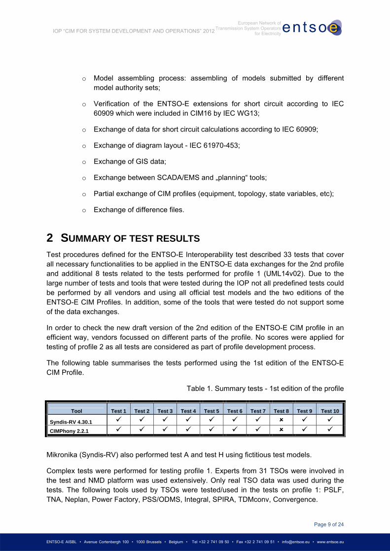
The following table summarises the tests performed using the 1st edition of the ENTSO-E CIM Profile.
Table 1. Summary tests - 1st edition of the profile
Tool Test 1 Test 2 Test 3 Test 4 Test 5 Test 6 Test 7 Test 8 Test 9 Test 10
Syndis-RV 4.30.1
CIMPhony 2.2.1
Mikronika (Syndis-RV) also performed test A and test H using fictitious test models.
Complex tests were performed for testing profile 1. Experts from 31 TSOs were involved in the test and NMD platform was used extensively. Only real TSO data was used during the tests. The following tools used by TSOs were tested/used in the tests on profile 1: PSLF, TNA, Neplan, Power Factory, PSS/ODMS, Integral, SPIRA, TDMconv, Convergence.
Page 10 of 24
ENTSO-E AISBL • Avenue Cortenbergh 100 • 1000 Brussels • Belgium • Tel +32 2 741 09 50 • Fax +32 2 741 09 51 • [email protected] • www.entsoe.eu
IOP “CIM FOR SYSTEM DEVELOPMENT AND OPERATIONS” 2012
European Network of Transmission System Operators
for Electricity
The tests on profile 1 using real models and NMD could be summarized as follows:
Business related issues and data inconsistencies delayed the process, but most of these issues were resolved during the IOP week.
Due to various automatic validation procedures in the NMD the data consistency and quality of the models were significantly improved. Nevertheless various issues in NMD were found and reported to the NMD vendors. Some of the issue were fixed during the IOP week, but other will be resolved as soon as possible. The system should have better characteristics in terms of performance and react adequately with minimal set of "unexpected" errors.
Most of TSOs still observe non compliance of their tools with definitions of profile 1. Some of the issues observed during the IOP were fixed by vendors. TSOs will report the rest of the issues to vendors and require correction of their tools. The following tools related issues were reported by TSOs in their test reports:
o PSS/ODMS: issue related to TransformerWinding - values present in the model but not exported in the equipment part of the profile.
o PSS/ODMS: exchange between PSS/E and PSS/ODMS is not 1:1. Load flow should be the same in both directions. Data in PSS/ODMS should be available in PSS/E, i.e. fuel types, substation names, etc.
o Neplan: Properties PhaseTapChangerAsymetrical.windingConnectionAngle, PhaseTapChangerNonLinear.voltageStepIncrement, TapChanger.normalStep, Switch.normalOpen, Switch.retained should not ne exported for profile 1.
o PSLF: Upon re-import of exported CIM data it is observed that transformation ratio PSLF type 1 transformers is changes in comparison with the original data. Investigated and reported to vendor.
o PLSF: Few issues observed when assembling multiple CIM models. The loads at coupled x-nodes are not switched off. Reported to vendor.
o PSLF: Issues found with mapping PSLF zones to SubGeorgraphicalRegion and vice-verse. Reported to vendor.
o PSLF: ENTSO-E naming convention not fully supported when importing CIM data.
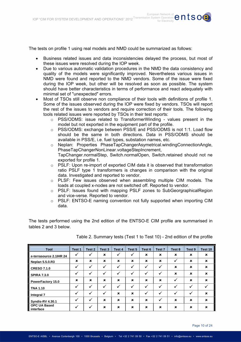
The tests performed using the 2nd edition of the ENTSO-E CIM profile are summarised in tables 2 and 3 below.
Table 2. Summary tests (Test 1 to Test 10) - 2nd edition of the profile
Tool Test 1 Test 2 Test 3 Test 4 Test 5 Test 6 Test 7 Test 8 Test 9 Test 10
e-terrasource 2.1IHR 24
Neplan 5.5.0.R3
CRESO 7.1.0
SPIRA 7.3.0
PowerFactory 15.0
TNA 1.10
Integral 7
Syndis-RV 4.30.1 OPC UA Based interface
Page 11 of 24
ENTSO-E AISBL • Avenue Cortenbergh 100 • 1000 Brussels • Belgium • Tel +32 2 741 09 50 • Fax +32 2 741 09 51 • [email protected] • www.entsoe.eu
IOP “CIM FOR SYSTEM DEVELOPMENT AND OPERATIONS” 2012
European Network of Transmission System Operators
for Electricity
ISPEN 3.2.6
EUROSTAG 5
CIMPhony 2.2.1 Network Manager SCADA/EMS UIB Adapter PI-AF 2.000
UIB Core
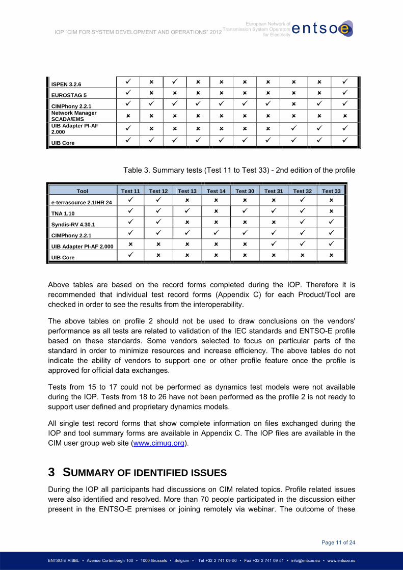
Table 3. Summary tests (Test 11 to Test 33) - 2nd edition of the profile
Tool Test 11 Test 12 Test 13 Test 14 Test 30 Test 31 Test 32 Test 33
e-terrasource 2.1IHR 24
TNA 1.10
Syndis-RV 4.30.1
CIMPhony 2.2.1
UIB Adapter PI-AF 2.000
UIB Core
Above tables are based on the record forms completed during the IOP. Therefore it is recommended that individual test record forms (Appendix C) for each Product/Tool are checked in order to see the results from the interoperability.
The above tables on profile 2 should not be used to draw conclusions on the vendors' performance as all tests are related to validation of the IEC standards and ENTSO-E profile based on these standards. Some vendors selected to focus on particular parts of the standard in order to minimize resources and increase efficiency. The above tables do not indicate the ability of vendors to support one or other profile feature once the profile is approved for official data exchanges.
Tests from 15 to 17 could not be performed as dynamics test models were not available during the IOP. Tests from 18 to 26 have not been performed as the profile 2 is not ready to support user defined and proprietary dynamics models.
All single test record forms that show complete information on files exchanged during the IOP and tool summary forms are available in Appendix C. The IOP files are available in the CIM user group web site (www.cimug.org).
3 SUMMARY OF IDENTIFIED ISSUES During the IOP all participants had discussions on CIM related topics. Profile related issues were also identified and resolved. More than 70 people participated in the discussion either present in the ENTSO-E premises or joining remotely via webinar. The outcome of these

Page 12 of 24
ENTSO-E AISBL • Avenue Cortenbergh 100 • 1000 Brussels • Belgium • Tel +32 2 741 09 50 • Fax +32 2 741 09 51 • [email protected] • www.entsoe.eu
IOP “CIM FOR SYSTEM DEVELOPMENT AND OPERATIONS” 2012
European Network of Transmission System Operators
for Electricity
discussions and agreements is summarized in the following sections as issues to be addressed to IEC, profile issues, recommendations.
3.1 ISSUES ADDRESSED TO IEC
ENTSO-E IOP identified the following issues that need to be further discussed within IEC WG13 and agreed among IEC members:
3.1.1 ISSUE IEC 1: CURVE CLASS - MISSING ATTRIBUTES
Curve class does not have the following attributes: y3Unit, y2Multiplier, y1Multiplier, y3Multiplier, xMultiplier. This attributes are missing in IEC 61970-452.
ENTSO-E IOP proposal: Add these attributes to IEC 61970-452.
3.1.2 ISSUE IEC 2: SYNCHRONOUSMACHINE CLASS - OUTDATED
ATTRIBUTES
SynchronousMachine.r and SynchronousMachine.x are present in the UML and in the profiles, but these attributes are not needed anymore. The reason is that additional attributes were added to complete the model of SynchronousMachine in respoect to short circuit and dynamics data exchanges.
ENTSO-E IOP proposal: Remove SynchronousMachine.r and SynchronousMachine.x in the UML and correct necessary standards (i.e. IEC 61970-452). In case removing these attributes from UML is not possible due to various reason the attributes should not be used in future profiles.
3.1.3 ISSUE IEC 3: EXTERNALNETWORKINJECTION.GOVERNORSCD
There is an issue with the attribute governorSCD of the class ExternalNetworkInjection. Initially, the attribute ExternalNetworkInjection.GovernorSCD was copied from GeneratingUnit together with the unit (%). As an ExternalNetworkInjection does not contain generator data the base value for the % is not given. The data type and description need to be updated to reflect the meaning of the attribute. Changes should be done in UML and in IEC 61970-452.
ENTSO-E IOP proposal: Change data type from PerCent to MW/Hz. The new description of the attribute should be: "Power Frequency Bias. This is the change in power injection divided by the change in frequency and negated. A positive value of the power frequency bias provides additional power injection upon a drop in frequency.".
3.1.4 ISSUE IEC 4: SYNCHRONOUSMACHINE.SATDIRECTTRANSX
The attribute SynchronousMachine.satDirectTransX was added to UML for short circuit data exchange but this attribute is not required for short circuit data exchange according to IEC
Page 13 of 24
ENTSO-E AISBL • Avenue Cortenbergh 100 • 1000 Brussels • Belgium • Tel +32 2 741 09 50 • Fax +32 2 741 09 51 • [email protected] • www.entsoe.eu
IOP “CIM FOR SYSTEM DEVELOPMENT AND OPERATIONS” 2012
European Network of Transmission System Operators
for Electricity
60909. The description of the attribute should indicate this. Changes should be done in UML and in IEC 61970-452.
ENTSO-E IOP proposal: The new description of the attribute should be: "Saturated Direct-axis transient reactance. The attribute is primarily used for short circuit calculations according to ANSI.".
3.1.5 ISSUE IEC 5: EXTERNALNETWORKINJECTION.MAXP
ENTSO-E IOP proposal: The description of the attribute should be: "Maximum active power of the injection.".
3.1.6 ISSUE IEC 6: EXTERNALNETWORKINJECTION.MINP
ENTSO-E IOP proposal: The description of the attribute should be: "Minimum active power of the injection.".
3.1.7 ISSUE IEC 7: SYNCHRONOUSMACHINE.SHORTCIRCUITROTORTYPE
ENTSO-E IOP proposal: The description of the attribute should be: "Type of rotor, used by short circuit applications, only for single fed short circuit according to IEC 60909.".
3.1.8 ISSUE IEC 8: TRANSFORMER MODEL
Some vendors expressed their concern that the new transformer model is difficult to handle. It is also understood that changes in the model will impact a lot of implementations. Vendors pointed out that it is difficult to restrict that each transformer is modelled always from high voltage to low voltage. Some projects see a value to know that TransformerEnd.endNumber specifies which the highest voltage side is. There is need to consider transmission-distribution transformers in case the two windings are the same voltage.
ENTSO-E IOP proposal: The description of TransformerEnd.endNumber specifies that "Highest voltage winding should be 1.". The recommendation is to delete this sentence as it is considered as redundant information.
3.1.9 ISSUE IEC 9: NAME, NAMETYPE ISSUE.
During the IOP preparatory phase a lot of concerns on the use of Name, NameType and NameTypeAuthority classes were expressed. IEC Standards do not define clear enough the use of this construction. It was pointed out that Name-NameType construction is intended as an alternative to Naming (identifier) service to handle system that is not compliant with the use of rdf:ID as object identifier. In the process of ENTSO-E profile preparation it was agreed that Name, NameType, NameTypeAuthority will not be used in the frozen version of the profile. It could stay in the profile in order to serve some of the use cases and be compatible with 61970-452. All names were added as ENTSO-E extensions to the IdentifiedObject and these will be the main one to be used in the frozen version of the profile.

Page 14 of 24
ENTSO-E AISBL • Avenue Cortenbergh 100 • 1000 Brussels • Belgium • Tel +32 2 741 09 50 • Fax +32 2 741 09 51 • [email protected] • www.entsoe.eu
IOP “CIM FOR SYSTEM DEVELOPMENT AND OPERATIONS” 2012
European Network of Transmission System Operators
for Electricity
ENTSO-E IOP proposal: Remove Name, NameType, NameTypeAuthority from the 61970-452 or clearly specify the use and recommend how profiles compatible with 61970-452 should deal with name extensions (extensions to the IdentifiedObject).
3.1.10 ISSUE IEC 10: CLARIFICATION REGARDING RDF:ID AND MRID
During the IOP preparatory phase an issue on rdf:ID and mRID was identified. IEC WG13 took some actions and discussed the issue but was not able to reach agreement before the IOP. Some TSOs and vendors are using rdf:ID as their internal identifier, which is not necessarily GUID or UUID type. The argument for not using UUID is that the exchanging party would need to store the rdf:ID in its database as it need to be persistent. This will require additional effort to maintain rdf:ID specific IDs in all databases of TSOs or vendors.
ENTSO-E IOP proposal: Try to reach consensus and clarify this issue in the CIM standards before the release of standards related to CIM16.
3.1.11 ISSUE IEC 11: SHUNTCOMPENSATOR
There is a challenge to model variable shunt reactor regulated through a tap changer, e.g. 400 kV, 120-200 MVAr, regulated in 25 steps, Non-linear MVAR-change per step. CIM does not allow 1:1 model of this component. This problem exists in both EMS and planning model environments. It is also difficult to model regulating control correctly when splitting the shunt into several units.
ENTSO-E IOP proposal: It is recommended that WG13 implement lookup table with impedance per step. WG13 to consult with ENTSO-E on the right model to be implemented in CIM.
3.1.12 ISSUE IEC 12: ROUNDING ISSUE - DIFFERENCE FILES
During the IOP an issue related to rounding of numbers was identified. There is no way to specify that 0.000123967 is the same value as 0.0001239669509. With 61970-552, the values need to match exactly in order to allow modification of a value, deletion of an instance or execution of a difference file (reverses are actually pre-conditions).
ENTSO-E IOP proposal: It is recommended that some degree of flexibility should be specified in 61970-552 in order to make possible to apply the standard in correct way and avoid confusion.
3.1.13 ISSUE IEC 13: USE OF BAY CLASS
Some IOP test models used Bay class in a way it has never been used before. This caused some confusion in the IOP and was also considered as a gap in the CIM Standards.
ENTSO-E IOP proposal: It is recommended that the use of Bay class in SCADA/EMS type of models is clarified before the release of CIM16 related standards.
Page 15 of 24
ENTSO-E AISBL • Avenue Cortenbergh 100 • 1000 Brussels • Belgium • Tel +32 2 741 09 50 • Fax +32 2 741 09 51 • [email protected] • www.entsoe.eu
IOP “CIM FOR SYSTEM DEVELOPMENT AND OPERATIONS” 2012
European Network of Transmission System Operators
for Electricity
3.1.14 ISSUE IEC 14: CONNECTIVITYNODE IN LINE
According to ENTSO-E profile validation tools require a ConnectivityNode to be in a VoltageLevel, but Lines are not allowed to have VoltageLevels. The current validation logic is the following: If the model is a TSO EQ, the ConnectivityNodes should be grouped under VoltageLevel; If the model is a Boundary EQ, the ConnectivityNodes should be grouped under Line; If the model is a merged one, the ConnectivityNodes can be grouped under either VoltageLevel or Line.
ENTSO-E IOP proposal: WG13 to clarify the containership and see if the validation rules are applied correctly. Necessary explanations in 61970-452 should be given.
3.1.15 ISSUE IEC 15: DIFFERENT DEVICES ON THE SAME REGULATING
CONTROL
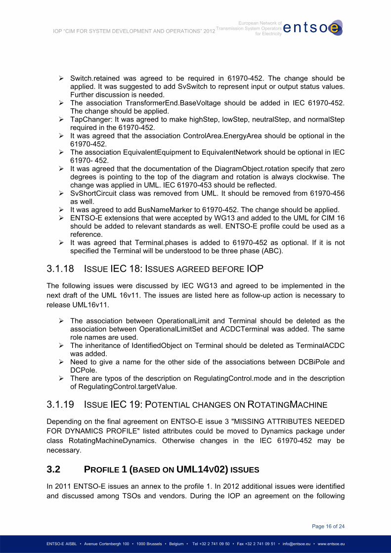
During the IOP the issue on what type the regulating control (RegulatingControl or TapChangerControl) should have if devices of different types use the same regulating control was identified. A small diagram is provided below.
ENTSO-E IOP proposal: WG13 to clarify the issue. Necessary explanations in 61970-452 should be given.
3.1.16 ISSUE IEC 16: GENERATINGUNIT, FUEL TYPES ISSUE
In the preparation phase of the IOP, WG13 and ENTSO-E discussed various possibilities to extend the model in order to cover different generating units and fuel types. Some of the items were finalized, but other like solar, marine and the connection of wind model (dynamics and wires packages) are still open.
ENTSO-E IOP proposal: WG13 to finalize the discussion before the release of CIM16.
3.1.17 ISSUE IEC 17: ISSUES FROM IOP2011
The following issues were discussed by IEC WG13 and agreed. Necessary changes were done in the UML for CIM 16. The issues are listed here as follow-up action is necessary to apply the changes in IEC Standards.
PhaseTapChangerNonLinear.xMedian was replaced with xMin. It should be reflected in the text on 61970-301.
Shunt
RegulatingControl
Page 16 of 24
ENTSO-E AISBL • Avenue Cortenbergh 100 • 1000 Brussels • Belgium • Tel +32 2 741 09 50 • Fax +32 2 741 09 51 • [email protected] • www.entsoe.eu
IOP “CIM FOR SYSTEM DEVELOPMENT AND OPERATIONS” 2012
European Network of Transmission System Operators
for Electricity
Switch.retained was agreed to be required in 61970-452. The change should be applied. It was suggested to add SvSwitch to represent input or output status values. Further discussion is needed.
The association TransformerEnd.BaseVoltage should be added in IEC 61970-452. The change should be applied.
TapChanger: It was agreed to make highStep, lowStep, neutralStep, and normalStep required in the 61970-452.
It was agreed that the association ControlArea.EnergyArea should be optional in the 61970-452.
The association EquivalentEquipment to EquivalentNetwork should be optional in IEC 61970- 452.
It was agreed that the documentation of the DiagramObject.rotation specify that zero degrees is pointing to the top of the diagram and rotation is always clockwise. The change was applied in UML. IEC 61970-453 should be reflected.
SvShortCircuit class was removed from UML. It should be removed from 61970-456 as well.
It was agreed to add BusNameMarker to 61970-452. The change should be applied. ENTSO-E extensions that were accepted by WG13 and added to the UML for CIM 16
should be added to relevant standards as well. ENTSO-E profile could be used as a reference.
It was agreed that Terminal.phases is added to 61970-452 as optional. If it is not specified the Terminal will be understood to be three phase (ABC).
3.1.18 ISSUE IEC 18: ISSUES AGREED BEFORE IOP
The following issues were discussed by IEC WG13 and agreed to be implemented in the next draft of the UML 16v11. The issues are listed here as follow-up action is necessary to release UML16v11.
The association between OperationalLimit and Terminal should be deleted as the association between OperationalLimitSet and ACDCTerminal was added. The same role names are used.
The inheritance of IdentifiedObject on Terminal should be deleted as TerminalACDC was added.
Need to give a name for the other side of the associations between DCBiPole and DCPole.
There are typos of the description on RegulatingControl.mode and in the description of RegulatingControl.targetValue.
3.1.19 ISSUE IEC 19: POTENTIAL CHANGES ON ROTATINGMACHINE
Depending on the final agreement on ENTSO-E issue 3 "MISSING ATTRIBUTES NEEDED FOR DYNAMICS PROFILE" listed attributes could be moved to Dynamics package under class RotatingMachineDynamics. Otherwise changes in the IEC 61970-452 may be necessary.
3.2 PROFILE 1 (BASED ON UML14V02) ISSUES
In 2011 ENTSO-E issues an annex to the profile 1. In 2012 additional issues were identified and discussed among TSOs and vendors. During the IOP an agreement on the following

Page 17 of 24
ENTSO-E AISBL • Avenue Cortenbergh 100 • 1000 Brussels • Belgium • Tel +32 2 741 09 50 • Fax +32 2 741 09 51 • [email protected] • www.entsoe.eu
IOP “CIM FOR SYSTEM DEVELOPMENT AND OPERATIONS” 2012
European Network of Transmission System Operators
for Electricity
items was reached and the annex to profile 1 was extended and published on the ENTSO-E web site:
• Slack bus is a given node of GeneratingUnit with NormalPF which is mandatory (at least one GeneratingUnit.NormalPF equals 1). Additional information is provided optionally by TopologicalIsland.AngleRef_TopologicalNode. More than one slack node (i.e. distributed slack nodes) is allowed.
• Terminal.SequenceNumber is mandatory for any ConductingEquipment that has more than one Terminal (e.g. ACLineSegment, Switch, TransformerWinding, etc.).
• TapChanger.NeutralU: To precise definition the ‘RatedU at neutral settings’ should be a value (e.g. 400kV). The source is the test report.
• TapChanger.lowStep and TapChanger.highStep can be negative and tools issue to handle this issue. TapChanger.highStep should be bigger than TapChanger.lowStep. TapChanger.highStep cannot be equal to TapChanger.lowStep.
• For symmetrical phase shifting transformers having constant impedance or voltage the phase shift cannot be given by using VoltageStepIncrementOutOfPhase and should thus be set to 0. The PhaseTapChanger.stepPhaseShiftIncrement should be used given in AngleDegrees.
• (+1)Y2 in the following diagram should be (-1)Y2.
• TopologicalNode.ControlArea is optional.
3.3 PROFILE 2 (BASED ON UML16V10) ISSUES
Some profile related issues were identified during the IOP. These issues were applied on the 2nd edition of the ENTSO-E CIM Profile, IOP version issued on 3 July 2012. The issues listed in this section have been resolved during the IOP. The decisions were taken among all IOP participants. In the updated version of the 2nd edition of the ENTSO-E CIM Profile [3], issued on 26 August 2012, all issues described in this section are corrected.
3.3.1 ISSUE ENTSO-E 1: VSCCAPABILITYCURVE CLASS INHERITED
ATTRIBUTES
The following attributes of VSCCapabilityCurve class: y3Unit, y2Multiplier, y1Multiplier, y3Multiplier, xMultiplier should be removed from VSCCapabilityCurve and inherit from Curve
Page 18 of 24
ENTSO-E AISBL • Avenue Cortenbergh 100 • 1000 Brussels • Belgium • Tel +32 2 741 09 50 • Fax +32 2 741 09 51 • [email protected] • www.entsoe.eu
IOP “CIM FOR SYSTEM DEVELOPMENT AND OPERATIONS” 2012
European Network of Transmission System Operators
for Electricity
class. This profile issue is related to issue IEC 1, but the changes in the profile are already made.
Applied change to the profile: The attributes y3Unit, y2Multiplier, y1Multiplier, y3Multiplier, xMultiplier were removed from the Equipment profile. These attributes were added to Curve class as optional attributes.
3.3.2 ISSUE ENTSO-E 2: SYNCHRONOUSMACHINE R AND X
Applied change to the profile: SynchronousMachine.r and SynchronousMachine.x were removed from the Equipment profile. The issue is related to issue IEC 2.
3.3.3 ISSUE ENTSO-E 3: MISSING ATTRIBUTES NEEDED FOR DYNAMICS
PROFILE
RotatingMachine class does not have the following attributes: damping, inertia, saturationFactor, saturationFactor120, statorLeakageReactance, statorResistance
Applied change to the profile: Above attributes were added as required attributes and with stereotype "Dynamics" to the RotatingMachine class in the Equipment profile.
Further change may be applied if it is decided that a class RotatingMachineDynamics will be created in the Dynamics package.
3.3.4 ISSUE ENTSO-E 4: SHORTCIRCUIT CLASSES AND ATTRIBUTES
Classes and attributes related to short circuit data exchange were clarified during the IOP. Applied changes to the equipment profile are as follows:
The stereotype of class ExternalNetworkInjection is removed as this class can be used in a regular load flow exchange.
The following attributes of ExternalNetworkInjection have not stereotype ShortCircuit: governorSCD, maxP, maxQ, minP, minQ and referencePriority.
The cardinality of the following attributes of ExternalNetworkInjection was changed to required as these attributes are required only for load flow exchange: governorSCD, maxP, maxQ, minP, minQ and referencePriority.
The following attributes of ExternalNetworkInjection have stereotype ShortCircuit and the cardinality was changed to required: minZ0ToZ1Ratio, minR1ToX1Ratio, minR0ToX0Ratio, maxZ0ToZ1Ratio, maxR1ToX1Ratio, maxR0ToX0Ratio, maxInitialSymShCCurrent, minInitialSymShCCurrent.
The cardinality of the following attributes of ACLineSegment was changed to required: b0ch, g0ch, shortCircuitEndTemperature, r0, x0.
The cardinality of the following attributes of AsynchronousMachine was changed to required: converterFedDrive, efficiency, iaIrRatio, polePairNumber, ratedMechanicalPower, reversible.
The cardinality of the following attributes of EquivalentBranch was changed to required: negativeR12, negativeR21, zeroR21, zeroR12, positiveR12, positiveR21, positiveX12, negativeX21, negativeX12, zeroX12, zeroX21, positiveX21.
Page 19 of 24
ENTSO-E AISBL • Avenue Cortenbergh 100 • 1000 Brussels • Belgium • Tel +32 2 741 09 50 • Fax +32 2 741 09 51 • [email protected] • www.entsoe.eu
IOP “CIM FOR SYSTEM DEVELOPMENT AND OPERATIONS” 2012
European Network of Transmission System Operators
for Electricity
The cardinality of the following attributes of EquivalentInjection was changed to required: r, r0, r2, x, x0, x2.
The cardinality of PowerTransformer.isPartOfGeneratorUnit was changed to required. The cardinality of the following attributes of PowerTransformerEnd was changed to
required: b0, g0, r0, x0, phaseAngleClock. The cardinality of the following attributes of SeriesCompensator was changed to
required: r0, x0. The cardinality of the following attributes of ShuntCompensator was changed to
required: b0PerSection, g0PerSection. The cardinality of the following attributes of SynchronousMachine was changed to
required: earthing, equivalentResistance, r0, r2, x0, x2, satDirectSubtransX. The following note was added to SynchronousMachine: “If
SynchronousMachine.earthing is true, then SynchronousMachine.earthingStarPointR and SynchronousMachine.earthingStarPointX are required".
The cardinality of the TransformerEnd.grounded was changed to required. The following note was added to TransformerEnd: "If TransformerEnd.grounded is
true, then TransformerEnd.rground and TransformerEnd.xground are required". The profile document specifies that "In case classes/attributes have stereotype
‘ShortCircuit’, then their cardinality shall be valid for ShortCircuit data exchange.".
3.3.5 ISSUE ENTSO-E 5: DIAGRAM LAYOUT: VISIBILITYLAYER
Applied change to the profile: The class VisibilityLayer inherits from IdentifiedObject, i.e. uses name attribute from IdentifiedObject.
3.3.6 ISSUE ENTSO-E 6: DIAGRAM LAYOUT: DIAGRAMOBJECTSTYLE
Applied change to the profile: The class DiagramObjectStyle inherits from IdentifiedObject, i.e. uses name attribute from IdentifiedObject.
4 CONCLUSIONS AND RECOMMENDATIONS The conclusions of the ENTSO-E Interoperability test “CIM for System development and Operations” 2012 can be summarized as follows:
Various vendors that provide tools for “system operational” environment as well as for “system planning” environment attended ENTSO-E IOP and validated the 3rd draft version (version 2.3) of the 2nd edition of the ENTSO-E CIM Profile.
The IOP successfully tested the most important features of the ENTSO-E CIM Profiles. Test procedures and test models were validated for further use.
The 2nd edition of the ENTSO-E CIM profile has a wide scope and it is based on the latest IEC draft standards and fully covers all classes and definitions described in IEC 61970-452 (CPSM profile), 61970-456, 61970-453, etc. The profile was created in UML environment, which facilitates maintenance process.
Page 20 of 24
ENTSO-E AISBL • Avenue Cortenbergh 100 • 1000 Brussels • Belgium • Tel +32 2 741 09 50 • Fax +32 2 741 09 51 • [email protected] • www.entsoe.eu
IOP “CIM FOR SYSTEM DEVELOPMENT AND OPERATIONS” 2012
European Network of Transmission System Operators
for Electricity
TSO experts tested the ENTSO-E Network Modelling Database (NMD), which has been recently developed. Issues were found in both NMD and TSOs' models. Most of the issues were resolved during the IOP. The remaining issues were recorded for further analysis and fixes.
The outcome of the test and the final post IOP version of the 2nd edition of the ENTSO-E CIM profile developed in preparation stage are a solid basis for further ENTSO-E discussion in accordance with the ENTSO-E roadmap for future implementation of the updates to the ENTSO-E CIM profile. A fast switch to the 2nd edition of the ENTSO-E CIM profile is recommended and it will make possible for the TSO's to utilize the model exchange properly.
Important issues to be addressed to IEC/WG13 as well as profile related issues were identified and discussed. ENTSO-E IOP participants agreed on proposals to IEC/WG13 that are listed in this report.
ENTSO-E and ENTSO-E IOP participants expect that the following items will be treated with high priority and included in the updated version of IEC CIM Standards (items sorted by priority):
o Exchange of operational state profile. The issue was discussed in the preparatory phase of the IOP 2012, but agreement has not been reached ahead of the IOP in order to perform testing. The approach on exchange of operational state profile is very important for TSOs' use cases especially for frequent exchanges as Day-Ahead Congestion Forecast process. The way how operational states are exchanged should utilise current partitioning of the data in order to exchange the data in an efficient way. IOP participants expressed their concern that adding more profiles would lead to more confusion and will be difficult to interoperate. Preference to have extension (related to target values and controls) in State Variables profile was given. On the other hand putting a lot of attributes in one profile leads to a lot of optional attributes, which may also complicate. The following related issues should also be resolved:
State Variables profile mixes input and output data for the load flow;
There is no way to export a model which is not solved;
Breaker status is in the Topology profile and currently there is a problem to exchange breaker status.
o CIM should allow adequate modelling of HVDC links and their controls. In the preparation stage of the IOP ENTSO-E included the draft version of the classes related to HVDC modelling. The HVDC model is developed based on the information by IEC TC22. Last specification from IEC TC22 was available in May 2012. IEC WG13 should further revise the HVDC model in order to be compatible with the IEC TC22 requirements. HVDC modelling is rapidly

Page 21 of 24
ENTSO-E AISBL • Avenue Cortenbergh 100 • 1000 Brussels • Belgium • Tel +32 2 741 09 50 • Fax +32 2 741 09 51 • [email protected] • www.entsoe.eu
IOP “CIM FOR SYSTEM DEVELOPMENT AND OPERATIONS” 2012
European Network of Transmission System Operators
for Electricity
developing and it is a challenge for CIM to follow all necessary updates. Some IOP participants expressed their concern that HVDC model is modelled in a very complex way. TC22 is also working on dynamics and short circuit model for HVDC and precise definitions are expected in the future. Therefore, IOP participants recommended IEC WG13 to review the existing version of the model in UML to ensure that the HVDC model is in line with TC22 documentation. The review is expected in September 2012. Then step by step approach could be applied to first cover existing HVDC technologies. Similar to the dynamics data the implementation of the HVDC model will be difficult to be done by vendors as long as the standard is a draft standard. In addition most of the vendors involved currently in the standardization are mostly EMS vendors, i.e. different kind of models are used. A forum to discuss with "planning" vendors and also with TC22 experts is necessary.
o Update of the CIM standard in order to cover exchange of dynamics data. ENTSO-E took an active role in the EPRI project "CIM for Dynamics" (Phase 2), which started in Sep 2011. The project focused on standard interconnections and standard models exchange. Standard models classes have a list of attributes based on IEEE, IEC, WECC, ENTSO-E, etc. models. IEC draft standard (IEC 61400-27-1) on wind turbines modelling is also implemented in the current draft UML and in the ENTSO-E profile. Classes for user defined and proprietary models are expected to be cleaned. It is not sure to what extend this will be covered by the current EPRI project. Unfortunately no vendor was able to implement parts of the dynamics data exchange profile ahead of the IOP and therefore no tests and profile validations were performed in the ENTSO-E IOP. IOP participants pointed out that standardization is a voluntary work and it is difficult to cope with the need of the industry. It is very difficult to implement a standard when it is at stage of a draft standard; the effort to develop valuable test models is significant. Therefore, IOP participants concluded that there should be a way to fund at least some of the tasks in order to validate the correctness of the draft standard. Testing will not be possible without funding.
o Exchange of project information together with the models. Exchange of project information would be a valuable addition of the models exchange. There are a lot of processes that would benefit on this one. ENTSO-E Ten Year Network Development Plan (TYNDP) is one of them. CIM would support such functionality by applying difference file exchange, which may need to be restricted in order not to complicate the exchange. Project information exchange should be valid for full files as well. Further discussion between ENTSO-E and WG13 is necessary to agree on the scope and use cases.
o Adequate methods for exchange of the specification of different profiles between existing tools should be agreed and standardized in order to allow error free interpretation of profile definitions by tools that create the profiles and validate instance data against these profiles.
Page 22 of 24
ENTSO-E AISBL • Avenue Cortenbergh 100 • 1000 Brussels • Belgium • Tel +32 2 741 09 50 • Fax +32 2 741 09 51 • [email protected] • www.entsoe.eu
IOP “CIM FOR SYSTEM DEVELOPMENT AND OPERATIONS” 2012
European Network of Transmission System Operators
for Electricity
o Collection of use cases and covering exchanges between transmission and distribution systems is necessary in order to create an adequate data exchange profiles between transmission and distribution. These profiles should be linked as much as possible with existing profiles to avoid overlap of data exchanges.
The following recommendations were agreed:
Continuous maintenance of the ENTSO-E profile is necessary in order to facilitate IOP preparation work.
ENTSO-E CIM exchanges define that so called X-nodes, which are present in the boundary set and connect two Model Authority Sets, should be placed on the electrical middle of the tie-lines, i.e. not on the country or TSO border. IOP participants raised this issue and requested further ENTSO-E discussion on this topic. The recommendation is to allow the location of the X-nodes or boundary set information to be defined by the two concerned TSOs. Based on this agreement the information will be maintained in the ENTSO-E Network Modelling Database. Such setup would allow TSOs to use identical models for various exchange processes and therefore optimize model maintenance efforts.
ENTSO-E should revise the naming convention. There are some restrictions on IdentifiedObject.name/description for classes like TopologicalNode, VoltageLevel, etc. IOP participants pointed out that vendors should be able to support whatever is agreed by the users and that these restrictions do not have much sense taking into account how data is treated nowadays. Therefore this issue requires further ENTSO-E discussion in order to reach agreement between TSOs. The change could be applied at the moment the 2nd profile is approved.
The profile to be used in the IOP should be fixed well ahead of the on-site test. In order to achieve this goal substantial commitment by vendors and IEC/WG13 is expected during the process of updating of IEC standards and revising the definitions in the draft versions of the profiles.
IEC CIM standards should have stable development roadmap as much as possible. Features that have been already implemented and used in real data exchanges should be kept unchanged in case no significant problem is found. Necessary major changes should be properly documented and presented to wider auditory in order to receive wide acceptance ahead of issuing of the updated IEC CIM standards. It is recommended that CIM user group also takes a role and implements a process to ensure this.
IEC, CIM user group and ENTSO-E should work in close cooperation to define CIM/XML test files that cover as much use cases as possible. It is preferable that these test files are referenced in the IEC CIM standards.

Page 23 of 24
ENTSO-E AISBL • Avenue Cortenbergh 100 • 1000 Brussels • Belgium • Tel +32 2 741 09 50 • Fax +32 2 741 09 51 • [email protected] • www.entsoe.eu
IOP “CIM FOR SYSTEM DEVELOPMENT AND OPERATIONS” 2012
European Network of Transmission System Operators
for Electricity
Exchange of test models created by vendors is necessary in order to simulate exchanges of real data as much as possible. Each tool has its special functionalities that are often used by users during the real data exchanges to model different parts on the power system. The usage of different modelling approaches that are in most cases tool dependent creates difficulties when applying CIM in real data exchange in case the conversion process related to these specific functionalities have not been properly tested during an IOP. It is recommended that all vendors publish their test models valid for existing CIM profiles and maintain them.
5 REFERENCES [1] Reference Manual for Exchanging Standard Power System Dynamic Models: Based
on the IEC 61970 Common Information Model (CIM). EPRI, Palo Alto, CA: 2009. 1020200.
[2] ENTSO-E CIM Profile, ENTSO-E CIM Model Exchange, 1st edition version 10 May 2009 and the annex published after the ENTSO-E IOP 2012.
[3] ENTSO-E CIM Profile, ENTSO-E CIM Model Exchange, 2nd edition, version 3 Sep 2012.
Page 24 of 24
ENTSO-E AISBL • Avenue Cortenbergh 100 • 1000 Brussels • Belgium • Tel +32 2 741 09 50 • Fax +32 2 741 09 51 • [email protected] • www.entsoe.eu
IOP “CIM FOR SYSTEM DEVELOPMENT AND OPERATIONS” 2012
European Network of Transmission System Operators
for Electricity
6 APPENDIX A: INFORMATION ON TOOLS TESTED/USED IN
THE IOP Appendix A is included as a separate file.
7 APPENDIX B: TEST PROCEDURES Appendix B is included as a separate file.
8 APPENDIX C: TEST RECORD FORMS Appendix C is included as a separate file.
![ETSI ISG CIM · [JSON-LD] 20170608 Introduction to ISG CIM CIM-002-UC CIM -003 GAP CIM-004-APIprelim CIM-005-DPP CIM-001-AB ) CIM-006-MOD0. Timeline in ToR 02/2017 First General Meeting](https://img.pdfslide.net/doc/110x75/6002860fd1e0f63f360db5f2/etsi-isg-cim-json-ld-20170608-introduction-to-isg-cim-cim-002-uc-cim-003-gap.jpg)