Embed Size (px)
Citation preview

TECHNICAL REPORT
© The Broadband Forum. All rights reserved.
.
TR-060 Interoperability test Plan for SHDSL
Issue: 2.0 Issue Date: February 2005

Interoperability Test Plan for SHDSL TR-060 Issue 2
January 2005 © The Broadband Forum. All rights reserved. 2
Notice The Broadband Forum is a non-profit corporation organized to create guidelines for broadband network system development and deployment. This Broadband Forum Technical Report has been approved by members of the Forum. This Broadband Forum Technical Report is not binding on the Broadband Forum, any of its members, or any developer or service provider. This Broadband Forum Technical Report is subject to change, but only with approval of members of the Forum. This Technical Report is copyrighted by the Broadband Forum, and all rights are reserved. Portions of this Technical Report may be copyrighted by Broadband Forum members. This Broadband Forum Technical Report is provided AS IS, WITH ALL FAULTS. ANY PERSON HOLDING A COPYRIGHT IN THIS BROADBAND FORUM TECHNICAL REPORT, OR ANY PORTION THEREOF, DISCLAIMS TO THE FULLEST EXTENT PERMITTED BY LAW ANY REPRESENTATION OR WARRANTY, EXPRESS OR IMPLIED, INCLUDING, BUT NOT LIMITED TO, ANY WARRANTY: (A) OF ACCURACY, COMPLETENESS, MERCHANTABILITY, FITNESS FOR A
PARTICULAR PURPOSE, NON-INFRINGEMENT, OR TITLE; (B) THAT THE CONTENTS OF THIS BROADBAND FORUM TECHNICAL
REPORT ARE SUITABLE FOR ANY PURPOSE, EVEN IF THAT PURPOSE IS KNOWN TO THE COPYRIGHT HOLDER;
(C) THAT THE IMPLEMENTATION OF THE CONTENTS OF THE DOCUMENTATION WILL NOT INFRINGE ANY THIRD PARTY PATENTS, COPYRIGHTS, TRADEMARKS OR OTHER RIGHTS.
By using this Broadband Forum Technical Report, users acknowledge that implementation may require licenses to patents. The Broadband Forum encourages but does not require its members to identify such patents. For a list of declarations made by Broadband Forum member companies, please see http://www.broadband-forum.org. No assurance is given that licenses to patents necessary to implement this Technical Report will be available for license at all or on reasonable and non-discriminatory terms. ANY PERSON HOLDING A COPYRIGHT IN THIS BROADBAND FORUM TECHNICAL REPORT, OR ANY PORTION THEREOF, DISCLAIMS TO THE FULLEST EXTENT PERMITTED BY LAW (A) ANY LIABILITY (INCLUDING DIRECT, INDIRECT, SPECIAL, OR CONSEQUENTIAL DAMAGES UNDER ANY LEGAL THEORY) ARISING FROM OR RELATED TO THE USE OF OR RELIANCE UPON THIS TECHNICAL REPORT; AND (B) ANY OBLIGATION TO UPDATE OR CORRECT THIS TECHNICAL REPORT. Broadband Forum Technical Reports may be copied, downloaded, stored on a server or otherwise re-distributed in their entirety only, and may not be modified without the advance written permission of the Broadband Forum. The text of this notice must be included in all copies.
Interoperability Test Plan for SHDSL TR-060 Issue 2
January 2005 © The Broadband Forum. All rights reserved. 3
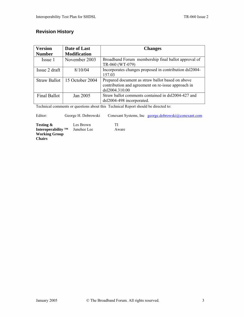
Revision History Version Number
Date of Last Modification
Changes
Issue 1 November 2003 Broadband Forum membership final ballot approval of TR-060 (WT-079)
Issue 2 draft 8/10/04 Incorporates changes proposed in contribution dsl2004-157.03
Straw Ballot 15 October 2004 Prepared document as straw ballot based on above contribution and agreement on re-issue approach in dsl2004.310.00
Final Ballot Jan 2005 Straw ballot comments contained in dsl2004-427 and dsl2004-498 incorporated.
Technical comments or questions about this Technical Report should be directed to: Editor: George H. Dobrowski Conexant Systems, Inc [email protected]
Les Brown TI Testing & Interoperability ™ Working Group Chairs
Junehee Lee Aware

Interoperability Test Plan for SHDSL TR-060 Issue 2
January 2005 © The Broadband Forum. All rights reserved. 4
Table of Contents
1 INTRODUCTION..................................................................................................... 7
2 SCOPE ....................................................................................................................... 7
3 TEST SETUP ............................................................................................................ 8 3.1 TYPICAL TEST SETUP ............................................................................................. 9 3.2 STU MONITORING EQUIPMENT.............................................................................. 9 3.3 TEST LOOPS.......................................................................................................... 10 3.4 GROUP TEST TYPICAL SETUP ............................................................................... 10 3.5 TEST BIT RATES ................................................................................................... 10
4 TEST PROCEDURE.............................................................................................. 11 4.1 TEST VALIDATION................................................................................................ 11 4.2 CONFORMANCE TESTING...................................................................................... 11
4.2.1 Transmit Power Level ............................................................................... 12 4.2.2 Power Spectral Density (PSD) Tests ........................................................ 13 4.2.3 Power Back Off (PBO) Tests .................................................................... 13 4.2.4 Impedance of the Transceiver................................................................... 15 4.2.5 Unbalance about Earth – LCL.................................................................. 15 4.2.6 Unbalance about Earth – LOV ................................................................. 16 4.2.7 Power Feeding and Wetting Current (if implemented)............................. 16
4.2.7.1 Wetting Current................................................................................................... 16 4.2.7.2 Polarity ................................................................................................................ 16 4.2.7.3 Maximum Power Consumption (load) ................................................................ 17 4.2.7.4 Maximum Power Provision (source)................................................................... 17 4.2.7.5 Reset of the CPE.................................................................................................. 17 4.2.7.6 DC and low frequency AC termination of the NTU ........................................... 17
4.2.8 Frame BIT Tests........................................................................................ 18 4.2.8.1 Frame Bit compatibility....................................................................................... 18
4.2.9 Overall Activation Test to Reach Data Mode ........................................... 18 4.3 PHYSICAL LAYER INTEROPERABILITY .................................................................. 21
4.3.1 Test Setup.................................................................................................. 21 4.3.2 Activation– Short Loops............................................................................ 22
4.3.2.1 Zero Loop BER Data Transfer ............................................................................ 22 4.3.2.2 Re-Initialisation after Break-Down – Short Loops ............................................. 23 4.3.2.3 Micro-Interruptions ............................................................................................. 23 4.3.2.4 No Common Mode Test ...................................................................................... 23
4.3.3 Activation Tests Over Various Test Loops................................................ 25 4.3.3.1 Activation – Test Loops Annex A....................................................................... 25 4.3.3.2 Activation – Test Loops Annex B....................................................................... 29
4.4 NOISE PERFORMANCE .......................................................................................... 34 4.4.1 Test Configuration .................................................................................... 34 4.4.2 Test Procedure .......................................................................................... 35 4.4.3 Expected Result......................................................................................... 35
Interoperability Test Plan for SHDSL TR-060 Issue 2
January 2005 © The Broadband Forum. All rights reserved. 5
4.5 LINE PROBE TESTING (RATE ADAPTIVE MODE TESTING) .................................... 37 4.5.1 Test Configuration .................................................................................... 37 4.5.2 Method of Procedure ................................................................................ 37 4.5.3 Expected Result......................................................................................... 38 4.5.4 Test Configuration .................................................................................... 39 4.5.5 Method of Procedure ................................................................................ 39 4.5.6 Expected Result......................................................................................... 40
4.6 PMMS (PROBE TESTING) COMPLIANCE TESTS .................................................... 41 4.6.1 PMMS Timing compliance test ................................................................. 42
4.6.1.1 Expected Results ................................................................................................. 42 4.6.2 PMMS Signal Compliance Test ................................................................ 44
Test setup .......................................................................................................................... 44 4.6.2.1 Expected results................................................................................................... 45
4.7 4-WIRE MODE...................................................................................................... 45 4.7.1 4-Wire Mode start-up description............................................................. 45 4.7.2 4-Wire Mode start-up description with Lineprobing ................................ 46 4.7.3 Test Setup.................................................................................................. 48
5 SYSTEM INTEROPERABILITY ........................................................................ 49 5.1 LOOP BACK CONTROL STRUCTURE TESTS ............................................................ 50
5.1.1 CO Control Mode ..................................................................................... 50 5.1.1.1 CO Control Mode: System Loop back Message (9) Broadcast .......................... 50
5.1.1.1.1 Network Loop back at Remote ....................................................... 50 5.1.1.1.2 Customer Loop back at Remote...................................................... 52 5.1.1.1.3 Bi-directional Loop back at Remote (If supported by both ends) .. 53 5.1.1.1.4 Special Loop back at Remote (if supported)................................... 55
5.1.1.2 CO Control Mode: Element Loop back Message (10)........................................ 56 5.1.1.2.1 Network Loop back at Remote ....................................................... 56 5.1.1.2.2 Customer Loopback at Remote....................................................... 57 5.1.1.2.3 Bi-directional Loopback at Remote (If supported by both ends) ... 59 5.1.1.2.4 Special Loopback at Remote (if supported).................................... 60
5.1.1.3 CO Control Mode: CO Loopback: Remote Display ........................................... 62 5.1.1.3.1 Network Loopback at CO ............................................................... 62 5.1.1.3.2 Customer Loopback at CO.............................................................. 62 5.1.1.3.3 Bi-Directional Loopback at CO...................................................... 63
5.1.2 Remote Control Mode ............................................................................... 64 5.1.2.1 Remote Control Mode: System Loop back Message (Msg id 9) ........................ 64
5.1.2.1.1 Network Loop back at CO .............................................................. 64 5.1.2.1.2 Customer Loopback at CO.............................................................. 66 5.1.2.1.3 Bi-directional Loopback at CO (if supported by both ends)........... 67 5.1.2.1.4 Network Loopback at Remote using CO control............................ 69 5.1.2.1.5 Customer Loopback at Remote using CO control .......................... 71 5.1.2.1.6 Bi-directional Loopback at Remote using CO control (if supported by both ends)..................................................................................................... 73
5.1.2.2 Remote Control Mode: Element Loop back Message (Msg id 10)..................... 75 5.1.2.2.1 Network Loop back at CO .............................................................. 76 5.1.2.2.2 Customer Loopback at CO.............................................................. 77

Interoperability Test Plan for SHDSL TR-060 Issue 2
January 2005 © The Broadband Forum. All rights reserved. 6
5.1.2.2.3 Bi-directional Loopback at CO (if supported by both ends)........... 79 5.1.2.3 Remote Control Mode: Remote Loopback: CO Display .................................... 80
5.1.2.3.1 Network Loop back at Remote ....................................................... 80 5.1.2.3.2 Customer Loop back at Remote...................................................... 81 5.1.2.3.3 Bi-directional Loop back at Remote (if supported by Remote)...... 82
5.2 EOC MESSAGING TESTS ...................................................................................... 83 5.2.1 EOC compatibility .................................................................................... 83
5.3 VIRTUAL TERMINAL DISCONNECT TESTS............................................................. 90
6 SHDSL CPE APPLICATION LEVEL TESTING .............................................. 90 6.1 REQUIRED TEST EQUIPMENT ................................................................................. 90 ATM LEVEL TEST ......................................................................................................... 91
6.1.1 Test purpose .............................................................................................. 91 6.1.2 Test set-up ................................................................................................. 91 6.1.3 ATM Connectivity Tests ............................................................................ 92 6.1.4 ATM Interoperability Test description...................................................... 97
6.2 INTEROPERABILITY TEST FOR SHDSL BRIDGES AND ROUTERS............................. 97 6.2.1 Test purpose .............................................................................................. 97 6.2.2 Test set-up ................................................................................................. 97 6.2.3 Test description......................................................................................... 98
6.3 PERFORMANCE TEST FOR SHDSL BRIDGES AND ROUTERS ................................... 99 6.3.1 Test purpose .............................................................................................. 99 6.3.2 Minimum requirements ............................................................................. 99 6.3.3 Test set-up ................................................................................................. 99 6.3.4 Test description......................................................................................... 99
6.4 INTEROPERABILITY TEST FOR SHDSL CPES WITH CES CAPABILITIES............... 100 6.4.1 Test purpose ............................................................................................ 100 6.4.2 Minimum requirements ........................................................................... 101 6.4.3 Test series set-up 1.................................................................................. 101 6.4.4 Test Series 1 description ......................................................................... 101 6.4.5 Test series set-up 2.................................................................................. 102 6.4.6 Test Series 2 description (If equipment is available for such measurements) ........................................................................................................ 102 6.4.7 Test set-up 3 ............................................................................................ 103 6.4.8 Test 3 description.................................................................................... 103
Interoperability Test Plan for SHDSL TR-060 Issue 2
January 2005 © The Broadband Forum. All rights reserved. 7
1 Introduction This document defines a suite of physical layer tests for SHDSL, ITU G.991.2. The initial intent was to provide a structure for basic vendor-to-vendor interoperability tests, known as “plugfests”. It is expected that the tests contained in this test plan can also be used for inter-system interoperability tests in the course of qualification testing. The primary objective is to ensure that the systems that meet the requirements of the SHDSL are able to pass data. Sections 1 and 2 provide an introduction and defines the scope of interoperability test plan. The third section describes the test setup requirements. Section 4 defines the test plan for OSI Layer 1. It includes the electrical characteristics at the line interface itself, Power-Back-Off (PBO) and Remote-Power-Feeding capabilities, and test conditions to verify that the Device Under Test (DUT) can reach activation at the physical layer (layer 1 of OSI model). This includes PMD (Physical Media Dependent) and TC (Transmission Convergence) layers, and examination of layer 1 operation on various loop conditions. Section 5 addresses system interoperability issues at Layer 2 such as loop back control structure, and passing Embedded Operations Channel (EOC) messages between the two systems. Section 6 introduces test criteria for CPE equipment going beyond the PHY layer to Asynchronous Transfer Mode (ATM) and the Internet Protocol (IP) layer for PPPoA, PPPoE in support of applications such as bridging and IP forwarding by the CPE home bridge/router. The tests defined in this document focuses primarily on interoperability testing minimal performance criterion of SHDSL.
2 Scope This document describes an SHDSL interoperability test plan covering the following areas: - Conformance Testing for Electrical Characteristics - Physical Layer Interoperability Testing (including performance) - System Interoperability Testing Section 4 “(Physical Layer Interoperability)” in this document describes a physical layer test plan to test the interoperability of systems designed to meet the ITU SHDSL Recommendation G.991.2 and ETSI TS 101 524. Once the transceivers are able to reach active state, then systems that are designed based on these transceivers should also activate normally. The devices to be tested are referred to as devices under test (DUT) and should have the following features:

Interoperability Test Plan for SHDSL TR-060 Issue 2
January 2005 © The Broadband Forum. All rights reserved. 8
1. The DUT can either be span powered or powered from public power mains. In
the later case, an external AC-DC power supply can be used to power the board. . If the DUT is line powered, it shall be tested in that mode.
2. The board should have an 8-pin RJ45 socket with pin 4/5 connected to TIP/RING signals for the SHDSL physical interface. Other types of connectors may be used with an appropriate adapter to connect to a RJ45 socket.
3. The board should have a provision to monitor the state of the transceiver by either using a PC or any other display device such as an LCD display or simple LED configuration.
4. The board should be stand alone, performing the activation using a single command. It should not use any development platform during interoperability testing.
3 Test setup
TABLE 1: REQUIRED TEST EQUIPMENT
Test Setup Equipment Model Number/Description Settings Loop Simulator Line simulator with
operating instructions manual
Null loop as well as 9,000 ft of 26 AWG
i) Annex A – A.2 Test Loop S, BT1-c/r, BT2-C/r, and C4
ii) Annex B.2.2/TS 101 524 test loops #2, #4, #6 and #7 are required
Error Rate Detection/Traffic Analyzer
If using BERT, a tester with operating instructions manual.
Serial bit analyzer: Checking for and detecting Cyclic Redundancy Checks (CRC) errors; Bit Error Rate (BER) measurement capability. Furthermore, when complete systems are to be tested a quality check on Layer 3 could be applicable.
STU-R Interface CAT-5 < 5 ft cable STU-C Interface CAT-5 < 5 ft cable Impairment Generator Capable of generating
SHDSL impairment noise.

Interoperability Test Plan for SHDSL TR-060 Issue 2
January 2005 © The Broadband Forum. All rights reserved. 9
Calibration required. Spectrum Analyzer Noise level under –
140dBm/Hz from 25KHz to FMAX , High-impedance termination
DSLAM for CPE testing Identify list
Broadband Access Server (BAS) for CPE testing
List of BASs Need to establish protocols and protocol options to be supported as baseline. (RFC2684, PPPoA, PPPoE.)
3.1 Typical Test Setup A typical test setup is shown in Figure 1 and Figure 2.
STU-R STU-C Loop Simulator
Noise Generator
Hi-Z Hi-Z
DigitalInterface
Digital Interface
BERT Tx-Down
Rx-Up
BERT Tx-Up
Rx-Down
CAT-5 CAT-5
Figure 1: Test Setup
3.2 STU Monitoring Equipment Test participants should provide some basic monitoring and control capability of the STU under test to enable investigation of any faults during testing. The monitoring equipment should provide adequate test monitoring in order that both STU-R and STU-C under test

Interoperability Test Plan for SHDSL TR-060 Issue 2
January 2005 © The Broadband Forum. All rights reserved. 10
may be able to determine the cause(s) of any system faults or successes. The specific test procedures listed below indicate what control and monitoring facilities are necessary for each specific test. It is expected that vendors may provide equipment, for use during testing, that provide the ability to fix observed error conditions causing interoperability failures, so that subsequent testing can continue. All test monitoring and logging equipment is vendor specific.
3.3 Test Loops The test loops, where specified, should be simulated by a loop simulator. Disturbers, where specified, should be simulated by a noise/impairment generator. All STU interface wiring shall be less than 5 feet of CAT-5 cable or better.
3.4 Group Test Typical Setup A typical test setup for all plugfest tests are as illustrated in Figure 2.
STU-C STU-R
Common PatchPanel
1 pair (4/5) RJ45 / DUT2 pairs / Vendor
CAT 6 - UTP
Figure 2: Plugfest Test Setups
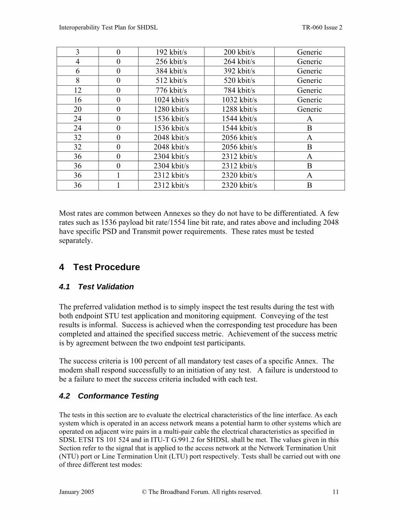
3.5 Test Bit Rates Table 2 identifies the bit rates to be tested in this test plan. All rates between and including the minimum and the maximum rates of Table 2 supported by the DUT shall be tested.
TABLE 2: BIT RATES
number of B-channels
number of Z-channels
payload bit rate resulting line bit rate Annex Type
Interoperability Test Plan for SHDSL TR-060 Issue 2
January 2005 © The Broadband Forum. All rights reserved. 11
3 0 192 kbit/s 200 kbit/s Generic 4 0 256 kbit/s 264 kbit/s Generic 6 0 384 kbit/s 392 kbit/s Generic 8 0 512 kbit/s 520 kbit/s Generic 12 0 776 kbit/s 784 kbit/s Generic 16 0 1024 kbit/s 1032 kbit/s Generic 20 0 1280 kbit/s 1288 kbit/s Generic 24 0 1536 kbit/s 1544 kbit/s A 24 0 1536 kbit/s 1544 kbit/s B 32 0 2048 kbit/s 2056 kbit/s A 32 0 2048 kbit/s 2056 kbit/s B 36 0 2304 kbit/s 2312 kbit/s A 36 0 2304 kbit/s 2312 kbit/s B 36 1 2312 kbit/s 2320 kbit/s A 36 1 2312 kbit/s 2320 kbit/s B
Most rates are common between Annexes so they do not have to be differentiated. A few rates such as 1536 payload bit rate/1554 line bit rate, and rates above and including 2048 have specific PSD and Transmit power requirements. These rates must be tested separately.
4 Test Procedure
4.1 Test Validation The preferred validation method is to simply inspect the test results during the test with both endpoint STU test application and monitoring equipment. Conveying of the test results is informal. Success is achieved when the corresponding test procedure has been completed and attained the specified success metric. Achievement of the success metric is by agreement between the two endpoint test participants. The success criteria is 100 percent of all mandatory test cases of a specific Annex. The modem shall respond successfully to an initiation of any test. A failure is understood to be a failure to meet the success criteria included with each test.
4.2 Conformance Testing The tests in this section are to evaluate the electrical characteristics of the line interface. As each system which is operated in an access network means a potential harm to other systems which are operated on adjacent wire pairs in a multi-pair cable the electrical characteristics as specified in SDSL ETSI TS 101 524 and in ITU-T G.991.2 for SHDSL shall be met. The values given in this Section refer to the signal that is applied to the access network at the Network Termination Unit (NTU) port or Line Termination Unit (LTU) port respectively. Tests shall be carried out with one of three different test modes:
Interoperability Test Plan for SHDSL TR-060 Issue 2
January 2005 © The Broadband Forum. All rights reserved. 12
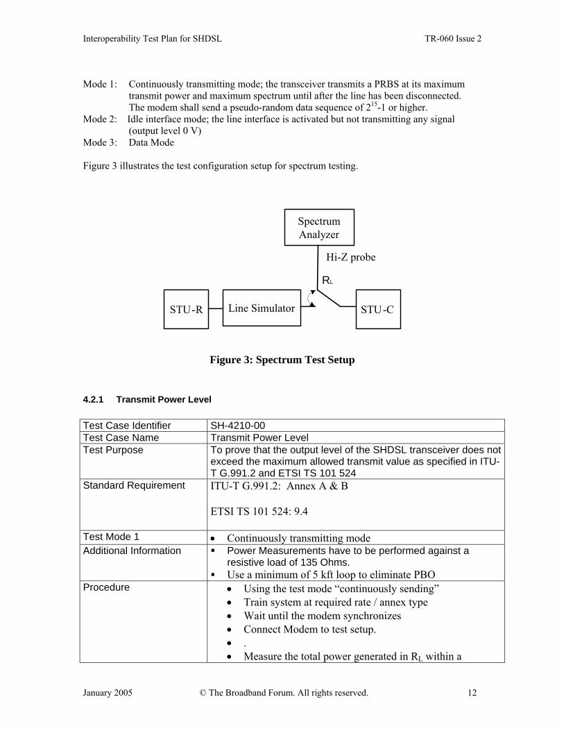
Mode 1: Continuously transmitting mode; the transceiver transmits a PRBS at its maximum
transmit power and maximum spectrum until after the line has been disconnected. The modem shall send a pseudo-random data sequence of 215-1 or higher.
Mode 2: Idle interface mode; the line interface is activated but not transmitting any signal (output level 0 V)
Mode 3: Data Mode
Figure 3 illustrates the test configuration setup for spectrum testing.
Line SimulatorSTU-R
SpectrumAnalyzer
STU-C
Hi-Z probe
RL
Figure 3: Spectrum Test Setup
4.2.1 Transmit Power Level Test Case Identifier SH-4210-00 Test Case Name Transmit Power Level Test Purpose To prove that the output level of the SHDSL transceiver does not
exceed the maximum allowed transmit value as specified in ITU-T G.991.2 and ETSI TS 101 524
Standard Requirement ITU-T G.991.2: Annex A & B ETSI TS 101 524: 9.4
Test Mode 1 • Continuously transmitting mode Additional Information Power Measurements have to be performed against a
resistive load of 135 Ohms. Use a minimum of 5 kft loop to eliminate PBO
Procedure • Using the test mode “continuously sending” • Train system at required rate / annex type • Wait until the modem synchronizes • Connect Modem to test setup. • . • Measure the total power generated in RL within a

Interoperability Test Plan for SHDSL TR-060 Issue 2
January 2005 © The Broadband Forum. All rights reserved. 13
frequency range at least covering the in-band SHDSL signal region.
Expected Results • Annex A & Annex B: Analog Front End transmit power shall be as defined in G.991.2..
4.2.2 Power Spectral Density (PSD) Tests Test Case Identifier SH-4220-00 Test Case Name Power Spectral Density Test Purpose To prove that the output spectrum of the SHDSL transceiver does not
exceed the maximum allowed PSD definition as specified in ITU-T G.991.2 and ETSI TS 101 524; and to test PSD to see if it meets mask after unit is completed
Standard Requirement ITU-T G.991.2: ETSI TS 101 524: 9.4
Test Mode 1 • Continuously transmitting mode Additional Information Power Measurements have to be performed against a
resistive load of 135 Ohms Use a minimum of 5 kft loop to eliminate PBO
Procedure • Using the test mode “continuously sending” • • Connect Modem to test setup. • Train system at required rate / annex type. • Measure the PSD generated in RL with a RBW = 10kHz
at frequency range from 1Hz to 1.5MHz Note: Large PSD variations over narrow frequency intervals (for example near the junction of the main lobe with the noise floor) might require a smaller resolution bandwidth (RBW) to be used. A good rule of thumb is to choose RBW such that there is no more than 1 dB change in the signal PSD across the RBW. It may be necessary to disregard spurious interference peaks observed when using narrow resolution bandwidths.
Expected Results Annex A & Annex B: PSD shall be within the limits of the PSD
Mask as per G.991.2 and ETSI TS 101 524
4.2.3 Power Back Off (PBO) Tests This test is to verify that the Power-Back-Off mechanism is working properly. STU-R and STU-C are connected at both sides of the SHDSL line simulator as depicted in Figure 3. The devices
Interoperability Test Plan for SHDSL TR-060 Issue 2
January 2005 © The Broadband Forum. All rights reserved. 14
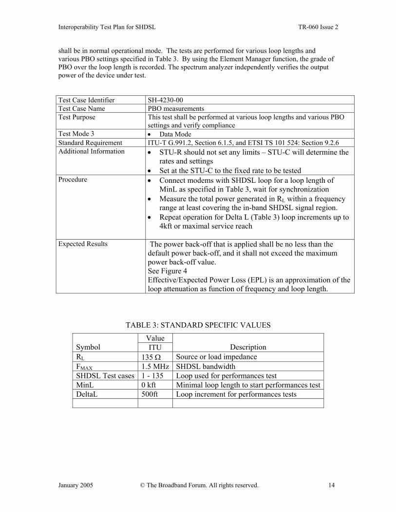
shall be in normal operational mode. The tests are performed for various loop lengths and various PBO settings specified in Table 3. By using the Element Manager function, the grade of PBO over the loop length is recorded. The spectrum analyzer independently verifies the output power of the device under test. Test Case Identifier SH-4230-00 Test Case Name PBO measurements Test Purpose This test shall be performed at various loop lengths and various PBO
settings and verify compliance Test Mode 3 • Data Mode Standard Requirement ITU-T G.991.2, Section 6.1.5, and ETSI TS 101 524: Section 9.2.6 Additional Information • STU-R should not set any limits – STU-C will determine the
rates and settings • Set at the STU-C to the fixed rate to be tested
Procedure • Connect modems with SHDSL loop for a loop length of MinL as specified in Table 3, wait for synchronization
• Measure the total power generated in RL within a frequency range at least covering the in-band SHDSL signal region.
• Repeat operation for Delta L (Table 3) loop increments up to 4kft or maximal service reach
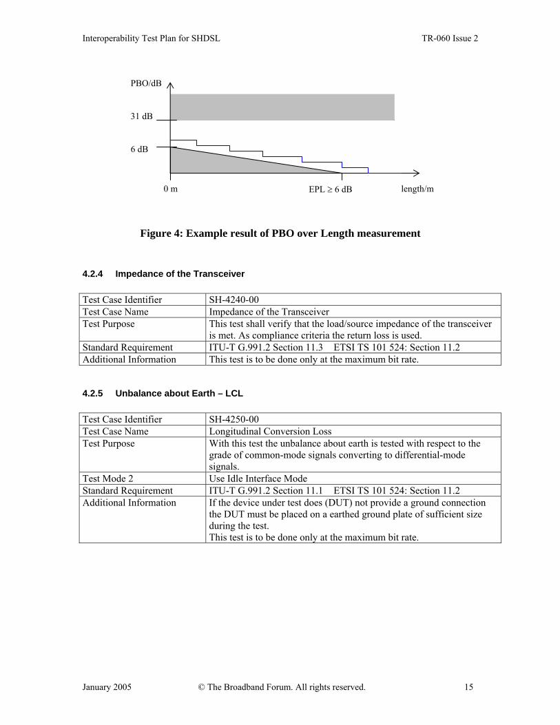
Expected Results The power back-off that is applied shall be no less than the
default power back-off, and it shall not exceed the maximum power back-off value. See Figure 4 Effective/Expected Power Loss (EPL) is an approximation of the loop attenuation as function of frequency and loop length.
TABLE 3: STANDARD SPECIFIC VALUES
Value Symbol ITU
Description
RL 135 Ω Source or load impedance FMAX 1.5 MHz SHDSL bandwidth SHDSL Test cases 1 - 135 Loop used for performances test MinL 0 kft Minimal loop length to start performances testDeltaL 500ft Loop increment for performances tests
Interoperability Test Plan for SHDSL TR-060 Issue 2
January 2005 © The Broadband Forum. All rights reserved. 15
Figure 4: Example result of PBO over Length measurement
4.2.4 Impedance of the Transceiver Test Case Identifier SH-4240-00 Test Case Name Impedance of the Transceiver Test Purpose This test shall verify that the load/source impedance of the transceiver
is met. As compliance criteria the return loss is used. Standard Requirement ITU-T G.991.2 Section 11.3 ETSI TS 101 524: Section 11.2 Additional Information This test is to be done only at the maximum bit rate.
4.2.5 Unbalance about Earth – LCL Test Case Identifier SH-4250-00 Test Case Name Longitudinal Conversion Loss Test Purpose With this test the unbalance about earth is tested with respect to the
grade of common-mode signals converting to differential-mode signals.
Test Mode 2 Use Idle Interface Mode Standard Requirement ITU-T G.991.2 Section 11.1 ETSI TS 101 524: Section 11.2 Additional Information If the device under test does (DUT) not provide a ground connection
the DUT must be placed on a earthed ground plate of sufficient size during the test. This test is to be done only at the maximum bit rate.
6 dB
31 dB
0 m EPL ≥ 6 dB
PBO/dB
length/m
Interoperability Test Plan for SHDSL TR-060 Issue 2
January 2005 © The Broadband Forum. All rights reserved. 16
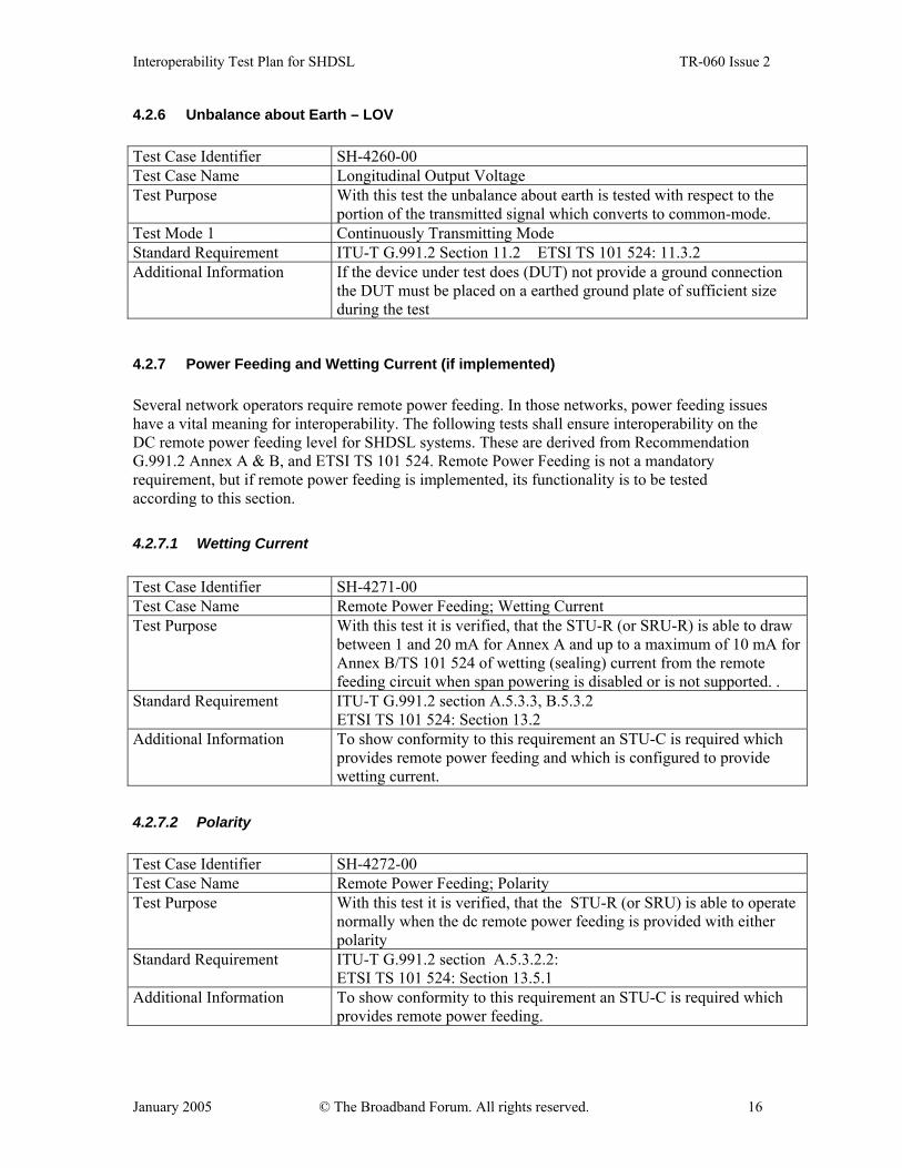
4.2.6 Unbalance about Earth – LOV Test Case Identifier SH-4260-00 Test Case Name Longitudinal Output Voltage Test Purpose With this test the unbalance about earth is tested with respect to the
portion of the transmitted signal which converts to common-mode. Test Mode 1 Continuously Transmitting Mode Standard Requirement ITU-T G.991.2 Section 11.2 ETSI TS 101 524: 11.3.2 Additional Information If the device under test does (DUT) not provide a ground connection
the DUT must be placed on a earthed ground plate of sufficient size during the test
4.2.7 Power Feeding and Wetting Current (if implemented) Several network operators require remote power feeding. In those networks, power feeding issues have a vital meaning for interoperability. The following tests shall ensure interoperability on the DC remote power feeding level for SHDSL systems. These are derived from Recommendation G.991.2 Annex A & B, and ETSI TS 101 524. Remote Power Feeding is not a mandatory requirement, but if remote power feeding is implemented, its functionality is to be tested according to this section. 4.2.7.1 Wetting Current Test Case Identifier SH-4271-00 Test Case Name Remote Power Feeding; Wetting Current Test Purpose With this test it is verified, that the STU-R (or SRU-R) is able to draw
between 1 and 20 mA for Annex A and up to a maximum of 10 mA for Annex B/TS 101 524 of wetting (sealing) current from the remote feeding circuit when span powering is disabled or is not supported. .
Standard Requirement ITU-T G.991.2 section A.5.3.3, B.5.3.2 ETSI TS 101 524: Section 13.2
Additional Information To show conformity to this requirement an STU-C is required which provides remote power feeding and which is configured to provide wetting current.
4.2.7.2 Polarity Test Case Identifier SH-4272-00 Test Case Name Remote Power Feeding; Polarity Test Purpose With this test it is verified, that the STU-R (or SRU) is able to operate
normally when the dc remote power feeding is provided with either polarity
Standard Requirement ITU-T G.991.2 section A.5.3.2.2: ETSI TS 101 524: Section 13.5.1
Additional Information To show conformity to this requirement an STU-C is required which provides remote power feeding.
Interoperability Test Plan for SHDSL TR-060 Issue 2
January 2005 © The Broadband Forum. All rights reserved. 17
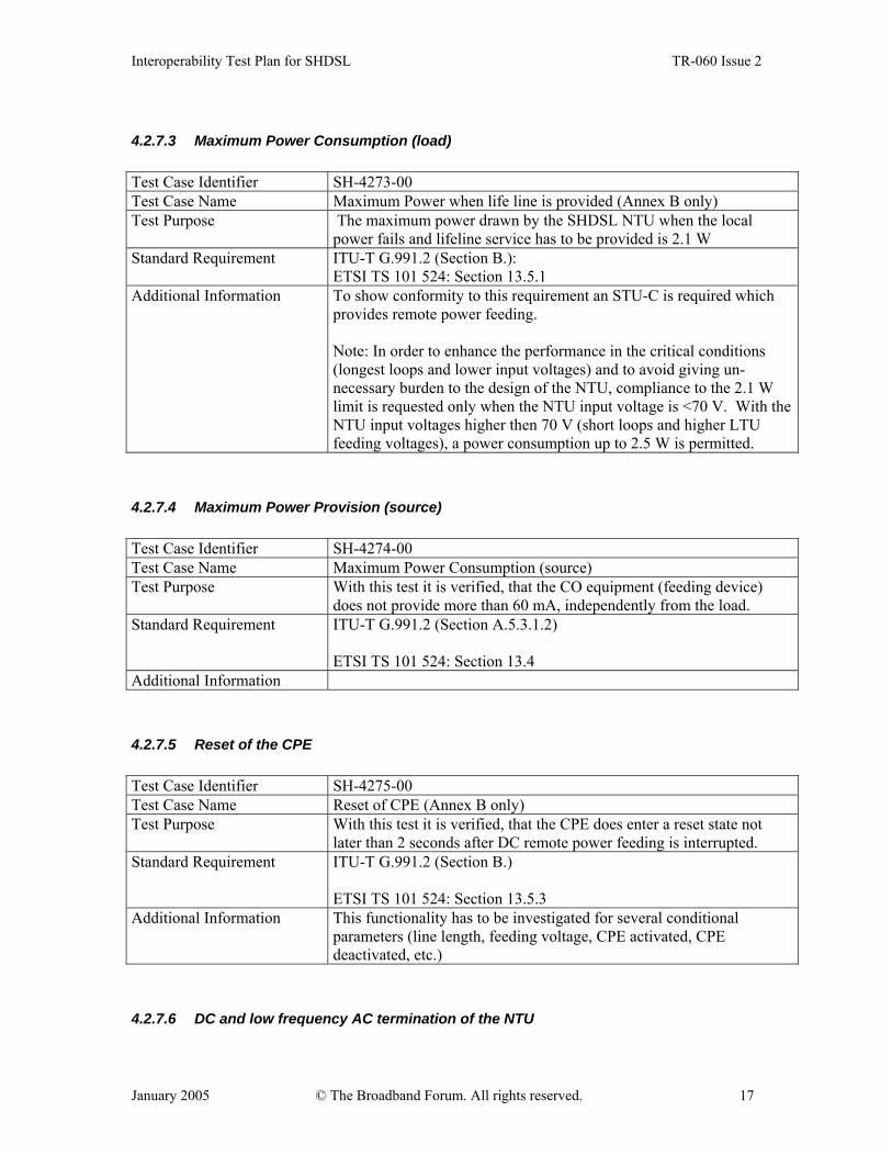
4.2.7.3 Maximum Power Consumption (load) Test Case Identifier SH-4273-00 Test Case Name Maximum Power when life line is provided (Annex B only) Test Purpose The maximum power drawn by the SHDSL NTU when the local
power fails and lifeline service has to be provided is 2.1 W Standard Requirement ITU-T G.991.2 (Section B.):
ETSI TS 101 524: Section 13.5.1 Additional Information To show conformity to this requirement an STU-C is required which
provides remote power feeding. Note: In order to enhance the performance in the critical conditions (longest loops and lower input voltages) and to avoid giving un-necessary burden to the design of the NTU, compliance to the 2.1 W limit is requested only when the NTU input voltage is <70 V. With the NTU input voltages higher then 70 V (short loops and higher LTU feeding voltages), a power consumption up to 2.5 W is permitted.
4.2.7.4 Maximum Power Provision (source) Test Case Identifier SH-4274-00 Test Case Name Maximum Power Consumption (source) Test Purpose With this test it is verified, that the CO equipment (feeding device)
does not provide more than 60 mA, independently from the load. Standard Requirement ITU-T G.991.2 (Section A.5.3.1.2)
ETSI TS 101 524: Section 13.4
Additional Information 4.2.7.5 Reset of the CPE Test Case Identifier SH-4275-00 Test Case Name Reset of CPE (Annex B only) Test Purpose With this test it is verified, that the CPE does enter a reset state not
later than 2 seconds after DC remote power feeding is interrupted. Standard Requirement ITU-T G.991.2 (Section B.)
ETSI TS 101 524: Section 13.5.3
Additional Information This functionality has to be investigated for several conditional parameters (line length, feeding voltage, CPE activated, CPE deactivated, etc.)
4.2.7.6 DC and low frequency AC termination of the NTU
Interoperability Test Plan for SHDSL TR-060 Issue 2
January 2005 © The Broadband Forum. All rights reserved. 18
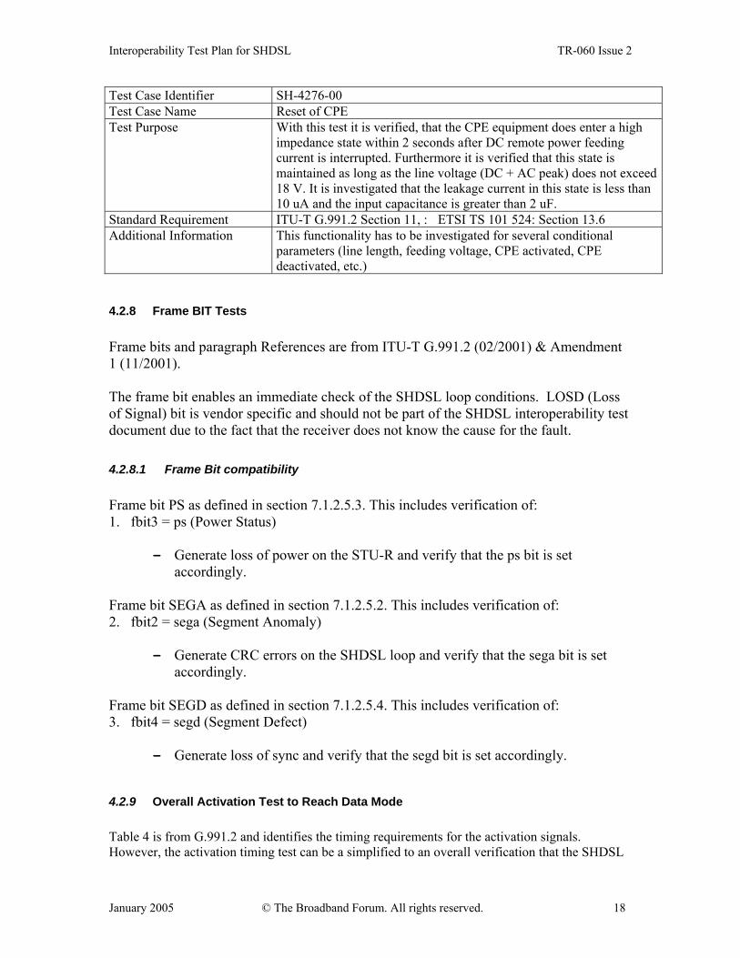
Test Case Identifier SH-4276-00 Test Case Name Reset of CPE Test Purpose With this test it is verified, that the CPE equipment does enter a high
impedance state within 2 seconds after DC remote power feeding current is interrupted. Furthermore it is verified that this state is maintained as long as the line voltage (DC + AC peak) does not exceed 18 V. It is investigated that the leakage current in this state is less than 10 uA and the input capacitance is greater than 2 uF.
Standard Requirement ITU-T G.991.2 Section 11, :ETSI TS 101 524: Section 13.6 Additional Information This functionality has to be investigated for several conditional
parameters (line length, feeding voltage, CPE activated, CPE deactivated, etc.)
4.2.8 Frame BIT Tests Frame bits and paragraph References are from ITU-T G.991.2 (02/2001) & Amendment 1 (11/2001). The frame bit enables an immediate check of the SHDSL loop conditions. LOSD (Loss of Signal) bit is vendor specific and should not be part of the SHDSL interoperability test document due to the fact that the receiver does not know the cause for the fault. 4.2.8.1 Frame Bit compatibility Frame bit PS as defined in section 7.1.2.5.3. This includes verification of: 1. fbit3 = ps (Power Status)
- Generate loss of power on the STU-R and verify that the ps bit is set accordingly.
Frame bit SEGA as defined in section 7.1.2.5.2. This includes verification of: 2. fbit2 = sega (Segment Anomaly)
- Generate CRC errors on the SHDSL loop and verify that the sega bit is set accordingly.
Frame bit SEGD as defined in section 7.1.2.5.4. This includes verification of: 3. fbit4 = segd (Segment Defect)
- Generate loss of sync and verify that the segd bit is set accordingly.
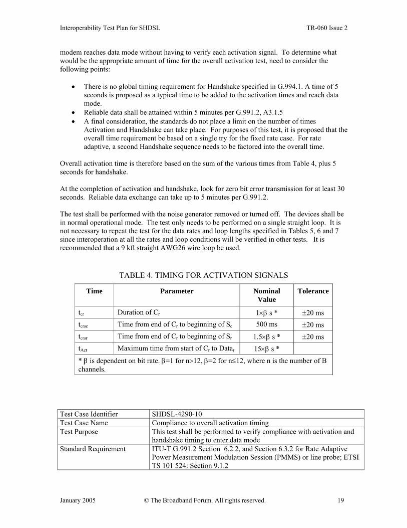
4.2.9 Overall Activation Test to Reach Data Mode Table 4 is from G.991.2 and identifies the timing requirements for the activation signals. However, the activation timing test can be a simplified to an overall verification that the SHDSL
Interoperability Test Plan for SHDSL TR-060 Issue 2
January 2005 © The Broadband Forum. All rights reserved. 19
modem reaches data mode without having to verify each activation signal. To determine what would be the appropriate amount of time for the overall activation test, need to consider the following points:
• There is no global timing requirement for Handshake specified in G.994.1. A time of 5 seconds is proposed as a typical time to be added to the activation times and reach data mode.
• Reliable data shall be attained within 5 minutes per G.991.2, A3.1.5 • A final consideration, the standards do not place a limit on the number of times
Activation and Handshake can take place. For purposes of this test, it is proposed that the overall time requirement be based on a single try for the fixed rate case. For rate adaptive, a second Handshake sequence needs to be factored into the overall time.
Overall activation time is therefore based on the sum of the various times from Table 4, plus 5 seconds for handshake. At the completion of activation and handshake, look for zero bit error transmission for at least 30 seconds. Reliable data exchange can take up to 5 minutes per G.991.2. The test shall be performed with the noise generator removed or turned off. The devices shall be in normal operational mode. The test only needs to be performed on a single straight loop. It is not necessary to repeat the test for the data rates and loop lengths specified in Tables 5, 6 and 7 since interoperation at all the rates and loop conditions will be verified in other tests. It is recommended that a 9 kft straight AWG26 wire loop be used.
TABLE 4. TIMING FOR ACTIVATION SIGNALS
Time Parameter Nominal Value
Tolerance
tcr Duration of Cr 1×β s * ±20 ms tcrsc Time from end of Cr to beginning of Sc 500 ms ±20 ms tcrsr Time from end of Cr to beginning of Sr 1.5×β s * ±20 ms tAct Maximum time from start of Cr to Datar 15×β s *
* β is dependent on bit rate. β=1 for n>12, β=2 for n≤12, where n is the number of B channels.
Test Case Identifier SHDSL-4290-10 Test Case Name Compliance to overall activation timing Test Purpose This test shall be performed to verify compliance with activation and
handshake timing to enter data mode Standard Requirement ITU-T G.991.2 Section 6.2.2, and Section 6.3.2 for Rate Adaptive
Power Measurement Modulation Session (PMMS) or line probe; ETSI TS 101 524: Section 9.1.2
Interoperability Test Plan for SHDSL TR-060 Issue 2
January 2005 © The Broadband Forum. All rights reserved. 20
Additional Information • STU-R should not set any limits – STU-C will determine the rates and settings
• Set at the STU-C to the fixed rate to be tested Procedure • Connect modems with 9 kft straight AWG26 loop with the
noise turned off.
Expected Results Fixed Rate: • N<= 12, reach data mode 35.5 seconds +/- 0.5s • N > 12, reach data mode in 23s +/- 0.5s Rate Adaptive (includes additional 5s for second HS and 10s for PMMS):
• N <= 12, reach data mode in 55.5s +/- 0.5s • N > 12, reach data mode in 38s +/- 0.5s
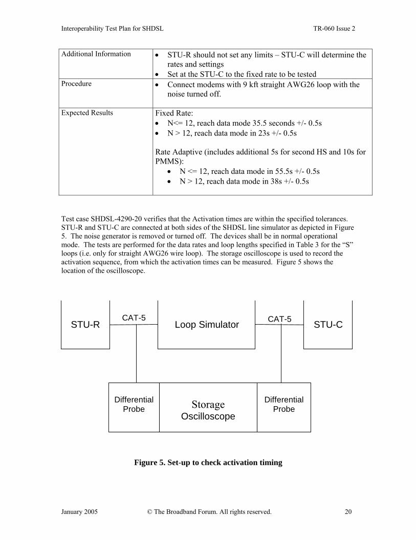
Test case SHDSL-4290-20 verifies that the Activation times are within the specified tolerances. STU-R and STU-C are connected at both sides of the SHDSL line simulator as depicted in Figure 5. The noise generator is removed or turned off. The devices shall be in normal operational mode. The tests are performed for the data rates and loop lengths specified in Table 3 for the “S” loops (i.e. only for straight AWG26 wire loop). The storage oscilloscope is used to record the activation sequence, from which the activation times can be measured. Figure 5 shows the location of the oscilloscope.
STU-R STU-C Loop Simulator CAT-5 CAT-5
Storage
Oscilloscope
Differential
Probe
Differential
Probe
Figure 5. Set-up to check activation timing
Interoperability Test Plan for SHDSL TR-060 Issue 2
January 2005 © The Broadband Forum. All rights reserved. 21
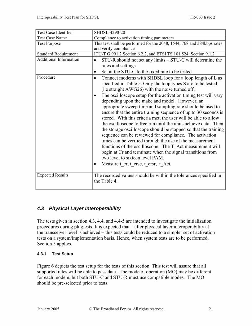
Test Case Identifier SHDSL-4290-20 Test Case Name Compliance to activation timing parameters Test Purpose This test shall be performed for the 2048, 1544, 768 and 384kbps rates
and verify compliance Standard Requirement ITU-T G.991.2 Section 6.2.2, and ETSI TS 101 524: Section 9.1.2 Additional Information • STU-R should not set any limits – STU-C will determine the
rates and settings • Set at the STU-C to the fixed rate to be tested
Procedure • Connect modems with SHDSL loop for a loop length of L as specified in Table 5. Only the loop types S are to be tested (i.e straight AWG26) with the noise turned off.
• The oscilloscope setup for the activation timing test will vary depending upon the make and model. However, an appropriate sweep time and sampling rate should be used to ensure that the entire training sequence of up to 30 seconds is stored. With this criteria met, the user will be able to allow the oscilloscope to free run until the units achieve data. Then the storage oscilloscope should be stopped so that the training sequence can be reviewed for compliance. The activation times can be verified through the use of the measurement functions of the oscilloscope. The T_Act measurement will begin at Cr and terminate when the signal transitions from two level to sixteen level PAM.
• Measure t_cr, t_crsc, t_crsr, t_Act.
Expected Results The recorded values should be within the tolerances specified in the Table 4.
4.3 Physical Layer Interoperability The tests given in section 4.3, 4.4, and 4.4-5 are intended to investigate the initialization procedures during plugfests. It is expected that – after physical layer interoperability at the transceiver level is achieved – this tests could be reduced to a simpler set of activation tests on a system/implementation basis. Hence, when system tests are to be performed, Section 5 applies.
4.3.1 Test Setup Figure 6 depicts the test setup for the tests of this section. This test will assure that all supported rates will be able to pass data. The mode of operation (MO) may be different for each modem, but both STU-C and STU-R must use compatible modes. The MO should be pre-selected prior to tests.

Interoperability Test Plan for SHDSL TR-060 Issue 2
January 2005 © The Broadband Forum. All rights reserved. 22
Mode of operations:
1. Clear channel Synchronous 2. Clear channel Plesiochronous 3. Fractional E1 Plesiochronous 4. Fractional T1 Plesiochronous 5. ATM Synchronous
Mode of operation to be tested will be determined per system.
STU-C Line Simulator STU-R
TrafficAnalyser
Figure 6: Test Setup
4.3.2 Activation– Short Loops 4.3.2.1 Zero Loop BER Data Transfer For this test the two systems are connected over a Zero-Loop. Criteria for passing this test is the achievement of steady transmission with a bit error rate BER < 10-7 over the Zero-Loop. As the test is done by using an IP connection (Layer 3 performance) bit error rate is calculated on IP packet basis. . A minimum of 108 bits should be passed for this test. Test Case Identifier SH-4321-00 Test Case Name Zero Loop BER Data Transfer Test Purpose With this test it is verified, that two systems do achieve steady
transmission state after a reasonable time when they are linked to each other over a Zero-Loop. Transmission quality is taken as pass/fail criteria. With this test it is proven, that systems do not enter a overload condition when they are used back-to-back.
Standard Requirement ITU-T G.991.2 (Section 6.1.5):ETSI TS 101 524: Section 12.3 Additional Information The test shall be performed at bit rates contained in Table 2. When
asymmetric PSD is supported, additional test with asymmetric PSD is to be performed.
Expected Results A minimum of 108 bits should be passed for this test with a bit error rate BER < 10-7
Interoperability Test Plan for SHDSL TR-060 Issue 2
January 2005 © The Broadband Forum. All rights reserved. 23
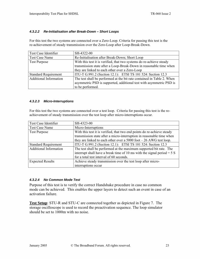
4.3.2.2 Re-Initialisation after Break-Down – Short Loops For this test the two systems are connected over a Zero-Loop. Criteria for passing this test is the re-achievement of steady transmission over the Zero-Loop after Loop-Break-Down. Test Case Identifier SH-4322-00 Test Case Name Re-Initialisation after Break-Down; Short Loop Test Purpose With this test it is verified, that two systems do re-achieve steady
transmission state after a Loop-Break-Down in reasonable time when they are linked to each other over a Zero-Loop
Standard Requirement ITU-T G.991.2 (Section 12.1):ETSI TS 101 524: Section 12.3 Additional Information The test shall be performed at the bit rate contained in Table 2. When
asymmetric PSD is supported, additional test with asymmetric PSD is to be performed.
4.3.2.3 Micro-Interruptions For this test the two systems are connected over a test loop. Criteria for passing this test is the re-achievement of steady transmission over the test loop after micro-interruptions occur. Test Case Identifier SH-4323-00 Test Case Name Micro-Interruptions Test Purpose With this test it is verified, that two end points do re-achieve steady
transmission state after a micro-interruption in reasonable time when they are linked to each other over a 5000 foot – 26 AWG test loop.
Standard Requirement ITU-T G.991.2 (Section 12.1):ETSI TS 101 524: Section 12.3 Additional Information The test shall be performed at the maximum supported bit rate. The
interrupt shall have a break time of 10 ms with the signal period = 5 S for a total test interval of 60 seconds.
Expected Results Achieve steady transmission over the test loop after micro-interruptions occur
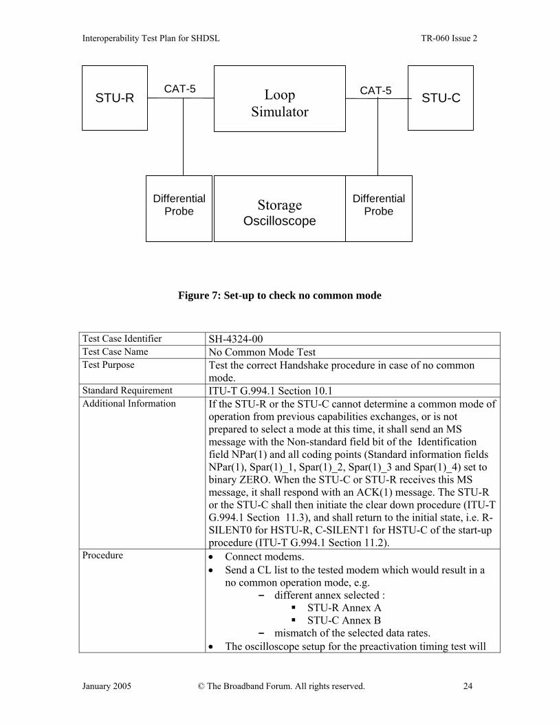
4.3.2.4 No Common Mode Test Purpose of this test is to verify the correct Handshake procedure in case no common mode can be achieved. This enables the upper layers to detect such an event in case of an activation failure. Test Setup: STU-R and STU-C are connected together as depicted in Figure 7. The storage oscilloscope is used to record the preactivation sequence. The loop simulator should be set to 1000m with no noise.
Interoperability Test Plan for SHDSL TR-060 Issue 2
January 2005 © The Broadband Forum. All rights reserved. 24
STU-R STU-CCAT-5 CAT-5
Storage
Oscilloscope
Differential
Probe
Differential
Probe
Loop
Simulator
Figure 7: Set-up to check no common mode
Test Case Identifier SH-4324-00 Test Case Name No Common Mode Test Test Purpose Test the correct Handshake procedure in case of no common
mode. Standard Requirement ITU-T G.994.1 Section 10.1 Additional Information If the STU-R or the STU-C cannot determine a common mode of
operation from previous capabilities exchanges, or is not prepared to select a mode at this time, it shall send an MS message with the Non-standard field bit of the Identification field NPar(1) and all coding points (Standard information fields NPar(1), Spar(1)_1, Spar(1)_2, Spar(1)_3 and Spar(1)_4) set to binary ZERO. When the STU-C or STU-R receives this MS message, it shall respond with an ACK(1) message. The STU-R or the STU-C shall then initiate the clear down procedure (ITU-T G.994.1 Section 11.3), and shall return to the initial state, i.e. R-SILENT0 for HSTU-R, C-SILENT1 for HSTU-C of the start-up procedure (ITU-T G.994.1 Section 11.2).
Procedure • Connect modems. • Send a CL list to the tested modem which would result in a
no common operation mode, e.g. - different annex selected :
STU-R Annex A STU-C Annex B
- mismatch of the selected data rates. • The oscilloscope setup for the preactivation timing test will
Interoperability Test Plan for SHDSL TR-060 Issue 2
January 2005 © The Broadband Forum. All rights reserved. 25
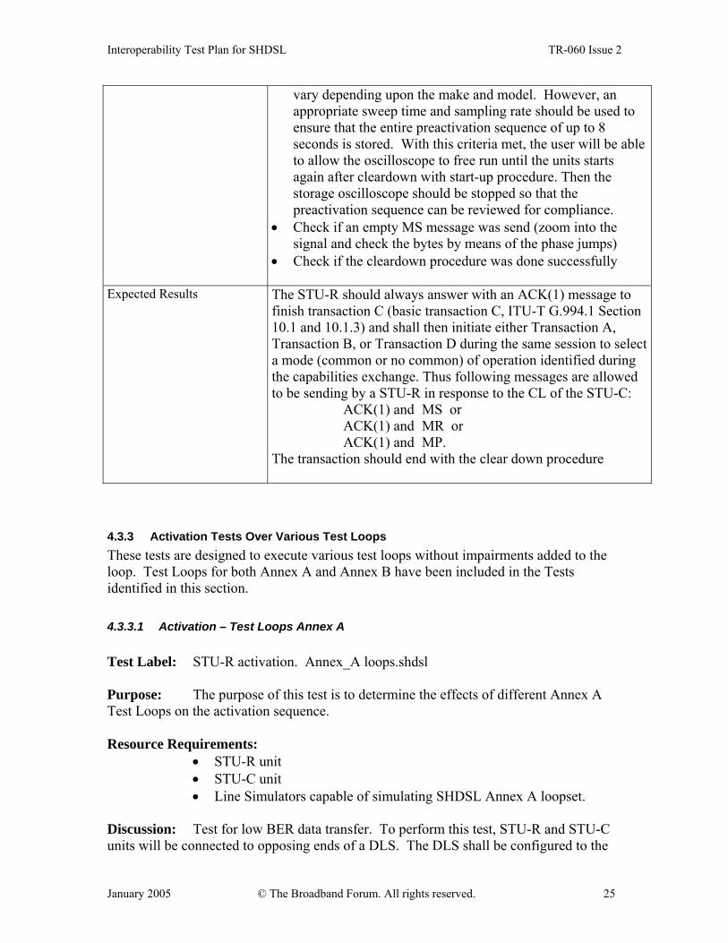
vary depending upon the make and model. However, an appropriate sweep time and sampling rate should be used to ensure that the entire preactivation sequence of up to 8 seconds is stored. With this criteria met, the user will be able to allow the oscilloscope to free run until the units starts again after cleardown with start-up procedure. Then the storage oscilloscope should be stopped so that the preactivation sequence can be reviewed for compliance.
• Check if an empty MS message was send (zoom into the signal and check the bytes by means of the phase jumps)
• Check if the cleardown procedure was done successfully
Expected Results The STU-R should always answer with an ACK(1) message to finish transaction C (basic transaction C, ITU-T G.994.1 Section 10.1 and 10.1.3) and shall then initiate either Transaction A, Transaction B, or Transaction D during the same session to select a mode (common or no common) of operation identified during the capabilities exchange. Thus following messages are allowed to be sending by a STU-R in response to the CL of the STU-C: ACK(1) and MS or ACK(1) and MR or ACK(1) and MP. The transaction should end with the clear down procedure
4.3.3 Activation Tests Over Various Test Loops These tests are designed to execute various test loops without impairments added to the loop. Test Loops for both Annex A and Annex B have been included in the Tests identified in this section. 4.3.3.1 Activation – Test Loops Annex A Test Label: STU-R activation. Annex_A loops.shdsl Purpose: The purpose of this test is to determine the effects of different Annex A Test Loops on the activation sequence. Resource Requirements:
• STU-R unit • STU-C unit • Line Simulators capable of simulating SHDSL Annex A loopset.
Discussion: Test for low BER data transfer. To perform this test, STU-R and STU-C units will be connected to opposing ends of a DLS. The DLS shall be configured to the

Interoperability Test Plan for SHDSL TR-060 Issue 2
January 2005 © The Broadband Forum. All rights reserved. 26
various Annex A test loops in Figure 8 and as specified in Tables 5 and 6. The test shall be executed without noise inserted into the loop by the DLS. Each DUT should successfully pass through the activation states specified in Figure 6.7 of the ITU-T G.991.2 Recommendation without entering the exception state. Both units should converge and be ready to pass data. Procedure:
• Configure the DLS to simulate the test Loop • Connect a STU-R and STU-C to opposite ends of the DLS. • Configure the DSL to provide noise free simulation over specified
loop. • STU-R should not set any limits – STU-C will determine the rates and
settings • Set at the STU-C to the fixed rate to be tested as per Tables 5 and 6 for
Annex A • Test for convergence
Test Case Identifier SH-4331-00 Test Case Name Activation – Test Loops Annex A Test Purpose Purpose is to determine the effects of different Annex A Test Loops on
the activation sequence Standard Requirement ITU-T G.991.2 (Section 6.2.2) – per states specified in Figure 6.7 Additional Information For test loops in Figure 8, conduct tests specified in Tables 5 and 6.
Expected Results Verify that device reaches convergence

Interoperability Test Plan for SHDSL TR-060 Issue 2
January 2005 © The Broadband Forum. All rights reserved. 27
STU-R STU-CL x 1000'
26 AWGLoop S
STU-R STU-CL x 1000'
26 AWGLoop BTI-C
800'24 AWG
STU-R STU-CL x 1000'
26 AWGLoop BTI-R
800'24 AWG
STU-R STU-CL x 1000'
26 AWGLoop BT2-C
1500'26 AWG
STU-R STU-CL x 1000'
26 AWGLoop BT2-R
1500'26 AWG
STU-R STU-CLoop C4
800'26 AWG
400'26 AWG
550'26 AWG
6250'26 AWG
800'26 AWG
NOTES:AWG = American Wire Guage; 26 AWG = 0.4 mm, 24 AWG = 0.5 mmDistances in Feet ('): 1000' = 0.3048 km
Figure 8: Test Loops for Annex A

Interoperability Test Plan for SHDSL TR-060 Issue 2
January 2005 © The Broadband Forum. All rights reserved. 28
TABLE 5: ITU-T G.991.2: ANNEX A – SYMMETRIC RATES
Test Test Loop
L (kft)
Test Unit
Payload Bit Rate (kbps)
Interferer Combination
9 S 6.3 STU-C 2 304 24-T1 + 24 SHDSL asym 1544 10 BT1-C 5.2 STU-C 2 304 24-T1 + 24 SHDSL asym 1544 11 BT1-C 5.2 STU-C 2 304 49-SHDSL 12 S 6.3 STU-R 2 304 49-SHDSL 13 BT1-R 5.2 STU-R 2 304 49-SHDSL 14 BT1-R 5.2 STU-R 2 304 24-T1 + 24 SHDSL asym 1544 15 S 6.8 STU-C 2 048 24-SHDSL + 24-FDD ADSL 16 BT1-C 5.6 STU-C 2 048 49-SHDSL 17 BT1-C 5.6 STU-C 2 048 24-T1 + 24 SHDSL asym 1544 18 S 6.8 STU-R 2 048 49-SHDSL 19 BT1-R 5.6 STU-R 2 048 49-SHDSL 20 BT1-R 5.6 STU-R 2 048 24-T1 + 24 SHDSL asym 1544 21 S 7.9 STU-C 1 544 39-SHDSL asym 1544 22 BT1-C 6.4 STU-C 1 544 24-FDD ADSL + 24 SHDSL asym 1544 23 BT1-C 6.4 STU-C 1 544 24-SHDSL + 24-FDD ADSL 24 S 7.9 STU-R 1 544 49-SHDSL 25 BT1-R 6.4 STU-R 1 544 24-T1 + 24 SHDSL asym 1544 26 BT1-R 6.4 STU-R 1 544 49-SHDSL
27/30 S 11.0 STU-C/R 768 49-HDSL 28/31 BT1-C 10.2 STU-C/R 768 49-SHDSL 29/32 BT1-C 10.2 STU-C/R 768 49-HDSL 39/42 S 14.8 STU-C/R 384 24-SHDSL + 24-DSL 40/43 BT2-C 13.8 STU-C/R 384 24-SHDSL + 24-DSL 41/44 BT2-C 13.8 STU-C/R 384 49-SHDSL 45/48 S 17.2 STU-C/R 256 49-DSL 46/49 BT2-C 16.4 STU-C/R 256 49-DSL 47/50 BT2-C 16.4 STU-C/R 256 24-SHDSL + 24-DSL 51/54 S 19.8 STU-C/R 192 49-DSL 52/55 BT2-C 19.1 STU-C/R 192 49-DSL 53/56 BT2-C 19.1 STU-C/R 192 24-DSL + 24 SHDSL

Interoperability Test Plan for SHDSL TR-060 Issue 2
January 2005 © The Broadband Forum. All rights reserved. 29
TABLE 6: ITU-T G.991.2: ANNEX A – ASYMMETRIC RATES
Test Test Loop
L (kft)
Test Unit
Payload Bit Rate (kbps)
Interferer Combination
1 / 7 C4 - STU-C /R 1544 24T1 + 24 SHDSL 2 C4 - STU-C 1544 39 SHDSL 3 C4 - STU-C 1544 24 FDD ADSL + 24 HDSL
4 / 8 S 9.0 STU-C/ R 1544 24T1 + 24 SHDSL 5 S 9.0 STU-C 1544 39 SHDSL 6 S 9.0 STU-C 1544 24 FDD ADSL + 24 HDSL
33 S 11.2 STU-C 768 49-HDSL 34 BT1-C 10.4 STU-C 768 49-HDSL 35 BT1-C 10.4 STU-C 768 24-FDD ADSL+24-HDSL 36 S 11.2 STU-R 768 24-T1+24 HDSL 37 BT1-R 10.4 STU-R 768 24-T1+24-SHDSL 38 BT1-R 10.4 STU-R 768 39-FDD ADSL
4.3.3.2 Activation – Test Loops Annex B Test Label: STU-R activation. Annex_B loops.shdsl Purpose: The purpose of this test is to determine the effects of different Annex B Test Loops on the activation sequence. Resource Requirements:
• STU-R unit • STU-C unit • Line Simulators capable of simulating SHDSL Annex B loopset.
Discussion: Test for error-free data transfer. To perform this test, STU-R and STU-C units will be connected to opposing ends of a DLS. The DLS shall be configured to the various Annex B test loops in Figure 9 and as specified in Tables 7-10. The test shall be executed without noise inserted into the loop by the DLS. Each DUT should successfully pass through the activation states specified in Fig 6.7 of the ITU-T G.991.2 Recommendation without entering the exception state. Both units should converge and be ready to pass data. Note: DLS global change Procedure:
• Configure the DLS to simulate the test Loop

Interoperability Test Plan for SHDSL TR-060 Issue 2
January 2005 © The Broadband Forum. All rights reserved. 30
• Connect a STU-R and STU-C to opposite ends of the DLS. • Configure the DSL to provide noise free simulation over specified
loop. • STU-R should not set any limits – STU-C will determine the rates and
settings • Set at the STU-C to the fixed rate to be tested as per Table 7-10 for
Annex B • Test for convergence

Interoperability Test Plan for SHDSL TR-060 Issue 2
January 2005 © The Broadband Forum. All rights reserved. 31
T1541530-00(114701)
300 m
(PVC063)
(~0.20*Y dB)
(PE05)
(~0.60*Y dB)
(PE04) (PVC032)
0.2866*L4(~0.25*Y dB)
(PE06)
0.3668*L4(~0.50*Y dB)
(PE04) (PE05)
STU-C
STU-C
STU-R STU-C
STU-R STU-C
STU-R STU-C
L2(Y dB)STU-R STU-C
STU-R
0 dB
0.1834*L3(~0.25*Y dB)
(PE04)
0.2866*L3(~0.25*Y dB)
(PE06)
0.3466*L3(~0.25*Y dB)
(PE05)
0.1834*L3(~0.25*Y dB)
(PE04)
0.3466*L4(~0.25*Y dB)
100 m(~0.10*Y dB)
(PVC04)
L5 - 200 m(~0.80*Y dB)
(PE08) (PVC04)
100 m(~0.10*Y dB)
0.2857*L6(~0.20*Y dB)
(PE04)
0.7143*L6(~0.60*Y dB)
(PE04)
50 m
STU-C
67 Ω 159 Ω 120 Ω 75 Ω
0.3865*(L7-350m) 0.6135*(L7-350m)
120 Ω 120 Ω
73 Ω 124 Ω 73 Ω
106 Ω 120 Ω 159 Ω
120 Ω 106 Ω 120 Ω159 Ω
120 Ω(PE04)
STU-R
STU-R
LOOP #4
LOOP #5
LOOP #2
LOOP #3
BridgeTap500 m(PE04)
BridgeTap500 m(PE04)
LOOP #6
LOOP #7
LOOP #1
NOTE 1 - The values for Y and L are to be found in Table B-1.NOTE 2 - Due to mismatches and bridged taps the total attenuation of the test loops differs from the sum of the attenuation of the parts.NOTE 3 - The impedances are for information only. They refer to the characteristic impedances of the test cables as defined in Appendix II measured at 300 kHz.
Figure 9: ITU-T G.991.2: Annex B; ETSI TS101 524: Section 12.3
Interoperability Test Plan for SHDSL TR-060 Issue 2
January 2005 © The Broadband Forum. All rights reserved. 32
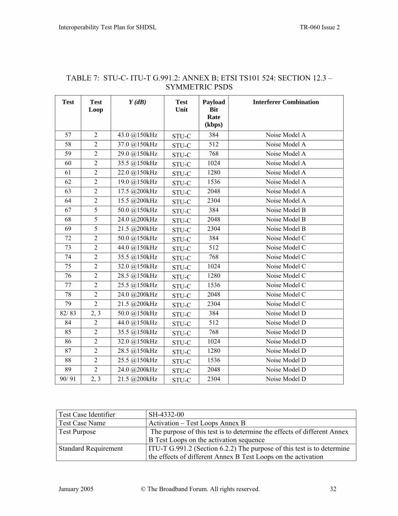
TABLE 7: STU-C- ITU-T G.991.2: ANNEX B; ETSI TS101 524: SECTION 12.3 – SYMMETRIC PSDS
Test Test Loop
Y (dB) Test Unit
PayloadBit
Rate (kbps)
Interferer Combination
57 2 43.0 @150kHz STU-C 384 Noise Model A 58 2 37.0 @150kHz STU-C 512 Noise Model A 59 2 29.0 @150kHz STU-C 768 Noise Model A 60 2 35.5 @150kHz STU-C 1024 Noise Model A 61 2 22.0 @150kHz STU-C 1280 Noise Model A 62 2 19.0 @150kHz STU-C 1536 Noise Model A 63 2 17.5 @200kHz STU-C 2048 Noise Model A 64 2 15.5 @200kHz STU-C 2304 Noise Model A 67 5 50.0 @150kHz STU-C 384 Noise Model B 68 5 24.0 @200kHz STU-C 2048 Noise Model B 69 5 21.5 @200kHz STU-C 2304 Noise Model B 72 2 50.0 @150kHz STU-C 384 Noise Model C 73 2 44.0 @150kHz STU-C 512 Noise Model C 74 2 35.5 @150kHz STU-C 768 Noise Model C 75 2 32.0 @150kHz STU-C 1024 Noise Model C 76 2 28.5 @150kHz STU-C 1280 Noise Model C 77 2 25.5 @150kHz STU-C 1536 Noise Model C 78 2 24.0 @200kHz STU-C 2048 Noise Model C 79 2 21.5 @200kHz STU-C 2304 Noise Model C
82/ 83 2, 3 50.0 @150kHz STU-C 384 Noise Model D 84 2 44.0 @150kHz STU-C 512 Noise Model D 85 2 35.5 @150kHz STU-C 768 Noise Model D 86 2 32.0 @150kHz STU-C 1024 Noise Model D 87 2 28.5 @150kHz STU-C 1280 Noise Model D 88 2 25.5 @150kHz STU-C 1536 Noise Model D 89 2 24.0 @200kHz STU-C 2048 Noise Model D
90/ 91 2, 3 21.5 @200kHz STU-C 2304 Noise Model D Test Case Identifier SH-4332-00 Test Case Name Activation – Test Loops Annex B Test Purpose The purpose of this test is to determine the effects of different Annex
B Test Loops on the activation sequence Standard Requirement ITU-T G.991.2 (Section 6.2.2) The purpose of this test is to determine
the effects of different Annex B Test Loops on the activation

Interoperability Test Plan for SHDSL TR-060 Issue 2
January 2005 © The Broadband Forum. All rights reserved. 33
sequence:ETSI TS 101 524: Section 12.3 ? Additional Information • For test loops in Figure 8, conduct tests specified in Tables 7 - 10.
Expected Results Verify that device reaches convergence
TABLE 8: STU-C- ITU-T G.991.2: ANNEX B; ETSI TS 101 524: SECTION 12.3 – ASYMMETRIC PSDS
Test Test Loop
Y (dB) Test Unit
PayloadBit
Rate (kbps)
Interferer Combination
65 2 17.5 @200kHz STU-C 2048 Noise Model A 66 2 15.5 @200kHz STU-C 2304 Noise Model A 70 5 24.0 @200kHz STU-C 2048 Noise Model B 71 5 21.5 @200kHz STU-C 2304 Noise Model B 80 2 24.0 @200kHz STU-C 2048 Noise Model C 81 2 21.5 @200kHz STU-C 2304 Noise Model C
92/ 93 2, 3 24.0 @200kHz STU-C 2048 Noise Model D 94/ 95 2, 3 21.5 @200kHz STU-C 2304 Noise Model D
TABLE 9: STU-R- ITU-T G.991.2: ANNEX B; ETSI TS 101 524: SECTION 12.3 – SYMMETRIC PSDS
Test Test Loop
Y (dB) Test Unit
Payload Bit Rate (kbps)
Interferer Combination
96 / 97/ 98 4, 6, 7 43.0 @150kHz STU-R 384 Noise Model A 99/ 100/ 101 4, 6, 7 17.5 @200kHz STU-R 2048 Noise Model A 102/ 103/ 104 4, 6, 7 15.5 @200kHz STU-R 2304 Noise Model A
111 7 50.0 @150kHz STU-R 384 Noise Model B 112 7 24.0 @200kHz STU-R 2048 Noise Model B 113 7 21.5 @200kHz STU-R 2304 Noise Model B
116/ 117/ 118 4, 6, 7 50.0 @150kHz STU-R 384 Noise Model C 119/ 120/ 121 4, 6, 7 24.0 @200kHz STU-R 2048 Noise Model C 122/ 123/ 124 4, 6, 7 21.5 @200kHz STU-R 2304 Noise Model C
131 7 50.0 @150kHz STU-R 384 Noise Model D 132 7 24.0 @200kHz STU-R 2048 Noise Model D 133 7 21.5 @200kHz STU-R 2304 Noise Model D
Interoperability Test Plan for SHDSL TR-060 Issue 2
January 2005 © The Broadband Forum. All rights reserved. 34
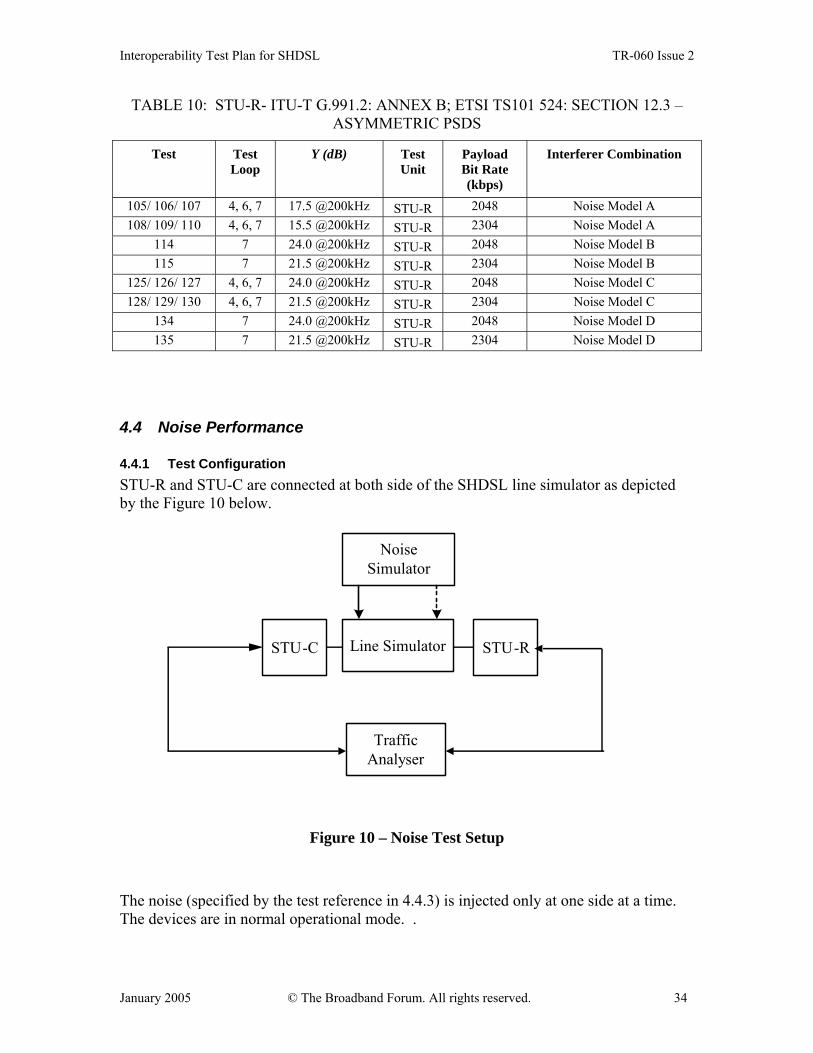
TABLE 10: STU-R- ITU-T G.991.2: ANNEX B; ETSI TS101 524: SECTION 12.3 – ASYMMETRIC PSDS
Test Test Loop
Y (dB) Test Unit
Payload Bit Rate (kbps)
Interferer Combination
105/ 106/ 107 4, 6, 7 17.5 @200kHz STU-R 2048 Noise Model A 108/ 109/ 110 4, 6, 7 15.5 @200kHz STU-R 2304 Noise Model A
114 7 24.0 @200kHz STU-R 2048 Noise Model B 115 7 21.5 @200kHz STU-R 2304 Noise Model B
125/ 126/ 127 4, 6, 7 24.0 @200kHz STU-R 2048 Noise Model C 128/ 129/ 130 4, 6, 7 21.5 @200kHz STU-R 2304 Noise Model C
134 7 24.0 @200kHz STU-R 2048 Noise Model D 135 7 21.5 @200kHz STU-R 2304 Noise Model D
4.4 Noise Performance
4.4.1 Test Configuration STU-R and STU-C are connected at both side of the SHDSL line simulator as depicted by the Figure 10 below.
STU-C Line Simulator STU-R
TrafficAnalyser
NoiseSimulator
Figure 10 – Noise Test Setup The noise (specified by the test reference in 4.4.3) is injected only at one side at a time. The devices are in normal operational mode. .
Interoperability Test Plan for SHDSL TR-060 Issue 2
January 2005 © The Broadband Forum. All rights reserved. 35
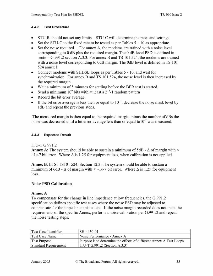
4.4.2 Test Procedure • STU-R should not set any limits – STU-C will determine the rates and settings • Set the STU-C to the fixed rate to be tested as per Tables 5 – 10 as appropriate • Set the noise required. . For annex A, the modems are trained with a noise level
corresponding to 0 dB plus the required margin. The 0 dB level PSD is defined in section G.991.2 section A.3.3. For annex B and TS 101 524, the modems are trained with a noise level corresponding to 0dB margin. The 0dB level is defined in TS 101 524 annex I.
• Connect modems with SHDSL loops as per Tables 5 - 10, and wait for synchronization. For annex B and TS 101 524, the noise level is then increased by the required margin.
• Wait a minimum of 5 minutes for settling before the BER test is started. • Send a minimum 109 bits with at least a 215-1 random pattern • Record the bit error average. • If the bit error average is less then or equal to 10–7, decrease the noise mask level by
1dB and repeat the previous steps. The measured margin is then equal to the required margin minus the number of dBs the noise was decreased until a bit error average less than or equal to10-7 was measured.
4.4.3 Expected Result ITU-T G.991.2 Annex A: The system should be able to sustain a minimum of 5dB - ∆ of margin with < ~1e-7 bit error. Where ∆ is 1.25 for equipment loss, when calibration is not applied. Annex B: ETSI TS101 524: Section 12.3: The system should be able to sustain a minimum of 6dB - ∆ of margin with < ~1e-7 bit error. Where ∆ is 1.25 for equipment loss. Noise PSD Calibration Annex A To compensate for the change in line impedance at low frequencies, the G.991.2 specification defines specific test cases where the noise PSD may be adjusted to compensate for the impedance mismatch. If the noise margin recorded does not meet the requirements of the specific Annex, perform a noise calibration per G.991.2 and repeat the noise testing steps. Test Case Identifier SH-4430-01 Test Case Name Noise Performance - Annex A Test Purpose Purpose is to determine the effects of different Annex A Test Loops Standard Requirement ITU-T G.991.2 (Section A.3.3)
Interoperability Test Plan for SHDSL TR-060 Issue 2
January 2005 © The Broadband Forum. All rights reserved. 36
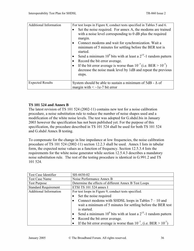
Additional Information For test loops in Figure 8, conduct tests specified in Tables 5 and 6. • Set the noise required. For annex A, the modems are trained
with a noise level corresponding to 0 dB plus the required margin.
• Connect modems and wait for synchronization. Wait a minimum of 5 minutes for settling before the BER test is started.
• Send a minimum 109 bits with at least a 215-1 random pattern • Record the bit error average. • If the bit error average is worse than 10–7 (i.e. BER > 10-7)
decrease the noise mask level by 1dB and repeat the previous steps.
Expected Results System should be able to sustain a minimum of 5dB - ∆ of
margin with < ~1e-7 bit error
TS 101 524 and Annex B The latest revision of TS 101 524 (2002-11) contains new test for a noise calibration procedure, a noise substitution rule to reduce the number of noise shapes used and a modification of the white noise levels. The test was adopted for G.shdsl.bis in January 2003 however the specification has not been published yet. For the purpose of this specification, the procedure described in TS 101 524 shall be used for both TS 101 524 and G.shdsl Annex B testing. To compensate for the change in line impedance at low frequencies, the noise calibration procedure of TS 101 524 (2002-11) section 12.2.3 shall be used. Annex I lists in tabular form, the expected noise values as a function of frequency. Section 12.5.3.4 lists the requirements for the white noise generator while section 12.5.4.3 describes a mandatory noise substitution rule. The rest of the testing procedure is identical in G.991.2 and TS 101 524. Test Case Identifier SH-4430-02 Test Case Name Noise Performance Annex B Test Purpose Determine the effects of different Annex B Test Loops Standard Requirement ETSI TS 101 524 annex I Additional Information For test loops in Figure 9, conduct tests specified.
• Set the noise required • Connect modems with SHDSL loops in Tables 7 – 10 and
wait a minimum of 5 minutes for settling before the BER test is started.
• Send a minimum 109 bits with at least a 215-1 random pattern • Record the bit error average. • If the bit error average is worse than 10–7, (i.e. BER > 10-7)
Interoperability Test Plan for SHDSL TR-060 Issue 2
January 2005 © The Broadband Forum. All rights reserved. 37
decrease the noise mask level by 1dB and repeat the previous steps.
Expected Results System should be able to sustain a minimum of 6dB - ∆ of
margin with < ~1e-7 bit error.
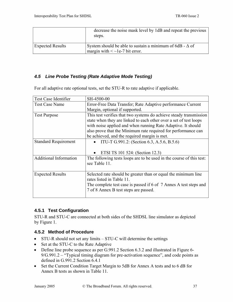
4.5 Line Probe Testing (Rate Adaptive Mode Testing) For all adaptive rate optional tests, set the STU-R to rate adaptive if applicable. Test Case Identifier SH-4500-00 Test Case Name Error-Free Data Transfer; Rate Adaptive performance Current
Margin, optional if supported. Test Purpose This test verifies that two systems do achieve steady transmission
state when they are linked to each other over a set of test loops with noise applied and when running Rate Adaptive. It should also prove that the Minimum rate required for performance can be achieved, and the required margin is met.
Standard Requirement • ITU-T G.991.2: (Section 6.3, A.5.6, B.5.6)
• ETSI TS 101 524: (Section 12.3) Additional Information The following tests loops are to be used in the course of this test:
see Table 11.
Expected Results Selected rate should be greater than or equal the minimum line rates listed in Table 11. The complete test case is passed if 6 of 7 Annes A test steps and 7 of 8 Annex B test steps are passed.
4.5.1 Test Configuration STU-R and STU-C are connected at both sides of the SHDSL line simulator as depicted by Figure 1.
4.5.2 Method of Procedure • STU-R should not set any limits – STU-C will determine the settings • Set at the STU-C to the Rate Adaptive • Define line probe sequence as per G.991.2 Section 6.3.2 and illustrated in Figure 6-
9/G.991.2 – “Typical timing diagram for pre-activation sequence”, and code points as defined in G.991.2 Section 6.4.1
• Set the Current Condition Target Margin to 5dB for Annex A tests and to 6 dB for Annex B tests as shown in Table 11.
Interoperability Test Plan for SHDSL TR-060 Issue 2
January 2005 © The Broadband Forum. All rights reserved. 38
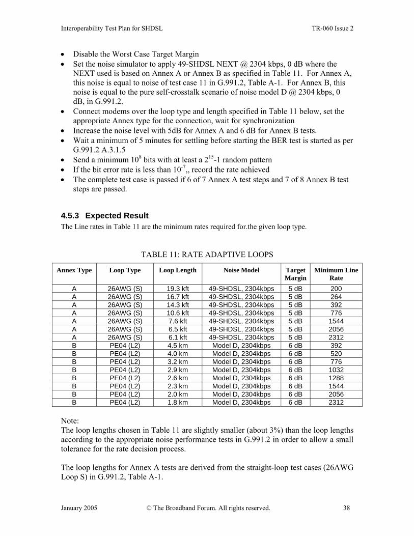
• Disable the Worst Case Target Margin • Set the noise simulator to apply 49-SHDSL NEXT @ 2304 kbps, 0 dB where the
NEXT used is based on Annex A or Annex B as specified in Table 11. For Annex A, this noise is equal to noise of test case 11 in G.991.2, Table A-1. For Annex B, this noise is equal to the pure self-crosstalk scenario of noise model D @ 2304 kbps, 0 dB, in G.991.2.
• Connect modems over the loop type and length specified in Table 11 below, set the appropriate Annex type for the connection, wait for synchronization
• Increase the noise level with 5dB for Annex A and 6 dB for Annex B tests. • Wait a minimum of 5 minutes for settling before starting the BER test is started as per
G.991.2 A.3.1.5 • Send a minimum 108 bits with at least a 215-1 random pattern • If the bit error rate is less than 10-7,, record the rate achieved • The complete test case is passed if 6 of 7 Annex A test steps and 7 of 8 Annex B test
steps are passed.
4.5.3 Expected Result The Line rates in Table 11 are the minimum rates required for.the given loop type.
TABLE 11: RATE ADAPTIVE LOOPS
Annex Type Loop Type
Loop Length Noise Model Target Margin
Minimum Line Rate
A 26AWG (S) 19.3 kft 49-SHDSL, 2304kbps 5 dB 200 A 26AWG (S) 16.7 kft 49-SHDSL, 2304kbps 5 dB 264 A 26AWG (S) 14.3 kft 49-SHDSL, 2304kbps 5 dB 392 A 26AWG (S) 10.6 kft 49-SHDSL, 2304kbps 5 dB 776 A 26AWG (S) 7.6 kft 49-SHDSL, 2304kbps 5 dB 1544 A 26AWG (S) 6.5 kft 49-SHDSL, 2304kbps 5 dB 2056 A 26AWG (S) 6.1 kft 49-SHDSL, 2304kbps 5 dB 2312 B PE04 (L2) 4.5 km Model D, 2304kbps 6 dB 392 B PE04 (L2) 4.0 km Model D, 2304kbps 6 dB 520 B PE04 (L2) 3.2 km Model D, 2304kbps 6 dB 776 B PE04 (L2) 2.9 km Model D, 2304kbps 6 dB 1032 B PE04 (L2) 2.6 km Model D, 2304kbps 6 dB 1288 B PE04 (L2) 2.3 km Model D, 2304kbps 6 dB 1544 B PE04 (L2) 2.0 km Model D, 2304kbps 6 dB 2056 B PE04 (L2) 1.8 km Model D, 2304kbps 6 dB 2312
Note: The loop lengths chosen in Table 11 are slightly smaller (about 3%) than the loop lengths according to the appropriate noise performance tests in G.991.2 in order to allow a small tolerance for the rate decision process. The loop lengths for Annex A tests are derived from the straight-loop test cases (26AWG Loop S) in G.991.2, Table A-1.

Interoperability Test Plan for SHDSL TR-060 Issue 2
January 2005 © The Broadband Forum. All rights reserved. 39
The loop lengths for Annex B tests are derived from straight-loop test cases (PE04 L2), Noise Model D, in G.991.2, Table B-2.
4.5.4 Test Configuration STU-R and STU-C are connected at both sides of the SHDSL line simulator as depicted by Figure 1. Test Case Identifier SH-4540-00 Test Case Name Functional Test; Rate Adaptive, Worst Case Margin, optional if
supported. Test Purpose This test verifies that two systems do achieve steady transmission
state when they are linked to each other over a set of test loops and when running Rate Adaptive Worst Case Margin. This would prove that the worst case margin would be functional.
Standard Requirement • ITU-T G.991.2 (Sections 6.3 and 6.4)
• ETSI TS 101 524: Section 12.3 Additional Information The following tests loops are to be used in the course of this test:
see Table12.
Expected Results
Selected rate should be within the minimum and maximum line rates listed in Table 12. The complete test case is passed if 6 of 7 Annex A test steps and 7 of 8 Annex B test steps are passed.
4.5.5 Method of Procedure • STU-R should not set any limits – STU-C will determine the settings • Set at the STU-C to the Rate Adaptive • Define line probe sequence as per G.991.2 Section 6.3.2 and illustrated in Figure 6-
9/G.991.2 – “Typical timing diagram for pre-activation sequence”, and code points as defined in G.991.2 Section 6.4.1
• Disable the Current Condition Margin • Set the Worst Case Margin to 5dB for Annex A tests and to 6 dB for the Annex B
tests as shown in Table 12. • Set the noise simulator to apply white noise at -140 dBm/Hz.
Note: This means that almost noise free environment is used for these tests. This is due to the fact that the test should verify if the rate is selected according to pre-measured reference worst case noise instead of current condition noise on the line. Worst case reference noises for PMMS are defined in ITU-T G.991.2, A.5.6 and Table A-13 for Annex A, and B.5.6 and Table B-14 for Annex B. Worst case noise is 49-SHDSL NEXT disturbers for both, Annex A and Annex B.
• Connect modems over the loop type and length specified in Table 12 below, set the appropriate Annex type for the connection, wait for synchronization

Interoperability Test Plan for SHDSL TR-060 Issue 2
January 2005 © The Broadband Forum. All rights reserved. 40
• Wait a minimum of 5 minutes for settling before starting the BER test. • Send a minimum 108 bits with at least a 215-1 random pattern • If the bit error rate is less than 10-7, record the rate achieved • A test step is passed if the achieved rate is greater than or equal the minimum line rate
of Table 12 and if it is smaller than or equal to the maximum line rate of Table 12. • The complete test case is passed if 6 of the 7 annex A test steps and 7 of the 8 annex
B test steps are passed.
4.5.6 Expected Result The minimum line rates in the Table 12 below are the minimum rates PMMS has to select for the given input parameters, annex type, loop type, loop length, noise model, noise level, and target margin. They are determined by calculations based on the following parameters: 2.5dB implementation loss, 5.1dB coding gain, 7dB (annex A) or 8dB (annex B) operating margin, 49 NEXT disturbers. The maximum line rates in Table 12 are the maximum rates PMMS has to select for the given input parameters, annex type, loop type, loop length, noise model, noise level, and target margin. These maximum rates represent a theoretical upper limit for the achievable rate in the presence of 49 NEXT disturbers. They are determined by calculations based on the following parameters: 0dB implementation loss, 5.1dB coding gain, 5dB (annex A) or 6dB (annex B) operating margin, 49 NEXT disturbers.
Interoperability Test Plan for SHDSL TR-060 Issue 2
January 2005 © The Broadband Forum. All rights reserved. 41
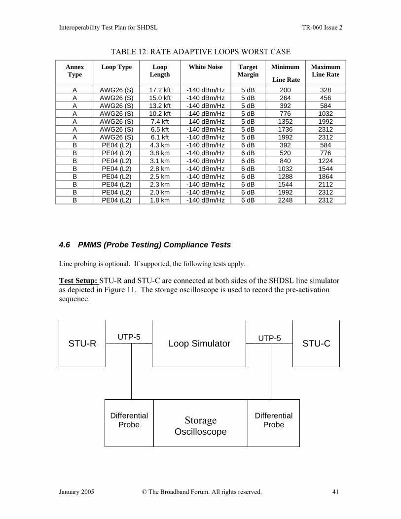
TABLE 12: RATE ADAPTIVE LOOPS WORST CASE
Annex Type
Loop Type Loop Length
White Noise Target Margin
Minimum
Line Rate
Maximum Line Rate
A AWG26 (S) 17.2 kft -140 dBm/Hz 5 dB 200 328 A AWG26 (S) 15.0 kft -140 dBm/Hz 5 dB 264 456 A AWG26 (S) 13.2 kft -140 dBm/Hz 5 dB 392 584 A AWG26 (S) 10.2 kft -140 dBm/Hz 5 dB 776 1032 A AWG26 (S) 7.4 kft -140 dBm/Hz 5 dB 1352 1992 A AWG26 (S) 6.5 kft -140 dBm/Hz 5 dB 1736 2312 A AWG26 (S) 6.1 kft -140 dBm/Hz 5 dB 1992 2312 B PE04 (L2) 4.3 km -140 dBm/Hz 6 dB 392 584 B PE04 (L2) 3.8 km -140 dBm/Hz 6 dB 520 776 B PE04 (L2) 3.1 km -140 dBm/Hz 6 dB 840 1224 B PE04 (L2) 2.8 km -140 dBm/Hz 6 dB 1032 1544 B PE04 (L2) 2.5 km -140 dBm/Hz 6 dB 1288 1864 B PE04 (L2) 2.3 km -140 dBm/Hz 6 dB 1544 2112 B PE04 (L2) 2.0 km -140 dBm/Hz 6 dB 1992 2312 B PE04 (L2) 1.8 km -140 dBm/Hz 6 dB 2248 2312
4.6 PMMS (Probe Testing) Compliance Tests Line probing is optional. If supported, the following tests apply. Test Setup: STU-R and STU-C are connected at both sides of the SHDSL line simulator as depicted in Figure 11. The storage oscilloscope is used to record the pre-activation sequence.
STU-R STU-C Loop Simulator UTP-5 UTP-5
Storage
Oscilloscope
Differential
Probe
Differential
Probe
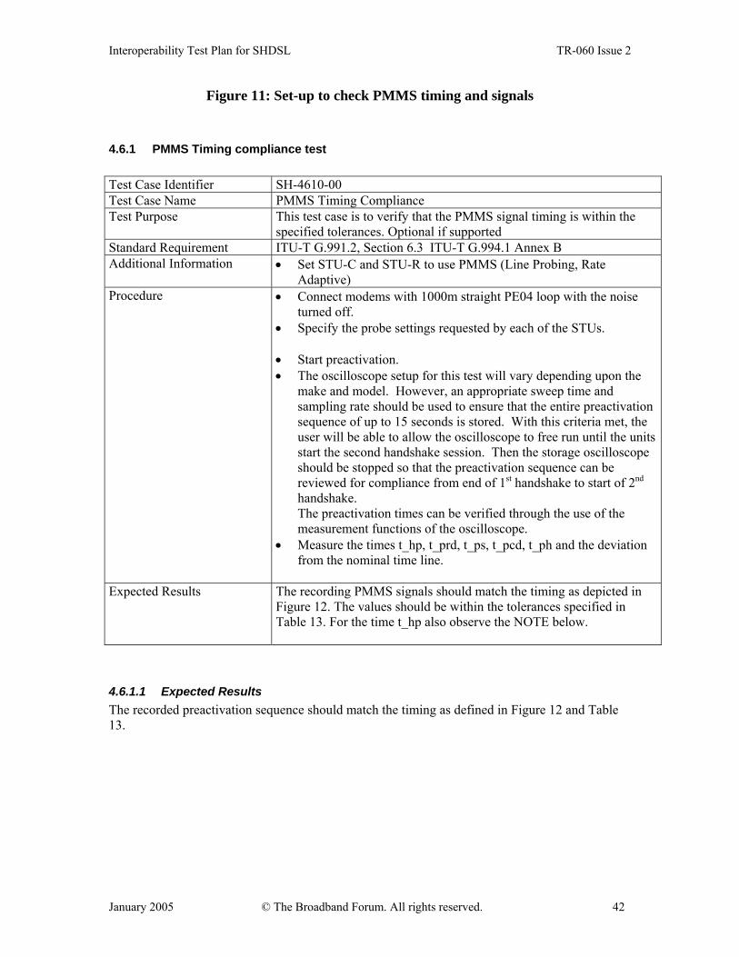
Interoperability Test Plan for SHDSL TR-060 Issue 2
January 2005 © The Broadband Forum. All rights reserved. 42
Figure 11: Set-up to check PMMS timing and signals
4.6.1 PMMS Timing compliance test Test Case Identifier SH-4610-00 Test Case Name PMMS Timing Compliance Test Purpose This test case is to verify that the PMMS signal timing is within the
specified tolerances. Optional if supported Standard Requirement ITU-T G.991.2, Section 6.3 ITU-T G.994.1 Annex B Additional Information • Set STU-C and STU-R to use PMMS (Line Probing, Rate
Adaptive) Procedure
• Connect modems with 1000m straight PE04 loop with the noise turned off.
• Specify the probe settings requested by each of the STUs.
• Start preactivation. • The oscilloscope setup for this test will vary depending upon the
make and model. However, an appropriate sweep time and sampling rate should be used to ensure that the entire preactivation sequence of up to 15 seconds is stored. With this criteria met, the user will be able to allow the oscilloscope to free run until the units start the second handshake session. Then the storage oscilloscope should be stopped so that the preactivation sequence can be reviewed for compliance from end of 1st handshake to start of 2nd handshake. The preactivation times can be verified through the use of the measurement functions of the oscilloscope.
• Measure the times t_hp, t_prd, t_ps, t_pcd, t_ph and the deviation from the nominal time line.
Expected Results The recording PMMS signals should match the timing as depicted in
Figure 12. The values should be within the tolerances specified in Table 13. For the time t_hp also observe the NOTE below.
4.6.1.1 Expected Results The recorded preactivation sequence should match the timing as defined in Figure 12 and Table 13.

Interoperability Test Plan for SHDSL TR-060 Issue 2
January 2005 © The Broadband Forum. All rights reserved. 43
T1541240-00
G.994.1 G.994.1
Pr1 Pr2 Pr3
tprd tprd tprdthp tps tps tprc
tpcd tps tpcd tph
Pc1 Pc2
STU-C
STU-R
Figure 12: Typical timing diagram for pre-activation sequence
TABLE 13: TIMING FOR PRE-ACTIVATION SIGNALS
Time Parameter Nominal value Tolerance
thp Time from end of handshake to start of remote probe 0.2 s ±10 ms
tprd Duration of remote probe Selectable from 50 ms to 3.1 s
±10 ms
tps Time separating two probe sequences 0.2 s ±10 ms
tprc Time separating last remote and first central probe sequences 0.2 s ±10 ms
tpcd Duration of central probe Selectable from 50 ms to 3.1 s
±10 ms
tph Time from end of central probe to start of handshake 0.2 s ±10 ms
tp-total Total probe duration, from end of the first G.994.1 session to the start of the second G.994.1 session
10 s maximum
NOTE − Tolerances are relative to the nominal or ideal value. They are not cumulative across the pre-activation sequence.
IMPORTANT NOTE: Concerning the time t_hp the following points are to consider:
• According to G.994.1 the end of G.handshake can differ on COT and CPE side by up to 500ms. Therefore it would be possible that the COT is still in its handshake procedure while the CPE is already sending its remote probes. Thus the end of handshake should be defined more accurate when starting a PMMS session afterwards.
• For purposes of this test, it is proposed that the end of the handshake session is the point of time when the closing GALF signal ends, for both the COT and the CPE, with a

Interoperability Test Plan for SHDSL TR-060 Issue 2
January 2005 © The Broadband Forum. All rights reserved. 44
tolerance of +/- 10ms.The CPE shall send its remote probes t_hp after this point in time and the COT shall be ready to receive the remote probes t_hp after this point in time.
4.6.2 PMMS Signal Compliance Test
Test setup STU-R and STU-C are connected at both sides of the SHDSL line simulator as depicted in Figure 11. The loop length should be 1000m. The storage oscilloscope is used to record the preactivation sequence, from which the signals can be taken. The test shall be performed with the noise generator removed or turned off. The devices shall be in normal operational mode using PMMS (rate adaptive). Test Case Identifier SH-4640-00 Test Case Name PMMS Signal Compliance Test Purpose This test case is to verify that the PMMS probe signals and silence
signals are within certain tolerances to ensure PMMS interoperability between different devices.
Standard Requirement ITU-T G.991.2, Section 6.3, ITU-T G.994.1 Annex B Additional Information • Set STU-C and STU-R to use PMMS (Line Probing, Rate
Adaptive). Optional if supported Procedure
• Connect modems with 0m loop with the noise turned off. • Specify the probe settings requested by each of the STUs. • Start preactivation. • The oscilloscope setup for this test will vary depending upon the
make and model. However, an appropriate sweep time, sampling rate and amplitude resolution should be used to ensure that silence and probe signals are stored properly. With this criteria met, the user will be able to allow the oscilloscope to free run until the preactivation signals of interest are transmitted. Then the storage oscilloscope should be stopped so that the preactivation signals can be reviewed for compliance. The preactivation signals can be verified through the use of the measurement functions of the oscilloscope.
• Check the quality of all probe signals and of the silence signals from handshake to first remote probe and between subsequent probes.
Expected Results The transmit power of the recorded probe signals should be within the
requirements specified in G.991.2. The recorded silence signal between handshake and the first remote probe and between all other probes shall fulfill the requirements specified below.

Interoperability Test Plan for SHDSL TR-060 Issue 2
January 2005 © The Broadband Forum. All rights reserved. 45
4.6.2.1 Expected results As specified in G.991.2 the probe signals Pci and Pri should be sent with the same signal power level as during activation, i.e. nominally 13.5dBm for annex A or 14.5dBm for annex B, rates >= 2048kbps. For the purpose of this test, it is proposed that the silence signal between handshake and the first remote probe and between all other probes shall fulfill following restrictions: • The average silence power transmitted should be at any time at least 40dB lower than the
transmitted probe signal power. • The amplitude of the transmitted signal from the transceiver at silence condition should at no
time exceed a level of 30dB lower than the maximum probe signal amplitude.
4.7 4-Wire Mode
4.7.1 4-Wire Mode start-up description
• R-Tones-Req (for STU-R initiated start-up) and C-Tones shall be transmitted simultaneously on all available wire pairs.
• The STU-R shall then select an active wire pair from the set of pairs on which it receives C-Tones.
• R-Tone1, R-Flag1, and all succeeding signals transmitted by the HSTU-R shall only be transmitted on the selected active wire pair. Silence shall be sent on the other pairs.
• The STU-C shall designate the pair on which R-Tone1 and/or R-Flag1 is received as its active pair.
• All succeeding signals transmitted by the STU-C shall only be transmitted on the designated active wire pair. Silence shall be sent on the other pairs.
• The active pair is referred to as Pair1 (“Master”) while the second, not active, pair is named Pair2 (“Slave”).

Interoperability Test Plan for SHDSL TR-060 Issue 2
January 2005 © The Broadband Forum. All rights reserved. 46
Figure 13: 4-Wire Mode Start-up STU-C:
Time Parameter Nominal Value TG2A Time from end of handshake to start of
activation, i.e. the remote signal Cr (Cr is variable, see Note below.)
Pair 1: 0.34 < TG2A ≤ 1.3 sec Pair 2: 0.34 < TG2A ≤ 1.3 sec
STU-R: TG2A Time from end of handshake to start of
activation, i.e. the remote signal Cr Pair 1: 0.34 < TG2A < 1.3 sec Pair 2: 0.34 < TG2A < 1. 3 sec
NOTE: According to Amendment 1 of Recommendation G.991.2, “The end of preactivation can be defined in two ways according to the G.994.1 document. For the purpose of this Recommendation, the end of preactivation will be from the end of the ACK (1) message transmission plus the required timers. The minimum and maximum values of those timers are 0.04 and 1.0 second. Therefore, the total time between the end of ACK(1) message and the beginning of Cr should be between 0.34 and 1.3 s.”
4.7.2 4-Wire Mode start-up description with Lineprobing The first G.994.1 exchange shall follow the defined procedures for multi-pair operation ( ITU-T G.994.1 Annex B), as described in the previous chapter. The Lineprobing Signals (ITU-T G.991.2 clause 6.3.2), shall be sent in parallel on both wire pairs. Pair 1 and Pair 2 shall be determined during the first preactivation sequence. The second G.994.1 exchange shall only be performed on Pair 1, i.e. on Pair 2 no signal is transmitted after Lineprobing.
G.hs G.994.1
Activation
Activation
Pair1:
Pair2: R-Tones-Req
TG2A
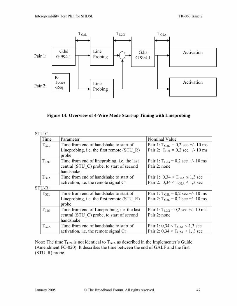
Interoperability Test Plan for SHDSL TR-060 Issue 2
January 2005 © The Broadband Forum. All rights reserved. 47
Figure 14: Overview of 4-Wire Mode Start-up Timing with Lineprobing STU-C:
Time Parameter Nominal Value TG2L Time from end of handshake to start of
Lineprobing, i.e. the first remote (STU_R) probe
Pair 1: TG2L = 0,2 sec +/- 10 ms Pair 2: TG2L = 0,2 sec +/- 10 ms
TL2G Time from end of lineprobing, i.e. the last central (STU_C) probe, to start of second handshake
Pair 1: TL2G = 0,2 sec +/- 10 ms Pair 2: none
TG2A Time from end of handshake to start of activation, i.e. the remote signal Cr
Pair 1: 0,34 < TG2A ≤ 1,3 sec Pair 2: 0,34 < TG2A ≤ 1,3 sec
STU-R: TG2L Time from end of handshake to start of
Lineprobing, i.e. the first remote (STU_R) probe
Pair 1: TG2L = 0,2 sec +/- 10 ms Pair 2: TG2L = 0,2 sec +/- 10 ms
TL2G Time from end of Lineprobing, i.e. the last central (STU_C) probe, to start of second handshake
Pair 1: TL2G = 0,2 sec +/- 10 ms Pair 2: none
TG2A Time from end of handshake to start of activation, i.e. the remote signal Cr
Pair 1: 0,34 < TG2A < 1,3 sec Pair 2: 0,34 < TG2A < 1, 3 sec
Note: The time TG2L is not identical to TG2A as described in the Implementer’s Guide (Amendment FC-020). It describes the time between the end of GALF and the first (STU_R) probe.
G.hs G.994.1
G.hs G.994.1
Line Probing
Activation
TG2L TL2G TG2A
Line Probing
Activation
Pair 1:
Pair 2:
R-Tones-Req

Interoperability Test Plan for SHDSL TR-060 Issue 2
January 2005 © The Broadband Forum. All rights reserved. 48
4.7.3 Test Setup STU-R and STU-C are connected together as depicted in Figure 15. The storage oscilloscope is used to record the pre-activation sequence, Test Case Identifier SH-4730-00 Test Case Name 4-Wire Mode startup test Test Purpose To verify the correct start-up of the DTUs in 4-wire mode with
and without lineprobing. These modes are optional and may not be supported by all devices.
Standard Requirement ITU-T G.994.1 Annex B ITU-T G.991.2 clause 6.3
Additional Information • during time TG2A both STU’s shall transmit silence • See 4.7.1 4-Wire Mode Description and 4.7.2 4-Wire Mode Description with Lineprobing • both pairs shall the core activation at the same time.
Therefore they should reach data mode nearly simultaneously.
• The core activation is identical to the 2-wire mode and can be tested according to appropriate procedures as described in the previous chapters.
Procedure • Connect modems according to test setup • The oscilloscope setup for the 4-wire sequence timing test
will vary depending upon the make and model. However, an appropriate sweep time and sampling rate should be used to ensure that the entire 4-wire sequence of up to 25 seconds is stored. With this criteria met, the user will be able to allow the oscilloscope to free run until the units achieve data mode. Then the storage oscilloscope should be stopped so that the 4-wire sequence can be reviewed for compliance. The 4-wire timing can be verified through the use of the measurement functions of the oscilloscope.
• Measure TG2L, TL2G, TG2A. • Check if during time TG2A both STU’s are transmitting
silence • Check if both pairs are starting their Cr Signal
simultaneously • Repeat the above procedure with crossed wire pairs.
Expected Results The recorded 4-Wire Mode sequence should be as shown in Figure 13 and Figure 14. The recorded timing values should be within the tolerances specified in the Tables above. In all cases, also with switched pairs, data shall be transmitted correctly.

Interoperability Test Plan for SHDSL TR-060 Issue 2
January 2005 © The Broadband Forum. All rights reserved. 49
Loop Simulator
Loop Simulator UTP-5
STU-R STU-C
UTP-5
Storage
Oscilloscope
2x
Differential Probe
2x
Differential Probe
Figure 15: Test Setup to Check 4-Wire Mode Start-up with Lineprobing
5 System Interoperability The Embedded Operations Channel (EOC) allows terminal units to maintain information about the connection or span, and commands requesting certain actions to be taken by a STU-x unit. There are two basic categories of flows, differentiated by which unit initiates the data flow (and subsequently stores the information for external access). The data flow origination form the STU-C is mandatory. The data flow initiating from the STU-R is optional, but all units (repeaters/regenerators) must respond to requests in either direction of data flow. In all cases, the “master database” shall be stored at the STU-C and all conflicts shall be resolved in favor of the STU-C. When the optional 4-wire mode is supported, the same EOC message is required to be passed by both loops. To verify, apply the following test cases either using one in Data mode and the other disconnected or both in data mode. EOC messages are a key part of the start-up procedures and includes Discovery, Inventory, and Configuration Responses from remote units during startup before going in service. Incorrect implementation of the EOC has been a common cause of interoperability problems. Correct responses enable the network to "see" what types of units are connected (CPE and/or repeaters), identify the vendor, what software is running, etc. Other messages are sent during startup but they should not affect going into service. Some hints where problems frequently occur include: • All EOC messages should have correct message length • Discovery Response (#129) must have a valid hop count (incremented +1). See
Recommendation G.991.2 Section 9.5.5.7.2.

Interoperability Test Plan for SHDSL TR-060 Issue 2
January 2005 © The Broadband Forum. All rights reserved. 50
• Configuration Request threshold settings default to 0, which means they are turned off. If an STU-R does not support threshold configuration, it should first check if the request is to turn off the thresholds. If so, send a Configuration Response that acknowledges that the thresholds have been turned off.
• The STU-R must implement the power status bit (ps bit) in the overhead of the SHDSL frame. Otherwise, a Loss of Power (LPR) alarm will be generated and prevent the line from achieving or maintaining sync. (See G.991.2 Frame Structure Table 7-1 in Section 7.1.2.5.3).
The EOC Maintenance Requests provide another category of important messages to enable performance status, ATM cell status, loopback, loopback timeout, and soft restart messages to be communicated, and are important to operators. The EOC critical messaging capabilities are verified in the test cases contained in the following sections.
5.1 Loop back Control Structure Tests The Loop back Control Structure tests will apply to STU devices depending on function. The two types of operation are CO Control Mode and Remote Control Mode.
5.1.1 CO Control Mode The following tests are applicable when the user is controlling all loop backs at the STU-C. If 4-wire mode is supported, the same test should be applied to each pair. 5.1.1.1 CO Control Mode: System Loop back Message (9) Broadcast This set of tests is applicable for any STU-R when the STU-C controls loop back with a system loop back message broadcast to the other units in this system. 5.1.1.1.1 Network Loop back at Remote A) Activate Network Loop back at Remote Test Case Identifier SH-5111-10 Test Case Name Loop Back at Remote Test Purpose Test loop back activation from remote equipment Standard Requirement Procedure Activate network loop back at remote from CO unit Expected Results • Verify control for initiate loop back toward the
network in command for STU-R (octet 3 bit 3) set in system loop back message
• Verify error free payload data looped back towards network
• Verify maintenance status message from remote in response to status request message (msg id 11)

Interoperability Test Plan for SHDSL TR-060 Issue 2
January 2005 © The Broadband Forum. All rights reserved. 51
indicates a network loop back is active at remote (octet 2 bit 3)
B) Deactivate Network Loop back at Remote Test both methods of deactivation Test Case Identifier SH-5111-11 Test Case Name Deactivate Network Loop back at Remote Test Purpose Test correct deactivation Standard Requirement Procedure Deactivate loop back at remote to network from CO unit
using terminate loop back toward network in system loop back message.
Expected Results • Verify control for terminate loop back toward the network in command for STU-R (octet 3 bit 1) set in system loop back message.
• Verify loop back dropped and data path restored. • Verify maintenance status message from remote in
response to status request message (Msg id 11) immediately after looping down indicates a network loop back is no longer active at remote (octet 2, bit3).
Test Case Identifier SH-5111-12 Test Case Name Deactivate Network Loop back at Remote Test Purpose Test correct deactivation Standard Requirement Procedure Deactivate loop back at remote to network from CO unit
using clear all maintenance states in system loop back message.
Expected Results • Verify control for clear all maintenance states in command for STU-R (octet 3, bit 6) in system loop back message
• Verify loop back dropped and data path restored. • Verify maintenance status message from remote in
response to status request message (Msg id 11) immediately after looping down indicates a network loop back is no longer active at remote (octet 2, bit 3).
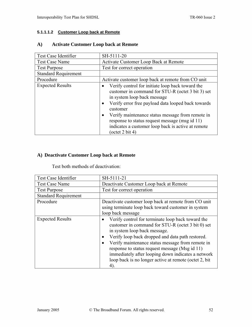
Interoperability Test Plan for SHDSL TR-060 Issue 2
January 2005 © The Broadband Forum. All rights reserved. 52
5.1.1.1.2 Customer Loop back at Remote A) Activate Customer Loop back at Remote Test Case Identifier SH-5111-20 Test Case Name Activate Customer Loop Back at Remote Test Purpose Test for correct operation Standard Requirement Procedure Activate customer loop back at remote from CO unit Expected Results • Verify control for initiate loop back toward the
customer in command for STU-R (octet 3 bit 3) set in system loop back message
• Verify error free payload data looped back towards customer
• Verify maintenance status message from remote in response to status request message (msg id 11) indicates a customer loop back is active at remote (octet 2 bit 4)
A) Deactivate Customer Loop back at Remote
Test both methods of deactivation:
Test Case Identifier SH-5111-21 Test Case Name Deactivate Customer Loop back at Remote Test Purpose Test for correct operation Standard Requirement Procedure Deactivate customer loop back at remote from CO unit
using terminate loop back toward customer in system loop back message
Expected Results • Verify control for terminate loop back toward the customer in command for STU-R (octet 3 bit 0) set in system loop back message.
• Verify loop back dropped and data path restored. • Verify maintenance status message from remote in
response to status request message (Msg id 11) immediately after looping down indicates a network loop back is no longer active at remote (octet 2, bit 4).

Interoperability Test Plan for SHDSL TR-060 Issue 2
January 2005 © The Broadband Forum. All rights reserved. 53
Test Case Identifier SH-5111-22 Test Case Name Deactivate Customer Loop back at Remote Test Purpose Test for correct operation Standard Requirement Procedure Deactivate loop back at remote to customer from CO
unit using clear all maintenance states in system loop back message.
Expected Results • Verify only control for clear all maintenance states in command for STU-R (octet 3, bit 6) in system loop back message
• Verify back dropped and data path restores. • Verify maintenance status message from remote in
response to status request message (Msg id 11) immediately after looping down indicates a network loop back is no longer active at remote (octet 2, bit 4).
5.1.1.1.3 Bi-directional Loop back at Remote (If supported by both ends)
A) Activate Bi-directional Loop back at Remote Test Case Identifier SH-5111-30 Test Case Name Activate Bi-directional Loop back at Remote Test Purpose Test for correct operation Standard Requirement Additional Information (Note may have to activate one direction at a time) Procedure Activate bi-directional loop back at remote from CO
unit. Expected Results • Verify control for initiate loop back toward the
network and customer in command for STU-R (octet 3, bit 2 and 3) are set in system loop back message.
• Verify error free payload data looped back towards both network and customer
• Verify maintenance status message from remote to CO in response to status request message (msg id 11) indicates network and customer Loop backs are active at remote (octet 2, bit 3 and 4)
• If the remote cannot support multiple loop back requests, it shall respond with a maintenance status message that indicates its current active loop back.
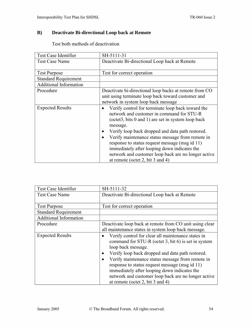
Interoperability Test Plan for SHDSL TR-060 Issue 2
January 2005 © The Broadband Forum. All rights reserved. 54
B) Deactivate Bi-directional Loop back at Remote
Test both methods of deactivation
Test Case Identifier SH-5111-31 Test Case Name Deactivate Bi-directional Loop back at Remote
Test Purpose Test for correct operation Standard Requirement Additional Information Procedure Deactivate bi-directional loop backs at remote from CO
unit using terminate loop back toward customer and network in system loop back message
Expected Results • Verify control for terminate loop back toward the network and customer in command for STU-R (octet3, bits 0 and 1) are set in system loop back message.
• Verify loop back dropped and data path restored. • Verify maintenance status message from remote in
response to status request message (msg id 11) immediately after looping down indicates the network and customer loop back are no longer active at remote (octet 2, bit 3 and 4)
Test Case Identifier SH-5111-32 Test Case Name Deactivate Bi-directional Loop back at Remote
Test Purpose Test for correct operation Standard Requirement Additional Information Procedure Deactivate loop back at remote from CO unit using clear
all maintenance states in system loop back message. Expected Results • Verify control for clear all maintenance states in
command for STU-R (octet 3, bit 6) is set in system loop back message.
• Verify loop back dropped and data path restored. • Verify maintenance status message from remote in
response to status request message (msg id 11) immediately after looping down indicates the network and customer loop back are no longer active at remote (octet 2, bit 3 and 4)

Interoperability Test Plan for SHDSL TR-060 Issue 2
January 2005 © The Broadband Forum. All rights reserved. 55
5.1.1.1.4 Special Loop back at Remote (if supported)
A) Activate Special Loop back at Remote to Network Test Case Identifier SH-5111-40 Test Case Name Activate Special Loop back at Remote to Network
Test Purpose Test for correct operation if supported Standard Requirement Additional Information Procedure Activate special loop back to network from CO unit.
Expected Results • Verify control for special remote loop back (Octet 3,
bit 5) is set in system loop back message. • Verify error free payload data is looped back towards
network • Verify maintenance status message from remote in
response to status request message (msg id 11) indicates a special loop back is active at remote (octet 2, bit 5)
B) Deactivate Network Loop back Remote to Network Test Case Identifier SH-5111-41 Test Case Name Deactivate Network Loop back Remote to Network
Test Purpose Test for correct operation if supported Standard Requirement Additional Information Procedure Deactivate loop back at remote to network from CO unit
using terminate special loop back (octet 3 bit4) in system loop back message
Expected Results • Verify control for clear all maintenance states in command for STU-R (octet 3, bit 6) is set in system loop back message.
• Verify loop back dropped and data path restored. • Verify maintenance status message from remote in
response to status request message (msg id 11) immediately after looping down indicates a network loop back is no longer active at remote (octet 2, bit 4)
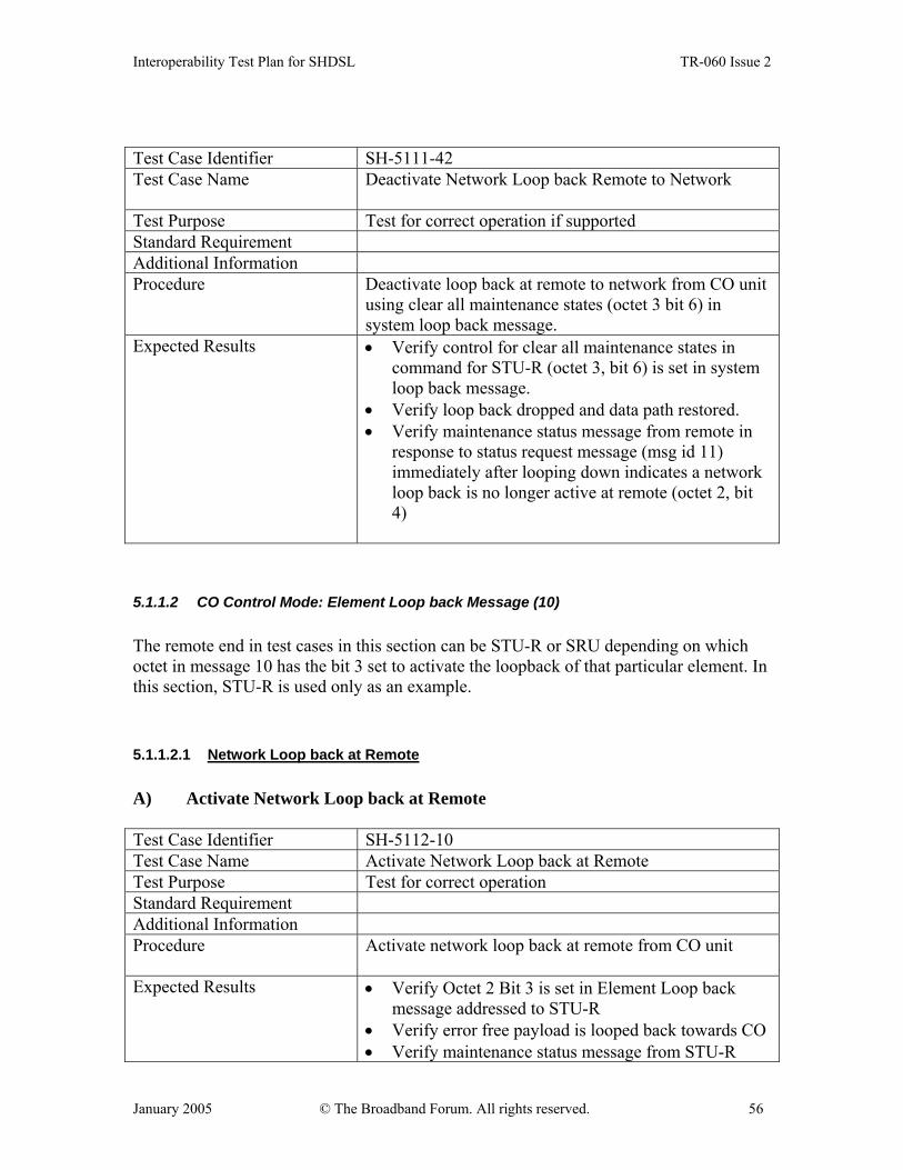
Interoperability Test Plan for SHDSL TR-060 Issue 2
January 2005 © The Broadband Forum. All rights reserved. 56
Test Case Identifier SH-5111-42 Test Case Name Deactivate Network Loop back Remote to Network
Test Purpose Test for correct operation if supported Standard Requirement Additional Information Procedure Deactivate loop back at remote to network from CO unit
using clear all maintenance states (octet 3 bit 6) in system loop back message.
Expected Results • Verify control for clear all maintenance states in command for STU-R (octet 3, bit 6) is set in system loop back message.
• Verify loop back dropped and data path restored. • Verify maintenance status message from remote in
response to status request message (msg id 11) immediately after looping down indicates a network loop back is no longer active at remote (octet 2, bit 4)
5.1.1.2 CO Control Mode: Element Loop back Message (10) The remote end in test cases in this section can be STU-R or SRU depending on which octet in message 10 has the bit 3 set to activate the loopback of that particular element. In this section, STU-R is used only as an example. 5.1.1.2.1 Network Loop back at Remote A) Activate Network Loop back at Remote Test Case Identifier SH-5112-10 Test Case Name Activate Network Loop back at Remote Test Purpose Test for correct operation Standard Requirement Additional Information Procedure Activate network loop back at remote from CO unit
Expected Results • Verify Octet 2 Bit 3 is set in Element Loop back
message addressed to STU-R • Verify error free payload is looped back towards CO • Verify maintenance status message from STU-R

Interoperability Test Plan for SHDSL TR-060 Issue 2
January 2005 © The Broadband Forum. All rights reserved. 57
indicates a loop back is active towards STU-C (Octet 2, Bit 3)
B) Deactivate Network Loop back at Remote
Test both methods of deactivation
Test Case Identifier SH-5112-11 Test Case Name Deactivate Network Loop back at Remote Test Purpose Test for correct operation Standard Requirement Additional Information Procedure Deactivate loop back at remote to network from CO unit
using terminate loop back toward network in element loop back message.
Expected Results • Verify control for terminate loop back toward the network (octet 2, bit 1) is set in element loop back message.
• Verify loop back dropped and data path restored. • Verify maintenance status message from remote
indicates a network loop back is no longer active at remote (octet 2, bit3).
Test Case Identifier SH-5112-12 Test Case Name Deactivate Network Loop back at Remote Test Purpose Test for correct operation Standard Requirement Additional Information Procedure Deactivate loop back at remote to network from CO
unit. Using clear all maintenance states in element loop back message.
Expected Results • Verify control for clear all maintenance states (octet 2, bit 6) is set in element loop back message
• Verify loop back dropped and data path restored. • Verify maintenance status message from remote
indicates a network loop back is no longer active at remote (octet 2, bit3).
5.1.1.2.2 Customer Loopback at Remote
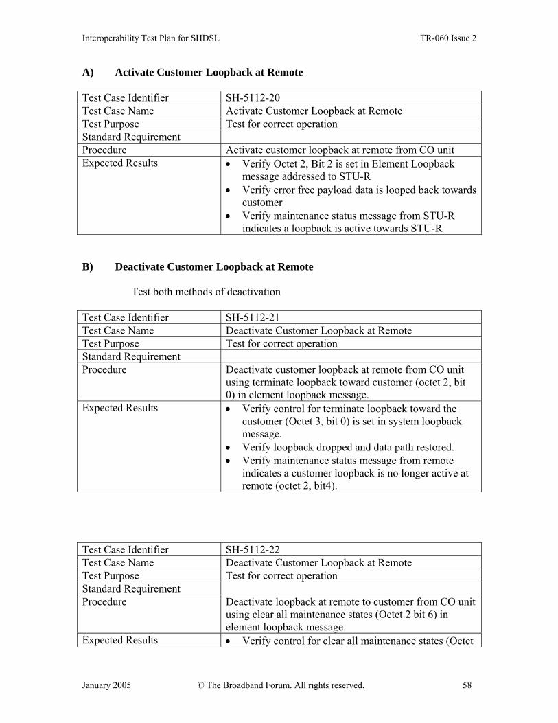
Interoperability Test Plan for SHDSL TR-060 Issue 2
January 2005 © The Broadband Forum. All rights reserved. 58
A) Activate Customer Loopback at Remote Test Case Identifier SH-5112-20 Test Case Name Activate Customer Loopback at Remote Test Purpose Test for correct operation Standard Requirement Procedure Activate customer loopback at remote from CO unit Expected Results • Verify Octet 2, Bit 2 is set in Element Loopback
message addressed to STU-R • Verify error free payload data is looped back towards
customer • Verify maintenance status message from STU-R
indicates a loopback is active towards STU-R B) Deactivate Customer Loopback at Remote
Test both methods of deactivation
Test Case Identifier SH-5112-21 Test Case Name Deactivate Customer Loopback at Remote Test Purpose Test for correct operation Standard Requirement Procedure Deactivate customer loopback at remote from CO unit
using terminate loopback toward customer (octet 2, bit 0) in element loopback message.
Expected Results • Verify control for terminate loopback toward the customer (Octet 3, bit 0) is set in system loopback message.
• Verify loopback dropped and data path restored. • Verify maintenance status message from remote
indicates a customer loopback is no longer active at remote (octet 2, bit4).
Test Case Identifier SH-5112-22 Test Case Name Deactivate Customer Loopback at Remote Test Purpose Test for correct operation Standard Requirement Procedure Deactivate loopback at remote to customer from CO unit
using clear all maintenance states (Octet 2 bit 6) in element loopback message.
Expected Results • Verify control for clear all maintenance states (Octet
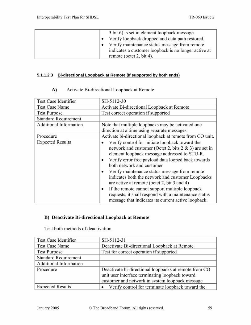
Interoperability Test Plan for SHDSL TR-060 Issue 2
January 2005 © The Broadband Forum. All rights reserved. 59
3 bit 6) is set in element loopback message • Verify loopback dropped and data path restored. • Verify maintenance status message from remote
indicates a customer loopback is no longer active at remote (octet 2, bit 4).
5.1.1.2.3 Bi-directional Loopback at Remote (If supported by both ends)
A) Activate Bi-directional Loopback at Remote Test Case Identifier SH-5112-30 Test Case Name Activate Bi-directional Loopback at Remote Test Purpose Test correct operation if supported Standard Requirement Additional Information Note that multiple loopbacks may be activated one
direction at a time using separate messages Procedure Activate bi-directional loopback at remote from CO unit.Expected Results • Verify control for initiate loopback toward the
network and customer (Octet 2, bits 2 & 3) are set in element loopback message addressed to STU-R.
• Verify error free payload data looped back towards both network and customer
• Verify maintenance status message from remote indicates both the network and customer Loopbacks are active at remote (octet 2, bit 3 and 4)
• If the remote cannot support multiple loopback requests, it shall respond with a maintenance status message that indicates its current active loopback.
B) Deactivate Bi-directional Loopback at Remote
Test both methods of deactivation
Test Case Identifier SH-5112-31 Test Case Name Deactivate Bi-directional Loopback at Remote Test Purpose Test for correct operation if supported Standard Requirement Additional Information Procedure Deactivate bi-directional loopbacks at remote from CO
unit user interface terminating loopback toward customer and network in system loopback message
Expected Results • Verify control for terminate loopback toward the
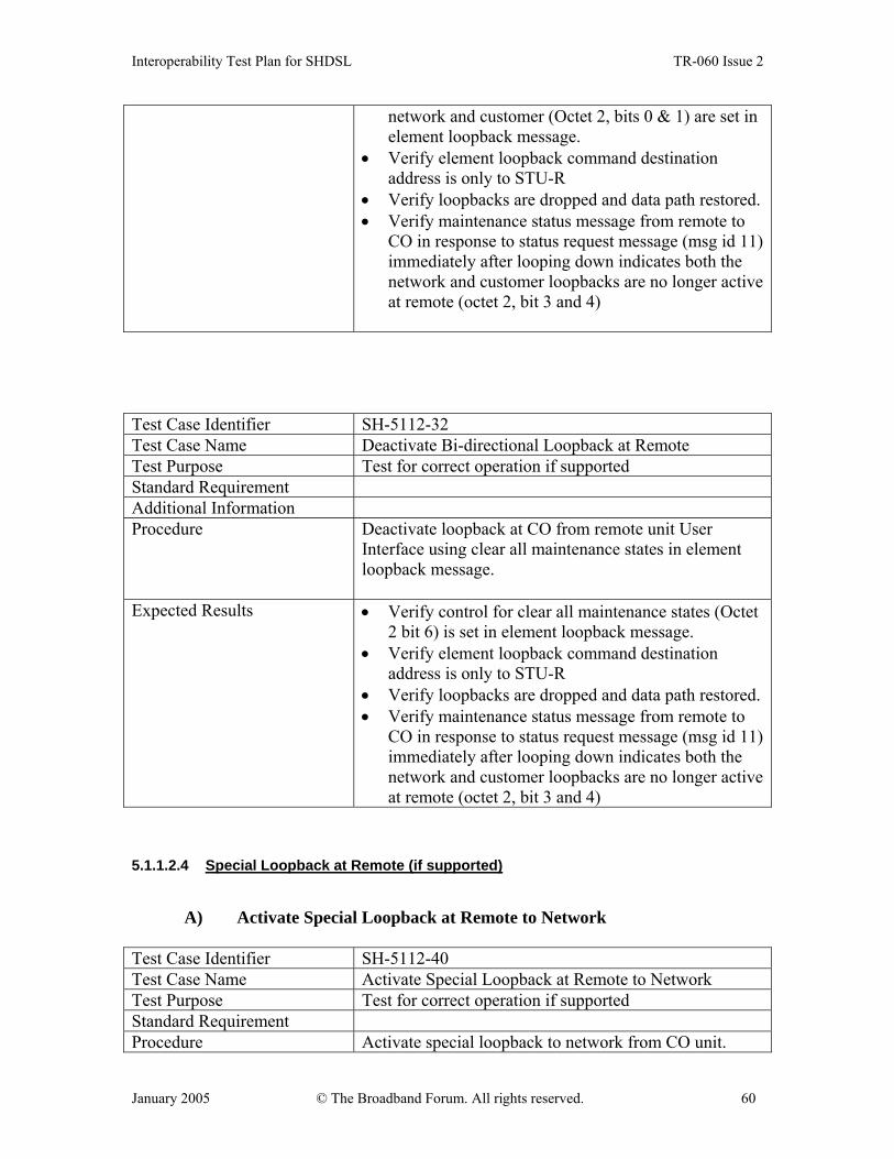
Interoperability Test Plan for SHDSL TR-060 Issue 2
January 2005 © The Broadband Forum. All rights reserved. 60
network and customer (Octet 2, bits 0 & 1) are set in element loopback message.
• Verify element loopback command destination address is only to STU-R
• Verify loopbacks are dropped and data path restored. • Verify maintenance status message from remote to
CO in response to status request message (msg id 11) immediately after looping down indicates both the network and customer loopbacks are no longer active at remote (octet 2, bit 3 and 4)
Test Case Identifier SH-5112-32 Test Case Name Deactivate Bi-directional Loopback at Remote Test Purpose Test for correct operation if supported Standard Requirement Additional Information Procedure Deactivate loopback at CO from remote unit User
Interface using clear all maintenance states in element loopback message.
Expected Results • Verify control for clear all maintenance states (Octet 2 bit 6) is set in element loopback message.
• Verify element loopback command destination address is only to STU-R
• Verify loopbacks are dropped and data path restored. • Verify maintenance status message from remote to
CO in response to status request message (msg id 11) immediately after looping down indicates both the network and customer loopbacks are no longer active at remote (octet 2, bit 3 and 4)
5.1.1.2.4 Special Loopback at Remote (if supported)
A) Activate Special Loopback at Remote to Network Test Case Identifier SH-5112-40 Test Case Name Activate Special Loopback at Remote to Network Test Purpose Test for correct operation if supported Standard Requirement Procedure Activate special loopback to network from CO unit.
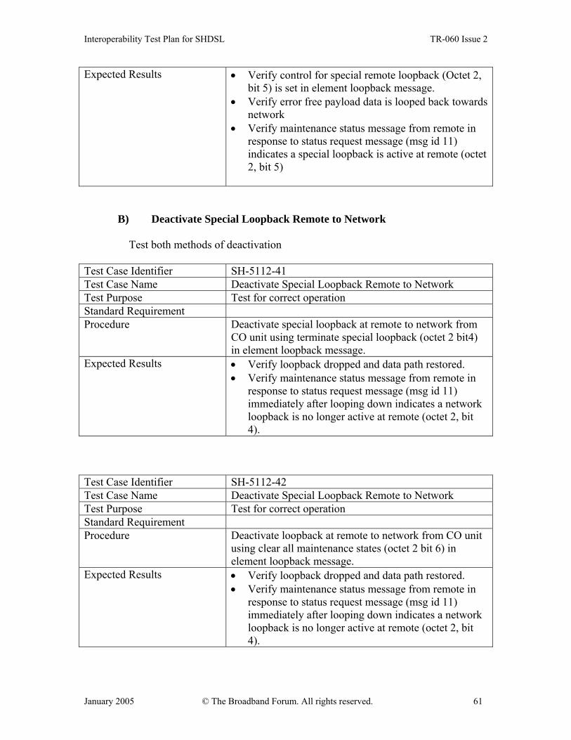
Interoperability Test Plan for SHDSL TR-060 Issue 2
January 2005 © The Broadband Forum. All rights reserved. 61
Expected Results • Verify control for special remote loopback (Octet 2, bit 5) is set in element loopback message.
• Verify error free payload data is looped back towards network
• Verify maintenance status message from remote in response to status request message (msg id 11) indicates a special loopback is active at remote (octet 2, bit 5)
B) Deactivate Special Loopback Remote to Network Test both methods of deactivation
Test Case Identifier SH-5112-41 Test Case Name Deactivate Special Loopback Remote to Network Test Purpose Test for correct operation Standard Requirement Procedure Deactivate special loopback at remote to network from
CO unit using terminate special loopback (octet 2 bit4) in element loopback message.
Expected Results • Verify loopback dropped and data path restored. • Verify maintenance status message from remote in
response to status request message (msg id 11) immediately after looping down indicates a network loopback is no longer active at remote (octet 2, bit 4).
Test Case Identifier SH-5112-42 Test Case Name Deactivate Special Loopback Remote to Network Test Purpose Test for correct operation Standard Requirement Procedure Deactivate loopback at remote to network from CO unit
using clear all maintenance states (octet 2 bit 6) in element loopback message.
Expected Results • Verify loopback dropped and data path restored. • Verify maintenance status message from remote in
response to status request message (msg id 11) immediately after looping down indicates a network loopback is no longer active at remote (octet 2, bit 4).

Interoperability Test Plan for SHDSL TR-060 Issue 2
January 2005 © The Broadband Forum. All rights reserved. 62
5.1.1.3 CO Control Mode: CO Loopback: Remote Display This test is for the STU-C that processes CO Loopbacks issued at the CO unit user interface locally with no remote unit involvement. 5.1.1.3.1 Network Loopback at CO A) Activate Network Loopback at CO Test Case Identifier SH-5113-10 Test Case Name Activate Network Loopback at CO Test Purpose Test for correct operation Standard Requirement Procedure Activate network loopback at CO from the CO unit user
interface. Expected Results • Verify error free payload is looped back towards
network • Verify maintenance status message from CO
indicates a network loopback is active at CO (Octet 2, Bit 3)
B) Deactivate Network Loopback at CO Test Case Identifier SH-5113-11 Test Case Name Deactivate Network Loopback at CO Test Purpose Verify correct operation Standard Requirement Procedure Deactivate network loopback at CO from CO unit user
interface. Expected Results • Verify loopback dropped and datapath restored
• Verify maintenance status message from CO to remote in response to status request message (Msg id 11) indicates the network loopback is no longer active at CO (octet2, bit 3).
5.1.1.3.2 Customer Loopback at CO A) Activate Customer Loopback at CO
Test Case Identifier SH-5113-20 Test Case Name Activate Customer Loopback at CO
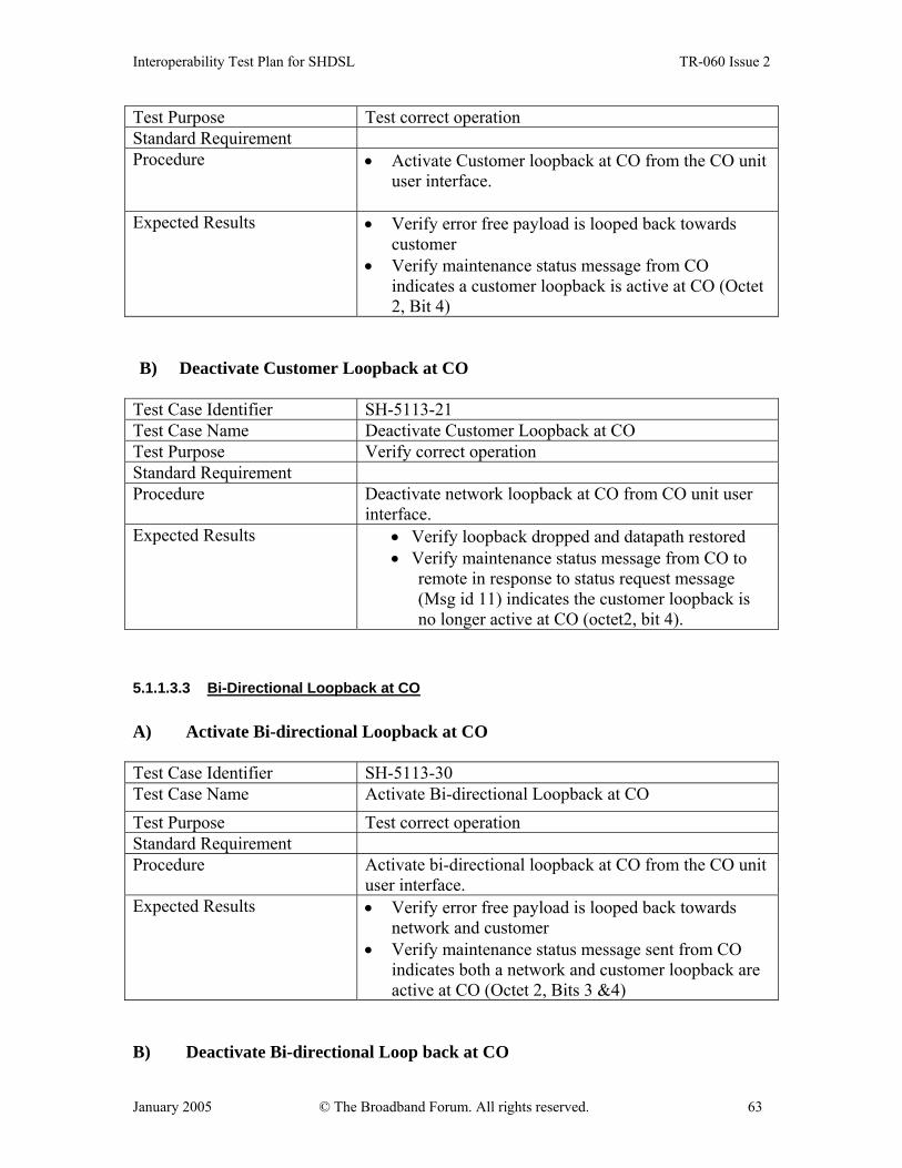
Interoperability Test Plan for SHDSL TR-060 Issue 2
January 2005 © The Broadband Forum. All rights reserved. 63
Test Purpose Test correct operation Standard Requirement Procedure • Activate Customer loopback at CO from the CO unit
user interface.
Expected Results • Verify error free payload is looped back towards customer
• Verify maintenance status message from CO indicates a customer loopback is active at CO (Octet 2, Bit 4)
B) Deactivate Customer Loopback at CO
Test Case Identifier SH-5113-21 Test Case Name Deactivate Customer Loopback at CO Test Purpose Verify correct operation Standard Requirement Procedure Deactivate network loopback at CO from CO unit user
interface. Expected Results • Verify loopback dropped and datapath restored
• Verify maintenance status message from CO to remote in response to status request message (Msg id 11) indicates the customer loopback is no longer active at CO (octet2, bit 4).
5.1.1.3.3 Bi-Directional Loopback at CO A) Activate Bi-directional Loopback at CO
Test Case Identifier SH-5113-30 Test Case Name Activate Bi-directional Loopback at CO Test Purpose Test correct operation Standard Requirement Procedure Activate bi-directional loopback at CO from the CO unit
user interface. Expected Results • Verify error free payload is looped back towards
network and customer • Verify maintenance status message sent from CO
indicates both a network and customer loopback are active at CO (Octet 2, Bits 3 &4)
B) Deactivate Bi-directional Loop back at CO

Interoperability Test Plan for SHDSL TR-060 Issue 2
January 2005 © The Broadband Forum. All rights reserved. 64
Test Case Identifier SH-5113-31 Test Case Name Deactivate Bi-directional Loop back at CO Test Purpose Test correct operation Standard Requirement Procedure Deactivate network loop back at CO from CO unit user
interface. Expected Results • Verify loop backs are dropped and data path
restored • Verify maintenance status message from CO to
remote in response to status request message (Msg id 11) indicates that both loop backs are no longer active at CO (octet2, bits 3 & 4)
5.1.2 Remote Control Mode The following tests are applicable when the user is controlling all loopbacks at the STU-R. Support of loopback initiated at the STU-R is optional. 5.1.2.1 Remote Control Mode: System Loop back Message (Msg id 9) This set of tests is applicable with any STU-C when the STU-R unit implements a System Loop back Message control to activate loop backs. 5.1.2.1.1 Network Loop back at CO Activate Network Loop back at Remote Test Case Identifier SH-5121-10 Test Case Name Activate Network Loop back at Remote Test Purpose Test correct operation Standard Requirement Procedure Activate network loop back at CO from Remote Unit
user interface Expected Results • Verify control for initiate loop back toward the
network in command for STU-C (octet 2 bit 3) set in system loopback message
• Verify error free payload data looped back towards network
• Verify System Loopback command destination address to only STU-C (Destination Address =1)
• Verify maintenance status message from CO to Remote in response to status request message (msg
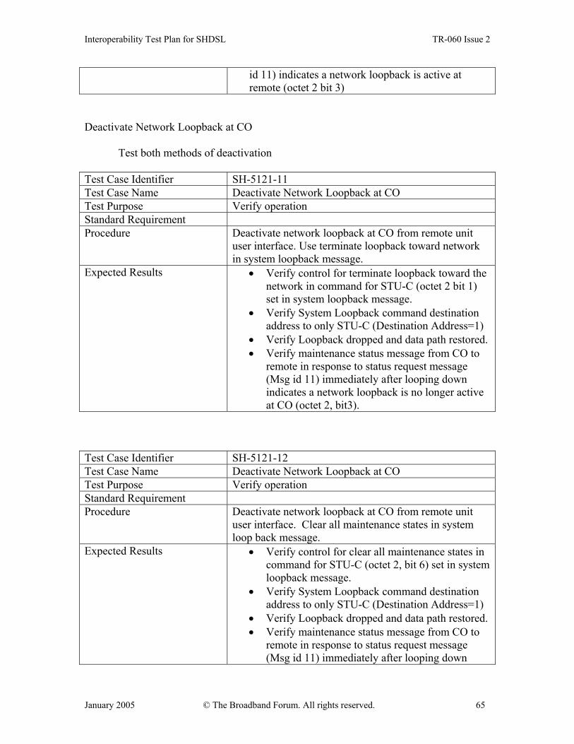
Interoperability Test Plan for SHDSL TR-060 Issue 2
January 2005 © The Broadband Forum. All rights reserved. 65
id 11) indicates a network loopback is active at remote (octet 2 bit 3)
Deactivate Network Loopback at CO
Test both methods of deactivation Test Case Identifier SH-5121-11 Test Case Name Deactivate Network Loopback at CO Test Purpose Verify operation Standard Requirement Procedure Deactivate network loopback at CO from remote unit
user interface. Use terminate loopback toward network in system loopback message.
Expected Results • Verify control for terminate loopback toward the network in command for STU-C (octet 2 bit 1) set in system loopback message.
• Verify System Loopback command destination address to only STU-C (Destination Address=1)
• Verify Loopback dropped and data path restored. • Verify maintenance status message from CO to
remote in response to status request message (Msg id 11) immediately after looping down indicates a network loopback is no longer active at CO (octet 2, bit3).
Test Case Identifier SH-5121-12 Test Case Name Deactivate Network Loopback at CO Test Purpose Verify operation Standard Requirement Procedure Deactivate network loopback at CO from remote unit
user interface. Clear all maintenance states in system loop back message.
Expected Results • Verify control for clear all maintenance states in command for STU-C (octet 2, bit 6) set in system loopback message.
• Verify System Loopback command destination address to only STU-C (Destination Address=1)
• Verify Loopback dropped and data path restored. • Verify maintenance status message from CO to
remote in response to status request message (Msg id 11) immediately after looping down

Interoperability Test Plan for SHDSL TR-060 Issue 2
January 2005 © The Broadband Forum. All rights reserved. 66
indicates a network loopback is no longer active at CO (octet 2, bit3).
5.1.2.1.2 Customer Loopback at CO Activate Customer Loopback at CO
Test Case Identifier SH-5121-20 Test Case Name Activate Customer Loopback at CO Test Purpose Test correct operation Standard Requirement Procedure Activate customer loopback at CO from remote unit user
interface Expected Results • Verify control for initiate loopback toward the
customer in command for STU-C (octet 2 bit 2) set in system loopback message
• Verify error free payload data looped back towards customer
• Verify System Loopback command destination address to only STU-C (Destination Address=1)
• Verify maintenance status message from CO to remote in response to status request message (msg id 11) indicates a customer loopback is active at CO (octet 2 bit 4)
Deactivate Customer Loopback at Remote Test both methods of deactivation Test Case Identifier SH-5121-21 Test Case Name Deactivate Customer Loopback at Remote Test Purpose Test operation Standard Requirement Procedure Deactivate customer loopback at CO from CO from
remote unit user interface using terminate loopback toward customer in system loopback message.
Expected Results • Verify control for terminate loopback toward the customer in command for STU-C (octet 2 bit 0) set in system loopback message.
• Verify loopback dropped and data path restores. • Verify System Loopback command destination
address to only STU-C (Destination Address=1) • Verify maintenance status message from CO to

Interoperability Test Plan for SHDSL TR-060 Issue 2
January 2005 © The Broadband Forum. All rights reserved. 67
remote in response to status request message (Msg id 11) immediately after looping down indicates a customer loopback is no longer active at remote (octet 2, bit4).
Test Case Identifier SH-5121-22 Test Case Name Deactivate Customer Loopback at Remote Test Purpose Test operation Standard Requirement Procedure Deactivate customer loopback at CO from remote unit
user interface using clear all maintenance states in system loop back message.
Expected Results • Verify control for clear all maintenance states in command for STU-C(octet 2, bit 6) set in system loopback message
• Verify loopback dropped and data path restores. • Verify System Loopback command destination
address to only STU-C (Destination Address=1) • Verify maintenance status message from CO to
remote in response to status request message (Msg id 11) immediately after looping down indicates a customer loopback is no longer active at remote (octet 2, bit4).
5.1.2.1.3 Bi-directional Loopback at CO (if supported by both ends) Activate Bi-directional Loopback at CO
Test Case Identifier SH-5121-30 Test Case Name Activate Bi-directional Loopback at CO Test Purpose Test correct operation if supported Standard Requirement Additional Information (Note: may have to activate one direction at a time) Procedure Activate bi-directional loopback at CO from remote unit
user interface Expected Results • Verify control for initiate loopback towards the
network and customer in command for STU-C (octet 2 bits 2 & 3) are set in system loopback message
• Verify error free payload data looped back towards network and customer
• Verify maintenance status messages from CO in

Interoperability Test Plan for SHDSL TR-060 Issue 2
January 2005 © The Broadband Forum. All rights reserved. 68
response to status request message (msg id 11) indicates a bi-directional loopback is active at CO (octet 2 bits 3 & 4)
• If the CO cannot support multiple loopback requests, it shall respond with a maintenance status message that indicates its current active loopback.
B) Deactivate Bi-directional Loopback at CO Test both methods of deactivation Test Case Identifier SH-5121-31 Test Case Name Deactivate Bi-directional Loopback at CO Test Purpose Verify correct operation if supported Standard Requirement Additional Information (Note: may have to activate one direction at a time) Procedure Deactivate bi-directional loopback at CO from remote
unit user interface using terminate loopback toward network and customer in system loopback message.
Expected Results • Verify control for terminate loopback toward the network and customer in command for STU-C (octet 2 bits 0 & 1) set in system loopback message.
• Verify loopback dropped and data path restores. • Verify maintenance status message from CO to
remote in response to status request message (Msg id 11) immediately after looping down indicates the network and customer loopbacks are no longer active at remote (octet 2, bit4).
Test Case Identifier SH-5121-32 Test Case Name Deactivate Bi-directional Loopback at CO Test Purpose Verify correct operation if supported Standard Requirement Additional Information (Note: may have to activate one direction at a time) Procedure Deactivate bi-directional loopback at CO from remote
unit user interface using clear all maintenance states in system loop back message.
Expected Results • Verify control for clear all maintenance states in command for STU-C (octet 2, bit 6) set in system loopback message
• Verify loopback dropped and data path restores. • Verify maintenance status message from CO to
remote in response to status request message (Msg id
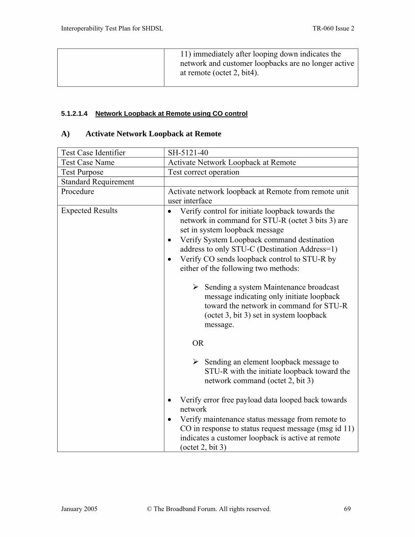
Interoperability Test Plan for SHDSL TR-060 Issue 2
January 2005 © The Broadband Forum. All rights reserved. 69
11) immediately after looping down indicates the network and customer loopbacks are no longer active at remote (octet 2, bit4).
5.1.2.1.4 Network Loopback at Remote using CO control A) Activate Network Loopback at Remote
Test Case Identifier SH-5121-40 Test Case Name Activate Network Loopback at Remote Test Purpose Test correct operation Standard Requirement Procedure Activate network loopback at Remote from remote unit
user interface Expected Results • Verify control for initiate loopback towards the
network in command for STU-R (octet 3 bits 3) are set in system loopback message
• Verify System Loopback command destination address to only STU-C (Destination Address=1)
• Verify CO sends loopback control to STU-R by either of the following two methods:
Sending a system Maintenance broadcast
message indicating only initiate loopback toward the network in command for STU-R (octet 3, bit 3) set in system loopback message.
OR
Sending an element loopback message to STU-R with the initiate loopback toward the network command (octet 2, bit 3)
• Verify error free payload data looped back towards network
• Verify maintenance status message from remote to CO in response to status request message (msg id 11) indicates a customer loopback is active at remote (octet 2, bit 3)
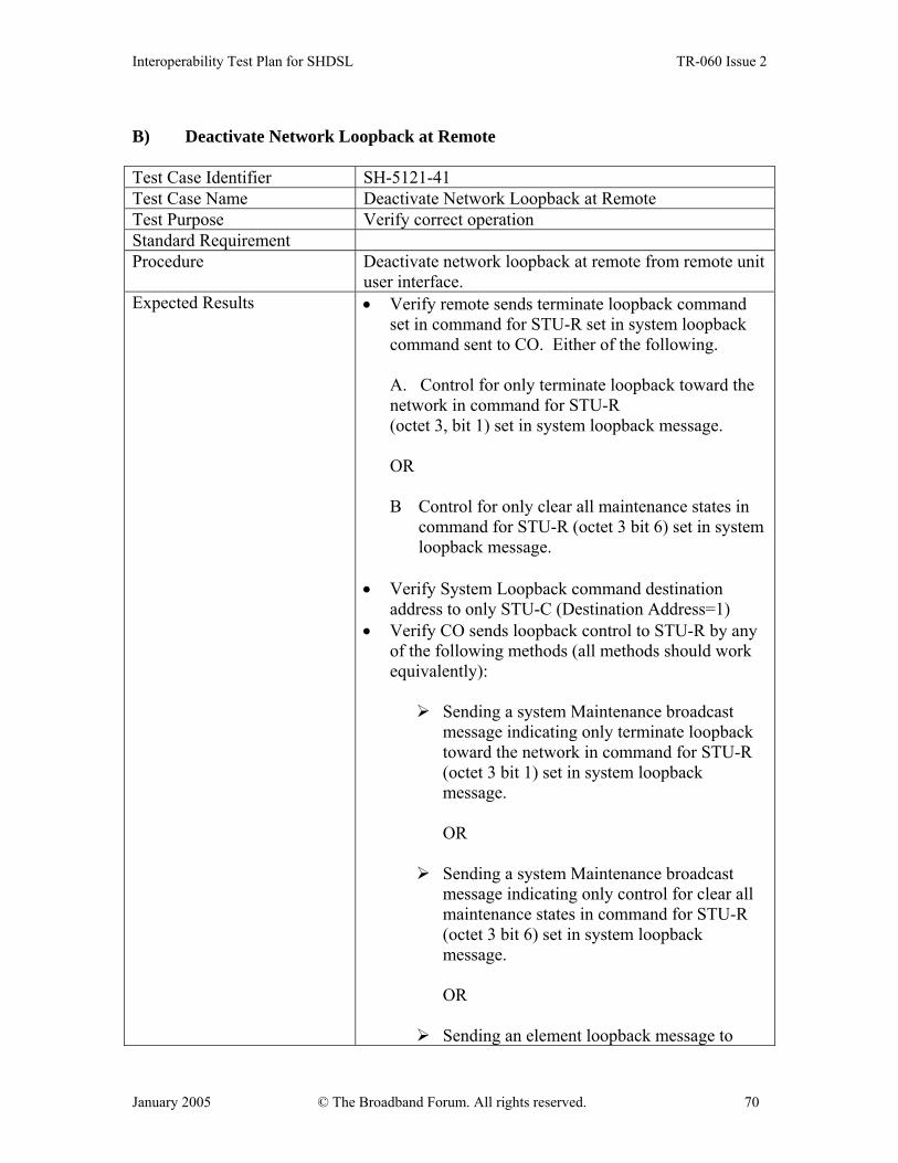
Interoperability Test Plan for SHDSL TR-060 Issue 2
January 2005 © The Broadband Forum. All rights reserved. 70
B) Deactivate Network Loopback at Remote Test Case Identifier SH-5121-41 Test Case Name Deactivate Network Loopback at Remote Test Purpose Verify correct operation Standard Requirement Procedure Deactivate network loopback at remote from remote unit
user interface. Expected Results • Verify remote sends terminate loopback command
set in command for STU-R set in system loopback command sent to CO. Either of the following.
A. Control for only terminate loopback toward the network in command for STU-R (octet 3, bit 1) set in system loopback message. OR B Control for only clear all maintenance states in
command for STU-R (octet 3 bit 6) set in system loopback message.
• Verify System Loopback command destination
address to only STU-C (Destination Address=1) • Verify CO sends loopback control to STU-R by any
of the following methods (all methods should work equivalently):
Sending a system Maintenance broadcast
message indicating only terminate loopback toward the network in command for STU-R (octet 3 bit 1) set in system loopback message.
OR
Sending a system Maintenance broadcast message indicating only control for clear all maintenance states in command for STU-R (octet 3 bit 6) set in system loopback message.
OR
Sending an element loopback message to

Interoperability Test Plan for SHDSL TR-060 Issue 2
January 2005 © The Broadband Forum. All rights reserved. 71
STU-R with the terminate loopback toward the network command (octet 2 bit 6)
OR
Sending an element loopback message to STU-R with only control for clear all maintenance states in command (octet 2 bit6)
• Verify loopback dropped and data path restored. • Verify maintenance status message from remote to
CO in response to status request message (msg id 11) immediately after looping down indicates network loopback is no longer active at remote (octet 2 bit 3).
5.1.2.1.5 Customer Loopback at Remote using CO control A) Activate Customer Loopback at Remote
Test Case Identifier SH-5121-50 Test Case Name Activate Customer Loopback at Remote Test Purpose Test correct operation Standard Requirement Procedure Activate network loopback at Remote from remote unit
user interface Expected Results • Verify o control for initiate loopback towards the
customer in command for STU-R (octet 3 bits 2) set in system loopback message
• Verify System Loopback command destination address to only STU-C (Destination Address=1)
• Verify CO sends loopback control to STU-R by either of the following two methods:
A. Sending a system Maintenance broadcast
message indicating only initiate loopback toward the customer in command for STU-R (octet 3, bit 2) set in system loopback message.
OR
B. Sending an element loopback message to STU-R with the initiate loopback toward the customer
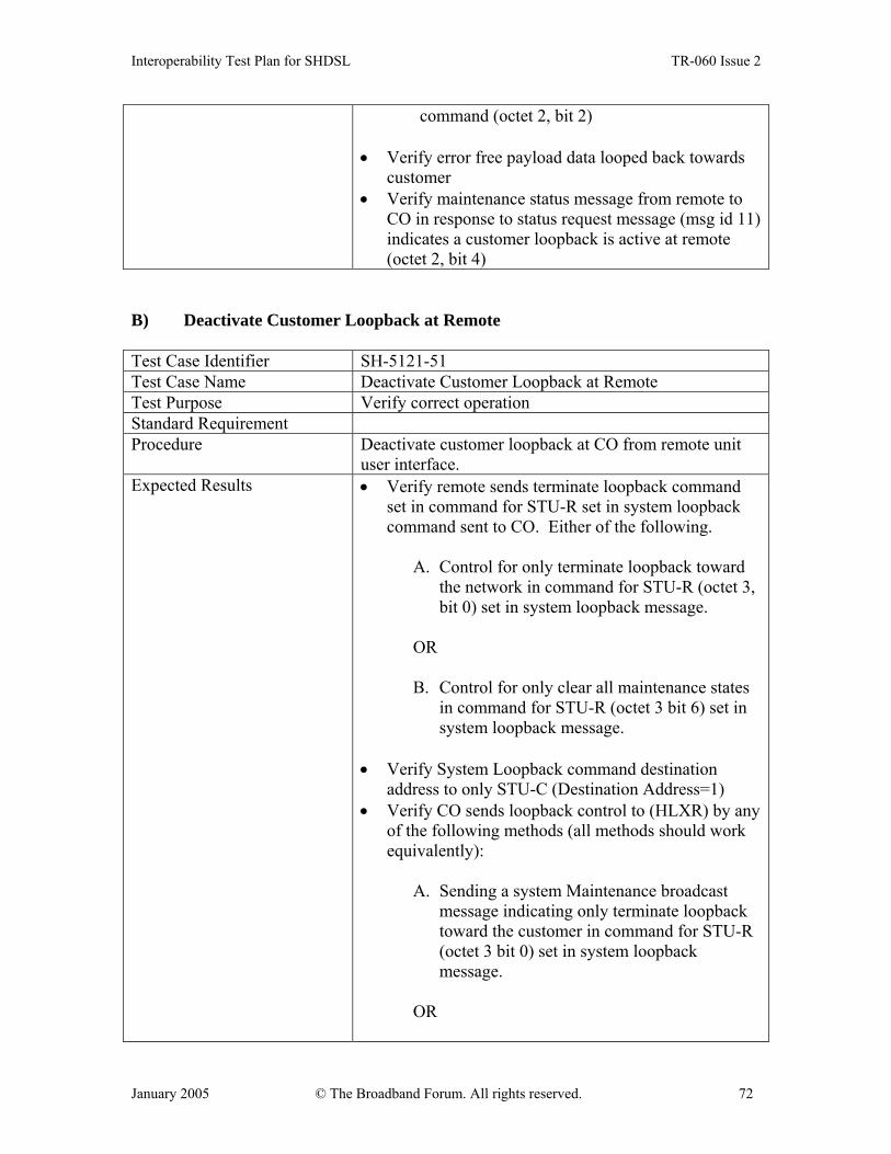
Interoperability Test Plan for SHDSL TR-060 Issue 2
January 2005 © The Broadband Forum. All rights reserved. 72
command (octet 2, bit 2)
• Verify error free payload data looped back towards customer
• Verify maintenance status message from remote to CO in response to status request message (msg id 11) indicates a customer loopback is active at remote (octet 2, bit 4)
B) Deactivate Customer Loopback at Remote
Test Case Identifier SH-5121-51 Test Case Name Deactivate Customer Loopback at Remote Test Purpose Verify correct operation Standard Requirement Procedure Deactivate customer loopback at CO from remote unit
user interface. Expected Results • Verify remote sends terminate loopback command
set in command for STU-R set in system loopback command sent to CO. Either of the following.
A. Control for only terminate loopback toward
the network in command for STU-R (octet 3, bit 0) set in system loopback message.
OR B. Control for only clear all maintenance states
in command for STU-R (octet 3 bit 6) set in system loopback message.
• Verify System Loopback command destination
address to only STU-C (Destination Address=1) • Verify CO sends loopback control to (HLXR) by any
of the following methods (all methods should work equivalently):
A. Sending a system Maintenance broadcast
message indicating only terminate loopback toward the customer in command for STU-R (octet 3 bit 0) set in system loopback message.
OR

Interoperability Test Plan for SHDSL TR-060 Issue 2
January 2005 © The Broadband Forum. All rights reserved. 73
B. Sending a system Maintenance broadcast message indicating only control for clear all maintenance states in command for STU-R (octet 3 bit 6) set in system loopback message.
OR C. Sending an element loopback message to
STU-R with the terminate loopback toward the customer command (octet 2 bit 0)
OR D. Sending an element loopback message to
STU-R with only control for all maintenance states in command (octet 2 bit 6)
• Verify loopback dropped and data path restored. • Verify maintenance status message from remote to
CO in response to status request message (msg id 11) immediately after looping down indicates a customer loopback is no longer active at remote (octet 2 bit 4).
5.1.2.1.6 Bi-directional Loopback at Remote using CO control (if supported by both ends) A) Activate Bi-directional Loopback at Remote
Test Case Identifier SH-5121-60 Test Case Name Activate Bi-directional Loopback at Remote Test Purpose Test for correct operation Standard Requirement Procedure Activate bi-directional loopback at remote from remote
unit user interface. Expected Results • Verify control for initiate loopback towards the
network and customer in command for STU-R (octet 3 bits 2&3) set in system loopback message
• Verify System Loopback command destination address to only STU-C (Destination Address=1)
• Verify CO sends loopback control to (HLXR) by either of the following two methods:
A. Sending a system Maintenance broadcast

Interoperability Test Plan for SHDSL TR-060 Issue 2
January 2005 © The Broadband Forum. All rights reserved. 74
message indicating only Initiate loopback toward the network and customer in command for STU-R (octet 3, bit 2&3) set in system loopback message. OR
B. Sending an element loopback message to STU-R with the initiate loopback toward the network and customer command (octet 2, bit 2&3)
• Verify error free payload data looped back towards
both network and customer • Verify maintenance status message from remote to
CO in response to status request message (msg id 11) indicates both network and customer loopbacks are active at remote (octet 2, bit 3&4)
• If the remote cannot support multiple loopbacks requests, it shall respond with a maintenance status message that indicates its current active loopback.
B) Deactivate Bi-directional Loopback at Remote Test Case Identifier SH-5121-61 Test Case Name Deactivate Bi-directional Loopback at Remote Test Purpose Test for correct operation Standard Requirement Procedure Deactivate bi-directional loopback at CO from remote
unit user interface. Expected Results • Verify remote sends terminate loopback command
set in command for STU-R set in system loopback command sent to CO. Either of the following.
A. Control for only terminate loopback toward the network and customer in command for STU-R (octet 3, bits 0&1) set in system loopback message.
OR
B. Control for only clear all maintenance states in command for STU-R (octet 3 bit 6) set in system loopback message.
• Verify System Loopback command destination address to only STU-C (Destination Address=1)

Interoperability Test Plan for SHDSL TR-060 Issue 2
January 2005 © The Broadband Forum. All rights reserved. 75
• Verify CO sends loopback control to (HLXR) by any of the following methods (all methods should work equivalently):
A. Sending a system Maintenance broadcast
message indicating only terminate loopback toward the customer in command for STU-R (octet 3 bit 0) set in system loopback message.
OR
B. Sending a system Maintenance broadcast
message indicating only control for clear all maintenance states in command for STU-R (octet3 bit6) set in system loopback message.
OR C. Sending an element loopback message to
STU-R with the terminate loopback toward the network command (octet 2 bits 0&1)
OR D. Sending an element loopback message to
STU-R with only control for clear all maintenance states in command (octet 2 bit 6)
• Verify loopbacks dropped and data path restored. • Verify maintenance status message from remote to CO in response to status request message (msg id 11) immediately after looping down indicates network and customer loopbacks are no longer active at remote (octet 2 bits 3&4)
5.1.2.2 Remote Control Mode: Element Loop back Message (Msg id 10) This set of tests is applicable with any STU-C when the STU-R unit implements an Element Loop back Message control to activate loop backs at other units in the system.

Interoperability Test Plan for SHDSL TR-060 Issue 2
January 2005 © The Broadband Forum. All rights reserved. 76
5.1.2.2.1 Network Loop back at CO A) Activate Network Loop back at CO
Test Case Identifier SH-5122-10 Test Case Name Activate Network Loop back at CO Test Purpose Test correct operation Standard Requirement Procedure Activate network loop back at CO from Remote Unit
user interface Expected Results • Verify control for initiate loop back toward the
network in command for STU-C (octet 2 bit 3) set in element loopback message
• Verify error free payload data looped back towards network
• Verify Element Loopback command destination address to only STU-C (Destination Address =1)
• Verify maintenance status message from CO to Remote in response to status request message (msg id 11) indicates a network loopback is active at remote (octet 2 bit 3).
B) Deactivate Network Loopback at CO
Test both methods of deactivation
Test Case Identifier SH-5122-11 Test Case Name Deactivate Network Loopback at CO Test Purpose Verify correct operation Standard Requirement Procedure Deactivate network loopback at CO from remote unit
user interface using terminate loopback toward network in element loopback message.
Expected Results • Verify only control for terminate loopback toward the network in command for STU-C (octet 2 bit 1) set in element loopback message.
• Verify Element Loopback command destination address to only STU-C (Destination Address=1)
• Verify Loopback dropped and data path restored. • Verify maintenance status message from CO to
remote in response to status request message (Msg id 11) immediately after looping down indicates a network loopback is no longer active at CO (octet 2, bit3).

Interoperability Test Plan for SHDSL TR-060 Issue 2
January 2005 © The Broadband Forum. All rights reserved. 77
Test Case Identifier SH-5122-12 Test Case Name Deactivate Network Loopback at CO Test Purpose Verify correct operation Standard Requirement Procedure Deactivate network loopback at CO from remote unit
user interface using clear all maintenance states in element loop back message.
Expected Results • Verify only control for clear all maintenance states in command for STU-C (octet 2, bit 6) set in system loopback message
• Verify Element Loopback command destination address to only STU-C (Destination Address=1)
• Verify Loopback dropped and data path restored. • Verify maintenance status message from CO to
remote in response to status request message (Msg id 11) immediately after looping down indicates a network loopback is no longer active at CO (octet 2, bit 3).
5.1.2.2.2 Customer Loopback at CO A) Activate Customer Loopback at CO
Test Case Identifier SH-5122-20 Test Case Name Activate Customer Loopback at CO Test Purpose Test correct operation Standard Requirement Procedure Activate customer loopback at CO from remote unit user
interface Expected Results • Verify only control for initiate loopback toward the
customer in command for STU-C (octet 2 bit 2) set in element loopback message
• Verify error free payload data looped back towards customer
• Verify Element Loopback command destination address to only STU-C (Destination Address=1)
• Verify maintenance status message from CO to remote in response to status request message (msg id 11) indicates a customer loopback is active at CO (octet 2 bit 4)

Interoperability Test Plan for SHDSL TR-060 Issue 2
January 2005 © The Broadband Forum. All rights reserved. 78
B) Deactivate Customer Loopback at Remote Test both methods of deactivation Test Case Identifier SH-5122-21 Test Case Name Deactivate Customer Loopback at Remote Test Purpose Verify correct operation Standard Requirement Procedure Deactivate customer loopback at CO from remote unit
user interface using terminate loopback toward customer in element loopback message.
Expected Results • Verify control for terminate loopback toward the customer in command for STU-C (octet 2 bit 0) set in element loopback message.
• Verify loopback dropped and data path restores. • Verify System Loopback command destination
address to only STU-C (Destination Address=1) • Verify maintenance status message from CO to
remote in response to status request message (Msg id 11) immediately after looping down indicates the customer loopback is no longer active at CO (octet 2, bit 3).
Test Case Identifier SH-5122-22 Test Case Name Deactivate Customer Loopback at Remote Test Purpose Verify correct operation Standard Requirement Procedure Deactivate customer loopback at CO from remote unit
user interface using clear all maintenance states in element loop back message.
Expected Results • Verify control for clear all maintenance states in command for STU-C(octet 2, bit 6) set in element loopback message
• Verify loopback dropped and data path restores. • Verify System Loopback command destination
address to only STU-C (Destination Address=1) • Verify maintenance status message from CO to
remote in response to status request message (Msg id 11) immediately after looping down indicates the customer loopback is no longer active at CO (octet 2, bit3).
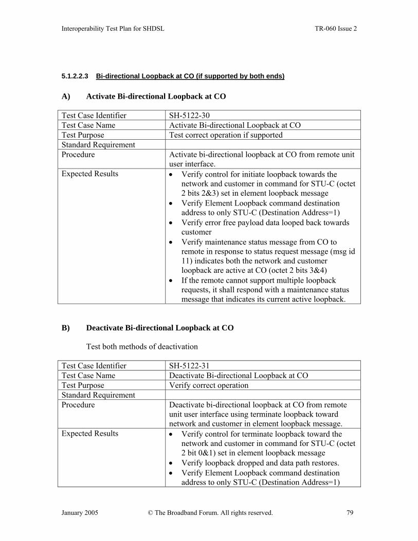
Interoperability Test Plan for SHDSL TR-060 Issue 2
January 2005 © The Broadband Forum. All rights reserved. 79
5.1.2.2.3 Bi-directional Loopback at CO (if supported by both ends) A) Activate Bi-directional Loopback at CO
Test Case Identifier SH-5122-30 Test Case Name Activate Bi-directional Loopback at CO Test Purpose Test correct operation if supported Standard Requirement Procedure Activate bi-directional loopback at CO from remote unit
user interface. Expected Results • Verify control for initiate loopback towards the
network and customer in command for STU-C (octet 2 bits 2&3) set in element loopback message
• Verify Element Loopback command destination address to only STU-C (Destination Address=1)
• Verify error free payload data looped back towards customer
• Verify maintenance status message from CO to remote in response to status request message (msg id 11) indicates both the network and customer loopback are active at CO (octet 2 bits 3&4)
• If the remote cannot support multiple loopback requests, it shall respond with a maintenance status message that indicates its current active loopback.
B) Deactivate Bi-directional Loopback at CO
Test both methods of deactivation
Test Case Identifier SH-5122-31 Test Case Name Deactivate Bi-directional Loopback at CO Test Purpose Verify correct operation Standard Requirement Procedure Deactivate bi-directional loopback at CO from remote
unit user interface using terminate loopback toward network and customer in element loopback message.
Expected Results • Verify control for terminate loopback toward the network and customer in command for STU-C (octet 2 bit 0&1) set in element loopback message
• Verify loopback dropped and data path restores. • Verify Element Loopback command destination
address to only STU-C (Destination Address=1)
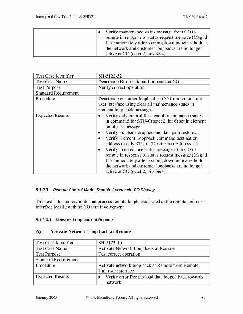
Interoperability Test Plan for SHDSL TR-060 Issue 2
January 2005 © The Broadband Forum. All rights reserved. 80
• Verify maintenance status message from CO to remote in response to status request message (Msg id 11) immediately after looping down indicates both the network and customer loopbacks are no longer active at CO (octet 2, bits 3&4).
Test Case Identifier SH-5122-32 Test Case Name Deactivate Bi-directional Loopback at CO Test Purpose Verify correct operation Standard Requirement Procedure Deactivate customer loopback at CO from remote unit
user interface using clear all maintenance states in element loop back message.
Expected Results • Verify only control for clear all maintenance states in command for STU-C(octet 2, bit 6) set in element loopback message
• Verify loopback dropped and data path restores. • Verify Element Loopback command destination
address to only STU-C (Destination Address=1) • Verify maintenance status message from CO to
remote in response to status request message (Msg id 11) immediately after looping down indicates both the network and customer loopbacks are no longer active at CO (octet 2, bits 3&4).
5.1.2.3 Remote Control Mode: Remote Loopback: CO Display This test is for remote units that process remote loopbacks issued at the remote unit user interface locally with no CO unit involvement 5.1.2.3.1 Network Loop back at Remote A) Activate Network Loop back at Remote Test Case Identifier SH-5123-10 Test Case Name Activate Network Loop back at Remote Test Purpose Test correct operation Standard Requirement Procedure Activate network loop back at Remote from Remote
Unit user interface Expected Results • Verify error free payload data looped back towards
network
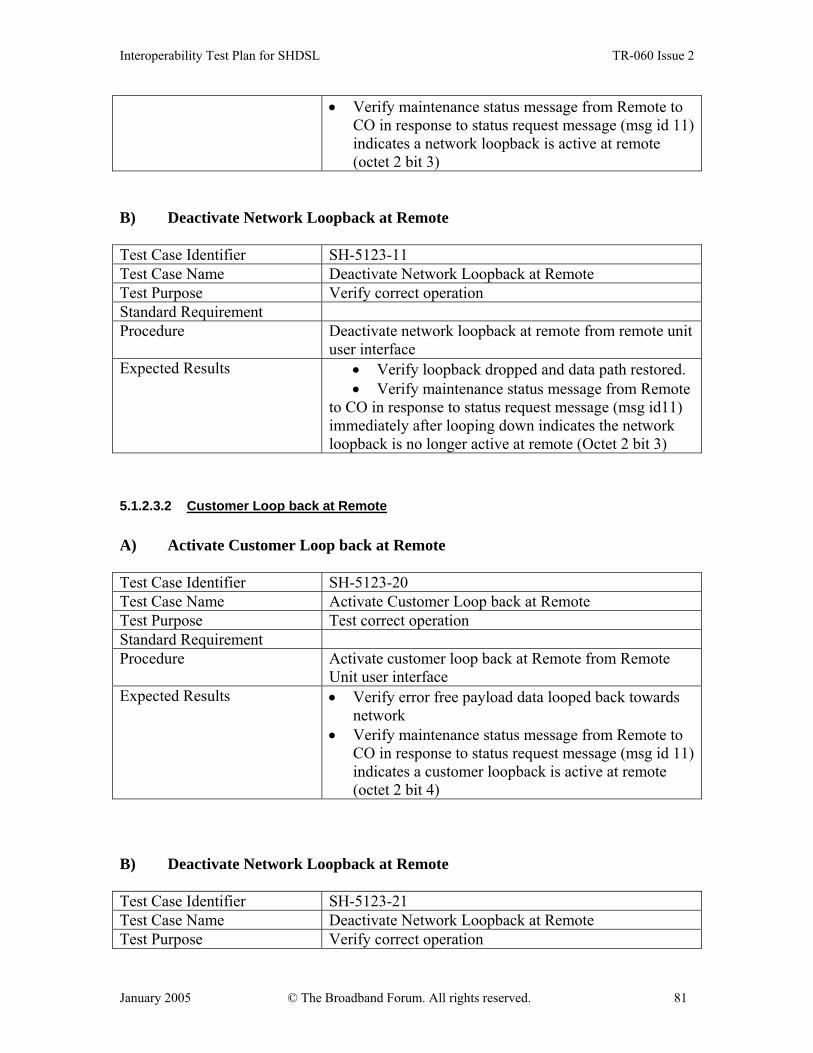
Interoperability Test Plan for SHDSL TR-060 Issue 2
January 2005 © The Broadband Forum. All rights reserved. 81
• Verify maintenance status message from Remote to CO in response to status request message (msg id 11) indicates a network loopback is active at remote (octet 2 bit 3)
B) Deactivate Network Loopback at Remote
Test Case Identifier SH-5123-11 Test Case Name Deactivate Network Loopback at Remote Test Purpose Verify correct operation Standard Requirement Procedure Deactivate network loopback at remote from remote unit
user interface Expected Results • Verify loopback dropped and data path restored.
• Verify maintenance status message from Remote to CO in response to status request message (msg id11) immediately after looping down indicates the network loopback is no longer active at remote (Octet 2 bit 3)
5.1.2.3.2 Customer Loop back at Remote A) Activate Customer Loop back at Remote
Test Case Identifier SH-5123-20 Test Case Name Activate Customer Loop back at Remote Test Purpose Test correct operation Standard Requirement Procedure Activate customer loop back at Remote from Remote
Unit user interface Expected Results • Verify error free payload data looped back towards
network • Verify maintenance status message from Remote to
CO in response to status request message (msg id 11) indicates a customer loopback is active at remote (octet 2 bit 4)
B) Deactivate Network Loopback at Remote Test Case Identifier SH-5123-21 Test Case Name Deactivate Network Loopback at Remote Test Purpose Verify correct operation

Interoperability Test Plan for SHDSL TR-060 Issue 2
January 2005 © The Broadband Forum. All rights reserved. 82
Standard Requirement Procedure Deactivate network loopback at remote from remote unit
user interface Expected Results • Verify loopback dropped and data path restored.
• Verify maintenance status message from Remote to CO in response to status request message (msg id11) immediately after looping down indicates the customer loopback is no longer active at remote (Octet 2 bit 4).
5.1.2.3.3 Bi-directional Loop back at Remote (if supported by Remote) A) Activate Bi-directional Loop back at Remote
Test Case Identifier SH-5123-30 Test Case Name Activate Bi-directional Loop back at Remote Test Purpose Test correct operation Standard Requirement Procedure Activate bi-directional loop back at Remote from
Remote Unit user interface Expected Results • Verify error free payload data looped back towards
both network and customer. • Verify maintenance status message from Remote to
CO in response to status request message (msg id 11) indicates that network and customer loopbacks are active at remote (octet 2 bits 3&4)
B) Deactivate Bi-directional Loopback at Remote
Test Case Identifier SH-5123-31 Test Case Name Deactivate Bi-directional Loopback at Remote Test Purpose Verify correct operation Standard Requirement Procedure Deactivate bi-directional loopback at remote from
remote unit user interface Expected Results • Verify loopbacks dropped and data path restored.
• Verify maintenance status message from Remote to CO in response to status request message (msg id11) immediately after looping down indicates that both loopbacks are no longer active at remote (Octet 2 bits 3&4).

Interoperability Test Plan for SHDSL TR-060 Issue 2
January 2005 © The Broadband Forum. All rights reserved. 83
5.2 EOC Messaging Tests The scope of the EOC Messaging tests will apply to STU-x devices involved in testing EOC interoperability and functionality. Testing includes verification of SHDSL synchronization and EOC compatibility, both of which are inherent to SHDSL interoperability. When 4-wire is supported, the same EOC message is required to be passed by both loops. To verify, apply the following test cases either using one in Data mode and the other disconnected or both in the data mode. Table 9.6 of G.991.2 identifies “optional initiating units”. An acceptable response to all messages initiated by the optional initiating unit is “UTC”.
5.2.1 EOC compatibility Message ID and paragraph References are from ITU-T G.991.2. EOC Messages 1 and 129 as defined in Section 9.5.5.7.1 and 9.5.5.7.2. This includes verification of:
• Discovery Probe Message • Discovery Response Message
Test Case Identifier SH-5210-10 Test Case Name EOC Discovery Messages Test Purpose Test the EOC Discovery Probe and Response messages Standard Requirement EOC Messages 1 and 129 as defined in Section 9.5.5.7.1 and
9.5.5.7.2 Procedure Send probe message and check response Expected Results • Discovery Probe Message 1 sent and Discovery
Response Message 129 should be received. • Message ID & hopcount = number of span elements
EOC Messages 2 and 130 as defined in Section 9.5.5.7.3 and 9.5.5.7.4. This includes verification of :
• Inventory Request Message • Inventory Response Message
Test Case Identifier SH-5210-20 Test Case Name EOC Inventory Messages Test Purpose Test the EOC Inventory Request and Response messages Standard Requirement EOC Messages 2 and 130 as defined in Section 9.5.5.7.3 and
9.5.5.7.4 Procedure Send request message and check response Expected Results • Verify Message ID and Inventory data received

Interoperability Test Plan for SHDSL TR-060 Issue 2
January 2005 © The Broadband Forum. All rights reserved. 84
EOC Messages 3 and 131 as defined in Section 9.5.5.7.5 and 9.5.5.7.7. This includes verification of:
• SHDSL Configuration Request Message • SHDSL Configuration Response Message
Test Case Identifier SH-5210-30 Test Case Name EOC Configuration Test Purpose Test the EOC Configuration Request and Response messages Standard Requirement EOC Messages 3 and 131 as defined in Section 9.5.5.7.5 and
9.5.5.7.7 Procedure Send request and check response Expected Results • Verify Message ID; Change SNR Margin Threshold;
Change Loop Attenuation Threshold and verify the values of the response are set to the new values, after they have been applied. If a transceiver unit is unable to comply with the request, the bit in the Compliance Octet is set and the current settings are reported.
EOC Messages 4 and 132 as defined in Section 9.5.5.6. This includes verification of:
• TBD (Application Interface Configuration) • Response Message ID 132 not defined
Test Case Identifier SH-5210-40 Test Case Name TBD Test Purpose Reserved probe and Response messages Standard Requirement EOC Messages 4 and 132 Procedure TBD Expected Results TBD EOC Messages 5 and 133 as defined in Section 9.5.5.7.6 and 9.5.5.7.8. This includes verification of:
• Loopback Timeout Configuration Request Message • Loopback Timeout Configuration Response Message
Test Case Identifier SH-5210-50 Test Case Name EOC Loopback Timeout Configuration messages Test Purpose Verify Probe and Response messages Standard Requirement EOC Messages 5 and 133 as defined in Section 9.5.5.7.6 and
9.5.5.7.8 Procedure Send probe messages and check responses Expected Results Verify response sent after the applicable configuration
changes have been made. The values of the response

Interoperability Test Plan for SHDSL TR-060 Issue 2
January 2005 © The Broadband Forum. All rights reserved. 85
shall be set to the new values, after they have been applied. If a transceiver unit is unable to comply with the request, the bit in the Compliance Octet is set and the current settings are reported. If the Config Request message was received with a Config Type of "Read-Only," then no changes are made to the current configuration and the current values are reported. Verify that the timer functions properly in the remote unit.
EOC Messages 6,7, and 134, 8 and 136 as defined in Section 9.5.5.7.16 and 9.5.5.7.17. This includes verification of:
• Virtual Terminal Connect Request Message • Virtual Terminal Disconnect Request Message • Keyboard Data Message Request • Virtual Terminal Connect Response Message • Screen Data Message Response
Test Case Identifier SH-5210-60 Test Case Name Virtual Terminal Connect/Disconnect Test Purpose Verify virtual terminal connections can be established and
disconnected Standard Requirement EOC Messages 6, 7, 134, 136 as defined in Section 9.5.5.7.16
and 9.5.5.7.17 Procedure Send messages to establish a virtual connection,
exchange keyboard messages/response, and disconnect. Expected Results • Request a connection, wait for "connect" status
response before using the connection. • The connection remains until a disconnect request is
processed or, if implemented, a timeout occurs. At least one session shall be supported by the STU-C. STU-R and SRU may silently ignore the connect request or may respond with a "no connect" status if terminal screens are not supported.
• The connect/disconnect process is necessary for handling the case where keyboard messages are received from more than one device. If a unit cannot accommodate another connect request it shall send the "no connect" response.
• The connect request message can be sent to cause a refresh of the current screen. When a connect request is accepted the "connect" response shall be transmitted, followed by screen messages with the
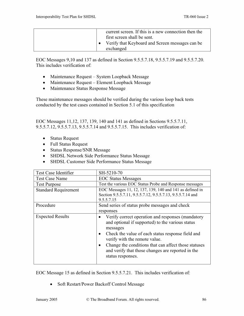
Interoperability Test Plan for SHDSL TR-060 Issue 2
January 2005 © The Broadband Forum. All rights reserved. 86
current screen. If this is a new connection then the first screen shall be sent.
• Verify that Keyboard and Screen messages can be exchanged
EOC Messages 9,10 and 137 as defined in Section 9.5.5.7.18, 9.5.5.7.19 and 9.5.5.7.20. This includes verification of:
• Maintenance Request – System Loopback Message • Maintenance Request – Element Loopback Message • Maintenance Status Response Message
These maintenance messages should be verified during the various loop back tests conducted by the test cases contained in Section 5.1 of this specification EOC Messages 11,12, 137, 139, 140 and 141 as defined in Sections 9.5.5.7.11, 9.5.5.7.12, 9.5.5.7.13, 9.5.5.7.14 and 9.5.5.7.15. This includes verification of:
• Status Request • Full Status Request • Status Response/SNR Message • SHDSL Network Side Performance Status Message • SHDSL Customer Side Performance Status Message
Test Case Identifier SH-5210-70 Test Case Name EOC Status Messages Test Purpose Test the various EOC Status Probe and Response messages Standard Requirement EOC Messages 11, 12, 137, 139, 140 and 141 as defined in
Section 9.5.5.7.11, 9.5.5.7.12, 9.5.5.7.13, 9.5.5.7.14 and 9.5.5.7.15
Procedure Send series of status probe messages and check responses
Expected Results • Verify correct operation and responses (mandatory and optional if supported) to the various status messages
• Check the value of each status response field and verify with the remote value.
• Change the conditions that can affect those statuses and verify that those changes are reported in the status responses.
EOC Message 15 as defined in Section 9.5.5.7.21. This includes verification of:
• Soft Restart/Power Backoff Control Message

Interoperability Test Plan for SHDSL TR-060 Issue 2
January 2005 © The Broadband Forum. All rights reserved. 87
Test Case Identifier SH-5210-80 Test Case Name EOC Soft Restart and Power Backoff Test Purpose Verify ability to switch receiver between default and selected
modes of power backoff Standard Requirement EOC Message 15 as defined in Section 9.5.5.7.21 Procedure Send probe message 15 and check response. If default
mode is set, PBO shall be set to the default value. Otherwise, in selected mode, PBO may be negotiated through G.994.1 to another value.
Expected Results • Verify Network side Power Backoff Setting • Verify Network side Soft Restart after 5 seconds • Verify Customer side Power Backoff Setting • Verify Customer side Soft Restart after 5 seconds
EOC Message 17 and 145 as defined in Section E.9.4.7 and E.9.4.8 This includes verification of:
• ATM Cell Status Request • ATM Cell Status Information
Test Case Identifier SH-5210-90 Test Case Name ATM Cell Status Test Purpose Test ability to get ATM OAM Cell Status information over
the EOC Standard Requirement EOC Message 17 and 145 as defined in Section E.9.4.7 and
E.9.4.8 Procedure Send ATM Cell Status Request probe message 17 and
check ATM Cell Status Information response Expected Results • Poll and verify all ATM Cell Status functions such
as Header Error Check (HEC), Loss of Cell Delineation (LCD), etc. alarms
• Poll message on clean circuit • An acceptable response for a unit which does not
support ATM is UTC EOC Messages 18 and 146 as defined in section 9.5.5.7.9 and 9.5.5.7.10. This includes verification of:
• STU-R Configuration Request – Management • Configuration Response – Management
Test Case Identifier SH-5210-100 Test Case Name STU-R Configuration Messages Test Purpose Test Configuration Message ability to enable and disable

Interoperability Test Plan for SHDSL TR-060 Issue 2
January 2005 © The Broadband Forum. All rights reserved. 88
STU-R management and Response messages Standard Requirement EOC Messages 18 and 146 as defined in Section 9.5.5.7.9 and
9.5.5.7.10 Procedure Send probe message 18 and check responses Expected Results • Verify that STU-R management flow can be
enabled and disabled. • Verify that Config Response – Management
message is sent to acknowledge the Config Request – Management message. Check that messages 2-12 are not initiated by STU-R after this message exchange.
EOC Message 144 as defined in Section 9.5.5.7.26. This includes verification of:
• Generic Unable to Comply (UTC) Response to a message that the unit is not able to process.
• Check that an indication is given of the Message ID of the request message. Test Case Identifier SH-5210-110 Test Case Name EOC Generic Unable to Comply (UTC) Message Test Purpose Test the EOC ability to send a message indicating it is unable
to comply with a request Standard Requirement EOC Messages 144 as defined in Section 9.5.5.7.26 Procedure Send a probe message that the far end can not comply
with. Expected Results Verify receipt of UTC message Reference table for the above messages are given below in Table 14. The full set of EOC Message IDs is contained in Table 9-6/G.991.2.
TABLE 14: EOC MESSAGES
Probe Message Verify Response Message ID
Type ID Discovery Probe 1 Hopcount = the number of span
elements 129
Inventory Request 2 Inventory data received 130 Configuration Request 3 • Change SNR Margin
Threshold • Change Loop
131

Interoperability Test Plan for SHDSL TR-060 Issue 2
January 2005 © The Broadband Forum. All rights reserved. 89
Attenuation Threshold Application Interface Configuration
4 • Future use TBD 132
Configuration Request – Loopback Timeout
5 Configure Time/Date/LBTO • Set LBTO to 0 (no timeout) • Change LBTO to other settings • Set Date • Set Time
133
Virtual Terminal Connect Request 6 Connect Virtual Terminal • Connect VT from STU-C • Connect VT from STU-R
134
Virtual Terminal Disconnect Request
7 Disconnect Virtual Terminal
Keyboard Data Message 8 Accept keyboard messages while in Virtual Terminal session
136
Maintenance Request – System Loopback
9 Initiate loopbacks; verify screen reflects properly on both units • STU-C loopback to network • STU-C loopback to customer • STU-R loopback to network • STU-R loopback to customer • STU-R bilateral loopback • Loopdown all from STU-C • Loopdown all from STU-R
137
Maintenance Request – Element Loopback
10 Initiate loopbacks; verify screen reflects properly on both units • STU-C loopback to network • STU-C loopback to customer • STU-R loopback to network • STU-R loopback to customer • STU-R bilateral loopback • Loopdown all from STU-C • Loopdown all from STU-R
137
Status Request 11 Poll for alarms and performance status • Poll message on clean circuit • Poll message with SHDSL
faults
SNR Margin alarm Loop Attenuation alarm DC Continuity Fault SHDSL LOSW defect ES Count SES Count UAS Count Device Fault Power Backoff
139 140, 141

Interoperability Test Plan for SHDSL TR-060 Issue 2
January 2005 © The Broadband Forum. All rights reserved. 90
Full Status Request 12 Poll full status with clean circuit 137, 140-141 Soft restart/Power backoff disable request
15 Verify restart after 5 seconds
ATM Cell Status Request 17 ATM Cell Status Information 145 STU-R Configuration Request – Management
18 Configuration Response – Management
146
Unable to Comply (UTC) 144
5.3 Virtual Terminal Disconnect Tests Interoperability issues on virtual terminal disconnection were identified due to different disconnect procedures under different applications. We may choose to use some of the tests that have been incorporated into HDSL2 Interoperability.
6 SHDSL CPE Application Level Testing SHDSL CPE products for broadband access may include bridging, routing or other features like Circuit Emulation Service (CES), Frame Relay over ATM (FRF.5 and FRF.8) and VoDSL. Interoperability requires these services to be interoperable as well. Additionally the performance of those additional features should cover operation at the highest possible line speeds. The following proposes some basic interoperability and performance tests for routing, bridging, and CES enabled SHDSL CPEs with DSLAMs. The tests might equally be used for other symmetric DSL solutions.
6.1 Required test equipment The Table 15 summarizes the required test equipment for the interoperability and performance tests described in this document.
TABLE 15: REQUIRED TEST EQUIPMENT Test equipment Quantity Icon Comments Device under test
2 DUT
DSLAM 1 DSLAM Includes a SHDSL card and an uplink card. The uplink matches the interface type on the BAS. If BAS functions are included in the DSLAM, a LAN interface is available.
Broadband Access Server
1 BAS The BAS has an interface matching the DSLAM uplink interface type. It has as well a LAN interface. It can terminate RFC2684, PPPoA and
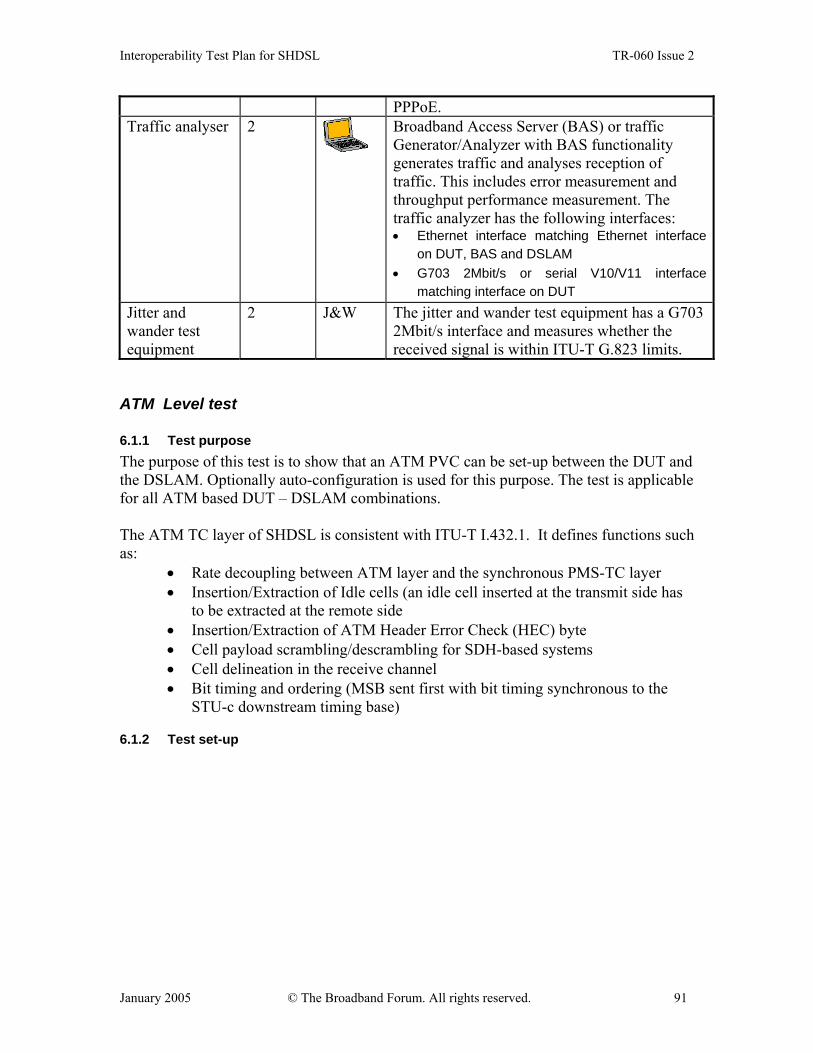
Interoperability Test Plan for SHDSL TR-060 Issue 2
January 2005 © The Broadband Forum. All rights reserved. 91
PPPoE. Traffic analyser 2
Broadband Access Server (BAS) or traffic Generator/Analyzer with BAS functionality generates traffic and analyses reception of traffic. This includes error measurement and throughput performance measurement. The traffic analyzer has the following interfaces: • Ethernet interface matching Ethernet interface
on DUT, BAS and DSLAM • G703 2Mbit/s or serial V10/V11 interface
matching interface on DUT Jitter and wander test equipment
2 J&W The jitter and wander test equipment has a G703 2Mbit/s interface and measures whether the received signal is within ITU-T G.823 limits.
ATM Level test
6.1.1 Test purpose The purpose of this test is to show that an ATM PVC can be set-up between the DUT and the DSLAM. Optionally auto-configuration is used for this purpose. The test is applicable for all ATM based DUT – DSLAM combinations. The ATM TC layer of SHDSL is consistent with ITU-T I.432.1. It defines functions such as:
• Rate decoupling between ATM layer and the synchronous PMS-TC layer • Insertion/Extraction of Idle cells (an idle cell inserted at the transmit side has
to be extracted at the remote side • Insertion/Extraction of ATM Header Error Check (HEC) byte • Cell payload scrambling/descrambling for SDH-based systems • Cell delineation in the receive channel • Bit timing and ordering (MSB sent first with bit timing synchronous to the
STU-c downstream timing base)
6.1.2 Test set-up
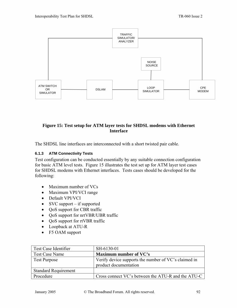
Interoperability Test Plan for SHDSL TR-060 Issue 2
January 2005 © The Broadband Forum. All rights reserved. 92
DSLAM
NOISESOURCE
LOOPSIMULATOR
CPEMODEM
ATM SWITCHOR
SIMULATOR
TRAFFICSIMULATOR/ANALYZER
Figure 15: Test setup for ATM layer tests for SHDSL modems with Ethernet Interface
The SHDSL line interfaces are interconnected with a short twisted pair cable.
6.1.3 ATM Connectivity Tests Test configuration can be conducted essentially by any suitable connection configuration for basic ATM level tests. Figure 15 illustrates the test set up for ATM layer test cases for SHDSL modems with Ethernet interfaces. Tests cases should be developed for the following:
• Maximum number of VCs • Maximum VPI/VCI range • Default VPI/VCI • SVC support – if supported • QoS support for CBR traffic • QoS support for nrtVBR/UBR traffic • QoS support for rtVBR traffic • Loopback at ATU-R • F5 OAM support
Test Case Identifier SH-6130-01 Test Case Name Maximum number of VC’s Test Purpose Verify device supports the number of VC’s claimed in
product documentation Standard Requirement Procedure Cross connect VC’s between the ATU-R and the ATU-C

Interoperability Test Plan for SHDSL TR-060 Issue 2
January 2005 © The Broadband Forum. All rights reserved. 93
until 16 VC’s are successfully configured or until the system will not accept any more, which ever is less.
Additional Information Test Configuration using Figure 15 The ATM switch or simulator may be removed if the traffic simulator/analyzer is capable of terminating ATM traffic directly from the DSLAM.
Expected Results Maximum number of VC’s is the same as that published in the ATU-R or DSLAM documentation, whichever is less.
Test Case Identifier SH-6130-02 Test Case Name Maximum VPI/VCI Range Test Purpose Verify VPI/VCI support within published range Standard Requirement Procedure Configure VPI/VCI just within the published range, and
just outside the published range. Additional Information Test Configuration using Figure 15
The ATM switch or simulator may be removed if the traffic simulator/analyzer is capable of terminating ATM traffic directly from the DSLAM.
Expected Results Verify that capability to choose VPI/VCI falls within published range for the DSLAM or the ATU-R modem, whichever is more restrictive.
Test Case Identifier SH-6130-03 Test Case Name Default VCI/VPI Test Purpose Test for proper default value (default VP/VC is 0/35) Standard Requirement Procedure With the ATU-R/CPE in its default configuration, cross
connect a circuit in this default VPI/VCI range and pass cells over the connection.
Additional Information Test Configuration using Figure 15 The ATM switch or simulator may be removed if the traffic simulator/analyzer is capable of terminating ATM traffic directly from the DSLAM.
Expected Results Cells must be passed across the connection using the default VPI/VCI value and those from the CPE General Information table.
Test Case Identifier SH-6130-04 Test Case Name SVC Support (optional, if supported)
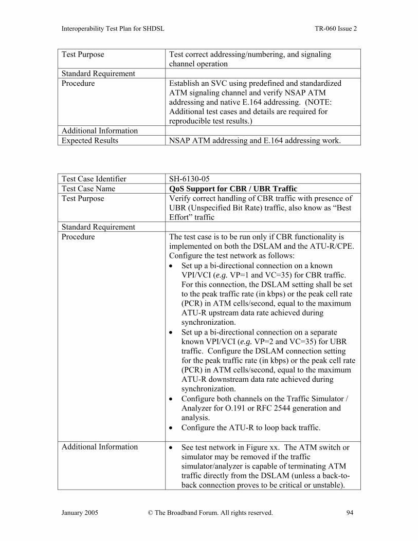
Interoperability Test Plan for SHDSL TR-060 Issue 2
January 2005 © The Broadband Forum. All rights reserved. 94
Test Purpose Test correct addressing/numbering, and signaling channel operation
Standard Requirement Procedure Establish an SVC using predefined and standardized
ATM signaling channel and verify NSAP ATM addressing and native E.164 addressing. (NOTE: Additional test cases and details are required for reproducible test results.)
Additional Information Expected Results NSAP ATM addressing and E.164 addressing work. Test Case Identifier SH-6130-05 Test Case Name QoS Support for CBR / UBR Traffic Test Purpose Verify correct handling of CBR traffic with presence of
UBR (Unspecified Bit Rate) traffic, also know as “Best Effort” traffic
Standard Requirement Procedure The test case is to be run only if CBR functionality is
implemented on both the DSLAM and the ATU-R/CPE. Configure the test network as follows: • Set up a bi-directional connection on a known
VPI/VCI (e.g. VP=1 and VC=35) for CBR traffic. For this connection, the DSLAM setting shall be set to the peak traffic rate (in kbps) or the peak cell rate (PCR) in ATM cells/second, equal to the maximum ATU-R upstream data rate achieved during synchronization.
• Set up a bi-directional connection on a separate known VPI/VCI (e.g. VP=2 and VC=35) for UBR traffic. Configure the DSLAM connection setting for the peak traffic rate (in kbps) or the peak cell rate (PCR) in ATM cells/second, equal to the maximum ATU-R downstream data rate achieved during synchronization.
• Configure both channels on the Traffic Simulator / Analyzer for O.191 or RFC 2544 generation and analysis.
• Configure the ATU-R to loop back traffic.
Additional Information • See test network in Figure xx. The ATM switch or simulator may be removed if the traffic simulator/analyzer is capable of terminating ATM traffic directly from the DSLAM (unless a back-to-back connection proves to be critical or unstable).

Interoperability Test Plan for SHDSL TR-060 Issue 2
January 2005 © The Broadband Forum. All rights reserved. 95
• The loop simulator may be bypassed. • The noise generator may be removed.
Expected Results O.191 or RFC 2544 analysis shall show that only UBR traffic is discarded and that all of the CBR traffic is delivered, if UBR and CBR are implemented.
Test Case Identifier SH-6130-06 Test Case Name QoS Support for rt-VBR / UBR Traffic Test Purpose Verify QoS operation for real time-Variable Bit Rate
(rt-VBR) in presence of UBR traffic Standard Requirement Procedure This test should be performed only if rt-VBR
functionality is provided on both the DSLAM and ATU-R/CPE. Configure the test network as follows: • Set up a bi-directional connection on a known
VPI/VCI (e.g. VP=1 and VC=35) for rt-VBR traffic. Set the peak traffic rate equal to the maximum ATU-R upstream data rate and the sustained traffic rate equal to half the maximum ATU-R upstream data rate.
• Set up a bi-directional connection on a separate known VPI/VCI (e.g. VP=2 and VC=35) for UBR traffic. Set the traffic rate equal to the maximum ATU-R downstream data rate.
• Configure both channels on the Traffic Simulator / Analyzer for O.191 or RFC 2544 generation and analysis.
• Configure the ATU-R to loop back traffic.
Additional Information Expected Results O.191 or RFC 2544 analysis shall show that all of the
cells in the rt-VBR data stream are delivered, if rt-VBR and UBR are implemented. Additionally, a portion of the UBR data stream shall be delivered.
Test Case Identifier SH-6130-07 Test Case Name QoS Support for nrt-VBR / UBR Traffic Test Purpose Confirm correct QoS functionality for non-real time
VBR (nrt-VBR) traffic type Standard Requirement Procedure The following procedure should be used if QoS support
is provided for nrt-VBR and UBR traffic. Configure the
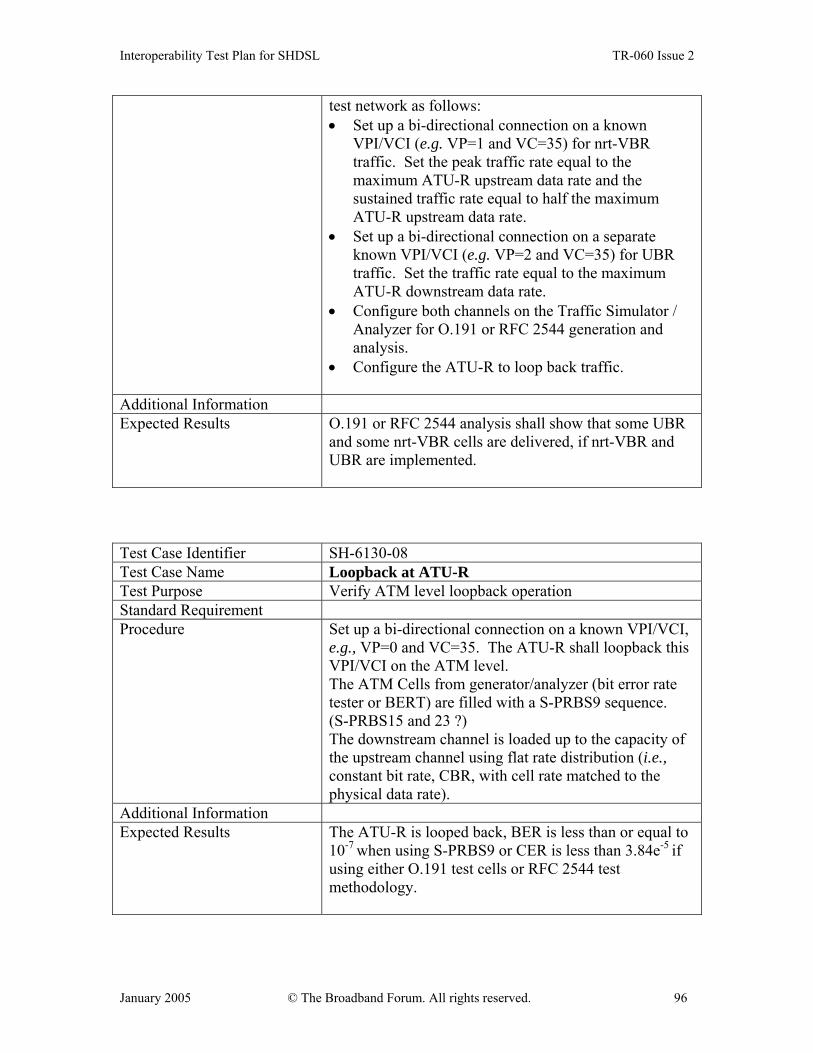
Interoperability Test Plan for SHDSL TR-060 Issue 2
January 2005 © The Broadband Forum. All rights reserved. 96
test network as follows: • Set up a bi-directional connection on a known
VPI/VCI (e.g. VP=1 and VC=35) for nrt-VBR traffic. Set the peak traffic rate equal to the maximum ATU-R upstream data rate and the sustained traffic rate equal to half the maximum ATU-R upstream data rate.
• Set up a bi-directional connection on a separate known VPI/VCI (e.g. VP=2 and VC=35) for UBR traffic. Set the traffic rate equal to the maximum ATU-R downstream data rate.
• Configure both channels on the Traffic Simulator / Analyzer for O.191 or RFC 2544 generation and analysis.
• Configure the ATU-R to loop back traffic.
Additional Information Expected Results O.191 or RFC 2544 analysis shall show that some UBR
and some nrt-VBR cells are delivered, if nrt-VBR and UBR are implemented.
Test Case Identifier SH-6130-08 Test Case Name Loopback at ATU-R Test Purpose Verify ATM level loopback operation Standard Requirement Procedure Set up a bi-directional connection on a known VPI/VCI,
e.g., VP=0 and VC=35. The ATU-R shall loopback this VPI/VCI on the ATM level. The ATM Cells from generator/analyzer (bit error rate tester or BERT) are filled with a S-PRBS9 sequence. (S-PRBS15 and 23 ?) The downstream channel is loaded up to the capacity of the upstream channel using flat rate distribution (i.e., constant bit rate, CBR, with cell rate matched to the physical data rate).
Additional Information Expected Results The ATU-R is looped back, BER is less than or equal to
10-7 when using S-PRBS9 or CER is less than 3.84e-5 if using either O.191 test cells or RFC 2544 test methodology.

Interoperability Test Plan for SHDSL TR-060 Issue 2
January 2005 © The Broadband Forum. All rights reserved. 97
Test Case Identifier SH-6130-09 Test Case Name F5 OAM Support Test Purpose Verify that the F5 OAM capability functions correctly Standard Requirement Procedure • Configure the test network for a bi-directional
connection on a known VPI/VCI (e.g. VP=0 and VC=35).
• Send an F5 OAM segment loopback cell from the network to the CPE/ATU-R.
• The OAM F5 Segment loopback request (loopback indication field =1) should specify the OAM loopback of the DSLAM under test in the Loopback Location Identification field (LLID).
Additional Information Expected Results Confirm that a response cell is received from the
DSLAM.
6.1.4 ATM Interoperability Test description If both DSLAM and DUT support auto-configuration according to The Broadband Forum Technical Report TR-037, an ATM PVC is configured on the DSLAM. If at least one of the DSLAM and DUT do not support auto-configuration, a ATM PVC is configured on both DSLAM and DUT. The test reports whether the ATM PVC comes up.
6.2 Interoperability test for SHDSL bridges and routers
6.2.1 Test purpose The purpose of this test is to show that a SHDSL bridge or router is interoperable with a DSLAM / BAS combination. Interoperability can be proven in bridge and routing modes with different encapsulation methods like RFC2684, PPPoA and PPPoEoA and with different multiplexing methods VC muxed or LLC muxed.
6.2.2 Test set-up
Figure 16: Interoperability test set-up for SHDSL bridges and routers

Interoperability Test Plan for SHDSL TR-060 Issue 2
January 2005 © The Broadband Forum. All rights reserved. 98
The test set-up shown in Figure 16 includes a BAS in the test set-up. If the DSLAM includes BAS functionality, the BAS can be omitted and the DSLAM is directly linked to the traffic analyzer. The SHDSL line interfaces are interconnected with a short twisted pair cable.
6.2.3 Test description The following basic series of tests can be performed depending on the support by DUT and DSLAM/BAS: Test No. SH6230
DUT acts as a …
ATM line encapsulation is … VC multiplexing is …
.1 Bridge RFC2684 LLC
.2 Bridge RFC2684 VC
.3 Bridge PPPoA (RFC2364) LLC
.4 Bridge PPPoA (RFC2364) VC
.5 Router RFC2684 LLC
.6 Router RFC2684 VC
.7 Router PPPoA (RFC2364) LLC
.8 Router PPPoA (RFC2364) VC
.9 Router PPPoE (RFC2516 and RFC2684)
LLC
.10 Router PPPoE (RFC2516 and RFC2684)
VC
In the tests with PPPoE, the PPPoE session is initiated on the router. Per executed test, it is reported whether LAN traffic can be sent between the traffic generators or not. Test Case Identifier SH-6231-10 Test Case Name PPPoE Test Purpose Verify PPPoE end-to-end connectivity Standard Requirement Procedure Terminate PPPoE session, and verify connectivity by
passing traffic over this PPPoE session. Additional Information Expected Results Transmitted packets are received. Test Case Identifier SH-6231-20 Test Case Name PPPoA Test Purpose Verify PPPoA end-to-end connectivity Standard Requirement

Interoperability Test Plan for SHDSL TR-060 Issue 2
January 2005 © The Broadband Forum. All rights reserved. 99
Procedure Terminate PPPoA session and verify connectivity by passing traffic over the PPPoA session.
Additional Information Expected Results Transmitted packets are received
6.3 Performance test for SHDSL bridges and routers
6.3.1 Test purpose The purpose of this test is to measure the bridging and routing forwarding performance of the DUT.
6.3.2 Minimum requirements The DSLAM can switch ATM PVCs between different DSL lines. It supports as well the maximum line speed available on the DUTs on its SHDSL line interface. The traffic generators have sufficient performance to send, receive and analyze 64 byte IP packets between each other over the LAN at the maximum rate on the SHDSL line divided by 512 bps (64B x 8 bits/B). This exceeds the maximum forwarding rate possible over the SHDSL lines, since encapsulation overhead is not counted.
6.3.3 Test set-up
Figure 17: Performance test set-up for SHDSL bridges and routers
The SHDSL line interfaces are interconnected with a short twisted pair cable at the maximum available line speed, supported on the DUT. The DSLAM is configured to switch the data between its 2 SHDSL line interfaces.
6.3.4 Test description One traffic analyzer sends a flat IP ping request with a packet size of 64 bytes to the other traffic analyzer. Flat ping means that ping requests are sent without waiting for the reply of the previous ping until K pings are not answered. K is the window size and is set for this test at 100 packets.

Interoperability Test Plan for SHDSL TR-060 Issue 2
January 2005 © The Broadband Forum. All rights reserved. 100
Over a period of 5 minutes, the total number of correctly received ping packets is measured. The forwarding rate is reported in packets per second as this value divided by 150 (300 seconds / 2 packets (ping request and ping reply)). This series of tests are done for the following combinations of routing/bridging, encapsulation and VC multiplexing: Test No. SH6340
DUT acts as a …
ATM line encapsulation is … VC multiplexing is …
.1 Bridge RFC2684 LLC
.2 Bridge RFC2684 VC
.3 Router RFC2684 LLC
.4 Router RFC2684 VC Test Case Identifier SH-6340-05 Test Case Name RFC2684 end-to-end connectivity Test Purpose Verify IP routing/bridging Standard Requirement Procedure Configure the test environment including the ATU-R
and a computer so that the ATU-R/CPE Ethernet port terminates a bridge section. The second termination of the bridge section should be implemented at an appropriate device within the testing environment (e.g., DSLAM, PoP). Pass IP packets over the complete bridge section and verify the proper reception at the destination (e.g., PoP, Host PC).
Additional Information Expected Results Transmitted packets are received
6.4 Interoperability test for SHDSL CPEs with CES capabilities
6.4.1 Test purpose The purpose of this test is to show that the DUT can be used for leased line services over an ATM network with DSLAMs as used in the test. The test focuses in particular on Circuit Emulation Service (CES) for E1 Nx64Kbit/s (fractional E1) and unstructured E1 (2.048Mbit/s) services as defined in ATM Forum “Circuit Emulation Service Interoperability Specification Version 2.0” af-vtoa-0078.000. Interoperability issues are CBR support, network clock forwarding and jitter transfer. Asynchronous clocking mode with adaptive clock recovery is not included in the tests, since this clocking mode does not require any clocking information from the network.

Interoperability Test Plan for SHDSL TR-060 Issue 2
January 2005 © The Broadband Forum. All rights reserved. 101
6.4.2 Minimum requirements The DSLAM can switch ATM PVCs between different DSL lines.
6.4.3 Test series set-up 1
Figure 18: Interoperability test set-up for SHDSL CPEs with CES capabilities The SHDSL line interfaces are interconnected with a short twisted pair cable at the maximum available line speed, supported on the DUT. The DSLAM is configured to switch the data between its 2 SHDSL line interfaces.
6.4.4 Test Series 1 description The first series of tests checks whether circuit data can be transported error-free over the ATM network. Tests can be performed in E1 Nx64K mode with synchronous clocking and G703 or serial interface types depending on supported interface types on the DUT. Serial interface types may include V35, V36, X21 and RS530 interfaces. Tests in unstructured E1 mode can be performed with different clocking modes again with G703 or serial interface types. Test No. SH6440
Clocking mode Service
.1 Synchronous E1 Nx64K on G703 2Mbit/s interface, time slots 0 through 3 and 16 are sent over the line.
.2 synchronous E1 Nx64K on G703 2Mbit/s interface, time slots 0 through 30 are sent over the line.
.3 synchronous Nx64K serial interface (V10/V11) at 256Kbit/s
.4 synchronous Nx64K serial interface (V10/V11) at 1984Kbit/s
.5 synchronous unstructured E1 on G703 2Mbit/s interface
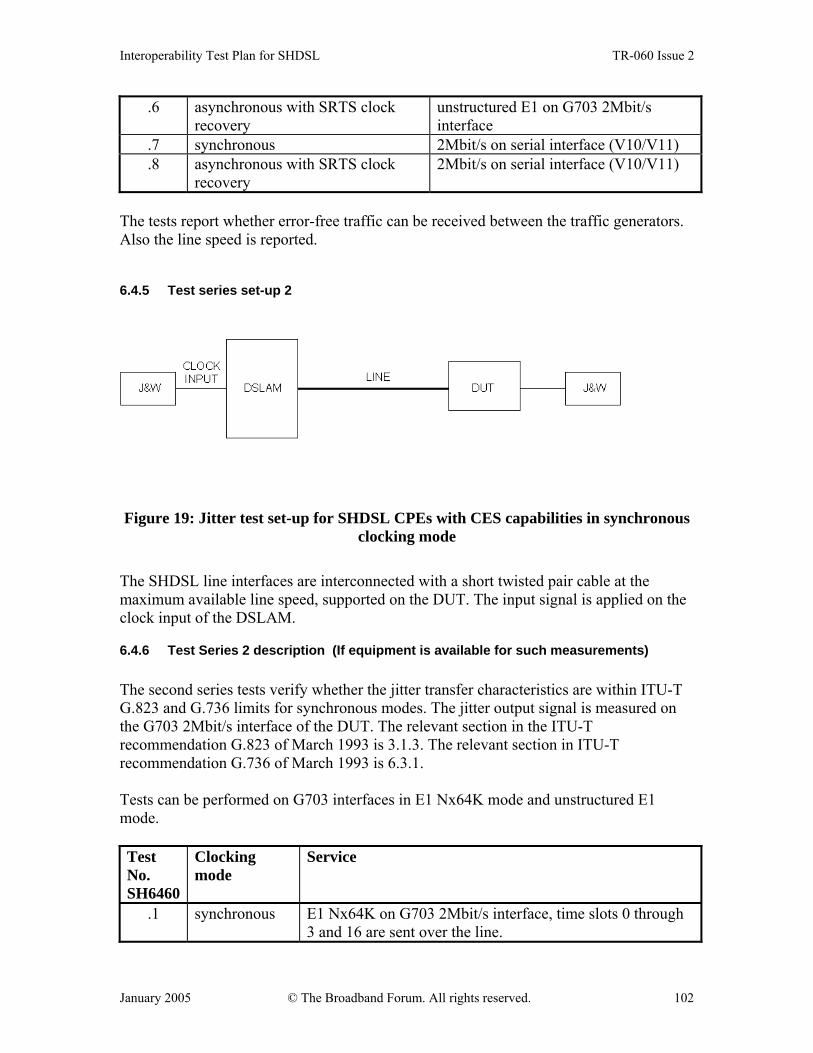
Interoperability Test Plan for SHDSL TR-060 Issue 2
January 2005 © The Broadband Forum. All rights reserved. 102
.6 asynchronous with SRTS clock recovery
unstructured E1 on G703 2Mbit/s interface
.7 synchronous 2Mbit/s on serial interface (V10/V11)
.8 asynchronous with SRTS clock recovery
2Mbit/s on serial interface (V10/V11)
The tests report whether error-free traffic can be received between the traffic generators. Also the line speed is reported.
6.4.5 Test series set-up 2
Figure 19: Jitter test set-up for SHDSL CPEs with CES capabilities in synchronous clocking mode
The SHDSL line interfaces are interconnected with a short twisted pair cable at the maximum available line speed, supported on the DUT. The input signal is applied on the clock input of the DSLAM.
6.4.6 Test Series 2 description (If equipment is available for such measurements) The second series tests verify whether the jitter transfer characteristics are within ITU-T G.823 and G.736 limits for synchronous modes. The jitter output signal is measured on the G703 2Mbit/s interface of the DUT. The relevant section in the ITU-T recommendation G.823 of March 1993 is 3.1.3. The relevant section in ITU-T recommendation G.736 of March 1993 is 6.3.1. Tests can be performed on G703 interfaces in E1 Nx64K mode and unstructured E1 mode. Test No. SH6460
Clocking mode
Service
.1 synchronous E1 Nx64K on G703 2Mbit/s interface, time slots 0 through 3 and 16 are sent over the line.

Interoperability Test Plan for SHDSL TR-060 Issue 2
January 2005 © The Broadband Forum. All rights reserved. 103
.2 synchronous unstructured E1 on G703 2Mbit/s interface The tests report the jitter transfer function and whether it is within the limits defined in ITU-T G.736.
6.4.7 Test set-up 3
Figure 20: Jitter test set-up for SHDSL CPEs with CES capabilities in asynchronous clocking mode.
The SHDSL line interfaces are interconnected with a short twisted pair cable at the maximum available line speed, supported on the DUT. The DSLAM is configured to switch the data between its 2 SHDSL line interfaces. The input jitter signal is applied on a G703 2Mbit/s interface of the first DUT.
6.4.8 Test 3 description The third test verifies whether the jitter transfer characteristics are within ITU-T G.823 and G.736 limits in asynchronous clocking mode with SRTS clock recovery. The output jitter is measured on the G703 2Mbit/s interface of the second DUT. The relevant section in the ITU-T recommendation G.823 of March 1993 is 3.1.3. The relevant section in ITU-T recommendation G.736 of March 1993 is 6.3.1. Test No. SH6480
Clocking mode Service
.1 Asynchronous with SRTS clock recovery
Unstructured E1 on G703 2Mbit/s interface
The tests report the jitter transfer function and whether it is within the limits defined in ITU-T G.736. End of specification.