Embed Size (px)
Citation preview
Interpretation and Visualization of C/C++ Data Structures
Submitted in partial fulfilment of the requirements of the
BACHELOR OF SCIENCE HONOURS DEGREE IN COMPUTER SCIENCE
at
RHODES UNIVERSITY
by
DYLAN VAN DER MERWE
November 2008

ii
Abstract
Software visualization systems in 2D, 3D and immersive environments have been incorporated in numerous
fields such as software evolution, education, security and data mining. A simple C-like language has been
designed for this project to facilitate the teaching and learning of programming concepts, such as memory
management and data structures. An Integrated Development Environment (IDE) has been developed that
includes a parser, interpreter and Visualizer within which the user may experiment, demonstrate, correct
errors and learn. As directed by the source code, the Visualizer draws variables contained on the interpreter
heap and stack as contiguous blocks of memory with which the user can interact. By utilizing a visual
system to build an immersive application for novice C/C++ programmers to learn new programming
concepts and skills, students obtain an increased vocabulary of programming terms as well as increased
engagement in the material.

iii
Acknowledgements
I would like to thank my supervisor, Dr Karen Bradshaw, for her support and encouragement throughout the
year.
Many thanks to my family and friends for everything they have done to help me reach this point in my life.
A special thanks to Phillip Foulkes who spent countless hours debating with me, listening to my ideas and
supporting me while continuing to be a good friend.
I acknowledge the financial and technical support of this project of Telkom SA, Comverse SA, OpenVoice,
Stortech, Tellabs, Amatole, Mars Technologies, Bright Ideas Projects 39 and THRIP through the Telkom
Centre of Excellence at Rhodes University.
iv
Table of Contents
Abstract .............................................................................................................................................................. ii
Acknowledgements .......................................................................................................................................... iii
Table of Contents .............................................................................................................................................. iv
List of Figures ................................................................................................................................................... vi
List of Tables ................................................................................................................................................... vii
1 Introduction ................................................................................................................................................ 1
1.1 Design and Implementation Considerations ....................................................................................... 1
1.2 Expected Output .................................................................................................................................. 2
1.3 Summary of Chapters .......................................................................................................................... 3
2 Literature Survey ....................................................................................................................................... 4
2.1 Software Visualization ........................................................................................................................ 4
2.2 2D and 3D Visualization ..................................................................................................................... 5
2.3 Virtual Environments .......................................................................................................................... 5
2.4 Metaphors ............................................................................................................................................ 6
2.5 Other Applications of SVs .................................................................................................................. 7
2.5.1 Software Evolution ...................................................................................................................... 7
2.5.2 Software Security ......................................................................................................................... 7
2.5.3 Data Mining ................................................................................................................................. 7
2.6 Student Engagement ............................................................................................................................ 7
2.7 Algorithms and Software Engineering Education ............................................................................... 8
2.8 Pointers ................................................................................................................................................ 8
2.9 Complexity .......................................................................................................................................... 9
2.10 Related Work ................................................................................................................................. 10
3 The Translator and Grammar ................................................................................................................... 12
3.1 Background of Translators ................................................................................................................ 12
3.1.1 Translation Phases ..................................................................................................................... 12
3.1.2 The Front End ............................................................................................................................ 13
3.1.3 The Back End ............................................................................................................................. 14

v
3.1.4 Top-Down Recursive Parsing .................................................................................................... 15
3.1.5 Available Parsing Tools ............................................................................................................. 16
3.2 The CMinor Language ...................................................................................................................... 17
3.2.1 CMinor Supports ........................................................................................................................ 18
3.2.2 CMinor does not Support ........................................................................................................... 18
3.3 Developing the Grammar .................................................................................................................. 19
4 Interpreter ................................................................................................................................................. 22
4.1 Intermediate language ....................................................................................................................... 22
4.2 Interpreter Data Structures ................................................................................................................ 25
4.3 Operation of the Interpreter ............................................................................................................... 26
4.3.1 First Pass: Environment Initialization ........................................................................................ 26
4.3.2 Second Pass: Interpreting Tokens .............................................................................................. 27
4.3.3 Scope .......................................................................................................................................... 28
4.3.4 Errors.......................................................................................................................................... 29
4.3.5 Memory Leaks ........................................................................................................................... 29
5 Visualization ............................................................................................................................................ 31
5.1 Similar Work ..................................................................................................................................... 31
5.2 CMinor Visualizer ............................................................................................................................. 33
5.3 Implementation.................................................................................................................................. 34
5.3.1 First Version of the Visualizer ................................................................................................... 34
5.3.2 The Visualizer Redesigned ........................................................................................................ 36
6 CMinor Studio ......................................................................................................................................... 38
7 Conclusion ............................................................................................................................................... 45
8 References ................................................................................................................................................ 48
Appendix A: CMinor Studio User Manual ...................................................................................................... 52
Appendix B: CMinor.h Listing ........................................................................................................................ 53
Appendix C: CMinor Unattributed Grammar .................................................................................................. 54
Appendix D: Poster .......................................................................................................................................... 62

vi
List of Figures
Figure 1: The basic concept of visualizing the source code on a line-by-line basis. ......................................... 3
Figure 2: A simple C++ program utilizing a library ......................................................................................... 9
Figure 3: C-style program performing the same task as in Figure 2: A simple C++ program utilizing a
library ................................................................................................................................................................. 9
Figure 4: The steps of a translator forming the analytic and synthetic phases (Terry, 2005) .......................... 12
Figure 5: An abstract symbol tree formed by the expression: x = p + q * 10 ................................................ 14
Figure 6: Low level operational codes can be optimized by the code optimizer to produce more efficient
code .................................................................................................................................................................. 14
Figure 7: An LL(1) compatible set of productions to parse a for loop successfully ....................................... 20
Figure 8: Grammar productions allowing a pointer type to be declared on basic variable types .................... 20
Figure 9: Missing braces around the inner for loop body is a clear example of syntax ambiguities and why an
intermediate language is required .................................................................................................................... 22
Figure 10: Example of the intermediate language generated from a simple max function ............................. 23
Figure 11: Example of the intermediate language generated for a structure definition and append function
for a linked list ................................................................................................................................................. 24
Figure 12: Class diagram of the interpreter‟s data structures .......................................................................... 25
Figure 13: Tokens and expressions as evaluated by the interpreter................................................................. 28
Figure 14: Memory dump produced by the interpreter .................................................................................... 30
Figure 15: Screenshot of Jeliot 3 (Myller, 2004) ............................................................................................. 32
Figure 16: Structural layout of Jeliot 3 (Myller, 2004) .................................................................................... 32
Figure 17: Structural design of the user interface designed for this project .................................................... 33
Figure 18: Class diagram showing how the MemoryMapPanel1 integrates into the system design ............... 34
Figure 19: Class diagram illustrating the redesign of the human interaction component ............................... 36
Figure 20: Screenshot of CMinor Studio ......................................................................................................... 39
Figure 21: Pointer variables as depicted by the Visualizer .............................................................................. 39
Figure 22: Erroneous lines are highlighted in the code view and a corresponding message is given in the
console ............................................................................................................................................................. 41
Figure 23: User interaction through movement of the mouse changes the visual produced ........................... 41
Figure 24: Variables not in the currently executing scope are faded out......................................................... 43
Figure 25: Linked list representation by the Visualizer ................................................................................... 43
Figure 26: Overall operation of the system...................................................................................................... 46
Figure 27: Algorithmic representation of a Binary Tree and other structures as an extension to the Visualizer
.......................................................................................................................................................................... 47

vii
List of Tables
Table 1: Features supported by the CMinor language ..................................................................................... 18
Table 2: Features not supported by the CMinor Language.............................................................................. 18

1
1 Introduction
The aim of this project is to design and implement a tool that will assist novice C/C++ programmers with
learning and understanding C/C++ code and coding concepts. The system engages users by allowing them to
type in their own source code which is then interpreted on a line-by-line basis. As a teaching tool, syntax
errors are highlighted to ensure that the language rules are adhered to and grasped. The system generates a
visual display of the interpreted code allowing the user to create a graphical mental mapping of the concepts
being taught.
The programming languages C and C++ are ranked 2nd
and 3rd
respectively (TIOBE Programming
Community Index, 2008) implying that both these languages are still widely used in both a learning
environment as well as in the computing industry. As such it can be assumed that students are being trained
in these languages. This project‟s main aim is to assist with the understanding of pointers and pointer
arithmetic through the aid of visual diagrams during the demonstration and practical application of
programming concepts, such as linked lists.
1.1 Design and Implementation Considerations
The first aspect of this project is to develop a suitable grammar to successfully parse the defined subset of
C/C++, called CMinor (Section 3.2). To do this, an analytic phase (Terry, 2005) is carried out in which the
source code is analysed to determine whether the syntactic and semantic constraints imposed by the
grammar are adhered to. Within the analytic phase, two processes occur. Firstly the scanner breaks up the
characters of the source code into tokens which are then passed onto the second process, the parser. The
parser then groups the tokens into syntactic structures through which the semantics of the code are validated.
To implement the analytic phase, a tool called Coco/R (Institut für Systemsoftware, 2008) is made used.
With this tool, a grammar defining the subset of C/C++ can be defined. Coco/R generates a scanner and a
parser class based on the rules of the grammar for the target language. An interpreter reads in the tokens
from the intermediate language which has been generated by the parser and then executes the user‟s source
code provided no errors have been encountered. Human component interaction (HCI) classes are created to
visualize the variables on the stack and heap. As the interpreter executes the source code on a line-by-line
basis, it sends a signal to the Visualizer which then redraws the current contents of the interpreter‟s heap and
stack memory spaces.
The output classes of Coco/R are generated in the C# language. By using C# as the implementation
language, the entire .NET framework (version 2) is available for use. This is most useful as it has a huge
library of assorted classes, such as a simple to use Thread class, which will greatly assist in the

2
implementation of the interpreter. Strong visualization/drawing classes are present which make the
implementation of the Visualizer and GUI more streamlined as less time is needed to implement basic
features. The environment used to program C#, Visual Studio 2005, is one in which rich GUIs can easily be
created, together with many other code generating assistance tools which speeds development time. C# is
run by a virtual machine in a managed environment, which also eases and speeds development by removing
the need to manage memory, as would be the case if using C++. The alternative output for Coco/R is Java
source code for the scanner and parser. Java would be a good alternative if this project were to be used on
other operating systems. Students, however, at Rhodes University learn C++ on a Windows platform and
these students are the primary focus of this project.
1.2 Expected Output
The final product is a tool that allows novice students learning C/C++ to actively engage in the learning
environment, as this has been shown (Hundhausen et al., 2002) (Myller, 2004) to improve the understanding
and comprehension of what they are being taught. The finished product therefore executes and visualizes the
code that the user has typed in, instead of running through predefined code snippets which have been pre-
programmed into the tool.
The proposed system provides an area in which the students can type in their code. This is a simulation of a
“real” IDE (such as Visual Studio, Borland, etc) so as to familiarize the user with that sort of environment.
Once finished typing their code, they can interact with the GUI by pressing buttons, which, in this case, is a
Play button. The system then does a pass through the code, parsing it to ensure that the semantics and syntax
are correct. At this point, if there are any errors the erroneous lines are highlighted and an error log is shown
to the user. This step, firstly, teaches the student the correct C/C++ syntax and rules of the language by
ensuring the code they write is correct and secondly to ensure that, upon the interpreter instructing the
Visualizer to draw graphics, the intermediate language produced is valid.
As each line is evaluated, it is highlighted so that the user can follow the program‟s execution (Figure 1).
The Visualizer draws two contiguous areas of memory to represent the heap and stack to simulate a real
C/C++ programming environment.

3
Figure 1: The basic concept of visualizing the source code on a line-by-line basis.
1.3 Summary of Chapters
Chapter 2 provides a summary of the field of software visualization. Various software visualization systems
in differing fields are evaluated. Work related to this project and an assessment of C/C++ with regards to
teaching techniques is discussed.
Chapter 3 provides an introduction to translators and the approach taken to the design of the translator in
this project. The CMinor language, together with its grammar, is examined in this chapter.
Chapter 4 discusses the interpreter used to execute the intermediate language generated by the translator.
Chapter 5 focuses on the Visualizer. An in depth discussion explains the design and operation thereof.
Chapter 6 presents the CMinor Studio application which is an integrated development environment
incorporating all aspects of this project and that is responsible for presenting the graphical output to the user.
int i
90
int* iPtr int i = 90;
int* iPtr;
iPtr = &i;
4
2 Literature Survey
Software Visualization (SV) is a field that is continually changing and evolving (Eick et al., 2002). Software
today typically comprises millions of lines of code (Gracanin et al., 2005). Analysing the effects and impacts
of changes made to this code is thus a labour-intensive and often error-prone task (Hutchins & Gallagher,
1998). To ensure that systems are built correctly and maintained, a thorough understanding of the
implemented programming language is required (Stroustrup, 1997). Such knowledge is the foundation upon
which this project aims to build.
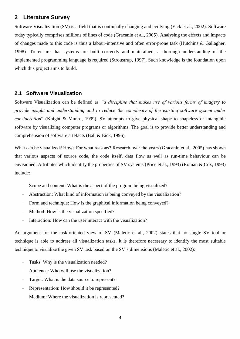
2.1 Software Visualization
Software Visualization can be defined as “a discipline that makes use of various forms of imagery to
provide insight and understanding and to reduce the complexity of the existing software system under
consideration” (Knight & Munro, 1999). SV attempts to give physical shape to shapeless or intangible
software by visualizing computer programs or algorithms. The goal is to provide better understanding and
comprehension of software artefacts (Ball & Eick, 1996).
What can be visualized? How? For what reasons? Research over the years (Gracanin et al., 2005) has shown
that various aspects of source code, the code itself, data flow as well as run-time behaviour can be
envisioned. Attributes which identify the properties of SV systems (Price et al., 1993) (Roman & Cox, 1993)
include:
Scope and content: What is the aspect of the program being visualized?
Abstraction: What kind of information is being conveyed by the visualization?
Form and technique: How is the graphical information being conveyed?
Method: How is the visualization specified?
Interaction: How can the user interact with the visualization?
An argument for the task-oriented view of SV (Maletic et al., 2002) states that no single SV tool or
technique is able to address all visualization tasks. It is therefore necessary to identify the most suitable
technique to visualize the given SV task based on the SV‟s dimensions (Maletic et al., 2002):
Tasks: Why is the visualization needed?
Audience: Who will use the visualization?
Target: What is the data source to represent?
Representation: How should it be represented?
Medium: Where the visualization is represented?

5
2.2 2D and 3D Visualization
Techniques used in two-dimensional visualizations involve graphs or tree-like structures (Van Ham, 2003)
consisting of a large number of nodes and arcs. Complex software systems may consist of thousands of such
nodes and arcs. Examples of systems which provide users with a number of different windows or views to
present varying characteristics or levels of detail include Seesoft (Eick et al., 1992) and SHriMP (Storey et
al., 1997).
There is, however, a negative aspect (Gracanin et al., 2005) inherently associated with two-dimensional
visualizations: cluttering. Although methods for avoiding clutter such as pan/zoom and fisheye (Storey et al.,
1997) have been explored, visualizing software in two-dimensions cannot avoid introducing an information
overload by presenting too much information. Ware et al. (1993) conducted an experiment in which a
subject‟s perception was analysed in both 2D and 3D and concluded that there is empirical evidence that
error rates are less when 3D visualizations are used. GraphVisualizer3D (Ware et al., 1993) was developed
to visualize object-oriented code in 3D taking advantage of the fact that 3D visualizations allow users to
perceive the depth of a presented structure. Stasko (1992) identifies the need for an extra spacial dimension,
stating that “by adding an extra spatial dimension, we supply visualization designers with one or more
possibility for describing some aspect of a program or system”.
Three-dimensions have also been explored for most areas where 2D visualizations are used, such as
visualization to track software errors, isolate problems, monitor progress of development as well as three-
dimensional UML representations (Gracanin et al., 2005).
2.3 Virtual Environments
To provide a better means to explore software structure, the Virtual Environment (VE) should be examined.
VEs open possibilities of immersion and navigation enabling the user to interact with a representation of a
familiar object. The concept of “worlds” in a VE can be associated with “entities” or “components” in a
software system (Gracanin et al., 2005). Source code may be presented and linked in a VE to improve
comprehension. VEs allow users to navigate through links in the world which affords a faster and more
intuitive interface for learning than 2D or 3D structures.
VEs representing object-oriented software systems have been designed and researched. Two of these
systems are ImsoVision (Maletic et al., 2001) and Software World (Knight & Munro, 1999). The former
system represents C++ code within an immersive VE, while the latter does the same for Java code. Both of
these visualization systems can only visualize static properties of the code and cannot be used to represent
the code‟s state in a run-time environment. It is therefore necessary to further investigate metaphors that will
allow us to move beyond representing static code (Asokan, 2003).
6
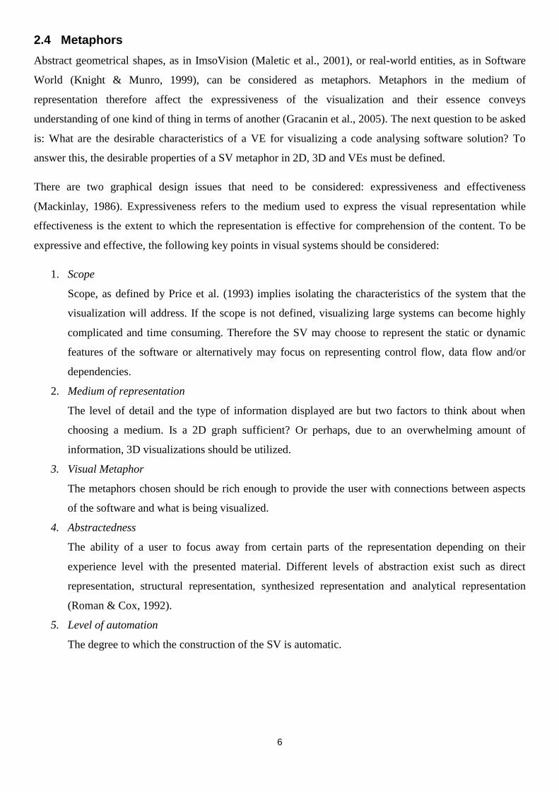
2.4 Metaphors
Abstract geometrical shapes, as in ImsoVision (Maletic et al., 2001), or real-world entities, as in Software
World (Knight & Munro, 1999), can be considered as metaphors. Metaphors in the medium of
representation therefore affect the expressiveness of the visualization and their essence conveys
understanding of one kind of thing in terms of another (Gracanin et al., 2005). The next question to be asked
is: What are the desirable characteristics of a VE for visualizing a code analysing software solution? To
answer this, the desirable properties of a SV metaphor in 2D, 3D and VEs must be defined.
There are two graphical design issues that need to be considered: expressiveness and effectiveness
(Mackinlay, 1986). Expressiveness refers to the medium used to express the visual representation while
effectiveness is the extent to which the representation is effective for comprehension of the content. To be
expressive and effective, the following key points in visual systems should be considered:
1. Scope
Scope, as defined by Price et al. (1993) implies isolating the characteristics of the system that the
visualization will address. If the scope is not defined, visualizing large systems can become highly
complicated and time consuming. Therefore the SV may choose to represent the static or dynamic
features of the software or alternatively may focus on representing control flow, data flow and/or
dependencies.
2. Medium of representation
The level of detail and the type of information displayed are but two factors to think about when
choosing a medium. Is a 2D graph sufficient? Or perhaps, due to an overwhelming amount of
information, 3D visualizations should be utilized.
3. Visual Metaphor
The metaphors chosen should be rich enough to provide the user with connections between aspects
of the software and what is being visualized.
4. Abstractedness
The ability of a user to focus away from certain parts of the representation depending on their
experience level with the presented material. Different levels of abstraction exist such as direct
representation, structural representation, synthesized representation and analytical representation
(Roman & Cox, 1992).
5. Level of automation
The degree to which the construction of the SV is automatic.
7
2.5 Other Applications of SVs
Software Visualizations have been researched and constructed for many different applications.
2.5.1 Software Evolution
There have been attempts to create SV solutions which visualize the evolution of a system. A
forerunner to version history visualization is Seesoft (Eick et al., 1992). Seesoft is a tool that can
visualize up to 50, 000 lines of code of line-oriented software statistics and can then provide
information to the user such as the number of files under version control.
Another work, by Gall et al. (1999), uses colour and 3D visualizations to visualize software release
histories effectively.
2.5.2 Software Security
A possible application of SV is in the area of software security analysis where the results of
dependency and traceability analyses in a software system can be visualized. This can help identify
the potential security vulnerabilities within the software. An SV has been implemented with the
ability to examine the visual fingerprint left by popular network attack tools, to provide a better
understanding of methodologies used by these attackers (Conti & Abdullah, 2004).
2.5.3 Data Mining
SV is used by Burch et al. (2005) for mining software archives. Visualization is extremely useful in
this field as it enables the user visually to sift through vast amounts of data to discover patterns and
analyse information.
2.6 Student Engagement
A study has been undertaken (Grissom et al., 2003) to measure the effect of varying levels of student
engagement with algorithm visualization to learn simple sorting algorithms. Grissom et al. show that
learning increases as the level of student engagement increases. Visualizations therefore have a bigger
impact on learning when students are required to actively engage in the additional activities structured
around the visualization rather than the students passively viewing the visualization.
As a result, this project aims to increase the comprehension of concepts taught in a C/C++ course by
building an SV based on the C/C++ code entered for compilation by the student.

8
2.7 Algorithms and Software Engineering Education
Visualization of software engineering and algorithms can assist instructors to explain as well as help learners
to understand algorithms and programming principles and practices (Hundhausen et al., 2002). For example,
this project aims to show the relevant variables and their values at each line of code following the execution
path of the code. This research is focused on C and C++ due to their popularity (Tiobe Software, 2008).
These languages have been extensively taught in classrooms at school and at a university level and this has
lead to widespread implementation of operating systems, graphics, databases, audio processing to microchip
programming using C/C++.
2.8 Pointers
One of the most powerful aspects of C and C++ is pointers (Deitel & Deitel, 2003). The majority of most
modern-day languages (Java, C#, VB) are able to pass variables by reference and by value. These modern
languages are based in a managed environment which implies that a managed heap is utilized. A managed
heap is an environment whereby the programmer allocates memory for use by the variables and objects, yet
the programmer has no control over this memory. This is a drastically different approach when compared to
the C languages as they provide the ability to manually maintain both the stack and heap without a managed
run-time system. This both complicates the languages as well as providing the programmer with more
refined, more powerful approaches for managing the program resources (Deitel & Deitel, 2003).
Pointers are thus used to provide a more refined pass-by-reference system by allowing the programmer to
manipulate both static and dynamic program data directly (Deitel & Deitel, 2003). The proposed “power” of
pointers however often provides a hurdle to learners (Stroustrup, 1997), hampering their ability to grasp the
concept of effective memory management. The C language‟s ability to manipulate memory is a fundamental
step required in the student‟s understanding of how data structures are implemented, as well as pointers‟
intimate relationship with arrays and strings, which exemplifies the relevance of proper teaching methods.
Vectors, link lists, stacks, queues and other basic data structures used for programming make use of dynamic
data which has the ability to grow and shrink at run-time (Deitel & Deitel, 2003), and at the most basic level
is manipulated by the proper use of pointers.
The C languages support a gradual approach to learning (Stroustrup, 1997) in the sense that the direction
taken depends on what you already know and what you aim to learn. If the aim is to become a better
programmer by learning a new language, then this must be done in a gradual fashion. Acquiring a new skill
takes time and practice, such as when learning to play a musical instrument or learning a natural language.
When learning a new language, according to Stroustrup (1997), the most important thing to focus on are the
concepts and not the language-level details. Stroustrup (1997) states that the purpose of learning a new
9
programming language is to become more efficient at designing, implementing and maintaining systems;
thereby becoming a better programmer.
2.9 Complexity
To reduce development time, ease maintenance and decrease the cost of testing, it is important to reduce the
size and complexity of the software system that is being worked upon (Stroustrup, 1999). This would also
simplify the task of learning C and C++.
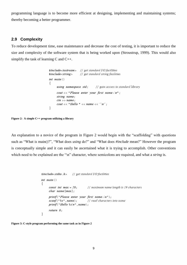
Figure 2: A simple C++ program utilizing a library
An explanation to a novice of the program in Figure 2 would begin with the “scaffolding” with questions
such as “What is main()?”, “What does using do?” and “What does #include mean?” However the program
is conceptually simple and it can easily be ascertained what it is trying to accomplish. Other conventions
which need to be explained are the “\n” character, where semicolons are required, and what a string is.
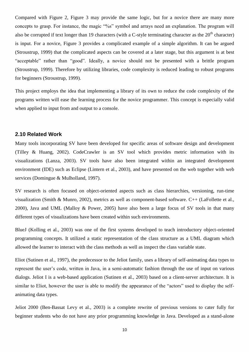
Figure 3: C-style program performing the same task as in Figure 2
10
Compared with Figure 2, Figure 3 may provide the same logic, but for a novice there are many more
concepts to grasp. For instance, the magic “%s” symbol and arrays need an explanation. The program will
also be corrupted if text longer than 19 characters (with a C-style terminating character as the 20th
character)
is input. For a novice, Figure 3 provides a complicated example of a simple algorithm. It can be argued
(Stroustrup, 1999) that the complicated aspects can be covered at a later stage, but this argument is at best
“acceptable” rather than “good”. Ideally, a novice should not be presented with a brittle program
(Stroustrup, 1999). Therefore by utilizing libraries, code complexity is reduced leading to robust programs
for beginners (Stroustrup, 1999).
This project employs the idea that implementing a library of its own to reduce the code complexity of the
programs written will ease the learning process for the novice programmer. This concept is especially valid
when applied to input from and output to a console.
2.10 Related Work
Many tools incorporating SV have been developed for specific areas of software design and development
(Tilley & Huang, 2002). CodeCrawler is an SV tool which provides metric information with its
visualizations (Lanza, 2003). SV tools have also been integrated within an integrated development
environment (IDE) such as Eclipse (Lintern et al., 2003), and have presented on the web together with web
services (Domingue & Mulholland, 1997).
SV research is often focused on object-oriented aspects such as class hierarchies, versioning, run-time
visualization (Smith & Munro, 2002), metrics as well as component-based software. C++ (LaFollette et al.,
2000), Java and UML (Malloy & Power, 2005) have also been a large focus of SV tools in that many
different types of visualizations have been created within such environments.
BlueJ (Kolling et al., 2003) was one of the first systems developed to teach introductory object-oriented
programming concepts. It utilized a static representation of the class structure as a UML diagram which
allowed the learner to interact with the class methods as well as inspect the class variable state.
Eliot (Sutinen et al., 1997), the predecessor to the Jeliot family, uses a library of self-animating data types to
represent the user‟s code, written in Java, in a semi-automatic fashion through the use of input on various
dialogs. Jeliot I is a web-based application (Sutinen et al., 2003) based on a client-server architecture. It is
similar to Eliot, however the user is able to modify the appearance of the “actors” used to display the self-
animating data types.
Jeliot 2000 (Ben-Bassat Levy et al., 2003) is a complete rewrite of previous versions to cater fully for
beginner students who do not have any prior programming knowledge in Java. Developed as a stand-alone

11
application, the graphical user interface (GUI) of Jeliot 2000 takes the form of a theatre in which the user
types in the code and presses the “Play” button for the animation to occur. Animations are used to visualize
how the expressions are being evaluated at run-time, and all aspects of the visualizations are shown on the
screen at the same time in two-dimensions. An empirical evaluation of Jeliot 2000 was undertaken (Ben-
Bassat Levy et al., 2003) between two classrooms, one without any aid of a VS and the other utilizing Jeliot
2000. The results showed that the improvement rate of the treatment class had increased, however the major
finding was that the treatment class had formed a vocabulary of verbal and visual terms of the programming
concepts taught, facilitating discussions of these concepts.
Jeliot 3 (Myller, 2004) is closely based on the work of Jeliot 2000, retaining the GUI of the previous
version; however modularity was the main focus and therefore the components within the system were
designed to be loosely coupled. The parser and interpreter of Jeliot 3 were redesigned, along with the self-
animating library of data types to fit their aim of modularity.
12
3 The Translator and Grammar
A new and simple language has been designed for this project called CMinor. The user‟s source code,
written in CMinor, must be syntactically and semantically correct to allow a visual to be produced. This is
accomplished through the use of a translator. But first, the basic concepts of translators must be introduced.
3.1 Background of Translators
3.1.1 Translation Phases
A translator is a complicated program which takes various steps to complete (Terry, 2005). In order to
analyse these steps, two main phases can be identified: the analytical phase and the synthetic phase (Terry,
2005). The analytical phase is where the source code of the program is read and analysed to determine
whether the syntactic and semantic constraints of the language are met. The synthetic phase proceeds by
generating the corresponding object code for the target machine. These two phases comprise the front end
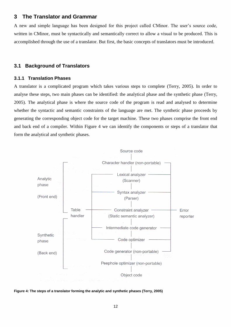
and back end of a compiler. Within Figure 4 we can identify the components or steps of a translator that
form the analytical and synthetic phases.
Figure 4: The steps of a translator forming the analytic and synthetic phases (Terry, 2005)
13
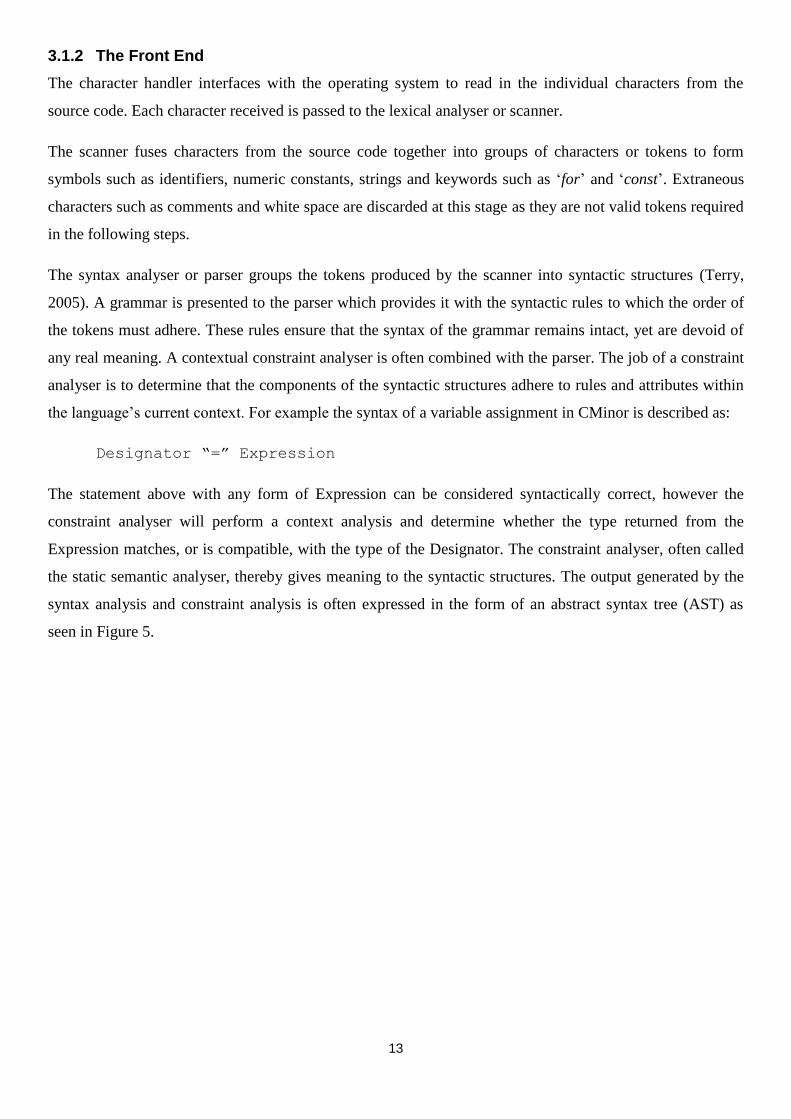
3.1.2 The Front End
The character handler interfaces with the operating system to read in the individual characters from the
source code. Each character received is passed to the lexical analyser or scanner.
The scanner fuses characters from the source code together into groups of characters or tokens to form
symbols such as identifiers, numeric constants, strings and keywords such as „for‟ and „const‟. Extraneous
characters such as comments and white space are discarded at this stage as they are not valid tokens required
in the following steps.
The syntax analyser or parser groups the tokens produced by the scanner into syntactic structures (Terry,
2005). A grammar is presented to the parser which provides it with the syntactic rules to which the order of
the tokens must adhere. These rules ensure that the syntax of the grammar remains intact, yet are devoid of
any real meaning. A contextual constraint analyser is often combined with the parser. The job of a constraint
analyser is to determine that the components of the syntactic structures adhere to rules and attributes within
the language‟s current context. For example the syntax of a variable assignment in CMinor is described as:
Designator “=” Expression
The statement above with any form of Expression can be considered syntactically correct, however the
constraint analyser will perform a context analysis and determine whether the type returned from the
Expression matches, or is compatible, with the type of the Designator. The constraint analyser, often called
the static semantic analyser, thereby gives meaning to the syntactic structures. The output generated by the
syntax analysis and constraint analysis is often expressed in the form of an abstract syntax tree (AST) as
seen in Figure 5.

14
Figure 5: An abstract symbol tree formed by the expression: x = p + q * 10
3.1.3 The Back End
An intermediate code generator may be integrated in earlier steps as part of the front end of a translator or
may be omitted altogether in simple translators. The form of code generated at this step is ASSEMBLER, a
code skeleton, a macro or another high-level/intermediate code for processing by an external interpreter.
More information regarding the intermediate code generated in this project can be found in Section 4.1.
Optionally, a code optimizer may be present in an attempt to improve the intermediate code by making a
trade-off between speed and space. Terry (2005) gives the following example of how the code optimizer
changes the intermediate code (Figure 6).
Figure 6: Low level operational codes can be optimized by the code optimizer to produce more efficient code
The code generator is the heart of the back end of a translator as it takes the output from the previous steps
and produces object code. Some of the tasks of the code generator (Terry, 2005) are to decide on the
memory locations of data, generate code to access these locations, select registers to be used.
Assignment
Designator Expression (assign)
p
+
*
q 10
L0 if 1 < p goto L1
goto L3
L1 if p < 9 goto L2
goto L3
L2 p = p + q
goto L0
L3 continue
L0 if 1 >= p goto L1
if P >= 0 goto L1
p = p + q
goto L0
L1 continue
while( 1 < p && p > 9 ) p = p + q;
15
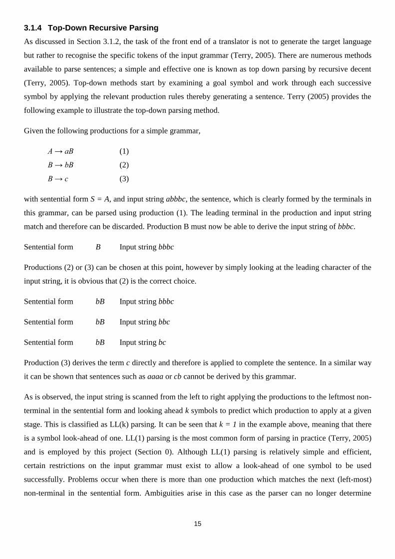
3.1.4 Top-Down Recursive Parsing
As discussed in Section 3.1.2, the task of the front end of a translator is not to generate the target language
but rather to recognise the specific tokens of the input grammar (Terry, 2005). There are numerous methods
available to parse sentences; a simple and effective one is known as top down parsing by recursive decent
(Terry, 2005). Top-down methods start by examining a goal symbol and work through each successive
symbol by applying the relevant production rules thereby generating a sentence. Terry (2005) provides the
following example to illustrate the top-down parsing method.
Given the following productions for a simple grammar,
A → aB (1)
B → bB (2)
B → c (3)
with sentential form S = A, and input string abbbc, the sentence, which is clearly formed by the terminals in
this grammar, can be parsed using production (1). The leading terminal in the production and input string
match and therefore can be discarded. Production B must now be able to derive the input string of bbbc.
Sentential form B Input string bbbc
Productions (2) or (3) can be chosen at this point, however by simply looking at the leading character of the
input string, it is obvious that (2) is the correct choice.
Sentential form bB Input string bbbc
Sentential form bB Input string bbc
Sentential form bB Input string bc
Production (3) derives the term c directly and therefore is applied to complete the sentence. In a similar way
it can be shown that sentences such as aaaa or cb cannot be derived by this grammar.
As is observed, the input string is scanned from the left to right applying the productions to the leftmost non-
terminal in the sentential form and looking ahead k symbols to predict which production to apply at a given
stage. This is classified as LL(k) parsing. It can be seen that k = 1 in the example above, meaning that there
is a symbol look-ahead of one. LL(1) parsing is the most common form of parsing in practice (Terry, 2005)
and is employed by this project (Section 0). Although LL(1) parsing is relatively simple and efficient,
certain restrictions on the input grammar must exist to allow a look-ahead of one symbol to be used
successfully. Problems occur when there is more than one production which matches the next (left-most)
non-terminal in the sentential form. Ambiguities arise in this case as the parser can no longer determine

16
which production rule to follow. Simple languages such as Pascal, Modula-2 and simple C-like languages
can avoid such ambiguities, but C, and especially C++, have productions with multiple matching left-most
non-terminals in their grammar productions. Such LL(1) conflicts can be resolved by a multi-symbol look
ahead (LL(k)) or by implementing semantic checks (Institut für Systemsoftware, 2008).
3.1.5 Available Parsing Tools
A parser is one of the major aspects of this project and as such required much deliberation. C and C++
compilers have been available for many years and each contains a parser. The most obvious place to look for
a parsing tool for C++ is gcc (GNU Project, 2008). As a freely distributed and fully functional C++
compiler, it must be able to parse C++ successfully. Upon closer inspection, it was found that the various
stages of parsing (Section 3.1.1) are merged together and that the poor documentation provides little insight
to the inner workings of gcc. Gcc supports all aspects of the C++ language and as such can be considered a
complete C++ translator that also provides a symbol table combined with good performance. It was decided
that although gcc provides a comprehensive parsing solution it would be a non-trivial task to integrate its
output within the confines of the scope of this project to produce visual output.
Source Navigator (sourcenav NG development group, 2008) is cited as a “source code analysis tool”. It
operates by parsing the source code and enters the metadata gathered into database tables. From this point it
allows the user to edit the source code, display relationships between classes, functions and members and
display call trees. The actual parser found in Source Navigator is highly complex and is of very little
educational use.
ANTLR (Parr) is a parser generator operating on a predicted LL(k) grammar. This means that it uses a look
ahead of k symbols which is used to predict which grammar production will be followed. Additionally
ANTLR allows the grammar to specify syntactic and/or semantic predicates thereby giving unique attributes
to the productions. An example of this is if the parser looks up a certain identifier in the symbol table and
then determines the next production to use is based on the type retrieved.
Upon further investigation of the ANTLR parser, a C/C++ grammar developed by Sun Microsystems (Sun
Microsystems, 2008) was found that provides a fully attributed grammar used by the Netbeans IDE
environment (Sun Microsystems, 2008). Using ANTLR and the grammar developed by Sun Microsystems
(Sun Microsystems, 2008) appeared to be the best approach to use in designing a translator for this project.
Due to Sun‟s grammar being very comprehensive and encompassing the entire C and C++ languages,
problems arose when making even very simple modifications. For example, in order to remove the
grammar‟s ability to parse classes, as they fall out of the scope of this project, it was found that many of the
productions and attributes were reliant upon information contained in the class productions. Modifying such
17
a large grammar, which is tightly coupled, to allow only a very small subset of a language to be parsed
(Section 3.2) makes little sense. The best possible route would be to base a new grammar (or a modified
similar grammar) on the C++ BNF grammar provided by Stroustrup (1997). ANTLR is a very
comprehensive parsing utility; however such a powerful tool is beyond the requirements of this project.
Originally developed by Hanspeter Mössenböck, Coco/R (Institut für Systemsoftware, 2008) is a tool very
similar to ANTLR in that it takes an attributed grammar of a source language and generates a scanner and
parser for a target language. The attributed grammar is written using the EBNF syntax with attributes and
semantic actions that conform to LL(1) restrictions. The task rests on the user to supply modules for symbol
table handling, optimization and code generation to build a running compiler.
Coco/R was chosen as the tool to generate the front end for this project due to its ease of use, simple
integration of semantic actions and modularity regarding the symbol table. A benefit of using Coco/R is that
it can be used to construct other syntax-based applications that are less like a “compiler” and more like a
parser for a programming language.
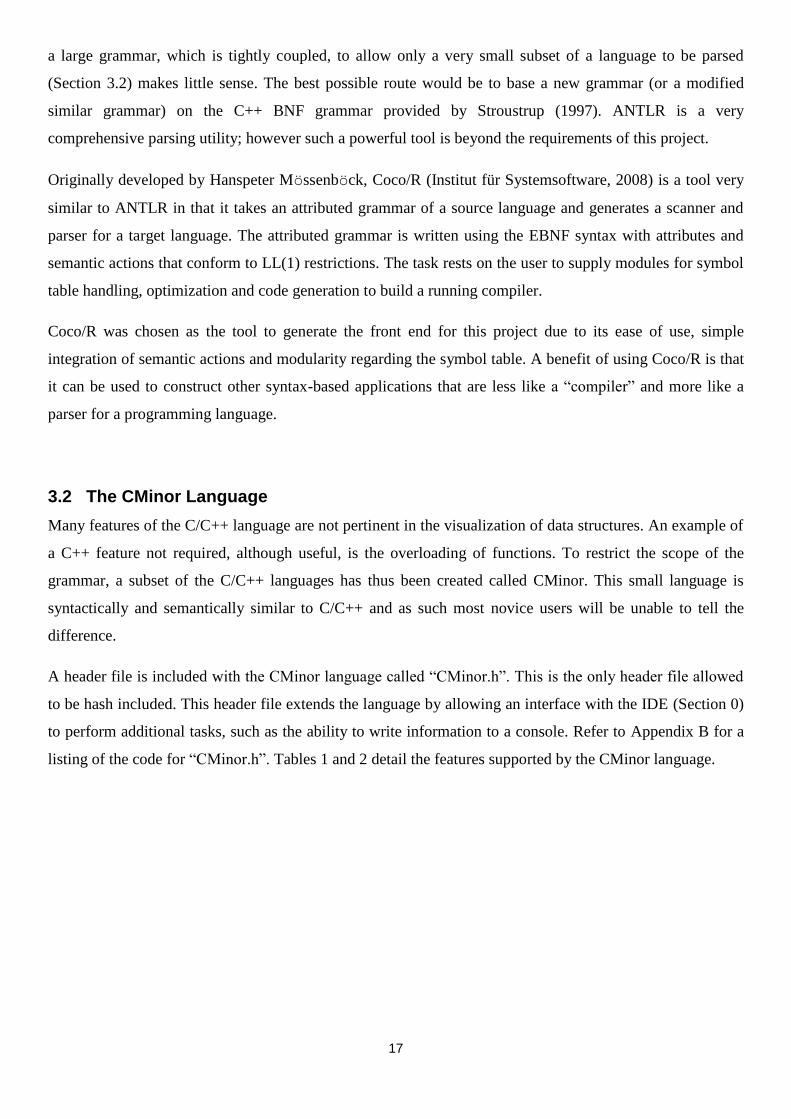
3.2 The CMinor Language
Many features of the C/C++ language are not pertinent in the visualization of data structures. An example of
a C++ feature not required, although useful, is the overloading of functions. To restrict the scope of the
grammar, a subset of the C/C++ languages has thus been created called CMinor. This small language is
syntactically and semantically similar to C/C++ and as such most novice users will be unable to tell the
difference.
A header file is included with the CMinor language called “CMinor.h”. This is the only header file allowed
to be hash included. This header file extends the language by allowing an interface with the IDE (Section 0)
to perform additional tasks, such as the ability to write information to a console. Refer to Appendix B for a
listing of the code for “CMinor.h”. Tables 1 and 2 detail the features supported by the CMinor language.
18
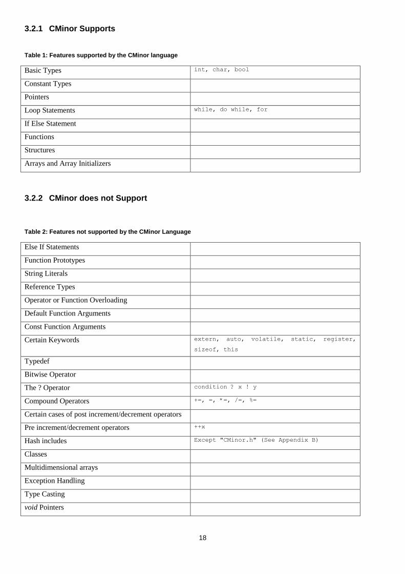
3.2.1 CMinor Supports
Table 1: Features supported by the CMinor language
Basic Types int, char, bool
Constant Types
Pointers
Loop Statements while, do while, for
If Else Statement
Functions
Structures
Arrays and Array Initializers
3.2.2 CMinor does not Support
Table 2: Features not supported by the CMinor Language
Else If Statements
Function Prototypes
String Literals
Reference Types
Operator or Function Overloading
Default Function Arguments
Const Function Arguments
Certain Keywords extern, auto, volatile, static, register,
sizeof, this
Typedef
Bitwise Operator
The ? Operator condition ? x ! y
Compound Operators +=, =, *=, /=, %=
Certain cases of post increment/decrement operators
Pre increment/decrement operators ++x
Hash includes Except "CMinor.h" (See Appendix B)
Classes
Multidimensional arrays
Exception Handling
Type Casting
void Pointers

19
3.3 Developing the Grammar
The CMinor grammar is based on two separate works. For a full listing of the CMinor grammar, see
Appendix C.
Terry (2005) provides a complete working parser, code generator and symbol table along with semantic
actions for a language dubbed C#Minor. This language is a minimal object-oriented programming language
which has evolved from C# and Java. It incorporates integer, character and Boolean types as fields, methods
or constants, one-dimensional arrays and the manipulation of objects. Upon first glance this looks to be very
similar to what this project is trying to accomplish with CMinor. While and Do While loops, expression
evaluation and type checking have already been implemented in such a way that is easily understandable,
but more importantly, easily modified.
The C#Minor grammar has been designed, upon compilation, to generate a byte-code language to be
interpreted by either the Java Virtual Machine (JVM) or Common Language Runtime (CLR) of Sun
Microsystems and Microsoft‟s .NET Framework respectively. This aspect of a translator, as discussed in
Section 3.1, is handled by the back end of the translator. The first step in making use of the C#Minor
grammar by Terry (2005) is effectively to remove all aspects of the grammar which generate JVM byte-code
or CLR instructions. This project does not make use of the JVM or CLR to run the user‟s program as that
would require receiving a call back on each instruction interpreted by the run-time engine to visualize the
memory mapping of variables. Both the JVM and CLR are managed systems and as such do not form a
proper correlation with the C/C++ environment. For this reason a custom-built interpreter has been
constructed (Section 4) that executes the instructions generated by the CMinor translator in such as way as
to facilitate the visualization aspect of this project. Coco/R generates C# classes to perform the scanning,
parsing and code generation aspects of a translator. This project makes use of the C# language and its run-
time engine to execute, however the task is upon the CMinor interpreter to simulate an unmanaged
environment within a managed one.
The C#Minor grammar required drastic modifications for it to fit the CMinor mould. Classes, forming a
major portion of C#Minor, are beyond the scope of this project and as such not supported. However the class
handling aspect of the C#Minor language formed an important basis for the implementation of a structure‟s
syntax. After modifying the class production by effectively renaming class to struct, removing the ability to
define methods inside a class, removing the member modifiers (public, private and protected) and ensuring a
semi-colon is present at the end of the structure definition, a perfectly valid structure production has been
created. Due to a class and structure being a distinct “entity” (or object) many semantic actions already in
place hold and required little alteration.

20
However before semantic actions are put in place to provide the grammar with “meaning” (Section 3.1.2),
the actual syntax of CMinor has to be defined. Stroustrup‟s (1997) BNF grammar for C++ formed the
second work upon which CMinor was based. Utilizing Stroustrup‟s grammar, many missing features of the
C#Minor language could be successfully implemented. An example of such a feature is a for loop (Figure
7). Due to the restrictions placed upon the grammar as a result of LL(1) parsing, Stroustrup‟s grammar had
to be altered in certain cases to maintain compliance with the respective LL(1) rules.
Figure 7: An LL(1) compatible set of productions to parse a for loop successfully
A major alteration to the C#Minor grammar was the typing infrastructure. Basic type pointers and structure
pointers had to be added to the grammar (Figure 8) which posed a great challenge. Many new semantic
checks had to be put in place to ensure that the integrity of the pointer was valid. Pointer arithmetic and
pointer assignments had to mimic the exact functionality of a real C/C++ application. The ampersand (&)
and dereference (*) operators also had to be incorporated into the language along with their semantic
actions. A pointer is therefore not just another “type” which had to be integrated into CMinor, but an entirely
new category of type with its own regulations that differ from those of a regular type (i.e., an integer).
Figure 8: Grammar productions allowing a pointer type to be declared on basic variable types
ForStatement
= "for" WEAK "(" ForInitStatement
[ Condition ] ";"
[ ForExpression {"," ForExpression } ]
WEAK ")" SYNC Statement
.
ForInitStatement
= AssignCallObjDecl | VarDeclarations | ";"
.
ForExpression
= ["*"] Designator
(
( AssignOp Expression | "++" | "--" )
)
.
BasicType
= ((( "int" | "char" ) [PointerType] )
| "bool" )
.
PointerType
= "*"
.

21
CMinor must also support pointers to structures as these form an integral part in the construction of data
structures. As such the dot (.) and arrow (->) operators were implemented. Ensuring that semantic rules were
in place to prohibit inappropriate use of these operators took much trial and error as well as comparisons
with how a real C/C++ compiler treats the operators in various test cases. An example of an inappropriate
use of the arrow operator would be to point to a variable which is being dereferenced by the dereference
operator thereby causing an illegal indirection error.
Arrays, and pointers to arrays, also proved troublesome and required much deviation from the C#Minor
grammar. Syntactically the main difference in C#Minor is in the array declaration compared to C/C++. In
C#Minor however, an array is seen as an entirely different type therefore prohibiting assigning a non-array
type to an array. This had to be overcome in CMinor as a pointer of a certain type must be able to point to an
array of a similar type, effectively making the pointer hold the memory address of the first element in the
array. Passing an array as an argument to a function can be done in two ways: using array notation or by
using pointer notation. Both syntax formats had to be implemented along with corresponding semantics to
ensure that the array and its elements are accessed correctly.
Other changes had to be made with respect to how certain expressions are evaluated. For example, the
majority of basic types in C/C++ can be equated to an integer (including the Boolean type) which is not
possible in C#Minor. A NULL type was implemented to which every type in C/C++ can be assigned thereby
effectively giving the variable a value of zero.
The CMinor.h header file (Appendix B) has been embedded within the grammar itself and not as a separate
header file. Through the use of semantics within the grammar, the behaviour of hash including this header
file can be simulated. If the source code does not contain the valid hash define statement, a Boolean variable
within the grammar will be set to false throughout the parsing instance. Therefore when the user tries to call
a function requiring the CMinor.h header file, a semantic check is performed on the Boolean and if it is not
set an “undefined function” error will be shown to the user. This prevents the user from utilizing functions
without first declaring them by the inclusion of the appropriate header file. This is a clear example of how
semantics can be used to give additional meaning to a grammar.

22
4 Interpreter
The CMinor source code has passed through the translator and as such meets the syntax and semantic
constraints enforced by the grammar. The resultant output of the parser is a high-level, structured
intermediate language which is passed onto the interpreter. An unmanaged environment must then be
initialized and the individual tokens processed in order to execute the user‟s code.
4.1 Intermediate language
The intermediate language is passed on to the interpreter after a successful run of the parser on a source file.
As such, the intermediate language needs to encompass all the functionality of the CMinor language and
present the instructions in such a way for the interpreter to be able to perform the required actions.
C#Minor contains the back end of a translator which generates code for the Java Virtual Machine or the
.NET Runtime. This low-level language embodies the actions that the user is trying to perform from their
source code. Each line of source code is translated into many low-level commands which utilize exact
memory addresses and perform operations based on these. Each instruction is interpreted by the virtual
machine to provide a functioning application. These instructions could be used and a memory map could be
visualized from them, however the Visualizer (Section 5) steps through each line of the source file at a time,
performing the actions specified on that specific line. The low-level byte code has no recollection of, or any
similarity to, the source code thus making this task impossible.
The actual tokens read from the source file in CMinor cannot be sent “as is” to the interpreter. Many
variations exist within the syntax of CMinor, making the task of the interpreter very difficult in trying to
interpret all possible syntax ambiguities successfully. An example of such ambiguities can be seen in
Figure 9.
Figure 9: Missing braces around the inner for loop body is a clear example of syntax ambiguities and why an intermediate language is required
There is no clear end to the inner for loop. By sending these tokens to the interpreter, it must be able to
handle all cases of syntax differences which is a non-trivial procedure. Therefore an intermediate language
for(int i = 0; i < 10; i++)
{
for(int j = 0; j < 10; j++)
arr[i][j] = i+j;
}
23
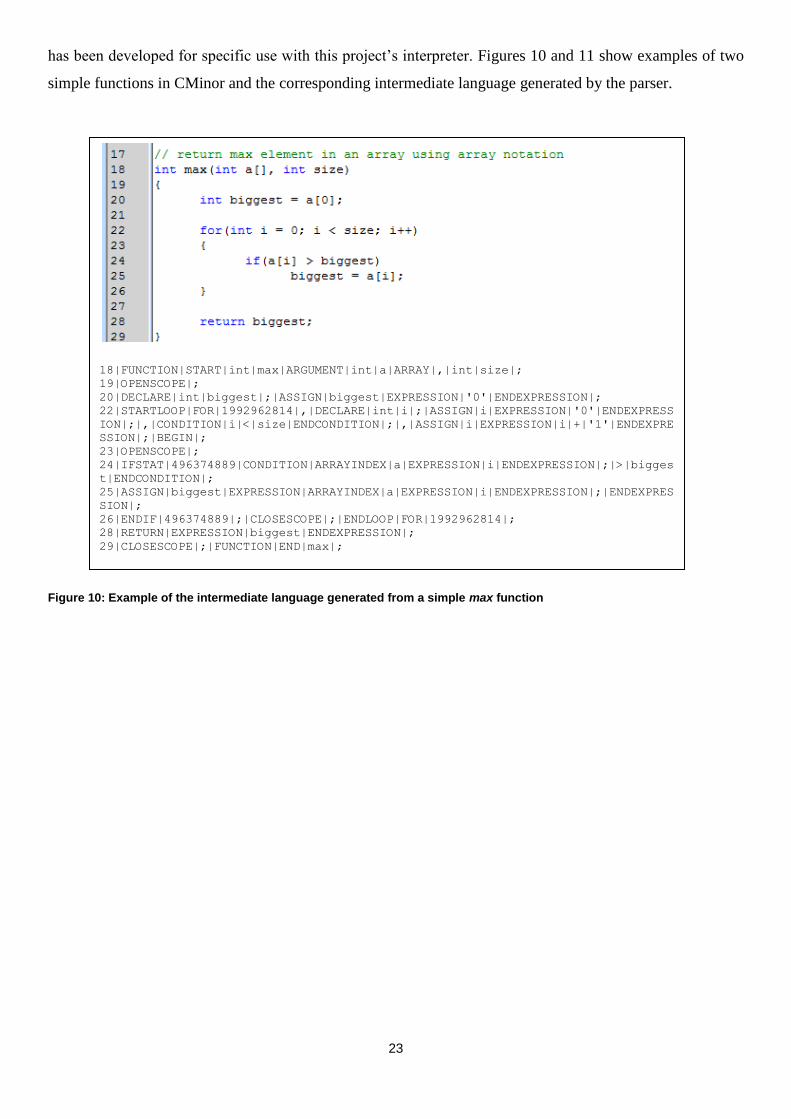
has been developed for specific use with this project‟s interpreter. Figures 10 and 11 show examples of two
simple functions in CMinor and the corresponding intermediate language generated by the parser.
Figure 10: Example of the intermediate language generated from a simple max function
18|FUNCTION|START|int|max|ARGUMENT|int|a|ARRAY|,|int|size|;
19|OPENSCOPE|;
20|DECLARE|int|biggest|;|ASSIGN|biggest|EXPRESSION|'0'|ENDEXPRESSION|;
22|STARTLOOP|FOR|1992962814|,|DECLARE|int|i|;|ASSIGN|i|EXPRESSION|'0'|ENDEXPRESS
ION|;|,|CONDITION|i|<|size|ENDCONDITION|;|,|ASSIGN|i|EXPRESSION|i|+|'1'|ENDEXPRE
SSION|;|BEGIN|;
23|OPENSCOPE|;
24|IFSTAT|496374889|CONDITION|ARRAYINDEX|a|EXPRESSION|i|ENDEXPRESSION|;|>|bigges
t|ENDCONDITION|;
25|ASSIGN|biggest|EXPRESSION|ARRAYINDEX|a|EXPRESSION|i|ENDEXPRESSION|;|ENDEXPRES
SION|;
26|ENDIF|496374889|;|CLOSESCOPE|;|ENDLOOP|FOR|1992962814|;
28|RETURN|EXPRESSION|biggest|ENDEXPRESSION|;
29|CLOSESCOPE|;|FUNCTION|END|max|;

24
Figure 11: Example of the intermediate language generated for a structure definition and append function for a linked list
4|STRUCT|START|node|;
5|DECLARE|int|data|;
6|DECLARE|node|next|DEREF|;
7|STRUCT|END|node|;
10|DECLARE|GLOBAL|node|p|DEREF|;
13|FUNCTION|START|void|append|ARGUMENT|int|num|;
14|OPENSCOPE|;
15|DECLARE|node*|q|;|DECLARE|node*|t|;
17|IFSTAT|1338149892|CONDITION|p|==|'NULL'|ENDCONDITION|;
18|OPENSCOPE|;
19|ASSIGN|p|EXPRESSION|HEAPALLOC|node|ENDEXPRESSION|;
20|ASSIGN|STRUCT|p|->|data|EXPRESSION|num|ENDEXPRESSION|;
21|ASSIGN|STRUCT|p|->|next|EXPRESSION|'NULL'|ENDEXPRESSION|;
22|CLOSESCOPE|;
23|ENDIF|1338149892|;
24|ELSESTAT|1338149892|;|OPENSCOPE|;
25|ASSIGN|q|EXPRESSION|p|ENDEXPRESSION|;
26|STARTLOOP|WHILE|1605528512|;|CONDITION|STRUCT|q|->|next|!=|'NULL'|ENDCONDITIO
N|;
27|ASSIGN|q|EXPRESSION|STRUCT|q|->|next|ENDEXPRESSION|;|ENDLOOP|WHILE|1605528512
|;
29|ASSIGN|t|EXPRESSION|HEAPALLOC|node|ENDEXPRESSION|;
30|ASSIGN|STRUCT|t|->|data|EXPRESSION|num|ENDEXPRESSION|;
31|ASSIGN|STRUCT|t|->|next|EXPRESSION|'NULL'|ENDEXPRESSION|;
32|ASSIGN|STRUCT|q|->|next|EXPRESSION|t|ENDEXPRESSION|;
33|CLOSESCOPE|;
34|ENDELSE|1338149892|;|CLOSESCOPE|;|FUNCTION|END|append|;
25
As Figures 10 and 11 illustrate, the intermediate language translates the CMinor language into a more
structured form, for example the beginning and ending of a loop is clearly discernable. Each token is
separated by the pipe (|) symbol and each statement is terminated by a semi-colon. Most importantly,
however, is the correlation between the line numbers and tokens. This recording of line numbers allows the
interpreter to execute the exact instructions on a line-by-line basis.
4.2 Interpreter Data Structures
Before the interpreter is able to start executing instructions, a viable environment must exist in which it can
operate. As such, certain data structures must be defined for the interpreter to maintain the current program‟s
state, process variables, call and return to and from functions as well as output data to a console.
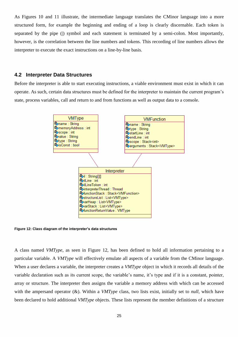
Figure 12: Class diagram of the interpreter’s data structures
A class named VMType, as seen in Figure 12, has been defined to hold all information pertaining to a
particular variable. A VMType will effectively emulate all aspects of a variable from the CMinor language.
When a user declares a variable, the interpreter creates a VMType object in which it records all details of the
variable declaration such as its current scope, the variable‟s name, it‟s type and if it is a constant, pointer,
array or structure. The interpreter then assigns the variable a memory address with which can be accessed
with the ampersand operator (&). Within a VMType class, two lists exist, initially set to null, which have
been declared to hold additional VMType objects. These lists represent the member definitions of a structure
26
and the elements in an array respectively. Upon declaration of an array, the interpreter will create a VMType
object, set the name to the name of the array and populate the array list with new VMType objects each
representing each individual element in that array. Therefore when accessing an element of the array, the
VMType with the array name is first located, and then the list is referenced at the required position. A very
similar process occurs when working with structures, except the structure list is populated instead of the
array list.
By utilizing the VMType class, the interpreter has access to all the details of any variable and as such can
perform operations on their values as per the user‟s instructions. This system thereby removes the need for a
low level opcode-based intermediate language as the interpreter makes use of C# constructs to execute
operations.
Another data structure required by the interpreter is one that contains information about the functions
defined within the source code. If a function call occurs, the current position in a function must be stored
and the program counter moved to the beginning of the new function. Likewise when a function has finished
executing, the program counter must be returned to the calling function and if there is a value to be returned
it must also be stored. Therefore a class called VMFunction (Figure 12) has been defined which encapsulates
all aspects of a function, such as its name, type, scope, beginning line and end line. The arguments and
return value of the function are stored as a VMType. VMFunction objects are created and stored by the
interpreter during its first pass of the intermediate language (Section 4.3.1).
Four lists are defined for use by the interpreter. Two, containing VMType variables, are representative of the
stack and heap memory spaces. The third holds the skeleton definition of a structure as created by the first
pass of the interpreter. Upon declaration of a structure, this structure list is searched for a matching name of
the respective structure which is then copied and added to the stack or heap lists for later use. The fourth list
contains the definitions of VMFunction objects.
4.3 Operation of the Interpreter
4.3.1 First Pass: Environment Initialization
The interpreter passes over the intermediate code in order to setup the program‟s environment by initializing
the various data structures (Section 4.2). Firstly it tokenizes the intermediate code (Section 4.1) and stores
the tokens in a form that is easily accessible. The pipe symbol between each token in the intermediate
language makes the tokenizing process trivial. It then maps the line numbers, as seen in Figure 10 and
Figure 11, to a two-dimensional array with the first dimension representing the line number and the second
holding the individual tokens for that line.

27
When the interpreter starts executing the intermediate code, beginning in the main function, certain
information must be present for successful execution of the program. The interpreter must therefore run
through all tokens from the beginning to end before “executing” the program, effectively performing
compile-time code generation by initializing the data structures.
Certain tokens are searched for during the first pass such as global variable, function and structure
declarations. Global variables are created, assigned a global scope and placed on the interpreter‟s stack list.
Initializations of global variables also occur at this stage. The starting position, arguments received, ending
position and type of a function are recorded in VMFunction objects as these tokens are processed.
Structure skeletons are also added to the structure list during this phase. These VMType objects contain the
name and elements of the structure being defined. This provides a blueprint of the structure which is later
copied and placed in the stack or heap lists by the interpreter upon declaration of the type.
Certain run-time errors, which are unable to be checked by the parser, are also caught by the interpreter
during the first pass. An example of an error that is caught at this stage is a global or structure member array
with a negative array index.
The final step of the first pass is to set the program counter to the first token of the main function. A signal is
sent to the GUI to prepare for the interpretation process to proceed if no errors have been detected and once
all structures have been initialized.
4.3.2 Second Pass: Interpreting Tokens
The interpreter is designed to read tokens from the intermediate language in a particular order. Many
different techniques are used in the interpreting of these tokens such as recursion (loops, function calls) as
well as a look-ahead. By peeking at a token that is still to come, different paths may be taken which cannot
be determined from the value of the current token. This technique is employed to determine, for example, if
there is an else statement following an if statement, if during an assignment (Figure 13) an array index is
being referenced, if a variable is being declared as a constant, etc.
An example, taken from Figure 10, can be used to illustrate the internal workings of the interpreter.

28
ASSIGN|biggest|EXPRESSION|ARRAYINDEX|a|EXPRESSION|i|ENDEXPRESSION|;|ENDEXPRESSION|;
Start
Token Variable Evaluate Array Array Name Array Index
Figure 13: Tokens and expressions as evaluated by the interpreter
When the interpreter encounters the token ASSIGN it knows that the next token it will receive will be the
name of a variable. The stack list is then searched for a variable with the name of the next token as it must
have a reference to the specific VMType object to modify its value. In the case that no variable matches the
name of the token, the interpreter will throw an exception and the interpreter will halt, however errors such
as these are most often ruled out during the parsing phase. The interpreter now knows of the variable and
must set its value which it does by calling upon the expression evaluation handler. The expression handler
builds an expression tree according to the precedence rules, as defined by Stroustrup (1997), and returns a
value after the tree has been evaluated. The expression handler reads the ARRAYINDEX token which is an
instruction to return a value within an array. The following token is the name of the array which is searched
for in the stack. The array index is in itself an expression and the expression handler must call itself to
generate a different expression tree to return a value for the index. Once the index is returned, the interpreter
retrieves the value of the VMType object at that position in the array that ends the expression evaluation. As
the semantic actions of the parser in previous steps have validated this operation, the value of the variable
can then be set to the value returned by the expression evaluation.
4.3.3 Scope
Scoping, whether implied by the language or explicitly stated by the programmer, need only occur within
the stack. Each function, once called, has an associated VMFunction object defined and placed on a stack
within the object. The VMFunction class (Figure 12) defines a stack of integers as a container to hold the
scopes of the currently executing function within the interpreter. As a scope opens, a unique integer is
pushed onto this stack. All variables declared from that moment on are given this value as their stack
reference. Upon the closure of a scope, all variables with a scope reference matching the value popped from
the scope stack are removed. Utilizing this system provides a full scoping system that effectively manages

29
the variables within the stack, as well as providing all relevant information for the Visualizer (Section 5) to
display variables in different scopes.
4.3.4 Errors
Run-time errors can occur within a C/C++ program, and as such the CMinor interpreter should mimic that
behaviour. These are errors that cannot be foreseen during parsing as the variables are not active in working
memory at that point in time and therefore do not have values associated with them. When a run-time
exception is thrown, program execution halts and the GUI is signalled to show that an error has occurred.
The following are the most common run-time exceptions that are thrown during normal C/C++ program
execution and are supported by the CMinor interpreter:
Divide by Zero
Null Pointer Exception
A further restriction imposed by the CMinor interpreter is that a variable cannot be used until it has been
initialized. If a user tries to perform an action on a variable without first initializing it, a run-time error will
be thrown and program execution will halt. If a user makes use of an un-initialized variable in a C/C++
environment, the value of the variable will be whatever is currently in memory at that point in time, which
normally produces an unexpected result. Therefore, as a teaching tool, it was decided to prevent this from
happening and instil the user with a sense of good programming practice.
The CMinor interpreter will also present the user with run-time warnings. Such warnings will not halt the
execution of the program, yet are present to provide additional information not normally received in a
C/C++ environment. In such cases where warnings are given, the programmer is more often than not
performing an operation that will return an unexpected result yet is not a critical error. An example of such a
case is an “Array Out of Bounds” warning. Although valid in a C/C++ context, working outside the bounds
of an array is not considered good programming practice and therefore a warning is given to the user to
indicate this.
4.3.5 Memory Leaks
An important aspect of a C/C++ implementation is memory management (Section 2.8). The CMinor
language does not have a managed heap, exactly as in a C/C++ environment, which implies that if users
allocate memory it is their responsibility to de-allocate it. As a teaching tool the CMinor interpreter provides
a mechanism, once the “HALT” token is processed at the end of a program, which displays all memory

30
leaks (Figure 14). This verbosity is intended to focus the users attention on the fact that managed memory
has not been managed correctly and alter the source code to rectify the problem.
Figure 14: Memory dump produced by the interpreter

31
5 Visualization
The aim of the Visualizer is to generate a visual based on the currently executing code in the interpreter. The
drawing area is divided into a stack and heap, which the Visualizer utilizes to draw the variables as
contiguous memory blocks. The GUI developed and visuals produced have been designed to assist the user
in their learning and understanding of the C/C++ environment.
5.1 Similar Work
In a study conducted by Lattu et al. (2003) it was found that the vizualization of programs, and their various
components, was an important part of the communication process in assignments as well as in the teaching
environment. Many variations of explanation strategies exist and as such there is a demand for a general
purpose visualization tool, especially in the field of C and C++ due to their popularity in academic and
professional environments (Tiobe Software, 2008).
Both Ford (1993) and Lattu et al. (2003) specify a range of criteria which should be met when visualizing
programs:
Ability to browse through the source code throughout all states of the Visualizer .
Syntax highlighting as a feature since this greatly assists novices when learning a language as well as
reduces the number of mistakes (Myller, 2004).
Informative error messages that help direct the user‟s attention to the exact position of the error.
Simple user interface to reduce the learning curve in a new programming environment and encourage
the users to test code.
Adjustable speed of animations to match the pace of the user.
Jeliot 3 (Myller, 2004), as discussed inSection 2.10, provides a simple user interface matching all of the
above criteria. Jeliot 3 makes use of a theatre metaphor in which users type in their code, press a Play button
and the actors produce the animations within a 2D virtual environment. Jeliot 3 divides the screen space into
certain panels (Figure 15) through which each panel is responsible for the control, visualization and output
of the program and can be moved around to suit the needs of the user. As such, there are many similarities
between the aims and objectives of Jeliot 3 and the CMinor Visualizer.
Jeliot 3 supports a vast array of Java features with an object-orientation focus. Due to the fact that Java is a
managed language, all variable and class declarations occur on the managed heap which is not the case in
C/C++. Jeliot 3 has one main visualization area for this managed heap which is further divided into a
Method Area, Expression Evaluation Area and Constant Area in which varying animations occur (Figure
16).

32
Figure 15: Screenshot of Jeliot 3 (Myller, 2004)
Figure 16: Structural layout of Jeliot 3 (Myller, 2004)
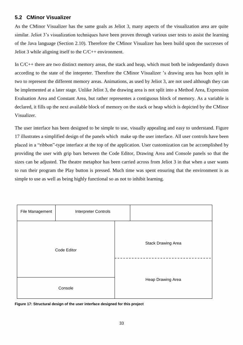
33
5.2 CMinor Visualizer
As the CMinor Visualizer has the same goals as Jeliot 3, many aspects of the visualization area are quite
similar. Jeliot 3‟s visualization techniques have been proven through various user tests to assist the learning
of the Java language (Section 2.10). Therefore the CMinor Visualizer has been build upon the successes of
Jeliot 3 while aligning itself to the C/C++ environment.
In C/C++ there are two distinct memory areas, the stack and heap, which must both be independantly drawn
according to the state of the intepreter. Therefore the CMinor Visualizer ‟s drawing area has been split in
two to represent the different memory areas. Animations, as used by Jeliot 3, are not used although they can
be implemented at a later stage. Unlike Jeliot 3, the drawing area is not split into a Method Area, Expression
Evaluation Area and Constant Area, but rather representes a contiguous block of memory. As a variable is
declared, it fills up the next available block of memory on the stack or heap which is depicted by the CMinor
Visualizer.
The user interface has been designed to be simple to use, visually appealing and easy to understand. Figure
17 illustrates a simplified design of the panels which make up the user interface. All user controls have been
placed in a “ribbon”-type interface at the top of the application. User customization can be accomplished by
providing the user with grip bars between the Code Editor, Drawing Area and Console panels so that the
sizes can be adjusted. The theatre metaphor has been carried across from Jeliot 3 in that when a user wants
to run their program the Play button is pressed. Much time was spent ensuring that the environment is as
simple to use as well as being highly functional so as not to inhibit learning.
Figure 17: Structural design of the user interface designed for this project
File Management Interpreter Controls
Code Editor
Console
Stack Drawing Area
Heap Drawing Area
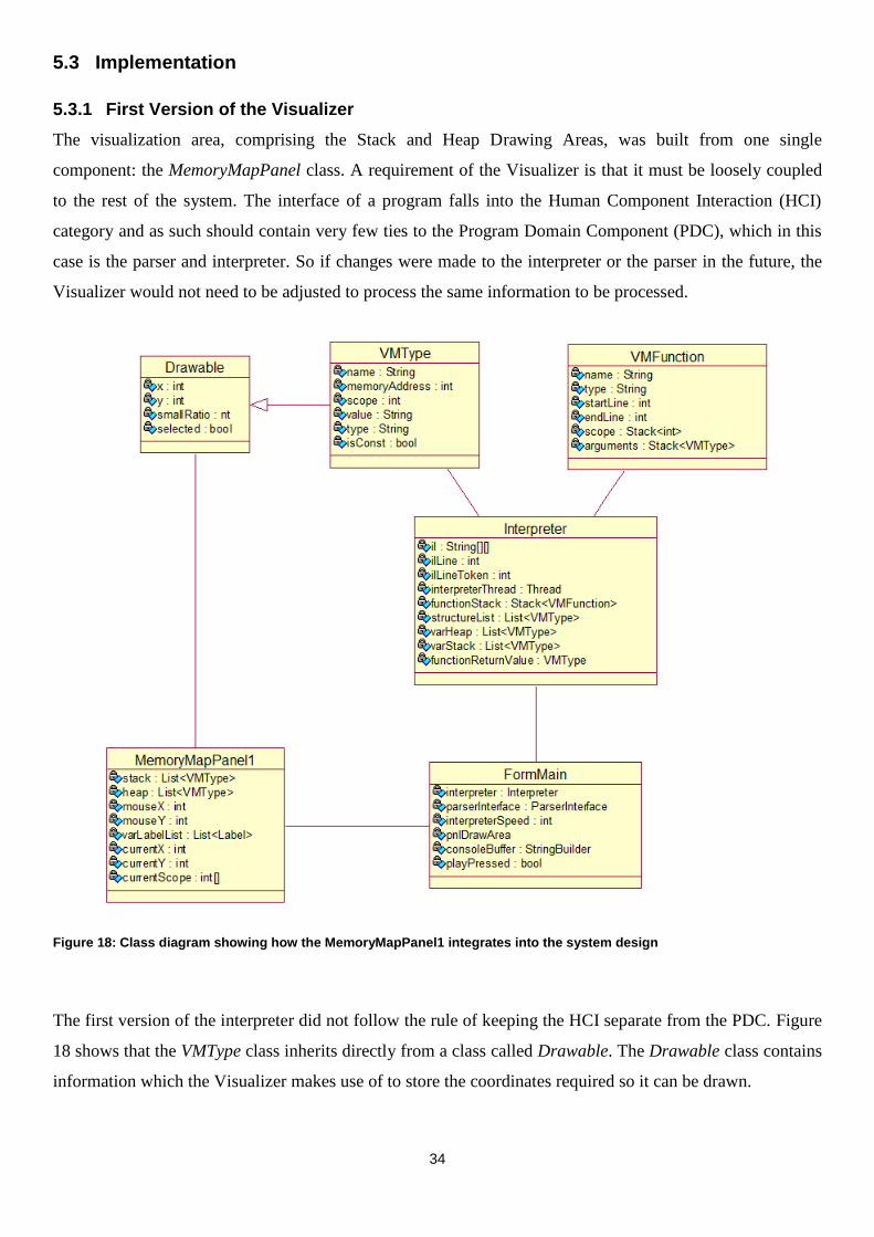
34
5.3 Implementation
5.3.1 First Version of the Visualizer
The visualization area, comprising the Stack and Heap Drawing Areas, was built from one single
component: the MemoryMapPanel class. A requirement of the Visualizer is that it must be loosely coupled
to the rest of the system. The interface of a program falls into the Human Component Interaction (HCI)
category and as such should contain very few ties to the Program Domain Component (PDC), which in this
case is the parser and interpreter. So if changes were made to the interpreter or the parser in the future, the
Visualizer would not need to be adjusted to process the same information to be processed.
Figure 18: Class diagram showing how the MemoryMapPanel1 integrates into the system design
The first version of the interpreter did not follow the rule of keeping the HCI separate from the PDC. Figure
18 shows that the VMType class inherits directly from a class called Drawable. The Drawable class contains
information which the Visualizer makes use of to store the coordinates required so it can be drawn.

35
Another link exists between the PDC and the HCI in this model through the interpreter. As a line of source
code is processed, a signal is sent to the Visualizer instructing the MemoryMapPanel to redraw itself. A
reference of the stack and heap lists are then sent to the Visualizer which processes the items within,
assigning the individual VMType objects coordinates through the Drawable class. If changes were to be
made to the interpreter, such as changing the visuals to 3D thus requiring a Z-coordinate, the Drawable class
would have to be modified which is not ideal as a program domain component would have to be modified
for an HCI change.
Performance was also an issue with this model, as one panel is responsible for the drawing of all the
components. Upon the Visualizer being signalled to redraw itself, the stack and heap lists must be traversed
twice in order to recalculate the variable‟s coordinates and then paint the individual components to the
screen. The problem with this is that recursion must be used as each VMType may be an array or structure.
Therefore, as each VMType object contains lists each holding additional VMType objects (Figure 12), these
lists must also be traversed. In turn the VMType objects within those lists could also be arrays or structures
containing additional lists which must be traversed, and so forth. Therefore the traversal of the stack and
heap lists is an expensive operation, especially with many objects in the heap and stack, and should be kept
to an absolute minimum. As the mouse is moved across the drawing surface, each list must be traversed in
order to determine if the mouse coordinates fall between the coordinates of a particular variable in order to
change its appearance. This is so the Visualizer can make the object “pop up” and show a floating panel with
the variable‟s particular details. However as the mouse is moved, the entire visual area must be repainted
which, as already discussed, is an expensive operation.
This method was implemented and worked sufficiently for small numbers of variables on-screen; however
with a large number of elements a noticeable slowdown became apparent due to all the list traversals. This
performance decline greatly hampered user interaction. Therefore another, more efficient method of
visualization was developed.

36
5.3.2 The Visualizer Redesigned
Figure 19: Class diagram illustrating the redesign of the human interaction component
To rectify the performance issues, a redesign of the Visualizer was necessary. Two separate components
were therefore developed (Figure 19). The second version of the MemoryMapPanel is responsible for
calculating the coordinates of the variables which reside in the heap and stack lists, as well as creating a list
of VMTypePanel objects mapping the required information from each of the VMType objects. The
VMTypePanel objects remove the need for the Drawable class in Section 5.3.1. By removing the Drawable
class, a decoupling takes place between the HCI and PDC which is ideal. The VMTypePanel class is
responsible for the painting of the variable, removing the responsibility from the MemoryMapPanel as well
as removing one of the recursive traversals of the heap and stack lists. By utilizing the OnMouseEnter and
OnMouseExit event methods of the VMTypePanel class there is no need to traverse the variable lists to
determine if the mouse coordinates fall between the bounds of a variable. This thereby removes another list

37
traversal as the VMTypePanel objects now raise certain events which determine whether they should redraw
themselves.
Through the decoupling of the various components as well as the reduction in list traversals there is a
noticeable performance increase. Overall, the number of list traversals has been reduced to one per signal
from the interpreter. A very responsive user interface is the outcome from the above mentioned changes.

38
6 CMinor Studio
CMinor Studio is the final product of this research and as such incorporates a working parser, interpreter and
Visualizer (Figure 20). The application provides an interactive development environment (IDE) with which
the user can program, run, debug and visualize the CMinor source code.

39
Figure 20: Screenshot of CMinor Studio
Figure 21: Pointer variables as depicted by the Visualizer

40
As a teaching tool, it provides syntax highlighting, ability to control the speed of interpretation of a program,
error tracing, input and output through a console as well as the visualization of variables on the stack and
heap.
Pointers and memory management (Section 2.8) are one of the main areas which students struggle to
comprehend. Therefore the main focus of the CMinor Studio application is to produce clear visuals with
regards to pointers, as can be seen in Figure 21. As a program can contain many variables and pointers, the
pointer lines are drawn with a very slight opacity to increase legibility. The pointer lines are drawn to a grid
which allows them to follow a direct route to their destination. To ensure an uncluttered visual, pointer lines
will never intersect the variables drawn on the screen.
Errors occur during the creation of programs, and as such the user must be notified. CMinor Studio provides
a clear description of the errors encountered and draws a red line where the error occurred (Figure 22) to
direct the user‟s attention to the erroneous part of the program.

41
Figure 22: Erroneous lines are highlighted in the code view and a corresponding message is given in the console
Figure 23: User interaction through movement of the mouse changes the visual produced

42
CMinor Studio provides the user with the ability to interact with the Visualizer. As the user moves their
mouse over a variable, it will “pop up” (Figure 23). This clearly shows which variable is currently under
inspection, which is useful for demonstration purposes. If the user hovers over a pointer variable, the opaque
line to the variable being pointed at will become solid. In a program with numerous variables, this
highlighting of the pointer line helps clearly identify the variables being pointed to. When hovering over a
variable for a certain period of time, a floating panel will appear just below the highlighted variable. This
panel displays all information concerning the variable being hovered over.
As functions are called, many new variables may be introduced which can fill up the visualization area
making it difficult for the user to focus on the variables currently in scope. Therefore as variables go out of
scope during the execution of a program, the Visualizer will change their opacity (Figure 24). By fading out
variables which have moved out of scope, the user is able to focus their attention on the applicable areas of
the visualization.

43
Figure 24: Variables not in the currently executing scope are faded out
Figure 25: Linked list representation by the Visualizer

44
The visualization of data structures was one of the main aims of this project. Data structures form an integral
part of many programs and as such are taught in various programming classes (Deitel & Deitel, 2003). For a
student to gain an understanding of a data structure, they must be able to visualize how the data structure is
being represented in memory as well as which variables are linked together. Through the user‟s ability to
interact with the visualization produced by the CMinor Studio, data structures can be easily grasped (Figure
25).
45
7 Conclusion
Developments within the field of SV are leading to pervasive adoption (Gracanin et al., 2005) for better
comprehension, engineering and enhancements within the field of algorithm animation, software evolution
and software metrics. A survey of software maintenance and engineering studies (Diehl, 2005) shows that
40% of researchers consider SV “absolutely necessary for their work”, while 42% of researchers find SV to
be “important but not critical”.
Education benefits arise due to the increasing amount of software written utilizing efficient and effective
visualization systems to provide an environment to facilitate the rapid adoption and reduced complexity of
learning new programming concepts and/or a new programming language. These benefits have been
evaluated by Ben-Bassat Levy et al. (2003) with the use of Jeliot 2000, and Grissom et al. (2003) and show
that due to the increased level of engagement, the student‟s vocabulary of programming verbal and visual
terms increases thereby improving comprehension of these terms and supporting discussions.
CMinor is a programming language which has been designed to be syntactically similar to and a subset of
C/C++ whilst reducing the complexity by excluding features not deemed necessary for a beginner. By
utilizing a simple language, the novice programmer is able to focus on the other aspects of programming
such as memory management, pointer handling and data structure assembly.
A translator has been designed to perform syntax and semantic checks on the source code entered by the
user. If no errors are found, the parser translates the source code into an intermediate language. The
intermediate language is a high-level and structured representation of the source code which is fed into the
interpreter. The interpreter is responsible for the execution of the user‟s program, as well as signalling the
Visualizer to draw the variables present on the heap and stack memory spaces. The interpreter makes two
passes over the resultant tokens from the intermediate language to initialize the data structures required for
the interpretation process and then to perform the interpretation process. The entire process from parsing
through to signalling the Visualizer is illustrated in Figure 26.

46
Figure 26: Overall operation of the system
The Visualizer produces a visual that represents contiguous memory blocks on the stack and heap. Through
a link to the program domain component (Figure 19), the interpreter‟s stack and heap is analysed to produce
a memory mapping of the variables contained inside. The visual is generated in such a way to as allow the
user easily to identify the variables currently in use by the interpreter, for example by fading out variables
not in the currently executing scope. User interaction is supported by moving the mouse over a particular
variable. This action “pops up” the variable making it easily discernable. If the mouse is positioned over a
pointer variable, the line which points to the referenced variable is drawn bolder so as to clearly show which
variables are active. This helps especially for the visualization of data structures as pointers within nodes can
easily be traced.
CMinor Studio is the integrated development environment (IDE) featuring a simplistic user environment
through which CMinor code is entered, parsed, interpreted and visualized. CMinor Studio provides the
following usability features:
Speed controls provide the user with the ability to change the interpreter execution speed.
The ability to pause interpreter execution in order to manually step through the code.
Function highlighting providing an uncomplicated means to follow code execution through various
function calls.
Syntax highlights, liner numbers and automatic tabbing in the code editor mimics a professional C/C++
IDE.
An error reporting facility provides detailed error messages and the ability to easily pin-point the
erroneous line of code.
User Interface Parser
Visualizer Interpreter
1. Source
Code
2. Generated
Intermediate Language
3. Program
Execution
4. User interacts
with the GUI

47
The Visualizer is limited by the interpreter and the CMinor language in what it can visualize. In order to
make the tool useful for intermediate programmers that require a greater set of features than what CMinor
currently offers, a possible extension to this project would be to add additional language features of C/C++.
Object oriented programming would enhance this project by providing additional functionality and teaching
possibilities. The current method of visualizing variables on the heap and stack would therefore have to be
redesigned in order to portray classes in a meaningful way. Another future extension could be an algorithmic
visual which is displayed by the Visualizer instead of a direct memory map of variables on the heap and
stack. Additional meta-data could be used by the interpreter to signal the Visualizer to, for example, build a
visual representing a binary tree or another structure (Figure 27).
Figure 27: Algorithmic representation of a Binary Tree and other structures as an extension to the Visualizer
A software visualization system has been successfully developed for a beginner C/C++ programmer that can
be utilized within a practical or demonstration environment. By utilizing the CMinor language, beginner
programmers are able to focus on core programming concepts. The aims of this project have thus been
accomplished through the creation of the CMinor Studio application, incorporating a fully functional parser,
interpreter and Visualizer, that provides an interactive 2D visual used to complement teaching methodology.

48
8 References
Aho, A., Sethi, R., & Ullman, J. (1986). Compilers: Principles, Techniques and Tools. Reading, MA:
Addison-Wesley.
Asokan, R. (2003). Automatic visualization of the version history of a software system in three dimensions.
Virginia Polytechnic Institute and State University, Virginia.
Ball, T., & Eick, S. (1996). Software visualization in the large. IEEE comput 29(4), (pp. 33-43).
Ben-Bassat Levy, R., Ben-Ari, M., & Uronen, P. (2003). The Jeliot 2000 program animation system.
Computers & Education 40 (1) , 15-21.
Burch, M., Diehl, S., & Weissgerber, P. (2005). Visual data mining in software archives. ACM symposium
on software visualization (pp. 37-46). New York: ACM Press.
Conti, G., & Abdullah, K. (2004). Passive visual fingerprinting of network attack tools. ACM Workshop on
visualization and data mining for computer security, (pp. 45-54).
Deitel, H., & Deitel, P. (2003). C++ How to Program. New Jersey: Pearson Education, Inc.
Diehl, S. (2005). Software Visualization. 27th Internation conference on Software engineering (pp. 718-
719). New York: ACM Press.
Domingue, J., & Mulholland, P. (1997). Staging software visualizations on the web. IEEE symposium on
visual languages, (pp. 364-371).
Eick, S., Graves, T., Karr, A., Mockus, A., & Schuster, P. (2002). Visualizing. IEEE Trans Softw Eng , pp.
396-412.
Eick, S., Steffen, J., & Summer, E. J. (1992). Seesoft: a tool for visualizing line oriented software statistics.
IEEE Trans Softw Eng 18(11), (pp. 957-968).
Ford, L. (1993). How programmers visualize programs. Department of Computer Science. Exeter, England:
University of Exeter.
Gall, H., Jazayeri, M., & Riva, C. (1999). Visualizing software release histories: The use of colour and third
dimensions. IEEE international conference on software maintenance.
GNU Project. (2008, September 4). GCC, The GNU Compiler. Retrieved October 2008, 10, from Free
Software Foundation: http://gcc.gnu.org/
Gracanin, D., Matkovic, K., & Eltoweissy, M. (2005). Software visualization. Springer-Verlag.

49
Grissom, S., McNally, M., & Naps, T. (2003). Algorithm visualization in CS education: comparing levels of
student engagement. ACM Symposium on software visualization, (pp. 87-94).
Hundhausen, C., Douglas, S., & Stasko, J. (2002). A meta-study of algorithm visualization effectiveness. J
Vis Lang Comput 13(3), (pp. 259-290).
Hutchins, M., & Gallagher, K. (1998). Improving visual impact analysis. International Conference on
software maintenane, (pp. 294-303).
Institut für Systemsoftware. (2008, September 23). The Compiler Generator Coco/R. Retrieved October 13,
2008, from http://www.ssw.uni-linz.ac.at/coco/
Knight, C., & Munro, M. (1999). Comprehension with[in] virtual environments visualizations. Proceedings
of the 7th international workshop on program comprehension, (pp. 4-11). Pittsburgh, PA.
Kolling, M., Quig, B., Patterson, A., & Rosenburg, J. (2003). The BlueJ system and its pedagogy. Journal of
Computer Science Education .
LaFollette, P., Korsh, J., & Sangwan, R. (2000). A visual interface for effortless animation of C/C++
programs. J Vis Lang Comput 11(1), (pp. 27-48).
Lanza, M. (2003). CodeCrawler: lessons learned in building a software visualization tool. 7th European
conference on software maintenance and reengineering, (pp. 409-418).
Lattu, M., Meisalo, V., & Tarhio, J. (2003). A vizualization tool as a demonstration aid. Computers &
Education 41 , 133-148.
Lintern, R., Michaud, J., Storey, M., & Wu, X. (2003). Plugging-in visualization: experiences integrating a
visualization tool with Eclipse. ACM symposium on software visualization (pp. 47-56). New York: ACM
Press.
Mackinlay, J. (1986). Automating the design of graphical presentations of relational information. ACM
Trans Graph 5(2), (pp. 110-141).
Maletic, J., Leigh, J., Marcus, A., & Dunlap, G. (2001). Visualizing object-oriented software in virtual
reality. 9th International workshop on program comprehension, (pp. 26-35). Toronto.
Maletic, J., Marcus, A., & Collard, M. (2002). A task oriented view of software visualization. Proceedings
of the 1st international workshop on visualizing software for understanding and analysis, (pp. 32-40).
Malloy, B., & Power, J. (2005). Exploiting UML dynamic object modeling for the visualization of C++
programs. ACM symposium on software visualization, (pp. 105-114).

50
Myller, N. (2004). The fundamental design issues of Jeliot 3. University of Joensuu.
Parr, T. (n.d.). Retrieved October 2008, 9, from ANTLR Parser Generator: http://www.antlr.org/
Price, B., Baecker, R., & Small, I. (1993). A principled taxonomy of software visualization. J Vis Lang
Comput 4(3), (pp. 211-266).
Roman, G., & Cox, K. (1993). A taxonomy of program visualization systems. IEEE Computer 26(12), (pp.
11-24).
Roman, G., & Cox, K. (1992). Program visualization: the art of mapping programs to pictures. 14th
Internation conference on Software Engineering (pp. 412-420). Melbourne: ACM Press.
Smith, M., & Munro, M. (2002). Runtime visualization of object oriented software. 1st Internation
workshop on visualizing software for understand and analysis, (pp. 81-89).
sourcenav NG development group. (2008). Source Navigator NG. Retrieved October 2008, 10, from
http://sourcenav.berlios.de/
Stasko, J. (1992). Three-dimensional computation visualization. College of Computing, Graphics,
Visualization and Usability Center. Atlanta: Georgia Institute of Technology.
Storey, M., Wong, K., Fracchia, F., & Muller, H. (1997). On integrating visualization techniques for
effective software exploration. IEE symposium on information visualization, (pp. 38-45). Pheonix, AZ.
Stroustrup, B. (1999). Learning Standard C++ as a new language. The C/C++ Users Journal , 1-5.
Stroustrup, B. (1997). The C++ Programming Language (3rd ed.). Michigan: Addison-Wesley.
Sun Microsystems. (2008, June 3). C/C++ Grammar by Sun Microsystems. Retrieved October 13, 2008,
from ANTLR Grammar List:
http://hg.netbeans.org/main/file/tip/cnd.modelimpl/src/org/netbeans/modules/cnd/modelimpl/parser/cpppars
er.g
Sun Microsystems. (2008, October 31). Netbeans IDE. Retrieved October 31, 2008, from Netbeans:
http://www.netbeans.org/
Sutinen, E., Tarhio, J., & Teravirta, T. (2003). Easy algorithm animation on the web. Multimedia tools and
applications 19(2) , 179-184.
Sutinen, E., Tarhio, J., Lahtinen, S., Tuovinen, A., Rautama, E., & Meisalo, V. (1997). Eliot - an Algorithm
Animation Environment. Retrieved 5 24, 2008, from http://www.cs.helsinki.fi/TR/A-1997/4/A-1997-4.ps.gz

51
Terry, P. (2005). Compiling with C# and Java. London: Pearson Education Limited.
Tilley, S., & Huang, S. (2002). On selecting software visualization tools for program understanding in an
industrial context. 10th International workshop on program comprehension, (pp. 285-288).
Tiobe Software. (2008, May 1). TIOBE Programming Community Index. Retrieved November 3, 2008, from
TIOBE Software: http://www.tiobe.com/index.php/content/paperinfo/tpci/index.html
van Ham, F. (2003). Using multilevel call matrices in large software projects. Proceedings of 2003 IEEE
symposium on information visualization, (pp. 227-232).
Ware, C., Hui, D., & Frank, G. (1993). Visualizing object oriented software in three dimensions. IBM
Center for Advanced Studies conference, (pp. 612-660). Toronto.

52
Appendix A: CMinor Studio User Manual

53
Appendix B: CMinor.h Listing
Function Summary
int rand()
Returns the next pseudorandom, uniformly distributed int
value from this random number generator's sequence.
bool readBool()
Reads the next token of the input from the console into a
boolean value and returns that value.
char readChar()
Reads the next token of the input from the console into a
char value and returns that value.
int readInt()
Reads the next token of the input from the console into an
int value and returns that value.
void write(Expression | String Constant {, Expression | String Constant})
Prints a variable number of expressions or string constants to the
console.
Example:
write(x + 10);
write(“sum”);
write(“sum is”, x + 10);
void writeLine(Expression | String Constant {, Expression | String Constant})
Prints a variable number of expressions or string constants to the
console and appends a newline character.
Example:
writeLine(x + 10);
writeLine(“sum”);
writeLine(“sum is”, x + 10);

54
Appendix C: CMinor Unattributed Grammar
COMPILER CMinor $NC
CHARACTERS
lf = CHR(10) .
cr = CHR(13) .
backslash = CHR(92) .
control = CHR(0) .. CHR(31) .
letter = "ABCDEFGHIJKLMNOPQRSTUVWXYZabcdefghijklmnopqrstuvwxyz" .
digit = "0123456789" .
stringCh = ANY - '"' - control - backslash .
charCh = ANY - "'" - control - backslash .
printable = ANY - control .
TOKENS
identifier = letter { letter | digit | "_" } .
number = digit { digit } .
stringLiteral = '"' { stringCh | backslash printable } '"' .
charLiteral = "'" ( charCh | backslash printable ) "'" .
eol = cr lf.
COMMENTS FROM "//" TO lf
COMMENTS FROM "/*" TO "*/"
IGNORE CHR(9) .. CHR(13)
PRODUCTIONS
CMinor
= {
StructDeclaration
| ConstDeclarations
| FunctionOrVarDeclarations
| "#include" stringLiteral
} EOF
.
StructDeclaration
= "struct" Ident
"{"
( ConstDeclarations
| StructFieldDeclarations
) SYNC
{
( ConstDeclarations
| StructFieldDeclarations
) SYNC
}
"}"
WEAK ";"
.
ConstDeclarations
= ( "const"
)
BasicType
OneConst
WEAK ";"
.

55
OneConst
= Ident
AssignOp
Expression
.
Constant
= IntConst
| CharConst
| "true"
| "false"
| "NULL"
.
FunctionOrVarDeclarations
= IdentType Ident
(
"("
[ ParamList ]
")"
"{" StatementList
"}"
|
( "[" (
Expression
|
)
WEAK "]"
| AssignOp
Expression
| )
{ WEAK ","
Ident
( "[" (
Expression
|
)
WEAK "]"
| AssignOp
Expression
| )
} WEAK ";"
) .
StructFieldDeclarations
= IdentType Ident
( "[" (
Expression
|
)
WEAK "]"
| )
{ WEAK "," Ident
( "[" (
Expression
|
)
WEAK "]"
| )
}
WEAK ";"
.
ParamList
= OneParam

56
{ WEAK ","
OneParam
} .
OneParam
= IdentType
Ident
[ "["
"]"
]
.
IdentType
= SimpleType
| "void"
.
SimpleType
= BasicType
| Ident
["*"
]
.
BasicType
= ((( "int"
| "char"
)
[PointerType]
)
| "bool"
)
.
PointerType
= "*"
.
StatementList
= { Statement
SYNC
} .
Statement
= Block
| AssignCallObjDecl
| IfStatement
| IterationStatement
| JumpStatement
| OutputStatement
| ConstDeclarations
| VarDeclarations
| DeleteStatement
| ";"
.
Block
= "{" StatementList
"}"
.
AssignCallObjDecl
=
["*"
]
["("
]
Designator
[")"
]

57
(
( AssignOp
Expression
)
|
"("
Arguments
")"
|
["*"
]
OneVar
{ WEAK ","
["*"
]
OneVar }
|
)
WEAK ";" .
VarDeclarations
=
BasicType
OneVar
{ WEAK ","
[PointerType]
OneVar }
WEAK ";"
.
OneVar
= Ident
( "["
Expression
WEAK "]"
[ AssignOp
(StringConst
|
"{"
(Expression
{ ","
Expression
}
| ","
|
)
WEAK "}"
)
]
| AssignOp
Expression
|
)
.
Designator
= Ident
{ "."
Ident
| HeapDerefOp
Ident
| "["
Expression
"]"
}
.

58
IfStatement
= "if"
"(" Condition WEAK ")"
Statement
[ "else"
Statement
] .
IterationStatement
= WhileStatement | DoWhileStatement | ForStatement
.
WhileStatement
= "while"
"(" Condition WEAK ")"
Statement
.
DoWhileStatement
= "do"
Statement
"while" WEAK "("
Condition
")" WEAK ";" .
ForStatement
= "for" WEAK "(" ForInitStatement
[ Condition ] ";"
[ ForExpression {"," ForExpression } ]
WEAK ")" SYNC Statement
.
ForInitStatement
= AssignCallObjDecl | VarDeclarations | ";"
.
ForExpression
= ["*"] Designator
(
( AssignOp Expression | "++" | "--"
)
)
.
JumpStatement
= ContinueStatement | ReturnStatement | BreakStatement
.
ContinueStatement
= "continue"
WEAK ";"
.
BreakStatement
= "break"
WEAK ";" .
ReturnStatement
= "return"
(
Expression
|
)
WEAK ";" .
DeleteStatement
= "delete"
["[""]"
]
Designator

59
WEAK ";"
.
ReadStatement
=
( "readInt"
| "readChar"
| "readBool"
)
"(" WEAK ")"
.
OutputStatement
= WriteStatement | WriteLineStatement
.
WriteLineStatement
= "writeLine"
"("
[WriteElement] ")"
WEAK ";"
.
WriteStatement
= "write"
"(" WriteElement ")"
WEAK ";"
.
WriteElement
= ( Expression
| StringConst
)
{ WEAK ","
(Expression
| StringConst
)
}
.
Arguments
= [
ArgList ]
.
ArgList
= OneArg
{ WEAK ","
OneArg
} .
OneArg
= Expression
.
Condition
=
Expression
.
Expression
=
AndExp
{ "||"
AndExp

60
}
.
AndExp
= EqlExp
{ "&&"
EqlExp
} .
EqlExp
= RelExp
[ EqlOp RelExp
] .
RelExp
= AddExp
[ RelOp AddExp
] .
AddExp
= MulExp
{ AddOp MulExp
} .
MulExp
= Factor
{ MulOp Factor
} .
Factor
= Primary
| "+"
Factor
| "-"
Factor
| "!"
Factor
.
Primary
= Designator
(
"("
Arguments ")"
| "++"
| "--"
|
)
| Constant
| "("
Expression ")"
| AddressOf
| Dereference
| HeapAllocation
| ReadStatement
| "rand" "(" ")"
.
HeapAllocation
= "new"
( "int"
| "char"
| Ident
)
( "["(
Expression
|
)
"]"
|

61
"("
[
Expression
]
")"
|
)
.
Dereference
= "*"
("(" Expression
")"
| Ident
[ "["
Expression
"]" ]
)
.
AddressOf
= "&"
Designator
.
AssignOp
= "="
| ":="
.
HeapDerefOp
= "->"
.
EqlOp
= "=="
| "!="
.
RelOp
= ">"
| ">="
| "
= "+"
| "-"
.
MulOp
= "*"
| "/"
| "%"
.
Ident
= ( identifier
) .
CharConst
= charLiteral
.
IntConst
= number
.
StringConst
= stringLiteral
.
END CMinor.

62
Appendix D: Poster