Embed Size (px)
Citation preview

INTERSECTION GEOMETRIC DESIGN
By: Gregory J. Taylor, P.E.
PDHLibrary Course No 0010089 6 PDH HOURS

INTERSECTION GEOMETRIC
DESIGN
by
Gregory J. Taylor, P.E.
Intersection Geometric Design
Copyright 2015 Gregory J.
Taylor, P.E. Page 2 of 64
INTRODUCTION
This course summarizes and highlights the geometric design process for modern
roadway intersections. The contents of this document are intended to serve as guidance
and not as an absolute standard or rule.
When you complete this course, you should be familiar with the general guidelines for
at-grade intersection design. The course objective is to give engineers and designers an
in-depth look at the principles to be considered when selecting and designing
intersections.
Subjects include:
General design considerations � function, objectives, capacity
Alignment and profile
Sight distance � sight triangles, skew
Turning roadways � channelization, islands, superelevation
Auxiliary lanes
Median openings � control radii, lengths, skew
Left turns and U-turns
Roundabouts
Miscellaneous considerations � pedestrians, traffic control, frontage roads
Railroad crossings � alignments, sight distance
For this course, Chapter 9 of A Policy on Geometric Design of Highways and Streets
(also known as the �Green Book�) published by the American Association of State
Highway and Transportation Officials (AASHTO) will be used primarily for
fundamental geometric design principles. This text is considered to be the primary
guidance for U.S. roadway geometric design.

Intersection Geometric Design
Copyright 2015 Gregory J.
Taylor, P.E. Page 3 of 64
This document is intended to explain some principles of good roadway design and
show the potential trade-offs that the designer may have to face in a variety of
situations, including cost of construction, maintenance requirements, compatibility with
adjacent land uses, operational and safety impacts, environmental sensitivity, and
compatibility with infrastructure needs.
Geometric design is the assembly of the fundamental three-dimensional features of the
highway that are related to its operational quality and safety. Its basic objective is to
provide a smooth-flowing, crash-free facility. Geometric roadway design consists of
three main parts: cross section (lanes and shoulders, curbs, medians, roadside slopes
and ditches, sidewalks); horizontal alignment (tangents and curves); and vertical
alignment (grades and vertical curves). Combined, these elements provide a three-
dimensional layout for a roadway.
Effective geometric design transmits knowledge from research and operational
experience to the user. It reflects both human and vehicular characteristics and
capabilities.
The practice of geometric design will always be a dynamic process with a multitude of
considerations: driver age and abilities; vehicle fleet variety and types; construction
costs; maintenance requirements; environmental sensitivity; land use; aesthetics; and
most importantly, societal values.

Intersection Geometric Design
Copyright 2015 Gregory J.
Taylor, P.E. Page 4 of 64
Despite this dynamic character, the primary objective of good design will remain as it
has always been � to provide a safe, efficient and cost-effective roadway that
addresses conflicting needs or concerns.
INTERSECTIONS Intersections are unique roadway elements where conflicting vehicle streams (and
sometimes non-motorized users) share the same space. This area encompasses all
modes of travel - pedestrian
bicycle
passenger vehicle
truck
transit
as well as auxiliary lanes, medians, islands, sidewalks and pedestrian ramps. These may
further heighten the accident potential and constrain the operational efficiency and
network capacity of the urban street system. However, the main objective of intersection
design is to facilitate the roadway user and enhance efficient vehicle movement. The need to
provide extra time for drivers to perceive, decide, and navigate through the intersection
is central to intersection design controls and practices.
Intersection Geometric Design
Copyright 2015 Gregory J.
Taylor, P.E. Page 5 of 64
Designing to accommodate the appropriate traffic control are critical to good
intersection design. Warrants and guidelines for selection of appropriate intersection
control (including stop, yield, all-stop, or signal control) may be found in the MUTCD.
Basic Elements of Intersection Design
Human Factors
Driver habits, decision ability, driver expectancy, decision/reaction time, paths of
movement, pedestrian characteristics, bicyclists
Traffic Considerations
Roadway classifications, capacities, turning movements, vehicle characteristics, traffic
movements, vehicle speeds, transit, crash history, bicycles, pedestrians
Physical Elements
Abutting properties, vertical alignments, sight distance, intersection angle, conflict area,
speed-change lanes, geometric design, traffic control, lighting, roadside design,
environmental factors, crosswalks, driveways, access management
Economic Factors
Improvement costs, energy consumption, right-of-way impacts
A range of design elements are available to achieve the functional objectives, including
horizontal and vertical geometry, left- and right-turn lanes, channelization, etc.
Level of service analysis and roadway capacity are critical considerations in intersection
design. Capacity is determined by constraints at intersections. Vehicle turns at
intersections interrupt traffic flow and reduce levels of service.
AASHTO defines intersection capacity as �the maximum hourly rate at which vehicles
can reasonably be expected to pass through the intersection under prevailing traffic,
roadway, and signalization conditions�. The Highway Capacity Manual (HCM)
provides various analysis techniques for comparing different conditions at
intersections.

Intersection Geometric Design
Copyright 2015 Gregory J.
Taylor, P.E. Page 6 of 64
A well-designed intersection is clear to the driver with design dimensions supporting
operational requirements, traffic control devices functioning as intended, and
nonmotorized vehicle users operating safely through the intersection.
Basic Types of Intersections
Three-leg (T)
Four-leg
Multi-leg
Roundabout
These types may vary based on scope, shape, flaring (for auxiliary lanes), and
channelization (separation/regulation of conflicting traffic).
Variables for determining the type of intersection to be used at a location include:
Topography
Traffic characteristics
Number of legs

Intersection Geometric Design
Copyright 2015 Gregory J.
Taylor, P.E. Page 7 of 64
Type of operation
Roadway character
Three-leg
The typical three-leg intersection configuration contains normal paving widths with
paved corner radii for accommodating design vehicles. The angle of intersection
typically ranges from 60 to 120 degrees.
Auxiliary lanes (left or right-turn lanes) may be used to increase roadway capacity and
provide better operational conditions.
Channelization may be achieved by increasing corner radii to separate a turning
roadway from the normal traveled ways by an island.
Four-leg
Many of the three-leg intersection design considerations (islands, auxiliary lanes,
channelization, etc.) may also be applied to four-leg intersections.
Multi-leg
Intersection designs with multiple legs (5 or more) should not be used unless there is no
other viable alternative. If multi-legs must be used, a common paved area where all legs
intersect may be desirable for light traffic volumes and stop control.
Operational efficiency can also be increased by removing major conflicting movements.
Multi-leg Reconfiguration Options
Realigning one or more legs
Combining traffic movements at subsidiary intersections
Redesigning as a roundabout
Converting legs to one-way operation

Intersection Geometric Design
Copyright 2015 Gregory J.
Taylor, P.E. Page 8 of 64
Alignment and Profile
Roadway geometry influences its safety performance. This has been confirmed by
research showing that roadway factors are the second most contributing factor to
roadway crashes. In the U.S., the average crash rate for horizontal curves is about three
times that of other highway segments.
Conflicts tend to occur more frequently on roadways with sudden changes in their
character (i.e. sharp curves at the end of long tangent roadway sections). The concept of
design consistency compares adjacent road segments and identifies sites with changes
that might appear sudden or unexpected. Design consistency analysis can be used to
show the decrease in operating speed at a curve.
The horizontal and vertical geometries are the most critical design elements of any
roadway. While most designers normally design the horizontal and then the vertical
alignment, these should be coordinated to enhance vehicle operation, uniform speed,
and facility appearance without additional costs (checking for additional sight distance
prior to major changes in the horizontal alignment; revising design elements to

Intersection Geometric Design
Copyright 2015 Gregory J.
Taylor, P.E. Page 9 of 64
eliminate potential drainage problems; etc.). Computer-aided design (CAD) is the most
popular method used to facilitate the iterative three-dimensional design and coordinate
the horizontal and vertical alignments.
The location of a roadway may be determined by traffic, topography, geotechnical
concerns, culture, future development, and project limits. Design speed limits many
design values (curves, sight distance) and influences others (width, clearance,
maximum gradient).
Intersecting roads should be aligned at approximate right angles in order to reduce
costs and potential crashes. Intersections with acute angles need larger turning areas,
limit visibility, and increase vehicle exposure time. Although minor road intersections
with major roads are desired to be as close to 90 degrees as practical, some deviation is
allowable � angles of 60 degrees provide most of the benefits of right angle intersections
(reduced right-of-way and construction costs).
Vertical grades that impact vehicle control should be avoided at intersections. Stopping
and accelerating distances calculated for passenger vehicles on 3 percent maximum
grades differ little from those on the level. Grades steeper than 3 percent may require
modifications to different design elements to match similar operations on level
roadways. Therefore, avoid grades for intersecting roads in excess of 3 percent within
intersection areas unless cost prohibitive � then a maximum limit of 6 percent may be
permissible.
AASHTO provides the following general design guidelines regarding horizontal and
vertical alignment combinations:
Vertical and horizontal elements should be balanced. A design which optimizes
safety, capacity, operation, and aesthetics within the location�s topography is
desirable.

Intersection Geometric Design
Copyright 2015 Gregory J.
Taylor, P.E. Page 10 of 64
Horizontal and vertical alignment elements should coincide to provide a
pleasing facility for roadway traffic.
Avoid sharp horizontal curves near the top of a crest vertical curve or near the
low point of a sag vertical curve. This condition may violate driver expectations.
Using higher design values (well above the minimum) for design speed can
produce suitable designs.
Horizontal and vertical curves should be flat as possible for intersections with
sight distance concerns.
For divided roadways, it may be suitable to vary the median width or use
independent horizontal/vertical alignments for individual one-way roads.
Roadway alignments should be designed to minimize nuisance in residential
areas. Measures may include: depressed facilities (decreases facility visibility and
noise), or horizontal adjustments (increases buffer zones between traffic and
neighborhoods).
Horizontal and vertical elements should be used to enhance environmental
features (parks, rivers, terrain, etc.). The roadway should lead into outstanding
views or features instead of avoiding them where possible.
Exception
Long tangent sections for sufficient passing sight distance may be appropriate for two-
lane roads needing passing sections at frequent intervals.
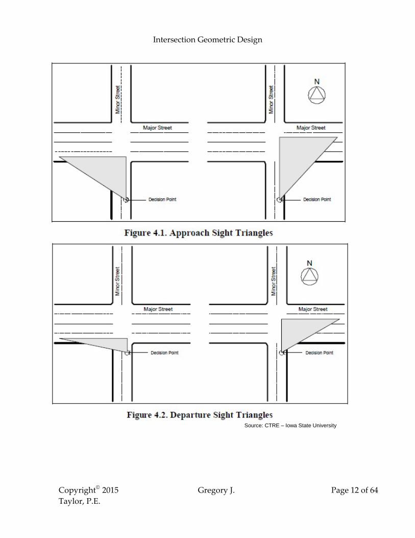
INTERSECTION SIGHT DISTANCE
Intersection sight distance is the length of roadway along the intersecting road for the
driver on the approach to perceive and react to the presence of potentially conflicting

Intersection Geometric Design
Copyright 2015 Gregory J.
Taylor, P.E. Page 11 of 64
vehicles. Drivers approaching intersections should have a clear view of the intersection
with adequate roadway to perceive and avoid potential hazards. Sight distance should
also be provided to allow stopped vehicles a sufficient view of the intersecting roadway
in order to enter or cross it. Intersection sight distances that exceed stopping sight
distances are preferable along major roads to enhance traffic operations. Methods for
determining intersection sight distances are based on many of the same principles as
stopping sight distance.
Source: CTRE � Iowa State University
Sight triangles are areas along intersection approach legs that should be clear of
obstructions that could block a driver�s view. The dimensions are based on driver
behavior, roadway design speeds, and type of traffic control. Object height (3.50 feet
above the intersecting roadway surface) is based on vehicle height of 4.35 feet
(representing the 15th percentile of current passenger car vehicle heights). The height of
the driver�s eye is typically assumed to be 3.50 feet above the roadway surface.
Intersection Geometric Design
Copyright 2015 Gregory J.
Taylor, P.E. Page 12 of 64
Source: CTRE � Iowa State University

Intersection Geometric Design
Copyright 2015 Gregory J.
Taylor, P.E. Page 13 of 64
Recommended sight triangle dimensions vary for the following different types of traffic
control:
Case A: Intersections with no control
Case B: Intersections with stop control on the minor road
o Case B1: Left turn from the minor road
o Case B2: Right turn from the minor road
o Case B3: Crossing maneuver from the minor road
Case C: Intersections with yield control on the minor road
o Case C1: Crossing maneuver from the minor road
o Case C2: Left or right turn from the minor road
Case D: Intersections with traffic signal control
Case E: Intersections with all-way stop control
Case F: Left turns from the major road
Section 9.5.3 of the AASHTO �Green Book� presents specific procedures for determining sight distances in each case.
Intersection Geometric Design
Copyright 2015 Gregory J.
Taylor, P.E. Page 14 of 64
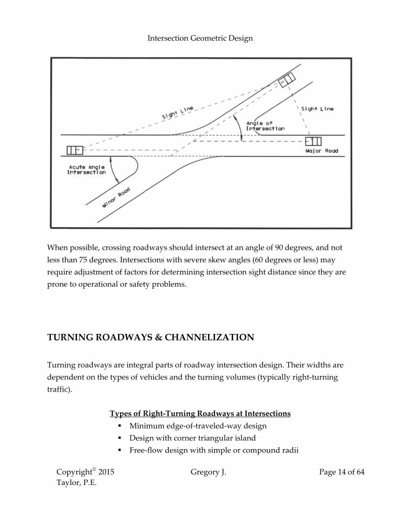
When possible, crossing roadways should intersect at an angle of 90 degrees, and not
less than 75 degrees. Intersections with severe skew angles (60 degrees or less) may
require adjustment of factors for determining intersection sight distance since they are
prone to operational or safety problems.
TURNING ROADWAYS & CHANNELIZATION
Turning roadways are integral parts of roadway intersection design. Their widths are
dependent on the types of vehicles and the turning volumes (typically right-turning
traffic).
Types of Right-Turning Roadways at Intersections
Minimum edge-of-traveled-way design
Design with corner triangular island
Free-flow design with simple or compound radii
Intersection Geometric Design
Copyright 2015 Gregory J.
Taylor, P.E. Page 15 of 64
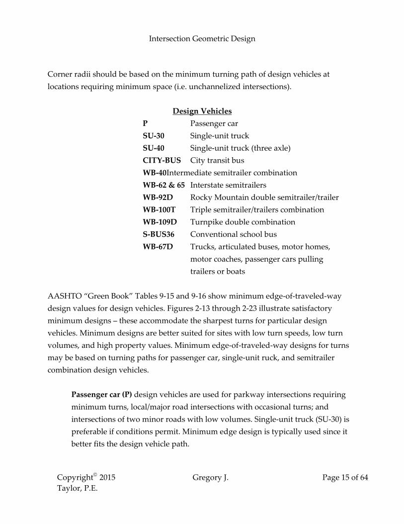
Corner radii should be based on the minimum turning path of design vehicles at
locations requiring minimum space (i.e. unchannelized intersections).
Design Vehicles
P Passenger car
SU-30 Single-unit truck
SU-40 Single-unit truck (three axle)
CITY-BUS City transit bus
WB-40 Intermediate semitrailer combination
WB-62 & 65 Interstate semitrailers
WB-92D Rocky Mountain double semitrailer/trailer
WB-100T Triple semitrailer/trailers combination
WB-109D Turnpike double combination
S-BUS36 Conventional school bus
WB-67D Trucks, articulated buses, motor homes,
motor coaches, passenger cars pulling
trailers or boats
AASHTO �Green Book� Tables 9-15 and 9-16 show minimum edge-of-traveled-way
design values for design vehicles. Figures 2-13 through 2-23 illustrate satisfactory
minimum designs � these accommodate the sharpest turns for particular design
vehicles. Minimum designs are better suited for sites with low turn speeds, low turn
volumes, and high property values. Minimum edge-of-traveled-way designs for turns
may be based on turning paths for passenger car, single-unit ruck, and semitrailer
combination design vehicles.
Passenger car (P) design vehicles are used for parkway intersections requiring
minimum turns, local/major road intersections with occasional turns; and
intersections of two minor roads with low volumes. Single-unit truck (SU-30) is
preferable if conditions permit. Minimum edge design is typically used since it
better fits the design vehicle path.

Intersection Geometric Design
Copyright 2015 Gregory J.
Taylor, P.E. Page 16 of 64
Single-unit truck (SU-30 and SU-40) vehicles are recommended for minimum
edge-of-traveled-way design for rural highways. Crucial turning movements
(major highway, large truck volume, etc.) may require speed-change lanes and/or
larger radii. Minimum travel way designs for single-unit trucks will also
accommodate city transit buses.
Semitrailer combination (WB series) design vehicles are used at locations with
repetitive truck combination turns. An asymmetrical setup of three-centered
compound curves is better suited for sites with large volumes of smaller truck
combinations. Semitrailer combination designs may need larger radii and corner
triangular islands due to their large paved areas.
Corner radii for urban arterial intersections should satisfy - driver needs, available
right-of-way, angle of turn, pedestrians using the crosswalk, number/width of traffic
lanes, and posted speeds.
Channelization
Channelization uses pavement markings and/or traffic islands to define definite travel
paths for conflicting traffic. Appropriate channelization not only increases capacity and
guides motorists but may also produce significant crash reductions and operational
efficiencies.
Design Controls for Channelized Intersections
Type of design vehicle
Crossroads cross sections
Projected traffic volumes
Number of pedestrians
Vehicle speed
Bus stop locations
Traffic control devices

Intersection Geometric Design
Copyright 2015 Gregory J.
Taylor, P.E. Page 17 of 64
Principles of Channelization
Do not confront motorists with more than one decision at a time
Avoid turns greater than 90 degrees or sharp/sudden curves
Reduce areas of vehicle conflict as much as possible
Traffic streams that intersect without merging/weaving should intersect at
approximately 90 degrees (60° to 120° acceptable)
Turning roadways should be controlled with a minimum intersection angle of 60
degrees where distances to downstream intersections is less than desirable
Angles of intersection between merging traffic streams should provide adequate
sight distance
Provide separate refuge areas for turning vehicles
Channelization islands should not interfere with bicycle lanes
Prohibited turns should be blocked by channelizing islands
Traffic control devices should be used as part of the channelized intersection
design
Further information regarding channelization devices can be found in the MUTCD and
Chapter 10 of the AASHTO �Green Book�.
Islands
Islands are designated areas between roadway lanes used for pedestrian sanctuary and
traffic control. Channelized intersections use islands to direct entering traffic into
definite travel paths. There is no single physical island type within an intersection �
they may be in the form of medians and outer separations or raised curbs and
pavement markings.
The primary functions of islands include:
Channelization - Directing and controlling traffic movements
The shape and size of these islands depend on the conditions and dimensions of the
intersection. Corner triangular islands used for separating right-turning traffic from

Intersection Geometric Design
Copyright 2015 Gregory J.
Taylor, P.E. Page 18 of 64
through vehicles are the most common form. The proper course of travel should be
obvious, easy to follow, and continuous.
Division - Dividing directional traffic streams
These islands at intersections alert drivers to any upcoming crossroads and regulate
traffic. Divisional islands are advantageous for controlling left turns and separating
roadways for right turns.
Refuge - Providing pedestrian sanctuary
These islands are located near crosswalks or bike paths to aid and protect users who cross
the roadway. Urban refuge islands are typically used for pedestrian/bicycle crossings for
wide streets, transit rider loading zones, or wheelchair ramps. Their size and location
depend on crosswalk location and width, transit loading sites and size, and provisional
handicap ramps.
Purposes of Channelizing Islands for Intersection Design
Separating traffic conflicts
Controlling conflict angles
Reducing excessive paving
Regulating roadway traffic
Supporting predominant traffic movements
Protecting pedestrians
Locating traffic control devices
Protecting/storing turning and crossing vehicles
Islands are typically elongated or triangular and placed out of vehicle paths. Curbed
islands for intersections need to have appropriate lighting or delineation. Painted, flush
medians/islands, or transversable medians may be used under certain conditions
unsuited for curbs (high speeds, snow areas, small pedestrian volume, few signals,
signs, or lights).

Intersection Geometric Design
Copyright 2015 Gregory J.
Taylor, P.E. Page 19 of 64
Island shapes and sizes differ from one intersection to another. These should be large
enough to command attention.
Minimum Curbed Corner Island Area
Urban Intersection 50 ft²
Rural Intersection 75 ft²
Preferable 100 ft² The sides of corner triangular islands should be a minimum of 12 feet (preferably 15
feet).
Elongated or divisional islands should be a minimum of 4 feet wide and 20 to 25 feet
long. These island widths may be reduced to 2 feet where space is limited.
Curbed divisional islands for high speed isolated intersections should be a minimum of
100 feet in length.
AUXILIARY LANES
Auxiliary lanes are typically used for median openings or intersections with right/left-
turning movements to increase capacity and reduce crashes.
A minimum auxiliary lane width of 10 feet is desirable and should be equivalent to that
for through lanes. Roadway shoulders should also have the same width as adjacent
shoulders (6 feet preferred � rural high speed roads). Shoulder widths can be reduced
or eliminated in many cases (urban areas, turn lanes, etc.). Paved shoulders of 2 to 4 feet
may be required for auxiliary lane locations with heavy vehicle usage or offtracking.
While there are no definite warrants for auxiliary lanes � factors such as roadway
capacity, speed, traffic volume, truck percentage, roadway type, right-of-way availability, level of
service, and intersection configuration should be considered.

Intersection Geometric Design
Copyright 2015 Gregory J.
Taylor, P.E. Page 20 of 64
General Auxiliary Lane Guidance
Auxiliary lanes are needed for high-speed, high volume roadways where a speed
change is required for entering/exiting vehicles
Directional auxiliary lanes with long tapers is adequate for typical driver
behavior
Drivers do not use auxiliary lanes the same way
The majority of motorists use auxiliary lanes during periods of high volume
Deceleration lanes prior to intersections may also be used successfully as storage
lanes for turning traffic
DECELERATION LANES
The physical length for a deceleration lane is broken down into the following
components:
Entering taper length (L₂)
Deceleration length (L₃)
Storage length (L₄)
Moderate rates of deceleration are typically accepted within the through lanes with
taper lengths considered as a part of the deceleration.

Intersection Geometric Design
Copyright 2015 Gregory J.
Taylor, P.E. Page 21 of 64
Table 9-22 (AASHTO Green Book) shows the estimated distances needed for
maneuvering into a turn bay and braking to a complete stop. These values range from
70 feet at 20 mph to 820 feet at 70 mph. A speed differential of 10 mph is considered
acceptable for turning vehicles and through traffic on arterial roadways. Higher speed
differentials may be okay for collector roads or streets with slow speeds or higher
volumes.
Signalized Intersection Storage Length Factors
o Intersection traffic analysis
o Spiral cycle length
o Signal phasing arrangement
o Arrivals/departures of left-turning vehicles
Storage length should be based on 1 ½ to 2 times the average number of stored vehicles
per cycle (from design volume).

Intersection Geometric Design
Copyright 2015 Gregory J.
Taylor, P.E. Page 22 of 64
The storage length for unsignalized intersections should also be determined by an
intersection traffic analysis. However, this analysis needs to be based on turning
vehicles arriving during an average two-minute period within the peak hour.
Provisions should be made for: minimum storage of 2 passenger cars; 10% turning truck
traffic; and storing at least one car and one truck.
LEFT-TURN LANE DESIGN
The accommodation of left-turning traffic is the single most important consideration in
intersection design. The principal controls for intersection type and design are:
Design-hour traffic volume Traffic character/composition Design speed
Traffic volume (actual/relative traffic volumes for turning and through movements) is
considered to be the single most significant factor in determining intersection type.
For intersection design, left-turning traffic in through lanes should be avoided, if
possible. Left-turn facilities on roadways are typically used to provide reasonable
service levels for intersections. Historically, using left-turn lanes has shown to reduce
crash rates 20 to 65%.
Various left-turn guidelines (Highway Capacity Manual, Highway Research Record
211, NCHRP Reports 255 and 279) are based on:
number of arterial lanes
design/operating speeds
left-turn volumes
opposing traffic volumes

Intersection Geometric Design
Copyright 2015 Gregory J.
Taylor, P.E. Page 23 of 64
The type of intersection is influenced by roadway design designation, traffic service,
right-of-way costs, and physical conditions.
The number of crossroads and intersecting roads should be minimized to benefit
through-traffic.
Median left-turn lanes are supplementary lanes used for storage or speed changes of
left-turning vehicles within medians or traffic islands. These lanes should be used at
locations with high left turn volumes or high vehicle speeds.
Intersections Median Width
Single median lane 20-ft minimum Desirable
16 to 18 feet Adequate
Two median lanes 28-ft minimum Desirable
(two 12-ft lanes with 4-ft separator)
The type of median end treatment adjacent to opposing traffic is dependent on available
width. Narrowed medians can be used to:
Separate opposing traffic
Protect pedestrians

Intersection Geometric Design
Copyright 2015 Gregory J.
Taylor, P.E. Page 24 of 64
Provide space for safety measures
Highlight lane edges
Minimum Narrowed Median Width*
4 ft (recommended)
6 to 8 ft (preferable)
*For medians 16 to 18 ft wide with a 12 ft turning lane
It is preferable to offset left-turn lanes for medians wider than 18 feet. This will reduce
the divider width to 6 to 8 feet prior to the intersection and prevent lane alignments
parallel or adjacent to the through lanes.
Advantages of Offset Left-turn Lanes
Better sight distance
Decreased turning conflict possibility
Increased left-turn traffic efficiency
The two main types of offset left-turn lane configurations used are parallel and tapered.

Intersection Geometric Design
Copyright 2015 Gregory J.
Taylor, P.E. Page 25 of 64
Parallel offset lanes are parallel but offset to the roadway�s through lanes while tapered
offset lanes diverge from the through lanes and cross the median at a slight angle. These
offset lanes should be used in conjunction with painted or raised channelization. While
both configurations are used for signalized intersections, parallel offset left-turn lanes
may also be suitable for unsignalized ones.
Double and triple turn lanes should only be for signalized intersection locations with
separate turning phases. It is recommended that the receiving intersection leg be able to
accommodate two lanes of turning vehicles (typically 30 feet). A 90-ft turning radius is
preferable for accommodating design vehicles (P through WB-40) within a swept path

Intersection Geometric Design
Copyright 2015 Gregory J.
Taylor, P.E. Page 26 of 64
width of 12 feet. Pavement markings may be used throughout the intersection to
provide visual cues.
MEDIAN OPENINGS
Median openings should be consistent with site characteristics, through/turning traffic
volumes, type of turning vehicles, and signal spacing criteria. For locations with low
traffic volumes where the majority of vehicles travel on the divided roadway, the
simplest and most economic design may be adequate. However, at locations with high
speed/high volume through traffic or sites with considerable cross and turning
movements, the median opening should allow little or no traffic interference or lane
encroachment.
Median Opening Design Steps
Consider traffic to be accommodated
Choose a design vehicle
Determine large vehicle turns without encroachment
Check for capacity
The design of any median opening should consider the simultaneous occurrences of all
traffic movements (volume, composition). Traffic control devices (signs, signals, etc.)
can help regulate vehicle movements and improve operational efficiency. A crucial design consideration for median openings is the path of design vehicles
making a minimum 10 to 15 mph left turn. If the type and volume of the turning
vehicles require higher than minimum speeds � the appropriate corresponding radius
should be used. Low-speed minimum turning paths are needed for minimum designs
and larger design vehicles.
Typical intersections for divided highways have guides for the driver at the beginning
and end of the left-turn:
Centerline of an undivided crossroad

Intersection Geometric Design
Copyright 2015 Gregory J.
Taylor, P.E. Page 27 of 64
OR
Median edge of a divided crossroad
Curved median end
The turn�s central part is an open intersection area for maneuvers.
Sufficient pavement is needed for the turning path of occasional large vehicles, as well
as appropriate edge markings for desired turning paths (passenger cars) to produce
effective sizing for intersections.
The following control radii can be used for minimum practical median end design:
Control Radius Design Vehicle
40 feet P SU-30 (occasional)
50 feet SU-30 SU-40/WB-40 (occasional)
75 feet SU-40, WB-40, WB-62
130 feet WB-62 WB-67 (occasional)
AASHTO �Green Book� Tables 9-25 through 9-27 and Figures 9-55 to 9-58 show these
relationships.
Semicircle median opening designs are simple for narrow medians. More desirable
shapes are typically used for median widths greater than 10 feet.

Intersection Geometric Design
Copyright 2015 Gregory J.
Taylor, P.E. Page 28 of 64
The bullet nose design contains two parts of the control radius arcs with a small radius
to round the nose. This form fits the inner rear wheel path with less pavement and
shorter opening lengths. The bullet nose is preferable for median widths greater than 10
feet. This design positions left-turning vehicles to or from the crossroad centerline �
semicircular forms direct left off movements into the crossroad�s opposing traffic lane.
The minimum length of median opening for three or four-leg intersections on divided
roadways should be equivalent to the cross road width plus shoulders. The minimum

Intersection Geometric Design
Copyright 2015 Gregory J.
Taylor, P.E. Page 29 of 64
opening length should equal the crossroad widths plus the median for divided
roadway crossroads.
Do not use minimum opening length without regard to median width or control radius
� except for very minor cross roads. Median openings do not need to be longer than
required for rural unsignalized intersections.
Using control radii for minimum design of median openings produces lengths that
increase with the intersection skew angle. This skew may introduce alternate designs �
depending on median width, skew angle, and control radius.
Semicircular ends : very long openings
: minor left turn channelizing control (< 90° turning angle)
Bullet nose : determined by control radius and point of tangency
: little channelizing control from divided highway
Do not use median opening lengths longer than 80 feet � regardless of skew. These
types of lengths may require special channelization, left-turn lanes, or skew adjustment
to produce an above-minimum design.
Normally, asymmetrical bullet nose ends are the preferable type of skewed median
end.
Median openings that allow vehicles to use minimum paths at 10 to 15 mph are suitable
for intersections with a majority of through traffic. Locations with high speeds and
through volumes plus important left-turns should have median openings that do not
create adjacent lane encroachment. The general minimum design procedure can be used
with larger dimensions to enable turns at greater speeds and provide adequate space
for vehicle protection.

Intersection Geometric Design
Copyright 2015 Gregory J.
Taylor, P.E. Page 30 of 64
Various median opening designs may be used � depending on control dimensions and
design vehicle size. Median opening length is governed by the radii.
INDIRECT LEFT TURNS & U-TURNS Median openings provide access for crossing traffic plus left-turns and U-turns. Since
conventional intersection designs may not be appropriate for all intersections,
innovative and unconventional treatments are being explored. These strategies share
many of the following principles:
Design and operations emphasis on through-traffic movements along the arterial
corridor
Reduction in the number of signal phases at major cross street intersections and
increased green time for arterial through movements
Reduction in the number of intersection conflict points and separation of the
conflict points that remain
The product of these is to furnish an indirect path for left-turns.
Jughandles
Jughandles are one-way roadways used in different quadrants of intersections to
separate left-turning vehicles from through traffic by forcing all turns to be made from
the right side (right turns, left turns, U-turns). Road users wanting to turn left must first
exit right from the major road and then turn left onto the minor roadway. Although less
right-of-way may be required along the road due to no left-turn lanes, more land may
be needed at the intersection for the jughandles.

Intersection Geometric Design
Copyright 2015 Gregory J.
Taylor, P.E. Page 31 of 64
Jughandle Considerations
Intersections with high major street movements
Locations with low-to-median left turns from the major street
Sites with low-to-median left turns from the minor street
Any amount of minor street through volumes
Intersections with too narrow medians for left turns
Jughandles can improve safety and operationability by reducing left-turn collisions and
providing more green time for through movements.
Displaced Left-Turn Intersections
[Continuous-Flow Intersection (CFI) or Crossover-Displaced Left-Turn Intersection
(XDL)]

Intersection Geometric Design
Copyright 2015 Gregory J.
Taylor, P.E. Page 32 of 64
Displace left-turn intersections use left-turn bays on the left of oncoming traffic to
remove the potential hazard between left-turning and oncoming vehicles at main
roadway intersections. These left-turn bays may be accessed at a midblock signalized
intersection approach where continuous flow is wanted. Stops for left turns may occur
for the following instances:
1) Midblock signal on approach
2) Main intersection on departure
Signals need to be coordinated to minimize the number of stops � especially at main
intersections.
Two-Phase Signal Operation for Displaced Left-Turn Intersection
Signal Phase 1 Serves cross street traffic
Traffic permitted to enter left-turn by crossing oncoming traffic lanes
Signal Phase 2 Serves through traffic
Protects left-turn movements
Displaced left-turn intersections are suitable for locations with high through and left-
turn volumes. Adjacent right-of-way may be required for the proposed left-turn
roadways.
Median U-Turn Crossover Roadways
Median U-Turn crossovers move left-turning traffic to median crossover roadways
beyond intersections. For major road crossovers, drivers pass through the intersection
and turn left to make a U-turn at the crossover, and veer right at the cross road. For
minor road median crossovers, major road traffic turns right on the minor road, and
then left through the crossover roadway. Roundabouts may be considered to be a
variation of U-turn crossovers.

Intersection Geometric Design
Copyright 2015 Gregory J.
Taylor, P.E. Page 33 of 64
Median U-Turn crossovers require a wide median due to their design. These roadways
are more suitable for intersections with high major-street through movements, low-to-
medium left turns from the major street, low-to-medium left turns from the minor
street, and any amount of minor street through volumes. Locations with high left-turn
volumes should be avoided.
Key Design Features
Must accommodate design vehicle
Deceleration/storage lengths should be based on design volume and traffic
control
Optimum location is 660 feet from the main intersection
Four-lane arterial medians should be 60 feet wide to accommodate tractor-
semitrailer combination truck design vehicle

Intersection Geometric Design
Copyright 2015 Gregory J.
Taylor, P.E. Page 34 of 64
ROUNDABOUT DESIGN
The �modern roundabout� was a British solution to the problems associated with rotary
intersections. The resulting design is a one-way, circular intersection with traffic flow
around a central island. The U.K. adopted a mandatory �give-way� rule for entering
traffic at all circular intersections to yield to circulating traffic. This rule greatly reduced
the number and severity of vehicle crashes.
Basic Principles for Modern Roundabouts
1) Yield control at all entry points � All approaching traffic is required to yield to
vehicles on the roundabout�s circulatory roadway before entering the circle.
Yield signs are used primarily as entry control. Weaving maneuvers are not
considered a design or capacity factor.
2) Traffic deflection � Entering vehicles are directed to the right (in the U.S.) by
channelization or splitter islands onto the roundabout�s circulating roadway
avoiding the central island. No entrance traffic is permitted to travel a straight
route through the roundabout.
3) Geometric curvature � Entry design and the radius of the roundabout�s
circulating roadway can be designed to slow the speeds for entering and
circulating traffic.

Intersection Geometric Design
Copyright 2015 Gregory J.
Taylor, P.E. Page 35 of 64
Exhibit 1-1 Key Roundabout Characteristics (FHWA. NCHRP Report 672 Roundabouts: An Informational Guide. 2010)
Roundabout geometric design is a combination of balancing operational and capacity
performances with the safety enhancements. Roundabouts operate best when
approaching vehicles enter and circulate at slow speeds. By using low-speed design
elements (horizontal curvature and narrow pavement widths for slower speeds) the
capacity of the roundabout may be negatively affected. Many of the geometric criteria
used in design of roundabouts are also governed by the accommodation of over-sized
vehicles expected to travel through the intersection.

Intersection Geometric Design
Copyright 2015 Gregory J.
Taylor, P.E. Page 36 of 64
Exhibit 6-1. Basic Geometric Elements of a Roundabout.
(FHWA. Roundabouts: An Informational Guide. 2000)
Roundabout Geometric Elements
Central Island
Raised area (not necessarily circular) in the center of the roundabout which is bordered
by circulating traffic.
Splitter Island
Raised or painted approach area for delineating, deflecting and slowing traffic. It also
permits non-motorist crossings.

Intersection Geometric Design
Copyright 2015 Gregory J.
Taylor, P.E. Page 37 of 64
Circulatory Roadway
Curved vehicle path for counterclockwise travel around the central island.
Apron
Optional mountable part of the central island for accommodating larger vehicle wheel
tracking.
Yield Line
Pavement marking for entry point to the circulatory roadway. Entry vehicles must yield
to circulating traffic before crossing the yield line onto the circulatory path.
Accessible Pedestrian Crossings
Non-motorist access that is setback from the entrance line and cut through the splitter
island.
Landscape Strip
Optional areas for separating vehicle/non-motorist traffic, designating crossing locations,
and providing aesthetic improvements.
Roundabout design is a creative process that is specific for each individual intersection.
No standard template or �cookie-cutter� method exists for all locations. Geometric
designs can range from easy (mini-roundabouts) to moderate (single lane roundabouts)
to very complex (multi-lane roundabouts). How the intersection functions as a single
traffic control unit is more important than the actual values of the individual design
components. It is crucial that these individual geometric parts interact with each other
within acceptable ranges in order to succeed.
Speed Management
The design speed of vehicles is a critical factor for roundabout design. Speed
management is often a combination of managing speeds at the roundabout plus the

Intersection Geometric Design
Copyright 2015 Gregory J.
Taylor, P.E. Page 38 of 64
approaching legs. Forecasting these vehicular speeds when traveling through a
proposed roundabout is fundamental for attaining good safety performance.
Maximum entering design speeds of 20 to 25 mph are recommended for single-lane
roundabouts. For multi-lane roundabouts, these maximum entering design speeds
increase to 25 to 30 mph (based on the theoretical fastest path). Exhibit 6-4 shows the
recommended design speeds for different types of roundabouts.
Exhibit 6-4. Recommended maximum entry design speeds.
(FHWA. Roundabouts: An Informational Guide. 2000)
Recommended Maximum
Site Category Entry Design Speed
Mini-Roundabout 25 km/h (15 mph)
Urban Compact 25 km/h (15 mph)
Urban Single Lane 35 km/h (20 mph)
Urban Double Lane 40 km/h (25 mph)
Rural Single Lane 40 km/h (25 mph)
Rural Double Lane 50 km/h (30 mph)
Another important objective is to produce consistent speeds for all roundabout
movements which along with overall speed reduction can help to minimize the crash
rate between conflicting traffic. For any design, it is desirable to minimize the relative
speeds between consecutive geometric elements and conflicting traffic streams.
Intersection Geometric Design
Copyright 2015 Gregory J.
Taylor, P.E. Page 39 of 64
Lane Arrangements
The entry movements assigned to each lane within a roundabout are critical to its
overall design. An operational analysis can help determine the required number of
entry lanes for each approach. Pavement marking may also be used in the preliminary
phase to ensure lane continuity through the various design iterations.
Roundabouts are typically designed to accommodate design year traffic volumes
(normally projected 20 years in the future). This design may produce more entering,
exiting, and circulating lanes than needed at the start of operation. It may be necessary
to use a phased design that initially uses fewer entering and circulating lanes while
maximizing potential safety. In order for lane expansion at a later phase, an optimal
roundabout configuration (including horizontal and vertical design) needs to be
considered as early as possible in the initial design. Lanes may then be removed from
the optimal roundabout design to provide the necessary initial capacity. This phased
method ensures that adequate right-of-way is acquired and any revisions to the original
roundabout are minimized.
Appropriate Path Alignment
The fastest speed path is a basic principle in the geometric design of roundabouts. This
path is the fastest and smoothest path possible for a single vehicle to travel through the
entry, around the central island, and out the exit of a roundabout. Its purpose is to
restrict operating speed by deflecting the paths of entering and circulating vehicles.
Typically, the through movement will be the critical fastest path. However, in some
cases it may be a right turn movement.

Intersection Geometric Design
Copyright 2015 Gregory J.
Taylor, P.E. Page 40 of 64
Figure 7: Fastest Vehicle Path Through a Single-Lane Roundabout
(FHWA. Roundabouts: Technical Summary. 2010)
A good entry and exit design permits appropriate lane alignment throughout the
roundabout. Engineers may improve the operations and safety of a roundabout design
by analyzing the traffic path alignments. Approaching traffic will be channelized by
lane markings to the roundabout�s entry and then continue onto the circulatory
roadway. Natural path interference or overlap reduces the safety and efficiency of the
roundabout. Exit geometry also affects the natural travel path and possible vehicle
overlap.
Design Vehicle
A primary factor in determining the design of a roundabout is the choice of the largest
vehicle (design vehicle) that will use the facility. Turning path requirements will have a
direct effect on many of the dimensions of the roundabout (inscribed circle diameter,
approach re-alignment, etc.).
Appropriate design vehicle consideration is dependent on the following criteria:
Roadway classification
Input from local authorities

Intersection Geometric Design
Copyright 2015 Gregory J.
Taylor, P.E. Page 41 of 64
Surrounding environmental characteristics
For rural areas, agricultural machinery may determine design vehicle requirements
while emergency, mass transit and delivery vehicles should be considered in urban
environments. Local emergency agencies need to be involved in any plans for designing
a roundabout in their area.
The AASHTO Green Book recommends using the following guidelines when choosing
a design vehicle:
Design Vehicle Location
Passenger Car (P) parking lots or series of parking lots
Single-unit Truck (SU) residential streets and park roads
City Transit Bus (CITY-BUS) highway intersections with city streets
designated bus routes
Large or Conventional School Bus (S-BUS36 or 40)
highway intersections with local roads
under 400 ADT
Interstate Semitrailer (WB-65 or 67)
freeway ramps with arterial crossroads or
high volume traffic roadways
For most cases, the Intermediate Semi-trailer (WB-50) is the largest design vehicle for
urban collectors/arterials. Its also considered to be the minimum design vehicle for all
turning movements for roundabouts on the state highway system.

Intersection Geometric Design
Copyright 2015 Gregory J.
Taylor, P.E. Page 42 of 64
Non-motorized Design Users
Roundabouts are designed to meet the needs of all facility users. The safe and efficient
accommodation of all non-motorized users (bicyclists, drivers, pedestrians, disabled or
impaired persons, strollers, skaters, etc.) is as important as the considerations made for
vehicles. The potential for any conflicting traffic or severe crashes is substantially
reduced by forcing roundabout traffic to enter or exit only through right turns . The low
speeds through roundabouts allow more user reaction time resulting in fewer crashes
involving pedestrians.
Exhibit 6-7. Key Dimensions of Non-Motorized Design Users
(FHWA. NCHRP Report 672 Roundabouts: An Informational Guide. 2010)
User Dimension Affected Roundabout Features
Bicyclist Length 5.9 ft Splitter island width at crosswalk
Minimum operating width 4 ft Bike lane width on approach
roadways; shared use path width
Pedestrian (walking) Width 1.6 ft Sidewalk width, crosswalk width
Wheelchair user Minimum width 2.5 ft Sidewalk width, crosswalk width Operating width 3.0 ft Sidewalk width, crosswalk width
Person pushing stroller Length 5.6 ft Splitter island width at crosswalk Skaters
Typical operating width 6 ft Sidewalk width
Pedestrian Design

Intersection Geometric Design
Copyright 2015 Gregory J.
Taylor, P.E. Page 43 of 64
Pedestrian needs should be addressed and controlled to maximize safety and minimize
conflicts with other traffic flows. Pavement marking inside the crosswalk area is
recommended to improve safety. Many cities and suburban areas have gone to the next
level by adding aesthetic treatments to their crosswalk designs.
Pedestrian Crosswalk Considerations Should be located at intersections
Have appropriate curb ramps for accessibility
Should be highly visible
Pedestrians are accommodated by crosswalks and sidewalks around the perimeter of
the roundabout. Sidewalks (5 ft minimum, 6 ft recommended) should be set back from
the edge of the circulatory roadway (2 ft minimum, 5 ft recommended) with a
landscape strip. Low shrubs or grass may be planted in the strip between the sidewalks
and curb. This setback discourages pedestrians from cutting across the roundabout�s
central island and guides visually-impaired pedestrians to the designated cross-walks.
Fencing or other barriers may be necessary in heavy pedestrian traffic areas to guide
users to the appropriate crossings.
The Americans with Disabilities Act requires that all new or modified roundabouts be
accessible to and usable by disabled individuals. Visually impaired pedestrians may
have more difficulty crossing roundabouts since these intersections do not typically
include the normal audible and tactile cues used to successfully maneuver crosswalks.
Pedestrian signals should be coordinated with traffic lights at all signalized
intersections with pedestrian activity. Push buttons can be used for isolated
intersections or locations where traffic warrants maximum vehicle travel time through
the intersection. Fixed time traffic signals with short cycle lengths are more appropriate
for urban or downtown environments.
Bicycle Design Considerations

Intersection Geometric Design
Copyright 2015 Gregory J.
Taylor, P.E. Page 44 of 64
Research has shown that bicyclists are the most vulnerable users of roundabouts with
over 50 percent of bike crashes at roundabouts involving entering vehicles and
circulating bicycles.
Modern roundabouts are typically designed to accommodate bicyclists of different
skills and experience levels.
When designing a roundabout for bicycle safety and travel, the following general
methods may be used to accommodate bicyclists:
1) Motor Vehicle Method - mixed flow with regular traffic
Typical bicycle (12 � 20 mph) and design vehicle entry (20 � 30 mph) speeds are similar
and compatible for low-speed, single-lane roundabouts with low potential conflicts.
2) Pedestrian Method - shared use paths
Bicycle safety tends to deteriorate at high-speed, multiple lane roundabouts and many
cyclists may be more comfortable and safer using bike ramps connected to a sidewalk
or shared use path around the outside of the roundabout. The typical sidewalk width
should be a minimum of 10 ft in order to accommodate both pedestrians and bicyclists.
Bicycle lanes or shoulders used on approach roadways, should end at least 100 feet
before the edge of the circulatory roadway. A taper rate of 7:1 is recommended to
transition the combined travel/bike lane width down to the appropriate width for the
desired vehicle speeds on the approach. Bicycle ramps may be provided to allow access
to the sidewalk or a shared use path at the roundabout. These ramps should only be
used where the design complexity or vehicle speed is incompatible for some cyclists.
AASHTO�s Guide for Development of Bicycle Facilities provides specific details for
designing shared-use paths.
Sight Distance and Visibility
Adequate visibility and sight distance for approaching vehicles is crucial for providing
safe roundabout operation. For roundabouts, the two most relevant parts of sight
distance are stopping sight distance and intersection sight distance.
Intersection Geometric Design
Copyright 2015 Gregory J.
Taylor, P.E. Page 45 of 64
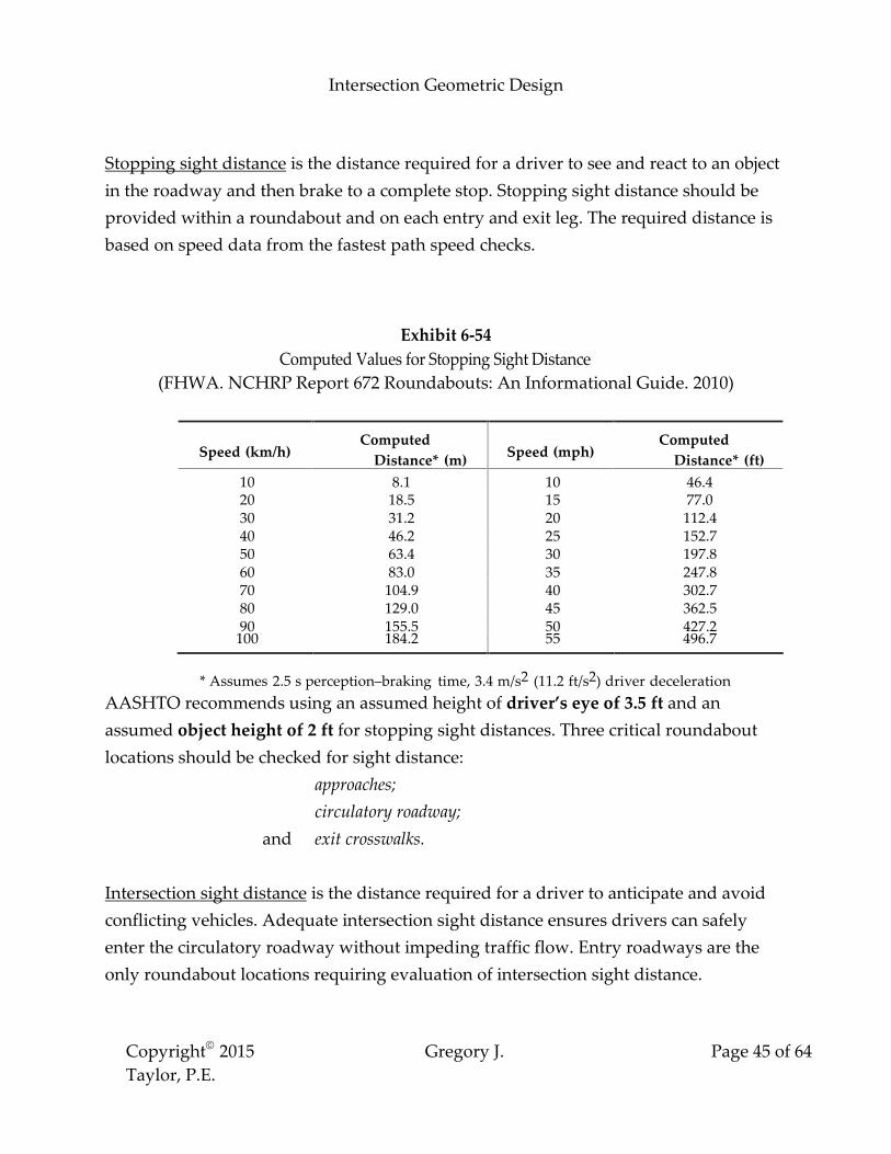
Stopping sight distance is the distance required for a driver to see and react to an object
in the roadway and then brake to a complete stop. Stopping sight distance should be
provided within a roundabout and on each entry and exit leg. The required distance is
based on speed data from the fastest path speed checks.
Exhibit 6-54 Computed Values for Stopping Sight Distance
(FHWA. NCHRP Report 672 Roundabouts: An Informational Guide. 2010)
Speed (km/h)
Computed Distance* (m)
Speed (mph)
Computed Distance* (ft)
10 8.1 10 46.4 20 18.5 15 77.0 30 31.2 20 112.4 40 46.2 25 152.7 50 63.4 30 197.8 60 83.0 35 247.8 70 104.9 40 302.7 80 129.0 45 362.5 90 155.5 50 427.2
100 184.2 55 496.7
* Assumes 2.5 s perception�braking time, 3.4 m/s2 (11.2 ft/s2) driver deceleration
AASHTO recommends using an assumed height of driver�s eye of 3.5 ft and an
assumed object height of 2 ft for stopping sight distances. Three critical roundabout
locations should be checked for sight distance:
approaches;
circulatory roadway;
and exit crosswalks.
Intersection sight distance is the distance required for a driver to anticipate and avoid
conflicting vehicles. Adequate intersection sight distance ensures drivers can safely
enter the circulatory roadway without impeding traffic flow. Entry roadways are the
only roundabout locations requiring evaluation of intersection sight distance.

Intersection Geometric Design
Copyright 2015 Gregory J.
Taylor, P.E. Page 46 of 64
Sight triangles are used to measure intersection sight distance. This triangle consists of a
boundary defining a distance away from the intersection on each approach and by a
line connecting those two limits. The distance between the entering vehicle and the
circulatory roadway is fixed while the other legs of the sight triangle are based on two
conflicting approaches:
1. Entering stream of vehicles from the immediate upstream entry. The
approximate speed can be calculated using the average values for the entering
and circulating speeds.
2. Circulating stream of vehicles entering the roundabout prior to the
immediate upstream entry. The speed can be approximated from the speed of
left turning vehicles.
In both cases the distance is a function of vehicular speed and a reasonable design value
of the critical headway for the drivers. These sight triangle legs should follow the
curvature of the roadway, and not be measured as straight lines but as distances along
the vehicle path.
In some cases, sight distance at the roundabout may be increased at the expense of the
roundabout�s visibility. Normally, it is desirable to allow no more than the minimum
required intersection sight distance for each approach. Excessive visibility may result in
higher speeds and safety reduction for the roundabout.
The AASHTO �Green Book� recommends that intersection sight distance should be
measured using an assumed height of driver�s eye of 3.5 ft and an assumed object
height of 3.5 ft.
Angles of Visibility
The intersection angle at roundabouts is measured between the vehicular alignment at
the entry and the sight line required. This angle must allow drivers to comfortably turn
their heads to view oncoming traffic upstream. Current guidelines recommend using an
intersection angle of 75˚ to design for older driver and pedestrian needs.
Intersection Geometric Design
Copyright 2015 Gregory J.
Taylor, P.E. Page 47 of 64
Size, Position, and Alignment of Approaches
The design of a roundabout involves optimizing the following design decisions to
balance design principles and objectives:
size
position
and the alignment of the approach legs.
Creating the best design will often be based upon the constraints of the project site
balanced with the ability to control traffic speeds, accommodate over-sized vehicles,
and meet other design criterion.
Normal Capacity
Single-lane circulatory road 1400 to 2400 vehicles/hour
Two-lane circulatory road 2200 to 4000 vehicles/hour
Maximum Capacity
Single-lane entry 1300 vehicles/hour
Two-lane entry 1800 vehicles/hour
Inscribed Circle Diameter
The inscribed circle is the entire area within a roundabout between all approaches and
exits. Its diameter consists of the distance across the central island (including the truck
apron) bordered by the outer curb of the circulatory roadway. A number of design
objectives determine the inscribed circle diameter and designers often have to
experiment with varying dimensions before determining the optimal roundabout size.
For single-lane roundabouts, the inscribed circle�s size depends on the design vehicle�s
turning requirements � circulatory roadway width, entry/exit widths, radii and angles.

Intersection Geometric Design
Copyright 2015 Gregory J.
Taylor, P.E. Page 48 of 64
For multilane roundabouts, the size is dependent on balancing deflection with aligning
natural vehicle paths. Capacity
A roundabout�s capacity and size depends on the number of lanes required to handle
future traffic. Exhibit 3-12 illustrates a simple, conservative way to estimate roundabout
lane requirements. It is applicable for the following conditions:
Ratio of peak-hour to daily traffic (K) 0.09 to 0.10
Acceptable volume-to-capacity ratio 0.85 to 1.00
Ratio of minor street to total entering traffic 0.33 to 0.50
Direction distribution of traffic (D) 0.52 to 0.58 Alignment of Approaches
The entry alignment of the approaching legs to a roundabout affects the deflection and
speed control achieved, accommodation for the design vehicle, sight angles to drivers,
and property impacts/costs.
Although it is desirable for these alignments of the roundabout approaches to pass
through the center of the inscribed circle, it is not mandatory for a successful design.
SINGLE-LANE ROUNDABOUTS Single-lane roundabout design consists of single-lane approaches at all legs and a
single-lane circulatory roadway around a central island. This design permits slightly
higher operation speeds for the entry, exit and the circulatory roadway. Like all
roundabouts, the size of single-lane design is largely dependent on the type of design
vehicle and available right-of-way.
Single-lane Geometric Design Characteristics
Intersection Geometric Design
Copyright 2015 Gregory J.
Taylor, P.E. Page 49 of 64
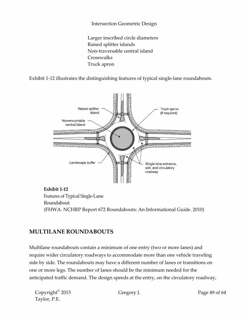
Larger inscribed circle diameters Raised splitter islands Non-traversable central island Crosswalks Truck apron
Exhibit 1-12 illustrates the distinguishing features of typical single-lane roundabouts.
Exhibit 1-12 Features of Typical Single-Lane Roundabout (FHWA. NCHRP Report 672 Roundabouts: An Informational Guide. 2010)
MULTILANE ROUNDABOUTS Multilane roundabouts contain a minimum of one entry (two or more lanes) and
require wider circulatory roadways to accommodate more than one vehicle traveling
side by side. The roundabouts may have a different number of lanes or transitions on
one or more legs. The number of lanes should be the minimum needed for the
anticipated traffic demand. The design speeds at the entry, on the circulatory roadway,
Intersection Geometric Design
Copyright 2015 Gregory J.
Taylor, P.E. Page 50 of 64
and at the exit may be slightly higher than those for single-lane roundabouts. Multilane
roundabouts include raised splitter islands, truck aprons, a non-traversable central
island, and appropriate entry path deflection.
The size of a multilane roundabout is typically determined by balancing two critical
design objectives:
the need to achieve deflection;
and providing sufficient natural vehicle path alignment.
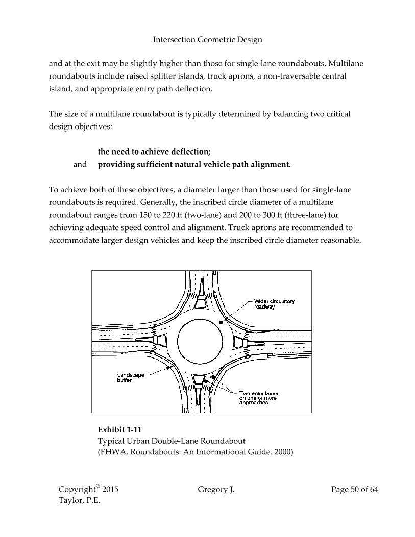
To achieve both of these objectives, a diameter larger than those used for single-lane
roundabouts is required. Generally, the inscribed circle diameter of a multilane
roundabout ranges from 150 to 220 ft (two-lane) and 200 to 300 ft (three-lane) for
achieving adequate speed control and alignment. Truck aprons are recommended to
accommodate larger design vehicles and keep the inscribed circle diameter reasonable.
Exhibit 1-11 Typical Urban Double-Lane Roundabout (FHWA. Roundabouts: An Informational Guide. 2000)

Intersection Geometric Design
Copyright 2015 Gregory J.
Taylor, P.E. Page 51 of 64
MINI-ROUNDABOUTS Mini-roundabouts are small intersection designs with a fully traversable central island
that are commonly used in low-speed urban environments (average operating speeds of
30 mph or less). The small footprint of a mini-roundabout (inscribed circle diameter less
than 90 ft) can be useful in such environments where conventional roundabout design
is limited by right-of-way constraints. The small diameter is made possible by using a
fully traversable central island for accommodating heavy vehicles. Passenger cars
should be able to exit the mini-roundabout without running over the central island. The
overall design should naturally guide entering vehicles along their intended path and
minimize traversing the central island.
Mini-roundabouts are very popular for retrofit applications due to their low cost from
requiring minimal additional pavement at the intersecting roads and minor widening at
the corner curbs. Small, mini-roundabouts are also seen as pedestrian-friendly with
short crossing distances and very low vehicle entry/exit speeds.
Limitations of mini-roundabouts are due to the reduced ability to control speeds with
the traversable central island. Therefore, it is important to consider the advantages and
limitations of mini-roundabouts versus the larger-diameter roundabouts and
intersection designs based upon site-specific conditions.
Figure 1 (Mini-Roundabouts Technical Summary) shows the distinctive features for a
typical mini-roundabout.

Intersection Geometric Design
Copyright 2015 Gregory J.
Taylor, P.E. Page 52 of 64
Figure 1. Design Features of a Mini-Roundabout (FHWA. Mini-Roundabouts Technical Summary. 2010)
FRONTAGE ROADS Frontage roads preserve the character of the highway and prevent impacts of road
development. These roads are used most frequently on freeways to distribute and
collect roadway traffic between local streets and freeway interchanges. Frontage roads
are typically used adjacent to arterials/freeways where property owners are denied
direct access.

Intersection Geometric Design
Copyright 2015 Gregory J.
Taylor, P.E. Page 53 of 64
A minimum spacing of 150 feet between arterial and frontage roads is recommended in
urban areas to lengthen the spacing between successive intersections along the
crossroads.
This dimension is based on the following criteria:
Shortest acceptable length needed for signs and traffic control devices
Acceptable storage space on crossroad in advance of main intersection
Enables turning movements from the main road onto frontage road
Facilitates U-turns between main lanes and two-way frontage roads
Alleviates potential wrong-way entry onto highway
Frontage roads are typically parallel to the freeway
Either one or both sides
Continuous or non-continuous
Arterial and frontage road connections are a crucial element of design. For slow-moving
traffic and one-way frontage roads, simple openings may be adequate. On high-speed
roadways, ramps should be designed for speed changes and storage.
Frontage road design is also impacted by its intended type of service � it can assume the
character of a major route or a local street.

Intersection Geometric Design
Copyright 2015 Gregory J.
Taylor, P.E. Page 54 of 64
Outer Separations
The �outer separation� is the buffer area between through traffic on a roadway and
local traffic on a frontage road. The wider the separation → the lesser the influence on
through traffic. Wide separations are particularly advantageous at intersections with
cross streets to minimize vehicular and pedestrian conflicts. Separations of 300 feet
allow for minimal vehicle storage and overlapping left-turn lanes.
The cross-section of an outer separation is dependent on:
width
type of arterial
frontage road type
Intersection Geometric Design
Copyright 2015 Gregory J.
Taylor, P.E. Page 55 of 64
The AASHTO �Green Book� provides further information for these types of
separations.
PEDESTRIAN FACILITIES
Sidewalks
The safe and efficient accommodation of pedestrians along the traveled way is equally
important as the provisions for vehicles. By separating pedestrians and vehicles,
sidewalks increase pedestrian safety and help vehicular capacity. Sidewalks are
typically an integral part of the transportation system in central business districts.
Data suggests that providing sidewalks along highways in rural and suburban areas
results in a reduction in pedestrian accidents.
Early consideration of pedestrian needs during the project development process may
also streamline compliance with accessibility requirements of the Americans with
Disabilities Act Accessibility Guidelines (ADAAG). Intersections designed with proper
curb ramps, sidewalks, pedestrian signals, and refuge islands can also aid in
furnishing a pedestrian-friendly environment.
Sidewalks are typically placed along roadways without shoulders � even at locations
with light pedestrian traffic. For sidewalk locations along high-speed roads, buffer
areas may be utilized to distance the sidewalk from the traveled way.
Sidewalks should be wide enough for the volume and type of expected pedestrian
traffic. Typical residential sidewalks vary in width from 4 to 8 feet. The Americans with
Disabilities Act Accessibility Guidelines (ADAAG) require passing sections for sidewalks
with widths less than 5 feet spaced every 200 feet. An optional planted strip may be
provided between the sidewalk and the curb (2 ft minimum width) to allow for
maintenance activities. At locations with sidewalks adjacent to the curb, the width
should be 2 feet wider than the minimum width required.

Intersection Geometric Design
Copyright 2015 Gregory J.
Taylor, P.E. Page 56 of 64
Advantages of Buffer Areas
Increased pedestrian distance from moving
Aesthetics of the facility
Reduced width of hard surface space
Space for snow storage
A major disadvantage of buffers or plant strips is the possibility of requiring additional
right-of-way.
The wider the sidewalk, the more room there is for street furniture, trees, utilities, and
pedestrians plus it is easier to maneuver around these fixed objects. It is important not
to overlook the need to maintain as unobstructed a pathway as possible. Grade-Separated Pedestrian Crossings
A grade-separated pedestrian facility (either over or under the roadway) permits
pedestrian and vehicle crossings at different levels without interference. These
structures may be used at locations where pedestrian/traffic volumes, intersection
capacity, etc. encourage their construction. Governmental regulations and codes can
provide additional design guidance when considering these facilities. The AASHTO
Guide for the Planning, Design, and Operation of Pedestrian Facilities provides more specific
information for these structures.
Pedestrian walkways should be a minimum of 8 feet wide. Wider walkways may be
used for tunnels, high pedestrian traffic areas, and overpasses with a tunnel effect (from
screens).
Vandalism is a legitimate concern for pedestrian/vehicle overpass structures � where
individuals drop objects onto oncoming traffic. While there is no universal deterrent,
options have been developed to deal with this problem, including:
solid plastic enclosures
screens

Intersection Geometric Design
Copyright 2015 Gregory J.
Taylor, P.E. Page 57 of 64
Possible Overpass Locations (with screens)
Schools, playgrounds, etc. � where children may be unaccompanied
Large urban pedestrian overpasses � not under police surveillance
Where history indicates a need
Curb Ramps
Curb ramps provide access between sidewalks and streets at pedestrian crossings. Basic
curve types have been developed for use according to intersection geometric
characteristics.
Curb Ramp Design Considerations
o Sidewalk width
o Sidewalk location
o Curb height & width
o Turning radius & curve length
o Street intersection angle
o Sign & signal locations
o Drainage inlets
o Utilities
o Sight obstructions
o Street width

Intersection Geometric Design
Copyright 2015 Gregory J.
Taylor, P.E. Page 58 of 64
o Border width
The Public Rights-of-Way Accessibility Guidelines provide the following guidance for curb
ramps:
Minimum curb ramp width 4 feet
Maximum curb ramp grade 8.33%
Sidewalk cross slopes 2% maximum
Top level landing area 4 ft x 4 ft
(with no obstructions, 2% maximum cross slope)
Curb ramp locations should be closely integrated with the pedestrian crosswalk by
having the curb ramp bottom within the crosswalk�s parallel boundaries, and
perpendicular to the curb face. These ramps are typically placed within the corner
radius or beyond the radius on the tangent section.

Intersection Geometric Design
Copyright 2015 Gregory J.
Taylor, P.E. Page 59 of 64

Intersection Geometric Design
Copyright 2015 Gregory J.
Taylor, P.E. Page 60 of 64
BICYCLE FACILITIES
Due to the bicycle�s popularity as a mode of transportation, their needs should be
considered when designing roadways. The main factors to consider for accommodating
bicycles include:
Type of bicyclist being served by the route (experienced, novice, children)
Type of roadway project (widening, new construction, resurfacing)
Traffic operations & design characteristics (traffic volume, sight distance,
development) The basic types of bicycle facilities include:
Shared lane: typical travel lane shared by both bicycles and vehicles
Wide outside lane: outside travel lane (14 ft minimum) for both bicycles &
vehicles
Bicycle lane: part of roadway exclusively designated (striping or signing) for
bicycles, etc.
Shoulder: roadway paving to the right of traveled way for usage
Multiuse path: physically separated facility for bicycles, etc.
Transportation planners and designers list these factors that have a great impact on
bicycle lanes � traffic volume, average operating speed, traffic mix, on-street parking, sight
distance, and number of intersections.
RAILROAD-HIGHWAY GRADE CROSSINGS
The geometric roadway design for a railroad crossing should draw motorists� attention
to roadway conditions. The major consideration is to enable highway traffic to move
more efficiently.
Horizontal Alignment Guidelines

Intersection Geometric Design
Copyright 2015 Gregory J.
Taylor, P.E. Page 61 of 64
Intersect tracks at right angles and avoid nearby intersections or ramps
Enhances sight distance
Reduces conflicting vehicle movements
Preferable for cyclists
Avoid locating crossings on highway or railroad curves
Curvature inhibits driver�s perception and sight distance
Causes poor rideability and maintenance challenges (superelevation)
Where possible, the vertical alignment for a railroad-highway crossing should be as
level as practical to enhance rideability, sight distance, acceleration, and braking.
Limitations for the roadway surface include:
Being on the same plane as the rail tops for a minimum of 2 feet outside the rails
Limited to 3 inches higher or lower than the top of the nearest rail at 30 feet from the
rail
Grade crossing geometric design consists of utilizing alignments (horizontal and
vertical), sight distance, and cross-sections. This design may change with the type of
warning devices used.
Railroad-highway grade crossing traffic control devices may consist of passive warning
devices (signs, pavement markings) and/or active warning devices (flashing light
signals, automatic gates). Guidelines regarding these devices are covered fully in the
MUTCD.
At railroad-highway grade crossings without train-activated warning devices, the
following two scenarios are typically used to determine sight distances:
Vehicle can see the approaching train with a sight line adequate to pass the crossing prior
to the train�s arrival (GO)
Vehicle can see the approaching train with a sight line adequate to stop prior to crossing
(STOP)
Intersection Geometric Design
Copyright 2015 Gregory J.
Taylor, P.E. Page 62 of 64
The following texts provide a complete discussion of railroad-highway grade crossing
sight distances:
NCHRP Report 288
Railroad-Highway Grade Crossing Surfaces
SUMMARY OF INTERSECTION DESIGN
This course summarized and highlighted the basic elements of at-grade intersection
design. There are clearly many considerations, including costs, maintenance, adjacent
land uses, operational and safety impacts, environmental impacts, and infrastructure
needs. The designer�s task requires balancing trade-offs in order to provide safe,
efficient, and cost-effective transportation of people and goods.
Intersections are similar to other major infrastructure projects by consuming valuable
resources and often adversely affecting the users or those in close proximity to them.
All parties charged with resource protection normally expect any adverse effects to be
addressed in the planning and design of highways.
The mere application of design standards and criteria to �solve� a problem is
inadequate. The various complex safety and operational relationships behind the design
guidelines and criteria must be clearly understood. Designers must be prepared to
present the reasons for a design, and be prepared to develop any alternatives. This is

Intersection Geometric Design
Copyright 2015 Gregory J.
Taylor, P.E. Page 63 of 64
possible only if the designer understands how all elements of the roadway (horizontal
and vertical alignment, cross section, intersections, and interchanges) contribute to its
safety and operation.
REFERENCES
A Policy on Geometric Design of Highways and Streets, 6th Edition
AASHTO. Washington, D.C. 2011.
Note: All figures, illustrations, tables, etc. contained within this course are from
this text unless noted otherwise.
Handbook of Simplified Practice for Traffic Studies
Center for Transportation Research & Education � Iowa State University.
Ames, Iowa. 2002.
Mini-Roundabouts Technical Summary
FHWA. Washington, D.C. 2010.
Intersection Geometric Design
Copyright 2015 Gregory J.
Taylor, P.E. Page 64 of 64
NCHRP Report 672 Roundabouts: An Informational Guide, 2nd Edition
FHWA. Washington, D.C. 2010.
Roundabouts: An Informational Guide
FHWA. Washington, D.C. 2000.
Standard Roadway Drawings
Tennessee Department of Transportation.
Traffic Engineering Handbook, 5th Edition
Institute of Transportation Engineers. Washington, D.C. 1999.

QUIZ Intersection Geometric Design
Gregory J. Taylor, P.E.
1. Avoid grades for intersecting roads in excess of _________ percent within intersection
areas.
a. 2
b. 3
c. 4
d. 5
2. A WB-62 design vehicle is classified as a ______________________________.
a. Turnpike double combination
b. Triple semitrailer
c. Intermediate semitrailer combination
d. Interstate semitrailer
3. The L₄ component for deceleration lanes is defined as
_____________________________.
a. Storage length
b. Distance traveled (complete deceleration to a stop)
c. Taper distance
d. Distance traveled during perception-reaction time
4. The two main types of offset left-turn lane configurations are perpendicular and
tapered.
a. True
b. False
5. Maximum entering design speeds of _____________________ mph are recommended
for single-lane roundabouts.
a. 10 to 15
b. 20 to 25
c. 30 to 35
d. 40 to 45

QUIZ Intersection Geometric Design
Gregory J. Taylor, P.E.
Copyright 2015 Gregory J. Taylor, P.E. Page 2 of 5
6. Roadway surfaces at railroad crossings should be limited to ________________ higher
or lower than the top of the nearest rail.
a. 1 inch
b. 2 inches
c. 3 inches
d. 4 inches
7. ________________________________________ are the preferable type of skewed
median end.
a. Semicircular
b. Parallel bullet nose
c. Circular
d. Asymmetrical bullet nose
8. Object height is based on a vehicle height of 3.50 feet.
a. True
b. False
9. Angles of intersection for three-leg intersections typically range from
_____________________ degrees.
a. 30 to 90
b. 60 to 120
c. 90 to 150
d. 120 to 180
10. All of the following are primary functions of islands except:
a. Location
b. Refuge
c. Division
d. Channelization
11. The preferable minimum curbed corner island area is __________________________.

QUIZ Intersection Geometric Design
Gregory J. Taylor, P.E.
Copyright 2015 Gregory J. Taylor, P.E. Page 3 of 5
a. 25 ft²
b. 50 ft²
c. 75 ft²
d. 100 ft²
12. In most cases, ______________________________________ is the largest design
vehicle for urban collectors/arterials.
a. City Transit Bus (CITY-BUS)
b. Single-Unit Truck (SU)
c. Intermediate Semi-trailer (WB-50)
d. Interstate Semi-trailer (WB-65 or 67)
13. What is the computed stopping sight distance for 40 mph?
a. 247.8 feet
b. 302.7 feet
c. 362.5 feet
d. 427.2 feet
14. The cross-section of an outer separation is dependent on all of the following except:
a. Width
b. Type of arterial
c. Frontage road type
d. Design speed
15. The Public Rights-of-Way Accessibility Guidelines recommends a minimum curb
ramp width of _____________________.
a. 3 feet
b. 4 feet
c. 5 feet
d. 6 feet

QUIZ Intersection Geometric Design
Gregory J. Taylor, P.E.
Copyright 2015 Gregory J. Taylor, P.E. Page 4 of 5
16. Sight triangles are areas along intersection approach legs that should be clear of
obstructions that could block a driver�s view.
a. True
b. False
17. Which text was used in this course for fundamental geometric design principles?
a. Traffic Engineering Handbook
b. Manual on Uniform Traffic Control Devices (MUTCD)
c. Roadside Design Guide
d. A Policy on Geometric Design of Highways and Streets (Green Book)
18. The maximum hourly rate at which vehicles can reasonably be expected to pass
through an intersection under prevailing traffic, roadway, and signalization conditions
is the definition of _____________________________.
a. Level of service
b. Capacity
c. Demand
d. Access management
19. Which of the following is not a basic type of intersection?
a. Multi-leg
b. Cul-de-sac
c. Three-leg (T)
d. Four-leg
20. The desirable median width for intersections with two median lanes is
__________________ minimum.
a. 20 feet
b. 24 feet
c. 26 feet
d. 28 feet

QUIZ Intersection Geometric Design
Gregory J. Taylor, P.E.
Copyright 2015 Gregory J. Taylor, P.E. Page 5 of 5
21. One-way roadways used in different quadrants of intersections to separate left-
turning vehicles from through traffic by forcing all turns to be made from the right side
are called ______________________.
a. Jughandles
b. Continuous-Flow Intersections
c. Roundabouts
d. Crossover-Displaced Left-Turn Intersections
22. Intersection sight distance is the distance required for a driver to anticipate and
avoid conflicting vehicles.
a. True
b. False
23. Bus stop locations are a design control for ____________________________.
a. Roundabouts
b. Parallel tapers
c. Jughandles
d. Channelized intersections
24. The maximum capacity for a single-lane roundabout entry is ____________________
vehicles per hour.
a. 1000
b. 1300
c. 1800
d. 2200
25. The main objective of intersection design is to facilitate the roadway user and
enhance efficient vehicle movement.
a. True
b. False