Embed Size (px)
Citation preview

Intersections from the Inside Out: A Different Workflow for AutoCAD® Civil 3D® Steve Boon – McElhanney Consulting Services Ltd.
CI2160 The design of roadways is typically based on the development of an alignment, then a profile, and finally a typical section. Many users who design intersections, ramps, or widenings run into difficulties because the process in AutoCAD Civil 3D software assumes that the road edge profile is designed semi-independently of the centerlines. In this class, you will learn a technique which allows the use of the classic alignment–profile–section process to design a widening, a ramp, or the turning lanes of an intersection. This technique can be used for all types of corridors where the pavement edge elevations are to be controlled by a specified crossfall from another profile or surface.
Learning Objectives At the end of this class, you will be able to:
• Use superelevation parameters to aid in the design of curb returns.
• Build assemblies which allow the user to match a lane widening to an existing surface and crossfall.
• Build assemblies for the design of ramps which transition from another lane edge through a gore to an independent lane.
• Put all of the pieces together in a corridor model.
About the Speaker Steve has been an AutoCAD user since 1994 and was an early adopter of Civil 3d.
After graduating from the British Columbia Institute of Technology, Steve has been employed for the past 18 years in a variety of roles in the consulting engineer industry. He has been a survey assistant, party chief, drafter, designer and project manager. At McElhanney Consulting he provides training and technical support to other CADD users, develops standards and workflows, and spends time looking for ways to get the most out of the software.
While waiting for corridor rebuilds Steve is also an active participant on the Civil3d discussion group, answering the questions of other users. He is an Autodesk Certified Professional and a member of AUGI.
Intersections from the Inside Out: A Different Workflow for AutoCAD® Civil 3D®
2
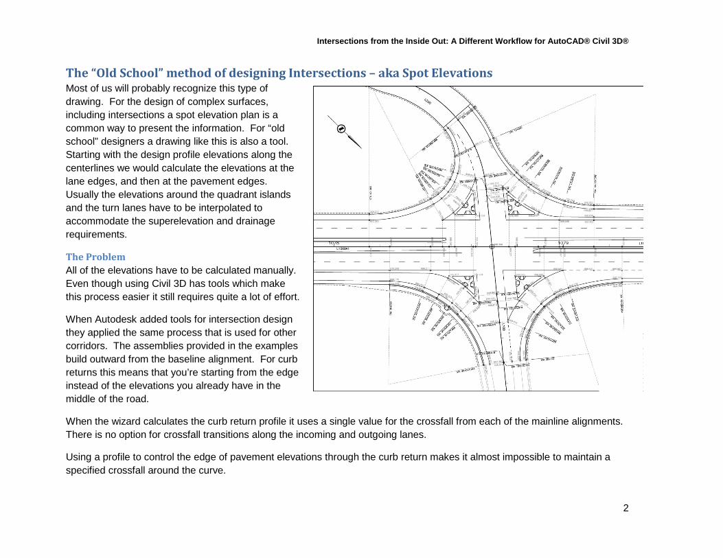
The “Old School” method of designing Intersections – aka Spot Elevations Most of us will probably recognize this type of drawing. For the design of complex surfaces, including intersections a spot elevation plan is a common way to present the information. For “old school” designers a drawing like this is also a tool. Starting with the design profile elevations along the centerlines we would calculate the elevations at the lane edges, and then at the pavement edges. Usually the elevations around the quadrant islands and the turn lanes have to be interpolated to accommodate the superelevation and drainage requirements.
The Problem All of the elevations have to be calculated manually. Even though using Civil 3D has tools which make this process easier it still requires quite a lot of effort.
When Autodesk added tools for intersection design they applied the same process that is used for other corridors. The assemblies provided in the examples build outward from the baseline alignment. For curb returns this means that you’re starting from the edge instead of the elevations you already have in the middle of the road.
When the wizard calculates the curb return profile it uses a single value for the crossfall from each of the mainline alignments. There is no option for crossfall transitions along the incoming and outgoing lanes.
Using a profile to control the edge of pavement elevations through the curb return makes it almost impossible to maintain a specified crossfall around the curve.
Intersections from the Inside Out: A Different Workflow for AutoCAD® Civil 3D®
3
A Simple Intersection
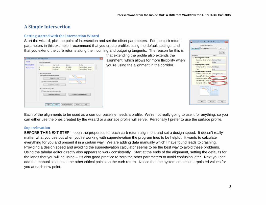
Getting started with the Intersection Wizard Start the wizard, pick the point of intersection and set the offset parameters. For the curb return parameters in this example I recommend that you create profiles using the default settings, and that you extend the curb returns along the incoming and outgoing tangents. The reason for this is
that extending the profile also extends the alignment, which allows for more flexibility when you’re using the alignment in the corridor.
Each of the alignments to be used as a corridor baseline needs a profile. We’re not really going to use it for anything, so you can either use the ones created by the wizard or a surface profile will serve. Personally I prefer to use the surface profile.
Superelevation BEFORE THE NEXT STEP – open the properties for each curb return alignment and set a design speed. It doesn’t really matter what you use but when you’re working with superelevation the program tries to be helpful. It wants to calculate everything for you and present it in a certain way. We are adding data manually which I have found leads to crashing. Providing a design speed and avoiding the superelevation calculator seems to be the best way to avoid these problems. Using the tabular editor directly also appears to work consistently. Start at the ends of the alignment, setting the defaults for the lanes that you will be using – it’s also good practice to zero the other parameters to avoid confusion later. Next you can add the manual stations at the other critical points on the curb return. Notice that the system creates interpolated values for you at each new point.
Intersections from the Inside Out: A Different Workflow for AutoCAD® Civil 3D®
4
Viewing and checking the supers There are a couple of options for this. Alignment geometry labels at superelevation critical points are a simple check that the critical values are being applied at the correct station. Superelevation bands are also useful and provide a way to edit graphically.
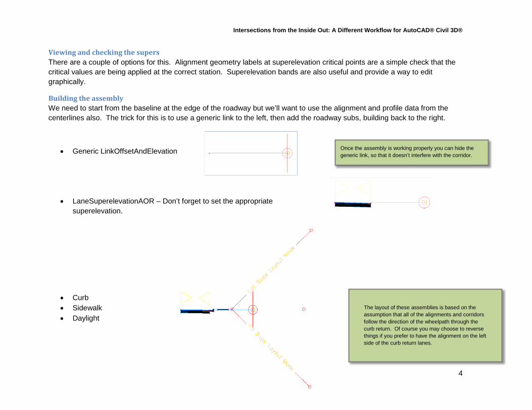
Building the assembly We need to start from the baseline at the edge of the roadway but we’ll want to use the alignment and profile data from the centerlines also. The trick for this is to use a generic link to the left, then add the roadway subs, building back to the right.
• Generic LinkOffsetAndElevation
• LaneSuperelevationAOR – Don’t forget to set the appropriate superelevation.
• Curb • Sidewalk • Daylight
The layout of these assemblies is based on the assumption that all of the alignments and corridors follow the direction of the wheelpath through the curb return. Of course you may choose to reverse things if you prefer to have the alignment on the left side of the curb return lanes.
Once the assembly is working properly you can hide the generic link, so that it doesn’t interfere with the corridor.

Intersections from the Inside Out: A Different Workflow for AutoCAD® Civil 3D®
5
Adding the curb returns to the corridor Use the ribbon tools to add a curb return alignment as a baseline, then add a region. For the target parameters:
• The generic link targets the two centerline alignments both horizontally and vertically. • The lane width targets back to the curb return alignment for width only.
When you’re ready to tie the curb return regions to the main road it’s often useful to add a top surface with a fairly tight contour interval to confirm that the elevations from different regions match up cleanly.
Pitfalls Make sure that the region frequencies are similar or you may have problems with the surface triangulation from one baseline to the other. Watch out for profiles that don’t match elevation or grade from one part of the corridor to another.

Intersections from the Inside Out: A Different Workflow for AutoCAD® Civil 3D®
6
A Complex Intersection
The Issues This was an existing intersection which required upgrading to accommodate a new industrial development to the south. There are several issues which complicated this project. The highway alignment is a high-speed curve with poor sightlines from the west, requiring long acceleration & deceleration lanes to allow vehicles to use the intersection. The existing superelevation of the highway makes it difficult for the ramps to transition to and from the side road. The logging trucks which will use the intersection often have long loads which require extra space while turning to avoid conflicts with other traffic. There is an existing gas station and corner store in the southeast quadrant which is to remain, but we need to replace the existing access by improving the service road and its intersection. To the southwest are other businesses and residences on a hill.
L100 - Highway
L30 – Service Road
Intersections from the Inside Out: A Different Workflow for AutoCAD® Civil 3D®
7
All of the 2d linework in the Design Base 4 – 1 drawing has already been drawn to suit the design standards of the Ministry of Transport, and the City. The geometry of the intersections has been checked with turn simulation software to confirm that fuel trucks can get in and out of the gas station, and other trucks can access the industrial development.
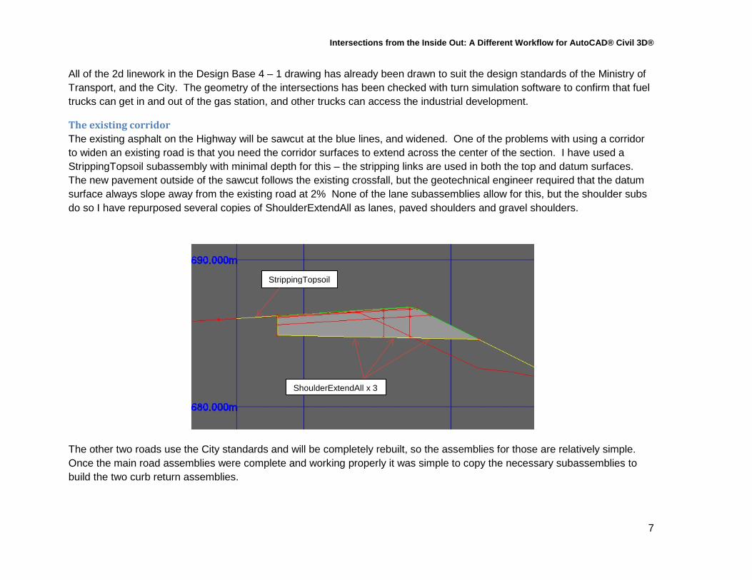
The existing corridor The existing asphalt on the Highway will be sawcut at the blue lines, and widened. One of the problems with using a corridor to widen an existing road is that you need the corridor surfaces to extend across the center of the section. I have used a StrippingTopsoil subassembly with minimal depth for this – the stripping links are used in both the top and datum surfaces. The new pavement outside of the sawcut follows the existing crossfall, but the geotechnical engineer required that the datum surface always slope away from the existing road at 2% None of the lane subassemblies allow for this, but the shoulder subs do so I have repurposed several copies of ShoulderExtendAll as lanes, paved shoulders and gravel shoulders.
The other two roads use the City standards and will be completely rebuilt, so the assemblies for those are relatively simple. Once the main road assemblies were complete and working properly it was simple to copy the necessary subassemblies to build the two curb return assemblies.
StrippingTopsoil
ShoulderExtendAll x 3

Intersections from the Inside Out: A Different Workflow for AutoCAD® Civil 3D®
8
The L30 – L67 intersection This one is similar to the simple intersection from earlier, but there is a complication. The L30 profile doesn’t leave enough room for a transition from the -8% approach grade to a standard 2% crown at the intersection. The solution for this is to use the superelevation parameters for the L67 alignment to lift the left edge of that roadway up to meet the profile of the crossing road.
The L30 profile is 2% across the intersection but the two alignments are not perpendicular. This skew means that the slopes across the L67 lanes have to be something less than 2%
Rather than calculate this I chose to create a region along the full length of L30 and use the Inquiry tool to extract the slope value. I then split this region in two and adjusted the region boundaries to make room for the intersection.

Intersections from the Inside Out: A Different Workflow for AutoCAD® Civil 3D®
9
Once we are satisfied with the corridor region we can extract the featurelines which will be used for targets controlling the curb returns. Make sure that the dynamic link option is turned off, or you won’t be able to use the new featureline as a target. If the design of the main roadways changes later you’ll have to edit these featurelines yourself, either by grip editing or using the Elevations from Surface tool to match the new grades at the lane edge.
Add a new baseline and region at the L31 curb return alignment. The curb return assembly is already built, and we are not setting superelevation parameters in this case so the only other step is to assign the targets and let the corridor rebuild.
Open the drawing Design Base 4 - 2. At this point the four curb returns are complete. Note how the taper development for the other intersection means that none of the edges are straight or parallel to each other. The method used here allows for this, with flexibility and control options that would not have been possible using the Intersection wizard.
Intersections from the Inside Out: A Different Workflow for AutoCAD® Civil 3D®
10
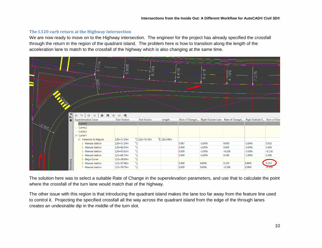
The L120 curb return at the Highway intersection We are now ready to move on to the Highway intersection. The engineer for the project has already specified the crossfall through the return in the region of the quadrant island. The problem here is how to transition along the length of the acceleration lane to match to the crossfall of the highway which is also changing at the same time.
The solution here was to select a suitable Rate of Change in the superelevation parameters, and use that to calculate the point where the crossfall of the turn lane would match that of the highway.
The other issue with this region is that introducing the quadrant island makes the lane too far away from the feature line used to control it. Projecting the specified crossfall all the way across the quadrant island from the edge of the through lanes creates an undesirable dip in the middle of the turn slot.
Intersections from the Inside Out: A Different Workflow for AutoCAD® Civil 3D®
11
There are several solutions for this problem. In this case we can create an offset alignment from L120. Next we cut a profile from the current top surface of the corridor and use that as a basis for building a layout profile. The new alignment and profile can then be added to the region as targets, and the corridor is allowed to rebuild.
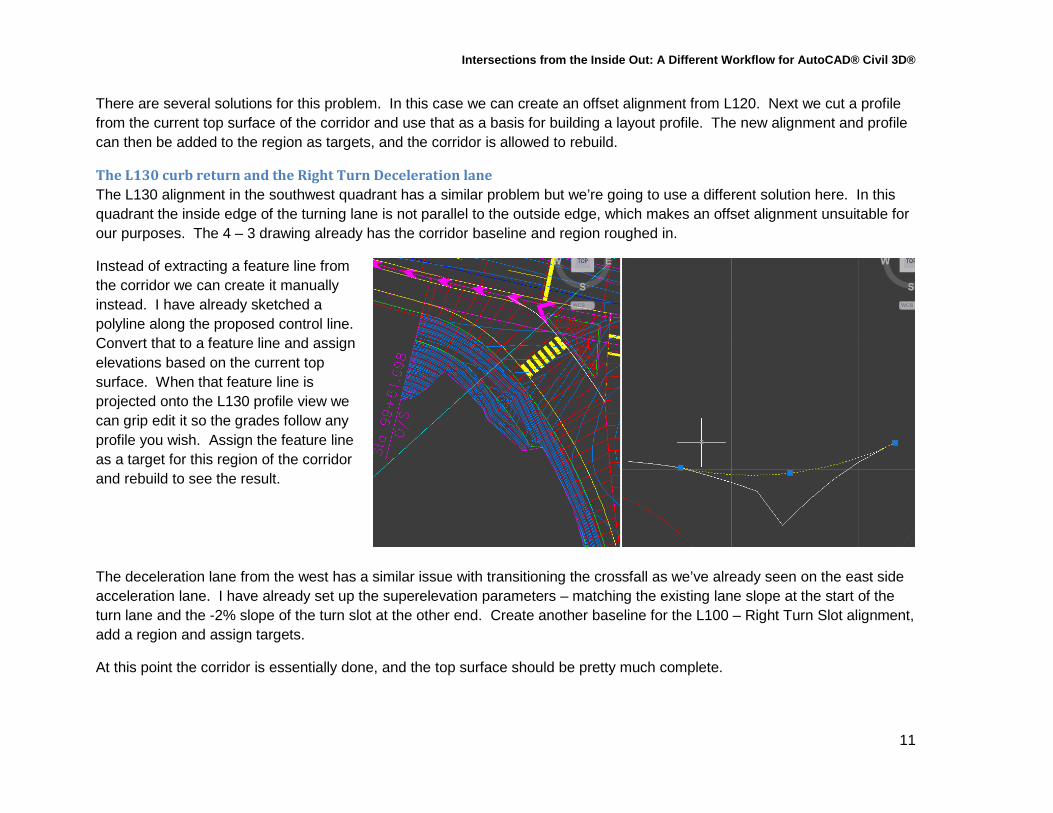
The L130 curb return and the Right Turn Deceleration lane The L130 alignment in the southwest quadrant has a similar problem but we’re going to use a different solution here. In this quadrant the inside edge of the turning lane is not parallel to the outside edge, which makes an offset alignment unsuitable for our purposes. The 4 – 3 drawing already has the corridor baseline and region roughed in.
Instead of extracting a feature line from the corridor we can create it manually instead. I have already sketched a polyline along the proposed control line. Convert that to a feature line and assign elevations based on the current top surface. When that feature line is projected onto the L130 profile view we can grip edit it so the grades follow any profile you wish. Assign the feature line as a target for this region of the corridor and rebuild to see the result.
The deceleration lane from the west has a similar issue with transitioning the crossfall as we’ve already seen on the east side acceleration lane. I have already set up the superelevation parameters – matching the existing lane slope at the start of the turn lane and the -2% slope of the turn slot at the other end. Create another baseline for the L100 – Right Turn Slot alignment, add a region and assign targets.
At this point the corridor is essentially done, and the top surface should be pretty much complete.

Intersections from the Inside Out: A Different Workflow for AutoCAD® Civil 3D®
12
The Hidden problems and the Fixes The corridor may look good from above, but there are some hidden issues underneath. The first is caused by the corridor sections from one baseline not matching to the adjacent baselines. The easiest fix for this situation is to remove all of the automatically generated sections along one of the corridor regions and replace them with manual stations that match the sections from the other baseline. Change the frequency defaults to a large value and then insert sections at the appropriate locations.
The second problem comes from the fact that the top and bottom of the road structure isn’t parallel. The ShoulderExtendAll subassemblies being used here all have the same default thickness at their inside edge. The only way that I’ve been able to fix them is using the corridor view editor. Measure the thickness of the subbase material at the outside edge of each subassembly, and apply that to the inside thickness of the next sub.

Intersections from the Inside Out: A Different Workflow for AutoCAD® Civil 3D®
13
Final Cleanup The last drawing Design Base 5 – 5 shows off the finished product with all of the final design tweaks and drafting edits complete:
• The different material thickness of the City and Highway specifications required edits to taper the subgrade surface correctly at the Highway intersection.
• The different ditch specifications required some parameter editing to taper from one style to the other. • The corridor extents used as surface boundary left small gaps at the ends of the regions unless they were allowed to
touch. I chose to extract the boundary instead, edit it to clean up these areas, and then reapply it as a Boundary from Polygon.
• It was necessary to swap some TIN edges in the Datum surface to clean up issues at the intersections.
Measured distance from the outside of the inner subassembly assigned to the subbase depth of the outer sub.
Intersections from the Inside Out: A Different Workflow for AutoCAD® Civil 3D®
14
Ramps and Gores The Interchange drawings show how the technique can be applied to a ramp and gore without the use of the Intersection wizard. In this case we’re not using the Intersection Wizard at all.
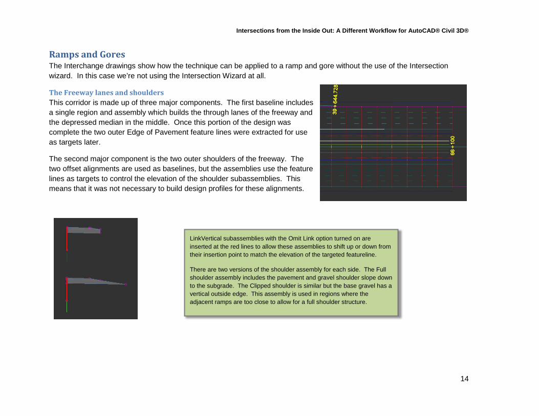
The Freeway lanes and shoulders This corridor is made up of three major components. The first baseline includes a single region and assembly which builds the through lanes of the freeway and the depressed median in the middle. Once this portion of the design was complete the two outer Edge of Pavement feature lines were extracted for use as targets later.
The second major component is the two outer shoulders of the freeway. The two offset alignments are used as baselines, but the assemblies use the feature lines as targets to control the elevation of the shoulder subassemblies. This means that it was not necessary to build design profiles for these alignments.
LinkVertical subassemblies with the Omit Link option turned on are inserted at the red lines to allow these assemblies to shift up or down from their insertion point to match the elevation of the targeted featureline.
There are two versions of the shoulder assembly for each side. The Full shoulder assembly includes the pavement and gravel shoulder slope down to the subgrade. The Clipped shoulder is similar but the base gravel has a vertical outside edge. This assembly is used in regions where the adjacent ramps are too close to allow for a full shoulder structure.

Intersections from the Inside Out: A Different Workflow for AutoCAD® Civil 3D®
15
The Freeway ramps The final major parts of this corridor are the ramps. Each one includes a tangent which forms the taper, and then a transition spiral to a superelevated curve. Each of the ramp baselines has three regions. The ramp gore assembly is essentially the same as the ones used in the previous examples, with a generic link to the left then roadway assemblies to the right. The other two assemblies are used to build the ramp itself.
Region with Clipped Ramp Assembly Region with Gore Assembly
Region with Full Ramp Assembly
Intersections from the Inside Out: A Different Workflow for AutoCAD® Civil 3D®
16
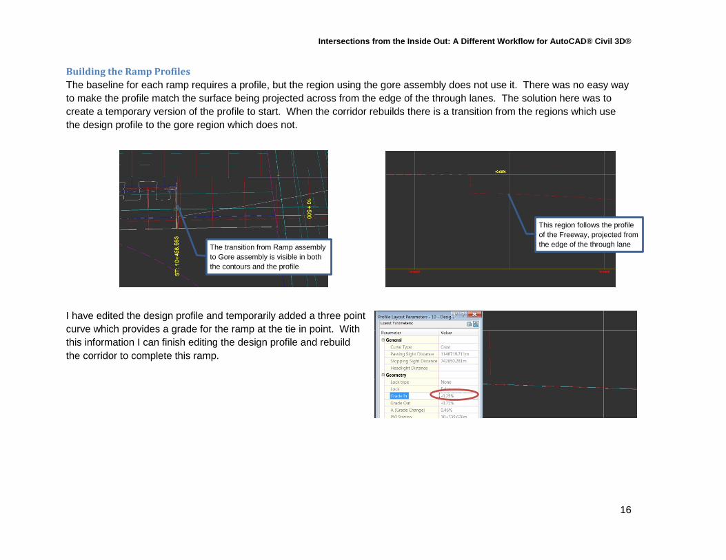
Building the Ramp Profiles The baseline for each ramp requires a profile, but the region using the gore assembly does not use it. There was no easy way to make the profile match the surface being projected across from the edge of the through lanes. The solution here was to create a temporary version of the profile to start. When the corridor rebuilds there is a transition from the regions which use the design profile to the gore region which does not.
I have edited the design profile and temporarily added a three point curve which provides a grade for the ramp at the tie in point. With this information I can finish editing the design profile and rebuild the corridor to complete this ramp.
The transition from Ramp assembly to Gore assembly is visible in both the contours and the profile
This region follows the profile of the Freeway, projected from the edge of the through lane
Intersections from the Inside Out: A Different Workflow for AutoCAD® Civil 3D®
17
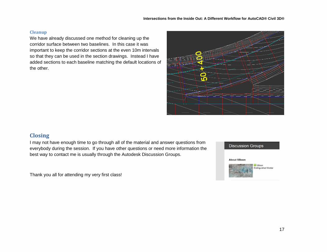
Cleanup We have already discussed one method for cleaning up the corridor surface between two baselines. In this case it was important to keep the corridor sections at the even 10m intervals so that they can be used in the section drawings. Instead I have added sections to each baseline matching the default locations of the other.
Closing I may not have enough time to go through all of the material and answer questions from everybody during the session. If you have other questions or need more information the best way to contact me is usually through the Autodesk Discussion Groups.
Thank you all for attending my very first class!