Embed Size (px)
Citation preview
Interval Data Recorder
Installation & Instruction Manual
One Oxford Valley, Suite 418Langhorne, PA 19047
(800) 334-3666
E-Mon D-MonMetering Products & Systems
®
Test Equipment Depot - 800.517.8431 - 99 Washington Street Melrose, MA 02176
FAX 781.665.0780 - TestEquipmentDepot.com

Index
Chapter 1 Pre-Installation Information
Chapter 2 Mechanical Installation
Chapter 3 Connecting Meters to the IDR Chapter 4 Main Circuit Board Visual Checks
Chapter 5 Optional AC Adapter
Chapter 6 Serial Communications
Appendix A Cable Assembly
Appendix B LED Indicator Locations
Appendix C IDR Circuit Board Components
Appendix D Hardwired System Configuration Diagrams
Appendix E Modem System Configuration Diagrams
Appendix F System Wiring Guides
Test Equipment Depot - 800.517.8431 - 99 Washington Street Melrose, MA 02176
FAX 781.665.0780 - TestEquipmentDepot.com

Chapter 1 Pre-Installation Information
The IDR (Interval Data Recorder) is an energy data collection device. Installation must be performed by qualified personnel only and must be in accordance with local and national electrical codes. E-Mon and its representatives are not responsible for damage or injury from improper installation.
The IDR is contained within a NEMA 12 enclosure and is designed for INDOOR USE ONLY, where ambient temperatures are between +32 and +120 degrees Fahrenheit.
The IDR must be located in an area that is central to the meters connected to it. IMPORTANT: The E-Mon D-Mon® meter that is connected to meter jack #1 on the IDR must be within 100 feet from the IDR, as it supplies low-voltage power to operate the IDR. All other meters can be located up to 500 feet from the IDR.
Note: The IDR with modular jacks is designed to operate with E-Mon D-Mon meters only. Terminal input models can support the monitoring of third-party metering equip-ment; contact E-Mon for further information.
The IDR must be installed in a location according to these guidelines to ensure continued safe, trouble-free operation.
- Do not install near sensitive radio communications equipment or receiving antenna systems.
- Do not install near high-energy electrical fields such as those produced by welding equipment or by high-power electrical motors.
- Always install in an area that is dry, away from any potential liquid or chemical splash hazards. Never install electrical equipment in an area where flammable chemicals or vapors are present.
- The IDR enclosure's door must be kept closed once installed. Exposing the internal circuits to dust, dirt, fumes or high humidity can damage the IDR.
Note: All internal circuits are isolated from the AC line.
Note: IDRs with modular jacks can be powered from either the first E-Mon D-Mon meter or by an external power supply (requires 120VAC). IDRs with removable screw-type connectors require an external power supply (provided).
IDRs are supplied with an ID letter for each group of 8 inputs to make them compatible with the RightEnergyTM software.The available choices are: A-B, C-D, E-F, G-H, I-J, K-L, M-N, O-P, Q-R, S-T, U-V, W-X and Y-Z. No other combinations are available. When mixing 8-point and 16-point IDRs together, it may be necessary to jump up a letter in the system. As an example, if you have 8-point IDRs labelled “A”, “B” and “C”, the 16-point IDR to choose would be the E-F unit.
Test Equipment Depot - 800.517.8431 - 99 Washington Street Melrose, MA 02176
FAX 781.665.0780 - TestEquipmentDepot.com

Chapter 1Pre-Installation Information
The IDR is available in three configurations.
1. Modular Jacks (IDR-8 and IDR-16): Supplied with all modular jacks for use only with the E-Mon D-Mon® meters.
2. Plug-In Screw-Type Connectors (IDR-8 and IDR-16): Supplied with all plug-in screw-type connectors for use with third-party meters (electric, gas, water, etc.) that are provided with a dry contact output pulse.
3. Modular Jacks & Screw-Type Connectors (IDR-16 ONLY): Supplied with 8 modular jacks and 8 screw-type connectors. Used with a mixture of E-Mon D-Mon and third-party meters.
Modular Jacks
Screw-Type ConnectorsModular Jacks
Screw-Type Connectors
TOP
TOP
TOP
Test Equipment Depot - 800.517.8431 - 99 Washington Street Melrose, MA 02176
FAX 781.665.0780 - TestEquipmentDepot.com

Chapter 2Mechanical Installation
********** IMPORTANT **********
THE INTERNAL CIRCUITS OF THE IDR CAN BE DAMAGED BY ELECTRO-STATIC DISCHARGE. BEFORE REACHING INSIDE THE ENCLOSURE, DISCHARGE YOURSELF BY TOUCHING AN EARTH-GROUNDED OBJECT.
ACCIDENTAL DISCHARGE OF STATIC ELECTRICITY ONTO THE CIRCUITBOARD CAN RESULT IN: - LOSS OF STORED DATA - A SYSTEM LOCKUP - PERMANENT DAMAGE TO THE IDR
The IDR is available in two types of enclosure systems:
A. Stand-Alone IDR (Standard Configuration)
The stand-alone configuration consists of one IDR. The enclosure should bemounted using the mounting flanges located at the top and bottom of theenclosure. The enclosure has three available knockouts for cable entrance/exit from the IDR.
NEVER ATTEMPT TO DRILL THROUGH THE STEEL ENCLOSURE. DOINGSO MAY PERMANENTLY DAMAGE THE ELECTRONIC CIRCUITRY ANDWILL VOID ALL WARRANTIES.
B. MMU (Multiple-Meter Unit) Configuration
MMU units containing E-Mon D-Mon® meters and IDRs have been pre-wired bythe factory prior to shipment. The meters have been connected to the IDR.The installer need only make the required communications connections to the IDR and connect the main AC power input for the MMU system. (See Chapter 6 for communications connections.)
Test Equipment Depot - 800.517.8431 - 99 Washington Street Melrose, MA 02176
FAX 781.665.0780 - TestEquipmentDepot.com
Chapter 3Connecting Meters to the IDR
E-Mon D-Mon® Meter Connections
A. Each E-Mon D-Mon meter has two modular jacks located at the top of its main circuit board. The jack on the left (RJ-45, 8-pin), labeled "IDR", is used to connect the meter to the IDR. NEVER USE THE JACK LOCATED ON THE RIGHT SIDE OF THE METER CIRCUIT BOARD TO CONNECT ANY IDR.
B. * Be sure that one E-Mon D-Mon meter is located within 100 feet of the IDR. This meter will be used to supply the low-voltage power necessary to operate the IDR. Connect this meter to jack #1 on the IDR using an 8-conductor flat modular cable. (See Chapter 5 if the IDR has an optional AC adapter.)
C. *All remaining E-Mon D-Mon meters must be connected to meter jacks 2 through 8 using 6-conductor flat modular cable.
D. Option 16 - If the IDR has an option 16 card, connect the meters at jacks 9 through 16 on the option card using 6-conductor flat modular cable.
E. IDR-16s supplied with plug-in screw-type connectors can be up to 500 feet from all meters, and utilize a pair of wires for connecting to the meter pulse output.
* See Appendix C for items B & C above.
** For more information on cable assembly, see Appendix A.
Pulse Output Meters (IDR-16 Only):
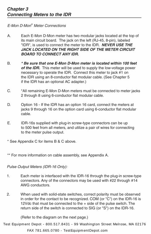
1. Each meter is interfaced with the IDR-16 through the plug-in screw-type connectors. Any of the connectors may be used with #22 through #14 AWG conductors.
2. When used with solid-state switches, correct polarity must be observed in order for the contact to be recognized. COM (or "C") on the IDR-16 is 12Vdc that must be connected to the + side of the pulse switch. The return side of the switch is connected to SIG (or "S") on the IDR-16.
(Refer to the diagram on the next page.)
Test Equipment Depot - 800.517.8431 - 99 Washington Street Melrose, MA 02176
FAX 781.665.0780 - TestEquipmentDepot.com
Chapter 3Connecting Meters to the IDR
2. (Continued)
3. The meters can be up to 500 feet away from the IDR-16.
+
-
COM SIG
Test Equipment Depot - 800.517.8431 - 99 Washington Street Melrose, MA 02176
FAX 781.665.0780 - TestEquipmentDepot.com

Third-Party Meter Connections
In order to connect "third-party" meters such as gas, water or utility-type units,the IDR must be ordered with the "two-screw" terminals instead of the modular jacks that are used with E-Mon D-Mon® meters.
The IDR for third-party metering is always powered by the optional AC adapterpower supply and requires an available 120VAC receptacle to obtain the power.The receptacle must not be switched off at any time. See Chapter 5, OptionalAC Adapter.
The input pulses supplied to the IDR must be non-powered, and they can be either physical (mechanical) contacts or electronic switches. When electronic switches are used, the "COM" terminal on the IDR is the "+" output and the"SIG" is the return from the switch.
The IDR with modular jacks automatically detects when an E-Mon D-Mon meter is connected to it so that it can be recognized by the software when the meters are added or removed. The third-party meter IDR uses a DIP switch toperform this function. This switch is preset at the factory and requires no furtheradjustment.
Chapter 3Connecting Meters to the IDR
TB9 - External Power Input
J23 & J24 - Input PowerSelection
Meter Pulse Input Terminals
Test Equipment Depot - 800.517.8431 - 99 Washington Street Melrose, MA 02176
FAX 781.665.0780 - TestEquipmentDepot.com

Chapter 4Main Circuit Board Visual Checks*
A. Once you have connected meter #1 to jack #1 in the IDR, the IDR should be energized. If the IDR is not energized, verify: 1. Meter 1 is turned on. (Meter 1 powers the IDR; if Meter 1 is not installed and powered up, the IDR will not function.) 2. Verify that JMP8 on the IDR circuit board has a jumper installed. 3. Verify that J23 & J24 on the IDR circuit board are set in the position labeled “MTR”. Both jumpers should be set to the RIGHT position. 4. Verify that the cable between Meter 1 and Jack 1 on the IDR is properly assembled. (See Appendix A for cable assembly.) Note: If the IDR is being powered by the optional AC adapter instead of by Meter 1, see Chapter 5.
B. Verify the status of the LED indicators on the IDR circuit board. (See Appendix B for locations.) 1. Power Supply Indicators - L3, green -> This LED is ON. - L1, green -> This LED is ON. 2. System Status Indicators - D4 (CPU), red -> This LED flashes once per second. If D4 flashes twice per second, the IDR is not initialized. This will be addressed later using the RightEnergyTM software. - D7 (Low Battery) -> This LED must be OFF. This LED indicates a low or missing battery. - D6 (System Error) -> This LED must be OFF. 3. Meter Pulse Indicators - Yellow LEDs P1 through P8 may be flashing. These LEDs indicate each meter's pulse rate. The flash rate depends on how much load the meter is measuring. The faster the pulse, the greater the load. REMEMBER, IF THE METER MEASURES ZERO LOAD, THERE IS NO METER PULSE. WHEN THE PULSE RATE IS ZERO THE YELLOW LED INDICATOR WILL REMAIN EITHER ON OR OFF UNTIL THERE IS A LOAD.
* If one of the LEDs does not flash, verify the meter connection first. If the meter is properly connected, check the meter's display for a flashing load indicator.
Test Equipment Depot - 800.517.8431 - 99 Washington Street Melrose, MA 02176
FAX 781.665.0780 - TestEquipmentDepot.com

B. Status verification of LED indicators (continued)
4. Panel Indicators - Two LEDs are visible through the window on the door of the stand-alone enclosure. THESE LEDS ARE NOT PRESENT IN MMU-STYLE IDRS. - Green LED (Power Indicator) -> The green LED indicates that power is present at the IDR. - Red LED (Tamper Alarm) -> The red LED indicates that the IDR door has been opened. This tamper alarm LED will be on when the door is closed, and will flash when the door is open. When the software startup is performed, the IDR will be initialized by the RightEnergyTM software and the alarm LED will turn off as long as the door remains closed. The alarm can only be reset through the software. 5. Option 16 (applies only if the IDR is equipped with the 16-meter option card) - For each meter (9-16) installed on the options card, another set of yellow LEDs (P9-P16) will be present. These LEDs indicate the meter pulse rate for meters 9 through 16.
Chapter 4Main Circuit Board Visual Checks
Test Equipment Depot - 800.517.8431 - 99 Washington Street Melrose, MA 02176
FAX 781.665.0780 - TestEquipmentDepot.com

Chapter 5Optional AC Adapter (Optional External 120VAC Power Supply)
** If you are NOT using the optional AC adapter to power the IDR, proceedto Chapter 6. **
Instead of powering the IDR using Meter 1, E-Mon can supply an optionalAC adapter. If the IDR was provided with this option, verify the following:
1. Jumpers J23 & J24 on the IDR circuit board are set to the LEFT position (position labeled "EXT"). 2. Jumper at JMP8 MUST be removed. 3. The AC adapter's two-wire cord must be plugged into the IDR at TB9. (The polarity of these wires does not matter.) 4. Plug the AC adapter into a 120VAC outlet.
Note: The AC adapter is designed to be used with a 120VAC outlet only.
5. The IDR should now be energized. Perform the visual checks outlined in Chapter 4.
Note: The AC adapter provides an isolated 18VAC/300mA power sourcefor the IDR. Contact E-Mon at (800) 334-3666 if another power supply is to be used.
Test Equipment Depot - 800.517.8431 - 99 Washington Street Melrose, MA 02176
FAX 781.665.0780 - TestEquipmentDepot.com

A. Hardwired System using the RS-232 Communications Key (See the hardwired system configuration diagrams in Appendix F.)
The RS-232 Communications Key allows you to connect IDRs to a personal computer that has the RightEnergyTM software installed. The computer communicates with the IDRs through the RS-232 Key.
The RS-232 Key must be located within 15 feet of the host computer.
B. Connecting the RS-232 Key to the Computer
The RS-232 Key is supplied with: a. (1) 8-conductor cable fitted with RJ-45 plugs b. (1) DB-9 serial COM port adapter c. (1) AC adapter that converts 120VAC into the 7VAC used to power the RS-232 Key
1. Connect the 8-conductor cable to the left-side jack (labeled "RS232") on the rear panel of the RS-232 Key.
2. Connect the appropriate COM port adapter (DB-9) to the serial port on the back of the computer. Plug the 8-conductor cable from the RS-232 Key into the COM port adapter.
3. Connect the 7VAC AC adapter into the rear panel input on the RS-232 Key. Plug the adapter into a 120VAC outlet. On the front panel of the RS-232 Key, two LEDs will light up (POWER ON and AC ON).
Note: When the RightEnergyTM software is accessed on the computer, a third LED will turn on. The RS232 READY indicator will light up as soon as the RightEnergyTM software is booted up and the correct COM port is set up via the settings provided in the software's Locations menu.
Chapter 6Serial Communications
Test Equipment Depot - 800.517.8431 - 99 Washington Street Melrose, MA 02176
FAX 781.665.0780 - TestEquipmentDepot.com

C. Connecting IDRs to the RS-232 Key using RS-485
On the rear panel of the RS-232 Key, there are three jacks labeled as channels A, B and C. These are RS-485 serial communications ports used to connect the IDRs. Each of these three channels can be connected to as many as 52 individual IDRs over a total cable distance of 4000 feet. Channels are independent and must not be connected to each other. (See Appendix F.)
Method 1: Modular Plug Method
The easiest method requires using 4 stranded conductors inside a cable that is fitted with an RJ-11 type plug for 4-conductor modular systems at each end of the cable.
* Do not use any pre-made telephone cables. See Appendix A for correct cable configuration.
1. Plug the 4-wire RJ-11 cable/plug assembly into Channel A on the RS-232 key. Connect the other end of this cable to the IDR at either of the two RS-485 ports at the top left on the IDR circuit board.
2. The unused RS-485 port is used to connect another cable to the next IDR. This is called a "daisy-chain" connection. This can be done repeatedly to connect as many as 52 individual IDRs. Note: The total combined cable lengths must be no more than 4000 feet.
3. Each IDR has two LEDs (yellow and green) located directly below the RS-485 jacks. If the system is properly wired, these two LEDs will normally be OFF. These LEDs will flash when the computer and IDR are communicating.
Method 2: Terminal Block Method
IDRs may also be daisy-chained using a 3-conductor cable. Instead of using the two modular jacks for the RS-485 daisy chain, you can use J20 at the bottom right corner of the IDR circuit board.
Remove this 3-terminal plug to facilitate attaching the wires using the screw terminals that are captivated within the plug housing.
Chapter 6Serial Communications
Test Equipment Depot - 800.517.8431 - 99 Washington Street Melrose, MA 02176
FAX 781.665.0780 - TestEquipmentDepot.com

Chapter 6Serial Communications
Method 2: Terminal Block Method (continued)
1. Daisy-chain the IDRs by connecting: - All HI terminals together - All LO terminals together - All GND terminals together ** This requires putting two wires into each of the 3 terminals.
2. Connecting to the RS-232 Key:
You will need to attach an RJ-11 modular plug to the cable that serves the RS-485 system.
On each channel on the back of the RS-232 Key, the pin-out for each channel is as follows: PIN1 - Not used PIN2 - GND PIN3 - LO PIN4 - HI
Note: It is okay to use the J20 with the modular jacks if needed.
This completes the installation of the IDR hardwired system.
D. RS-232 Key with built-in modem (RS-232 KEY RM)
The RS-232 Key with built-in modem connects the entire RS-485 network of IDRs to a telephone line.
** Refer to the previous section, "Connecting IDRs to the RS-232 Key using RS-485." Connect the RS-485 network via Method 1 or Method 2.
On the back panel of the RS-232 Key/modem, the left jack (RS232) is not used in most cases since there is no local host computer.
1 2 3 4
Modular Jackon Key
Test Equipment Depot - 800.517.8431 - 99 Washington Street Melrose, MA 02176
FAX 781.665.0780 - TestEquipmentDepot.com
Chapter 6Serial Communications
D. RS-232 Key with built-in modem (continued)
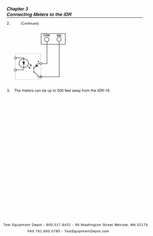
The two jacks at the top center of the rear panel on the RS-232 Key/ modem are for connecting to the phone line. Connect one of these two jacks to the telephone line.
IMPORTANT: The telephone line should be dedicated exclusively to the automatic meter reading system. Never connect to a phone line that has other modems or fax machines connected. If there are telephones connected to this phone line, the proprietor must be aware that all phones must be on "hook" in order for the modem to work. A dedicated telephone line is suggested for system reliability.
E. Using the RS-232 Key with an external modem
1. All IDRs should be connected to the RS-232 Key as explained in the previous section about connecting IDRs to the RS-232 Key.
2. DISCONNECT POWER TO THE RS-232 KEY. Remove the cover by removing the 2 screws from the bottom of the enclosure.
3. On the circuit board, locate jumpers J7 (MODEM) and J8 (ex-MODEM). If these jumpers are set in the DIRECT position, you must move the jumpers so they are set in the MODEM position. Replace the cover and secure the enclosure.
4. Connect the RS-232 Key 2000 to the external modem using the supplied 8-conductor flat modular cable.
5. Connect the 7VAC adapter to the power input on the back of the RS-232 Key and plug it into a 120VAC outlet.
IMPORTANT: The modem should use a phone line that is dedicated exclu- sively to the AMR system. Do not use a phone line that is shared by another modem or fax machine.
Test Equipment Depot - 800.517.8431 - 99 Washington Street Melrose, MA 02176
FAX 781.665.0780 - TestEquipmentDepot.com

Chapter 6Serial Communications
F. Baud Rate Selection
The communication baud rate is selected by means of a jumper on the circuit board. (See Appendix C for location.) There are three (3) selections: 19200, 9600 (factory default) and 2400.
1. When using the IDR with a modem, the rate of 9600 should always be selected.
2. The baud rate on the IDR must always match the baud rate selected in the RightEnergyTM software. Communications will not work if they are not set correctly.
3. After a baud rate change, press CPU Reset (see Appendix C) to register the change in the IDR.
4. All IDRs in the "daisy chain" circuit must be set at the same baud rate.
Test Equipment Depot - 800.517.8431 - 99 Washington Street Melrose, MA 02176
FAX 781.665.0780 - TestEquipmentDepot.com
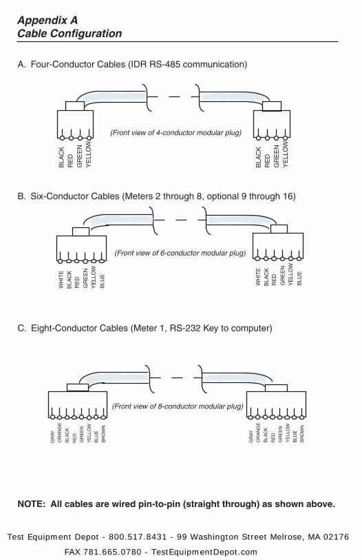
A. Four-Conductor Cables (IDR RS-485 communication)
B. Six-Conductor Cables (Meters 2 through 8, optional 9 through 16)
C. Eight-Conductor Cables (Meter 1, RS-232 Key to computer)
NOTE: All cables are wired pin-to-pin (straight through) as shown above.
Appendix ACable Configuration
BLA
CK
RE
DG
RE
EN
YE
LLO
W
BLA
CK
RE
DG
RE
EN
YE
LLO
W
BLA
CK
RE
D
GR
EE
N
YE
LLO
W
WH
ITE
BLU
E
BLA
CK
RE
D
GR
EE
N
YE
LLO
W
WH
ITE
BLU
E
BLA
CK
RE
D
GR
EE
N
YE
LLO
W
GR
AY
BLU
E
OR
AN
GE
BR
OW
N
BLA
CK
RE
D
GR
EE
N
YE
LLO
W
GR
AY
BLU
E
OR
AN
GE
BR
OW
N
(Front view of 4-conductor modular plug)
(Front view of 6-conductor modular plug)
(Front view of 8-conductor modular plug)
Test Equipment Depot - 800.517.8431 - 99 Washington Street Melrose, MA 02176
FAX 781.665.0780 - TestEquipmentDepot.com
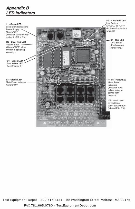
Appendix BLED Indicators
L1 - Green LEDSerial Communications Power SupplyAlways "ON"(Indicates power supplyis okay if LED is ON.)
D6 - Clear Red LEDSystem Error(Always "OFF" whensystem is operating normally.)
D1 - Green LEDD2 - Yellow LEDSee Chapter 6.
L3 - Green LEDMain Power IndicatorAlways "ON"
D7 - Clear Red LEDLow BatterySHOULD be "OFF"(Indicates low batterywhen lit.)
D4 - Red LEDCPU Status(Flashes once per second.)
P1-P8 - Yellow LEDMeter Pulse Indicators(Indicates input pulses being re-ceived from meters.)
IDR-16 will havean additional set of yellow LEDs(labeled P9 - P16).
Test Equipment Depot - 800.517.8431 - 99 Washington Street Melrose, MA 02176
FAX 781.665.0780 - TestEquipmentDepot.com

J3-J4 - RS-485 Communications Jacks
Baud Rate SelectionSee Chapter 6.
(Selects communication baud rate; rate is ALWAYS set at 9600 bps when modem is present.)
Baud Rate SelectionSee Chapter 6 d"Communications"
TB9 - External Power InputSee Chapter 5.
(Connects externalpower supply adapter.)
JMP - 8-Meter Power SelectionSee Chapters 4 and 5.
(Selects external power, orpowered from Meter 1.)
J23 & J24 - Input PowerSelectionSee Chapters 4 and 5.
CPU Reset Button
M1-M8 - Meter Inputs(Ports used to connectmeters to IDR)
IDR-16 will have 8additional inputs.See Chapter 1.
J20 - RS-485 CommunicationsSee Chapter 6.
BatterySee Chapter 6.
(Ports used to connect one IDRto another IDR or to an RS-232 Key)
Appendix CIDR Circuit Board Components
Test Equipment Depot - 800.517.8431 - 99 Washington Street Melrose, MA 02176
FAX 781.665.0780 - TestEquipmentDepot.com

Appendix DSystem Wiring Guides
Note: E-Mon will supply and install end connectors to cables during startup.
Note: Meter 1 must be installed within 100 feet of IDR. Meters 2-8 must be installed within 500 feet of IDR.
(Up to 8 Meters)
(One of three channels shown for clarity.) (Up to 8 Meters)
~~
Channel 1 of 3
4-ConductorFlat Modular Cable
Up to 4000 Feet Total
Daisy-Chain or Star Connection
Up to 52 IDRs per channel
AC Adapter
RS-232Key*
6' cable provided byE-Mon (15 ft max.)8-conductor cable
& modular plug
DB-9 (DTE) Connector
IBM PC/XT/ATor Compatible
RJ-45
RJ-11
8-Cond.RJ-45
RJ-11
6-Cond.RJ-45
6-Cond.RJ-45
Wiring Guide for IDR-8
IDR A
IDR Z
CONNECTION CABLE TYPE CONNECTOR
IDR to E-Mon D-Mon® Meter #1 8-cond. 22-26 AWG RJ-45 flat modular cable
IDR to E-Mon D-Mon Meters #2-8 6-cond. 22-26 AWG RJ-45 (Pins 1 & 8 not used)
IDR to IDR 4-cond. 26 AWG RJ-11
IDR to RS-232 Key 2000 4-cond. 26 AWG RJ-11
RS-232 Key 2000 to Computer** 8-cond. 22-26 AWG RJ-45/DTE flat modular cable
RS-232 Key 2000 to Modem ** 8-cond. 22-26 AWG RJ-45 flat modular cable
IDR to Pulse Meter 2-cond. 14-22 AWG
** Supplied by E-MonNote: Interior interconnecting communications are supplied with the pre-wired MMU-type metering cabinets.Note: When constructing field-installed cables, modular cables must be made so that the individual wires go through on the same pin number.
* Contact E-Mon for USB-only connection.
Test Equipment Depot - 800.517.8431 - 99 Washington Street Melrose, MA 02176
FAX 781.665.0780 - TestEquipmentDepot.com

Note: E-Mon will supply and install end connectors to cables during startup.
Note: Meter 1 must be installed within 100 feet of IDR. Meters 2-8 must be installed within 500 feet of IDR.
(Up to 16 Meters)
(One of three channels shown for clarity.) (Up to 16 Meters)
~~
Channel 1 of 3
4-ConductorFlat Modular Cable
Up to 4000 Feet Total
Daisy-Chain or Star Connection
Up to 26 IDRs per channel(3 channels per RS-232 Key)
AC Adapter
RS-232Key*
6' cable provided byE-Mon (15 ft max.)8-conductor cable
& modular plug
DB-9 (DTE) Connector
IBM PC/XT/ATor Compatible
RJ-45
RJ-11
8-Cond.RJ-45
RJ-11
6-Cond.RJ-45
6-Cond.RJ-45
Wiring Guide for IDR-16
IDR A-B
IDR Y-Z
CONNECTION CABLE TYPE CONNECTOR
IDR to E-Mon D-Mon® Meter #1 8-cond. 22-26 AWG RJ-45 flat modular cable
IDR to E-Mon D-Mon Meters #2-16 6-cond. 22-26 AWG RJ-45 (Pins 1 & 8 not used)
IDR to IDR 4-cond. 26 AWG RJ-11
IDR to RS-232 Key 2000 4-cond. 26 AWG RJ-11
RS-232 Key 2000 to Computer** 8-cond. 22-26 AWG RJ-45/DTE flat modular cable
RS-232 Key 2000 to Modem ** 8-cond. 22-26 AWG RJ-45 flat modular cable
IDR to Pulse Meter 2-cond. 14-22 AWG
** Supplied by E-MonNote: Interior interconnecting communications are supplied with the pre-wired MMU-type metering cabinets.Note: When constructing field-installed cables, modular cables must be made so that the individual wires go through on the same pin number.
* Contact E-Mon for USB-only connection.
3rd PartyMeter
3rd PartyMeter
3rd PartyMeter
Pair of wires(#22-#14 AWG)
Appendix DSystem Wiring Guides
Test Equipment Depot - 800.517.8431 - 99 Washington Street Melrose, MA 02176
FAX 781.665.0780 - TestEquipmentDepot.com
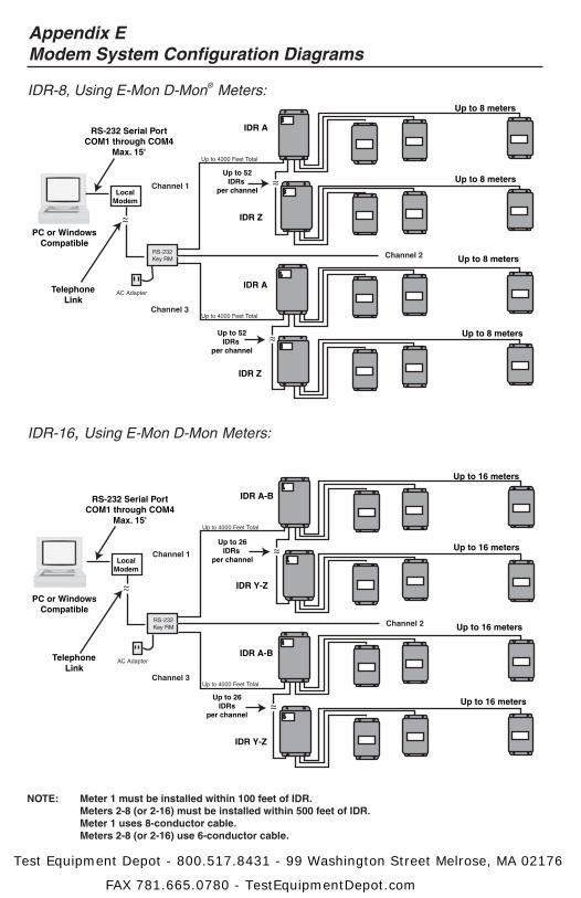
Appendix EModem System Configuration Diagrams
NOTE: Meter 1 must be installed within 100 feet of IDR. Meters 2-8 (or 2-16) must be installed within 500 feet of IDR. Meter 1 uses 8-conductor cable. Meters 2-8 (or 2-16) use 6-conductor cable.
RS-232 Serial PortCOM1 through COM4
Max. 15'
PC or WindowsCompatible
LocalModem
TelephoneLink
Up to 26IDRs
per channel
Up to 26IDRs
per channel
IDR A-B
IDR Y-Z
IDR A-B
IDR Y-Z
Up to 16 meters
Up to 16 meters
Up to 16 meters
IDR-16, Using E-Mon D-Mon Meters:
Channel 2
~~
~~Channel 1
Up to 4000 Feet Total
Up to 4000 Feet Total
AC Adapter
RS-232Key RM
Up to 16 meters
Channel 3
~~
RS-232 Serial PortCOM1 through COM4
Max. 15'
PC or WindowsCompatible
LocalModem
TelephoneLink
Up to 52IDRs
per channel
Up to 52IDRs
per channel
IDR A
IDR Z
IDR A
IDR Z
Up to 8 meters
Up to 8 meters
Up to 8 meters
IDR-8, Using E-Mon D-Mon® Meters:
Channel 2
~~
~~Channel 1
Up to 4000 Feet Total
Up to 4000 Feet Total
AC Adapter
RS-232Key RM
Up to 8 meters
Channel 3
~~
Test Equipment Depot - 800.517.8431 - 99 Washington Street Melrose, MA 02176
FAX 781.665.0780 - TestEquipmentDepot.com

Appendix FHardwired System Configuration Diagrams
Up to 8 Meters
Up to 8 Meters
Channel 2
~~
~~Channel 1
Channel 3
Up to 4000 Feet Total
Up to 4000 Feet Total
Up to 26IDRs
Up to 26 IDRs
NOTE: Meter #1 must be installed within 100 feet of IDR. Meters #2-16 must be installed within 500 feet of IDR.
Meter #1 uses 8-conductor cable. Meters #2-16 use 6-conductor cable.
AC Adapter
RS-232Key*
RS-232 Serial PortCOM1 or COM2
IBM PC/XT/ATor Compatible
Up to 8 Meters
Up to 8 Meters
15’ max
IDR-8, Using E-Mon D-Mon® Meters:
IDR
IDR
IDR
IDR
Test Equipment Depot - 800.517.8431 - 99 Washington Street Melrose, MA 02176
FAX 781.665.0780 - TestEquipmentDepot.com
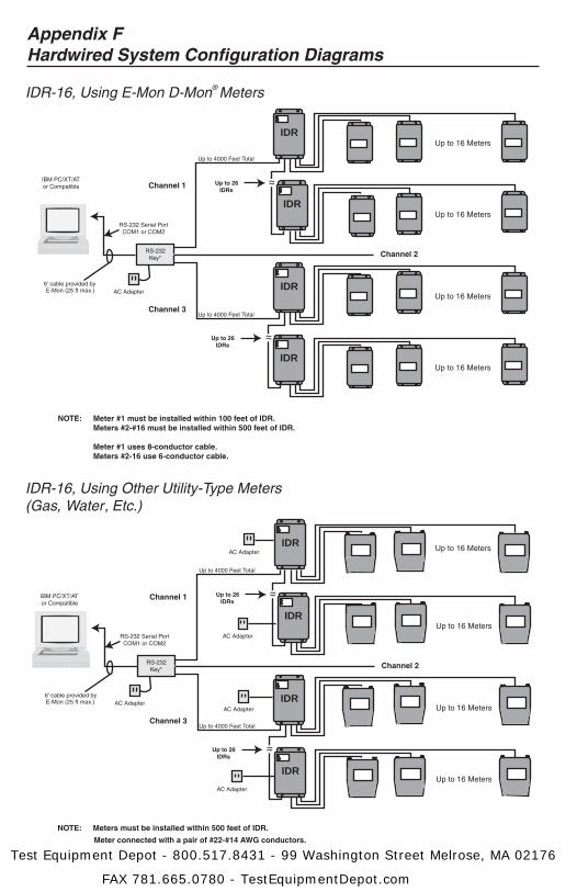
Appendix FHardwired System Configuration Diagrams
IDR-16, Using Other Utility-Type Meters(Gas, Water, Etc.)
Up to 16 Meters
Up to 16 Meters
Channel 2
~~
~~Channel 1
Channel 3
Up to 4000 Feet Total
Up to 4000 Feet Total
Up to 26IDRs
Up to 26 IDRs
NOTE: Meters must be installed within 500 feet of IDR.
Meter connected with a pair of #22-#14 AWG conductors.
AC Adapter
RS-232Key*
6' cable provided byE-Mon (25 ft max.)
RS-232 Serial PortCOM1 or COM2
IBM PC/XT/ATor Compatible
Up to 16 Meters
Up to 16 Meters
IDR-16, Using E-Mon D-Mon® Meters
Up to 16 Meters
Up to 16 Meters
Channel 2
~~
~~Channel 1
Channel 3
Up to 4000 Feet Total
Up to 4000 Feet Total
Up to 26IDRs
Up to 26 IDRs
NOTE: Meter #1 must be installed within 100 feet of IDR. Meters #2-#16 must be installed within 500 feet of IDR.
Meter #1 uses 8-conductor cable. Meters #2-16 use 6-conductor cable.
AC Adapter
RS-232Key*
6' cable provided byE-Mon (25 ft max.)
RS-232 Serial PortCOM1 or COM2
IBM PC/XT/ATor Compatible
Up to 16 Meters
Up to 16 Meters
AC Adapter
AC Adapter
AC Adapter
AC Adapter
IDR
IDR
IDR
IDR
IDR
IDR
IDR
IDR
Test Equipment Depot - 800.517.8431 - 99 Washington Street Melrose, MA 02176
FAX 781.665.0780 - TestEquipmentDepot.com
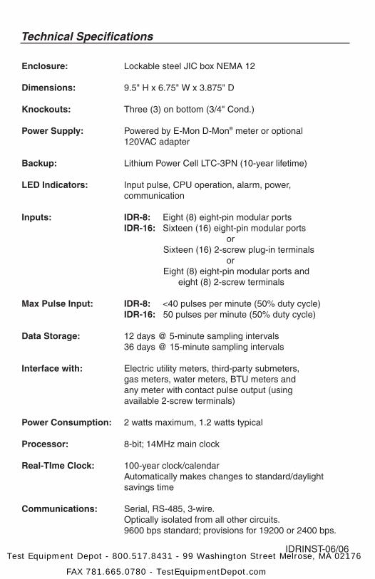
Technical Specifications
Enclosure: Lockable steel JIC box NEMA 12
Dimensions: 9.5" H x 6.75" W x 3.875" D
Knockouts: Three (3) on bottom (3/4" Cond.)
Power Supply: Powered by E-Mon D-Mon® meter or optional 120VAC adapter
Backup: Lithium Power Cell LTC-3PN (10-year lifetime)
LED Indicators: Input pulse, CPU operation, alarm, power, communication
Inputs: IDR-8: Eight (8) eight-pin modular ports IDR-16: Sixteen (16) eight-pin modular ports or Sixteen (16) 2-screw plug-in terminals or Eight (8) eight-pin modular ports and eight (8) 2-screw terminals
Max Pulse Input: IDR-8: <40 pulses per minute (50% duty cycle) IDR-16: 50 pulses per minute (50% duty cycle)
Data Storage: 12 days @ 5-minute sampling intervals 36 days @ 15-minute sampling intervals
Interface with: Electric utility meters, third-party submeters, gas meters, water meters, BTU meters and any meter with contact pulse output (using available 2-screw terminals)
Power Consumption: 2 watts maximum, 1.2 watts typical
Processor: 8-bit; 14MHz main clock
Real-TIme Clock: 100-year clock/calendar Automatically makes changes to standard/daylight savings time
Communications: Serial, RS-485, 3-wire. Optically isolated from all other circuits. 9600 bps standard; provisions for 19200 or 2400 bps.
IDRINST-06/06Test Equipment Depot - 800.517.8431 - 99 Washington Street Melrose, MA 02176
FAX 781.665.0780 - TestEquipmentDepot.com