Embed Size (px)
Citation preview
No header here
No header
No footer
Intraplex® HD Link™ RF Studio-to-Transmitter Link Installation & Operation Manual
HD Link Studio-to-Transmitter Link
Version 2.2
TOTAL CONTENT DELIVERY SOLUTIONS | Managing content. Delivering results.
No header here
No header
No footer
Intraplex® HD Link™ RF Studio-to-Transmitter Link Installation & Operation Manual Version 2.2, December 2011
© Copyright 2009-2011 Harris Corporation. All rights reserved.
Reproduction, adaptation, or translation without prior written permission is prohibited, except as allowed under the copyright laws.
Warranty
The information contained in this document is subject to change without notice. Harris makes no warranty of any kind with regard to this material, including, but not limited to, the implied warranties of merchantability and fitness for a particular purpose.
Harris shall not be liable for errors contained herein or for incidental or consequential damage in connection with the furnishing, performance, or use of this material.
Trademark Credits
AudioLink PLUS™, HD Link™, IntraGuide®, Intraplex®, NetXpress™, NetXpress LX™, STL PLUS®, SynchroCast®, and SynchroCast3™ are trademarks of Harris Corporation. Other trademarks are the property of their respective owners.
How to Contact Us
Harris Corporation Intraplex Products 5300 Kings Island Drive, Suite 101 Mason, OH 45040 USA
Sales: +1 513 459 3400
Fax: +1 513 701 5316
E-mail: [email protected]
Web: www.broadcast.harris.com
How to Get Support
If you have a technical question or issue with your Intraplex Products equipment, please check our customer support Web page: http://ecustomer.broadcast.harris.com/ecustomer_enu
You can also call the Customer Support line or send non-emergency e-mail:
● U.S., Canada, and Latin America: +1-217-222-8200 or [email protected]
● Europe, Middle East, and Africa: +44-118-967-8100 or [email protected]
● Asia and Pacific Rim: +852-2776-0628 or [email protected]
Versions
With few exceptions, the version number of this manual matches the version of the latest product release. Minor release numbers, such as Version 1.01, reflect minor manual changes not related to the product release.
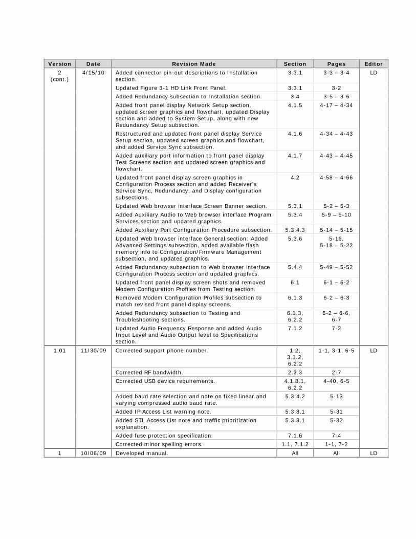
Version Date Revision Made Section Pages Editor
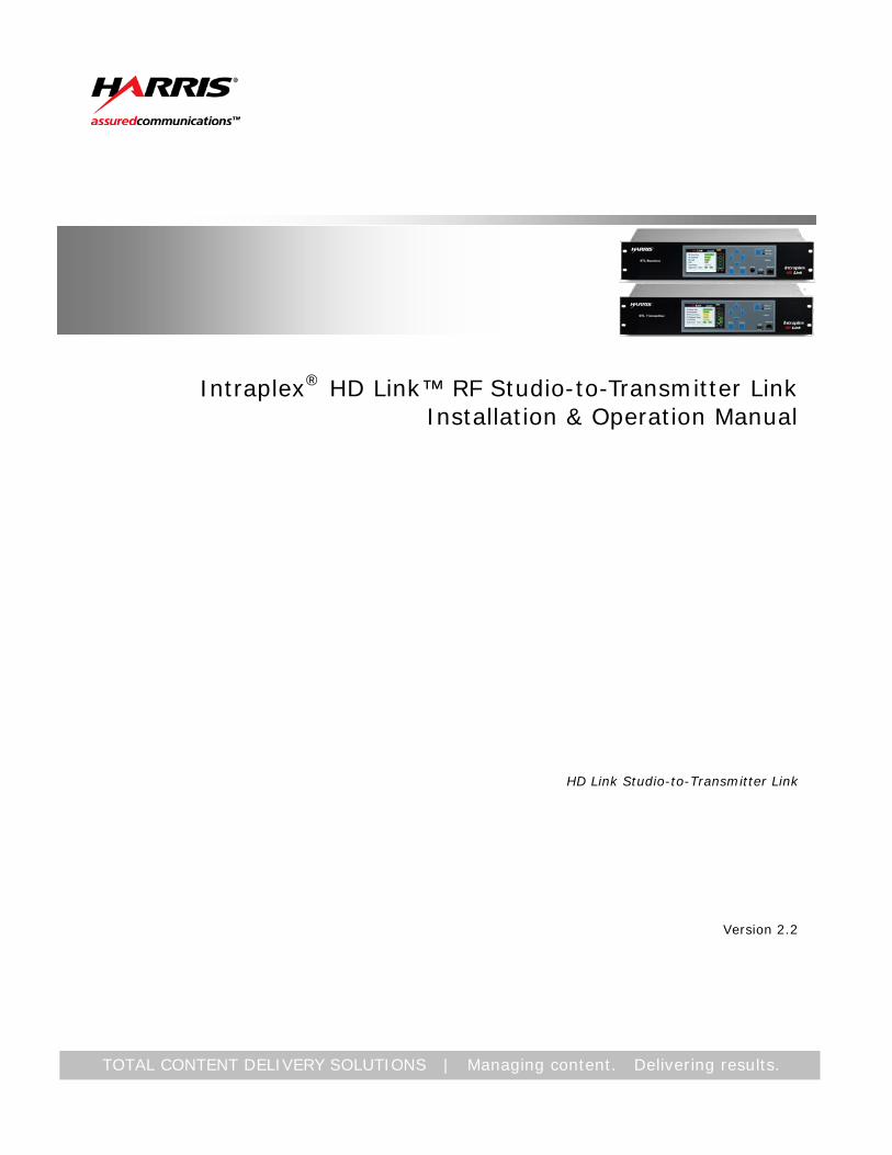
2.2 12/6/11 Moved New Features subsection into HD Link Features subsection of the Functional Design section.
2.3 – 2.4 2-6 – 2-10 LD
Added IP Path Redundancy subsection for new feature. 2.3.8 2-9 – 2-10
Reorganized Front Panel Configuration & Operation section, moving initial procedures to beginning, followed by field descriptions and operation instructions.
4 4-1 – 4-64
Updated Configure Redundant Transmitters subsection to reflect current procedure.
4.1.6.1 4-5 – 4-6
Updated Status 2 screen shots to show updated screens. 4.4.4.7 4-29 Added Status Screen 3 and Path Redundancy screens to show new screens and added information on new feature.
4.4.4.9 4-30 – 4-31
Updated Service Profile field descriptions to match fields. 4.4.6.2 4-45 – 4-46
Reorganized Web Browser Interface Configuration & Operation section, moving initial procedures to beginning, followed by field descriptions and operation instructions.
5 5-1 – 5-66
Added Program Services page showing backup profile to Figure 5-24.
5.6.4 5-25
Added Path Redundancy subsection for new feature. 5.6.6.3 5-37 – 5-39
Added File Manager and Traceroute subsections for new utilities.
5.6.10 5-69 – 5-72
No header here
No header
No footer
Version Date Revision Made Section Pages Editor
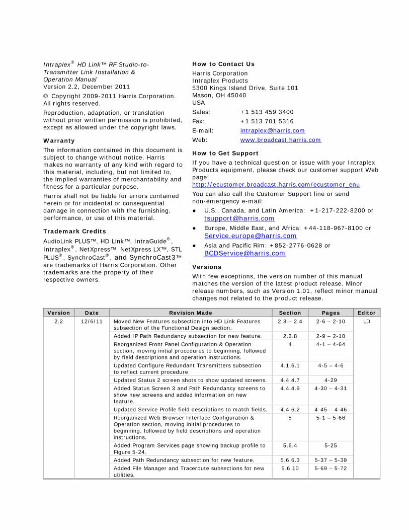
2.1 11/29/10 Reworked Key Features list. 1.1 1-1 LD
Added detail to Audio Transport feature subsection from New Features – Software Release 2.0 subsection.
2.3.1 2-6
Added 2.3.3 – In-band Messaging and Synchronization subsection from New Features – Software Release 2.0 subsection.
2.3.3 2-7
Changed 2.4 – New Features – Software Release 2.0 to New Features – Software Release 2.1 and updated content.
2.4 2-9 – 2-11
Updated redundant transmitter-main/alt controller connection procedure to match HD Link Main/Alt Controller appendix and added connection diagram.
3.4.1 3-6 – 3-7
Added Repeater Installation & Wiring section. 3.5 3-8 Added to front panel display status message letter list. 4.1.3 4-4
Added Repeater Setup to flowchart and Repeater Setup screens and discussion to System Setup Screens subsection, rewrote part of subsection, and updated screen graphics to reflect screen changes.
4.1.5
4-17 – 4-21, 4-26 – 4-28
Added Ethernet Rate Policing to flowchart and Ethernet Rate Policing screens and discussion to Service Setup subsection, rewrote part of subsection, and updated screen graphics to reflect change.
4.1.6 4-29 – 4-37
Rewrote redundant transmitter and redundant receiver configuration procedures to reflect screen changes and updated screen graphics.
4.2.6.1 4.2.6.2
4-56 – 4-59
Added Configure the Systems for Repeater Mode section. 4.2.7 4-57 – 4-60
Updated screen graphics for Inactivity Timer. 4.2.8.2 4.2.8.3
4-61 – 4-62
Updated Figure 5-12 graphic and field definitions to reflect screen changes.
5.3.5 5-16
Updated Figure 5-14 graphics and field definitions to reflect screen changes.
5.3.6.2 5-20 – 5-21
Updated Performance menu, added Ethernet Interfaces and Aux Audio Channels subsections, and updated Packet Statistics graphic and definitions to reflect screen changes.
5.3.9 5-38 – 5-40, 5-42 – 5-44
Updated receiver radio link parameter configuration procedure and graphic to reflect screen changes.
5.4.2 5-52
Updated graphic in redundant transmitter configuration procedure to reflect screen changes.
5.4.4.1 5-54
Updated graphic in redundant receiver configuration procedure to reflect screen changes.
5.4.4.2 5-57
Updated Test front panel display screen graphics. 6 6-1 – 6-2
Added Repeater Testing section. 6.1.4 6-6 – 6-8
Added Troubleshooting tip for inability to power down RF on front panel.
6.2.1 6-8 – 6-9
Corrected Main Analog Audio apt-X spec to match linear. 7 7-2
Added Appendix B – HD Link Redundancy. B B-1 – B-3
Added Appendix C – HD Link Main/Alt Controller. C C-1 – C-12 Added Appendix D – HD Link Module Kit Installation Instructions.
D D-1 – D-2
2 4/15/10 Updated front panel display screen graphics and changed steps to match updated screens.
QSG 1-2 LD
Added in-band configuration and redundancy features to Features list.
1.1 1-1
Added New Features subsection. 2.4 2-7 – 2-8
No header here
No header
No footer
Version Date Revision Made Section Pages Editor
2 (cont.)
4/15/10 Added connector pin-out descriptions to Installation section.
3.3.1 3-3 – 3-4 LD
Updated Figure 3-1 HD Link Front Panel. 3.3.1 3-2
Added Redundancy subsection to Installation section. 3.4 3-5 – 3-6
Added front panel display Network Setup section, updated screen graphics and flowchart, updated Display section and added to System Setup, along with new Redundancy Setup subsection.
4.1.5 4-17 – 4-34
Restructured and updated front panel display Service Setup section, updated screen graphics and flowchart, and added Service Sync subsection.
4.1.6 4-34 – 4-43
Added auxiliary port information to front panel display Test Screens section and updated screen graphics and flowchart.
4.1.7 4-43 – 4-45
Updated front panel display screen graphics in Configuration Process section and added Receiver’s Service Sync, Redundancy, and Display configuration subsections.
4.2 4-58 – 4-66
Updated Web browser interface Screen Banner section. 5.3.1 5-2 – 5-3
Added Auxiliary Audio to Web browser interface Program Services section and updated graphics.
5.3.4 5-9 – 5-10
Added Auxiliary Port Configuration Procedure subsection. 5.3.4.3 5-14 – 5-15
Updated Web browser interface General section: Added Advanced Settings subsection, added available flash memory info to Configuration/Firmware Management subsection, and updated graphics.
5.3.6 5-16, 5-18 – 5-22
Added Redundancy subsection to Web browser interface Configuration Process section and updated graphics.
5.4.4 5-49 – 5-52
Updated front panel display screen shots and removed Modem Configuration Profiles from Testing section.
6.1 6-1 – 6-2
Removed Modem Configuration Profiles subsection to match revised front panel display screens.
6.1.3 6-2 – 6-3
Added Redundancy subsection to Testing and Troubleshooting sections.
6.1.3, 6.2.2
6-2 – 6-6, 6-7
Updated Audio Frequency Response and added Audio Input Level and Audio Output level to Specifications section.
7.1.2 7-2
1.01 11/30/09 Corrected support phone number. 1.2, 3.1.2, 6.2.2
1-1, 3-1, 6-5 LD
Corrected RF bandwidth. 2.3.3 2-7
Corrected USB device requirements. 4.1.8.1, 6.2.2
4-40, 6-5
Added baud rate selection and note on fixed linear and varying compressed audio baud rate.
5.3.4.2 5-13
Added IP Access List warning note. 5.3.8.1 5-31
Added STL Access List note and traffic prioritization explanation.
5.3.8.1 5-32
Added fuse protection specification. 7.1.6 7-4
Corrected minor spelling errors. 1.1, 7.1.2 1-1, 7-2
1 10/06/09 Developed manual. All All LD
No header here
Harris Corporation i Intraplex Products
Table of Contents
Section 1 – Introduction ................................................................ 1-1
1.1 Key Features .................................................................................... 1-1
1.2 Manual Use ...................................................................................... 1-1
1.3 Manual Scope ................................................................................... 1-2
1.4 System Components ......................................................................... 1-2 1.4.1 Transmitter and Receiver ........................................................................1-2 1.4.2 Front Panel Interface ..............................................................................1-2 1.4.3 Web Browser Interface ...........................................................................1-3
Section 2 – Functional Design ........................................................ 2-1
2.1 General System Description ............................................................... 2-1
2.2 High Definition (HD) STL Development ................................................ 2-1 2.2.1 Modulation ............................................................................................2-1 2.2.2 HD Radio Signal on an STL ......................................................................2-2 2.2.3 Data Bandwidth Requirements .................................................................2-2 2.2.4 STL Carrying Capacity ............................................................................2-2 2.2.5 Data Quality ..........................................................................................2-3 2.2.6 Network Topology Support ......................................................................2-5
2.3 HD Link Features ............................................................................. 2-6 2.3.1 Audio Transport .....................................................................................2-6 2.3.2 Data Transport ......................................................................................2-6 2.3.3 In-band Messaging and Synchronization ...................................................2-7 2.3.4 RF Performance .....................................................................................2-7 2.3.5 Setup and Operation ..............................................................................2-8 2.3.6 Connectors and Display ..........................................................................2-8 2.3.7 Redundancy ..........................................................................................2-8 2.3.8 IP Path Redundancy ...............................................................................2-9 2.3.9 Software-based STL Repeater ............................................................... 2-12
Section 3 – Installation ................................................................. 3-1
3.1 Installation Preparation...................................................................... 3-1 3.1.1 Tools and Cables Required ......................................................................3-1 3.1.2 Equipment Unpacking and Inspection .......................................................3-1
3.2 Transmitter and Receiver Installation .................................................. 3-1
3.3 Wiring and External Connections ......................................................... 3-2 3.3.1 Available Connections ............................................................................3-2 3.3.2 Required Connections .............................................................................3-5
3.4 Redundancy Installation and Wiring .................................................... 3-5 3.4.1 Redundant Transmitters .........................................................................3-6 3.4.2 Redundant Receivers .............................................................................3-8
3.5 Repeater Installation and Wiring ......................................................... 3-8
3.6 Unit Powering .................................................................................. 3-8
HD Link Installation & Operation Manual Table of Contents Version 2.2, December 2011
ii Harris Corporation Intraplex Products
3.6.1 Power Supplies ......................................................................................3-9 3.6.2 Radio Frequency Power Status ................................................................3-9
Section 4 – Front Panel Display Configuration & Operation ........... 4-1
4.1 Configuration Procedures ................................................................... 4-2 4.1.1 Configure the HD Port ............................................................................4-2 4.1.2 Configure the LAN Port ...........................................................................4-3 4.1.3 Configure the RF Profile Parameters .........................................................4-3 4.1.4 Configure the Service Profile Parameters ..................................................4-4 4.1.5 Configure the Receiver’s Service Sync ......................................................4-4 4.1.6 Configure the System for Redundancy ......................................................4-5 4.1.7 Configure the System for Repeater Mode ..................................................4-8 4.1.8 Set or Unlock the Display...................................................................... 4-10
4.2 Operation Guidelines ........................................................................ 4-13
4.3 Upgrade Procedure .......................................................................... 4-13
4.4 Front Panel Buttons and Screens....................................................... 4-14 4.4.1 Panel Buttons and Screen Navigation ..................................................... 4-14 4.4.2 Initial Screen ....................................................................................... 4-15 4.4.3 Main Screen and Screen Components ..................................................... 4-16 4.4.4 Status Screens .................................................................................... 4-18 4.4.5 System Setup Screens .......................................................................... 4-31 4.4.6 Service Setup Screens .......................................................................... 4-43 4.4.7 Test Screens ....................................................................................... 4-49 4.4.8 Firmware and File Management Screens ................................................. 4-51
Section 5 – Web Browser Interface Configuration & Operation ..... 5-1
5.1 Browser Compatibility ....................................................................... 5-1
5.2 Interface Access .............................................................................. 5-1
5.3 Configuration Process ....................................................................... 5-2 5.3.1 Configure the HD Port and the LAN Port ...................................................5-2 5.3.2 Configure the Radio Link Parameters ........................................................5-2 5.3.3 Configure the Program Services Parameters ..............................................5-4 5.3.4 Configure the Systems for Redundancy ....................................................5-7 5.3.5 Configure the Systems for Repeater Mode .............................................. 5-13
5.4 Operation Guidelines ...................................................................... 5-14
5.5 Upgrade Procedure ......................................................................... 5-15
5.6 Interface Pages .............................................................................. 5-16 5.6.1 Screen Banner .................................................................................... 5-16 5.6.2 Navigation Bar .................................................................................... 5-17 5.6.3 Alarms ............................................................................................... 5-18 5.6.4 Program Services ................................................................................ 5-22 5.6.5 Radio Link .......................................................................................... 5-28 5.6.6 General Configurations ......................................................................... 5-31 5.6.7 Network Configurations ........................................................................ 5-47 5.6.8 Security Configurations ........................................................................ 5-54 5.6.9 Performance ....................................................................................... 5-59 5.6.10 Utilities ............................................................................................... 5-71
Table of Contents HD Link Installation & Operation Manual Version 2.2, December 2011
Harris Corporation iii Intraplex Products
Section 6 – Testing & Troubleshooting ......................................... 6-1
6.1 Testing ........................................................................................... 6-1 6.1.1 Test Tone ..............................................................................................6-1 6.1.2 Audio Port Monitor .................................................................................6-1 6.1.3 Redundancy Testing ...............................................................................6-2 6.1.4 Repeater Testing ...................................................................................6-6
6.2 Troubleshooting ................................................................................ 6-8 6.2.1 General Guidelines .................................................................................6-8 6.2.2 Redundancy Guidelines ..........................................................................6-9 6.2.3 Possible Error Messages ....................................................................... 6-10
Section 7 – Specifications .............................................................. 7-1
7.1 Detailed Specifications ...................................................................... 7-1 7.1.1 Radio Frequency (RF) .............................................................................7-1 7.1.2 Audio Performance .................................................................................7-1 7.1.3 System .................................................................................................7-3 7.1.4 Networking ...........................................................................................7-3 7.1.5 Control and Monitoring ...........................................................................7-3 7.1.6 Mechanical and Environmental .................................................................7-4
7.2 Notice of FCC Compliance ................................................................. 7-4 7.2.1 Compliance with FCC Part 15 Requirements ..............................................7-4 7.2.2 Compliance with FCC Part 74 Requirements ..............................................7-4
Section 8 – Glossary ...................................................................... 8-1
Appendix A – Services & Minimum Rx Signal Level ........................ A-1
Appendix B – HD Link Main/Alt Controller ..................................... B-1
B.1 Installation ...................................................................................... B-1 B.1.1 Installation Preparation ......................................................................... B-1 B.1.2 Main/Alt Controller Wiring ...................................................................... B-2 B.1.3 Wiring and Interconnection with HD Link Transmitters............................... B-6 B.1.4 Switches and Indicator Lights ................................................................. B-7 B.1.5 Power ................................................................................................. B-8
B.2 Setup & Operation ............................................................................ B-9 B.2.1 Initial Setup ......................................................................................... B-9 B.2.2 Power Up Configuration ......................................................................... B-9 B.2.3 Transmitter Switchover ........................................................................ B-10
B.3 Specifications ................................................................................ B-10 B.3.1 Detailed Specifications ......................................................................... B-10 B.3.2 Compliance with FCC Part 15 Requirements ............................................ B-11
Appendix C – HD Link Redundancy Alternatives ............................ C-1
C.1 HD Link Transmitters and Main/Alt Controllers ..................................... C-1
C.2 HD Link Receivers and External Controllers ......................................... C-2
HD Link Installation & Operation Manual Table of Contents Version 2.2, December 2011
iv Harris Corporation Intraplex Products
Appendix D – HD Link Module Installation Instructions ................. D-1
Figures
Figure 1-1. HD Link Receiver Front Panel with Headphone Jack .....................................1-2 Figure 2-1. HD Link STL IP Gateway Architecture ........................................................2-4 Figure 2-2. Network Topology with Return Path ..........................................................2-5 Figure 2-3. Transmitter Redundancy ..........................................................................2-8 Figure 2-4. Receiver Redundancy ..............................................................................2-9 Figure 2-5. Full Duplex IP Path................................................................................ 2-11 Figure 2-6. Simplex IP Path .................................................................................... 2-11 Figure 2-7. HD Link Software-based Repeater Configuration ....................................... 2-13 Figure 3-1. HD Link Front Panel with Connectors – Receiver .........................................3-2 Figure 3-2. HD Link Transmitter and Receiver – Rear View ...........................................3-2 Figure 3-3. Contact Input Circuitry ............................................................................3-4 Figure 3-4. HD Link Transmitters Connecting to an HD Link Main/Alt Controller ...............3-7 Figure 3-5. HD Link Transmitter and Receiver – Rear View ...........................................3-8 Figure 3-6. Initial Front Panel Display Screen ..............................................................3-9 Figure 3-7. Transmitter RF Link Detail Screen ........................................................... 3-10 Figure 4-1. Main Screen System Setup ...................................................................4-2 Figure 4-2. System Setup Network Setup ...............................................................4-2 Figure 4-3. HD Port .................................................................................................4-2 Figure 4-4. LAN Port ................................................................................................4-3 Figure 4-5. Main Service Setup..............................................................................4-3 Figure 4-6. RF Profile – Transmitter and Receiver ........................................................4-4 Figure 4-7. Service Setup Service Profile ................................................................4-4 Figure 4-8. Service Setup Service Sync ..................................................................4-5 Figure 4-9. System Setup Network Setup – Transmitter ...........................................4-5 Figure 4-10. HD Port – Transmitter ...........................................................................4-6 Figure 4-11. HD Port – Receiver ................................................................................4-7 Figure 4-12. System Setup Redundancy Setup – Receiver ........................................4-7 Figure 4-13. Main System Setup – Receiver ............................................................4-8 Figure 4-14. System Setup Repeater Setup – Receiver .............................................4-8 Figure 4-15. Firmware and File Management Restart System ....................................4-9 Figure 4-16. System Setup Repeater Setup – Transmitter ........................................4-9 Figure 4-17. Firmware and File Management Restart System .................................. 4-10 Figure 4-18. Main System Setup .......................................................................... 4-10 Figure 4-19. System Setup Display ...................................................................... 4-11 Figure 4-20. Display Brightness ........................................................................... 4-11 Figure 4-21. Display Inactivity Timer ................................................................... 4-11 Figure 4-22. Action on Timeout ............................................................................... 4-12 Figure 4-23. Firmware Upgrade ............................................................................... 4-13 Figure 4-24. Example Select File ............................................................................. 4-13 Figure 4-25. HD Link Front Panel – Receiver ............................................................. 4-14 Figure 4-26. Initial Screen – Transmitter and Receiver ............................................... 4-15 Figure 4-27. Main Menu Screen ............................................................................... 4-16 Figure 4-28. Main Status – Transmitter and Receiver ............................................. 4-18 Figure 4-29. Status Levels Flow Chart ...................................................................... 4-20 Figure 4-30. Status Audio Port 1 – Transmitter and Receiver .................................. 4-21 Figure 4-31. Status Audio Port 2 – Transmitter and Receiver .................................. 4-22
Table of Contents HD Link Installation & Operation Manual Version 2.2, December 2011
Harris Corporation v Intraplex Products
Figure 4-32. Status RF Link Detail – Transmitter ................................................... 4-23 Figure 4-33. Status RF Link Detail – Receiver ........................................................ 4-23 Figure 4-34. Status System Alarm State Detail ...................................................... 4-24 Figure 4-35. System Alarm State Detail Alarm Info Detail ....................................... 4-25 Figure 4-36. Status User IP Stats Menu ................................................................ 4-25 Figure 4-37. User IP Stats Forward Path Pkt Stats – Transmitter ............................. 4-26 Figure 4-38. User IP Stats Forward Path Pkt Stats – Receiver .................................. 4-26 Figure 4-39. User IP Stats Return Path Pkt Stats – Transmitter ............................... 4-27 Figure 4-40. User IP Stats Return Path Pkt Stats – Receiver.................................... 4-27 Figure 4-41. Status Modem Stats ........................................................................ 4-28 Figure 4-42. Status Status 2 – Transmitter and Receiver ........................................ 4-28 Figure 4-43. Status 2 System Contacts State Detail ............................................... 4-29 Figure 4-44. System Contacts State Detail Contacts Alarm Info Detail ...................... 4-29 Figure 4-45. Status Screen 2 Status Screen 3 ....................................................... 4-30 Figure 4-46. Status Screen 3 Path Redundancy ..................................................... 4-30 Figure 4-47. Main System Setup .......................................................................... 4-31 Figure 4-48. System Setup Levels Flow Chart ........................................................... 4-32 Figure 4-49. System Setup Network Setup Menu ................................................... 4-33 Figure 4-50. Network Setup HD Port .................................................................... 4-34 Figure 4-51. Network Setup LAN Port – Transmitter and Receiver ............................ 4-35 Figure 4-52. Network Setup Default Gateway ........................................................ 4-36 Figure 4-53. Default Gateway Default Gateway IP Address ..................................... 4-36 Figure 4-54. Default Gateway with New Gateway Not Applied ..................................... 4-37 Figure 4-55. Successful Change Default Gateway with New Gateway Applied ............ 4-37 Figure 4-56. Default Gateway with Removed Gateway Change Not Applied ................... 4-37 Figure 4-57. Successful Change Removed Gateway Change Applied ......................... 4-38 Figure 4-58. System Setup Display ...................................................................... 4-38 Figure 4-59. Display Brightness ........................................................................... 4-39 Figure 4-60. Display Inactivity Timer ................................................................... 4-39 Figure 4-61. Inactivity Timer Change Inactivity Wait Time ...................................... 4-40 Figure 4-62. Inactivity Timer Change Action on Timeout ......................................... 4-40 Figure 4-63. System Setup Redundancy Setup – Receiver ...................................... 4-41 Figure 4-64. System Setup Repeater Setup – Transmitter and Receiver ................... 4-42 Figure 4-65. Main Service Setup Menu – Transmitter and Receiver .......................... 4-43 Figure 4-66. Service Setup Levels Flow Chart ........................................................... 4-44 Figure 4-67. Service Setup RF Profile – Transmitter and Receiver ............................ 4-44 Figure 4-68. Service Setup Service Profile – Transmitter and Receiver ..................... 4-45 Figure 4-69. Service Setup Service Sync .............................................................. 4-47 Figure 4-70. Ethernet Rate Policing Ethernet Rate Policing Configuration .................. 4-48 Figure 4-71. Main Test Menu – Transmitter and Receiver ........................................ 4-49 Figure 4-72. Test Levels Flow Chart ......................................................................... 4-49 Figure 4-73. Test Test Tone – Transmitter ............................................................ 4-50 Figure 4-74. Test Audio Monitor – Receiver ........................................................... 4-50 Figure 4-75. Main Firmware and File Management ................................................. 4-51 Figure 4-76. Firmware and File Management Levels Flow Chart ................................... 4-52 Figure 4-77. Firmware and File Management Firmware Management ........................ 4-52 Figure 4-78. Firmware Management Firmware Upgrade .......................................... 4-53 Figure 4-79. Firmware Upgrade Example Select File ............................................... 4-53 Figure 4-80. Firmware Upgrade USB Device Not Detected ...................................... 4-54 Figure 4-81. Firmware Rollback Rollback Verification .............................................. 4-54 Figure 4-82. Firmware Management Export System Files ........................................ 4-55 Figure 4-83. Export System Files Successful Export ............................................... 4-55 Figure 4-84. Export System Files Export Error ....................................................... 4-56
HD Link Installation & Operation Manual Table of Contents Version 2.2, December 2011
vi Harris Corporation Intraplex Products
Figure 4-85. Firmware Management Version Information ........................................ 4-56 Figure 4-86. Firmware Management Firmware Version Information .......................... 4-56 Figure 4-87. Firmware Management Package Version Information ........................... 4-57 Figure 4-88. Firmware Management Modem Configuration Version Information ......... 4-57 Figure 4-89. Firmware and File Management File Management ................................ 4-57 Figure 4-90. File Management Delete Internal File ................................................. 4-58 Figure 4-91. Delete Internal File Select File ........................................................... 4-58 Figure 4-92. Select File Confirm File Selection ....................................................... 4-58 Figure 4-93. Delete File Delete File Successful ....................................................... 4-59 Figure 4-94. Delete File Error .............................................................................. 4-59 Figure 4-95. Firmware and File Management Configuration File Management ............ 4-59 Figure 4-96. Configuration File Management Save Configuration File ........................ 4-60 Figure 4-97. Save Configuration File Save Configuration File Successful ................... 4-60 Figure 4-98. Save Configuration Save Configuration File Failed................................ 4-60 Figure 4-99. Configuration File Management Restore Configuration .......................... 4-61 Figure 4-100. Configuration File Management Restore Default Configuration ............. 4-61 Figure 4-101. Firmware and File Management Log File Management ........................ 4-62 Figure 4-102. Log File Management Export Log File ............................................... 4-62 Figure 4-103. Export Log File Export Log Files Successful ....................................... 4-62 Figure 4-104. Export Log File Export Log Files Failed .............................................. 4-63 Figure 4-105. Firmware and File Management Restart System ................................ 4-63 Figure 5-1. Radio Link Page – Transmitter ..................................................................5-2 Figure 5-2. Radio Link Page – Receiver ......................................................................5-3 Figure 5-3. Program Services | Audio 1 Linear Encoding (Tx) and Decoding (Rx) .............5-4 Figure 5-4. Program Services | Audio 2 Compressed Encoding (Tx) and Decoding (Rx) ....5-5 Figure 5-5. Program Services | Aux Audio G.722 Encoding (Tx) and Decoding (Rx) .........5-7 Figure 5-6. Network | Ethernet Interfaces Page – Transmitter .......................................5-8 Figure 5-7. General | Advanced Settings Page – Transmitter ........................................5-9 Figure 5-8. General | Contacts Page – Transmitter .................................................... 5-10 Figure 5-9. Contacts | Map Input Contact 2 Dialog Box .............................................. 5-10 Figure 5-10. Network | Ethernet Interfaces Page – Receiver ....................................... 5-11 Figure 5-11. General | Advanced Settings Page – Receiver ......................................... 5-12 Figure 5-12. General | Advanced Settings Page – Transmitter ..................................... 5-13 Figure 5-13. Radio Link – Transmitter ...................................................................... 5-14 Figure 5-14. General | Configuration/Firmware Management Page .............................. 5-15 Figure 5-15. Configuration/Firmware Management Page | Upload Firmware Dialog Box .. 5-15 Figure 5-16. Configuration/Firmware Management Page | Upgrade Firmware Dialog Box 5-16 Figure 5-17. Web Browser Interface Banner ............................................................. 5-16 Figure 5-18. Initial Page – Program Services ............................................................ 5-17 Figure 5-19. Alarms | Current Alarms Page .............................................................. 5-18 Figure 5-20. Alarms | Alarm History Page ................................................................. 5-19 Figure 5-21. Alarm | Alarm Definitions Page ............................................................. 5-20 Figure 5-22. Alarm Definitions | Alarm Definition Edit Dialog Box ................................ 5-21 Figure 5-23. Alarms | Alarm Logging Page ................................................................ 5-21 Figure 5-24. Program Services Page – Tx (Main and Backup Profiles) and Rx ................ 5-24 Figure 5-25. Program Services | Audio 1 Linear Encoding (Tx) and Decoding (Rx) ......... 5-26 Figure 5-26. Program Services | Audio 2 Compressed Encoding (Tx) and Decoding (Rx) 5-27 Figure 5-27. Program Services | Aux Audio G.722 Encoding (Tx) and Decoding (Rx) ..... 5-28 Figure 5-28. Radio Link Page – Transmitter and Receiver ........................................... 5-29 Figure 5-29. General | System Configuration Page .................................................... 5-32 Figure 5-30. General | Advanced Settings Page – Transmitter and Receiver .................. 5-34 Figure 5-31. General | Path Redundancy Page – Transmitter and Receiver ................... 5-36 Figure 5-32. General | Configuration/Firmware Management Page .............................. 5-42
Table of Contents HD Link Installation & Operation Manual Version 2.2, December 2011
Harris Corporation vii Intraplex Products
Figure 5-33. General | Contacts Page ...................................................................... 5-44 Figure 5-34. Contacts | Map Digital Output Contact Dialog Box ................................... 5-44 Figure 5-35. Contacts | Map Input Contact Dialog Box ............................................... 5-45 Figure 5-36. General | Assembly Information ............................................................ 5-46 Figure 5-37. Network | Ethernet Interfaces Page ....................................................... 5-47 Figure 5-38. Network | Forwarding Table ................................................................. 5-49 Figure 5-39. Forwarding Table | Add a Route Dialog Box ............................................ 5-50 Figure 5-40. Network | SNMP Configuration Page ...................................................... 5-50 Figure 5-41. Network | TCP Connections Page .......................................................... 5-51 Figure 5-42. Network | UDP Listeners Page .............................................................. 5-52 Figure 5-43. Network | ARP/Proxy ARP Page ............................................................. 5-53 Figure 5-44. Proxy ARP Table | Add an IP Address Dialog Box ..................................... 5-54 Figure 5-45. Security | Access Lists ......................................................................... 5-55 Figure 5-46. IP Access | Add an IP Address Dialog Box .............................................. 5-56 Figure 5-47. STL Access | Add a Destination Dialog Box ............................................. 5-56 Figure 5-48. Security | Accounts Page ..................................................................... 5-57 Figure 5-49. Accounts Page | Add User Account Dialog Box ........................................ 5-58 Figure 5-50. Accounts Page | Edit User Account Dialog Box ........................................ 5-59 Figure 5-51. Performance | Ethernet Interface Stats Page .......................................... 5-60 Figure 5-52. Performance | Audio Channels Page – Transmitter and Receiver .............. 5-61 Figure 5-53. Performance | Aux Audio Channels Page – Transmitter and Receiver ........ 5-62 Figure 5-54. Performance | Packet Statistics Page – Transmitter and Receiver ............. 5-64 Figure 5-55. Performance | SNMP Statistics Page ...................................................... 5-66 Figure 5-56. Performance | TCP/UDP Statistics Page .................................................. 5-67 Figure 5-57. Performance | IP Statistics Page ........................................................... 5-69 Figure 5-58. Performance | ICMP Statistics Page ....................................................... 5-70 Figure 5-59. Utilities | File Manager Page ................................................................. 5-72 Figure 5-60. Utilities | Ping Utility Page .................................................................... 5-73 Figure 5-61. Utilities | Traceroute Page .................................................................... 5-74 Figure 6-1. Main Transmitter Test ..........................................................................6-1 Figure 6-2. Transmitter Test Test Tone ...................................................................6-1 Figure 6-3. Main Receiver Test ..............................................................................6-2 Figure 6-4. Receiver Test Audio Monitor .................................................................6-2 Figure 6-5. HD Link Receiver Front Panel ...................................................................6-2 Figure 6-6. Transmitter Web Browser Interface with Status on Banner ...........................6-3 Figure 6-7. Contacts Page for Active Transmitter .........................................................6-4 Figure 6-8. Receiver Front Panel Displays with Redundancy Status ................................6-4 Figure 6-9. Receiver Web Browser Interface with Status on Banner ...............................6-5 Figure 6-10. Contacts Page for Redundant Receiver .....................................................6-6 Figure 6-11. Test Tone – Transmitter .........................................................................6-7 Figure 6-12. Service Sync – Receiver .........................................................................6-7 Figure 6-13. Service Profile – Receiver .......................................................................6-7 Figure 6-14. Service Profile – Transmitter ..................................................................6-8 Figure B-1. HD Link Main/Alt Controller Front Panel .................................................... B-1 Figure B-2. HD Link Main/Alt Controller Rear View ...................................................... B-2 Figure B-3. HD Link Main/Alt Controller Connections with HD Link Transmitters ............. B-6 Figure B-4. HD Link Main/Alt Controller Signals to and from HD Link Transmitters .......... B-7 Figure B-5. HD Link Main/Alt Controller Front Panel .................................................... B-8 Figure B-6. HD Link Main/Alt Controller Power ........................................................... B-9 Figure D-1. HD Link PT-153 Encoder Module .............................................................. D-1 Figure D-2. HD Link Transmitter Unit Without Cover ................................................... D-1 Figure D-3. HD Link Receiver Unit Without Cover ....................................................... D-1
HD Link Installation & Operation Manual Table of Contents Version 2.2, December 2011
viii Harris Corporation Intraplex Products
Tables Table 3-1. HD Link Connections .................................................................................3-3 Table 3-2. Ethernet Connector Indicator Light Definitions .............................................3-3 Table 3-3. DB-9 AES Clock Pin Connections (Receiver) .................................................3-3 Table 3-4. DB-26 External Input/Output Pin Connections .............................................3-4 Table 3-5. Serial Async #1 and #2 Pin Connections .....................................................3-5 Table 3-6. Analog, AES, and AUX Audio Pin Connections ..............................................3-5 Table 3-7. Transmitter RJ-25 MAIN/ALT Pin Connections ..............................................3-6 Table 4-1. Front Panel Buttons ................................................................................ 4-14 Table A-1. Receive Signal Sensitivity and Bandwidths per Application ........................... A-1 Table B-1. HD Link Main/Alt Controller Connections .................................................... B-2 Table B-2. DB-15 Remote Pin Connections ................................................................ B-3 Table B-3. DB-15 Configured Status Outputs ............................................................. B-4 Table B-4. RJ-45 Transmitter A Access Pin Connections............................................... B-5 Table B-5. RJ-45 Transmitter B Access Pin Connections............................................... B-5 Table B-6. RJ-45 Connector Signals Used .................................................................. B-5 Table B-7. HD Link Transmitter Signal Descriptions and Actions ................................... B-7 Table B-8. Front Panel Switches and Indicator Lights .................................................. B-8 Table C-1. Status and Control Signal Interconnections ................................................ C-1
No header here
Harris Corporation 1-1 Intraplex Products
Section 1 – Introduction The HD Link™ RF (radio frequency) Digital STL (studio-to-transmitter link) provides transport of audio and data services in the 950 MHz band.
1.1 Key Features The HD Link system’s features include
● 950 MHz band transmitter and receiver pair
● Single carrier frequency modulation
● One or two stereo program channels, individually configurable for linear or Enhanced apt-X audio programming
● Selectable bandwidth
• 200 kHz • 250 kHz • 300 kHz • 375 kHz • 500 kHz
● RS-232 serial data (one per active stereo program channel)
● Two 7 kHz monaural audio channels
● User-selectable transmit power
• 1 Watt • 2 Watts • 5 Watts
● Advanced error correction using low-density parity-check coding (LDPC)
● Three prioritized Ethernet ports
• High priority for HD Radio traffic • Low priority for control and all other LAN/WAN data • Management for troubleshooting
● Intuitive front panel display to view status and make some configuration settings
● Web browser interface to remotely view status and make configuration settings
● SNMP interface to view status and make configuration settings via a higher-level network management system (NMS)
● USB port to download upgrades and to backup configurations
● Receiver headphone jack to monitor audio transmission
● Built-in circulator for protection
● In-band configuration and synchronization of some receive parameters
● Redundancy for transmitters (when connected to the Intraplex Main/Alt Controller or another external main/alt controller) or for receivers (when either interconnected or when connected to external controller)
● IP path redundancy
● Software-based STL repeater application using additional transmitter and receiver
1.2 Manual Use This manual is the primary reference document for installing, configuring, operating, and troubleshooting the HD Link Digital STL. If you have additional questions pertaining to the operation of your Intraplex system, you can contact Harris Customer Service:
HD Link Installation & Operation Manual 1 – Introduction Version 2.2, December 2011
1-2 Harris Corporation Intraplex Products
● U.S., Canada, and Latin America: +1-217-222-8200 or [email protected]
● Europe, Middle East, and Africa: +44-118-964-8100 or [email protected]
● Asia and Pacific Rim: +852-2776-0628 or [email protected]
1.3 Manual Scope The “Table of Contents” helps you locate specific topics. These guidelines give general information on manual sections.
● Readers unfamiliar with the HD Link System – Use this manual as a tutorial. Read or skim all sections in order.
● Installers – If you are already familiar with the HD Link system, finish reading this section and go directly to Section 3 – “Installation & Wiring” (or the Intraplex HD Link Quick Start Guide included in your HD Link shipment) for step-by-step installation instructions.
● Transmission and Planning Engineers – Section 2 – “Functional Design” gives an overview of HD Link operation and configuration, while Section 4 – “Front Panel Display Configuration & Operation” and Section 5 – “Web Browser Interface Configuration & Operation” give specific instructions and guidelines. You can find output, power, and other specification information in Section 7 – “Specifications.”
● Maintenance Technicians – Section 6 – “Testing & Troubleshooting” discusses system tests and troubleshooting guidelines.
1.4 System Components
1.4.1 Transmitter and Receiver
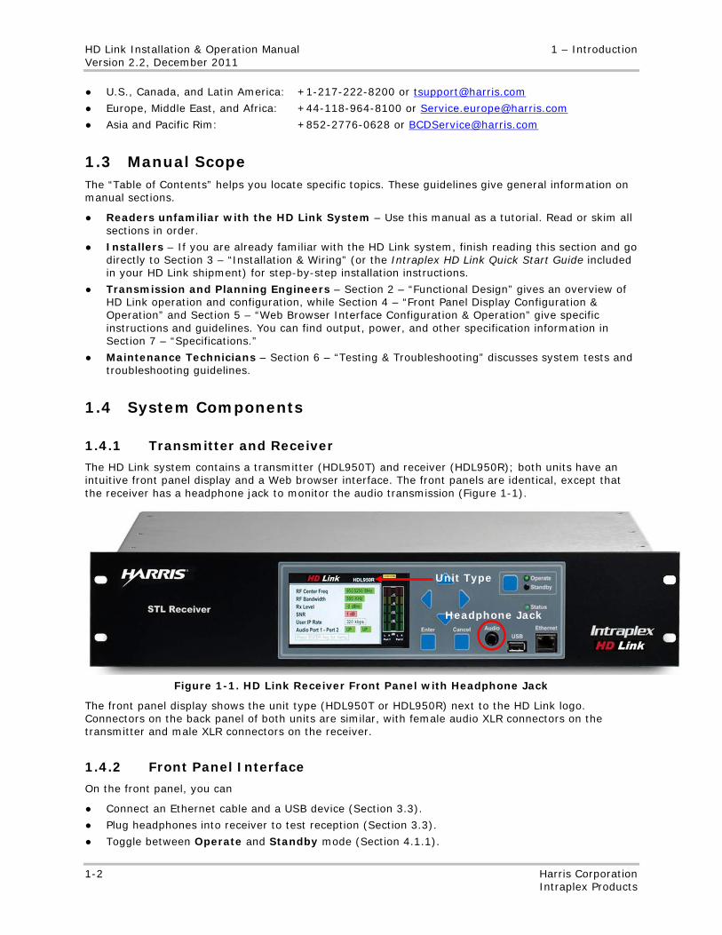
The HD Link system contains a transmitter (HDL950T) and receiver (HDL950R); both units have an intuitive front panel display and a Web browser interface. The front panels are identical, except that the receiver has a headphone jack to monitor the audio transmission (Figure 1-1).
Figure 1-1. HD Link Receiver Front Panel with Headphone Jack
The front panel display shows the unit type (HDL950T or HDL950R) next to the HD Link logo. Connectors on the back panel of both units are similar, with female audio XLR connectors on the transmitter and male XLR connectors on the receiver.
1.4.2 Front Panel Interface
On the front panel, you can
● Connect an Ethernet cable and a USB device (Section 3.3).
● Plug headphones into receiver to test reception (Section 3.3).
● Toggle between Operate and Standby mode (Section 4.1.1).
Unit Type
Headphone Jack
1 – Introduction HD Link Installation & Operation Manual Version 2.2, December 2011
Harris Corporation 1-3 Intraplex Products
● Use the front panel display (Section 4) to
• Check status information. • Configure some parameters.
1.4.3 Web Browser Interface
You can use the Web browser interface (Section 5) to remotely configure HD Link parameters, as long as you first use the front panel display to configure the initial HD port and LAN port parameters on both the transmitter and receiver (Sections 4.1.5 and 4.2). The Web browser interface shows all the status that the front panel display does.

No header here
1-4 Harris Corporation Intraplex Products
This page is left blank intentionally.
No header here
Harris Corporation 2-1 Intraplex Products
Section 2 – Functional Design
2.1 General System Description The HD Link STL (studio-to-transmitter link) is a transmitter and receiver pair that transports high quality audio using digital technology over a microwave radio path. Designed for both current analog and HD Radio®, STL applications, the HD Link system can transport multiple channels of high quality linear (uncompressed) audio or Enhanced apt-X compressed audio, along with HD Radio and other IP and Ethernet traffic.
In the U.S., FCC Rules Part 74, Subpart E, authorizes a 944-952 MHz band for over-the-air transport of audio program material. Commonly licensed bandwidths include 200, 300, and 500 kHz. The theoretical maximum amount of data carried depends on the type of modulation chosen for the link. In Canada, the 953-960 MHz band is used for the same purpose with bandwidths of 250 and 375 kHz. The HD Link system supports all these frequencies and bandwidths with a selectable radio frequency (RF) power output from 1 to 5 watts.
The HD Link digital radio uses digital quadrature amplitude modulation (QAM) with 32, 64, 128, or 256 QAM and low-density parity check (LDPC) coding type forward error correction (FEC). This modulation and advanced FEC provide very high spectral efficiency (amount of data sent over a given RF bandwidth), robustness, and high RF gain. This state-of-the-art radio technology provides the highest performance RF STL available today.
2.2 High Definition (HD) STL Development
2.2.1 Modulation
Analog 950 MHz studio-to-transmitter links transport the baseband FM composite signal. A digital STL offers significant advantages of flexibility, reliability, and quality. It can multiplex multiple user channels—such as high quality audio, data, and Ethernet traffic—over the same 950 MHz RF link. The digital component makes multiplexing seamless; there is no crosstalk or degradation between adjacent channels. A digital STL also gives errorless end-to-end data transport, unlike analog STLs, which have some degradation of the RF signal.
The quadrature amplitude modulation (QAM) scheme is widely used in digital STLs and other communication applications. In digital telecommunications, QAM data is sent as binary symbols in a grid with the number of points in the grid equaling a multiple of 2 (2, 4, 6, 8, and so on). Here are common QAM forms:
● 32 QAM
● 64 QAM
● 128 QAM
● 256 QAM
By moving to higher-order symbols or constellations, you can transmit more bits in the same RF bandwidth. In doing so, however, the mean energy between points in the QAM constellation becomes closer together and more susceptible to noise. So, a higher order QAM can deliver more data than a lower-order QAM but results in a lower signal-to-noise ratio (SNR).
In a practical QAM application, periodic pilot symbols are inserted in the payload. These pilots carry no user data and are used for enhanced phase noise immunity and improved adaptation or acquisition by the receiver. Carefully designing and optimizing the RF receiver can reduce the overhead used for pilot symbols.
When a digital 950 MHz STL carries Ethernet data to broadcast HD Radio, some problems arise. The next subsections discuss possible problems and how the HD Link system addresses and corrects them.
HD Link Installation & Operation Manual 2 – Functional Design Version 2.2, December 2011
2-2 Harris Corporation Intraplex Products
2.2.2 HD Radio Signal on an STL
The HD Radio signal depends on the location of the Importer and Exporter. Here are three scenarios:
● When the Importer and Exporter are both placed at the transmitter site, the STL needs to carry one or more audio programs as well as a low-speed data signal for the Program-Specific Data (PSD) and, if implemented, Advanced Application Services (AAS) traffic for data-only services.
● When the Importer is at the studio and the Exporter is at the transmitter site, the STL needs to transport the Importer-to-Exporter (I2E) signal, a Transmission control protocol (TCP – duplex connectivity) data signal that can run as high as 156 kbps.
● When both the Importer and Exporter are at the studio, the STL needs to carry the Exporter-to-Exgine (E2X) signal. The signal is either one-way (User Datagram Protocol – UDP) or duplex (TCP) and its bandwidth varies by the service mode in use (MP1, MP2, MP3, or MP11). With MP11 using TCP, the STL needs about 330 kbps of duplex bandwidth for E2X transport.
All three scenarios require IP data transport along with audio and—at least in some cases—duplex IP data transport.
2.2.3 Data Bandwidth Requirements
Depending on the HD component placement, the STL needs to transport up to 330 kbps of IP data traffic with one or more program audio channels. For the main analog FM broadcast program, an uncompressed linear stereo pair with 16-bit samples and 32 kHz sample rate requires just over 1 Mbps of bandwidth. When the sample rate increases to 48 kHz for 20 kHz audio, it requires 1.5 Mbps. Well-established compression algorithms, such as in the MPEG and apt-X families, can reduce these requirements considerably, but it is best to keep the STL uncompressed wherever possible to minimize chances of compromising audio quality. Adding transport of auxiliary audio channels can raise total data bandwidth requirements to over 2 Mbps.
2.2.4 STL Carrying Capacity
These basic factors affect the amount of data carried across the STL system:
● Amount of RF bandwidth available
● RF STL hardware used
● RF quality of the link
For a given RF link, a path study is conducted to determine the total required RF system gain, which factors in parameters such as
● Antenna gain.
● Cable loss.
● Transmitter power.
● Over-the-air distance.
● Fade margin.
● Required bit error rate (BER).
The RF STL hardware plays a critical role in this system gain equation.
Design and optimization of a digital RF STL is a tradeoff between spectral efficiency and BER. The difference in required signal-to-noise ratio when moving between different QAM orders is around 3 to 4 dB per step. For example, 128-QAM requires 3 to 4 dB more signal to achieve the same BER performance as 64-QAM.
There are several ways to increase a given RF link’s performance:
● Using a more powerful RF transmitter and/or higher gain antennas
● Optimizing the RF hardware circuits to
2 – Functional Design HD Link Installation & Operation Manual Version 2.2, December 2011
Harris Corporation 2-3 Intraplex Products
• Minimize circuit noise • Reject unwanted signals • Maximize receive signal sensitivity
● Adding forward error correction (FEC)
The first two ways are common to any RF system and present no special challenge in the design of a combined FM/HD transport system. FEC essentially sends additional information on the link along with the payload (audio and data) information and uses this additional information to detect data errors and rebuild any missing information at the receive end. There are several types of error correction available. However, FEC adds overhead to the total data transport requirement. When trying to compensate for poor link quality caused by using high QAM orders, and using those high QAM orders to carry more information, adding FEC can hinder the information rate gains. Therefore, the key is to use the most efficient form of FEC possible, with efficiency defined as the ability to correct the maximum amount of errors while sending the minimal amount of FEC overhead. One of the most efficient FEC schemes is low-density parity-check (LDPC) codes or turbo codes.
In information theory, the noisy-channel coding theorem (called Shannon’s theorem) establishes that, however contaminated a communicate channel is with noise interference, it is possible to communicate digital data information nearly error free up to a given maximum rate through the channel. The Shannon limit of a communications channel is the theoretical maximum information transfer rate of the channel for a particular noise level.
While LDPC and other error correcting codes cannot guarantee perfect transmission, the probability of lost information can be greatly lessened. LDPC was the first code to allow data transmission rates close to the theoretical maximum, the Shannon limit. In fact, LDPC codes can reach within 0.0045 dB of the Shannon limit.
In contrast to less efficient error correction schemes, such as Reed-Solomon, LDPC offers a clear advantage in terms of performance for a given signal-to-noise ratio. Specifically, for equal amounts of FEC overhead, LDPC requires 3 dB to 5 dB less signal for the same BER performance than does Reed-Solomon. This difference can translate to using the next-higher QAM order while maintaining the same BER and RF power level.
2.2.5 Data Quality
2.2.5.1 Network Layer
One of the core components of the HD Link system is its network layer capability, which works with data bandwidth management to determine the quality of the data information transfer. The network layer set of functionalities meets challenges of a typical STL transport application and integrates advanced data networking features, thus providing a reduction in capital and operational expense. The HD Link system contains an IP gateway architecture that support bandwidth management to efficiently prioritize and transport critical and non-critical traffic across the STL system and be able to operate in one-way as well as full-duplex link configurations.
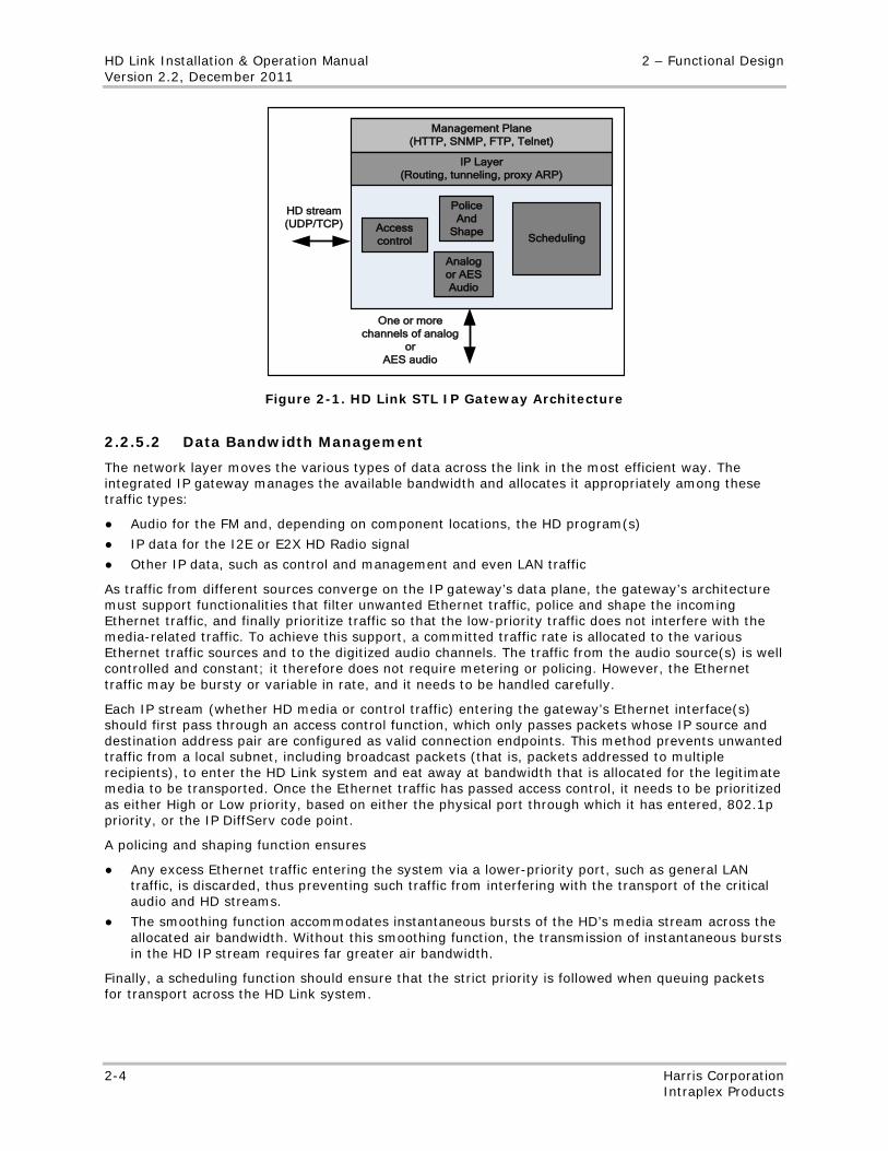
Figure 2-1 depicts a high-level view of the functionalities in the HD Link system’s IP gateway. In addition to core features, the platform manageability of this gateway contributes directly to minimizing the device’s operational cost. The system’s support of standard network management protocol functions (such as HTTP, SNMP, FTP, Telnet, and ICP) allows for more effective troubleshooting and management.
HD Link Installation & Operation Manual 2 – Functional Design Version 2.2, December 2011
2-4 Harris Corporation Intraplex Products
Accesscontrol
PoliceAnd
Shape
Analogor AESAudio
Scheduling
Management Plane (HTTP, SNMP, FTP, Telnet)
IP Layer (Routing, tunneling, proxy ARP)
HD stream (UDP/TCP)
One or more channels of analog
or AES audio
Figure 2-1. HD Link STL IP Gateway Architecture
2.2.5.2 Data Bandwidth Management
The network layer moves the various types of data across the link in the most efficient way. The integrated IP gateway manages the available bandwidth and allocates it appropriately among these traffic types:
● Audio for the FM and, depending on component locations, the HD program(s)
● IP data for the I2E or E2X HD Radio signal
● Other IP data, such as control and management and even LAN traffic
As traffic from different sources converge on the IP gateway’s data plane, the gateway’s architecture must support functionalities that filter unwanted Ethernet traffic, police and shape the incoming Ethernet traffic, and finally prioritize traffic so that the low-priority traffic does not interfere with the media-related traffic. To achieve this support, a committed traffic rate is allocated to the various Ethernet traffic sources and to the digitized audio channels. The traffic from the audio source(s) is well controlled and constant; it therefore does not require metering or policing. However, the Ethernet traffic may be bursty or variable in rate, and it needs to be handled carefully.
Each IP stream (whether HD media or control traffic) entering the gateway’s Ethernet interface(s) should first pass through an access control function, which only passes packets whose IP source and destination address pair are configured as valid connection endpoints. This method prevents unwanted traffic from a local subnet, including broadcast packets (that is, packets addressed to multiple recipients), to enter the HD Link system and eat away at bandwidth that is allocated for the legitimate media to be transported. Once the Ethernet traffic has passed access control, it needs to be prioritized as either High or Low priority, based on either the physical port through which it has entered, 802.1p priority, or the IP DiffServ code point.
A policing and shaping function ensures
● Any excess Ethernet traffic entering the system via a lower-priority port, such as general LAN traffic, is discarded, thus preventing such traffic from interfering with the transport of the critical audio and HD streams.
● The smoothing function accommodates instantaneous bursts of the HD’s media stream across the allocated air bandwidth. Without this smoothing function, the transmission of instantaneous bursts in the HD IP stream requires far greater air bandwidth.
Finally, a scheduling function should ensure that the strict priority is followed when queuing packets for transport across the HD Link system.
2 – Functional Design HD Link Installation & Operation Manual Version 2.2, December 2011
Harris Corporation 2-5 Intraplex Products
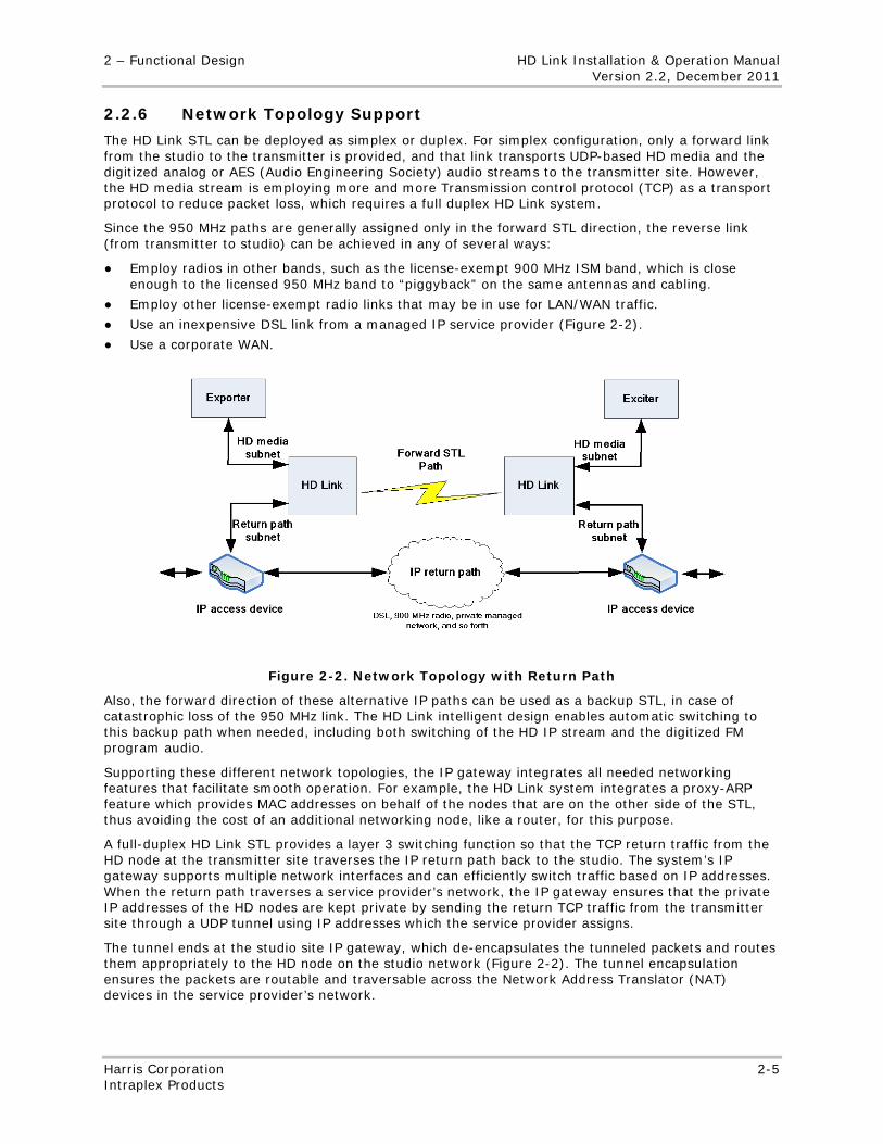
2.2.6 Network Topology Support
The HD Link STL can be deployed as simplex or duplex. For simplex configuration, only a forward link from the studio to the transmitter is provided, and that link transports UDP-based HD media and the digitized analog or AES (Audio Engineering Society) audio streams to the transmitter site. However, the HD media stream is employing more and more Transmission control protocol (TCP) as a transport protocol to reduce packet loss, which requires a full duplex HD Link system.
Since the 950 MHz paths are generally assigned only in the forward STL direction, the reverse link (from transmitter to studio) can be achieved in any of several ways:
● Employ radios in other bands, such as the license-exempt 900 MHz ISM band, which is close enough to the licensed 950 MHz band to “piggyback” on the same antennas and cabling.
● Employ other license-exempt radio links that may be in use for LAN/WAN traffic.
● Use an inexpensive DSL link from a managed IP service provider (Figure 2-2).
● Use a corporate WAN.
Figure 2-2. Network Topology with Return Path
Also, the forward direction of these alternative IP paths can be used as a backup STL, in case of catastrophic loss of the 950 MHz link. The HD Link intelligent design enables automatic switching to this backup path when needed, including both switching of the HD IP stream and the digitized FM program audio.
Supporting these different network topologies, the IP gateway integrates all needed networking features that facilitate smooth operation. For example, the HD Link system integrates a proxy-ARP feature which provides MAC addresses on behalf of the nodes that are on the other side of the STL, thus avoiding the cost of an additional networking node, like a router, for this purpose.
A full-duplex HD Link STL provides a layer 3 switching function so that the TCP return traffic from the HD node at the transmitter site traverses the IP return path back to the studio. The system’s IP gateway supports multiple network interfaces and can efficiently switch traffic based on IP addresses. When the return path traverses a service provider’s network, the IP gateway ensures that the private IP addresses of the HD nodes are kept private by sending the return TCP traffic from the transmitter site through a UDP tunnel using IP addresses which the service provider assigns.
The tunnel ends at the studio site IP gateway, which de-encapsulates the tunneled packets and routes them appropriately to the HD node on the studio network (Figure 2-2). The tunnel encapsulation ensures the packets are routable and traversable across the Network Address Translator (NAT) devices in the service provider’s network.
HD Link Installation & Operation Manual 2 – Functional Design Version 2.2, December 2011
2-6 Harris Corporation Intraplex Products
2.3 HD Link Features
2.3.1 Audio Transport
The HD Link audio transport includes
● Selectable sampling rate.
● Coding type.
● Number of channels.
Audio input can be either AES/EBU or analog. Outputs have simultaneous AES/EBU and analog. The HD Link transmitter and receiver provide two mono channels of ITU G.722 compatible audio and asynchronous auxiliary data for remote control applications. The ITU-T G.722 audio coding standard defines a method for encoding/decoding 7 kHz audio into 64 kbps. G.722 coding uses a form of sub-band adaptive differential pulse code modulation (SB-ADPCM) audio compression. The HD Link G.722 encoding/decoding offers these audio performance capabilities:
● 14 bit sample size
● 16 ksps sample rate
● 64 kbps data rate per channel
● 50 to 7000 Hz, ±1 dB audio frequency response
● Dynamic range greater than 65 dB
● Balanced input impedance of greater than 10 kOhms
● Balanced output impedance of less than 52 Ohms
● Adjustable audio input level range of between +10 and +24 dBu
● Adjustable audio output level of between 0 and +16 dBu
Channels 1 and 2 have independent settings; Channel 1 can be on while Channel 2 is off or vice versa. While not suitable for high fidelity program audio, G.722 coding is ideal for high quality voice talkback circuits and for transmission of voice-based programming such as talk shows or sports coverage.
The HD Link STL uses all these features to give top-notch, multi-channel audio performance:
● One or two stereo main program channels, each available with linear uncompressed or Enhanced apt-X compressed audio
● 32, 44.1, or 48 kHz sample rates (you select which) transporting 15, 20, or 22 kHz audio
● Two monaural, 7 kHz audio channels with G.722 coding available for AM, radio reading services, SCA, Emergency Alert System (EAS), and other auxiliary audio applications
The HD Link system supports linear encoded audio transport with an auxiliary data channel and Reed Solomon forward error correction (FEC) as the default operating mode. You can also transport linear encoded audio without an auxiliary data channel and forward error correction, thus reducing the bandwidth required for a linear stereo pair by 64 kbps.
2.3.2 Data Transport
Designed for IP data transport, the HD Link STL manages all HD Radio transport scenarios, regardless of where you place your importer and exporter. Its two prioritized Ethernet paths give preference to HD Radio data over control and other LAN/WAN data. This system supports both UDP and TCP and handles the switching of TCP return packets over asymmetric IP paths with plug-and-play simplicity. The integral TCP support provides HD Radio transport under 30 times higher bit rate error (BER). TCP return packets use IP tunneling to securely traverse third-party networks like ISPs without revealing private addresses. Layer 3 switching supports an asymmetric TCP return path for integrated “plug and play” support for TCP wherever a return path exists.
The HD Link system has an integrated IP gateway designed for transport of HD Radio-compatible IP streams. With IP prioritization, the system carries other IP data, such as control signals and LAN traffic, separately from the high-priority HD Radio stream.
2 – Functional Design HD Link Installation & Operation Manual Version 2.2, December 2011
Harris Corporation 2-7 Intraplex Products
Dual domain access control provides tight security. One access list controls HD Link units and the other access list manages the firewall to keep unwanted traffic off the transport link. An intuitive graphical front panel interface and an embedded Web server for a remote user interface provide these multiple options:
● Setup
● Control
● Monitoring
This STL system transports data through
● Integrated IP channel for HD Radio (Importer-to-Exporter or Exporter-to-Exciter).
● At least three times the nominal IP data throughput of other digital STLs.
● Suitable for use of private and public networks without requiring an external adapter to work with an external TCP return path.
● The capability to take advantage of available IP audio paths to provide integral backup in the event of radio link failure.
● Two prioritized Ethernet ports: high priority for HD Radio traffic and low priority for control data and LAN traffic.
● An RS-232 asynchronous data channel, up to 9600 bps, on each main program audio channel.
2.3.3 In-band Messaging and Synchronization
The HD Link STL system offers in-band configuration of some receive parameters to save you a trip to the tower site to configure your receiver. The transmitter uses a low-bit rate channel to send this information to the receiver at a rate of once per second:
● Audio channel parameters
• On or off • Sampling rate • Word length • Stereo or mono mode
● Auxiliary audio channel state – On or off
● LAN port IP address for return path tunneling
On the receiver, you can select whether or not to use this Service Sync functionality. If you do use it, the configuration parameters are locked on the receiver and passed from the transmitter; the parameters cannot be changed on the receiver as long as the Service Sync is enabled.
2.3.4 RF Performance
The HD Link system gives powerful, reliable RF performance with
● 1, 2, or 5 Watts RF power.
● A transmitter and receiver with 200, 250, 300, 375, or 500 kHz of RF bandwidth.
● LDPC advanced error correction – requires less receive signal than Reed-Solomon to achieve an equivalent BER, a critical parameter for glitch-free HD Radio performance.
● State-of-the-art modulation technology operating at 32, 64, 128, or 256 QAM that can provide more than 3 Mbps throughput.
● Built-in circulator so that an HD Link unit can withstand infinite VSWR at up to 25 W of power.
● High sensitivity and selectivity RF receiver circuits.
● As much as 10 dB overall system gain improvement over older digital STLs.
HD Link Installation & Operation Manual 2 – Functional Design Version 2.2, December 2011
2-8 Harris Corporation Intraplex Products
2.3.5 Setup and Operation
These features provide easy setup and reliable operation:
● Advanced Web browser user interface and SNMP remote control
● Front-panel Ethernet port to access the Web browser interface and diagnostics
● USB port to save configurations and update software
● FTP access for remote software uploads
● User-configurable control input and alarm output contacts
2.3.6 Connectors and Display
The HD Link system also offers these convenient connections and display:
● XLR AES/EBU digital and L/R analog input/output connectors
● Headphone jack on receiver for audio monitoring
● AES/EBU sync port on the receiver
● Analog level outputs for forward power and reflected power (on transmitter unit) and for received signal level and signal-to-noise (on receive unit)
● Intuitive front panel interface display with liquid crystal display (LCD) levels for all audio programs at each end
● Optional main/alternate interface for redundancy switching
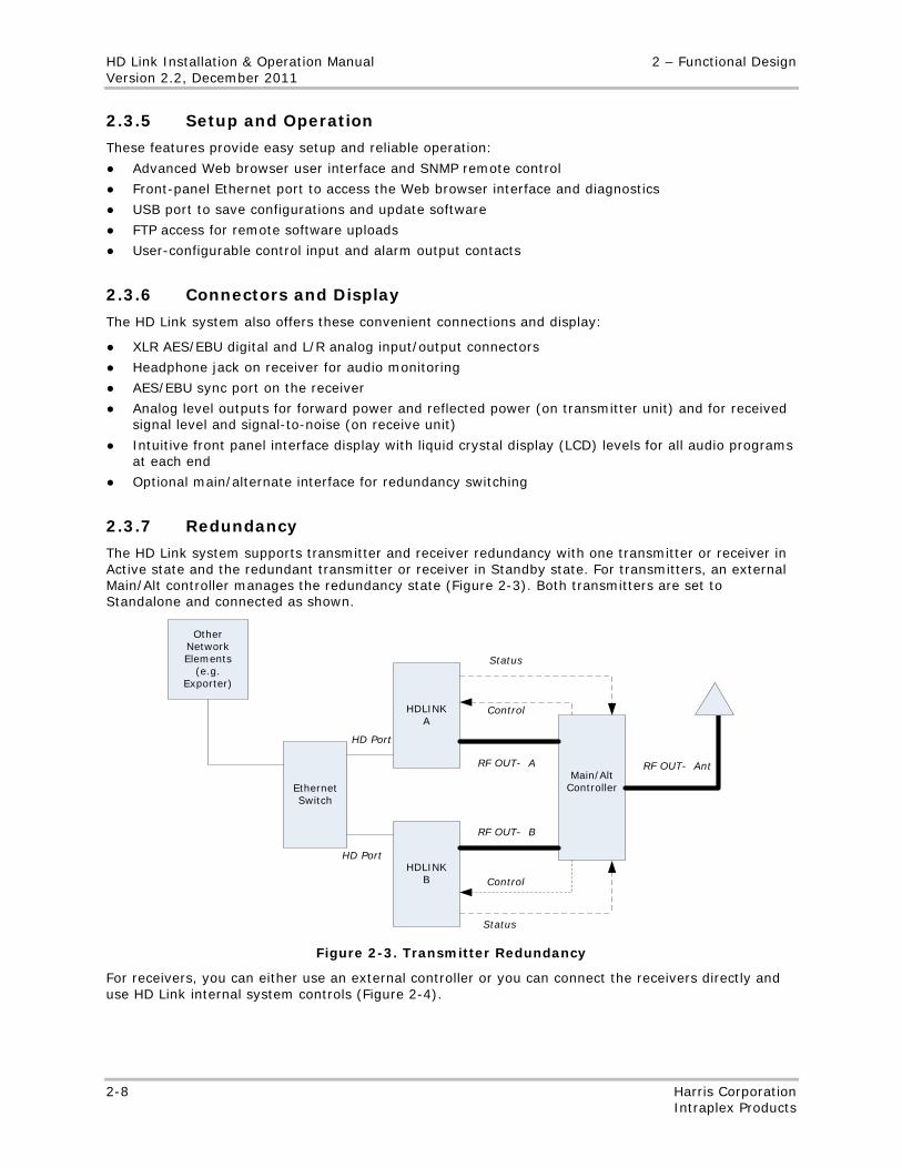
2.3.7 Redundancy
The HD Link system supports transmitter and receiver redundancy with one transmitter or receiver in Active state and the redundant transmitter or receiver in Standby state. For transmitters, an external Main/Alt controller manages the redundancy state (Figure 2-3). Both transmitters are set to Standalone and connected as shown.
HDLINK A
HDLINKB
Main/Alt ControllerEthernet
Switch
Other Network Elements
(e.g. Exporter)
HD Port
HD Port
Control
Status
Status
Control
RF OUT- A
RF OUT- B
RF OUT- Ant
Figure 2-3. Transmitter Redundancy
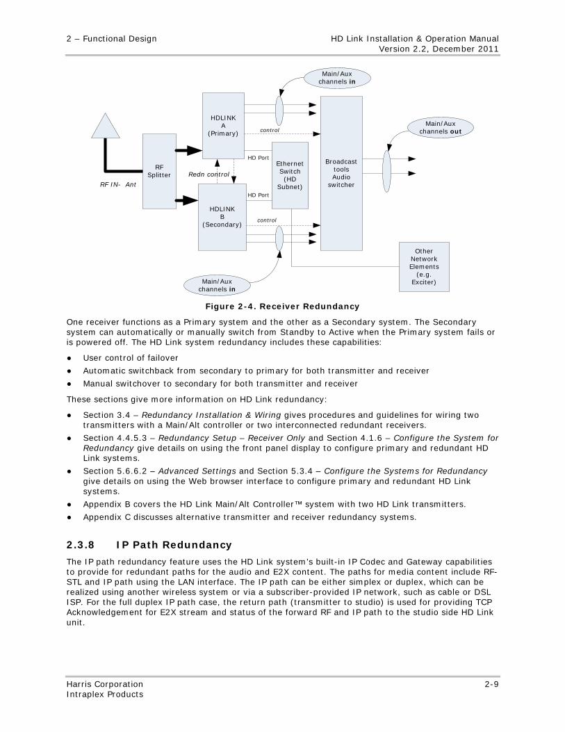
For receivers, you can either use an external controller or you can connect the receivers directly and use HD Link internal system controls (Figure 2-4).
2 – Functional Design HD Link Installation & Operation Manual Version 2.2, December 2011
Harris Corporation 2-9 Intraplex Products
HDLINK A
(Primary)
HDLINK B
(Secondary)
EthernetSwitch (HD
Subnet)
Broadcast tools Audio
switcher
Other Network Elements
(e.g. Exciter)
RF Splitter
Main/Aux channels in
control
control
HD Port
HD Port
Main/Aux channels in
Main/Aux channels out
RF IN- Ant
Redn control
Figure 2-4. Receiver Redundancy
One receiver functions as a Primary system and the other as a Secondary system. The Secondary system can automatically or manually switch from Standby to Active when the Primary system fails or is powered off. The HD Link system redundancy includes these capabilities:
● User control of failover
● Automatic switchback from secondary to primary for both transmitter and receiver
● Manual switchover to secondary for both transmitter and receiver
These sections give more information on HD Link redundancy:
● Section 3.4 – Redundancy Installation & Wiring gives procedures and guidelines for wiring two transmitters with a Main/Alt controller or two interconnected redundant receivers.
● Section 4.4.5.3 – Redundancy Setup – Receiver Only and Section 4.1.6 – Configure the System for Redundancy give details on using the front panel display to configure primary and redundant HD Link systems.
● Section 5.6.6.2 – Advanced Settings and Section 5.3.4 – Configure the Systems for Redundancy give details on using the Web browser interface to configure primary and redundant HD Link systems.
● Appendix B covers the HD Link Main/Alt Controller™ system with two HD Link transmitters.
● Appendix C discusses alternative transmitter and receiver redundancy systems.
2.3.8 IP Path Redundancy
The IP path redundancy feature uses the HD Link system’s built-in IP Codec and Gateway capabilities to provide for redundant paths for the audio and E2X content. The paths for media content include RF-STL and IP path using the LAN interface. The IP path can be either simplex or duplex, which can be realized using another wireless system or via a subscriber-provided IP network, such as cable or DSL ISP. For the full duplex IP path case, the return path (transmitter to studio) is used for providing TCP Acknowledgement for E2X stream and status of the forward RF and IP path to the studio side HD Link unit.
HD Link Installation & Operation Manual 2 – Functional Design Version 2.2, December 2011
2-10 Harris Corporation Intraplex Products
The path redundancy feature has these capabilities:
● Distributes services across both paths without any failover
● Provides asymmetric failure of the IP path by allowing simultaneous transmit of primary services with auto selection on the receiver side
● Allows the RF path to be primary and IP path to be secondary. In addition, it allows certain services on the IP path to be turned OFF when the RF path has failed so that critical services can use the IP bandwidth.
● Allows the IP path to be primary and the RF path to be secondary In addition, it allows certain services on the RF path to be turned OFF when the IP path has failed so that critical services can use the RF bandwidth.
● Allows configuration of backup service profile that can be activated when the primary path either fails or degrades With the backup service profile, you can define reduced data rate profiles for services. The backup profile is primarily used over a degraded RF path or a reduced channel capacity backup path.
The HD Link system supports these path configurations:
● RF Only – The service only uses the forward STL path.
● IP Only – The service only uses the forward IP path. This setting can be used in combination with the RF Only setting for load balancing over multiple paths without failover capability.
● RF Failover to IP – The service uses RF as the primary path and IP as the backup path. This setting indicates that the service should fail over to the IP path when the RF path fails.
● IP Failover to RF – The service uses IP as the primary path and RF as the backup path. This setting indicates that the service should fail over to the RF path when the IP path fails.
● IP, Drop If RF Fails– This setting, applicable when RF is the primary path and IP is the backup path, indicates that the service uses the IP path only if the RF path has not failed. IF the RF path fails, the service ceases to operate. This setting is generally used for low priority (non-critical) services, when other higher priority services are set to RF Failover to IP. The IP if RF is OK setting allows for low priority services to operate on the IP path until the RF path fails. When the RF path fails, the low priority services are turned OFF so that the higher priority (critical) services can use the available IP bandwidth.
● RF, Drop If IP Fails – This setting, applicable when IP is the primary path and RF is the backup path, indicates that the service only uses the RF path and only if the IP path has not failed. IF the IP path fails, the service ceases to operate. This setting allows for non-critical services to be turned OFF during a failure so that the critical services can use the backup RF-STL bandwidth. Take care when using this setting, as the RF path’s modem parameter is dynamically set based on the required information rate. The services getting stopped due to this setting should be higher in capacity than the higher priority services that will take over their capacity. Generally, when using the IP path as the primary and a reduced RF path as a backup, it is safer to use a separate backup profile which becomes active when the services switch to the RF path. When this setting is used, the system performs the necessary check to assure the entire backup profile fits on the RF path.
● RF and IP – Content is continually sent over both the RF and IP paths to the receiver. The receiver automatically selects the path, thereby allowing for scenarios where the failover time is critical and the forward path status cannot be reliably sent to the studio side of the HD Link system. This setting provides the least interruption (almost inaudible) in services during a path failure. However, the setting does require that the backup path capacity is always needed for the service.
2.3.8.1 IP Path Network Models
The IP path redundancy feature also supports redundancy of individual E2X IP streams to support an Exporter failover scenario, thus allowing redundant pair Exporters to simultaneously stream UDP E2X streams to the same Exciter, with the HD Link system performing the IP switching to ensure that only one E2X stream is delivered to the Exciter. Figure 2-5 shows the scenario where the IP Path is full
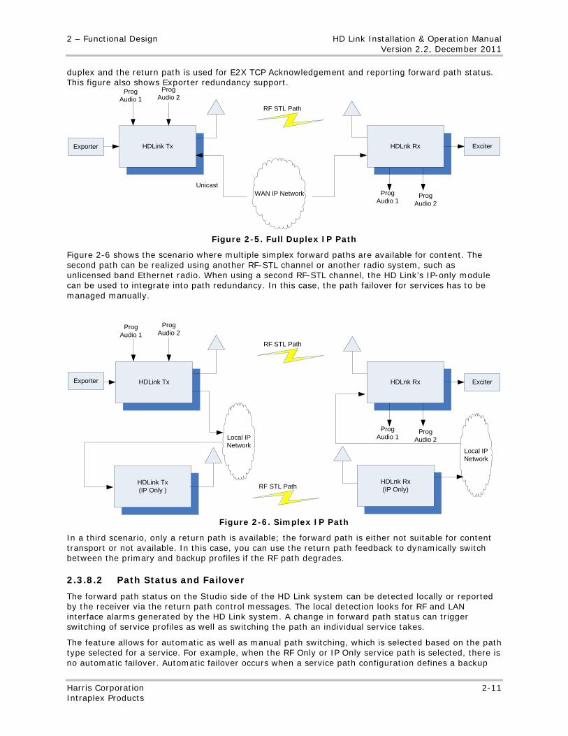
2 – Functional Design HD Link Installation & Operation Manual Version 2.2, December 2011
Harris Corporation 2-11 Intraplex Products
duplex and the return path is used for E2X TCP Acknowledgement and reporting forward path status. This figure also shows Exporter redundancy support.
HDLink Tx
WAN IP Network
HDLnk Rx
ProgAudio 1
ProgAudio 2
ProgAudio 1
ProgAudio 2
RF STL Path
Exporter Exciter
Unicast
Figure 2-5. Full Duplex IP Path
Figure 2-6 shows the scenario where multiple simplex forward paths are available for content. The second path can be realized using another RF-STL channel or another radio system, such as unlicensed band Ethernet radio. When using a second RF-STL channel, the HD Link’s IP-only module can be used to integrate into path redundancy. In this case, the path failover for services has to be managed manually.
HDLink Tx
Local IP Network
HDLnk Rx
HDLnk Rx(IP Only)
HDLink Tx (IP Only )
ProgAudio 1
ProgAudio 2
ProgAudio 1
ProgAudio 2
RF STL Path
Exporter Exciter
Local IP Network
RF STL Path
Figure 2-6. Simplex IP Path
In a third scenario, only a return path is available; the forward path is either not suitable for content transport or not available. In this case, you can use the return path feedback to dynamically switch between the primary and backup profiles if the RF path degrades.
2.3.8.2 Path Status and Failover
The forward path status on the Studio side of the HD Link system can be detected locally or reported by the receiver via the return path control messages. The local detection looks for RF and LAN interface alarms generated by the HD Link system. A change in forward path status can trigger switching of service profiles as well as switching the path an individual service takes.
The feature allows for automatic as well as manual path switching, which is selected based on the path type selected for a service. For example, when the RF Only or IP Only service path is selected, there is no automatic failover. Automatic failover occurs when a service path configuration defines a backup
HD Link Installation & Operation Manual 2 – Functional Design Version 2.2, December 2011
2-12 Harris Corporation Intraplex Products
path, such as the RF Failover to IP path defines RF as the primary path and IP as the backup path. The internal logic switches the service’s path based on the status of its primary path.
In addition to path switching for services, the IP path redundancy feature also lets you configure a backup profile to which the system can switch in the event of path degradation or failure. The backup profile allows you to change the audio source rate as well as turn off channels, in order to reduce the overall bit rate. Coupled with the service path selection, the backup profile lets you control how a particular service operates under any given condition.
When automatic failover is disabled, you can perform manual switching of a service path from RF Only to IP Only or (or IP Only to RF Only) based on the current service path status. Path remapping can be done at run time and takes effect immediately.
2.3.8.3 Reversion
With reversion control, you can set whether the feature automatically reverts back to the primary service path once the status is restored. This control provides configurable hysteresis for the path status to be declared operational. When reversion is disabled, you can use the Path Switchback command to manually switch back to the primary path.
2.3.8.4 Backup Profile’s Automatic Audio Quality Adjustment
Due to the available bandwidth of the backup path, you might need to scale the quality of the audio services down to reduce the required bit rate. You can define these parameters for each main audio channel when operating over the backup path:
● Sampling rate (32, 44, 48 Khz) based on the install audio cards
● Word length (16, 20, 24 bits) based on the install audio cards
When a given service is operating on the backup path, the audio parameters are applied and synchronized automatically at both ends of the link.
2.3.8.5 IP Path Jitter Mitigation
The packet delay variation caused by network jitter can vary based on the quality of the IP network. To account for variability in network jitter, the path redundancy feature provides a configurable jitter buffer for the audio services.
2.3.8.6 Configuration and Status
You can configure this feature and view status on the Path Redundancy page in the HD Link Web browser interface. (Section 5.6.6.3 gives more information.) You can also configure the backup profile on the Program Services page. The audio channels change when the system switches to the backup path. (Section 5.6.4 gives information on configuring both the main and backup profiles.) You can also view path redundancy status on the front panel display (Section 4.4.4.10).
2.3.9 Software-based STL Repeater
The HD Link system now uses an STL repeater application to increase the RF range and link of the program audio carrying the STL path from the STL (transmitter) to the end-most STL (receiver). Figure 2-7 shows the HD Link software-based repeater configuration.
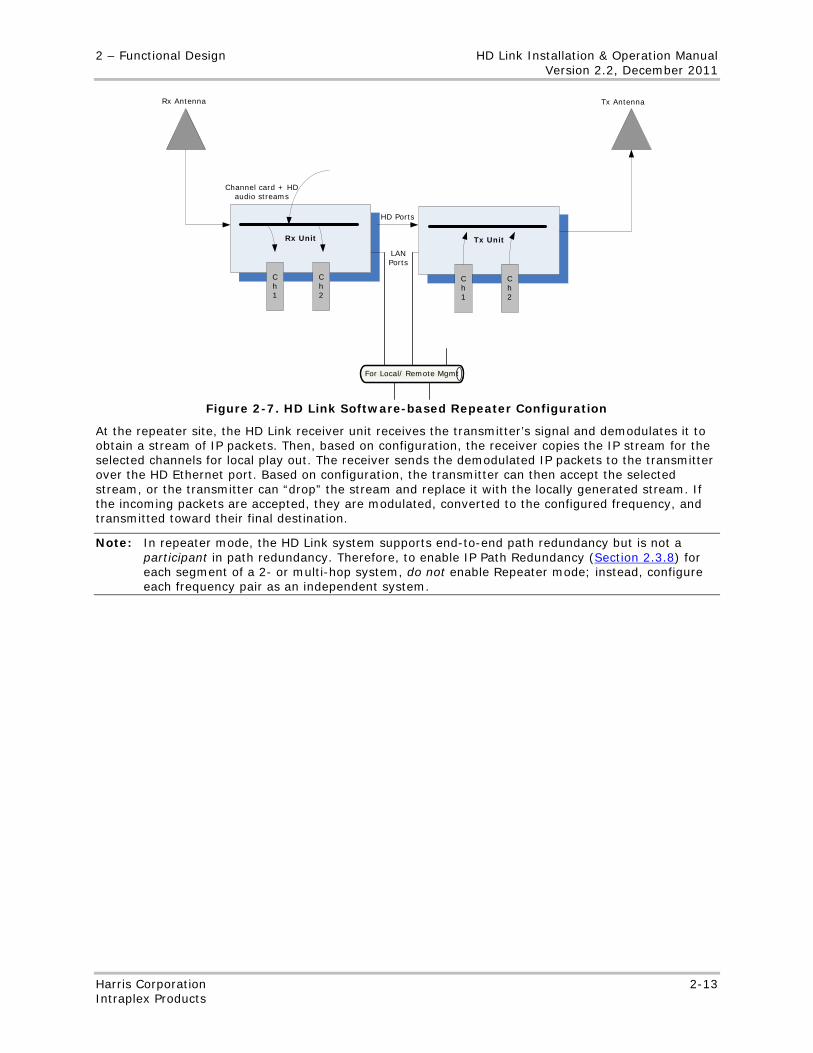
2 – Functional Design HD Link Installation & Operation Manual Version 2.2, December 2011
Harris Corporation 2-13 Intraplex Products
Rx Unit
Ch 1
Ch 2
For Local/ Remote Mgmt
Tx Unit
Ch 1
Ch 2
HD Ports
LAN Ports
Rx Antenna Tx Antenna
Channel card + HD audio streams
Figure 2-7. HD Link Software-based Repeater Configuration
At the repeater site, the HD Link receiver unit receives the transmitter’s signal and demodulates it to obtain a stream of IP packets. Then, based on configuration, the receiver copies the IP stream for the selected channels for local play out. The receiver sends the demodulated IP packets to the transmitter over the HD Ethernet port. Based on configuration, the transmitter can then accept the selected stream, or the transmitter can “drop” the stream and replace it with the locally generated stream. If the incoming packets are accepted, they are modulated, converted to the configured frequency, and transmitted toward their final destination.
Note: In repeater mode, the HD Link system supports end-to-end path redundancy but is not a participant in path redundancy. Therefore, to enable IP Path Redundancy (Section 2.3.8) for each segment of a 2- or multi-hop system, do not enable Repeater mode; instead, configure each frequency pair as an independent system.

No header here
2-14 Harris Corporation Intraplex Products
This page is left blank intentionally.
3-1 Harris Corporation Intraplex Products
Section 3 – Installation
This section describes installation procedures and guidelines for the Intraplex HD Link transmitter and receiver and covers these topics:
● Tools and cable requirements
● Equipment unpacking and inspection
● Transmitter and receiver installation
● Wiring and external connections
● Unit powering
3.1 Installation Preparation
3.1.1 Tools and Cables Required
In addition to the equipment provided with your HD Link system, we recommend these items to complete the system installation:
● Basic telecommunications installation tool kit (such as screwdrivers and wire stripper)
● Rack mounting hardware (four threaded bolts per shelf)
● Power, audio, and data cables
3.1.2 Equipment Unpacking and Inspection
Upon receipt of your HD Link system, complete these tasks:
1. Inspect all shipping containers for damage. If you observe damage, notify the shipping service as soon as possible.
2. Unpack all equipment from containers.
3. Inspect equipment for damage.
4. Verify that the HD Link transmitter and receiver are equipped as expected, confirming items from the packing list (Bill of Materials):
• Chassis with rack mount in good condition • Power supply, cables, and utilities
If you have questions regarding possible equipment damage or shipping errors, contact Harris Customer Service:
● U.S., Canada, and Latin America: +1-217-222-8200 or [email protected] ● Europe, Middle East, and Africa: +44-118-964-8100 or [email protected] ● Asia and Pacific Rim: +852-2776-0628 or [email protected]
Warning! Follow your company’s rules regarding AC powered equipment installation. If there is a conflict between any procedure in this document and your company's safety rules, your company’s safety rules must take priority.
3.2 Transmitter and Receiver Installation The transmitter and receiver equipment shelves in your shipment are shipped assembled and pre-configured. If applicable, bolt the shelf into the designated equipment rack. If either the HD Link
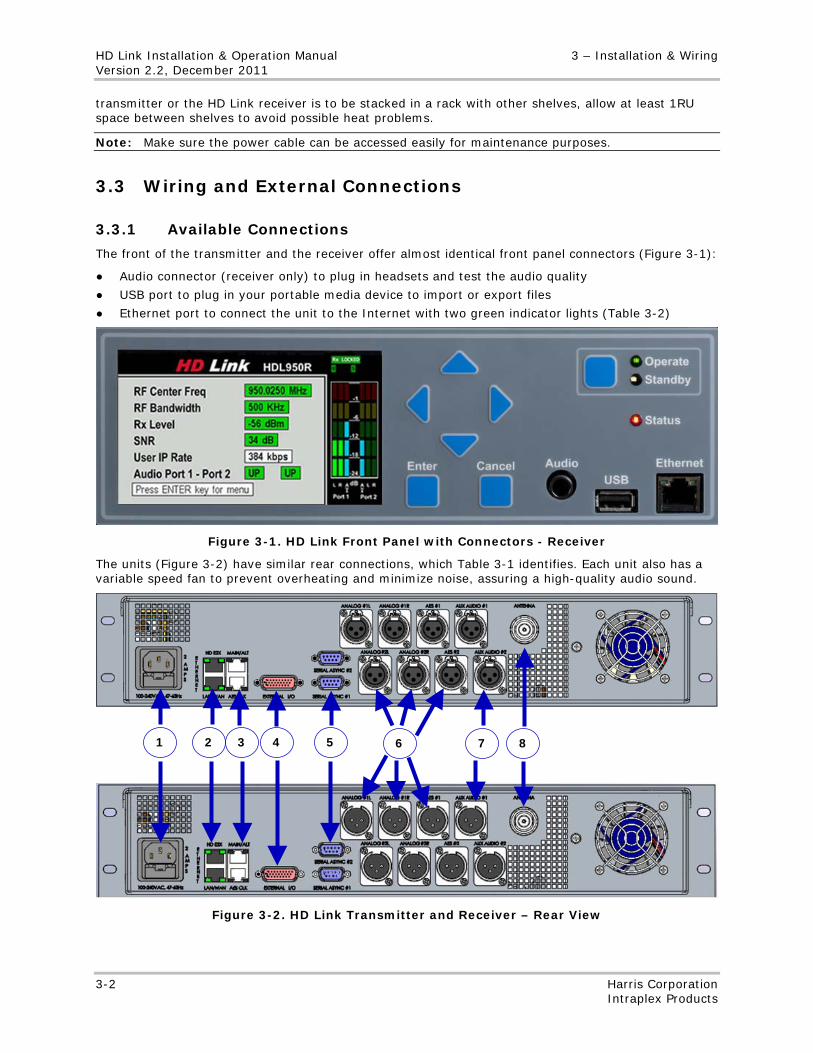
HD Link Installation & Operation Manual 3 – Installation & Wiring Version 2.2, December 2011
3-2 Harris Corporation Intraplex Products
transmitter or the HD Link receiver is to be stacked in a rack with other shelves, allow at least 1RU space between shelves to avoid possible heat problems.
Note: Make sure the power cable can be accessed easily for maintenance purposes.
3.3 Wiring and External Connections
3.3.1 Available Connections
The front of the transmitter and the receiver offer almost identical front panel connectors (Figure 3-1):
● Audio connector (receiver only) to plug in headsets and test the audio quality
● USB port to plug in your portable media device to import or export files
● Ethernet port to connect the unit to the Internet with two green indicator lights (Table 3-2)
Figure 3-1. HD Link Front Panel with Connectors - Receiver
The units (Figure 3-2) have similar rear connections, which Table 3-1 identifies. Each unit also has a variable speed fan to prevent overheating and minimize noise, assuring a high-quality audio sound.
Figure 3-2. HD Link Transmitter and Receiver – Rear View
4 2 5 6 1 3 7 8
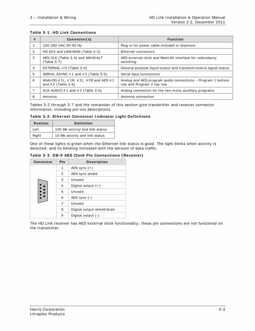
3 – Installation & Wiring HD Link Installation & Operation Manual Version 2.2, December 2011
Harris Corporation 3-3 Intraplex Products
Table 3-1. HD Link Connections
# Connector(s) Function
1 100-260 VAC 50-60 Hz Plug-in for power cable included in shipment
2 HD E2X and LAN/WAN (Table 3-2) Ethernet connectors
3 AES CLK (Table 3-3) and MAIN/ALT (Table 3-7)
AES external clock and Main/Alt interface for redundancy switching
4 EXTERNAL I/O (Table 3-4) General purpose input/output and transmit/receive signal status
5 SERIAL ASYNC #1 and #2 (Table 3-5) Serial data connections
6 ANALOG #1L, #1R, #2L, #2R and AES #1 and #2 (Table 3-6)
Analog and AES program audio connections – Program 1 bottom row and Program 2 top row
7 AUX AUDIO #1 and #2 (Table 3-6) Analog connection for the two mono auxiliary programs
8 Antenna Antenna connection
Tables 3-2 through 3-7 and the remainder of this section give transmitter and receiver connector information, including pin-out descriptions.
Table 3-2. Ethernet Connector Indicator Light Definitions
Position Definition
Left 100 Mb activity and link status
Right 10 Mb activity and link status
One of these lights is green when the Ethernet link status is good. The light blinks when activity is detected, and its blinking increases with the amount of data traffic.
Table 3-3. DB-9 AES Clock Pin Connections (Receiver)
Connector Pin Description
1 AES sync (+)
2 AES sync shield
3 Unused
4 Digital output (+)
5 Unused
6 AES sync (-)
7 Unused
8 Digital output shield/drain
9 Digital output (-)
The HD Link receiver has AES external clock functionality; these pin connections are not functional on the transmitter.
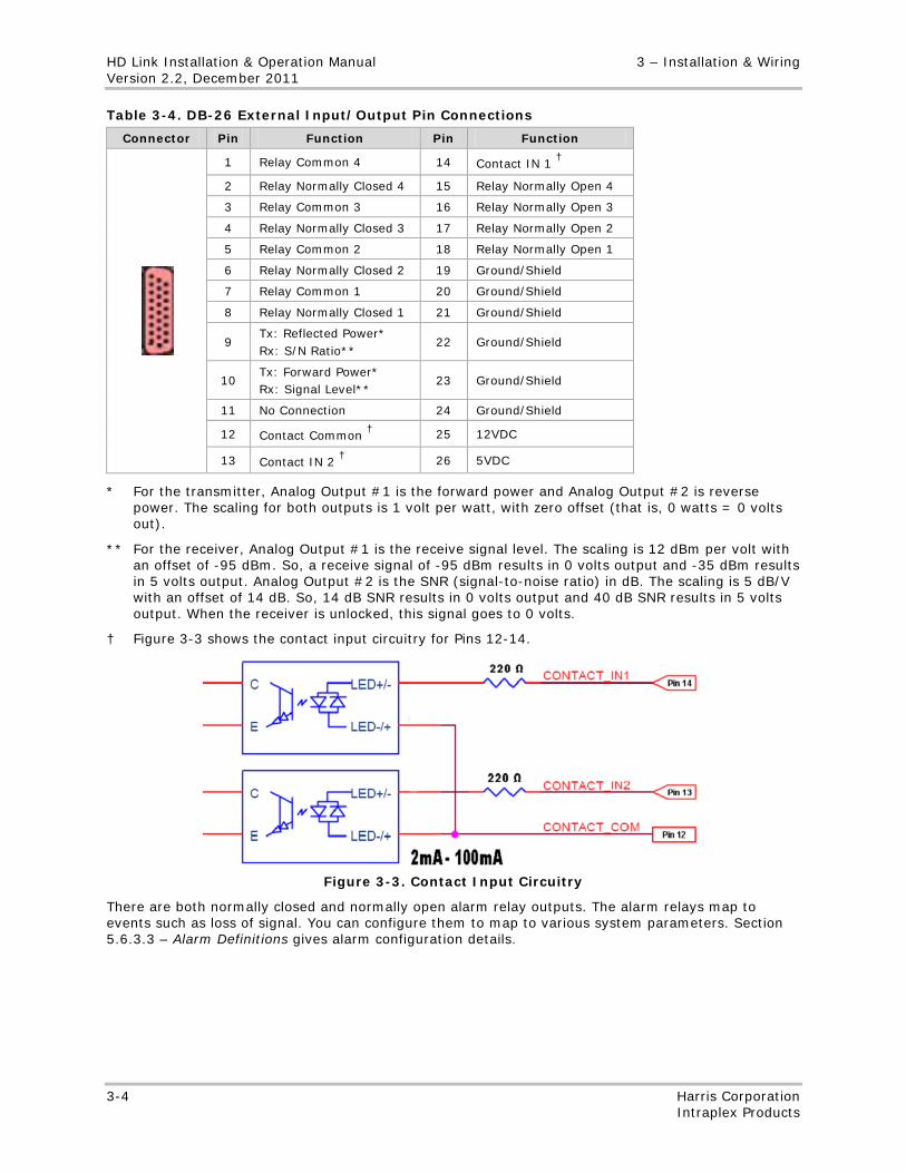
HD Link Installation & Operation Manual 3 – Installation & Wiring Version 2.2, December 2011
3-4 Harris Corporation Intraplex Products
Table 3-4. DB-26 External Input/Output Pin Connections
Connector Pin Function Pin Function
1 Relay Common 4 14 Contact IN 1 †
2 Relay Normally Closed 4 15 Relay Normally Open 4
3 Relay Common 3 16 Relay Normally Open 3
4 Relay Normally Closed 3 17 Relay Normally Open 2
5 Relay Common 2 18 Relay Normally Open 1
6 Relay Normally Closed 2 19 Ground/Shield
7 Relay Common 1 20 Ground/Shield
8 Relay Normally Closed 1 21 Ground/Shield
9 Tx: Reflected Power* Rx: S/N Ratio**
22 Ground/Shield
10 Tx: Forward Power* Rx: Signal Level**
23 Ground/Shield
11 No Connection 24 Ground/Shield
12 Contact Common † 25 12VDC
13 Contact IN 2 † 26 5VDC
* For the transmitter, Analog Output #1 is the forward power and Analog Output #2 is reverse power. The scaling for both outputs is 1 volt per watt, with zero offset (that is, 0 watts = 0 volts out).
** For the receiver, Analog Output #1 is the receive signal level. The scaling is 12 dBm per volt with an offset of -95 dBm. So, a receive signal of -95 dBm results in 0 volts output and -35 dBm results in 5 volts output. Analog Output #2 is the SNR (signal-to-noise ratio) in dB. The scaling is 5 dB/V with an offset of 14 dB. So, 14 dB SNR results in 0 volts output and 40 dB SNR results in 5 volts output. When the receiver is unlocked, this signal goes to 0 volts.
† Figure 3-3 shows the contact input circuitry for Pins 12-14.
Figure 3-3. Contact Input Circuitry
There are both normally closed and normally open alarm relay outputs. The alarm relays map to events such as loss of signal. You can configure them to map to various system parameters. Section 5.6.3.3 – Alarm Definitions gives alarm configuration details.
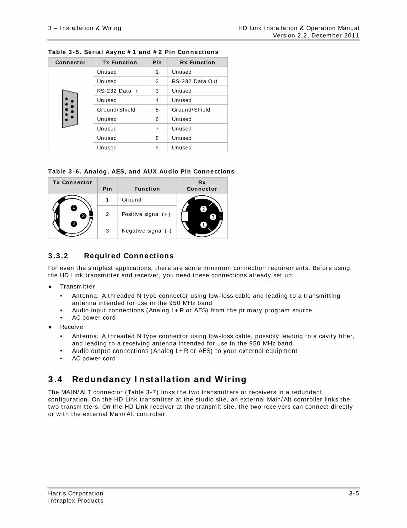
3 – Installation & Wiring HD Link Installation & Operation Manual Version 2.2, December 2011
Harris Corporation 3-5 Intraplex Products
Table 3-5. Serial Async #1 and #2 Pin Connections
Connector Tx Function Pin Rx Function
Unused 1 Unused
Unused 2 RS-232 Data Out
RS-232 Data In 3 Unused
Unused 4 Unused
Ground/Shield 5 Ground/Shield
Unused 6 Unused
Unused 7 Unused
Unused 8 Unused
Unused 9 Unused
Table 3-6. Analog, AES, and AUX Audio Pin Connections
Tx Connector Pin Function
Rx Connector
1 Ground
2 Positive signal (+)
3 Negative signal (-)
3.3.2 Required Connections
For even the simplest applications, there are some minimum connection requirements. Before using the HD Link transmitter and receiver, you need these connections already set up:
● Transmitter
• Antenna: A threaded N type connector using low-loss cable and leading to a transmitting antenna intended for use in the 950 MHz band
• Audio input connections (Analog L+R or AES) from the primary program source • AC power cord
● Receiver
• Antenna: A threaded N type connector using low-loss cable, possibly leading to a cavity filter, and leading to a receiving antenna intended for use in the 950 MHz band
• Audio output connections (Analog L+R or AES) to your external equipment • AC power cord
3.4 Redundancy Installation and Wiring The MAIN/ALT connector (Table 3-7) links the two transmitters or receivers in a redundant configuration. On the HD Link transmitter at the studio site, an external Main/Alt controller links the two transmitters. On the HD Link receiver at the transmit site, the two receivers can connect directly or with the external Main/Alt controller.
1
3
2
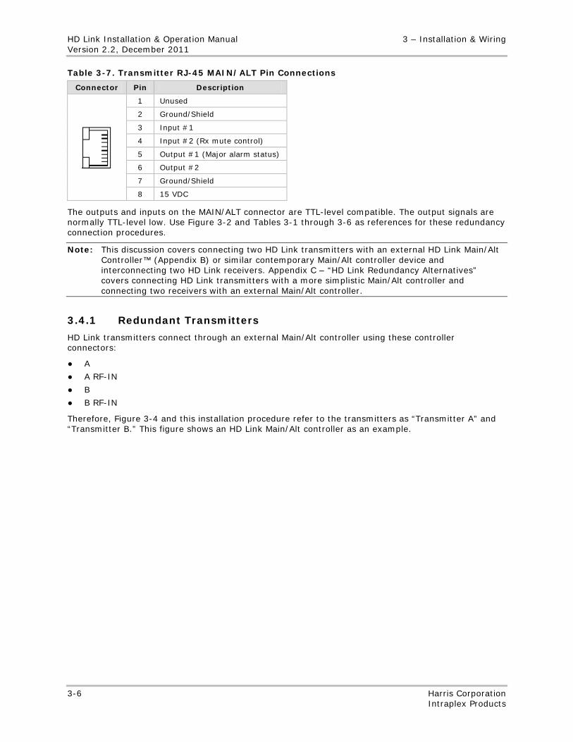
HD Link Installation & Operation Manual 3 – Installation & Wiring Version 2.2, December 2011
3-6 Harris Corporation Intraplex Products
Table 3-7. Transmitter RJ-45 MAIN/ALT Pin Connections
Connector Pin Description
1 Unused
2 Ground/Shield
3 Input #1
4 Input #2 (Rx mute control)
5 Output #1 (Major alarm status)
6 Output #2
7 Ground/Shield
8 15 VDC
The outputs and inputs on the MAIN/ALT connector are TTL-level compatible. The output signals are normally TTL-level low. Use Figure 3-2 and Tables 3-1 through 3-6 as references for these redundancy connection procedures.
Note: This discussion covers connecting two HD Link transmitters with an external HD Link Main/Alt Controller™ (Appendix B) or similar contemporary Main/Alt controller device and interconnecting two HD Link receivers. Appendix C – “HD Link Redundancy Alternatives” covers connecting HD Link transmitters with a more simplistic Main/Alt controller and connecting two receivers with an external Main/Alt controller.
3.4.1 Redundant Transmitters
HD Link transmitters connect through an external Main/Alt controller using these controller connectors:
● A
● A RF-IN
● B
● B RF-IN
Therefore, Figure 3-4 and this installation procedure refer to the transmitters as “Transmitter A” and “Transmitter B.” This figure shows an HD Link Main/Alt controller as an example.
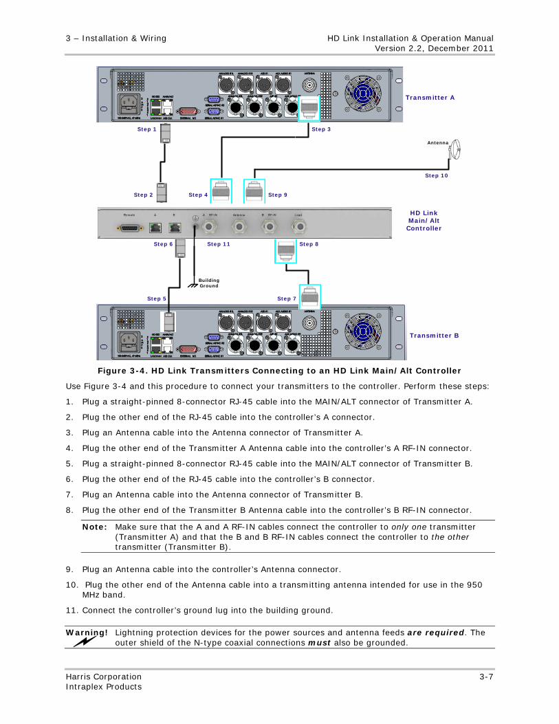
3 – Installation & Wiring HD Link Installation & Operation Manual Version 2.2, December 2011
Harris Corporation 3-7 Intraplex Products
Step 1
Step 2
Step 3
Step 4
Step 5
Step 6
Step 7
Step 8
Step 9
Step 11
Step 10
Antenna
Building Ground
Transmitter A
Transmitter B
HD Link Main/Alt Controller
Figure 3-4. HD Link Transmitters Connecting to an HD Link Main/Alt Controller
Use Figure 3-4 and this procedure to connect your transmitters to the controller. Perform these steps:
1. Plug a straight-pinned 8-connector RJ-45 cable into the MAIN/ALT connector of Transmitter A.
2. Plug the other end of the RJ-45 cable into the controller’s A connector.
3. Plug an Antenna cable into the Antenna connector of Transmitter A.
4. Plug the other end of the Transmitter A Antenna cable into the controller’s A RF-IN connector.
5. Plug a straight-pinned 8-connector RJ-45 cable into the MAIN/ALT connector of Transmitter B.
6. Plug the other end of the RJ-45 cable into the controller’s B connector.
7. Plug an Antenna cable into the Antenna connector of Transmitter B.
8. Plug the other end of the Transmitter B Antenna cable into the controller’s B RF-IN connector.
Note: Make sure that the A and A RF-IN cables connect the controller to only one transmitter (Transmitter A) and that the B and B RF-IN cables connect the controller to the other transmitter (Transmitter B).
9. Plug an Antenna cable into the controller’s Antenna connector.
10. Plug the other end of the Antenna cable into a transmitting antenna intended for use in the 950 MHz band.
11. Connect the controller’s ground lug into the building ground.
Warning! Lightning protection devices for the power sources and antenna feeds are required. The outer shield of the N-type coaxial connections must also be grounded.
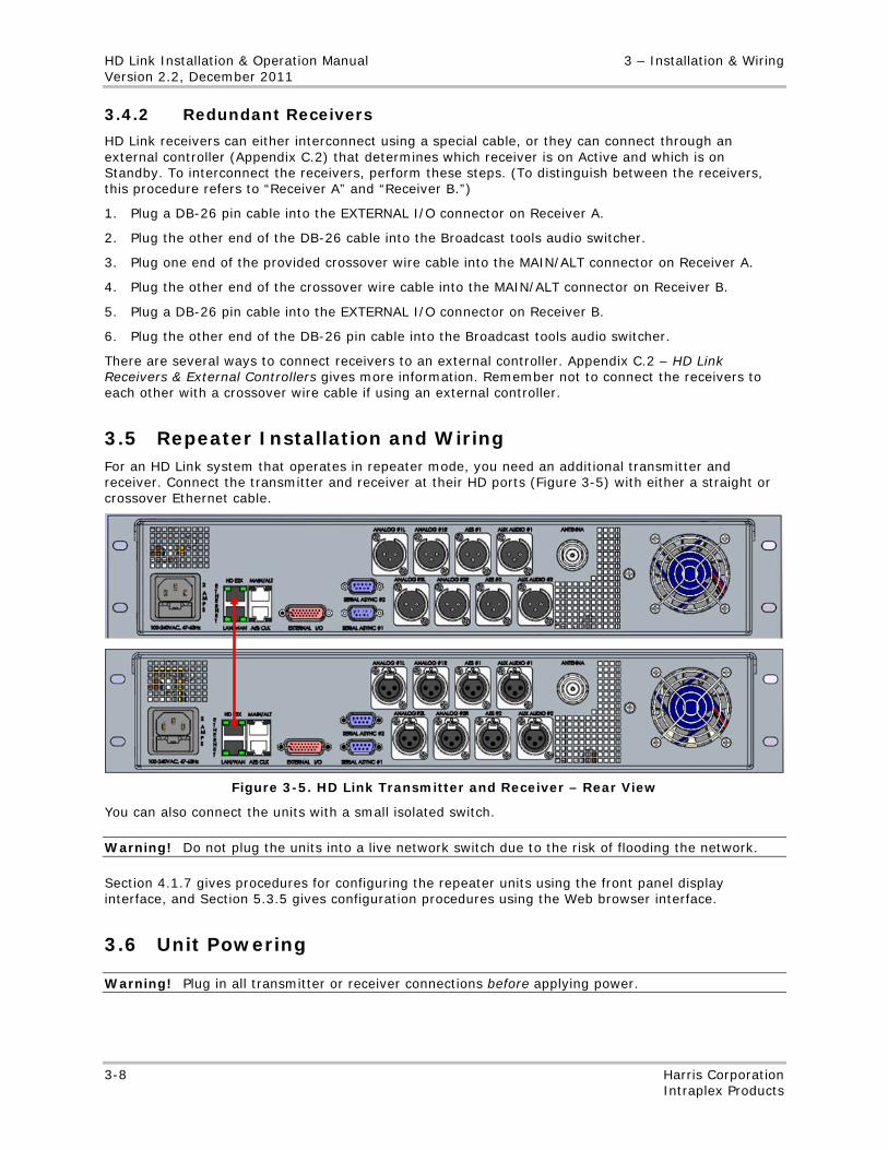
HD Link Installation & Operation Manual 3 – Installation & Wiring Version 2.2, December 2011
3-8 Harris Corporation Intraplex Products
3.4.2 Redundant Receivers
HD Link receivers can either interconnect using a special cable, or they can connect through an external controller (Appendix C.2) that determines which receiver is on Active and which is on Standby. To interconnect the receivers, perform these steps. (To distinguish between the receivers, this procedure refers to “Receiver A” and “Receiver B.”)
1. Plug a DB-26 pin cable into the EXTERNAL I/O connector on Receiver A.
2. Plug the other end of the DB-26 cable into the Broadcast tools audio switcher.
3. Plug one end of the provided crossover wire cable into the MAIN/ALT connector on Receiver A.
4. Plug the other end of the crossover wire cable into the MAIN/ALT connector on Receiver B.
5. Plug a DB-26 pin cable into the EXTERNAL I/O connector on Receiver B.
6. Plug the other end of the DB-26 pin cable into the Broadcast tools audio switcher.
There are several ways to connect receivers to an external controller. Appendix C.2 – HD Link Receivers & External Controllers gives more information. Remember not to connect the receivers to each other with a crossover wire cable if using an external controller.
3.5 Repeater Installation and Wiring For an HD Link system that operates in repeater mode, you need an additional transmitter and receiver. Connect the transmitter and receiver at their HD ports (Figure 3-5) with either a straight or crossover Ethernet cable.
Figure 3-5. HD Link Transmitter and Receiver – Rear View
You can also connect the units with a small isolated switch.
Warning! Do not plug the units into a live network switch due to the risk of flooding the network.
Section 4.1.7 gives procedures for configuring the repeater units using the front panel display interface, and Section 5.3.5 gives configuration procedures using the Web browser interface.
3.6 Unit Powering
Warning! Plug in all transmitter or receiver connections before applying power.
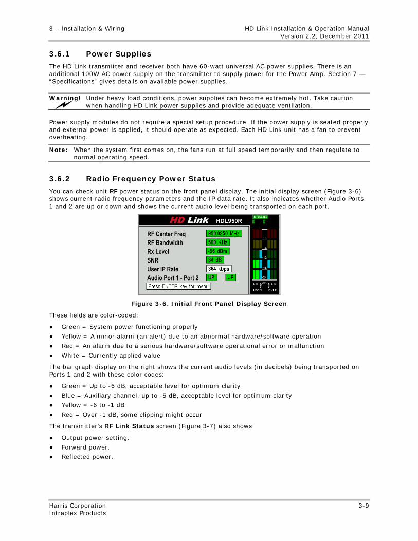
3 – Installation & Wiring HD Link Installation & Operation Manual Version 2.2, December 2011
Harris Corporation 3-9 Intraplex Products
3.6.1 Power Supplies
The HD Link transmitter and receiver both have 60-watt universal AC power supplies. There is an additional 100W AC power supply on the transmitter to supply power for the Power Amp. Section 7 — “Specifications” gives details on available power supplies.
Warning! Under heavy load conditions, power supplies can become extremely hot. Take caution when handling HD Link power supplies and provide adequate ventilation.
Power supply modules do not require a special setup procedure. If the power supply is seated properly and external power is applied, it should operate as expected. Each HD Link unit has a fan to prevent overheating.
Note: When the system first comes on, the fans run at full speed temporarily and then regulate to normal operating speed.
3.6.2 Radio Frequency Power Status
You can check unit RF power status on the front panel display. The initial display screen (Figure 3-6) shows current radio frequency parameters and the IP data rate. It also indicates whether Audio Ports 1 and 2 are up or down and shows the current audio level being transported on each port.
Figure 3-6. Initial Front Panel Display Screen
These fields are color-coded:
● Green = System power functioning properly
● Yellow = A minor alarm (an alert) due to an abnormal hardware/software operation
● Red = An alarm due to a serious hardware/software operational error or malfunction
● White = Currently applied value
The bar graph display on the right shows the current audio levels (in decibels) being transported on Ports 1 and 2 with these color codes:
● Green = Up to -6 dB, acceptable level for optimum clarity
● Blue = Auxiliary channel, up to -5 dB, acceptable level for optimum clarity
● Yellow = -6 to -1 dB
● Red = Over -1 dB, some clipping might occur
The transmitter’s RF Link Status screen (Figure 3-7) also shows
● Output power setting.
● Forward power.
● Reflected power.
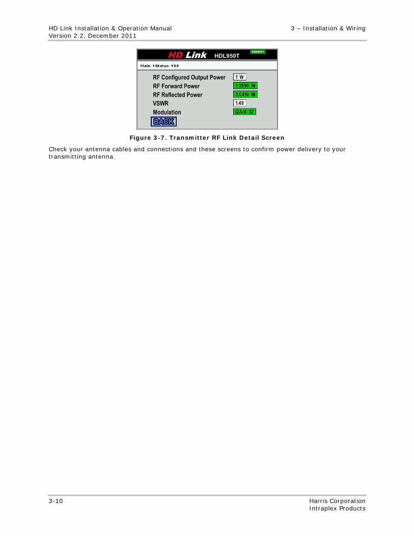
HD Link Installation & Operation Manual 3 – Installation & Wiring Version 2.2, December 2011
3-10 Harris Corporation Intraplex Products
Figure 3-7. Transmitter RF Link Detail Screen
Check your antenna cables and connections and these screens to confirm power delivery to your transmitting antenna.
No header
Harris Corporation 4-1 Intraplex Products
Section 4 – Front Panel Configuration & Operation On the HD Link front panel display, you can access status information and make some configuration changes. This section gives you configuration and operation information for the front panel display:
● Procedures for configuring the HD Link system initially, including configuring
• Network interface parameters • RF profile • Service profile
● Basic operation guidelines
● Upgrade procedure
● Front panel field descriptions and operation instructions, including
• Screen graphics • Field descriptions • Navigation guides
The front panel screens have color-coded fields. Here are the color code definitions:
● Green
• Power on • No errors • Successful operation (such as successfully saving or deleting a file)
● Yellow
• Power on standby • Alert (minor error/alarm) • Value changed on screen but not saved or applied • Test in progress
● Red
• Power off • Major error/alarm
● White
• Currently applied value • No test in progress
These definitions vary slightly depending on the specific fields. Not all screens are color-coded. Some field descriptions in this section include color-code definitions.
Note: When you change a value for a white field, the field becomes yellow, alerting you that the value has neither been saved nor applied.
For details on each screen, go to Section 4.4 – Front Panel Buttons & Screens. For information on panel buttons and how to navigate between screens, go to Section 4.4.1 – Panel Buttons & Screen Navigation.
The system also provides a Web browser interface (covered in Section 5 – “Web Browser Interface Configuration & Operation”) in which you can access status information and make configuration changes. The front panel screens are similar to the Web browser interface pages.
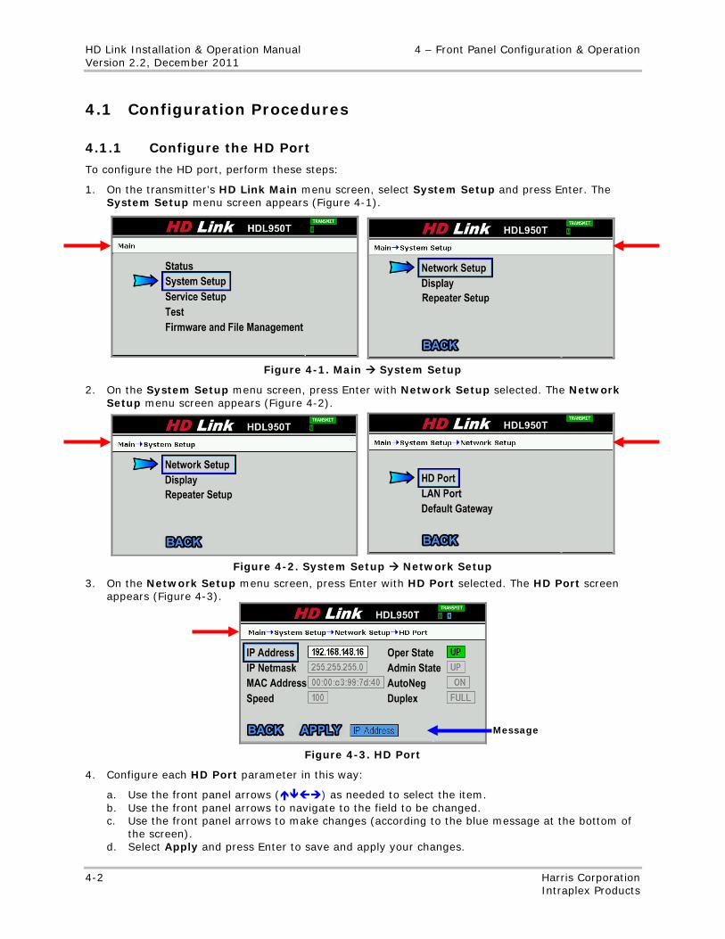
HD Link Installation & Operation Manual 4 – Front Panel Configuration & Operation Version 2.2, December 2011
4-2 Harris Corporation Intraplex Products
4.1 Configuration Procedures
4.1.1 Configure the HD Port
To configure the HD port, perform these steps:
1. On the transmitter’s HD Link Main menu screen, select System Setup and press Enter. The System Setup menu screen appears (Figure 4-1).
Figure 4-1. Main System Setup
2. On the System Setup menu screen, press Enter with Network Setup selected. The Network Setup menu screen appears (Figure 4-2).
Figure 4-2. System Setup Network Setup
3. On the Network Setup menu screen, press Enter with HD Port selected. The HD Port screen appears (Figure 4-3).
Figure 4-3. HD Port
4. Configure each HD Port parameter in this way:
a. Use the front panel arrows () as needed to select the item. b. Use the front panel arrows to navigate to the field to be changed. c. Use the front panel arrows to make changes (according to the blue message at the bottom of
the screen). d. Select Apply and press Enter to save and apply your changes.
Message

4 – Front Panel Configuration & Operation HD Link Installation & Operation Manual Version 2.2, December 2011
Harris Corporation 4-3 Intraplex Products
e. Press Cancel to return to the Network Setup page without saving changes. f. To return to the System Setup menu, select Back or press Cancel.
5. Perform the previous steps on the receiver to configure its HD port.
4.1.2 Configure the LAN Port
To configure the LAN port, perform these steps:
1. On the transmitter’s Network Setup front panel menu page, select LAN Port and press Enter. The LAN Port screen appears (Figure 4-4).
Figure 4-4. LAN Port
2. Configure each LAN Port parameter in this way:
a. Use the front panel arrows () as needed to select the item. b. Use the front panel arrows to navigate to the field to be changed. c. Use the front panel arrows to make changes (according to the blue message at the bottom of
the screen). d. Select Apply and press Enter to save and apply your changes. e. Press Cancel to return to the Network Setup page without saving changes. f. To return to the System Setup menu, select Back or press Cancel.
3. Perform the previous steps on the receiver to configure its LAN port.
4.1.3 Configure the RF Profile Parameters
To configure the RF profile center frequency and/or bandwidth parameters, perform these steps:
1. On the HD Link Main menu screen, select Service Setup and press Enter. The Service Setup menu screen appears (Figure 4-5).
Figure 4-5. Main Service Setup
2. On the Service Setup menu screen, press Enter with RF Profile selected. The RF Profile screen appears (Figure 4-6).
Message
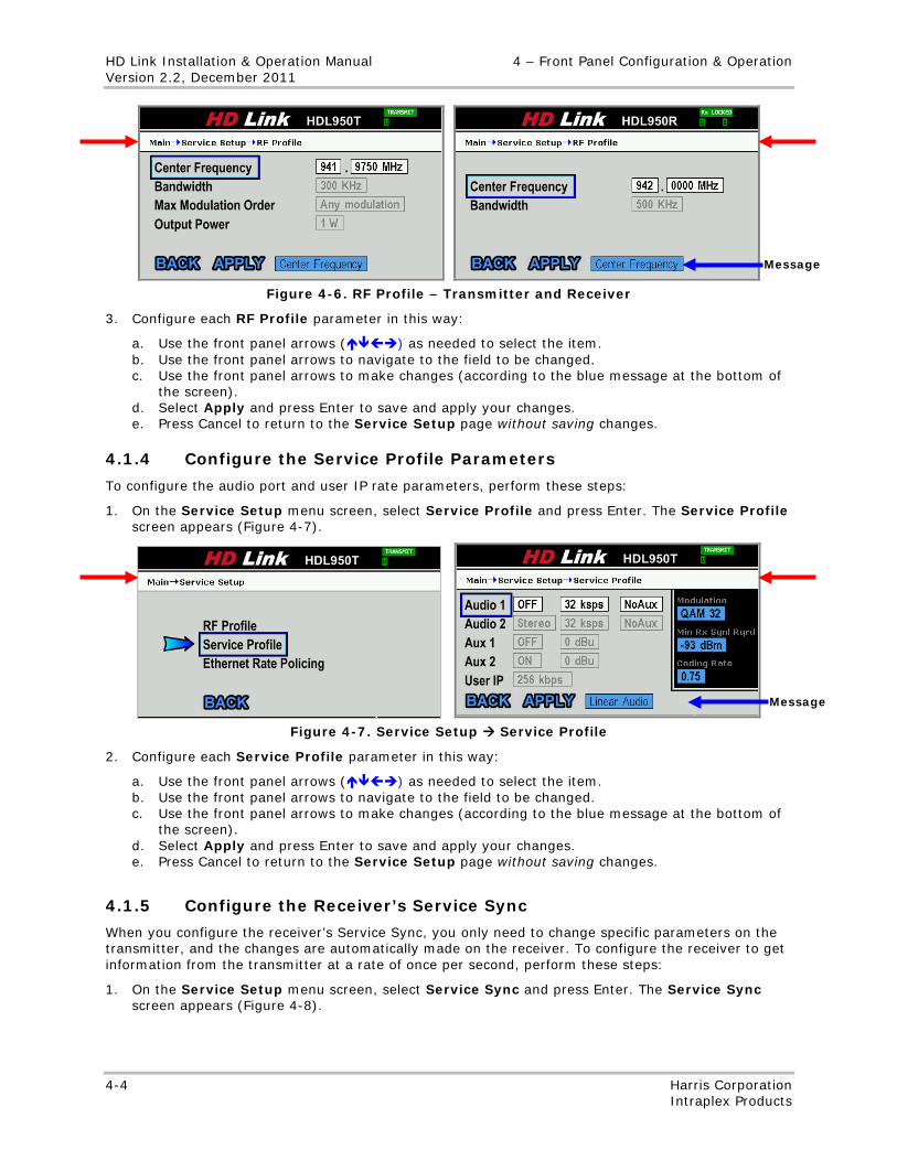
HD Link Installation & Operation Manual 4 – Front Panel Configuration & Operation Version 2.2, December 2011
4-4 Harris Corporation Intraplex Products
Figure 4-6. RF Profile – Transmitter and Receiver
3. Configure each RF Profile parameter in this way:
a. Use the front panel arrows () as needed to select the item. b. Use the front panel arrows to navigate to the field to be changed. c. Use the front panel arrows to make changes (according to the blue message at the bottom of
the screen). d. Select Apply and press Enter to save and apply your changes. e. Press Cancel to return to the Service Setup page without saving changes.
4.1.4 Configure the Service Profile Parameters
To configure the audio port and user IP rate parameters, perform these steps:
1. On the Service Setup menu screen, select Service Profile and press Enter. The Service Profile screen appears (Figure 4-7).
Figure 4-7. Service Setup Service Profile
2. Configure each Service Profile parameter in this way:
a. Use the front panel arrows () as needed to select the item. b. Use the front panel arrows to navigate to the field to be changed. c. Use the front panel arrows to make changes (according to the blue message at the bottom of
the screen). d. Select Apply and press Enter to save and apply your changes. e. Press Cancel to return to the Service Setup page without saving changes.
4.1.5 Configure the Receiver’s Service Sync
When you configure the receiver’s Service Sync, you only need to change specific parameters on the transmitter, and the changes are automatically made on the receiver. To configure the receiver to get information from the transmitter at a rate of once per second, perform these steps:
1. On the Service Setup menu screen, select Service Sync and press Enter. The Service Sync screen appears (Figure 4-8).
Message
Message
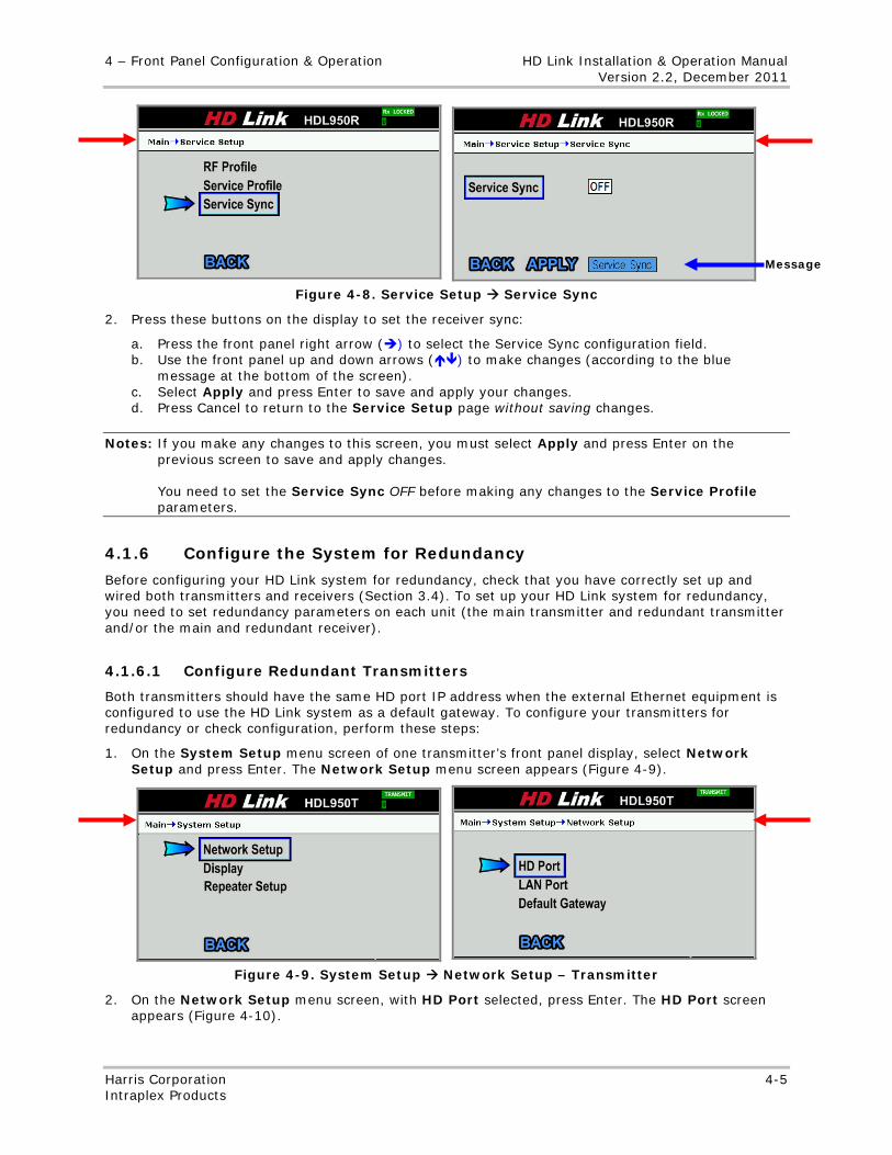
4 – Front Panel Configuration & Operation HD Link Installation & Operation Manual Version 2.2, December 2011
Harris Corporation 4-5 Intraplex Products
Figure 4-8. Service Setup Service Sync
2. Press these buttons on the display to set the receiver sync:
a. Press the front panel right arrow () to select the Service Sync configuration field. b. Use the front panel up and down arrows () to make changes (according to the blue
message at the bottom of the screen). c. Select Apply and press Enter to save and apply your changes. d. Press Cancel to return to the Service Setup page without saving changes.
Notes: If you make any changes to this screen, you must select Apply and press Enter on the previous screen to save and apply changes. You need to set the Service Sync OFF before making any changes to the Service Profile parameters.
4.1.6 Configure the System for Redundancy
Before configuring your HD Link system for redundancy, check that you have correctly set up and wired both transmitters and receivers (Section 3.4). To set up your HD Link system for redundancy, you need to set redundancy parameters on each unit (the main transmitter and redundant transmitter and/or the main and redundant receiver).
4.1.6.1 Configure Redundant Transmitters
Both transmitters should have the same HD port IP address when the external Ethernet equipment is configured to use the HD Link system as a default gateway. To configure your transmitters for redundancy or check configuration, perform these steps:
1. On the System Setup menu screen of one transmitter’s front panel display, select Network Setup and press Enter. The Network Setup menu screen appears (Figure 4-9).
Figure 4-9. System Setup Network Setup – Transmitter
2. On the Network Setup menu screen, with HD Port selected, press Enter. The HD Port screen appears (Figure 4-10).
Message
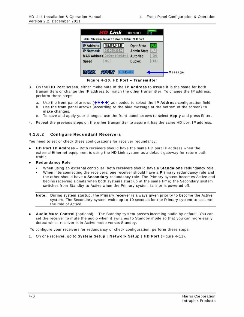
HD Link Installation & Operation Manual 4 – Front Panel Configuration & Operation Version 2.2, December 2011
4-6 Harris Corporation Intraplex Products
Figure 4-10. HD Port – Transmitter
3. On the HD Port screen, either make note of the IP Address to assure it is the same for both transmitters or change the IP address to match the other transmitter. To change the IP address, perform these steps:
a. Use the front panel arrows () as needed to select the IP Address configuration field. b. Use the front panel arrows (according to the blue message at the bottom of the screen) to
make changes. c. To save and apply your changes, use the front panel arrows to select Apply and press Enter.
4. Repeat the previous steps on the other transmitter to assure it has the same HD port IP address.
4.1.6.2 Configure Redundant Receivers
You need to set or check these configurations for receiver redundancy:
● HD Port IP Address – Both receivers should have the same HD port IP address when the external Ethernet equipment is using the HD Link system as a default gateway for return path traffic.
● Redundancy Role
• When using an external controller, both receivers should have a Standalone redundancy role. • When interconnecting the receivers, one receiver should have a Primary redundancy role and
the other should have a Secondary redundancy role. The Primary system becomes Active and begins receiving signals when both systems start up at the same time; the Secondary system switches from Standby to Active when the Primary system fails or is powered off.
Note: During system startup, the Primary receiver is always given priority to become the Active system. The Secondary system waits up to 10 seconds for the Primary system to assume the role of Active.
● Audio Mute Control (optional) – The Standby system passes incoming audio by default. You can set the receiver to mute the audio when it switches to Standby mode so that you can more easily detect which receiver is in Active mode versus Standby.
To configure your receivers for redundancy or check configuration, perform these steps:
1. On one receiver, go to System Setup | Network Setup | HD Port (Figure 4-11).
Message
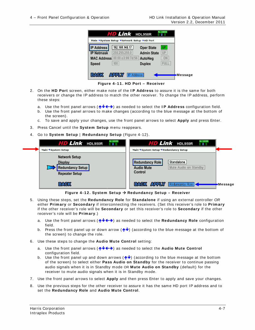
4 – Front Panel Configuration & Operation HD Link Installation & Operation Manual Version 2.2, December 2011
Harris Corporation 4-7 Intraplex Products
Figure 4-11. HD Port – Receiver
2. On the HD Port screen, either make note of the IP Address to assure it is the same for both receivers or change the IP address to match the other receiver. To change the IP address, perform these steps:
a. Use the front panel arrows () as needed to select the IP Address configuration field. b. Use the front panel arrows to make changes (according to the blue message at the bottom of
the screen). c. To save and apply your changes, use the front panel arrows to select Apply and press Enter.
3. Press Cancel until the System Setup menu reappears.
4. Go to System Setup | Redundancy Setup (Figure 4-12).
Figure 4-12. System Setup Redundancy Setup – Receiver
5. Using these steps, set the Redundancy Role for Standalone if using an external controller OR either Primary or Secondary if interconnecting the receivers. (Set this receiver’s role to Primary if the other receiver’s role will be Secondary or set this receiver’s role to Secondary if the other receiver’s role will be Primary.)
a. Use the front panel arrows () as needed to select the Redundancy Role configuration field.
b. Press the front panel up or down arrow () (according to the blue message at the bottom of the screen) to change the role.
6. Use these steps to change the Audio Mute Control setting:
a. Use the front panel arrows () as needed to select the Audio Mute Control configuration field.
b. Use the front panel up and down arrows () (according to the blue message at the bottom of the screen) to select either Pass Audio on Standby for the receiver to continue passing audio signals when it is in Standby mode OR Mute Audio on Standby (default) for the receiver to mute audio signals when it is in Standby mode.
7. Use the front panel arrows to select Apply and then press Enter to apply and save your changes.
8. Use the previous steps for the other receiver to assure it has the same HD port IP address and to set the Redundancy Role and Audio Mute Control.
Message
Message
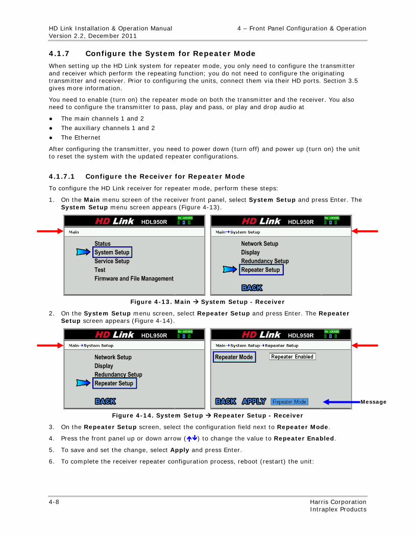
HD Link Installation & Operation Manual 4 – Front Panel Configuration & Operation Version 2.2, December 2011
4-8 Harris Corporation Intraplex Products
4.1.7 Configure the System for Repeater Mode
When setting up the HD Link system for repeater mode, you only need to configure the transmitter and receiver which perform the repeating function; you do not need to configure the originating transmitter and receiver. Prior to configuring the units, connect them via their HD ports. Section 3.5 gives more information.
You need to enable (turn on) the repeater mode on both the transmitter and the receiver. You also need to configure the transmitter to pass, play and pass, or play and drop audio at
● The main channels 1 and 2
● The auxiliary channels 1 and 2
● The Ethernet
After configuring the transmitter, you need to power down (turn off) and power up (turn on) the unit to reset the system with the updated repeater configurations.
4.1.7.1 Configure the Receiver for Repeater Mode
To configure the HD Link receiver for repeater mode, perform these steps:
1. On the Main menu screen of the receiver front panel, select System Setup and press Enter. The System Setup menu screen appears (Figure 4-13).
Figure 4-13. Main System Setup - Receiver
2. On the System Setup menu screen, select Repeater Setup and press Enter. The Repeater Setup screen appears (Figure 4-14).
Figure 4-14. System Setup Repeater Setup - Receiver
3. On the Repeater Setup screen, select the configuration field next to Repeater Mode.
4. Press the front panel up or down arrow () to change the value to Repeater Enabled.
5. To save and set the change, select Apply and press Enter.
6. To complete the receiver repeater configuration process, reboot (restart) the unit:
Message
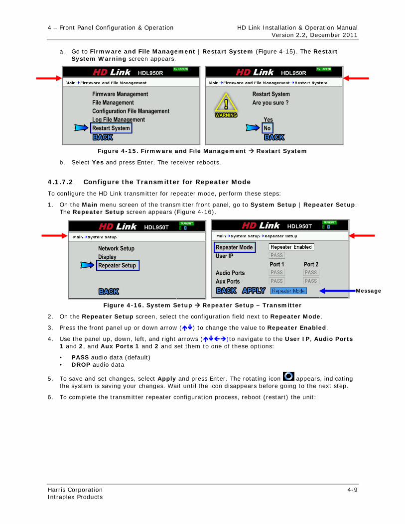
4 – Front Panel Configuration & Operation HD Link Installation & Operation Manual Version 2.2, December 2011
Harris Corporation 4-9 Intraplex Products
a. Go to Firmware and File Management | Restart System (Figure 4-15). The Restart System Warning screen appears.
Figure 4-15. Firmware and File Management Restart System
b. Select Yes and press Enter. The receiver reboots.
4.1.7.2 Configure the Transmitter for Repeater Mode
To configure the HD Link transmitter for repeater mode, perform these steps:
1. On the Main menu screen of the transmitter front panel, go to System Setup | Repeater Setup. The Repeater Setup screen appears (Figure 4-16).
Figure 4-16. System Setup Repeater Setup – Transmitter
2. On the Repeater Setup screen, select the configuration field next to Repeater Mode.
3. Press the front panel up or down arrow () to change the value to Repeater Enabled.
4. Use the panel up, down, left, and right arrows ()to navigate to the User IP, Audio Ports 1 and 2, and Aux Ports 1 and 2 and set them to one of these options:
• PASS audio data (default) • DROP audio data
5. To save and set changes, select Apply and press Enter. The rotating icon appears, indicating the system is saving your changes. Wait until the icon disappears before going to the next step.
6. To complete the transmitter repeater configuration process, reboot (restart) the unit:
Message
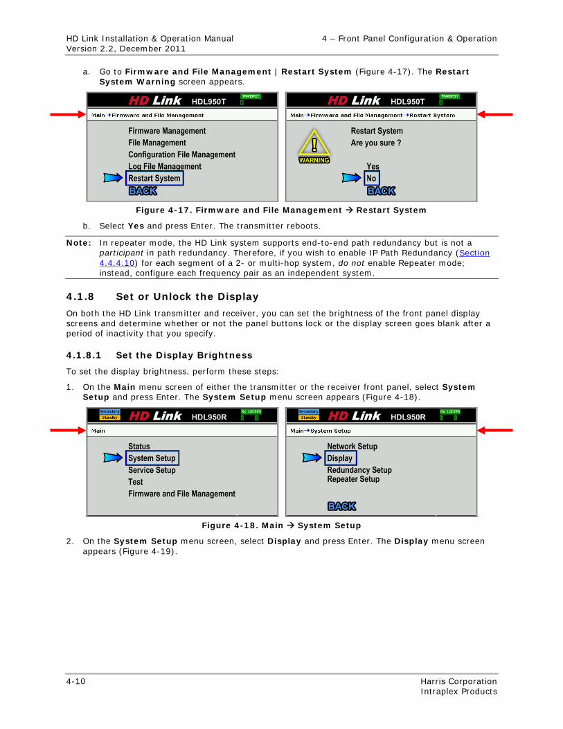
HD Link Installation & Operation Manual 4 – Front Panel Configuration & Operation Version 2.2, December 2011
4-10 Harris Corporation Intraplex Products
a. Go to Firmware and File Management | Restart System (Figure 4-17). The Restart System Warning screen appears.
Figure 4-17. Firmware and File Management Restart System
b. Select Yes and press Enter. The transmitter reboots.
Note: In repeater mode, the HD Link system supports end-to-end path redundancy but is not a participant in path redundancy. Therefore, if you wish to enable IP Path Redundancy (Section 4.4.4.10) for each segment of a 2- or multi-hop system, do not enable Repeater mode; instead, configure each frequency pair as an independent system.
4.1.8 Set or Unlock the Display
On both the HD Link transmitter and receiver, you can set the brightness of the front panel display screens and determine whether or not the panel buttons lock or the display screen goes blank after a period of inactivity that you specify.
4.1.8.1 Set the Display Brightness
To set the display brightness, perform these steps:
1. On the Main menu screen of either the transmitter or the receiver front panel, select System Setup and press Enter. The System Setup menu screen appears (Figure 4-18).
Figure 4-18. Main System Setup
2. On the System Setup menu screen, select Display and press Enter. The Display menu screen appears (Figure 4-19).
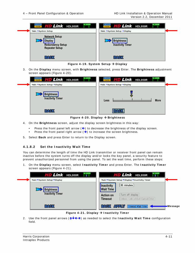
4 – Front Panel Configuration & Operation HD Link Installation & Operation Manual Version 2.2, December 2011
Harris Corporation 4-11 Intraplex Products
Figure 4-19. System Setup Display
3. On the Display menu screen, with Brightness selected, press Enter. The Brightness adjustment screen appears (Figure 4-20).
Figure 4-20. Display Brightness
4. On the Brightness screen, adjust the display screen brightness in this way:
• Press the front panel left arrow () to decrease the brightness of the display screen. • Press the front panel right arrow () to increase the screen brightness.
5. Select Back and press Enter to return to the Display screen.
4.1.8.2 Set the Inactivity Wait Time
You can determine the length of time the HD Link transmitter or receiver front panel can remain inactive before the system turns off the display and/or locks the key panel, a security feature to prevent unauthorized personnel from using the panel. To set the wait time, perform these steps:
1. On the Display menu screen, select Inactivity Timer and press Enter. The Inactivity Timer screen appears (Figure 4-21).
Figure 4-21. Display Inactivity Timer
2. Use the front panel arrows () as needed to select the Inactivity Wait Time configuration field.
Message
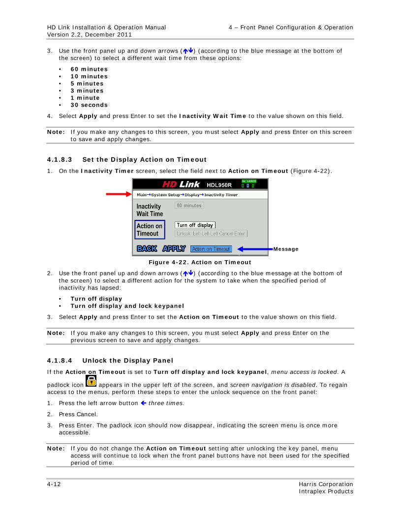
HD Link Installation & Operation Manual 4 – Front Panel Configuration & Operation Version 2.2, December 2011
4-12 Harris Corporation Intraplex Products
3. Use the front panel up and down arrows () (according to the blue message at the bottom of the screen) to select a different wait time from these options:
• 60 minutes • 10 minutes • 5 minutes • 3 minutes • 1 minute • 30 seconds
4. Select Apply and press Enter to set the Inactivity Wait Time to the value shown on this field.
Note: If you make any changes to this screen, you must select Apply and press Enter on this screen to save and apply changes.
4.1.8.3 Set the Display Action on Timeout
1. On the Inactivity Timer screen, select the field next to Action on Timeout (Figure 4-22).
Figure 4-22. Action on Timeout
2. Use the front panel up and down arrows () (according to the blue message at the bottom of the screen) to select a different action for the system to take when the specified period of inactivity has lapsed:
• Turn off display • Turn off display and lock keypanel
3. Select Apply and press Enter to set the Action on Timeout to the value shown on this field.
Note: If you make any changes to this screen, you must select Apply and press Enter on the previous screen to save and apply changes.
4.1.8.4 Unlock the Display Panel
If the Action on Timeout is set to Turn off display and lock keypanel, menu access is locked. A
padlock icon appears in the upper left of the screen, and screen navigation is disabled. To regain access to the menus, perform these steps to enter the unlock sequence on the front panel:
1. Press the left arrow button three times.
2. Press Cancel.
3. Press Enter. The padlock icon should now disappear, indicating the screen menu is once more accessible.
Note: If you do not change the Action on Timeout setting after unlocking the key panel, menu access will continue to lock when the front panel buttons have not been used for the specified period of time.
Message
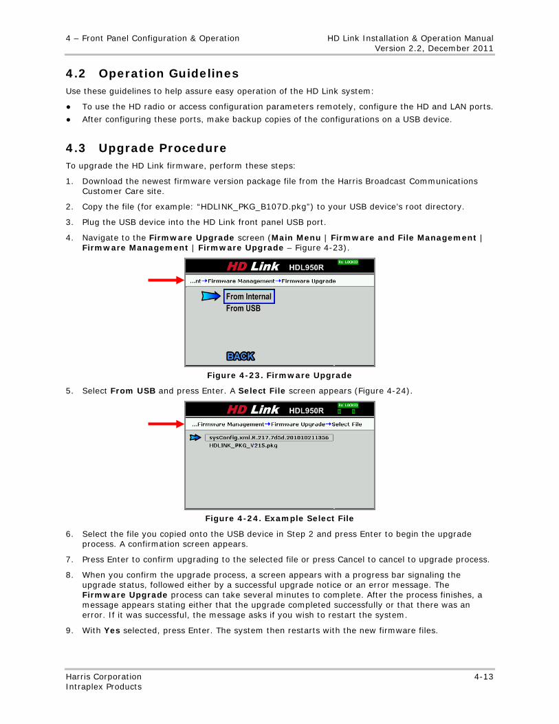
4 – Front Panel Configuration & Operation HD Link Installation & Operation Manual Version 2.2, December 2011
Harris Corporation 4-13 Intraplex Products
4.2 Operation Guidelines Use these guidelines to help assure easy operation of the HD Link system:
● To use the HD radio or access configuration parameters remotely, configure the HD and LAN ports.
● After configuring these ports, make backup copies of the configurations on a USB device.
4.3 Upgrade Procedure To upgrade the HD Link firmware, perform these steps:
1. Download the newest firmware version package file from the Harris Broadcast Communications Customer Care site.
2. Copy the file (for example: “HDLINK_PKG_B107D.pkg”) to your USB device’s root directory.
3. Plug the USB device into the HD Link front panel USB port.
4. Navigate to the Firmware Upgrade screen (Main Menu | Firmware and File Management | Firmware Management | Firmware Upgrade – Figure 4-23).
Figure 4-23. Firmware Upgrade
5. Select From USB and press Enter. A Select File screen appears (Figure 4-24).
Figure 4-24. Example Select File
6. Select the file you copied onto the USB device in Step 2 and press Enter to begin the upgrade process. A confirmation screen appears.
7. Press Enter to confirm upgrading to the selected file or press Cancel to cancel to upgrade process.
8. When you confirm the upgrade process, a screen appears with a progress bar signaling the upgrade status, followed either by a successful upgrade notice or an error message. The Firmware Upgrade process can take several minutes to complete. After the process finishes, a message appears stating either that the upgrade completed successfully or that there was an error. If it was successful, the message asks if you wish to restart the system.
9. With Yes selected, press Enter. The system then restarts with the new firmware files.
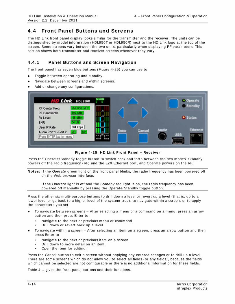
HD Link Installation & Operation Manual 4 – Front Panel Configuration & Operation Version 2.2, December 2011
4-14 Harris Corporation Intraplex Products
4.4 Front Panel Buttons and Screens The HD Link front panel display looks similar for the transmitter and the receiver. The units can be distinguished by model information (HDL950T or HDL950R) next to the HD Link logo at the top of the screen. Some screens vary between the two units, particularly when displaying RF parameters. This section shows both transmitter and receiver screens whenever they vary.
4.4.1 Panel Buttons and Screen Navigation
The front panel has seven blue buttons (Figure 4-25) you can use to
● Toggle between operating and standby.
● Navigate between screens and within screens.
● Add or change any configurations.
Figure 4-25. HD Link Front Panel – Receiver
Press the Operate/Standby toggle button to switch back and forth between the two modes. Standby powers off the radio frequency (RF) and the E2X Ethernet port, and Operate powers on the RF.
Notes: If the Operate green light on the front panel blinks, the radio frequency has been powered off on the Web browser interface. If the Operate light is off and the Standby red light is on, the radio frequency has been powered off manually by pressing the Operate/Standby toggle button.
Press the other six multi-purpose buttons to drill down a level or revert up a level (that is, go to a lower level or go back to a higher level of the system tree), to navigate within a screen, or to apply the parameters you set.
● To navigate between screens – After selecting a menu or a command on a menu, press an arrow button and then press Enter to
• Navigate to the next or previous menu or command. • Drill down or revert back up a level.
● To navigate within a screen – After selecting an item on a screen, press an arrow button and then press Enter to
• Navigate to the next or previous item on a screen. • Drill down to more detail on an item. • Open the item for editing.
Press the Cancel button to exit a screen without applying any entered changes or to drill up a level. There are some screens which do not allow you to select all fields (or any fields), because the fields which cannot be selected are not configurable or there is no additional information for these fields.
Table 4-1 gives the front panel buttons and their functions.
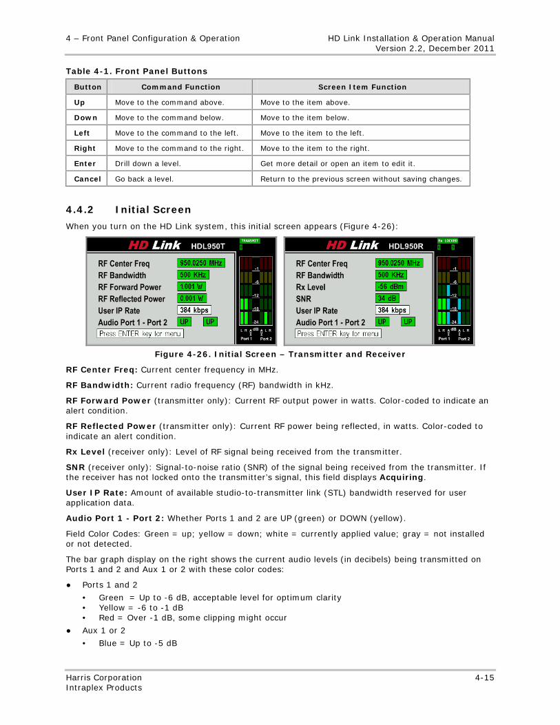
4 – Front Panel Configuration & Operation HD Link Installation & Operation Manual Version 2.2, December 2011
Harris Corporation 4-15 Intraplex Products
Table 4-1. Front Panel Buttons
Button Command Function Screen Item Function
Up Move to the command above. Move to the item above.
Down Move to the command below. Move to the item below.
Left Move to the command to the left. Move to the item to the left.
Right Move to the command to the right. Move to the item to the right.
Enter Drill down a level. Get more detail or open an item to edit it.
Cancel Go back a level. Return to the previous screen without saving changes.
4.4.2 Initial Screen
When you turn on the HD Link system, this initial screen appears (Figure 4-26):
Figure 4-26. Initial Screen – Transmitter and Receiver
RF Center Freq: Current center frequency in MHz.
RF Bandwidth: Current radio frequency (RF) bandwidth in kHz.
RF Forward Power (transmitter only): Current RF output power in watts. Color-coded to indicate an alert condition.
RF Reflected Power (transmitter only): Current RF power being reflected, in watts. Color-coded to indicate an alert condition.
Rx Level (receiver only): Level of RF signal being received from the transmitter.
SNR (receiver only): Signal-to-noise ratio (SNR) of the signal being received from the transmitter. If the receiver has not locked onto the transmitter’s signal, this field displays Acquiring.
User IP Rate: Amount of available studio-to-transmitter link (STL) bandwidth reserved for user application data.
Audio Port 1 - Port 2: Whether Ports 1 and 2 are UP (green) or DOWN (yellow).
Field Color Codes: Green = up; yellow = down; white = currently applied value; gray = not installed or not detected.
The bar graph display on the right shows the current audio levels (in decibels) being transmitted on Ports 1 and 2 and Aux 1 or 2 with these color codes:
● Ports 1 and 2
• Green = Up to -6 dB, acceptable level for optimum clarity • Yellow = -6 to -1 dB • Red = Over -1 dB, some clipping might occur
● Aux 1 or 2
• Blue = Up to -5 dB
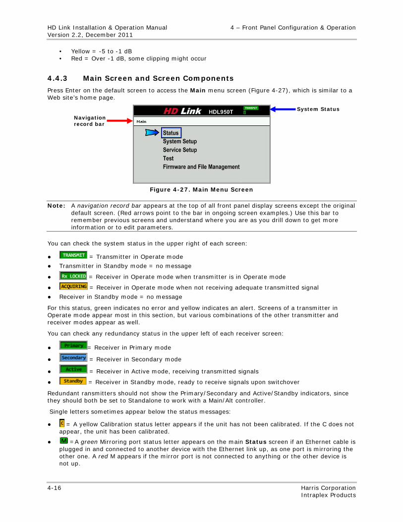
HD Link Installation & Operation Manual 4 – Front Panel Configuration & Operation Version 2.2, December 2011
4-16 Harris Corporation Intraplex Products
• Yellow = -5 to -1 dB • Red = Over -1 dB, some clipping might occur
4.4.3 Main Screen and Screen Components
Press Enter on the default screen to access the Main menu screen (Figure 4-27), which is similar to a Web site’s home page.
Figure 4-27. Main Menu Screen
Note: A navigation record bar appears at the top of all front panel display screens except the original default screen. (Red arrows point to the bar in ongoing screen examples.) Use this bar to remember previous screens and understand where you are as you drill down to get more information or to edit parameters.
You can check the system status in the upper right of each screen:
● = Transmitter in Operate mode
● Transmitter in Standby mode = no message
● = Receiver in Operate mode when transmitter is in Operate mode
● = Receiver in Operate mode when not receiving adequate transmitted signal
● Receiver in Standby mode = no message
For this status, green indicates no error and yellow indicates an alert. Screens of a transmitter in Operate mode appear most in this section, but various combinations of the other transmitter and receiver modes appear as well.
You can check any redundancy status in the upper left of each receiver screen:
● = Receiver in Primary mode
● = Receiver in Secondary mode
● = Receiver in Active mode, receiving transmitted signals
● = Receiver in Standby mode, ready to receive signals upon switchover
Redundant ransmitters should not show the Primary/Secondary and Active/Standby indicators, since they should both be set to Standalone to work with a Main/Alt controller.
Single letters sometimes appear below the status messages:
● = A yellow Calibration status letter appears if the unit has not been calibrated. If the C does not appear, the unit has been calibrated.
● =A green Mirroring port status letter appears on the main Status screen if an Ethernet cable is plugged in and connected to another device with the Ethernet link up, as one port is mirroring the other one. A red M appears if the mirror port is not connected to anything or the other device is not up.
Navigation record bar
System Status
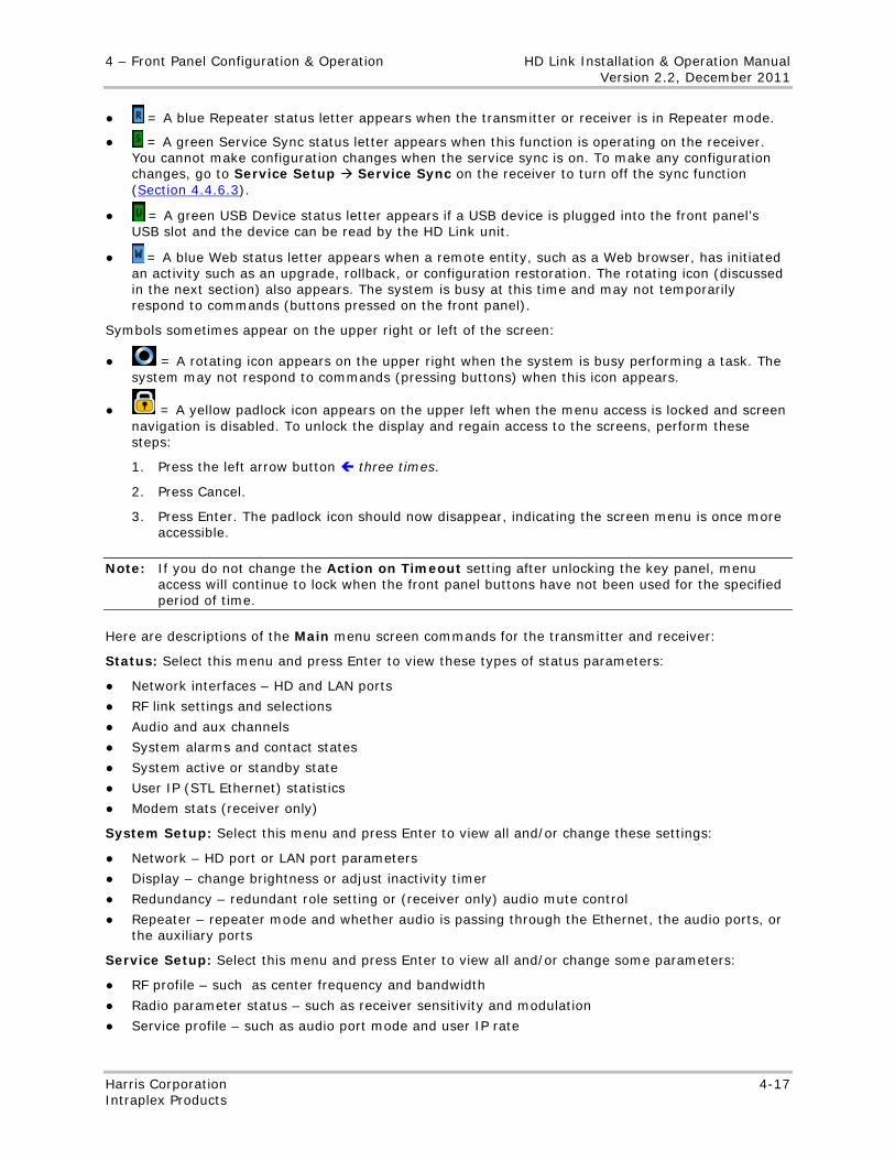
4 – Front Panel Configuration & Operation HD Link Installation & Operation Manual Version 2.2, December 2011
Harris Corporation 4-17 Intraplex Products
● = A blue Repeater status letter appears when the transmitter or receiver is in Repeater mode.
● = A green Service Sync status letter appears when this function is operating on the receiver. You cannot make configuration changes when the service sync is on. To make any configuration changes, go to Service Setup Service Sync on the receiver to turn off the sync function (Section 4.4.6.3).
● = A green USB Device status letter appears if a USB device is plugged into the front panel’s USB slot and the device can be read by the HD Link unit.
● = A blue Web status letter appears when a remote entity, such as a Web browser, has initiated an activity such as an upgrade, rollback, or configuration restoration. The rotating icon (discussed in the next section) also appears. The system is busy at this time and may not temporarily respond to commands (buttons pressed on the front panel).
Symbols sometimes appear on the upper right or left of the screen:
● = A rotating icon appears on the upper right when the system is busy performing a task. The system may not respond to commands (pressing buttons) when this icon appears.
● = A yellow padlock icon appears on the upper left when the menu access is locked and screen navigation is disabled. To unlock the display and regain access to the screens, perform these steps:
1. Press the left arrow button three times.
2. Press Cancel.
3. Press Enter. The padlock icon should now disappear, indicating the screen menu is once more accessible.
Note: If you do not change the Action on Timeout setting after unlocking the key panel, menu access will continue to lock when the front panel buttons have not been used for the specified period of time.
Here are descriptions of the Main menu screen commands for the transmitter and receiver:
Status: Select this menu and press Enter to view these types of status parameters:
● Network interfaces – HD and LAN ports
● RF link settings and selections
● Audio and aux channels
● System alarms and contact states
● System active or standby state
● User IP (STL Ethernet) statistics
● Modem stats (receiver only)
System Setup: Select this menu and press Enter to view all and/or change these settings:
● Network – HD port or LAN port parameters
● Display – change brightness or adjust inactivity timer
● Redundancy – redundant role setting or (receiver only) audio mute control
● Repeater – repeater mode and whether audio is passing through the Ethernet, the audio ports, or the auxiliary ports
Service Setup: Select this menu and press Enter to view all and/or change some parameters:
● RF profile – such as center frequency and bandwidth
● Radio parameter status – such as receiver sensitivity and modulation
● Service profile – such as audio port mode and user IP rate
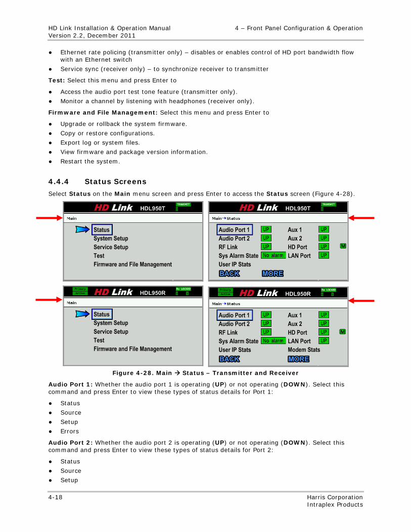
HD Link Installation & Operation Manual 4 – Front Panel Configuration & Operation Version 2.2, December 2011
4-18 Harris Corporation Intraplex Products
● Ethernet rate policing (transmitter only) – disables or enables control of HD port bandwidth flow with an Ethernet switch
● Service sync (receiver only) – to synchronize receiver to transmitter
Test: Select this menu and press Enter to
● Access the audio port test tone feature (transmitter only).
● Monitor a channel by listening with headphones (receiver only).
Firmware and File Management: Select this menu and press Enter to
● Upgrade or rollback the system firmware.
● Copy or restore configurations.
● Export log or system files.
● View firmware and package version information.
● Restart the system.
4.4.4 Status Screens
Select Status on the Main menu screen and press Enter to access the Status screen (Figure 4-28).
Figure 4-28. Main Status – Transmitter and Receiver
Audio Port 1: Whether the audio port 1 is operating (UP) or not operating (DOWN). Select this command and press Enter to view these types of status details for Port 1:
● Status
● Source
● Setup
● Errors
Audio Port 2: Whether the audio port 2 is operating (UP) or not operating (DOWN). Select this command and press Enter to view these types of status details for Port 2:
● Status
● Source
● Setup
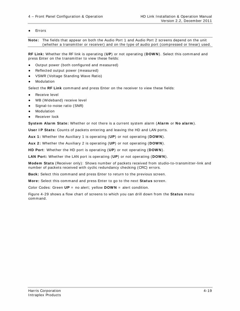
4 – Front Panel Configuration & Operation HD Link Installation & Operation Manual Version 2.2, December 2011
Harris Corporation 4-19 Intraplex Products
● Errors
Note: The fields that appear on both the Audio Port 1 and Audio Port 2 screens depend on the unit (whether a transmitter or receiver) and on the type of audio port (compressed or linear) used.
RF Link: Whether the RF link is operating (UP) or not operating (DOWN). Select this command and press Enter on the transmitter to view these fields:
● Output power (both configured and measured)
● Reflected output power (measured)
● VSWR (Voltage Standing Wave Ratio)
● Modulation
Select the RF Link command and press Enter on the receiver to view these fields:
● Receive level
● WB (Wideband) receive level
● Signal-to-noise ratio (SNR)
● Modulation
● Receiver lock
System Alarm State: Whether or not there is a current system alarm (Alarm or No alarm).
User IP Stats: Counts of packets entering and leaving the HD and LAN ports.
Aux 1: Whether the Auxiliary 1 is operating (UP) or not operating (DOWN).
Aux 2: Whether the Auxiliary 2 is operating (UP) or not operating (DOWN).
HD Port: Whether the HD port is operating (UP) or not operating (DOWN).
LAN Port: Whether the LAN port is operating (UP) or not operating (DOWN).
Modem Stats (Receiver only): Shows number of packets received from studio-to-transmitter-link and number of packets received with cyclic redundancy checking (CRC) errors.
Back: Select this command and press Enter to return to the previous screen.
More: Select this command and press Enter to go to the next Status screen.
Color Codes: Green UP = no alert; yellow DOWN = alert condition.
Figure 4-29 shows a flow chart of screens to which you can drill down from the Status menu command.
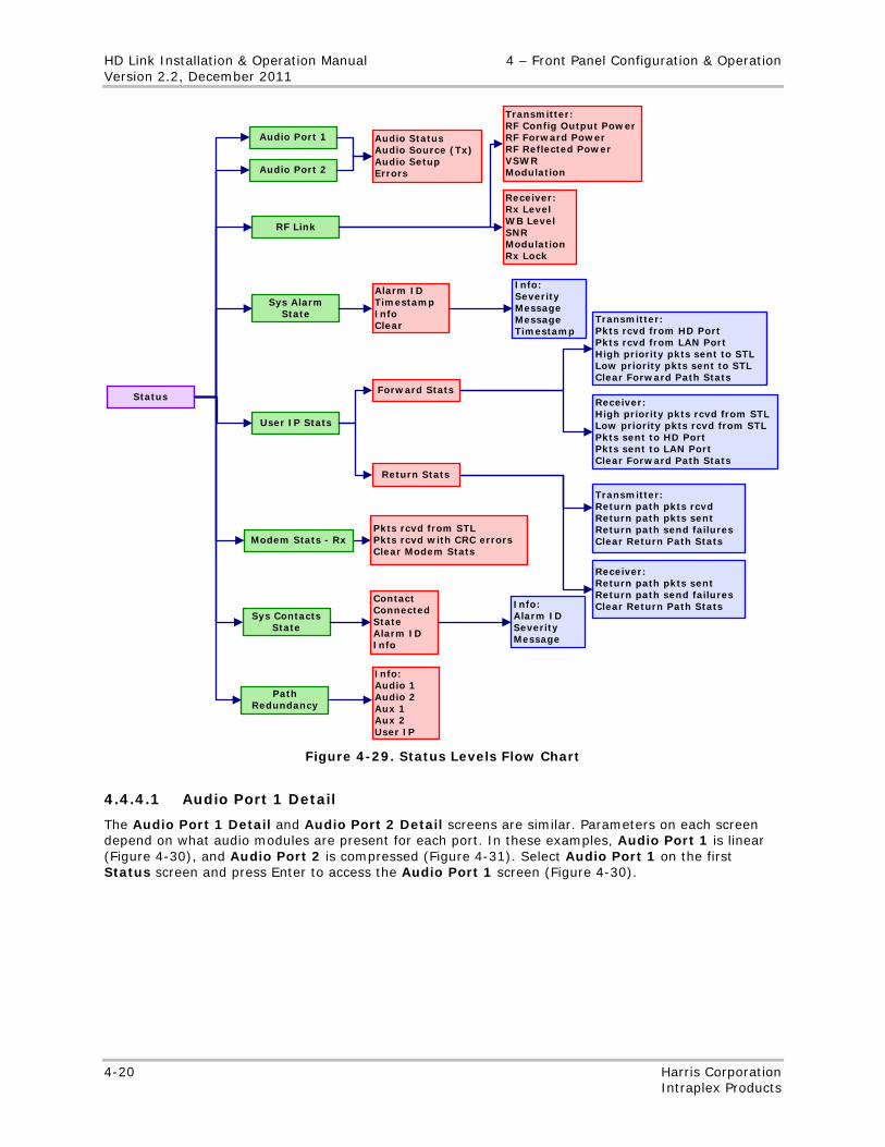
HD Link Installation & Operation Manual 4 – Front Panel Configuration & Operation Version 2.2, December 2011
4-20 Harris Corporation Intraplex Products
Audio Port 1
Audio Port 2
RF Link
Sys Alarm State
Sys Contacts State
User IP Stats
StatusForward Stats
Return Stats
Audio StatusAudio Source (Tx)Audio SetupErrors
Alarm IDTimestampInfoClear
ContactConnectedStateAlarm IDInfo
Transmitter:Return path pkts rcvdReturn path pkts sentReturn path send failuresClear Return Path Stats
Transmitter:Pkts rcvd from HD PortPkts rcvd from LAN PortHigh priority pkts sent to STLLow priority pkts sent to STLClear Forward Path Stats
Receiver:High priority pkts rcvd from STLLow priority pkts rcvd from STLPkts sent to HD PortPkts sent to LAN PortClear Forward Path Stats
Receiver:Return path pkts sentReturn path send failuresClear Return Path Stats
Receiver:Rx LevelWB LevelSNRModulationRx Lock
Transmitter:RF Config Output PowerRF Forward PowerRF Reflected PowerVSWRModulation
Info:Alarm IDSeverityMessage
Info:SeverityMessageMessageTimestamp
Modem Stats - RxPkts rcvd from STLPkts rcvd with CRC errorsClear Modem Stats
Path Redundancy
Info:Audio 1Audio 2Aux 1Aux 2User IP
Figure 4-29. Status Levels Flow Chart
4.4.4.1 Audio Port 1 Detail
The Audio Port 1 Detail and Audio Port 2 Detail screens are similar. Parameters on each screen depend on what audio modules are present for each port. In these examples, Audio Port 1 is linear (Figure 4-30), and Audio Port 2 is compressed (Figure 4-31). Select Audio Port 1 on the first Status screen and press Enter to access the Audio Port 1 screen (Figure 4-30).
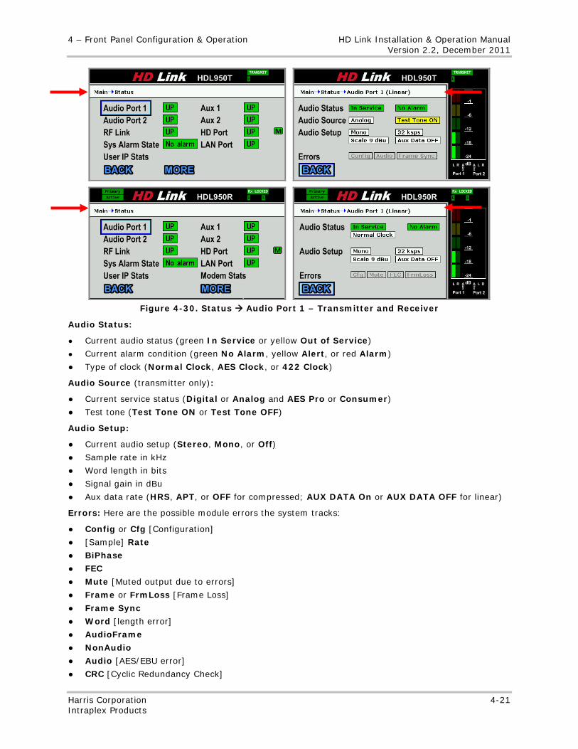
4 – Front Panel Configuration & Operation HD Link Installation & Operation Manual Version 2.2, December 2011
Harris Corporation 4-21 Intraplex Products
Figure 4-30. Status Audio Port 1 – Transmitter and Receiver
Audio Status:
● Current audio status (green In Service or yellow Out of Service)
● Current alarm condition (green No Alarm, yellow Alert, or red Alarm)
● Type of clock (Normal Clock, AES Clock, or 422 Clock)
Audio Source (transmitter only):
● Current service status (Digital or Analog and AES Pro or Consumer)
● Test tone (Test Tone ON or Test Tone OFF)
Audio Setup:
● Current audio setup (Stereo, Mono, or Off)
● Sample rate in kHz
● Word length in bits
● Signal gain in dBu
● Aux data rate (HRS, APT, or OFF for compressed; AUX DATA On or AUX DATA OFF for linear)
Errors: Here are the possible module errors the system tracks:
● Config or Cfg [Configuration]
● [Sample] Rate
● BiPhase
● FEC
● Mute [Muted output due to errors]
● Frame or FrmLoss [Frame Loss]
● Frame Sync
● Word [length error]
● AudioFrame
● NonAudio
● Audio [AES/EBU error]
● CRC [Cyclic Redundancy Check]
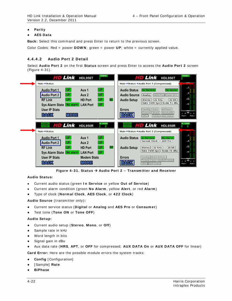
HD Link Installation & Operation Manual 4 – Front Panel Configuration & Operation Version 2.2, December 2011
4-22 Harris Corporation Intraplex Products
● Parity
● AES Data
Back: Select this command and press Enter to return to the previous screen.
Color Codes: Red = power DOWN; green = power UP; white = currently applied value.
4.4.4.2 Audio Port 2 Detail
Select Audio Port 2 on the first Status screen and press Enter to access the Audio Port 2 screen (Figure 4-31).
Figure 4-31. Status Audio Port 2 – Transmitter and Receiver
Audio Status:
● Current audio status (green In Service or yellow Out of Service)
● Current alarm condition (green No Alarm, yellow Alert, or red Alarm)
● Type of clock (Normal Clock, AES Clock, or 422 Clock)
Audio Source (transmitter only):
● Current service status (Digital or Analog and AES Pro or Consumer)
● Test tone (Tone ON or Tone OFF)
Audio Setup:
● Current audio setup (Stereo, Mono, or Off)
● Sample rate in kHz
● Word length in bits
● Signal gain in dBu
● Aux data rate (HRS, APT, or OFF for compressed; AUX DATA On or AUX DATA OFF for linear)
Card Error: Here are the possible module errors the system tracks:
● Config [Configuration]
● [Sample] Rate
● BiPhase
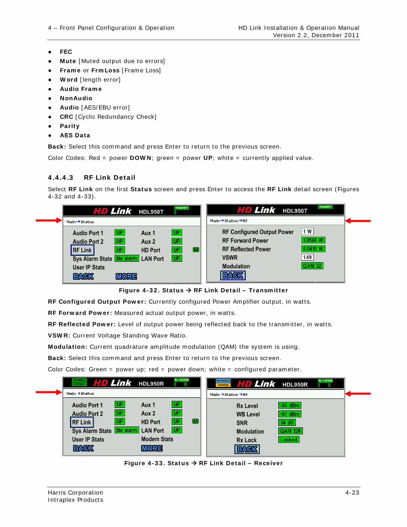
4 – Front Panel Configuration & Operation HD Link Installation & Operation Manual Version 2.2, December 2011
Harris Corporation 4-23 Intraplex Products
● FEC
● Mute [Muted output due to errors]
● Frame or FrmLoss [Frame Loss]
● Word [length error]
● Audio Frame
● NonAudio
● Audio [AES/EBU error]
● CRC [Cyclic Redundancy Check]
● Parity
● AES Data
Back: Select this command and press Enter to return to the previous screen.
Color Codes: Red = power DOWN; green = power UP; white = currently applied value.
4.4.4.3 RF Link Detail
Select RF Link on the first Status screen and press Enter to access the RF Link detail screen (Figures 4-32 and 4-33).
Figure 4-32. Status RF Link Detail – Transmitter
RF Configured Output Power: Currently configured Power Amplifier output, in watts.
RF Forward Power: Measured actual output power, in watts.
RF Reflected Power: Level of output power being reflected back to the transmitter, in watts.
VSWR: Current Voltage Standing Wave Ratio.
Modulation: Current quadrature amplitude modulation (QAM) the system is using.
Back: Select this command and press Enter to return to the previous screen.
Color Codes: Green = power up; red = power down; white = configured parameter.
Figure 4-33. Status RF Link Detail – Receiver
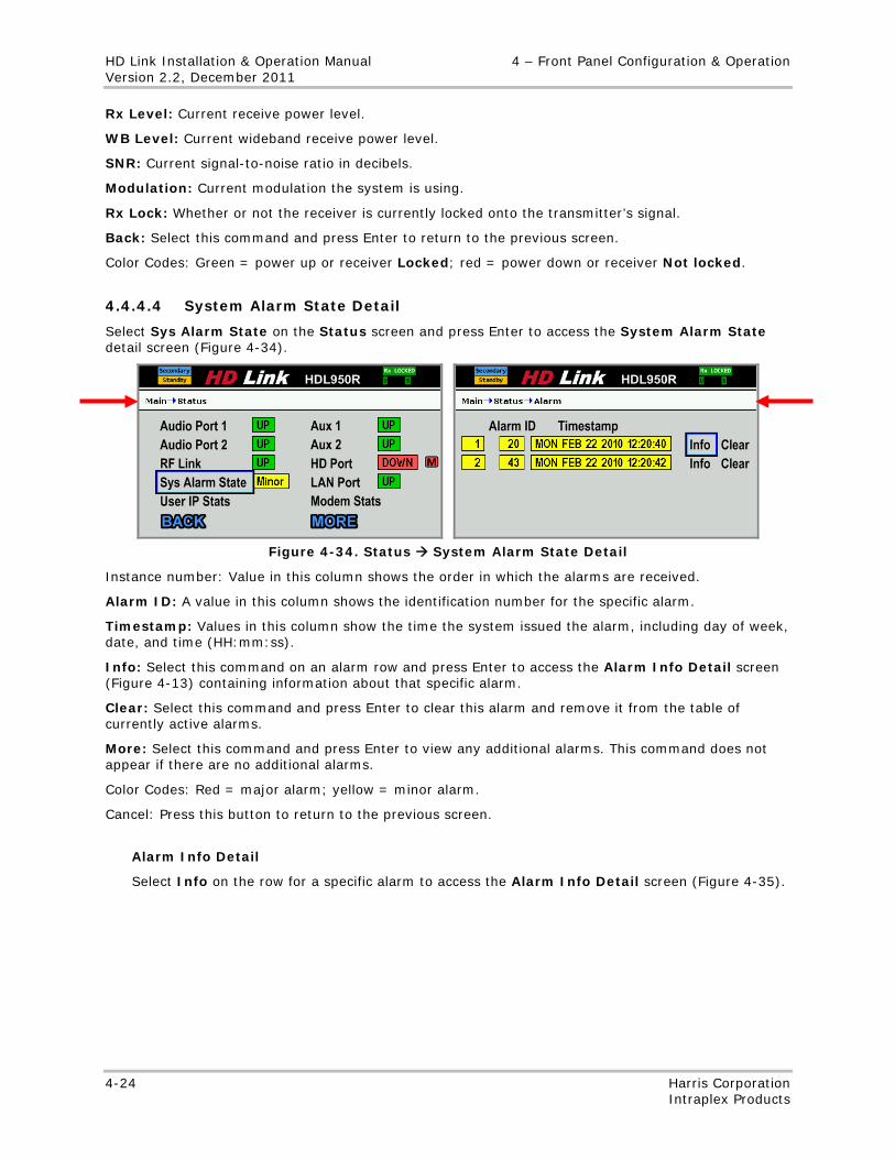
HD Link Installation & Operation Manual 4 – Front Panel Configuration & Operation Version 2.2, December 2011
4-24 Harris Corporation Intraplex Products
Rx Level: Current receive power level.
WB Level: Current wideband receive power level.
SNR: Current signal-to-noise ratio in decibels.
Modulation: Current modulation the system is using.
Rx Lock: Whether or not the receiver is currently locked onto the transmitter’s signal.
Back: Select this command and press Enter to return to the previous screen.
Color Codes: Green = power up or receiver Locked; red = power down or receiver Not locked.
4.4.4.4 System Alarm State Detail
Select Sys Alarm State on the Status screen and press Enter to access the System Alarm State detail screen (Figure 4-34).
Figure 4-34. Status System Alarm State Detail
Instance number: Value in this column shows the order in which the alarms are received.
Alarm ID: A value in this column shows the identification number for the specific alarm.
Timestamp: Values in this column show the time the system issued the alarm, including day of week, date, and time (HH:mm:ss).
Info: Select this command on an alarm row and press Enter to access the Alarm Info Detail screen (Figure 4-13) containing information about that specific alarm.
Clear: Select this command and press Enter to clear this alarm and remove it from the table of currently active alarms.
More: Select this command and press Enter to view any additional alarms. This command does not appear if there are no additional alarms.
Color Codes: Red = major alarm; yellow = minor alarm.
Cancel: Press this button to return to the previous screen.
Alarm Info Detail
Select Info on the row for a specific alarm to access the Alarm Info Detail screen (Figure 4-35).
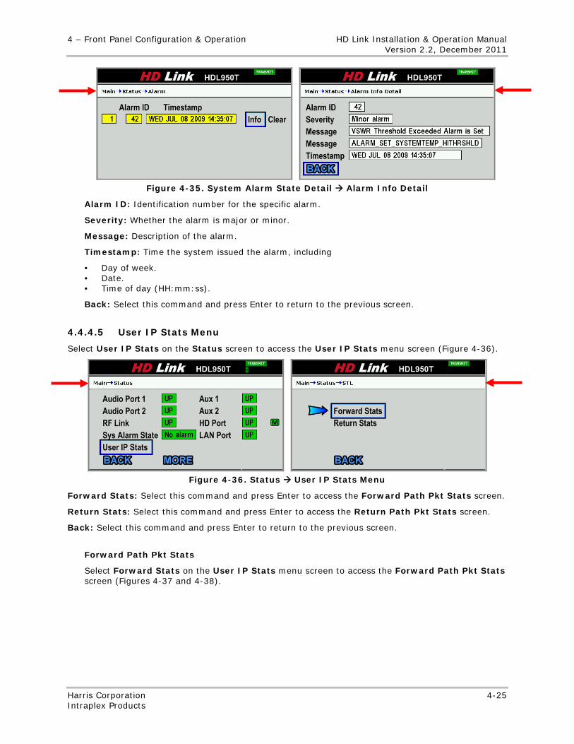
4 – Front Panel Configuration & Operation HD Link Installation & Operation Manual Version 2.2, December 2011
Harris Corporation 4-25 Intraplex Products
Figure 4-35. System Alarm State Detail Alarm Info Detail
Alarm ID: Identification number for the specific alarm.
Severity: Whether the alarm is major or minor.
Message: Description of the alarm.
Timestamp: Time the system issued the alarm, including
• Day of week. • Date. • Time of day (HH:mm:ss).
Back: Select this command and press Enter to return to the previous screen.
4.4.4.5 User IP Stats Menu
Select User IP Stats on the Status screen to access the User IP Stats menu screen (Figure 4-36).
Figure 4-36. Status User IP Stats Menu
Forward Stats: Select this command and press Enter to access the Forward Path Pkt Stats screen.
Return Stats: Select this command and press Enter to access the Return Path Pkt Stats screen.
Back: Select this command and press Enter to return to the previous screen.
Forward Path Pkt Stats
Select Forward Stats on the User IP Stats menu screen to access the Forward Path Pkt Stats screen (Figures 4-37 and 4-38).
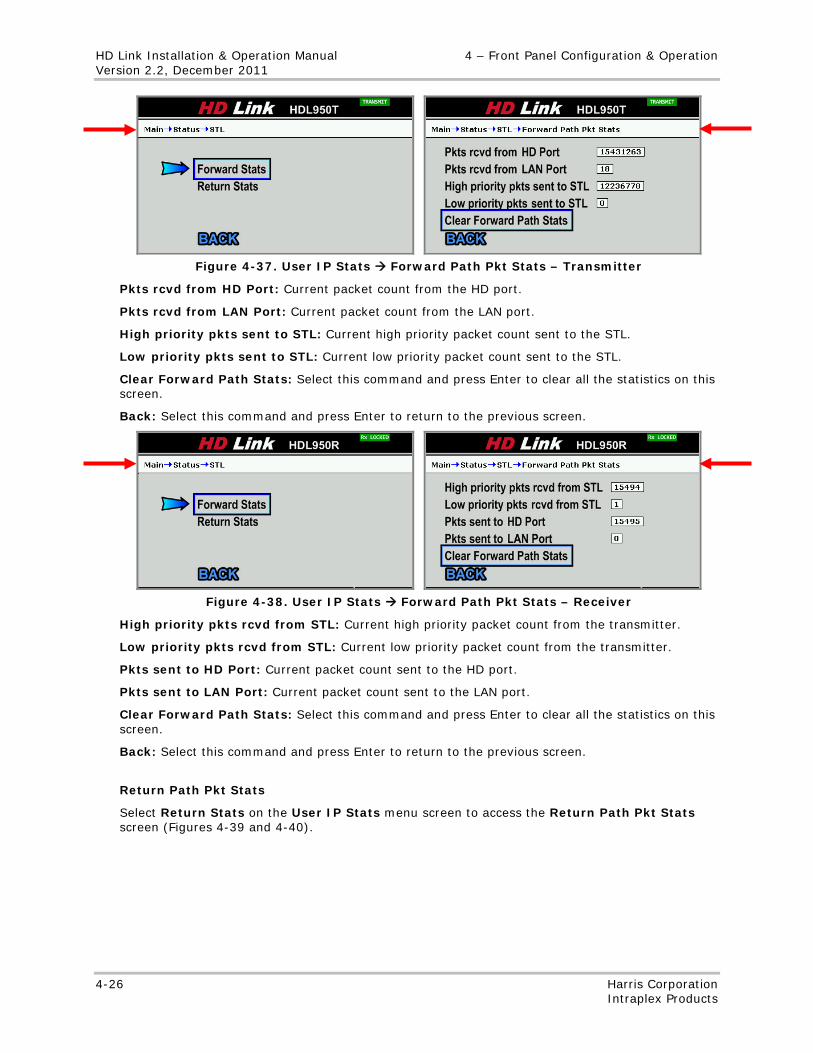
HD Link Installation & Operation Manual 4 – Front Panel Configuration & Operation Version 2.2, December 2011
4-26 Harris Corporation Intraplex Products
Figure 4-37. User IP Stats Forward Path Pkt Stats – Transmitter
Pkts rcvd from HD Port: Current packet count from the HD port.
Pkts rcvd from LAN Port: Current packet count from the LAN port.
High priority pkts sent to STL: Current high priority packet count sent to the STL.
Low priority pkts sent to STL: Current low priority packet count sent to the STL.
Clear Forward Path Stats: Select this command and press Enter to clear all the statistics on this screen.
Back: Select this command and press Enter to return to the previous screen.
Figure 4-38. User IP Stats Forward Path Pkt Stats – Receiver
High priority pkts rcvd from STL: Current high priority packet count from the transmitter.
Low priority pkts rcvd from STL: Current low priority packet count from the transmitter.
Pkts sent to HD Port: Current packet count sent to the HD port.
Pkts sent to LAN Port: Current packet count sent to the LAN port.
Clear Forward Path Stats: Select this command and press Enter to clear all the statistics on this screen.
Back: Select this command and press Enter to return to the previous screen.
Return Path Pkt Stats
Select Return Stats on the User IP Stats menu screen to access the Return Path Pkt Stats screen (Figures 4-39 and 4-40).
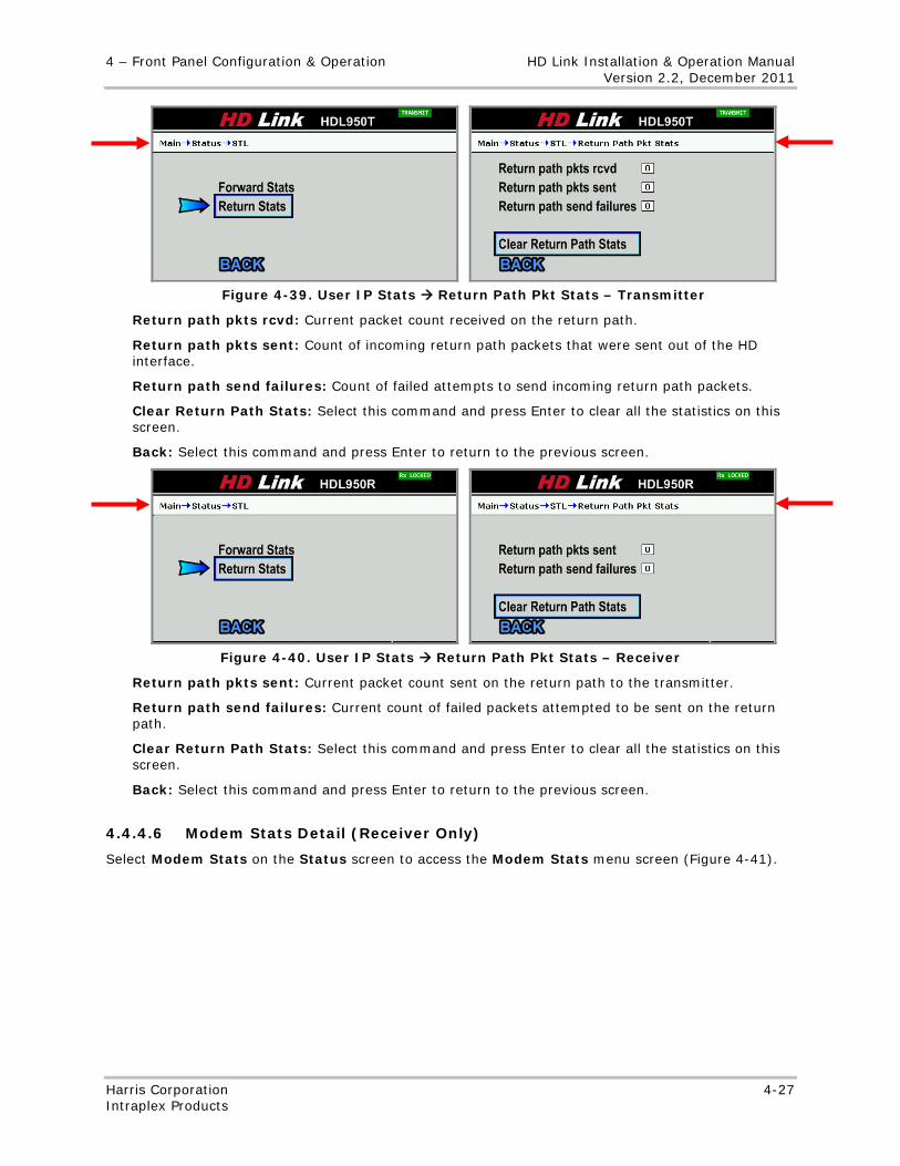
4 – Front Panel Configuration & Operation HD Link Installation & Operation Manual Version 2.2, December 2011
Harris Corporation 4-27 Intraplex Products
Figure 4-39. User IP Stats Return Path Pkt Stats – Transmitter
Return path pkts rcvd: Current packet count received on the return path.
Return path pkts sent: Count of incoming return path packets that were sent out of the HD interface.
Return path send failures: Count of failed attempts to send incoming return path packets.
Clear Return Path Stats: Select this command and press Enter to clear all the statistics on this screen.
Back: Select this command and press Enter to return to the previous screen.
Figure 4-40. User IP Stats Return Path Pkt Stats – Receiver
Return path pkts sent: Current packet count sent on the return path to the transmitter.
Return path send failures: Current count of failed packets attempted to be sent on the return path.
Clear Return Path Stats: Select this command and press Enter to clear all the statistics on this screen.
Back: Select this command and press Enter to return to the previous screen.
4.4.4.6 Modem Stats Detail (Receiver Only)
Select Modem Stats on the Status screen to access the Modem Stats menu screen (Figure 4-41).
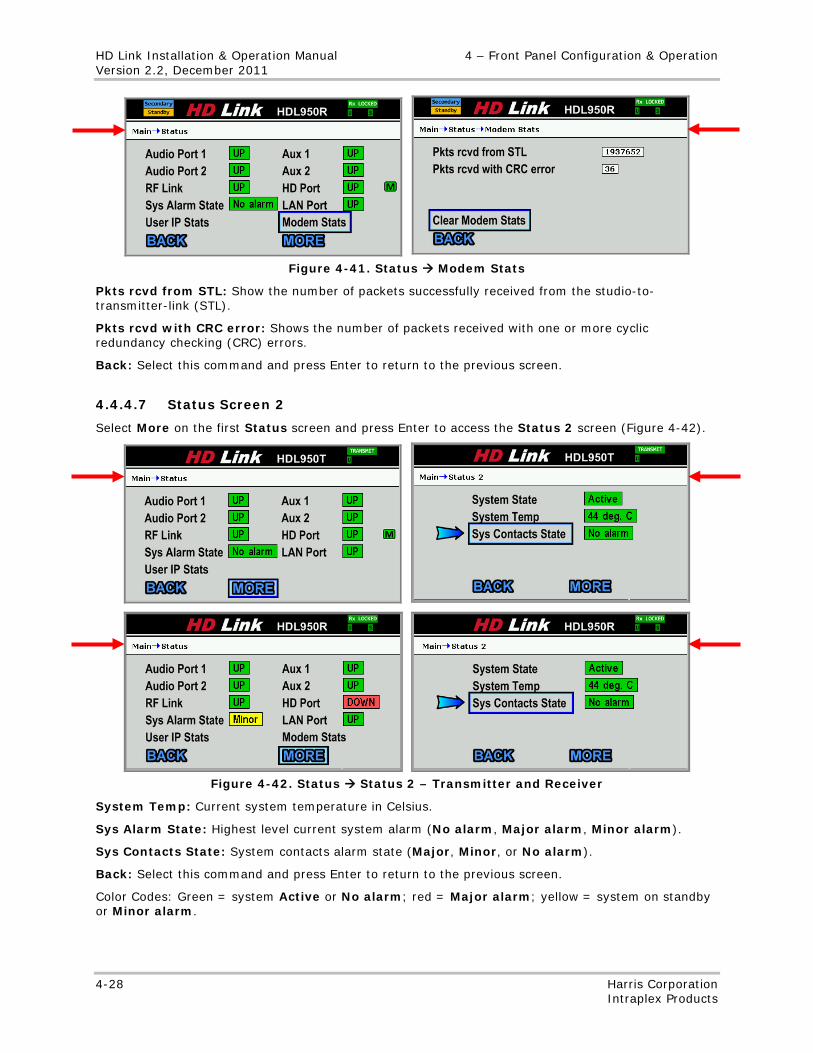
HD Link Installation & Operation Manual 4 – Front Panel Configuration & Operation Version 2.2, December 2011
4-28 Harris Corporation Intraplex Products
Figure 4-41. Status Modem Stats
Pkts rcvd from STL: Show the number of packets successfully received from the studio-to-transmitter-link (STL).
Pkts rcvd with CRC error: Shows the number of packets received with one or more cyclic redundancy checking (CRC) errors.
Back: Select this command and press Enter to return to the previous screen.
4.4.4.7 Status Screen 2
Select More on the first Status screen and press Enter to access the Status 2 screen (Figure 4-42).
Figure 4-42. Status Status 2 – Transmitter and Receiver
System Temp: Current system temperature in Celsius.
Sys Alarm State: Highest level current system alarm (No alarm, Major alarm, Minor alarm).
Sys Contacts State: System contacts alarm state (Major, Minor, or No alarm).
Back: Select this command and press Enter to return to the previous screen.
Color Codes: Green = system Active or No alarm; red = Major alarm; yellow = system on standby or Minor alarm.
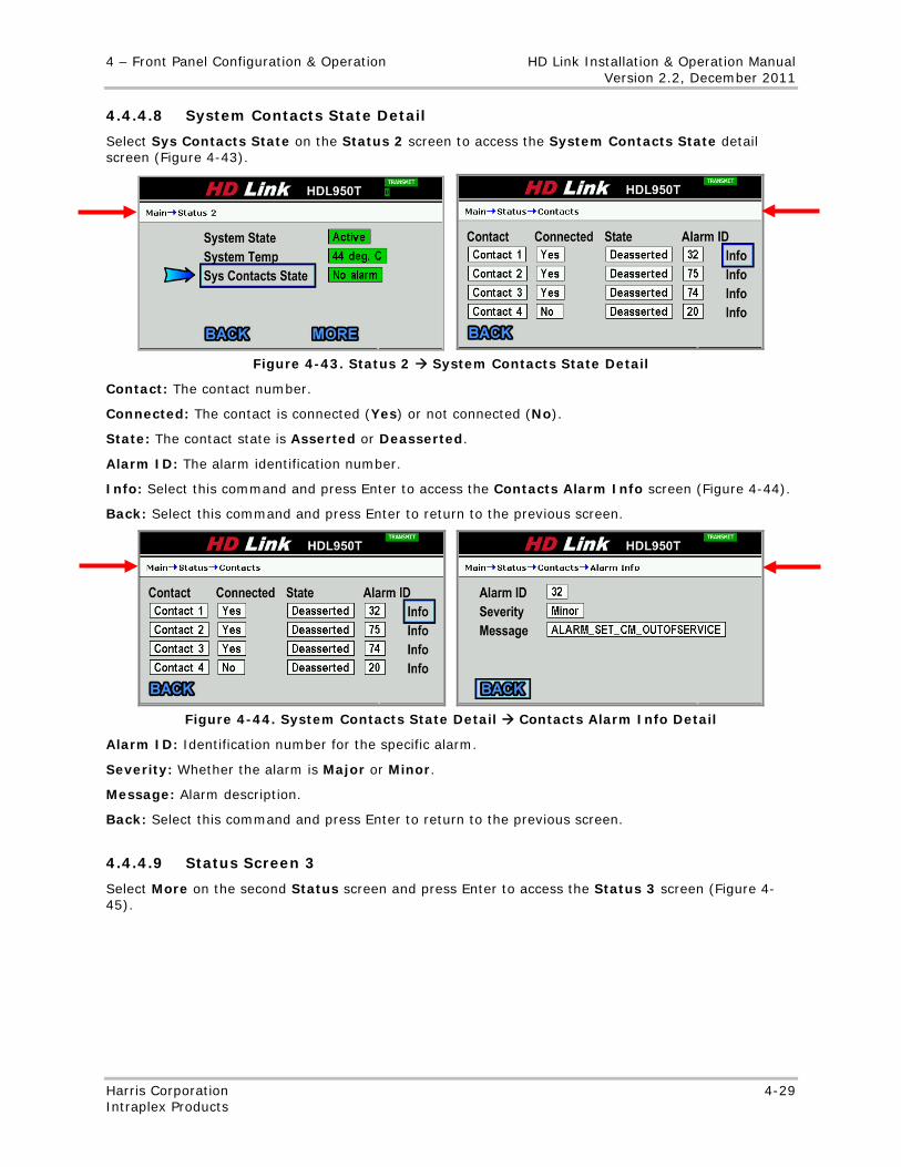
4 – Front Panel Configuration & Operation HD Link Installation & Operation Manual Version 2.2, December 2011
Harris Corporation 4-29 Intraplex Products
4.4.4.8 System Contacts State Detail
Select Sys Contacts State on the Status 2 screen to access the System Contacts State detail screen (Figure 4-43).
Figure 4-43. Status 2 System Contacts State Detail
Contact: The contact number.
Connected: The contact is connected (Yes) or not connected (No).
State: The contact state is Asserted or Deasserted.
Alarm ID: The alarm identification number.
Info: Select this command and press Enter to access the Contacts Alarm Info screen (Figure 4-44).
Back: Select this command and press Enter to return to the previous screen.
Figure 4-44. System Contacts State Detail Contacts Alarm Info Detail
Alarm ID: Identification number for the specific alarm.
Severity: Whether the alarm is Major or Minor.
Message: Alarm description.
Back: Select this command and press Enter to return to the previous screen.
4.4.4.9 Status Screen 3
Select More on the second Status screen and press Enter to access the Status 3 screen (Figure 4-45).
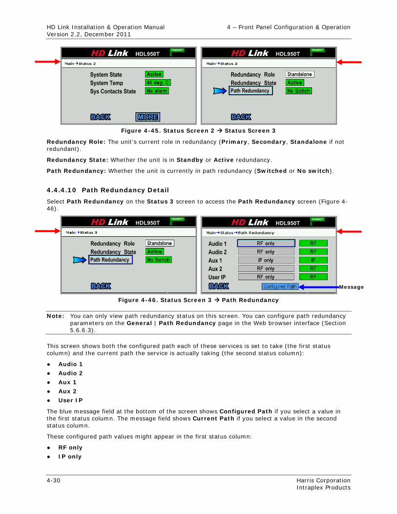
HD Link Installation & Operation Manual 4 – Front Panel Configuration & Operation Version 2.2, December 2011
4-30 Harris Corporation Intraplex Products
Figure 4-45. Status Screen 2 Status Screen 3
Redundancy Role: The unit’s current role in redundancy (Primary, Secondary, Standalone if not redundant).
Redundancy State: Whether the unit is in Standby or Active redundancy.
Path Redundancy: Whether the unit is currently in path redundancy (Switched or No switch).
4.4.4.10 Path Redundancy Detail
Select Path Redundancy on the Status 3 screen to access the Path Redundancy screen (Figure 4-46).
Figure 4-46. Status Screen 3 Path Redundancy
Note: You can only view path redundancy status on this screen. You can configure path redundancy parameters on the General | Path Redundancy page in the Web browser interface (Section 5.6.6.3).
This screen shows both the configured path each of these services is set to take (the first status column) and the current path the service is actually taking (the second status column):
● Audio 1
● Audio 2
● Aux 1
● Aux 2
● User IP
The blue message field at the bottom of the screen shows Configured Path if you select a value in the first status column. The message field shows Current Path if you select a value in the second status column.
These configured path values might appear in the first status column:
● RF only
● IP only
Message
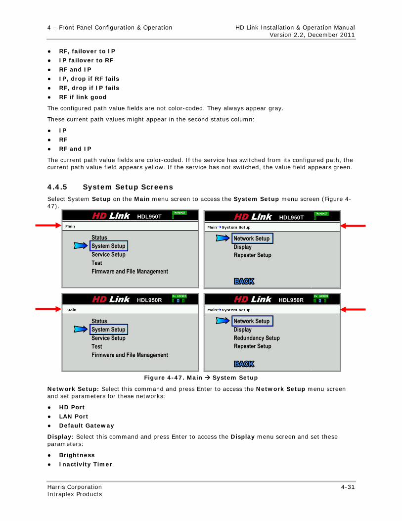
4 – Front Panel Configuration & Operation HD Link Installation & Operation Manual Version 2.2, December 2011
Harris Corporation 4-31 Intraplex Products
● RF, failover to IP
● IP failover to RF
● RF and IP
● IP, drop if RF fails
● RF, drop if IP fails
● RF if link good
The configured path value fields are not color-coded. They always appear gray.
These current path values might appear in the second status column:
● IP
● RF
● RF and IP
The current path value fields are color-coded. If the service has switched from its configured path, the current path value field appears yellow. If the service has not switched, the value field appears green.
4.4.5 System Setup Screens
Select System Setup on the Main menu screen to access the System Setup menu screen (Figure 4-47).
Figure 4-47. Main System Setup
Network Setup: Select this command and press Enter to access the Network Setup menu screen and set parameters for these networks:
● HD Port
● LAN Port
● Default Gateway
Display: Select this command and press Enter to access the Display menu screen and set these parameters:
● Brightness
● Inactivity Timer
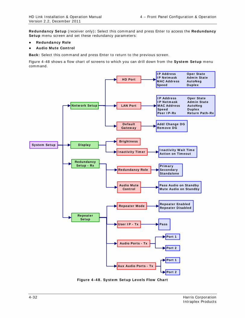
HD Link Installation & Operation Manual 4 – Front Panel Configuration & Operation Version 2.2, December 2011
4-32 Harris Corporation Intraplex Products
Redundancy Setup (receiver only): Select this command and press Enter to access the Redundancy Setup menu screen and set these redundancy parameters:
● Redundancy Role
● Audio Mute Control
Back: Select this command and press Enter to return to the previous screen.
Figure 4-48 shows a flow chart of screens to which you can drill down from the System Setup menu command.
System Setup
Network Setup
Display
Redundancy Setup - Rx
Inactivity Timer
Brightness
Inactivity Wait TimeAction on Timeout
HD Port
LAN Port
Default Gateway
Add/Change DGRemove DG
IP Address Oper StateIP Netmask Admin StateMAC Address AutoNegSpeed DuplexPeer IP-Rx Return Path-Rx
IP Address Oper StateIP Netmask Admin StateMAC Address AutoNegSpeed Duplex
Redundancy Role
Audio Mute Control
PrimarySecondaryStandalone
Pass Audio on StandbyMute Audio on Standby
Repeater Setup
User IP - Tx
Repeater Mode
Aux Audio Ports - Tx
Audio Ports - Tx
Repeater EnabledRepeater Disabled
Pass
Port 1
Port 2
Port 1
Port 2
Figure 4-48. System Setup Levels Flow Chart
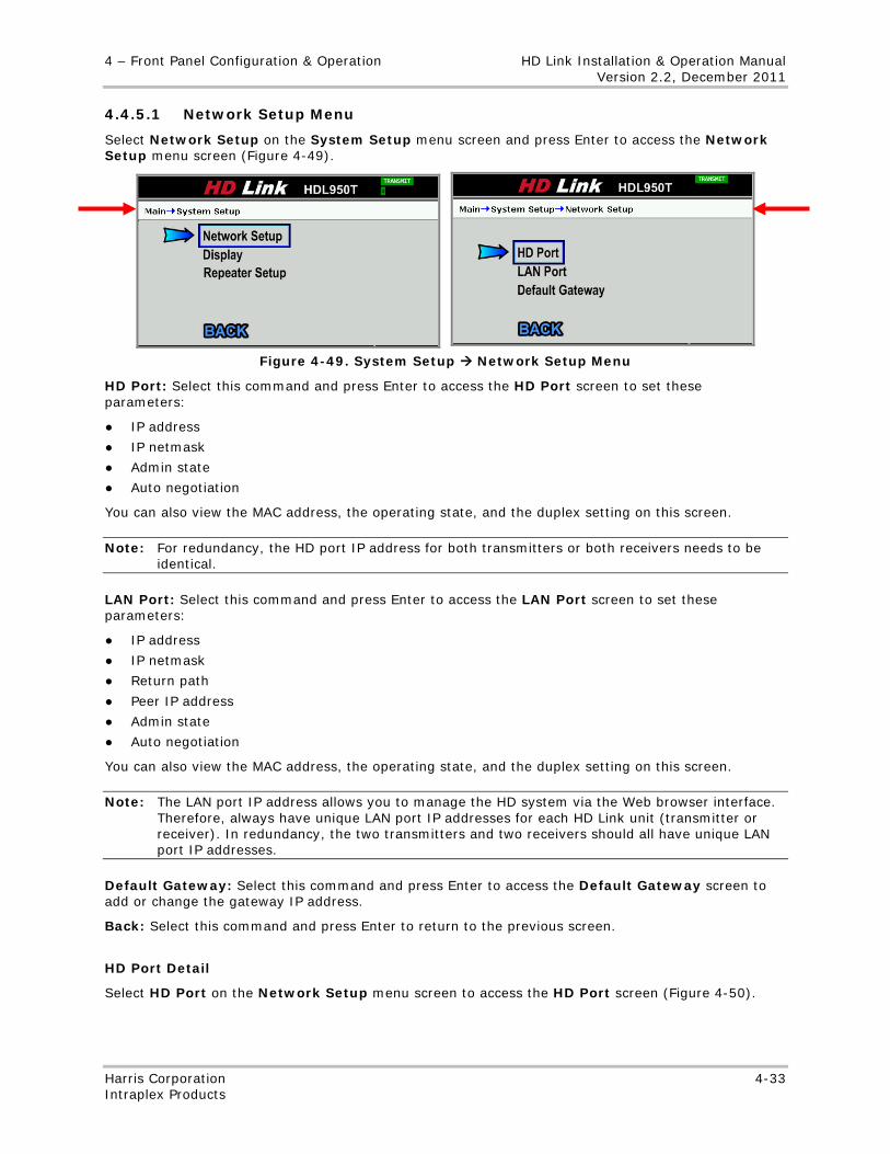
4 – Front Panel Configuration & Operation HD Link Installation & Operation Manual Version 2.2, December 2011
Harris Corporation 4-33 Intraplex Products
4.4.5.1 Network Setup Menu
Select Network Setup on the System Setup menu screen and press Enter to access the Network Setup menu screen (Figure 4-49).
Figure 4-49. System Setup Network Setup Menu
HD Port: Select this command and press Enter to access the HD Port screen to set these parameters:
● IP address
● IP netmask
● Admin state
● Auto negotiation
You can also view the MAC address, the operating state, and the duplex setting on this screen.
Note: For redundancy, the HD port IP address for both transmitters or both receivers needs to be identical.
LAN Port: Select this command and press Enter to access the LAN Port screen to set these parameters:
● IP address
● IP netmask
● Return path
● Peer IP address
● Admin state
● Auto negotiation
You can also view the MAC address, the operating state, and the duplex setting on this screen.
Note: The LAN port IP address allows you to manage the HD system via the Web browser interface. Therefore, always have unique LAN port IP addresses for each HD Link unit (transmitter or receiver). In redundancy, the two transmitters and two receivers should all have unique LAN port IP addresses.
Default Gateway: Select this command and press Enter to access the Default Gateway screen to add or change the gateway IP address.
Back: Select this command and press Enter to return to the previous screen.
HD Port Detail
Select HD Port on the Network Setup menu screen to access the HD Port screen (Figure 4-50).
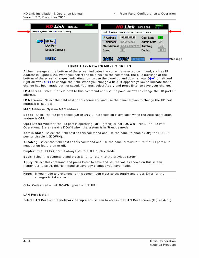
HD Link Installation & Operation Manual 4 – Front Panel Configuration & Operation Version 2.2, December 2011
4-34 Harris Corporation Intraplex Products
Figure 4-50. Network Setup HD Port
A blue message at the bottom of the screen indicates the currently selected command, such as IP Address in Figure 4-24. When you select the field next to the command, the blue message at the bottom of the screen changes, indicating how to use the panel up and down arrows () or left and right arrows () to change the field. When you change a field, it appears yellow to indicate that a change has been made but not saved. You must select Apply and press Enter to save your change.
IP Address: Select the field next to this command and use the panel arrows to change the HD port IP address.
IP Netmask: Select the field next to this command and use the panel arrows to change the HD port netmask IP address.
MAC Address: System MAC address.
Speed: Select the HD port speed (10 or 100). This selection is available when the Auto Negotiation feature is OFF.
Oper State: Whether the HD port is operating (UP - green) or not (DOWN - red). The HD Port Operational State remains DOWN when the system is in Standby mode.
Admin State: Select the field next to this command and use the panel to enable (UP) the HD E2X port or disable it (DOWN).
AutoNeg: Select the field next to this command and use the panel arrows to turn the HD port auto negotiation feature on or off.
Duplex: The HD E2X port is always set to FULL duplex mode.
Back: Select this command and press Enter to return to the previous screen.
Apply: Select this command and press Enter to save and set the values shown on this screen. Remember to select this command to save any changes you have made.
Note: If you made any changes to this screen, you must select Apply and press Enter for the changes to take effect.
Color Codes: red = link DOWN; green = link UP.
LAN Port Detail
Select LAN Port on the Network Setup menu screen to access the LAN Port screen (Figure 4-51).
Message
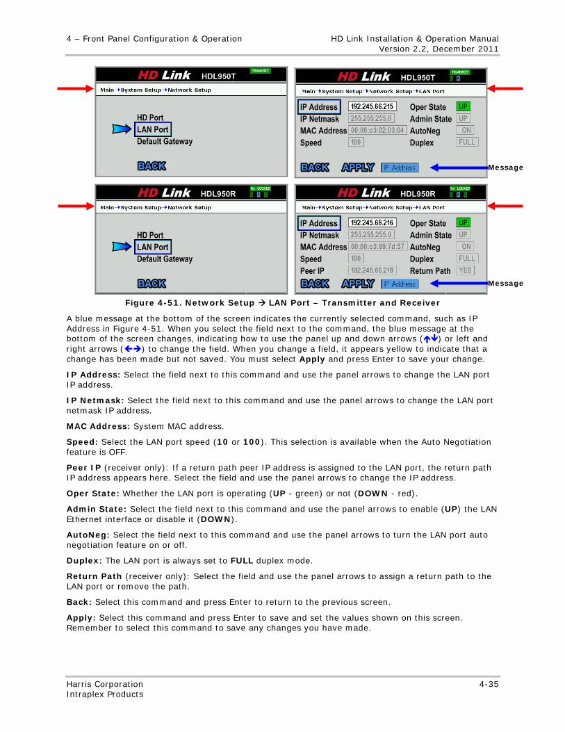
4 – Front Panel Configuration & Operation HD Link Installation & Operation Manual Version 2.2, December 2011
Harris Corporation 4-35 Intraplex Products
Figure 4-51. Network Setup LAN Port – Transmitter and Receiver
A blue message at the bottom of the screen indicates the currently selected command, such as IP Address in Figure 4-51. When you select the field next to the command, the blue message at the bottom of the screen changes, indicating how to use the panel up and down arrows () or left and right arrows () to change the field. When you change a field, it appears yellow to indicate that a change has been made but not saved. You must select Apply and press Enter to save your change.
IP Address: Select the field next to this command and use the panel arrows to change the LAN port IP address.
IP Netmask: Select the field next to this command and use the panel arrows to change the LAN port netmask IP address.
MAC Address: System MAC address.
Speed: Select the LAN port speed (10 or 100). This selection is available when the Auto Negotiation feature is OFF.
Peer IP (receiver only): If a return path peer IP address is assigned to the LAN port, the return path IP address appears here. Select the field and use the panel arrows to change the IP address.
Oper State: Whether the LAN port is operating (UP - green) or not (DOWN - red).
Admin State: Select the field next to this command and use the panel arrows to enable (UP) the LAN Ethernet interface or disable it (DOWN).
AutoNeg: Select the field next to this command and use the panel arrows to turn the LAN port auto negotiation feature on or off.
Duplex: The LAN port is always set to FULL duplex mode.
Return Path (receiver only): Select the field and use the panel arrows to assign a return path to the LAN port or remove the path.
Back: Select this command and press Enter to return to the previous screen.
Apply: Select this command and press Enter to save and set the values shown on this screen. Remember to select this command to save any changes you have made.
Message
Message
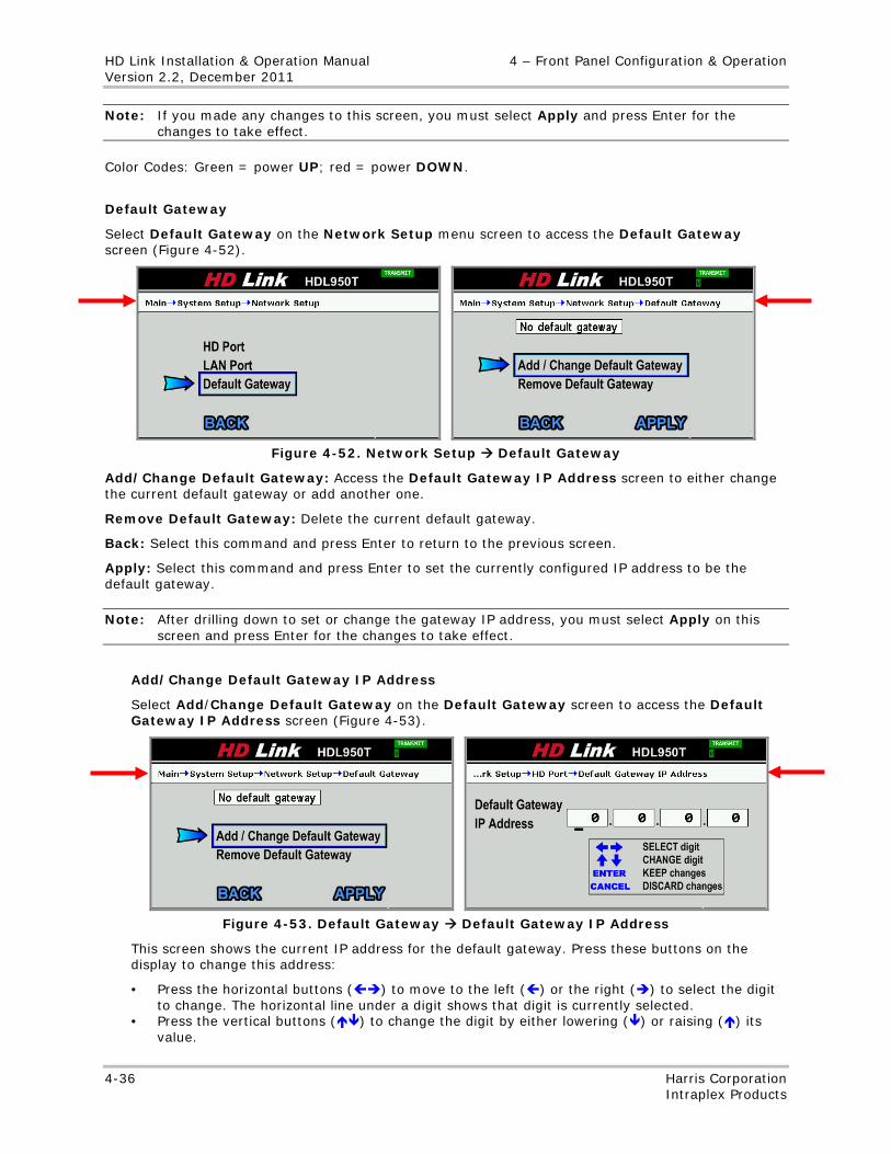
HD Link Installation & Operation Manual 4 – Front Panel Configuration & Operation Version 2.2, December 2011
4-36 Harris Corporation Intraplex Products
Note: If you made any changes to this screen, you must select Apply and press Enter for the changes to take effect.
Color Codes: Green = power UP; red = power DOWN.
Default Gateway
Select Default Gateway on the Network Setup menu screen to access the Default Gateway screen (Figure 4-52).
Figure 4-52. Network Setup Default Gateway
Add/Change Default Gateway: Access the Default Gateway IP Address screen to either change the current default gateway or add another one.
Remove Default Gateway: Delete the current default gateway.
Back: Select this command and press Enter to return to the previous screen.
Apply: Select this command and press Enter to set the currently configured IP address to be the default gateway.
Note: After drilling down to set or change the gateway IP address, you must select Apply on this screen and press Enter for the changes to take effect.
Add/Change Default Gateway IP Address
Select Add/Change Default Gateway on the Default Gateway screen to access the Default Gateway IP Address screen (Figure 4-53).
Figure 4-53. Default Gateway Default Gateway IP Address
This screen shows the current IP address for the default gateway. Press these buttons on the display to change this address:
• Press the horizontal buttons () to move to the left () or the right () to select the digit to change. The horizontal line under a digit shows that digit is currently selected.
• Press the vertical buttons () to change the digit by either lowering () or raising () its value.
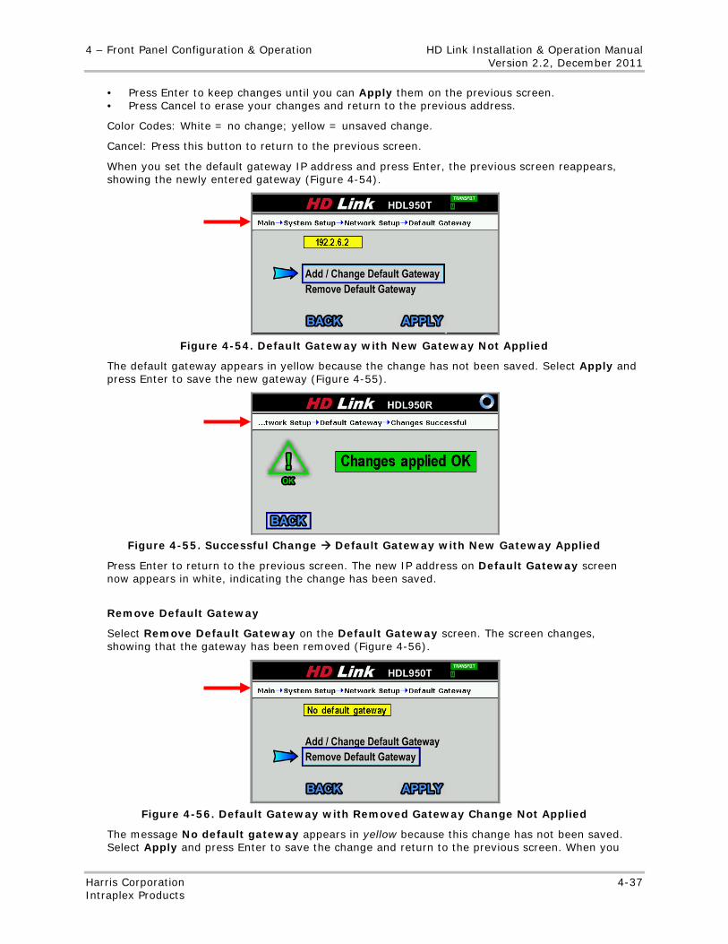
4 – Front Panel Configuration & Operation HD Link Installation & Operation Manual Version 2.2, December 2011
Harris Corporation 4-37 Intraplex Products
• Press Enter to keep changes until you can Apply them on the previous screen. • Press Cancel to erase your changes and return to the previous address.
Color Codes: White = no change; yellow = unsaved change.
Cancel: Press this button to return to the previous screen.
When you set the default gateway IP address and press Enter, the previous screen reappears, showing the newly entered gateway (Figure 4-54).
Figure 4-54. Default Gateway with New Gateway Not Applied
The default gateway appears in yellow because the change has not been saved. Select Apply and press Enter to save the new gateway (Figure 4-55).
Figure 4-55. Successful Change Default Gateway with New Gateway Applied
Press Enter to return to the previous screen. The new IP address on Default Gateway screen now appears in white, indicating the change has been saved.
Remove Default Gateway
Select Remove Default Gateway on the Default Gateway screen. The screen changes, showing that the gateway has been removed (Figure 4-56).
Figure 4-56. Default Gateway with Removed Gateway Change Not Applied
The message No default gateway appears in yellow because this change has not been saved. Select Apply and press Enter to save the change and return to the previous screen. When you
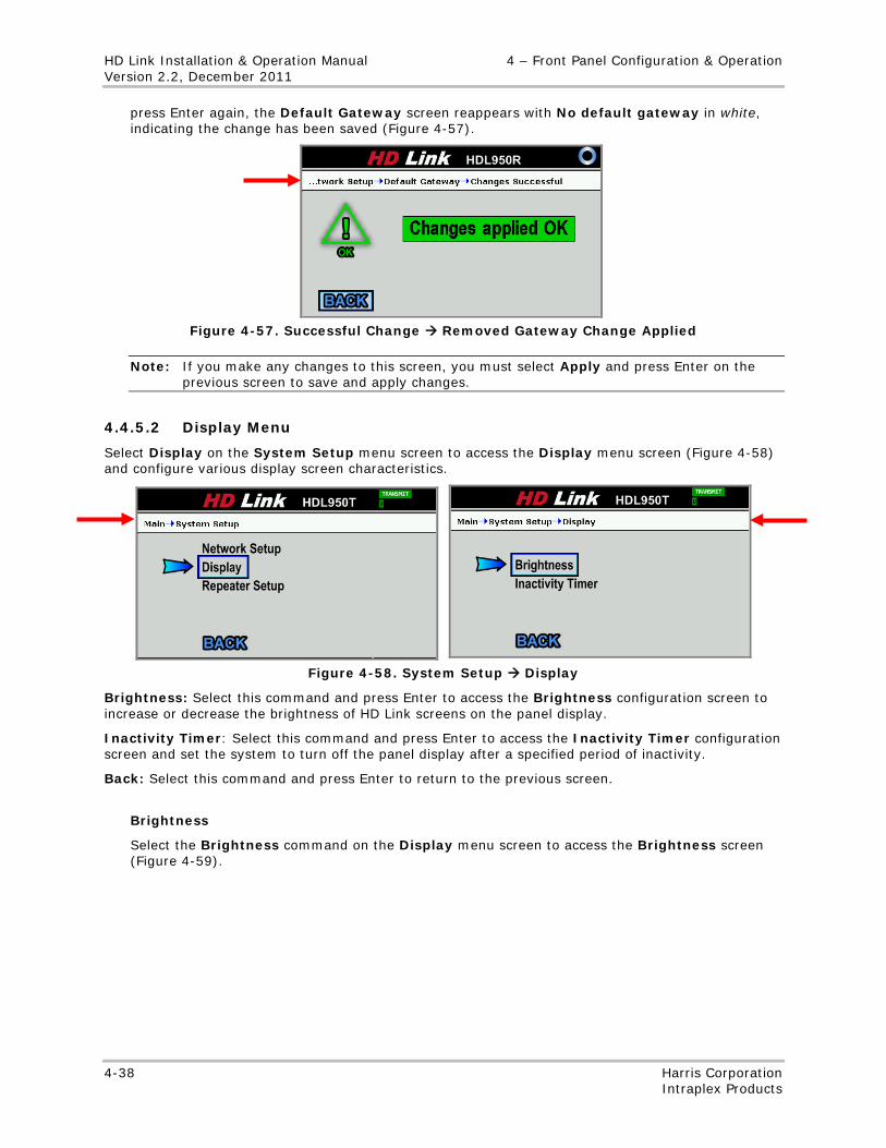
HD Link Installation & Operation Manual 4 – Front Panel Configuration & Operation Version 2.2, December 2011
4-38 Harris Corporation Intraplex Products
press Enter again, the Default Gateway screen reappears with No default gateway in white, indicating the change has been saved (Figure 4-57).
Figure 4-57. Successful Change Removed Gateway Change Applied
Note: If you make any changes to this screen, you must select Apply and press Enter on the previous screen to save and apply changes.
4.4.5.2 Display Menu
Select Display on the System Setup menu screen to access the Display menu screen (Figure 4-58) and configure various display screen characteristics.
Figure 4-58. System Setup Display
Brightness: Select this command and press Enter to access the Brightness configuration screen to increase or decrease the brightness of HD Link screens on the panel display.
Inactivity Timer: Select this command and press Enter to access the Inactivity Timer configuration screen and set the system to turn off the panel display after a specified period of inactivity.
Back: Select this command and press Enter to return to the previous screen.
Brightness
Select the Brightness command on the Display menu screen to access the Brightness screen (Figure 4-59).
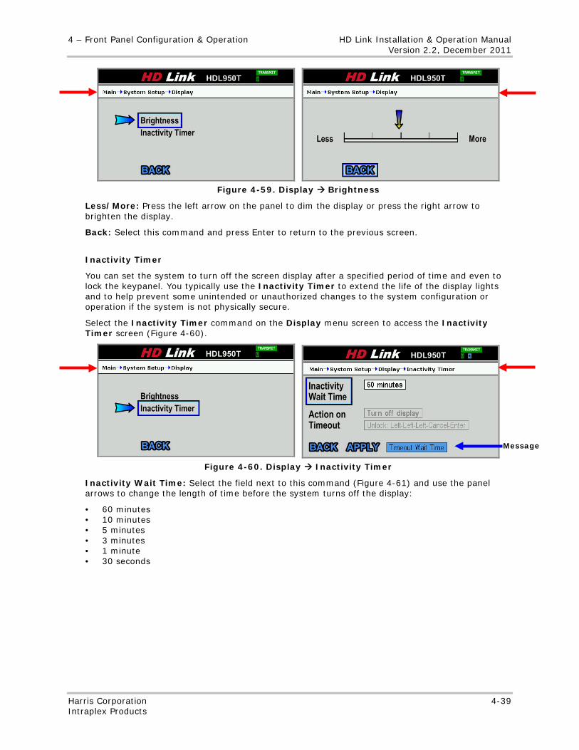
4 – Front Panel Configuration & Operation HD Link Installation & Operation Manual Version 2.2, December 2011
Harris Corporation 4-39 Intraplex Products
Figure 4-59. Display Brightness
Less/More: Press the left arrow on the panel to dim the display or press the right arrow to brighten the display.
Back: Select this command and press Enter to return to the previous screen.
Inactivity Timer
You can set the system to turn off the screen display after a specified period of time and even to lock the keypanel. You typically use the Inactivity Timer to extend the life of the display lights and to help prevent some unintended or unauthorized changes to the system configuration or operation if the system is not physically secure.
Select the Inactivity Timer command on the Display menu screen to access the Inactivity Timer screen (Figure 4-60).
Figure 4-60. Display Inactivity Timer
Inactivity Wait Time: Select the field next to this command (Figure 4-61) and use the panel arrows to change the length of time before the system turns off the display:
• 60 minutes • 10 minutes • 5 minutes • 3 minutes • 1 minute • 30 seconds
Message
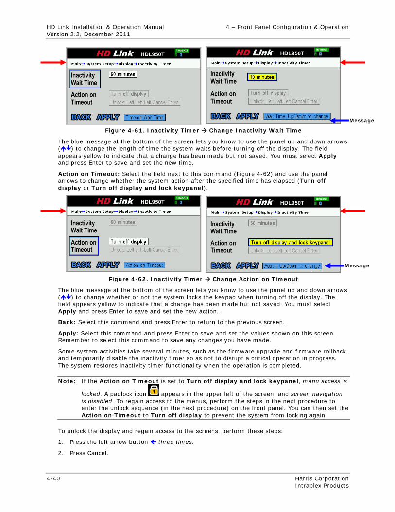
HD Link Installation & Operation Manual 4 – Front Panel Configuration & Operation Version 2.2, December 2011
4-40 Harris Corporation Intraplex Products
Figure 4-61. Inactivity Timer Change Inactivity Wait Time
The blue message at the bottom of the screen lets you know to use the panel up and down arrows () to change the length of time the system waits before turning off the display. The field appears yellow to indicate that a change has been made but not saved. You must select Apply and press Enter to save and set the new time.
Action on Timeout: Select the field next to this command (Figure 4-62) and use the panel arrows to change whether the system action after the specified time has elapsed (Turn off display or Turn off display and lock keypanel).
Figure 4-62. Inactivity Timer Change Action on Timeout
The blue message at the bottom of the screen lets you know to use the panel up and down arrows () to change whether or not the system locks the keypad when turning off the display. The field appears yellow to indicate that a change has been made but not saved. You must select Apply and press Enter to save and set the new action.
Back: Select this command and press Enter to return to the previous screen.
Apply: Select this command and press Enter to save and set the values shown on this screen. Remember to select this command to save any changes you have made.
Some system activities take several minutes, such as the firmware upgrade and firmware rollback, and temporarily disable the inactivity timer so as not to disrupt a critical operation in progress. The system restores inactivity timer functionality when the operation is completed.
Note: If the Action on Timeout is set to Turn off display and lock keypanel, menu access is
locked. A padlock icon appears in the upper left of the screen, and screen navigation is disabled. To regain access to the menus, perform the steps in the next procedure to enter the unlock sequence (in the next procedure) on the front panel. You can then set the Action on Timeout to Turn off display to prevent the system from locking again.
To unlock the display and regain access to the screens, perform these steps:
1. Press the left arrow button three times.
2. Press Cancel.
Message
Message
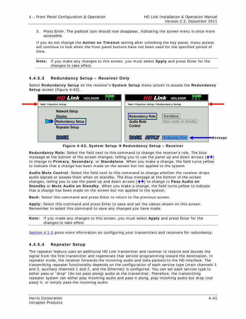
4 – Front Panel Configuration & Operation HD Link Installation & Operation Manual Version 2.2, December 2011
Harris Corporation 4-41 Intraplex Products
3. Press Enter. The padlock icon should now disappear, indicating the screen menu is once more accessible.
If you do not change the Action on Timeout setting after unlocking the key panel, menu access will continue to lock when the front panel buttons have not been used for the specified period of time.
Note: If you make any changes to this screen, you must select Apply and press Enter for the changes to take effect.
4.4.5.3 Redundancy Setup – Receiver Only
Select Redundancy Setup on the receiver’s System Setup menu screen to access the Redundancy Setup screen (Figure 4-63).
Figure 4-63. System Setup Redundancy Setup – Receiver
Redundancy Role: Select the field next to this command to change the receiver’s role. The blue message at the bottom of the screen changes, telling you to use the panel up and down arrows () to change to Primary, Secondary, or Standalone. When you make a change, the field turns yellow to indicate that a change has been made on the screen but not applied to the system.
Audio Mute Control: Select the field next to this command to change whether the receiver drops audio signals or passes them when on standby. The blue message at the bottom of the screen changes, telling you to use the panel up and down arrows () to change to Pass Audio on Standby or Mute Audio on Standby. When you make a change, the field turns yellow to indicate that a change has been made on the screen but not applied to the system.
Back: Select this command and press Enter to return to the previous screen.
Apply: Select this command and press Enter to save and set the values shown on this screen. Remember to select this command to save any changes you have made.
Note: If you made any changes to this screen, you must select Apply and press Enter for the changes to take effect.
Section 4.1.6 gives more information on configuring your transmitters and receivers for redundancy.
4.4.5.4 Repeater Setup
The repeater feature uses an additional HD Link transmitter and receiver to receive and decode the signal from the first transmitter and regenerate that service programming toward the destination. In repeater mode, the receiver forwards the incoming audio and data packets to the HD interface. The transmitting repeater functionality depends on the configuration of each service type (main channels 1 and 2, auxiliary channels 1 and 2, and the Ethernet) is configured. You can set each service type to either pass or “drop” (do not pass along) audio at the transmitter. Therefore, the transmitting repeater system can either play incoming audio and pass it along, play incoming audio but drop (not pass) it, or simply pass the incoming audio.
Message
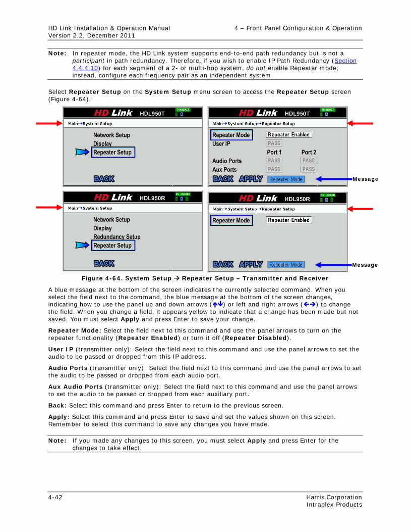
HD Link Installation & Operation Manual 4 – Front Panel Configuration & Operation Version 2.2, December 2011
4-42 Harris Corporation Intraplex Products
Note: In repeater mode, the HD Link system supports end-to-end path redundancy but is not a participant in path redundancy. Therefore, if you wish to enable IP Path Redundancy (Section 4.4.4.10) for each segment of a 2- or multi-hop system, do not enable Repeater mode; instead, configure each frequency pair as an independent system.
Select Repeater Setup on the System Setup menu screen to access the Repeater Setup screen (Figure 4-64).
Figure 4-64. System Setup Repeater Setup – Transmitter and Receiver
A blue message at the bottom of the screen indicates the currently selected command. When you select the field next to the command, the blue message at the bottom of the screen changes, indicating how to use the panel up and down arrows () or left and right arrows () to change the field. When you change a field, it appears yellow to indicate that a change has been made but not saved. You must select Apply and press Enter to save your change.
Repeater Mode: Select the field next to this command and use the panel arrows to turn on the repeater functionality (Repeater Enabled) or turn it off (Repeater Disabled).
User IP (transmitter only): Select the field next to this command and use the panel arrows to set the audio to be passed or dropped from this IP address.
Audio Ports (transmitter only): Select the field next to this command and use the panel arrows to set the audio to be passed or dropped from each audio port.
Aux Audio Ports (transmitter only): Select the field next to this command and use the panel arrows to set the audio to be passed or dropped from each auxiliary port.
Back: Select this command and press Enter to return to the previous screen.
Apply: Select this command and press Enter to save and set the values shown on this screen. Remember to select this command to save any changes you have made.
Note: If you made any changes to this screen, you must select Apply and press Enter for the changes to take effect.
Message
Message
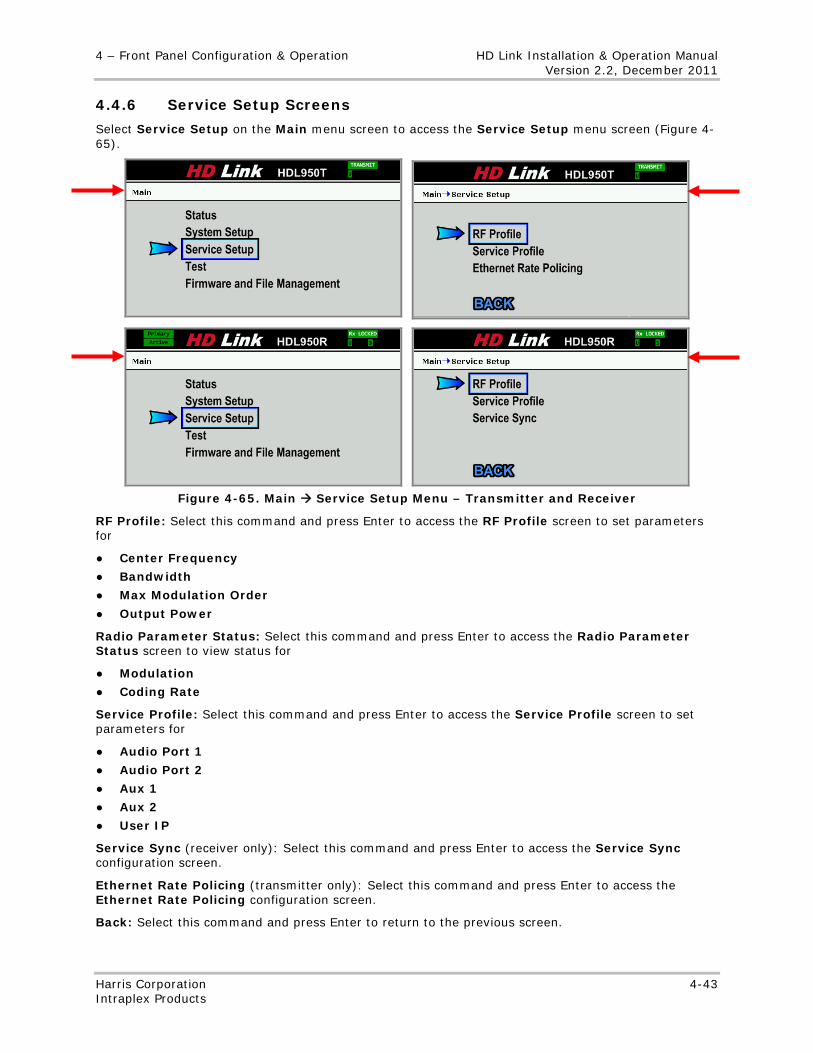
4 – Front Panel Configuration & Operation HD Link Installation & Operation Manual Version 2.2, December 2011
Harris Corporation 4-43 Intraplex Products
4.4.6 Service Setup Screens
Select Service Setup on the Main menu screen to access the Service Setup menu screen (Figure 4-65).
Figure 4-65. Main Service Setup Menu – Transmitter and Receiver
RF Profile: Select this command and press Enter to access the RF Profile screen to set parameters for
● Center Frequency
● Bandwidth
● Max Modulation Order
● Output Power
Radio Parameter Status: Select this command and press Enter to access the Radio Parameter Status screen to view status for
● Modulation
● Coding Rate
Service Profile: Select this command and press Enter to access the Service Profile screen to set parameters for
● Audio Port 1
● Audio Port 2
● Aux 1
● Aux 2
● User IP
Service Sync (receiver only): Select this command and press Enter to access the Service Sync configuration screen.
Ethernet Rate Policing (transmitter only): Select this command and press Enter to access the Ethernet Rate Policing configuration screen.
Back: Select this command and press Enter to return to the previous screen.
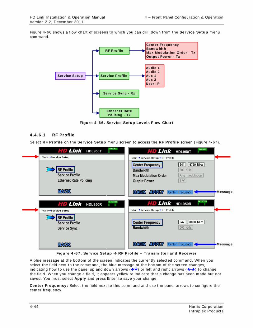
HD Link Installation & Operation Manual 4 – Front Panel Configuration & Operation Version 2.2, December 2011
4-44 Harris Corporation Intraplex Products
Figure 4-66 shows a flow chart of screens to which you can drill down from the Service Setup menu command.
RF Profile
Service Profile
Center FrequencyBandwidthMax Modulation Order - TxOutput Power - Tx
Audio 1Audio 2Aux 1Aux 2User IP
Service Setup
Service Sync - Rx
Ethernet Rate Policing - Tx
Figure 4-66. Service Setup Levels Flow Chart
4.4.6.1 RF Profile
Select RF Profile on the Service Setup menu screen to access the RF Profile screen (Figure 4-67).
Figure 4-67. Service Setup RF Profile – Transmitter and Receiver
A blue message at the bottom of the screen indicates the currently selected command. When you select the field next to the command, the blue message at the bottom of the screen changes, indicating how to use the panel up and down arrows () or left and right arrows () to change the field. When you change a field, it appears yellow to indicate that a change has been made but not saved. You must select Apply and press Enter to save your change.
Center Frequency: Select the field next to this command and use the panel arrows to configure the center frequency.
Message
Message
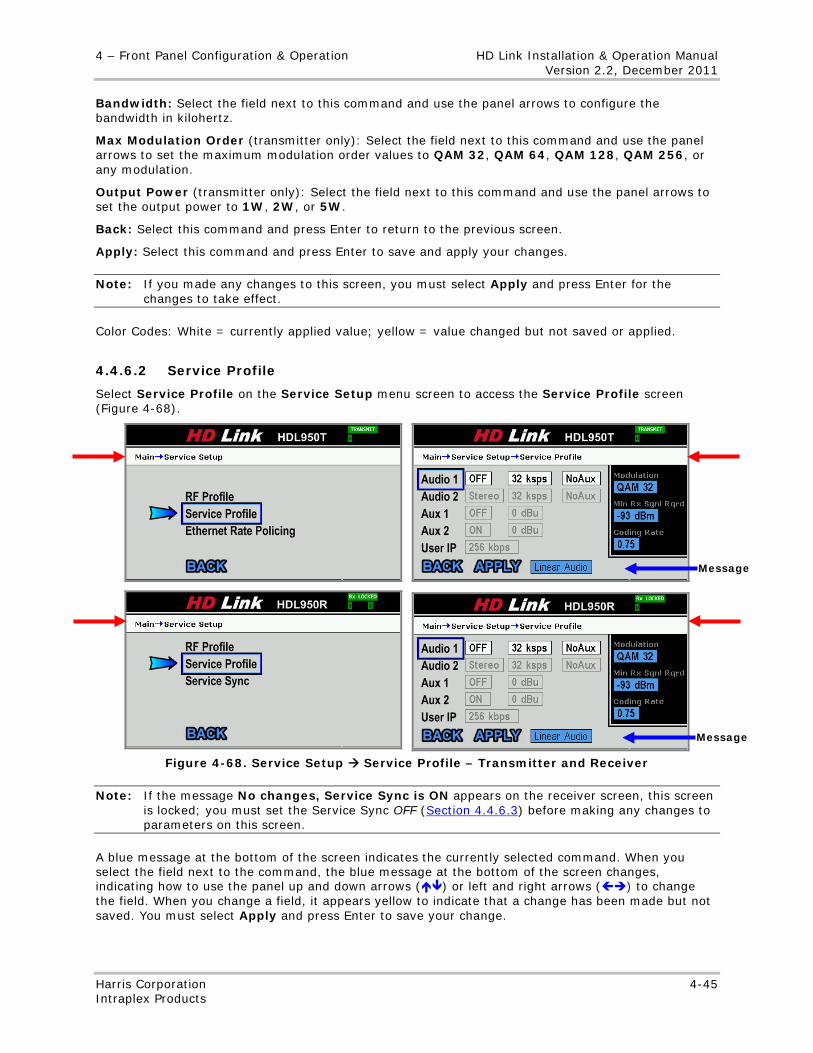
4 – Front Panel Configuration & Operation HD Link Installation & Operation Manual Version 2.2, December 2011
Harris Corporation 4-45 Intraplex Products
Bandwidth: Select the field next to this command and use the panel arrows to configure the bandwidth in kilohertz.
Max Modulation Order (transmitter only): Select the field next to this command and use the panel arrows to set the maximum modulation order values to QAM 32, QAM 64, QAM 128, QAM 256, or any modulation.
Output Power (transmitter only): Select the field next to this command and use the panel arrows to set the output power to 1W, 2W, or 5W.
Back: Select this command and press Enter to return to the previous screen.
Apply: Select this command and press Enter to save and apply your changes.
Note: If you made any changes to this screen, you must select Apply and press Enter for the changes to take effect.
Color Codes: White = currently applied value; yellow = value changed but not saved or applied.
4.4.6.2 Service Profile
Select Service Profile on the Service Setup menu screen to access the Service Profile screen (Figure 4-68).
Figure 4-68. Service Setup Service Profile – Transmitter and Receiver
Note: If the message No changes, Service Sync is ON appears on the receiver screen, this screen is locked; you must set the Service Sync OFF (Section 4.4.6.3) before making any changes to parameters on this screen.
A blue message at the bottom of the screen indicates the currently selected command. When you select the field next to the command, the blue message at the bottom of the screen changes, indicating how to use the panel up and down arrows () or left and right arrows () to change the field. When you change a field, it appears yellow to indicate that a change has been made but not saved. You must select Apply and press Enter to save your change.
Message
Message
HD Link Installation & Operation Manual 4 – Front Panel Configuration & Operation Version 2.2, December 2011
4-46 Harris Corporation Intraplex Products
Audio 1: Select Audio 1 and then use the panel left or right arrow () to select a parameter field to change on the Audio 1 row:
● Left field – Use the panel arrows to change the Port Mode to one of these options:
• Mono • Stereo • Off
● Middle field – Use the panel arrows to change the Sample Rate to one of these rates:
• 16 ksps (compressed only) • 24 ksps (compressed only) • 32 ksps (linear or compressed) • 44.1 ksps (linear or compressed) • 48 ksps (linear or compressed)
Note: For linear audio ports, you can set the sample rate to 32 ksps, 44.1 ksps, or 48 ksps. For compressed audio ports, you can set the sample rate to 16 ksps, 24 ksps, 32 ksps, 44.1 ksps, or 48 ksps.
● Right field – For linear audio, use the panel arrows to enable (Aux) or disable (No Aux) the auxiliary data feature. For compressed audio, use the panel arrows to select word length (16, 20, or 24 spaces).
Audio 2: Select Audio 2 and then use the panel left or right arrow () to select a parameter field to change on the Audio 2 row:
● Left field – Use the panel arrows to change the Port Mode to one of these options:
• Mono • Stereo • Off
● Middle field – Use the panel arrows to change the Sample Rate to one of these rates:
• 16 ksps (compressed only) • 24 ksps (compressed only) • 32 ksps (linear or compressed) • 44.1 ksps (linear or compressed) • 48 ksps (linear or compressed)
Note: For linear audio ports, you can set the sample rate to 32 ksps, 44.1 ksps, or 48 ksps. For compressed audio ports, you can set the sample rate to 16 ksps, 24 ksps, 32 ksps, 44.1 ksps, or 48 ksps.
● For linear audio, use the panel arrows to enable (Aux) or disable (No Aux) the auxiliary data feature. For compressed audio, use the panel arrows to select word length (16, 20, or 24 spaces).
Aux 1: Select Aux 1 and then use the panel arrows to select a parameter field to change on the Aux 1 row:
● ON or OFF
● Attenuation – in dBu
Aux 2: Select Aux 2 and then use the panel arrows to select a parameter field to change on the Aux 2 row:
● ON or OFF
● Attenuation – in dBu
User IP: Select User IP and then use the panel arrows to change the STL Ethernet rate to None (off) or one of these rates:
● 128 kbps
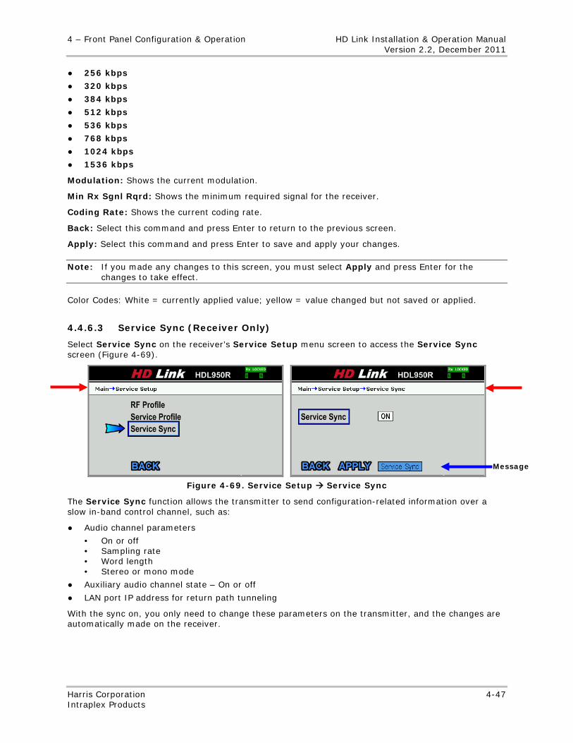
4 – Front Panel Configuration & Operation HD Link Installation & Operation Manual Version 2.2, December 2011
Harris Corporation 4-47 Intraplex Products
● 256 kbps
● 320 kbps
● 384 kbps
● 512 kbps
● 536 kbps
● 768 kbps
● 1024 kbps
● 1536 kbps
Modulation: Shows the current modulation.
Min Rx Sgnl Rqrd: Shows the minimum required signal for the receiver.
Coding Rate: Shows the current coding rate.
Back: Select this command and press Enter to return to the previous screen.
Apply: Select this command and press Enter to save and apply your changes.
Note: If you made any changes to this screen, you must select Apply and press Enter for the changes to take effect.
Color Codes: White = currently applied value; yellow = value changed but not saved or applied.
4.4.6.3 Service Sync (Receiver Only)
Select Service Sync on the receiver’s Service Setup menu screen to access the Service Sync screen (Figure 4-69).
Figure 4-69. Service Setup Service Sync
The Service Sync function allows the transmitter to send configuration-related information over a slow in-band control channel, such as:
● Audio channel parameters
• On or off • Sampling rate • Word length • Stereo or mono mode
● Auxiliary audio channel state – On or off
● LAN port IP address for return path tunneling
With the sync on, you only need to change these parameters on the transmitter, and the changes are automatically made on the receiver.
Message
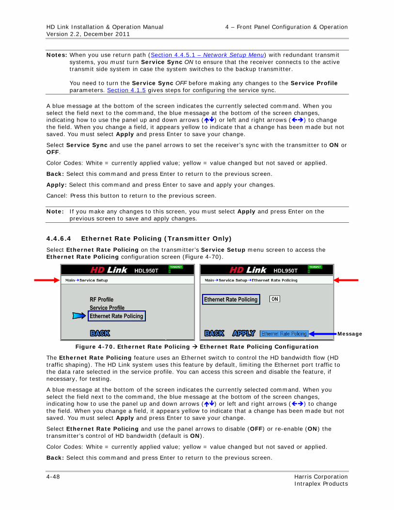
HD Link Installation & Operation Manual 4 – Front Panel Configuration & Operation Version 2.2, December 2011
4-48 Harris Corporation Intraplex Products
Notes: When you use return path (Section 4.4.5.1 – Network Setup Menu) with redundant transmit systems, you must turn Service Sync ON to ensure that the receiver connects to the active transmit side system in case the system switches to the backup transmitter. You need to turn the Service Sync OFF before making any changes to the Service Profile parameters. Section 4.1.5 gives steps for configuring the service sync.
A blue message at the bottom of the screen indicates the currently selected command. When you select the field next to the command, the blue message at the bottom of the screen changes, indicating how to use the panel up and down arrows () or left and right arrows () to change the field. When you change a field, it appears yellow to indicate that a change has been made but not saved. You must select Apply and press Enter to save your change.
Select Service Sync and use the panel arrows to set the receiver’s sync with the transmitter to ON or OFF.
Color Codes: White = currently applied value; yellow = value changed but not saved or applied.
Back: Select this command and press Enter to return to the previous screen.
Apply: Select this command and press Enter to save and apply your changes.
Cancel: Press this button to return to the previous screen.
Note: If you make any changes to this screen, you must select Apply and press Enter on the previous screen to save and apply changes.
4.4.6.4 Ethernet Rate Policing (Transmitter Only)
Select Ethernet Rate Policing on the transmitter’s Service Setup menu screen to access the Ethernet Rate Policing configuration screen (Figure 4-70).
Figure 4-70. Ethernet Rate Policing Ethernet Rate Policing Configuration
The Ethernet Rate Policing feature uses an Ethernet switch to control the HD bandwidth flow (HD traffic shaping). The HD Link system uses this feature by default, limiting the Ethernet port traffic to the data rate selected in the service profile. You can access this screen and disable the feature, if necessary, for testing.
A blue message at the bottom of the screen indicates the currently selected command. When you select the field next to the command, the blue message at the bottom of the screen changes, indicating how to use the panel up and down arrows () or left and right arrows () to change the field. When you change a field, it appears yellow to indicate that a change has been made but not saved. You must select Apply and press Enter to save your change.
Select Ethernet Rate Policing and use the panel arrows to disable (OFF) or re-enable (ON) the transmitter’s control of HD bandwidth (default is ON).
Color Codes: White = currently applied value; yellow = value changed but not saved or applied.
Back: Select this command and press Enter to return to the previous screen.
Message
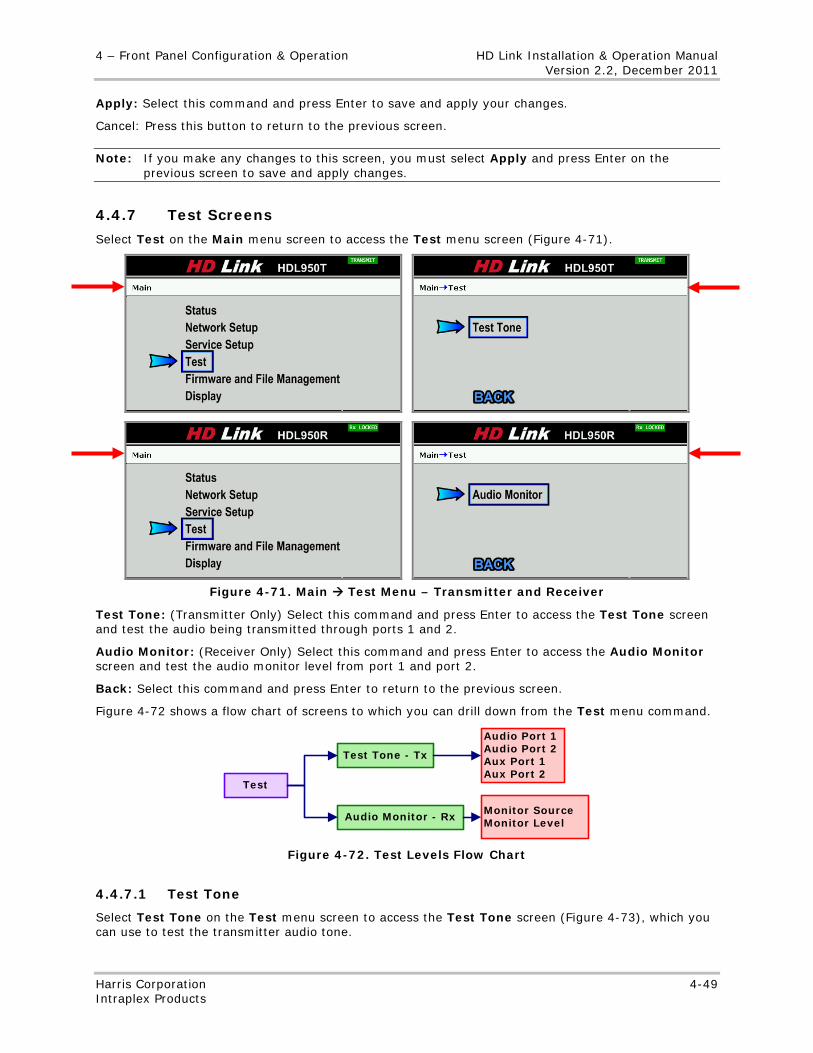
4 – Front Panel Configuration & Operation HD Link Installation & Operation Manual Version 2.2, December 2011
Harris Corporation 4-49 Intraplex Products
Apply: Select this command and press Enter to save and apply your changes.
Cancel: Press this button to return to the previous screen.
Note: If you make any changes to this screen, you must select Apply and press Enter on the previous screen to save and apply changes.
4.4.7 Test Screens
Select Test on the Main menu screen to access the Test menu screen (Figure 4-71).
Figure 4-71. Main Test Menu – Transmitter and Receiver
Test Tone: (Transmitter Only) Select this command and press Enter to access the Test Tone screen and test the audio being transmitted through ports 1 and 2.
Audio Monitor: (Receiver Only) Select this command and press Enter to access the Audio Monitor screen and test the audio monitor level from port 1 and port 2.
Back: Select this command and press Enter to return to the previous screen.
Figure 4-72 shows a flow chart of screens to which you can drill down from the Test menu command.
Test Tone - Tx
Audio Port 1Audio Port 2Aux Port 1Aux Port 2
Test
Audio Monitor - Rx Monitor SourceMonitor Level
Figure 4-72. Test Levels Flow Chart
4.4.7.1 Test Tone
Select Test Tone on the Test menu screen to access the Test Tone screen (Figure 4-73), which you can use to test the transmitter audio tone.
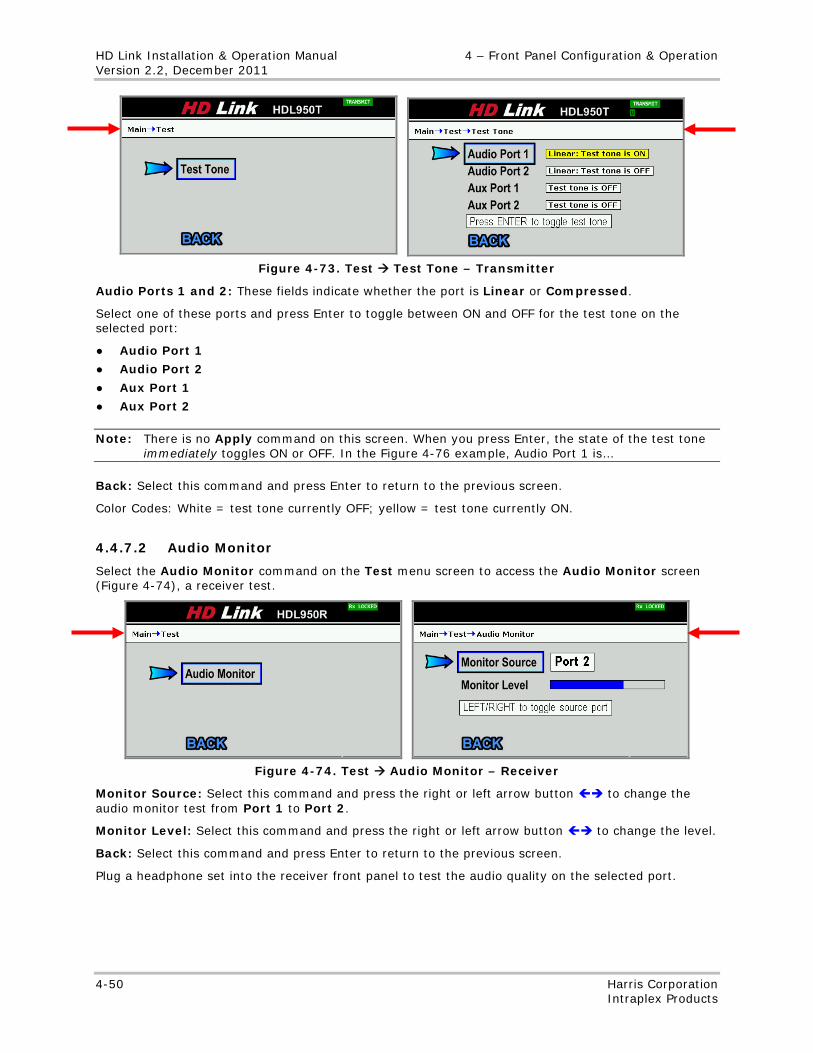
HD Link Installation & Operation Manual 4 – Front Panel Configuration & Operation Version 2.2, December 2011
4-50 Harris Corporation Intraplex Products
Figure 4-73. Test Test Tone – Transmitter
Audio Ports 1 and 2: These fields indicate whether the port is Linear or Compressed.
Select one of these ports and press Enter to toggle between ON and OFF for the test tone on the selected port:
● Audio Port 1
● Audio Port 2
● Aux Port 1
● Aux Port 2
Note: There is no Apply command on this screen. When you press Enter, the state of the test tone immediately toggles ON or OFF. In the Figure 4-76 example, Audio Port 1 is…
Back: Select this command and press Enter to return to the previous screen.
Color Codes: White = test tone currently OFF; yellow = test tone currently ON.
4.4.7.2 Audio Monitor
Select the Audio Monitor command on the Test menu screen to access the Audio Monitor screen (Figure 4-74), a receiver test.
Figure 4-74. Test Audio Monitor – Receiver
Monitor Source: Select this command and press the right or left arrow button to change the audio monitor test from Port 1 to Port 2.
Monitor Level: Select this command and press the right or left arrow button to change the level.
Back: Select this command and press Enter to return to the previous screen.
Plug a headphone set into the receiver front panel to test the audio quality on the selected port.
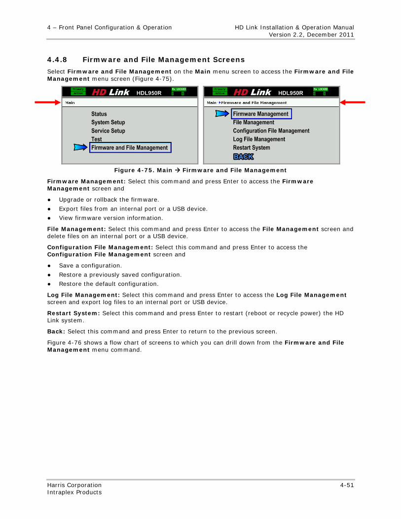
4 – Front Panel Configuration & Operation HD Link Installation & Operation Manual Version 2.2, December 2011
Harris Corporation 4-51 Intraplex Products
4.4.8 Firmware and File Management Screens
Select Firmware and File Management on the Main menu screen to access the Firmware and File Management menu screen (Figure 4-75).
Figure 4-75. Main Firmware and File Management
Firmware Management: Select this command and press Enter to access the Firmware Management screen and
● Upgrade or rollback the firmware.
● Export files from an internal port or a USB device.
● View firmware version information.
File Management: Select this command and press Enter to access the File Management screen and delete files on an internal port or a USB device.
Configuration File Management: Select this command and press Enter to access the Configuration File Management screen and
● Save a configuration.
● Restore a previously saved configuration.
● Restore the default configuration.
Log File Management: Select this command and press Enter to access the Log File Management screen and export log files to an internal port or USB device.
Restart System: Select this command and press Enter to restart (reboot or recycle power) the HD Link system.
Back: Select this command and press Enter to return to the previous screen.
Figure 4-76 shows a flow chart of screens to which you can drill down from the Firmware and File Management menu command.
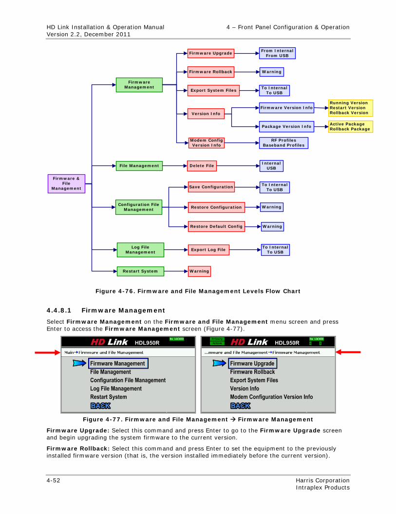
HD Link Installation & Operation Manual 4 – Front Panel Configuration & Operation Version 2.2, December 2011
4-52 Harris Corporation Intraplex Products
File Management
Firmware Management
Configuration File Management
Log File Management
Restart System
Firmware Upgrade
Firmware Rollback
Export System Files
Version Info
Delete File
Restore Configuration
Export Log File
Warning
From InternalFrom USB
Firmware & File
Management
Firmware Version Info
Save Configuration
Restore Default Config
Warning
Warning
To InternalTo USB
InternalUSB
To InternalTo USB
To InternalTo USB
Modem Config Version Info
RF ProfilesBaseband Profiles
Warning
Running VersionRestart VersionRollback Version
Package Version Info Active PackageRollback Package
Figure 4-76. Firmware and File Management Levels Flow Chart
4.4.8.1 Firmware Management
Select Firmware Management on the Firmware and File Management menu screen and press Enter to access the Firmware Management screen (Figure 4-77).
Figure 4-77. Firmware and File Management Firmware Management
Firmware Upgrade: Select this command and press Enter to go to the Firmware Upgrade screen and begin upgrading the system firmware to the current version.
Firmware Rollback: Select this command and press Enter to set the equipment to the previously installed firmware version (that is, the version installed immediately before the current version).
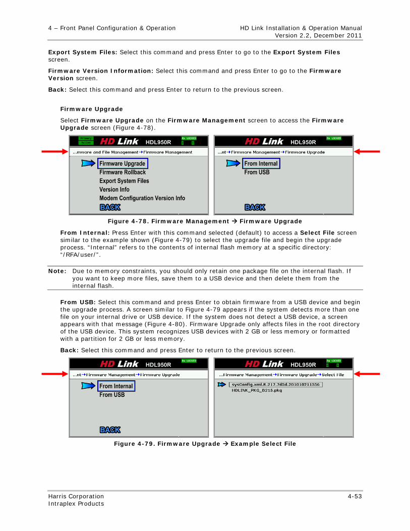
4 – Front Panel Configuration & Operation HD Link Installation & Operation Manual Version 2.2, December 2011
Harris Corporation 4-53 Intraplex Products
Export System Files: Select this command and press Enter to go to the Export System Files screen.
Firmware Version Information: Select this command and press Enter to go to the Firmware Version screen.
Back: Select this command and press Enter to return to the previous screen.
Firmware Upgrade
Select Firmware Upgrade on the Firmware Management screen to access the Firmware Upgrade screen (Figure 4-78).
Figure 4-78. Firmware Management Firmware Upgrade
From Internal: Press Enter with this command selected (default) to access a Select File screen similar to the example shown (Figure 4-79) to select the upgrade file and begin the upgrade process. “Internal” refers to the contents of internal flash memory at a specific directory: “/RFA/user/”.
Note: Due to memory constraints, you should only retain one package file on the internal flash. If you want to keep more files, save them to a USB device and then delete them from the internal flash.
From USB: Select this command and press Enter to obtain firmware from a USB device and begin the upgrade process. A screen similar to Figure 4-79 appears if the system detects more than one file on your internal drive or USB device. If the system does not detect a USB device, a screen appears with that message (Figure 4-80). Firmware Upgrade only affects files in the root directory of the USB device. This system recognizes USB devices with 2 GB or less memory or formatted with a partition for 2 GB or less memory.
Back: Select this command and press Enter to return to the previous screen.
Figure 4-79. Firmware Upgrade Example Select File
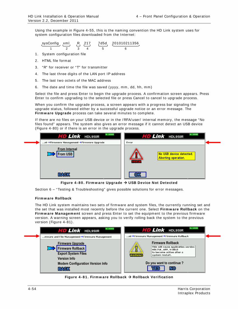
HD Link Installation & Operation Manual 4 – Front Panel Configuration & Operation Version 2.2, December 2011
4-54 Harris Corporation Intraplex Products
Using the example in Figure 4-55, this is the naming convention the HD Link system uses for system configuration files downloaded from the Internet: sysConfig xml R 217 7d5d 201010211356
1. System configuration file
2. HTML file format
3. “R” for receiver or “T” for transmitter
4. The last three digits of the LAN port IP address
5. The last two octets of the MAC address
6. The date and time the file was saved (yyyy, mm, dd, hh, mm)
Select the file and press Enter to begin the upgrade process. A confirmation screen appears. Press Enter to confirm upgrading to the selected file or press Cancel to cancel to upgrade process.
When you confirm the upgrade process, a screen appears with a progress bar signaling the upgrade status, followed either by a successful upgrade notice or an error message. The Firmware Upgrade process can take several minutes to complete.
If there are no files on your USB device or in the /RFA/user/ internal memory, the message “No files found” appears. The system also gives an error message if it cannot detect an USB device (Figure 4-80) or if there is an error in the upgrade process.
Figure 4-80. Firmware Upgrade USB Device Not Detected
Section 6 – “Testing & Troubleshooting” gives possible solutions for error messages.
Firmware Rollback
The HD Link system maintains two sets of firmware and system files, the currently running set and the set that was installed most recently before the current one. Select Firmware Rollback on the Firmware Management screen and press Enter to set the equipment to the previous firmware version. A warning screen appears, asking you to verify rolling back the system to the previous version (Figure 4-81).
Figure 4-81. Firmware Rollback Rollback Verification
1 2 3 4 5 6
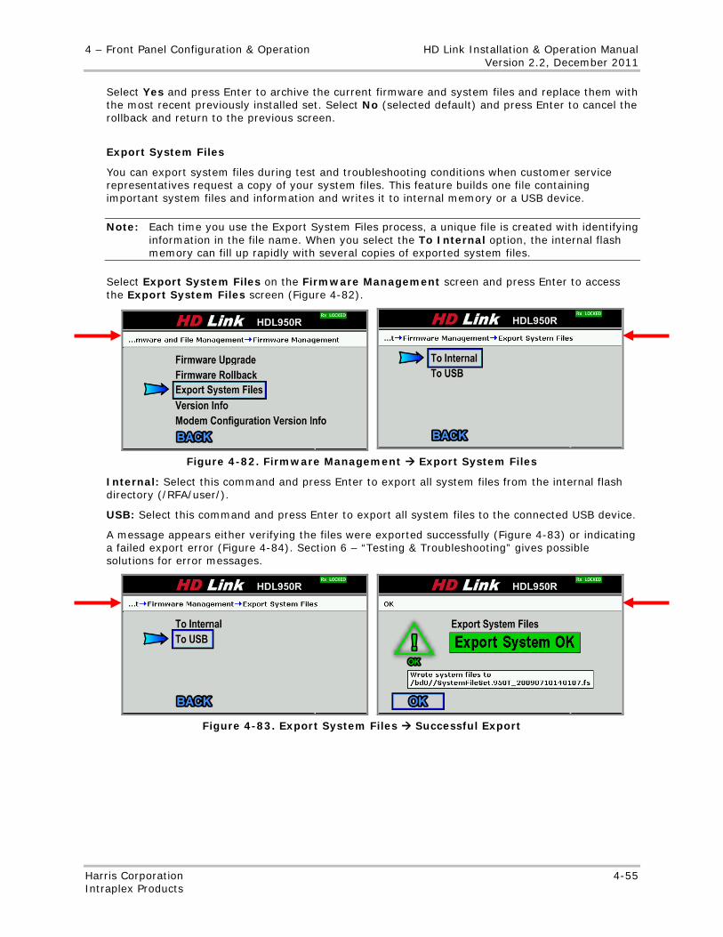
4 – Front Panel Configuration & Operation HD Link Installation & Operation Manual Version 2.2, December 2011
Harris Corporation 4-55 Intraplex Products
Select Yes and press Enter to archive the current firmware and system files and replace them with the most recent previously installed set. Select No (selected default) and press Enter to cancel the rollback and return to the previous screen.
Export System Files
You can export system files during test and troubleshooting conditions when customer service representatives request a copy of your system files. This feature builds one file containing important system files and information and writes it to internal memory or a USB device.
Note: Each time you use the Export System Files process, a unique file is created with identifying information in the file name. When you select the To Internal option, the internal flash memory can fill up rapidly with several copies of exported system files.
Select Export System Files on the Firmware Management screen and press Enter to access the Export System Files screen (Figure 4-82).
Figure 4-82. Firmware Management Export System Files
Internal: Select this command and press Enter to export all system files from the internal flash directory (/RFA/user/).
USB: Select this command and press Enter to export all system files to the connected USB device.
A message appears either verifying the files were exported successfully (Figure 4-83) or indicating a failed export error (Figure 4-84). Section 6 – “Testing & Troubleshooting” gives possible solutions for error messages.
Figure 4-83. Export System Files Successful Export
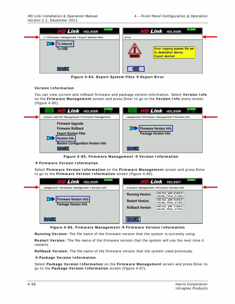
HD Link Installation & Operation Manual 4 – Front Panel Configuration & Operation Version 2.2, December 2011
4-56 Harris Corporation Intraplex Products
Figure 4-84. Export System Files Export Error
Version Information
You can view current and rollback firmware and package version information. Select Version Info on the Firmware Management screen and press Enter to go to the Version Info menu screen (Figure 4-85).
Figure 4-85. Firmware Management Version Information
Firmware Version Information
Select Firmware Version Information on the Firmware Management screen and press Enter to go to the Firmware Version Information screen (Figure 4-86).
Figure 4-86. Firmware Management Firmware Version Information
Running Version: The file name of the firmware version that the system is currently using.
Restart Version: The file name of the firmware version that the system will use the next time it restarts.
Rollback Version: The file name of the firmware version that the system used previously.
Package Version Information
Select Package Version Information on the Firmware Management screen and press Enter to go to the Package Version Information screen (Figure 4-87).
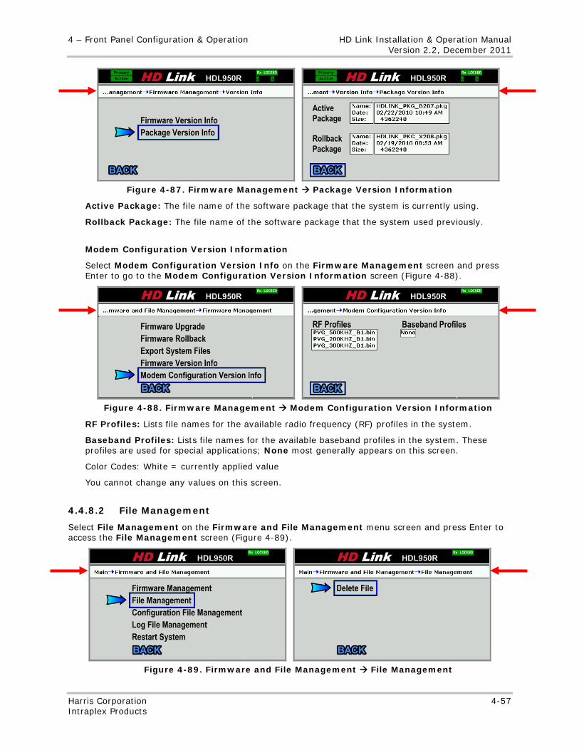
4 – Front Panel Configuration & Operation HD Link Installation & Operation Manual Version 2.2, December 2011
Harris Corporation 4-57 Intraplex Products
Figure 4-87. Firmware Management Package Version Information
Active Package: The file name of the software package that the system is currently using.
Rollback Package: The file name of the software package that the system used previously.
Modem Configuration Version Information
Select Modem Configuration Version Info on the Firmware Management screen and press Enter to go to the Modem Configuration Version Information screen (Figure 4-88).
Figure 4-88. Firmware Management Modem Configuration Version Information
RF Profiles: Lists file names for the available radio frequency (RF) profiles in the system.
Baseband Profiles: Lists file names for the available baseband profiles in the system. These profiles are used for special applications; None most generally appears on this screen.
Color Codes: White = currently applied value
You cannot change any values on this screen.
4.4.8.2 File Management
Select File Management on the Firmware and File Management menu screen and press Enter to access the File Management screen (Figure 4-89).
Figure 4-89. Firmware and File Management File Management
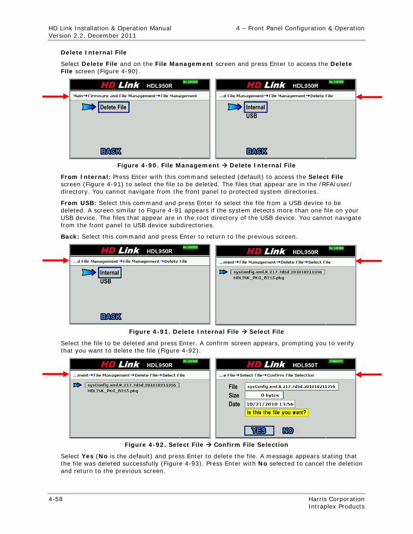
HD Link Installation & Operation Manual 4 – Front Panel Configuration & Operation Version 2.2, December 2011
4-58 Harris Corporation Intraplex Products
Delete Internal File
Select Delete File and on the File Management screen and press Enter to access the Delete File screen (Figure 4-90).
Figure 4-90. File Management Delete Internal File
From Internal: Press Enter with this command selected (default) to access the Select File screen (Figure 4-91) to select the file to be deleted. The files that appear are in the /RFA/user/ directory. You cannot navigate from the front panel to protected system directories.
From USB: Select this command and press Enter to select the file from a USB device to be deleted. A screen similar to Figure 4-91 appears if the system detects more than one file on your USB device. The files that appear are in the root directory of the USB device. You cannot navigate from the front panel to USB device subdirectories.
Back: Select this command and press Enter to return to the previous screen.
Figure 4-91. Delete Internal File Select File
Select the file to be deleted and press Enter. A confirm screen appears, prompting you to verify that you want to delete the file (Figure 4-92).
Figure 4-92. Select File Confirm File Selection
Select Yes (No is the default) and press Enter to delete the file. A message appears stating that the file was deleted successfully (Figure 4-93). Press Enter with No selected to cancel the deletion and return to the previous screen.
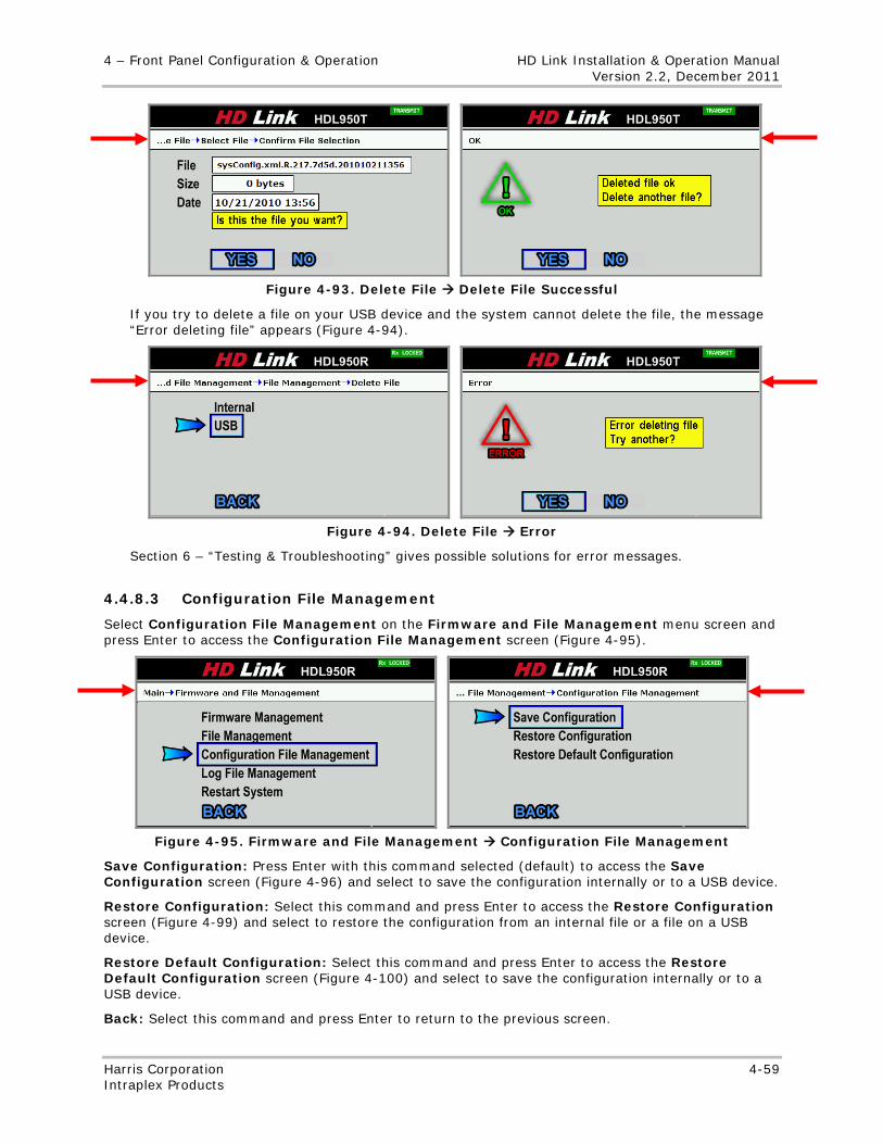
4 – Front Panel Configuration & Operation HD Link Installation & Operation Manual Version 2.2, December 2011
Harris Corporation 4-59 Intraplex Products
Figure 4-93. Delete File Delete File Successful
If you try to delete a file on your USB device and the system cannot delete the file, the message “Error deleting file” appears (Figure 4-94).
Figure 4-94. Delete File Error
Section 6 – “Testing & Troubleshooting” gives possible solutions for error messages.
4.4.8.3 Configuration File Management
Select Configuration File Management on the Firmware and File Management menu screen and press Enter to access the Configuration File Management screen (Figure 4-95).
Figure 4-95. Firmware and File Management Configuration File Management
Save Configuration: Press Enter with this command selected (default) to access the Save Configuration screen (Figure 4-96) and select to save the configuration internally or to a USB device.
Restore Configuration: Select this command and press Enter to access the Restore Configuration screen (Figure 4-99) and select to restore the configuration from an internal file or a file on a USB device.
Restore Default Configuration: Select this command and press Enter to access the Restore Default Configuration screen (Figure 4-100) and select to save the configuration internally or to a USB device.
Back: Select this command and press Enter to return to the previous screen.
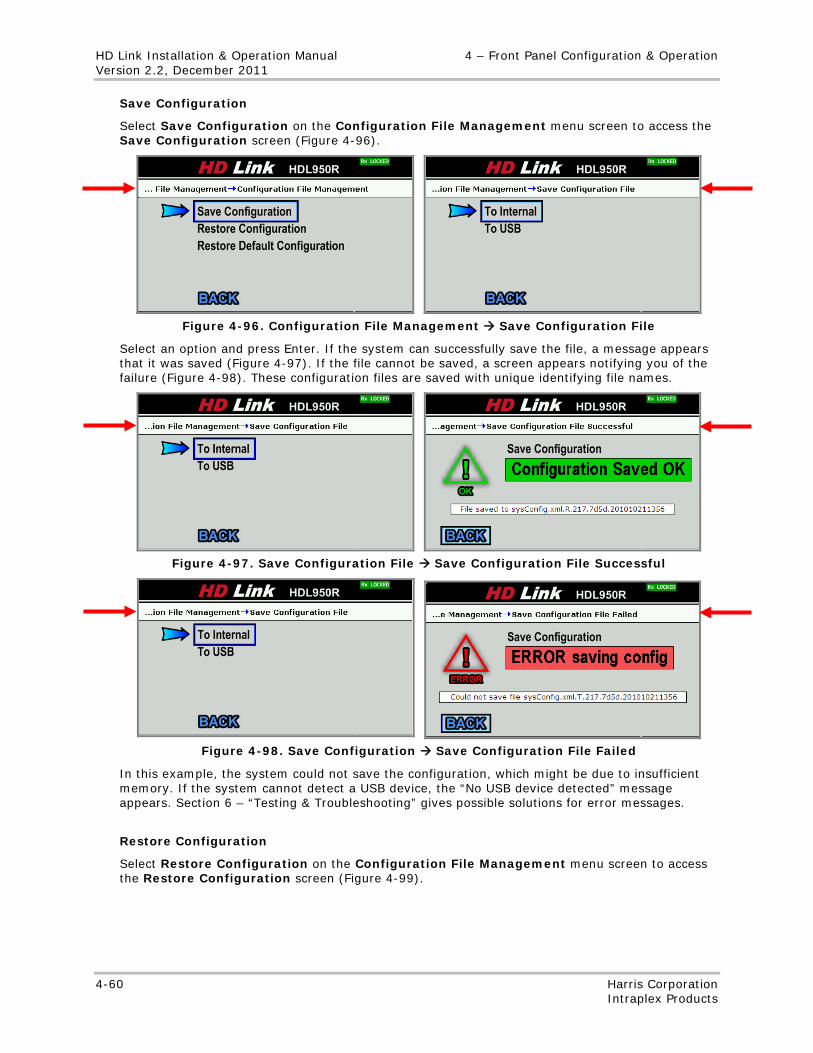
HD Link Installation & Operation Manual 4 – Front Panel Configuration & Operation Version 2.2, December 2011
4-60 Harris Corporation Intraplex Products
Save Configuration
Select Save Configuration on the Configuration File Management menu screen to access the Save Configuration screen (Figure 4-96).
Figure 4-96. Configuration File Management Save Configuration File
Select an option and press Enter. If the system can successfully save the file, a message appears that it was saved (Figure 4-97). If the file cannot be saved, a screen appears notifying you of the failure (Figure 4-98). These configuration files are saved with unique identifying file names.
Figure 4-97. Save Configuration File Save Configuration File Successful
Figure 4-98. Save Configuration Save Configuration File Failed
In this example, the system could not save the configuration, which might be due to insufficient memory. If the system cannot detect a USB device, the “No USB device detected” message appears. Section 6 – “Testing & Troubleshooting” gives possible solutions for error messages.
Restore Configuration
Select Restore Configuration on the Configuration File Management menu screen to access the Restore Configuration screen (Figure 4-99).
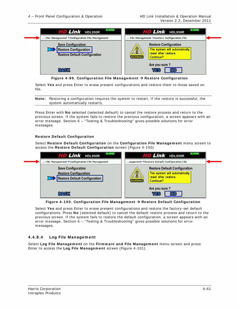
4 – Front Panel Configuration & Operation HD Link Installation & Operation Manual Version 2.2, December 2011
Harris Corporation 4-61 Intraplex Products
Figure 4-99. Configuration File Management Restore Configuration
Select Yes and press Enter to erase present configurations and restore them to those saved on file.
Note: Restoring a configuration requires the system to restart. If the restore is successful, the system automatically restarts.
Press Enter with No selected (selected default) to cancel the restore process and return to the previous screen. If the system fails to restore the previous configuration, a screen appears with an error message. Section 6 – “Testing & Troubleshooting” gives possible solutions for error messages.
Restore Default Configuration
Select Restore Default Configuration on the Configuration File Management menu screen to access the Restore Default Configuration screen (Figure 4-100).
Figure 4-100. Configuration File Management Restore Default Configuration
Select Yes and press Enter to erase present configurations and restore the factory-set default configurations. Press No (selected default) to cancel the default restore process and return to the previous screen. If the system fails to restore the default configuration, a screen appears with an error message. Section 6 – “Testing & Troubleshooting” gives possible solutions for error messages.
4.4.8.4 Log File Management
Select Log File Management on the Firmware and File Management menu screen and press Enter to access the Log File Management screen (Figure 4-101).
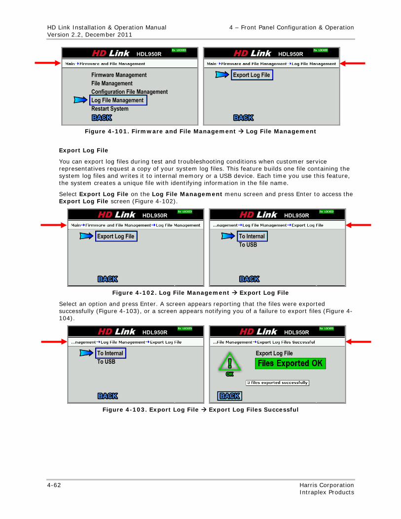
HD Link Installation & Operation Manual 4 – Front Panel Configuration & Operation Version 2.2, December 2011
4-62 Harris Corporation Intraplex Products
Figure 4-101. Firmware and File Management Log File Management
Export Log File
You can export log files during test and troubleshooting conditions when customer service representatives request a copy of your system log files. This feature builds one file containing the system log files and writes it to internal memory or a USB device. Each time you use this feature, the system creates a unique file with identifying information in the file name.
Select Export Log File on the Log File Management menu screen and press Enter to access the Export Log File screen (Figure 4-102).
Figure 4-102. Log File Management Export Log File
Select an option and press Enter. A screen appears reporting that the files were exported successfully (Figure 4-103), or a screen appears notifying you of a failure to export files (Figure 4-104).
Figure 4-103. Export Log File Export Log Files Successful
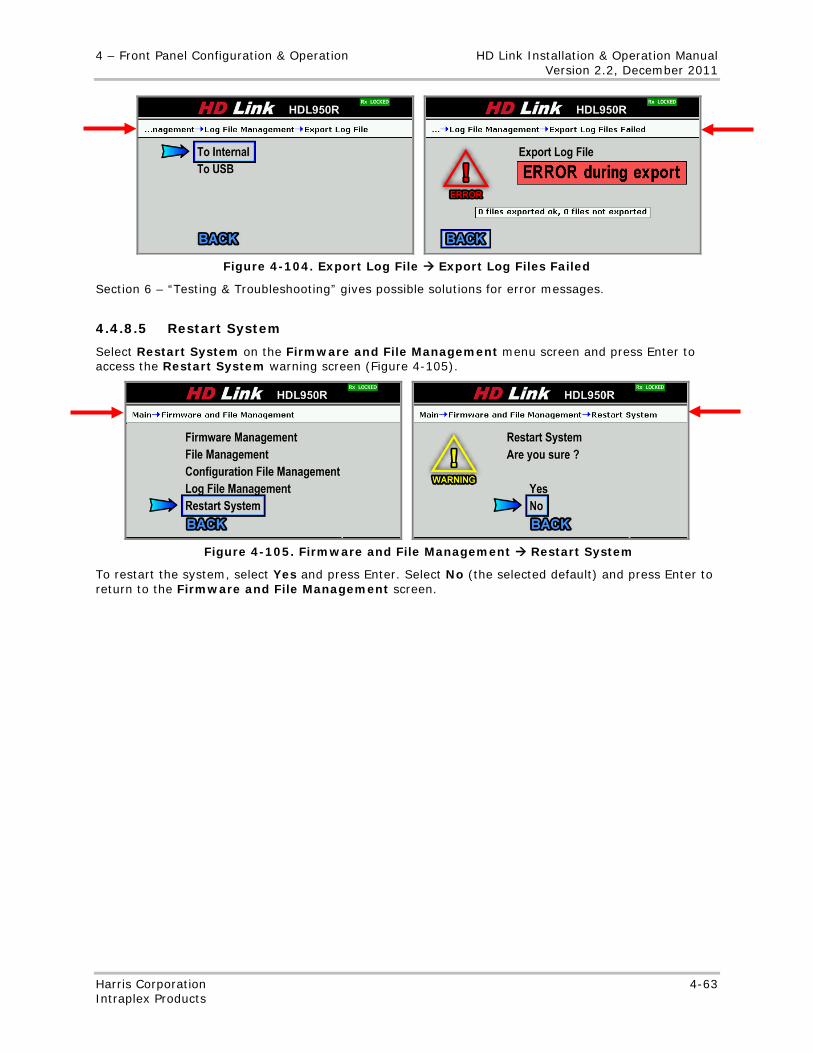
4 – Front Panel Configuration & Operation HD Link Installation & Operation Manual Version 2.2, December 2011
Harris Corporation 4-63 Intraplex Products
Figure 4-104. Export Log File Export Log Files Failed
Section 6 – “Testing & Troubleshooting” gives possible solutions for error messages.
4.4.8.5 Restart System
Select Restart System on the Firmware and File Management menu screen and press Enter to access the Restart System warning screen (Figure 4-105).
Figure 4-105. Firmware and File Management Restart System
To restart the system, select Yes and press Enter. Select No (the selected default) and press Enter to return to the Firmware and File Management screen.

No header
4-64 Harris Corporation Intraplex Products
This page is left blank intentionally.
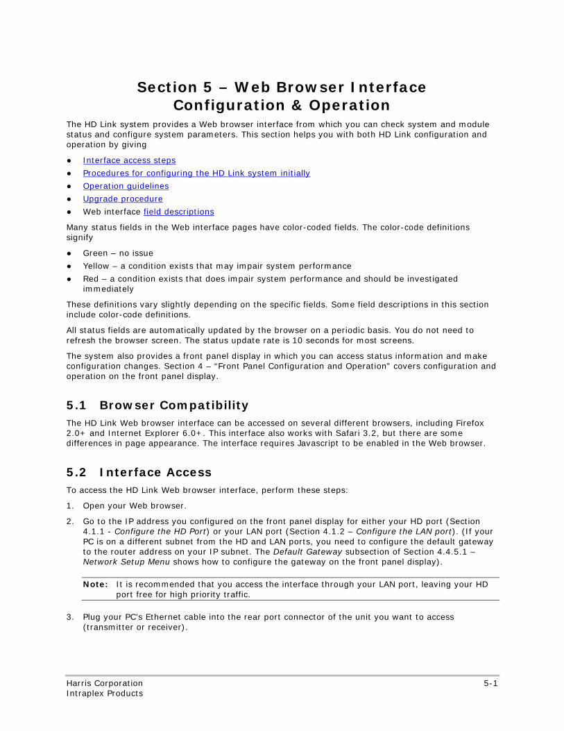
No header here
Harris Corporation 5-1 Intraplex Products
Section 5 – Web Browser Interface Configuration & Operation
The HD Link system provides a Web browser interface from which you can check system and module status and configure system parameters. This section helps you with both HD Link configuration and operation by giving
● Interface access steps
● Procedures for configuring the HD Link system initially
● Operation guidelines
● Upgrade procedure
● Web interface field descriptions
Many status fields in the Web interface pages have color-coded fields. The color-code definitions signify
● Green – no issue
● Yellow – a condition exists that may impair system performance
● Red – a condition exists that does impair system performance and should be investigated immediately
These definitions vary slightly depending on the specific fields. Some field descriptions in this section include color-code definitions.
All status fields are automatically updated by the browser on a periodic basis. You do not need to refresh the browser screen. The status update rate is 10 seconds for most screens.
The system also provides a front panel display in which you can access status information and make configuration changes. Section 4 – “Front Panel Configuration and Operation” covers configuration and operation on the front panel display.
5.1 Browser Compatibility The HD Link Web browser interface can be accessed on several different browsers, including Firefox 2.0+ and Internet Explorer 6.0+. This interface also works with Safari 3.2, but there are some differences in page appearance. The interface requires Javascript to be enabled in the Web browser.
5.2 Interface Access To access the HD Link Web browser interface, perform these steps:
1. Open your Web browser.
2. Go to the IP address you configured on the front panel display for either your HD port (Section 4.1.1 - Configure the HD Port) or your LAN port (Section 4.1.2 – Configure the LAN port). (If your PC is on a different subnet from the HD and LAN ports, you need to configure the default gateway to the router address on your IP subnet. The Default Gateway subsection of Section 4.4.5.1 – Network Setup Menu shows how to configure the gateway on the front panel display).
Note: It is recommended that you access the interface through your LAN port, leaving your HD port free for high priority traffic.
3. Plug your PC’s Ethernet cable into the rear port connector of the unit you want to access (transmitter or receiver).
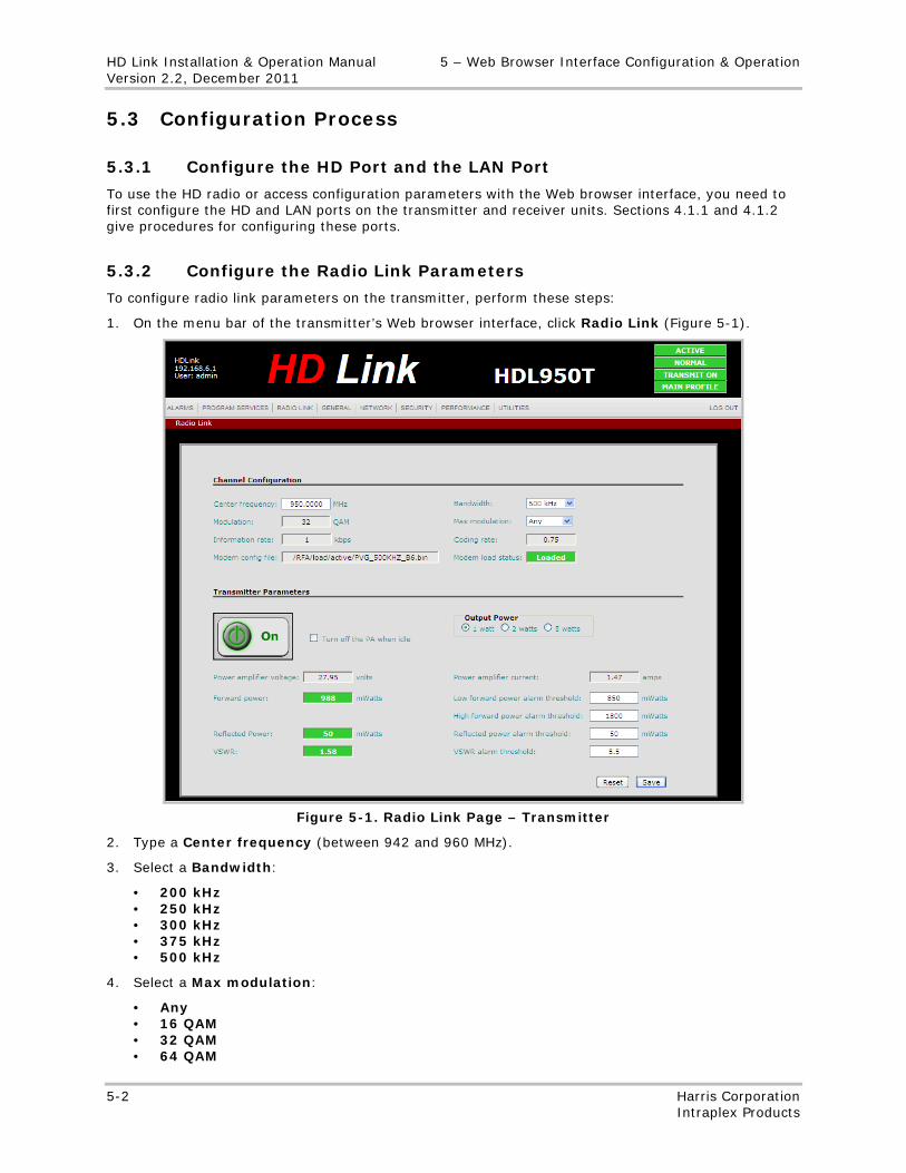
HD Link Installation & Operation Manual 5 – Web Browser Interface Configuration & Operation Version 2.2, December 2011
5-2 Harris Corporation Intraplex Products
5.3 Configuration Process
5.3.1 Configure the HD Port and the LAN Port
To use the HD radio or access configuration parameters with the Web browser interface, you need to first configure the HD and LAN ports on the transmitter and receiver units. Sections 4.1.1 and 4.1.2 give procedures for configuring these ports.
5.3.2 Configure the Radio Link Parameters
To configure radio link parameters on the transmitter, perform these steps:
1. On the menu bar of the transmitter’s Web browser interface, click Radio Link (Figure 5-1).
Figure 5-1. Radio Link Page – Transmitter
2. Type a Center frequency (between 942 and 960 MHz).
3. Select a Bandwidth:
• 200 kHz • 250 kHz • 300 kHz • 375 kHz • 500 kHz
4. Select a Max modulation:
• Any • 16 QAM • 32 QAM • 64 QAM
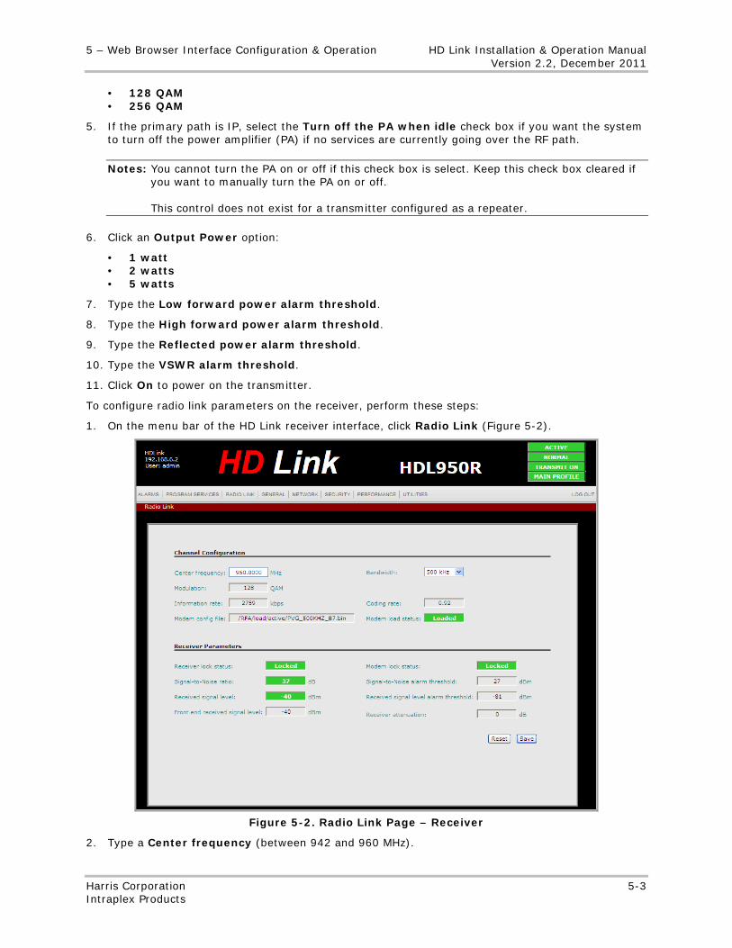
5 – Web Browser Interface Configuration & Operation HD Link Installation & Operation Manual Version 2.2, December 2011
Harris Corporation 5-3 Intraplex Products
• 128 QAM • 256 QAM
5. If the primary path is IP, select the Turn off the PA when idle check box if you want the system to turn off the power amplifier (PA) if no services are currently going over the RF path.
Notes: You cannot turn the PA on or off if this check box is select. Keep this check box cleared if you want to manually turn the PA on or off. This control does not exist for a transmitter configured as a repeater.
6. Click an Output Power option:
• 1 watt • 2 watts • 5 watts
7. Type the Low forward power alarm threshold.
8. Type the High forward power alarm threshold.
9. Type the Reflected power alarm threshold.
10. Type the VSWR alarm threshold.
11. Click On to power on the transmitter.
To configure radio link parameters on the receiver, perform these steps:
1. On the menu bar of the HD Link receiver interface, click Radio Link (Figure 5-2).
Figure 5-2. Radio Link Page – Receiver
2. Type a Center frequency (between 942 and 960 MHz).
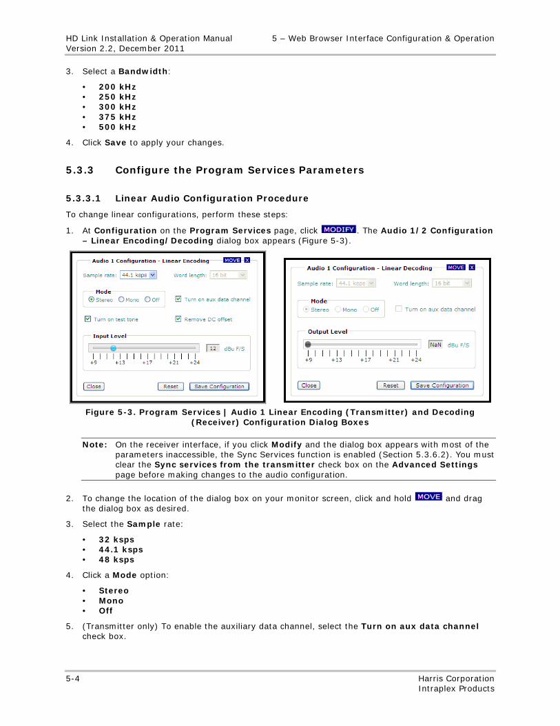
HD Link Installation & Operation Manual 5 – Web Browser Interface Configuration & Operation Version 2.2, December 2011
5-4 Harris Corporation Intraplex Products
3. Select a Bandwidth:
• 200 kHz • 250 kHz • 300 kHz • 375 kHz • 500 kHz
4. Click Save to apply your changes.
5.3.3 Configure the Program Services Parameters
5.3.3.1 Linear Audio Configuration Procedure
To change linear configurations, perform these steps:
1. At Configuration on the Program Services page, click . The Audio 1/2 Configuration – Linear Encoding/Decoding dialog box appears (Figure 5-3).
Figure 5-3. Program Services | Audio 1 Linear Encoding (Transmitter) and Decoding
(Receiver) Configuration Dialog Boxes
Note: On the receiver interface, if you click Modify and the dialog box appears with most of the parameters inaccessible, the Sync Services function is enabled (Section 5.3.6.2). You must clear the Sync services from the transmitter check box on the Advanced Settings page before making changes to the audio configuration.
2. To change the location of the dialog box on your monitor screen, click and hold and drag the dialog box as desired.
3. Select the Sample rate:
• 32 ksps • 44.1 ksps • 48 ksps
4. Click a Mode option:
• Stereo • Mono • Off
5. (Transmitter only) To enable the auxiliary data channel, select the Turn on aux data channel check box.
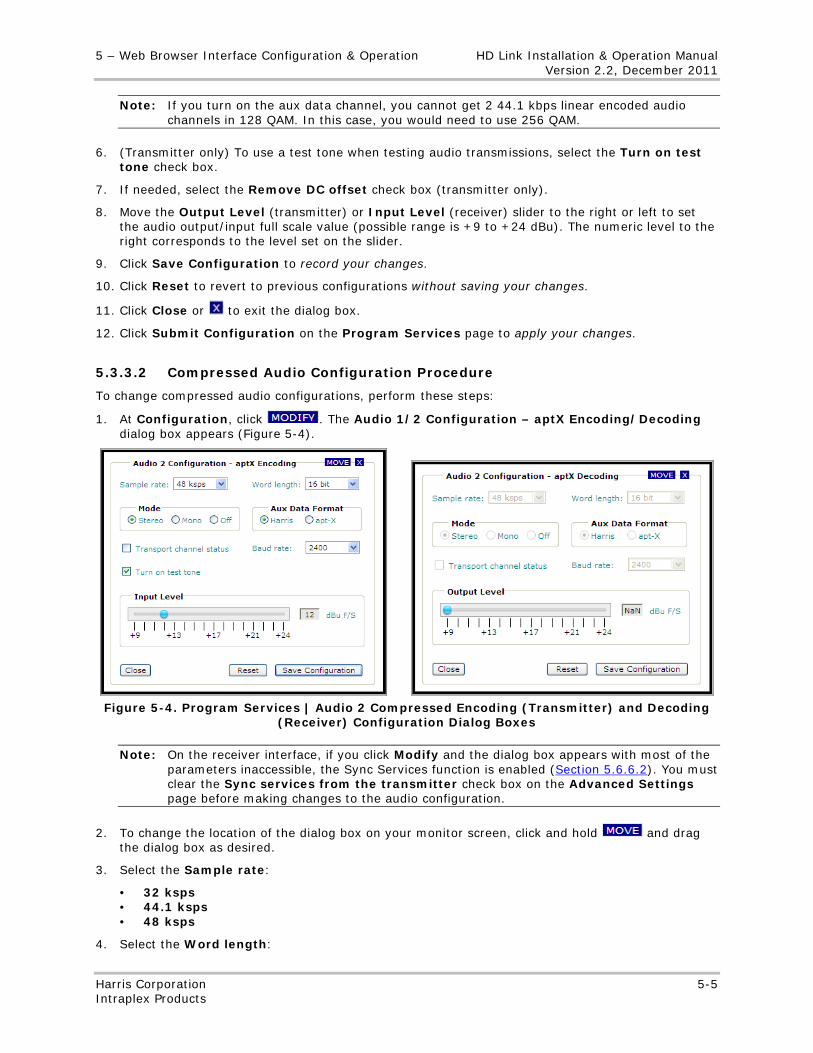
5 – Web Browser Interface Configuration & Operation HD Link Installation & Operation Manual Version 2.2, December 2011
Harris Corporation 5-5 Intraplex Products
Note: If you turn on the aux data channel, you cannot get 2 44.1 kbps linear encoded audio channels in 128 QAM. In this case, you would need to use 256 QAM.
6. (Transmitter only) To use a test tone when testing audio transmissions, select the Turn on test tone check box.
7. If needed, select the Remove DC offset check box (transmitter only).
8. Move the Output Level (transmitter) or Input Level (receiver) slider to the right or left to set the audio output/input full scale value (possible range is +9 to +24 dBu). The numeric level to the right corresponds to the level set on the slider.
9. Click Save Configuration to record your changes.
10. Click Reset to revert to previous configurations without saving your changes.
11. Click Close or to exit the dialog box.
12. Click Submit Configuration on the Program Services page to apply your changes.
5.3.3.2 Compressed Audio Configuration Procedure
To change compressed audio configurations, perform these steps:
1. At Configuration, click . The Audio 1/2 Configuration – aptX Encoding/Decoding dialog box appears (Figure 5-4).
Figure 5-4. Program Services | Audio 2 Compressed Encoding (Transmitter) and Decoding
(Receiver) Configuration Dialog Boxes
Note: On the receiver interface, if you click Modify and the dialog box appears with most of the parameters inaccessible, the Sync Services function is enabled (Section 5.6.6.2). You must clear the Sync services from the transmitter check box on the Advanced Settings page before making changes to the audio configuration.
2. To change the location of the dialog box on your monitor screen, click and hold and drag the dialog box as desired.
3. Select the Sample rate:
• 32 ksps • 44.1 ksps • 48 ksps
4. Select the Word length:
HD Link Installation & Operation Manual 5 – Web Browser Interface Configuration & Operation Version 2.2, December 2011
5-6 Harris Corporation Intraplex Products
• 16 bit • 20 bit • 24 bit
5. Click a Mode option:
• Stereo • Mono • Off
6. Select an Aux Data Format:
• Harris • apt-X
7. Select the Transport channel status check box.
8. Select the Baud rate:
• None • 1200 • 2400 • 4800 • 9600
Note: A system configured with linear audio has a fixed baud rate of 9600. The available baud rate for a system configured with compressed audio depends on the bandwidth.
9. To use a test tone when testing audio transmissions, select the Turn on test tone check box (transmitter only).
10. Move the Input Level (transmitter) or Output Level (receiver) slider to the right or left to set the audio output/input full scale value (possible range is +9 to +24 dBu). The numeric level to the right corresponds to the level set on the slider.
11. Click Save Configuration to record your changes.
12. Click Reset to revert to previous configurations without saving your changes.
13. Click Close or to exit the dialog box.
14. Click Submit Configuration on the Program Services page to apply your changes.
5.3.3.3 Auxiliary Port Configuration Procedure
1. At Configuration, click . The Audio 1/2 Configuration – G.722 Encoding/Decoding dialog box appears (Figure 5-5).
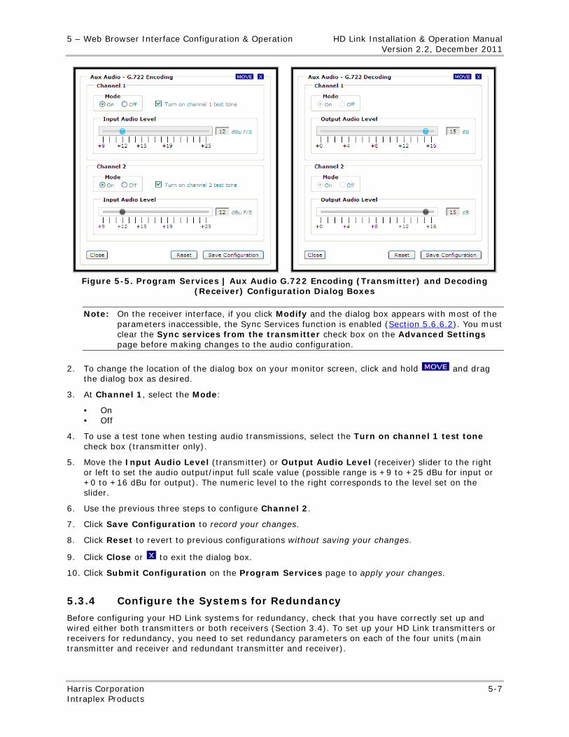
5 – Web Browser Interface Configuration & Operation HD Link Installation & Operation Manual Version 2.2, December 2011
Harris Corporation 5-7 Intraplex Products
Figure 5-5. Program Services | Aux Audio G.722 Encoding (Transmitter) and Decoding
(Receiver) Configuration Dialog Boxes
Note: On the receiver interface, if you click Modify and the dialog box appears with most of the parameters inaccessible, the Sync Services function is enabled (Section 5.6.6.2). You must clear the Sync services from the transmitter check box on the Advanced Settings page before making changes to the audio configuration.
2. To change the location of the dialog box on your monitor screen, click and hold and drag the dialog box as desired.
3. At Channel 1, select the Mode:
• On • Off
4. To use a test tone when testing audio transmissions, select the Turn on channel 1 test tone check box (transmitter only).
5. Move the Input Audio Level (transmitter) or Output Audio Level (receiver) slider to the right or left to set the audio output/input full scale value (possible range is +9 to +25 dBu for input or +0 to +16 dBu for output). The numeric level to the right corresponds to the level set on the slider.
6. Use the previous three steps to configure Channel 2.
7. Click Save Configuration to record your changes.
8. Click Reset to revert to previous configurations without saving your changes.
9. Click Close or to exit the dialog box.
10. Click Submit Configuration on the Program Services page to apply your changes.
5.3.4 Configure the Systems for Redundancy
Before configuring your HD Link systems for redundancy, check that you have correctly set up and wired either both transmitters or both receivers (Section 3.4). To set up your HD Link transmitters or receivers for redundancy, you need to set redundancy parameters on each of the four units (main transmitter and receiver and redundant transmitter and receiver).
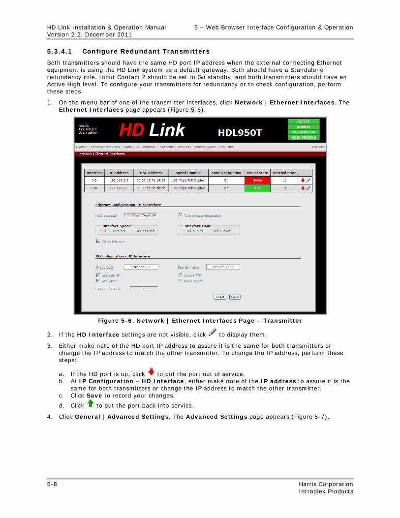
HD Link Installation & Operation Manual 5 – Web Browser Interface Configuration & Operation Version 2.2, December 2011
5-8 Harris Corporation Intraplex Products
5.3.4.1 Configure Redundant Transmitters
Both transmitters should have the same HD port IP address when the external connecting Ethernet equipment is using the HD Link system as a default gateway. Both should have a Standalone redundancy role. Input Contact 2 should be set to Go standby, and both transmitters should have an Active High level. To configure your transmitters for redundancy or to check configuration, perform these steps:
1. On the menu bar of one of the transmitter interfaces, click Network | Ethernet Interfaces. The Ethernet Interfaces page appears (Figure 5-6).
Figure 5-6. Network | Ethernet Interfaces Page – Transmitter
2. If the HD Interface settings are not visible, click to display them.
3. Either make note of the HD port IP address to assure it is the same for both transmitters or change the IP address to match the other transmitter. To change the IP address, perform these steps:
a. If the HD port is up, click to put the port out of service. b. At IP Configuration – HD Interface, either make note of the IP address to assure it is the
same for both transmitters or change the IP address to match the other transmitter. c. Click Save to record your changes.
d. Click to put the port back into service.
4. Click General | Advanced Settings. The Advanced Settings page appears (Figure 5-7).
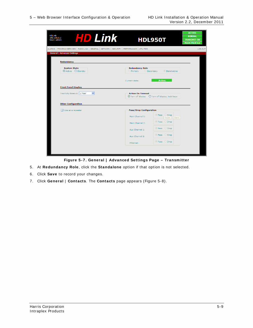
5 – Web Browser Interface Configuration & Operation HD Link Installation & Operation Manual Version 2.2, December 2011
Harris Corporation 5-9 Intraplex Products
Figure 5-7. General | Advanced Settings Page – Transmitter
5. At Redundancy Role, click the Standalone option if that option is not selected.
6. Click Save to record your changes.
7. Click General | Contacts. The Contacts page appears (Figure 5-8).
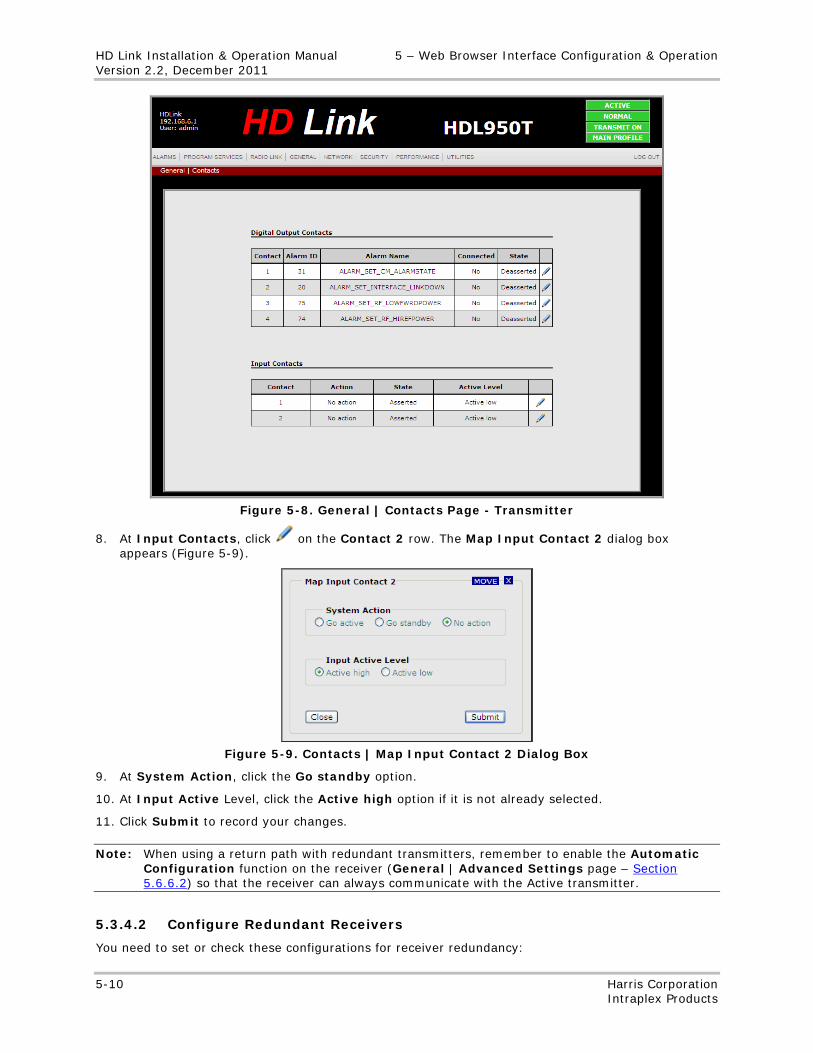
HD Link Installation & Operation Manual 5 – Web Browser Interface Configuration & Operation Version 2.2, December 2011
5-10 Harris Corporation Intraplex Products
Figure 5-8. General | Contacts Page - Transmitter
8. At Input Contacts, click on the Contact 2 row. The Map Input Contact 2 dialog box appears (Figure 5-9).
Figure 5-9. Contacts | Map Input Contact 2 Dialog Box
9. At System Action, click the Go standby option.
10. At Input Active Level, click the Active high option if it is not already selected.
11. Click Submit to record your changes.
Note: When using a return path with redundant transmitters, remember to enable the Automatic Configuration function on the receiver (General | Advanced Settings page – Section 5.6.6.2) so that the receiver can always communicate with the Active transmitter.
5.3.4.2 Configure Redundant Receivers
You need to set or check these configurations for receiver redundancy:
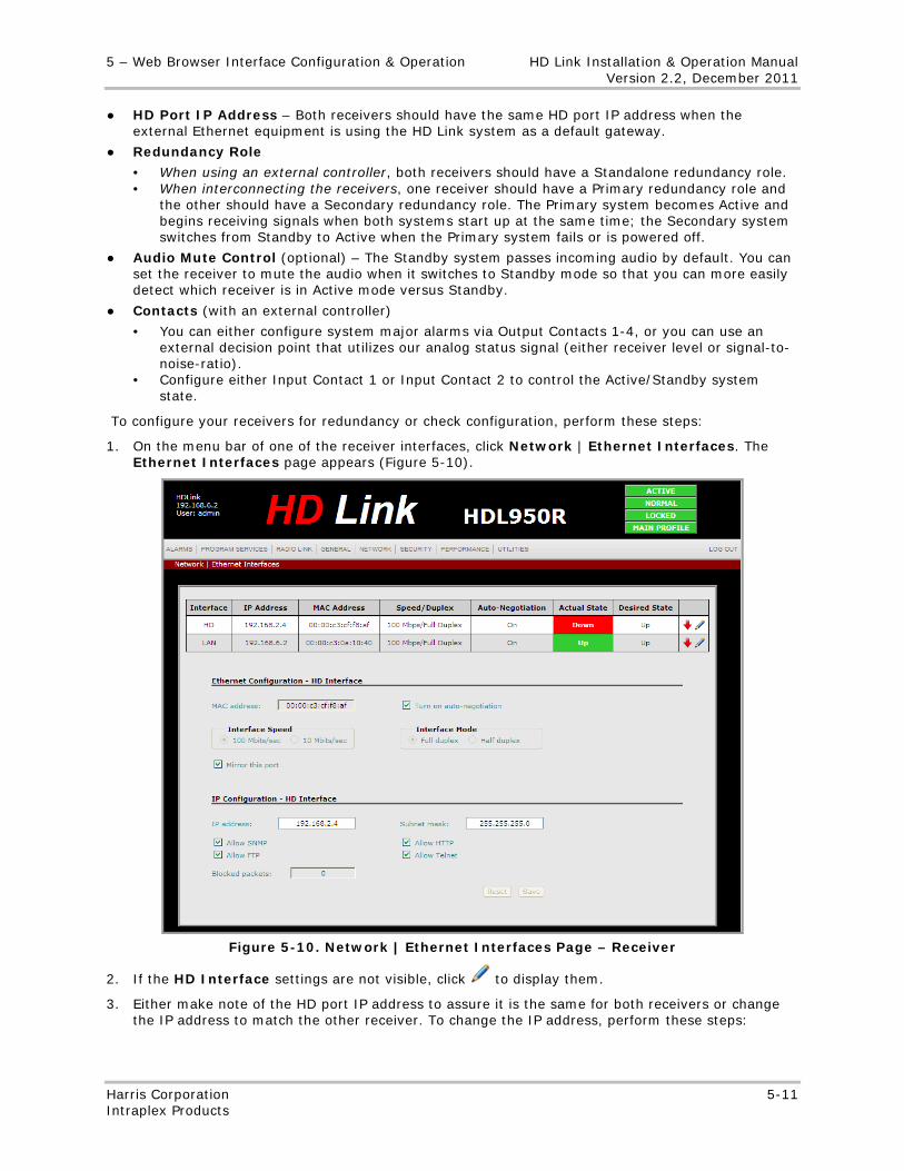
5 – Web Browser Interface Configuration & Operation HD Link Installation & Operation Manual Version 2.2, December 2011
Harris Corporation 5-11 Intraplex Products
● HD Port IP Address – Both receivers should have the same HD port IP address when the external Ethernet equipment is using the HD Link system as a default gateway.
● Redundancy Role
• When using an external controller, both receivers should have a Standalone redundancy role. • When interconnecting the receivers, one receiver should have a Primary redundancy role and
the other should have a Secondary redundancy role. The Primary system becomes Active and begins receiving signals when both systems start up at the same time; the Secondary system switches from Standby to Active when the Primary system fails or is powered off.
● Audio Mute Control (optional) – The Standby system passes incoming audio by default. You can set the receiver to mute the audio when it switches to Standby mode so that you can more easily detect which receiver is in Active mode versus Standby.
● Contacts (with an external controller)
• You can either configure system major alarms via Output Contacts 1-4, or you can use an external decision point that utilizes our analog status signal (either receiver level or signal-to-noise-ratio).
• Configure either Input Contact 1 or Input Contact 2 to control the Active/Standby system state.
To configure your receivers for redundancy or check configuration, perform these steps:
1. On the menu bar of one of the receiver interfaces, click Network | Ethernet Interfaces. The Ethernet Interfaces page appears (Figure 5-10).
Figure 5-10. Network | Ethernet Interfaces Page – Receiver
2. If the HD Interface settings are not visible, click to display them.
3. Either make note of the HD port IP address to assure it is the same for both receivers or change the IP address to match the other receiver. To change the IP address, perform these steps:
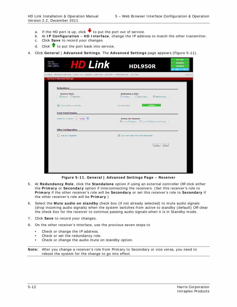
HD Link Installation & Operation Manual 5 – Web Browser Interface Configuration & Operation Version 2.2, December 2011
5-12 Harris Corporation Intraplex Products
a. If the HD port is up, click to put the port out of service. b. At IP Configuration – HD Interface, change the IP address to match the other transmitter. c. Click Save to record your changes.
d. Click to put the port back into service.
4. Click General | Advanced Settings. The Advanced Settings page appears (Figure 5-11).
Figure 5-11. General | Advanced Settings Page – Receiver
5. At Redundancy Role, click the Standalone option if using an external controller OR click either the Primary or Secondary option if interconnecting the receivers. (Set this receiver’s role to Primary if the other receiver’s role will be Secondary or set this receiver’s role to Secondary if the other receiver’s role will be Primary.)
6. Select the Mute audio on standby check box (if not already selected) to mute audio signals (drop incoming audio signals) when the system switches from active to standby (default) OR clear the check box for the receiver to continue passing audio signals when it is in Standby mode.
7. Click Save to record your changes.
8. On the other receiver’s interface, use the previous seven steps to
• Check or change the IP address. • Check or set the redundancy role. • Check or change the audio mute on standby option.
Note: After you change a receiver’s role from Primary to Secondary or vice versa, you need to reboot the system for the change to go into effect.
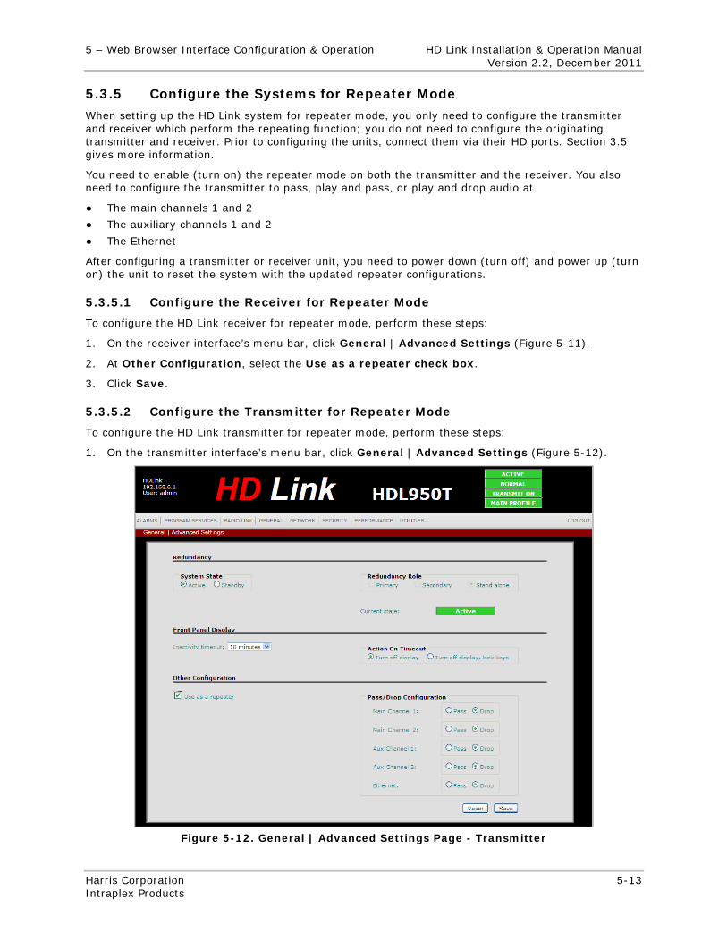
5 – Web Browser Interface Configuration & Operation HD Link Installation & Operation Manual Version 2.2, December 2011
Harris Corporation 5-13 Intraplex Products
5.3.5 Configure the Systems for Repeater Mode
When setting up the HD Link system for repeater mode, you only need to configure the transmitter and receiver which perform the repeating function; you do not need to configure the originating transmitter and receiver. Prior to configuring the units, connect them via their HD ports. Section 3.5 gives more information.
You need to enable (turn on) the repeater mode on both the transmitter and the receiver. You also need to configure the transmitter to pass, play and pass, or play and drop audio at
● The main channels 1 and 2
● The auxiliary channels 1 and 2
● The Ethernet
After configuring a transmitter or receiver unit, you need to power down (turn off) and power up (turn on) the unit to reset the system with the updated repeater configurations.
5.3.5.1 Configure the Receiver for Repeater Mode
To configure the HD Link receiver for repeater mode, perform these steps:
1. On the receiver interface’s menu bar, click General | Advanced Settings (Figure 5-11).
2. At Other Configuration, select the Use as a repeater check box.
3. Click Save.
5.3.5.2 Configure the Transmitter for Repeater Mode
To configure the HD Link transmitter for repeater mode, perform these steps:
1. On the transmitter interface’s menu bar, click General | Advanced Settings (Figure 5-12).
Figure 5-12. General | Advanced Settings Page - Transmitter
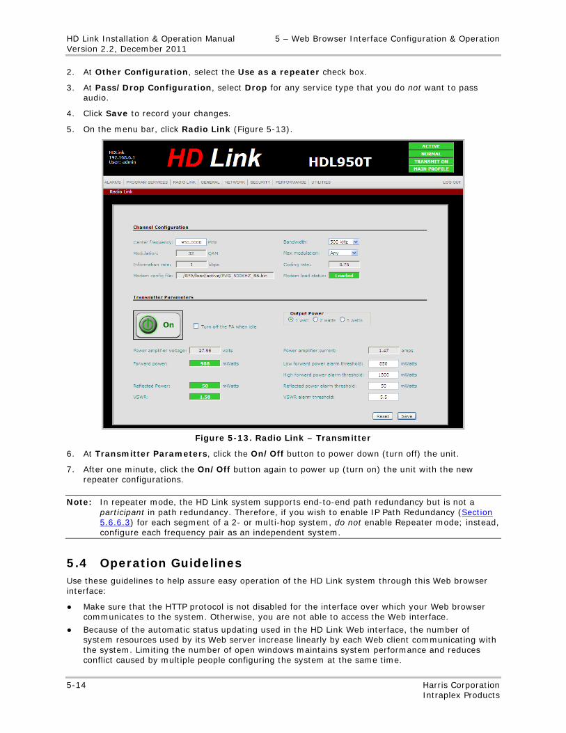
HD Link Installation & Operation Manual 5 – Web Browser Interface Configuration & Operation Version 2.2, December 2011
5-14 Harris Corporation Intraplex Products
2. At Other Configuration, select the Use as a repeater check box.
3. At Pass/Drop Configuration, select Drop for any service type that you do not want to pass audio.
4. Click Save to record your changes.
5. On the menu bar, click Radio Link (Figure 5-13).
Figure 5-13. Radio Link – Transmitter
6. At Transmitter Parameters, click the On/Off button to power down (turn off) the unit.
7. After one minute, click the On/Off button again to power up (turn on) the unit with the new repeater configurations.
Note: In repeater mode, the HD Link system supports end-to-end path redundancy but is not a participant in path redundancy. Therefore, if you wish to enable IP Path Redundancy (Section 5.6.6.3) for each segment of a 2- or multi-hop system, do not enable Repeater mode; instead, configure each frequency pair as an independent system.
5.4 Operation Guidelines Use these guidelines to help assure easy operation of the HD Link system through this Web browser interface:
● Make sure that the HTTP protocol is not disabled for the interface over which your Web browser communicates to the system. Otherwise, you are not able to access the Web interface.
● Because of the automatic status updating used in the HD Link Web interface, the number of system resources used by its Web server increase linearly by each Web client communicating with the system. Limiting the number of open windows maintains system performance and reduces conflict caused by multiple people configuring the system at the same time.
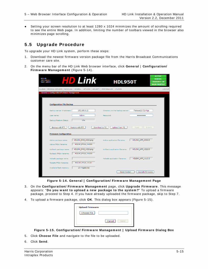
5 – Web Browser Interface Configuration & Operation HD Link Installation & Operation Manual Version 2.2, December 2011
Harris Corporation 5-15 Intraplex Products
● Setting your screen resolution to at least 1280 x 1024 minimizes the amount of scrolling required to see the entire Web page. In addition, limiting the number of toolbars viewed in the browser also minimizes page scrolling.
5.5 Upgrade Procedure To upgrade your HD Link system, perform these steps:
1. Download the newest firmware version package file from the Harris Broadcast Communications customer care site.
2. On the menu bar of the HD Link Web browser interface, click General | Configuration/ Firmware Management (Figure 5-14).
Figure 5-14. General | Configuration/Firmware Management Page
3. On the Configuration/Firmware Management page, click Upgrade Firmware. This message appears: “Do you want to upload a new package to the system?” To upload a firmware package, proceed to Step 4. If you have already uploaded the firmware package, skip to Step 7.
4. To upload a firmware package, click OK. This dialog box appears (Figure 5-15).
Figure 5-15. Configuration/Firmware Management | Upload Firmware Dialog Box
5. Click Choose File and navigate to the file to be uploaded.
6. Click Send.
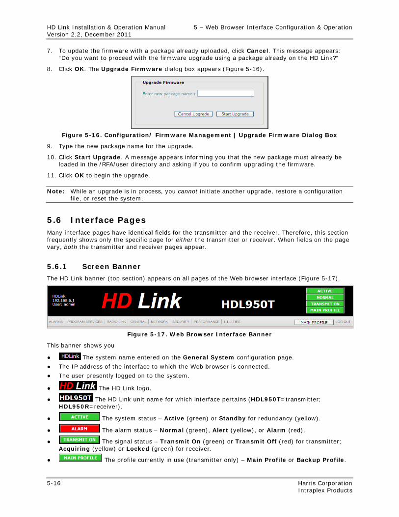
HD Link Installation & Operation Manual 5 – Web Browser Interface Configuration & Operation Version 2.2, December 2011
5-16 Harris Corporation Intraplex Products
7. To update the firmware with a package already uploaded, click Cancel. This message appears: “Do you want to proceed with the firmware upgrade using a package already on the HD Link?”
8. Click OK. The Upgrade Firmware dialog box appears (Figure 5-16).
Figure 5-16. Configuration/ Firmware Management | Upgrade Firmware Dialog Box
9. Type the new package name for the upgrade.
10. Click Start Upgrade. A message appears informing you that the new package must already be loaded in the /RFA/user directory and asking if you to confirm upgrading the firmware.
11. Click OK to begin the upgrade.
Note: While an upgrade is in process, you cannot initiate another upgrade, restore a configuration file, or reset the system.
5.6 Interface Pages Many interface pages have identical fields for the transmitter and the receiver. Therefore, this section frequently shows only the specific page for either the transmitter or receiver. When fields on the page vary, both the transmitter and receiver pages appear.
5.6.1 Screen Banner
The HD Link banner (top section) appears on all pages of the Web browser interface (Figure 5-17).
Figure 5-17. Web Browser Interface Banner
This banner shows you
● The system name entered on the General System configuration page.
● The IP address of the interface to which the Web browser is connected.
● The user presently logged on to the system.
● The HD Link logo.
● The HD Link unit name for which interface pertains (HDL950T=transmitter; HDL950R=receiver).
● The system status – Active (green) or Standby for redundancy (yellow).
● The alarm status – Normal (green), Alert (yellow), or Alarm (red).
● The signal status – Transmit On (green) or Transmit Off (red) for transmitter; Acquiring (yellow) or Locked (green) for receiver.
● The profile currently in use (transmitter only) – Main Profile or Backup Profile.
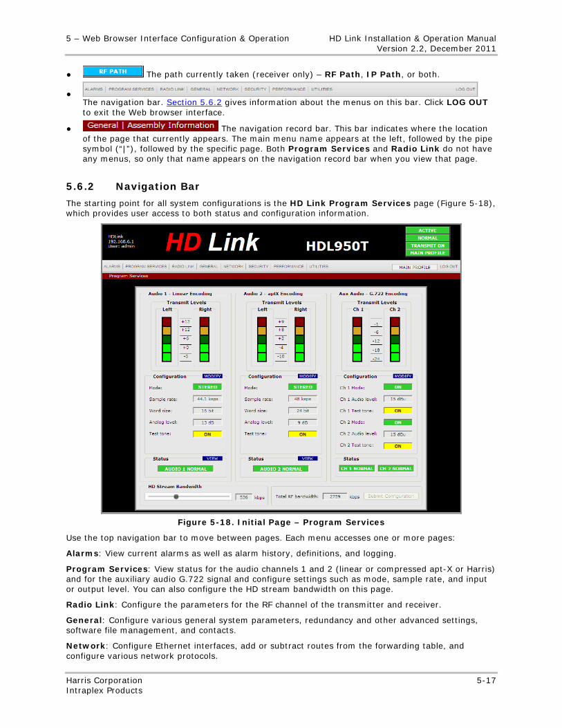
5 – Web Browser Interface Configuration & Operation HD Link Installation & Operation Manual Version 2.2, December 2011
Harris Corporation 5-17 Intraplex Products
● The path currently taken (receiver only) – RF Path, IP Path, or both.
● The navigation bar. Section 5.6.2 gives information about the menus on this bar. Click LOG OUT to exit the Web browser interface.
● The navigation record bar. This bar indicates where the location of the page that currently appears. The main menu name appears at the left, followed by the pipe symbol (“|”), followed by the specific page. Both Program Services and Radio Link do not have any menus, so only that name appears on the navigation record bar when you view that page.
5.6.2 Navigation Bar
The starting point for all system configurations is the HD Link Program Services page (Figure 5-18), which provides user access to both status and configuration information.
Figure 5-18. Initial Page – Program Services
Use the top navigation bar to move between pages. Each menu accesses one or more pages:
Alarms: View current alarms as well as alarm history, definitions, and logging.
Program Services: View status for the audio channels 1 and 2 (linear or compressed apt-X or Harris) and for the auxiliary audio G.722 signal and configure settings such as mode, sample rate, and input or output level. You can also configure the HD stream bandwidth on this page.
Radio Link: Configure the parameters for the RF channel of the transmitter and receiver.
General: Configure various general system parameters, redundancy and other advanced settings, software file management, and contacts.
Network: Configure Ethernet interfaces, add or subtract routes from the forwarding table, and configure various network protocols.
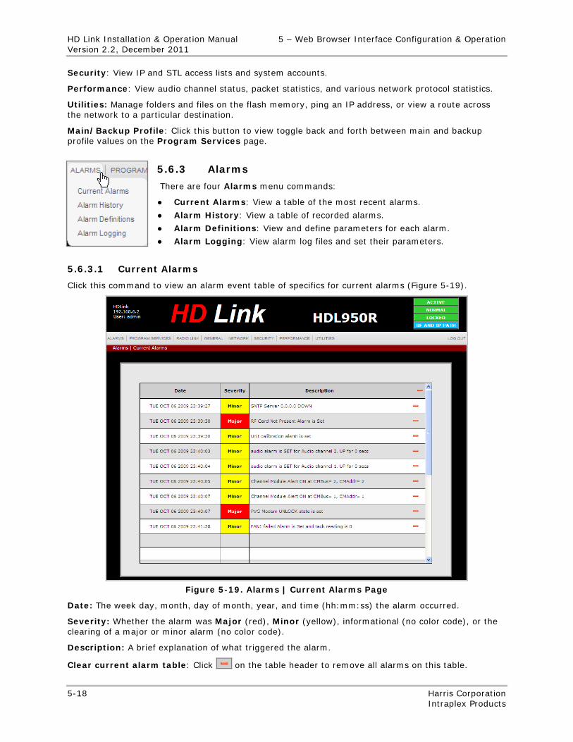
HD Link Installation & Operation Manual 5 – Web Browser Interface Configuration & Operation Version 2.2, December 2011
5-18 Harris Corporation Intraplex Products
Security: View IP and STL access lists and system accounts.
Performance: View audio channel status, packet statistics, and various network protocol statistics.
Utilities: Manage folders and files on the flash memory, ping an IP address, or view a route across the network to a particular destination.
Main/Backup Profile: Click this button to view toggle back and forth between main and backup profile values on the Program Services page.
5.6.3 Alarms
There are four Alarms menu commands:
● Current Alarms: View a table of the most recent alarms.
● Alarm History: View a table of recorded alarms.
● Alarm Definitions: View and define parameters for each alarm.
● Alarm Logging: View alarm log files and set their parameters.
5.6.3.1 Current Alarms
Click this command to view an alarm event table of specifics for current alarms (Figure 5-19).
Figure 5-19. Alarms | Current Alarms Page
Date: The week day, month, day of month, year, and time (hh:mm:ss) the alarm occurred.
Severity: Whether the alarm was Major (red), Minor (yellow), informational (no color code), or the clearing of a major or minor alarm (no color code).
Description: A brief explanation of what triggered the alarm.
Clear current alarm table: Click on the table header to remove all alarms on this table.
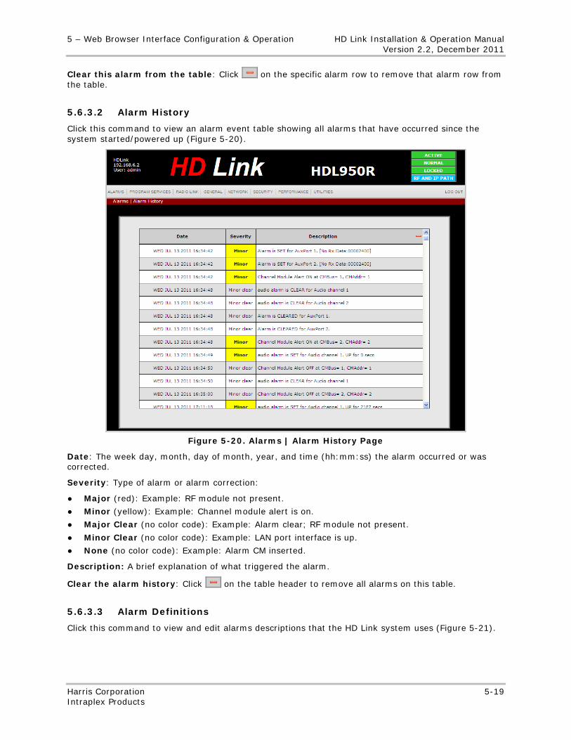
5 – Web Browser Interface Configuration & Operation HD Link Installation & Operation Manual Version 2.2, December 2011
Harris Corporation 5-19 Intraplex Products
Clear this alarm from the table: Click on the specific alarm row to remove that alarm row from the table.
5.6.3.2 Alarm History
Click this command to view an alarm event table showing all alarms that have occurred since the system started/powered up (Figure 5-20).
Figure 5-20. Alarms | Alarm History Page
Date: The week day, month, day of month, year, and time (hh:mm:ss) the alarm occurred or was corrected.
Severity: Type of alarm or alarm correction:
● Major (red): Example: RF module not present.
● Minor (yellow): Example: Channel module alert is on.
● Major Clear (no color code): Example: Alarm clear; RF module not present.
● Minor Clear (no color code): Example: LAN port interface is up.
● None (no color code): Example: Alarm CM inserted.
Description: A brief explanation of what triggered the alarm.
Clear the alarm history: Click on the table header to remove all alarms on this table.
5.6.3.3 Alarm Definitions
Click this command to view and edit alarms descriptions that the HD Link system uses (Figure 5-21).
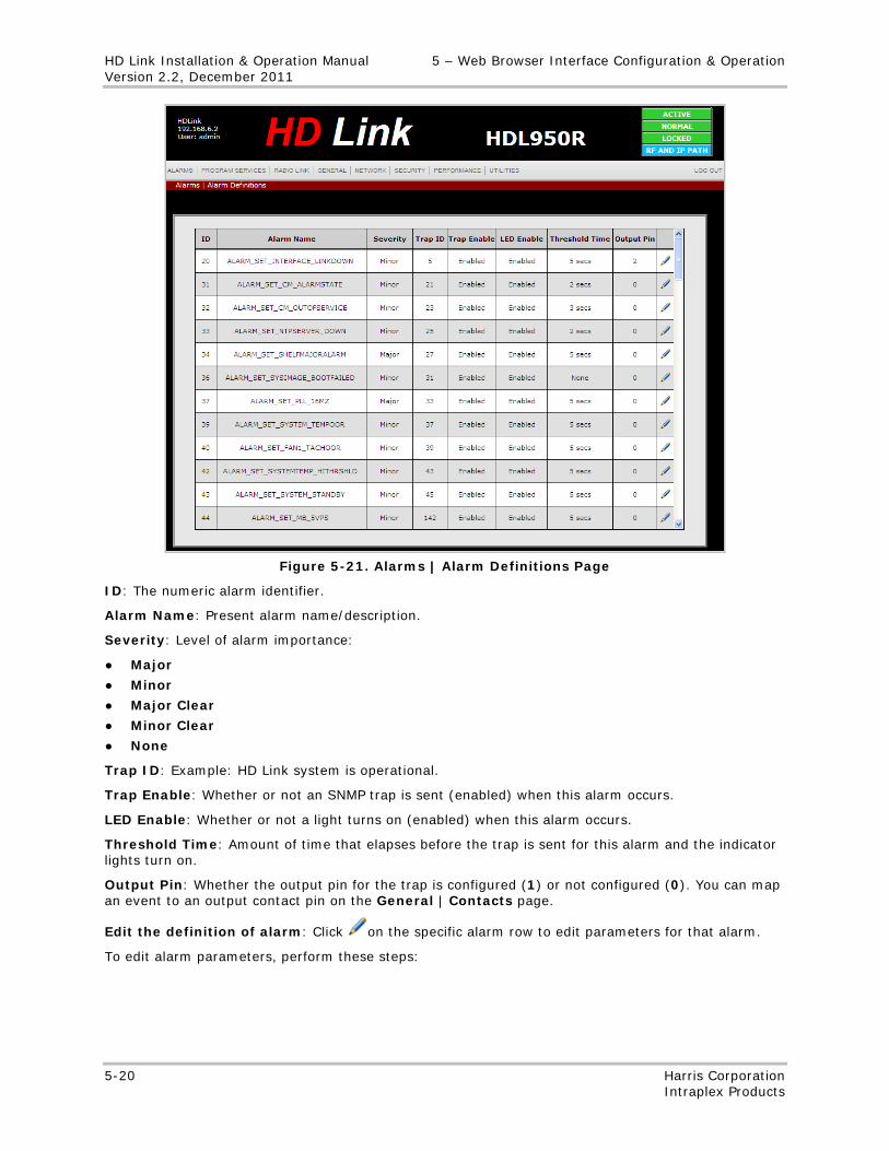
HD Link Installation & Operation Manual 5 – Web Browser Interface Configuration & Operation Version 2.2, December 2011
5-20 Harris Corporation Intraplex Products
Figure 5-21. Alarms | Alarm Definitions Page
ID: The numeric alarm identifier.
Alarm Name: Present alarm name/description.
Severity: Level of alarm importance:
● Major
● Minor
● Major Clear
● Minor Clear
● None
Trap ID: Example: HD Link system is operational.
Trap Enable: Whether or not an SNMP trap is sent (enabled) when this alarm occurs.
LED Enable: Whether or not a light turns on (enabled) when this alarm occurs.
Threshold Time: Amount of time that elapses before the trap is sent for this alarm and the indicator lights turn on.
Output Pin: Whether the output pin for the trap is configured (1) or not configured (0). You can map an event to an output contact pin on the General | Contacts page.
Edit the definition of alarm: Click on the specific alarm row to edit parameters for that alarm.
To edit alarm parameters, perform these steps:
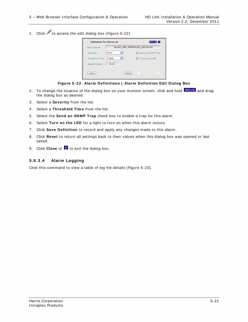
5 – Web Browser Interface Configuration & Operation HD Link Installation & Operation Manual Version 2.2, December 2011
Harris Corporation 5-21 Intraplex Products
1. Click to access the edit dialog box (Figure 5-22).
Figure 5-22. Alarm Definitions | Alarm Definition Edit Dialog Box
2. To change the location of the dialog box on your monitor screen, click and hold and drag the dialog box as desired.
3. Select a Severity from the list.
4. Select a Threshold Time from the list.
5. Select the Send an SNMP Trap check box to enable a trap for this alarm.
6. Select Turn on the LED for a light to turn on when this alarm occurs.
7. Click Save Definition to record and apply any changes made to this alarm.
8. Click Reset to return all settings back to their values when this dialog box was opened or last saved.
9. Click Close or to exit the dialog box.
5.6.3.4 Alarm Logging
Click this command to view a table of log file details (Figure 5-23).
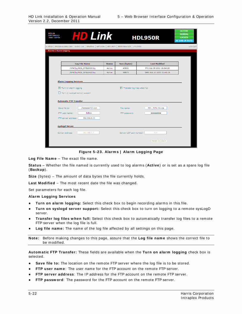
HD Link Installation & Operation Manual 5 – Web Browser Interface Configuration & Operation Version 2.2, December 2011
5-22 Harris Corporation Intraplex Products
Figure 5-23. Alarms | Alarm Logging Page
Log File Name – The exact file name.
Status – Whether the file named is currently used to log alarms (Active) or is set as a spare log file (Backup).
Size (bytes) – The amount of data bytes the file currently holds.
Last Modified – The most recent date the file was changed.
Set parameters for each log file.
Alarm Logging Services
● Turn on alarm logging: Select this check box to begin recording alarms in this file.
● Turn on syslogd server support: Select this check box to turn on logging to a remote sysLogD server.
● Transfer log files when full: Select this check box to automatically transfer log files to a remote FTP server when the log file is full.
● Log file name: The name of the log file affected by all settings on this page.
Note: Before making changes to this page, assure that the Log file name shows the correct file to be modified.
Automatic FTP Transfer: These fields are available when the Turn on alarm logging check box is selected.
● Save file to: The location on the remote FTP server where the log file is to be stored.
● FTP user name: The user name for the FTP account on the remote FTP server.
● FTP server address: The IP address for the FTP account on the remote FTP server.
● FTP password: The password for the FTP account on the remote FTP server.
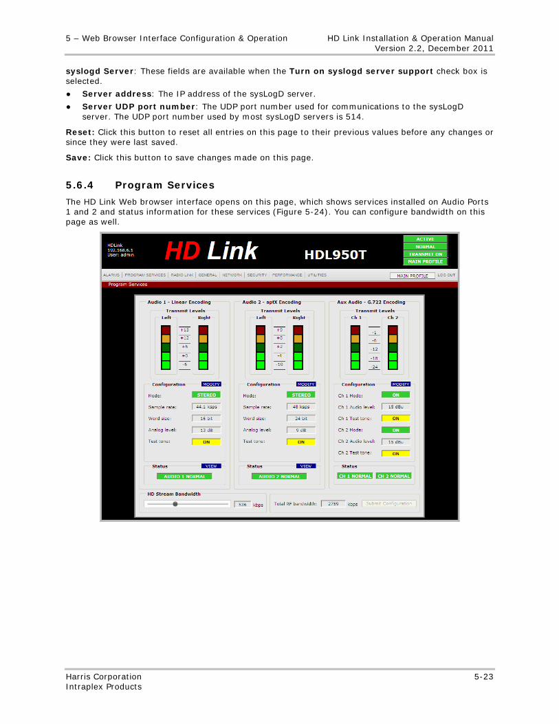
5 – Web Browser Interface Configuration & Operation HD Link Installation & Operation Manual Version 2.2, December 2011
Harris Corporation 5-23 Intraplex Products
syslogd Server: These fields are available when the Turn on syslogd server support check box is selected.
● Server address: The IP address of the sysLogD server.
● Server UDP port number: The UDP port number used for communications to the sysLogD server. The UDP port number used by most sysLogD servers is 514.
Reset: Click this button to reset all entries on this page to their previous values before any changes or since they were last saved.
Save: Click this button to save changes made on this page.
5.6.4 Program Services
The HD Link Web browser interface opens on this page, which shows services installed on Audio Ports 1 and 2 and status information for these services (Figure 5-24). You can configure bandwidth on this page as well.
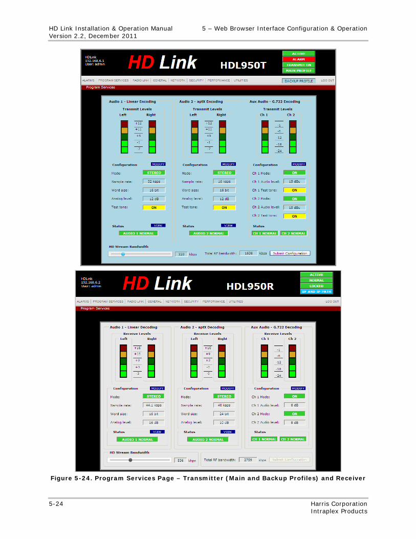
HD Link Installation & Operation Manual 5 – Web Browser Interface Configuration & Operation Version 2.2, December 2011
5-24 Harris Corporation Intraplex Products
Figure 5-24. Program Services Page – Transmitter (Main and Backup Profiles) and Receiver
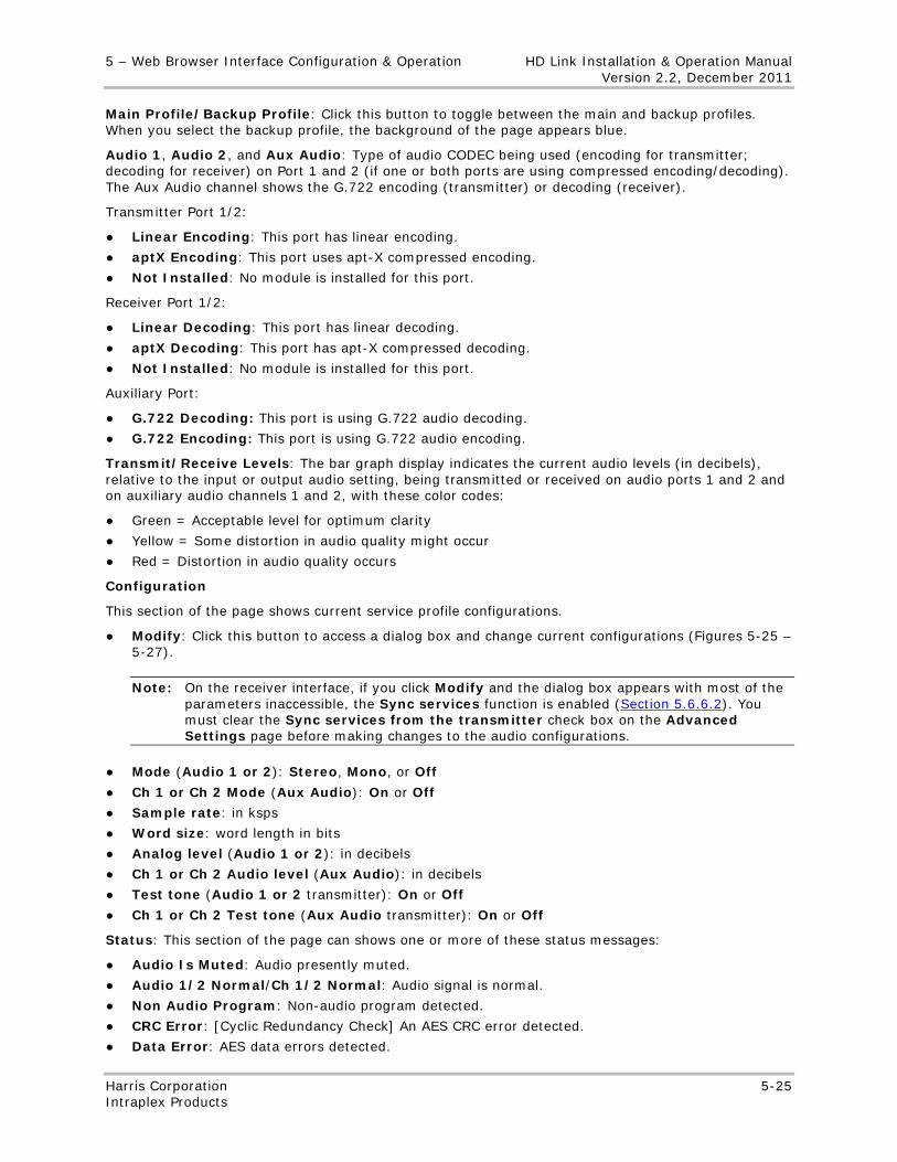
5 – Web Browser Interface Configuration & Operation HD Link Installation & Operation Manual Version 2.2, December 2011
Harris Corporation 5-25 Intraplex Products
Main Profile/Backup Profile: Click this button to toggle between the main and backup profiles. When you select the backup profile, the background of the page appears blue.
Audio 1, Audio 2, and Aux Audio: Type of audio CODEC being used (encoding for transmitter; decoding for receiver) on Port 1 and 2 (if one or both ports are using compressed encoding/decoding). The Aux Audio channel shows the G.722 encoding (transmitter) or decoding (receiver).
Transmitter Port 1/2:
● Linear Encoding: This port has linear encoding.
● aptX Encoding: This port uses apt-X compressed encoding.
● Not Installed: No module is installed for this port.
Receiver Port 1/2:
● Linear Decoding: This port has linear decoding.
● aptX Decoding: This port has apt-X compressed decoding.
● Not Installed: No module is installed for this port.
Auxiliary Port:
● G.722 Decoding: This port is using G.722 audio decoding.
● G.722 Encoding: This port is using G.722 audio encoding.
Transmit/Receive Levels: The bar graph display indicates the current audio levels (in decibels), relative to the input or output audio setting, being transmitted or received on audio ports 1 and 2 and on auxiliary audio channels 1 and 2, with these color codes:
● Green = Acceptable level for optimum clarity
● Yellow = Some distortion in audio quality might occur
● Red = Distortion in audio quality occurs
Configuration
This section of the page shows current service profile configurations.
● Modify: Click this button to access a dialog box and change current configurations (Figures 5-25 – 5-27).
Note: On the receiver interface, if you click Modify and the dialog box appears with most of the parameters inaccessible, the Sync services function is enabled (Section 5.6.6.2). You must clear the Sync services from the transmitter check box on the Advanced Settings page before making changes to the audio configurations.
● Mode (Audio 1 or 2): Stereo, Mono, or Off
● Ch 1 or Ch 2 Mode (Aux Audio): On or Off
● Sample rate: in ksps
● Word size: word length in bits
● Analog level (Audio 1 or 2): in decibels
● Ch 1 or Ch 2 Audio level (Aux Audio): in decibels
● Test tone (Audio 1 or 2 transmitter): On or Off
● Ch 1 or Ch 2 Test tone (Aux Audio transmitter): On or Off
Status: This section of the page can shows one or more of these status messages:
● Audio Is Muted: Audio presently muted.
● Audio 1/2 Normal/Ch 1/2 Normal: Audio signal is normal.
● Non Audio Program: Non-audio program detected.
● CRC Error: [Cyclic Redundancy Check] An AES CRC error detected.
● Data Error: AES data errors detected.
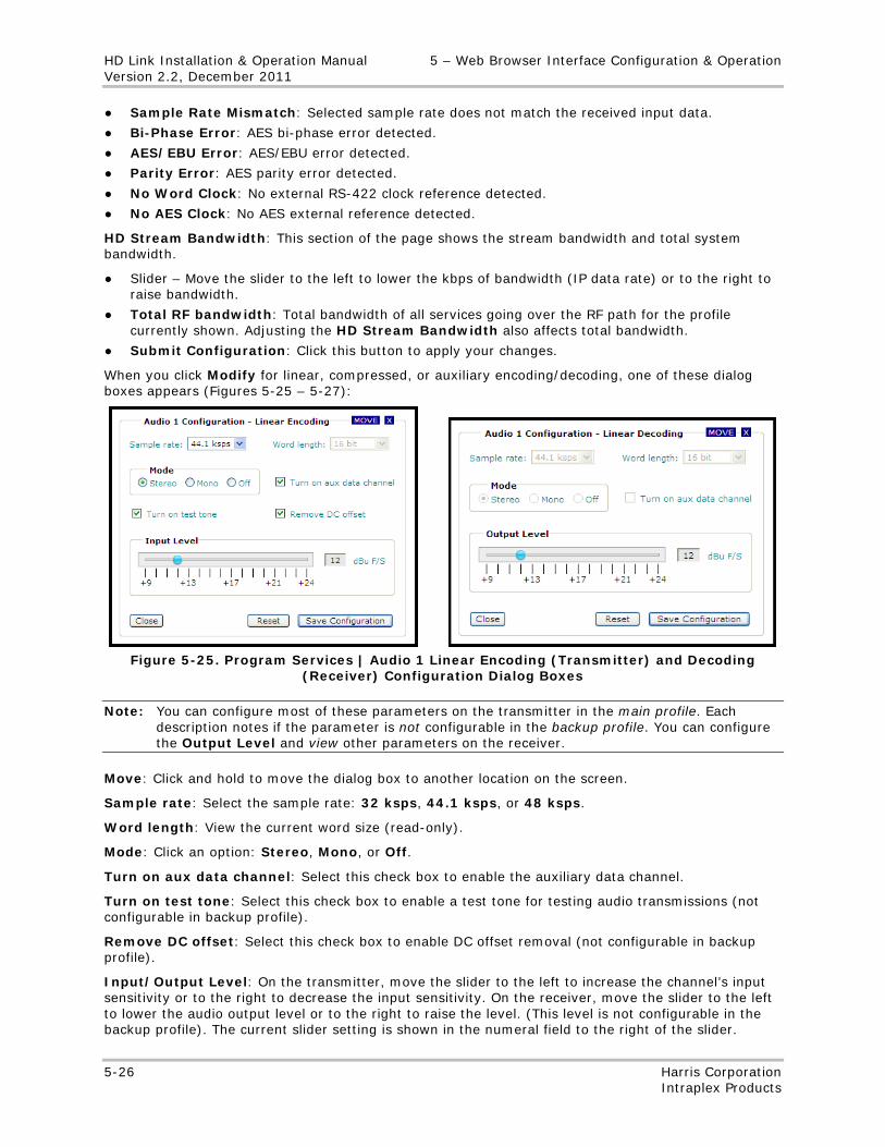
HD Link Installation & Operation Manual 5 – Web Browser Interface Configuration & Operation Version 2.2, December 2011
5-26 Harris Corporation Intraplex Products
● Sample Rate Mismatch: Selected sample rate does not match the received input data.
● Bi-Phase Error: AES bi-phase error detected.
● AES/EBU Error: AES/EBU error detected.
● Parity Error: AES parity error detected.
● No Word Clock: No external RS-422 clock reference detected.
● No AES Clock: No AES external reference detected.
HD Stream Bandwidth: This section of the page shows the stream bandwidth and total system bandwidth.
● Slider – Move the slider to the left to lower the kbps of bandwidth (IP data rate) or to the right to raise bandwidth.
● Total RF bandwidth: Total bandwidth of all services going over the RF path for the profile currently shown. Adjusting the HD Stream Bandwidth also affects total bandwidth.
● Submit Configuration: Click this button to apply your changes.
When you click Modify for linear, compressed, or auxiliary encoding/decoding, one of these dialog boxes appears (Figures 5-25 – 5-27):
Figure 5-25. Program Services | Audio 1 Linear Encoding (Transmitter) and Decoding
(Receiver) Configuration Dialog Boxes
Note: You can configure most of these parameters on the transmitter in the main profile. Each description notes if the parameter is not configurable in the backup profile. You can configure the Output Level and view other parameters on the receiver.
Move: Click and hold to move the dialog box to another location on the screen.
Sample rate: Select the sample rate: 32 ksps, 44.1 ksps, or 48 ksps.
Word length: View the current word size (read-only).
Mode: Click an option: Stereo, Mono, or Off.
Turn on aux data channel: Select this check box to enable the auxiliary data channel.
Turn on test tone: Select this check box to enable a test tone for testing audio transmissions (not configurable in backup profile).
Remove DC offset: Select this check box to enable DC offset removal (not configurable in backup profile).
Input/Output Level: On the transmitter, move the slider to the left to increase the channel’s input sensitivity or to the right to decrease the input sensitivity. On the receiver, move the slider to the left to lower the audio output level or to the right to raise the level. (This level is not configurable in the backup profile). The current slider setting is shown in the numeral field to the right of the slider.
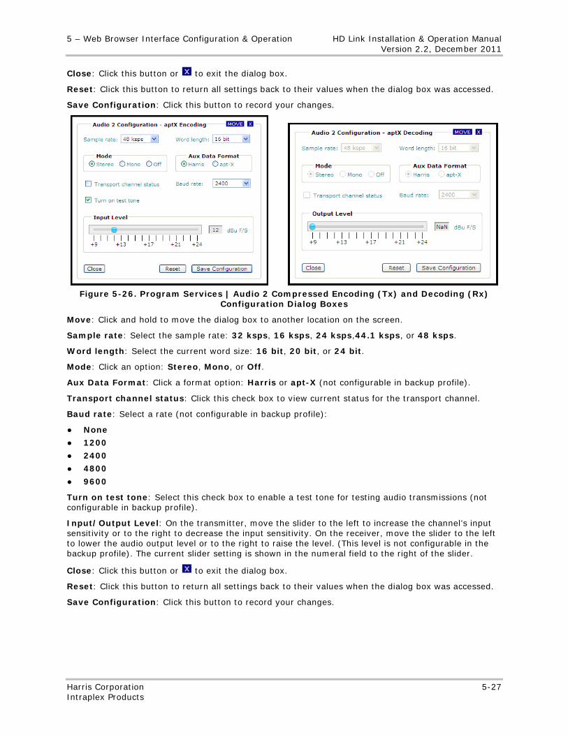
5 – Web Browser Interface Configuration & Operation HD Link Installation & Operation Manual Version 2.2, December 2011
Harris Corporation 5-27 Intraplex Products
Close: Click this button or to exit the dialog box.
Reset: Click this button to return all settings back to their values when the dialog box was accessed.
Save Configuration: Click this button to record your changes.
Figure 5-26. Program Services | Audio 2 Compressed Encoding (Tx) and Decoding (Rx)
Configuration Dialog Boxes
Move: Click and hold to move the dialog box to another location on the screen.
Sample rate: Select the sample rate: 32 ksps, 16 ksps, 24 ksps,44.1 ksps, or 48 ksps.
Word length: Select the current word size: 16 bit, 20 bit, or 24 bit.
Mode: Click an option: Stereo, Mono, or Off.
Aux Data Format: Click a format option: Harris or apt-X (not configurable in backup profile).
Transport channel status: Click this check box to view current status for the transport channel.
Baud rate: Select a rate (not configurable in backup profile):
● None
● 1200
● 2400
● 4800
● 9600
Turn on test tone: Select this check box to enable a test tone for testing audio transmissions (not configurable in backup profile).
Input/Output Level: On the transmitter, move the slider to the left to increase the channel’s input sensitivity or to the right to decrease the input sensitivity. On the receiver, move the slider to the left to lower the audio output level or to the right to raise the level. (This level is not configurable in the backup profile). The current slider setting is shown in the numeral field to the right of the slider.
Close: Click this button or to exit the dialog box.
Reset: Click this button to return all settings back to their values when the dialog box was accessed.
Save Configuration: Click this button to record your changes.
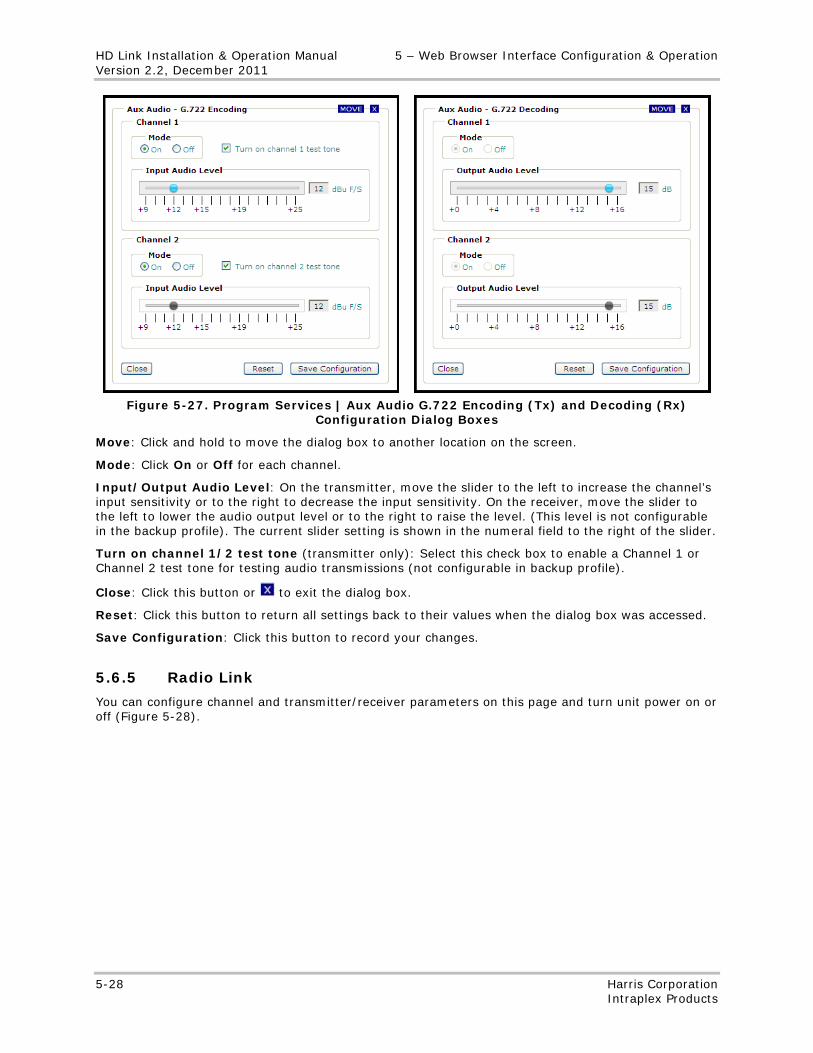
HD Link Installation & Operation Manual 5 – Web Browser Interface Configuration & Operation Version 2.2, December 2011
5-28 Harris Corporation Intraplex Products
Figure 5-27. Program Services | Aux Audio G.722 Encoding (Tx) and Decoding (Rx)
Configuration Dialog Boxes
Move: Click and hold to move the dialog box to another location on the screen.
Mode: Click On or Off for each channel.
Input/Output Audio Level: On the transmitter, move the slider to the left to increase the channel’s input sensitivity or to the right to decrease the input sensitivity. On the receiver, move the slider to the left to lower the audio output level or to the right to raise the level. (This level is not configurable in the backup profile). The current slider setting is shown in the numeral field to the right of the slider.
Turn on channel 1/2 test tone (transmitter only): Select this check box to enable a Channel 1 or Channel 2 test tone for testing audio transmissions (not configurable in backup profile).
Close: Click this button or to exit the dialog box.
Reset: Click this button to return all settings back to their values when the dialog box was accessed.
Save Configuration: Click this button to record your changes.
5.6.5 Radio Link
You can configure channel and transmitter/receiver parameters on this page and turn unit power on or off (Figure 5-28).
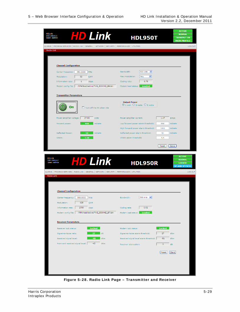
5 – Web Browser Interface Configuration & Operation HD Link Installation & Operation Manual Version 2.2, December 2011
Harris Corporation 5-29 Intraplex Products
Figure 5-28. Radio Link Page – Transmitter and Receiver
HD Link Installation & Operation Manual 5 – Web Browser Interface Configuration & Operation Version 2.2, December 2011
5-30 Harris Corporation Intraplex Products
Channel Configuration
● Center frequency: Type the center frequency between 942 and 960 MHz.
● Modulation: The current modulation the system is using, in QAM. If the receiver cannot locate a signal, a yellow Acquiring message appears in this field.
● Information rate: The rate of information being transmitted or received in kbps.
● Modem config file: The name of the configuration file in use by the RF modem.
● Bandwidth: Select a bandwidth from the list:
• 200 kHz • 250 kHz • 300 kHz • 375 kHz • 500 kHz
● Max modulation (transmitter): Select a maximum modulation level on the transmitter:
• Any – Any modulation is allowed. • 16 QAM • 32 QAM • 64 QAM • 128 QAM • 256 QAM
● Coding rate: The percentage of bandwidth not allocated to forward error correction (FEC). If the receiver cannot locate a signal, a yellow Acquiring message appears in this field.
● Modem load status: Loaded (green) or Acquiring (yellow)
Transmitter Parameters
● On/Off: Click this button to turn the transmitter power on or off.
● Turn off the PA when idle: If the primary path is IP, select this check box and click Save if you want the system to turn off the power amplifier if no services are currently going over the RF path. With this setting, you can save power when the RF path is a backup path and not used by any of the services.
Notes: You cannot turn the PA on or off if this check box is select. Keep this check box cleared if you want to manually turn the PA on or off. This control does not exist for a transmitter configured as a repeater.
● Power amplifier voltage: Current amplifier voltage.
● Forward power: Measured actual output power, in watts.
● Reflected power: Level of output power being reflected back to the transmitter, in watts.
● VSWR: Current Voltage Standing Wave Ratio.
● Output Power: Click an option to configure the transmitter output power:
• 1 watt • 2 watts • 5 watts
● Power amplifier current: Current value of the power amplifier.
● Low forward power alarm threshold: Sets the lowest possible value, in milliwatts, for the forward power before an alarm is generated. The low forward power alarm threshold setting must be between 0 and 7000, inclusive.
● High forward power alarm threshold: Sets the highest possible value, in milliwatts, for the forward power before an alarm is generated. The high forward power alarm threshold setting must be between 0 and 7000, inclusive.
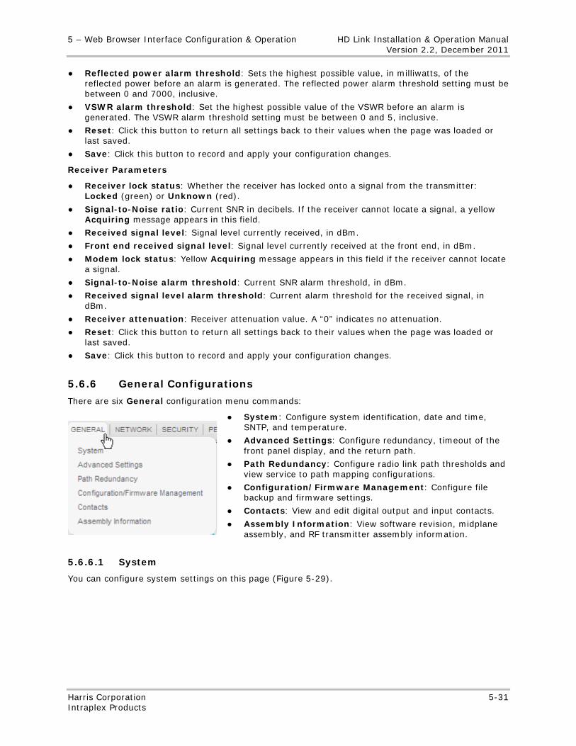
5 – Web Browser Interface Configuration & Operation HD Link Installation & Operation Manual Version 2.2, December 2011
Harris Corporation 5-31 Intraplex Products
● Reflected power alarm threshold: Sets the highest possible value, in milliwatts, of the reflected power before an alarm is generated. The reflected power alarm threshold setting must be between 0 and 7000, inclusive.
● VSWR alarm threshold: Set the highest possible value of the VSWR before an alarm is generated. The VSWR alarm threshold setting must be between 0 and 5, inclusive.
● Reset: Click this button to return all settings back to their values when the page was loaded or last saved.
● Save: Click this button to record and apply your configuration changes.
Receiver Parameters
● Receiver lock status: Whether the receiver has locked onto a signal from the transmitter: Locked (green) or Unknown (red).
● Signal-to-Noise ratio: Current SNR in decibels. If the receiver cannot locate a signal, a yellow Acquiring message appears in this field.
● Received signal level: Signal level currently received, in dBm.
● Front end received signal level: Signal level currently received at the front end, in dBm.
● Modem lock status: Yellow Acquiring message appears in this field if the receiver cannot locate a signal.
● Signal-to-Noise alarm threshold: Current SNR alarm threshold, in dBm.
● Received signal level alarm threshold: Current alarm threshold for the received signal, in dBm.
● Receiver attenuation: Receiver attenuation value. A “0” indicates no attenuation.
● Reset: Click this button to return all settings back to their values when the page was loaded or last saved.
● Save: Click this button to record and apply your configuration changes.
5.6.6 General Configurations
There are six General configuration menu commands:
● System: Configure system identification, date and time, SNTP, and temperature.
● Advanced Settings: Configure redundancy, timeout of the front panel display, and the return path.
● Path Redundancy: Configure radio link path thresholds and view service to path mapping configurations.
● Configuration/Firmware Management: Configure file backup and firmware settings.
● Contacts: View and edit digital output and input contacts.
● Assembly Information: View software revision, midplane assembly, and RF transmitter assembly information.
5.6.6.1 System
You can configure system settings on this page (Figure 5-29).
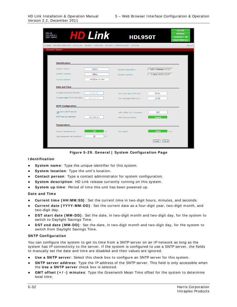
HD Link Installation & Operation Manual 5 – Web Browser Interface Configuration & Operation Version 2.2, December 2011
5-32 Harris Corporation Intraplex Products
Figure 5-29. General | System Configuration Page
Identification
● System name: Type the unique identifier for this system.
● System location: Type the unit’s location.
● Contact person: Type a contact administrator for system configuration.
● System description: HD Link release currently running on this system.
● System up time: Period of time this unit has been powered up.
Date and Time
● Current time (HH:MM:SS): Set the current time in two-digit hours, minutes, and seconds.
● Current date (YYYY-MM-DD): Set the current date as a four-digit year, two-digit month, and two-digit day.
● DST start date (MM-DD): Set the date, in two-digit month and two-digit day, for the system to switch to Daylight Savings Time.
● DST end date (MM-DD): Set the date, in two-digit month and two-digit day, for the system to switch from Daylight Savings Time.
SNTP Configuration
You can configure the system to get its time from a SNTP server on an IP network as long as the system has IP connectivity to the server. If the system is configured to use a SNTP server, the fields to manually set the date and time are disabled and their values are ignored.
● Use a SNTP server: Select this check box to configure an SNTP server for this system.
● SNTP server address: Type the IP address of the SNTP server. This field is only accessible when the Use a SNTP server check box is selected.
● GMT offset (+/-) minutes: Type the Greenwich Mean Time offset for the system to determine local time.
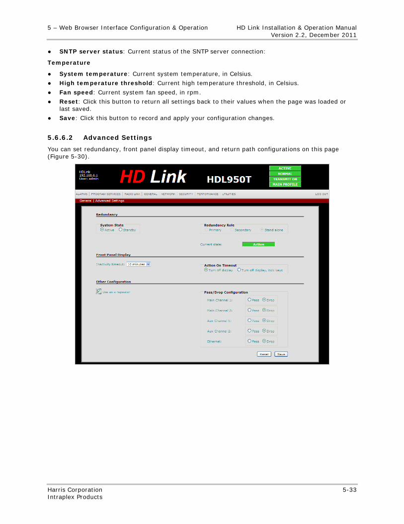
5 – Web Browser Interface Configuration & Operation HD Link Installation & Operation Manual Version 2.2, December 2011
Harris Corporation 5-33 Intraplex Products
● SNTP server status: Current status of the SNTP server connection:
Temperature
● System temperature: Current system temperature, in Celsius.
● High temperature threshold: Current high temperature threshold, in Celsius.
● Fan speed: Current system fan speed, in rpm.
● Reset: Click this button to return all settings back to their values when the page was loaded or last saved.
● Save: Click this button to record and apply your configuration changes.
5.6.6.2 Advanced Settings
You can set redundancy, front panel display timeout, and return path configurations on this page (Figure 5-30).
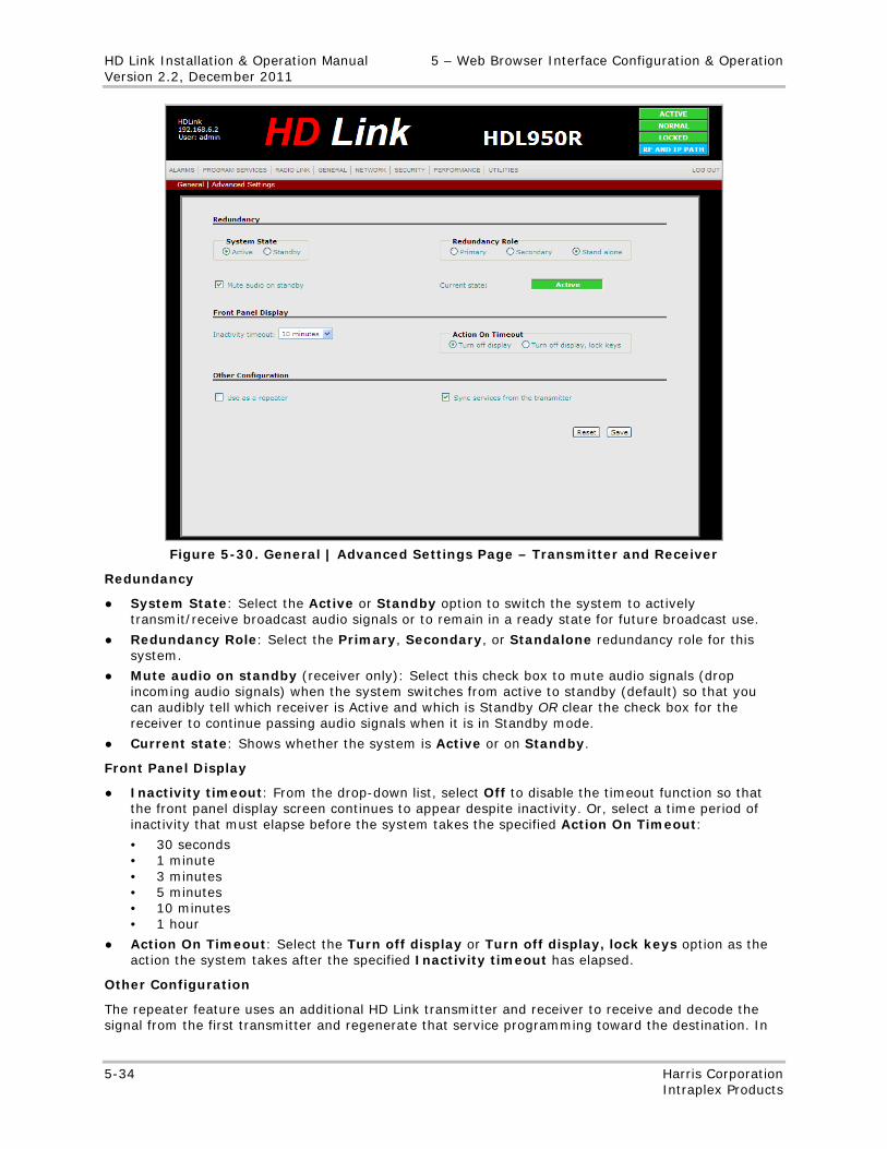
HD Link Installation & Operation Manual 5 – Web Browser Interface Configuration & Operation Version 2.2, December 2011
5-34 Harris Corporation Intraplex Products
Figure 5-30. General | Advanced Settings Page – Transmitter and Receiver
Redundancy
● System State: Select the Active or Standby option to switch the system to actively transmit/receive broadcast audio signals or to remain in a ready state for future broadcast use.
● Redundancy Role: Select the Primary, Secondary, or Standalone redundancy role for this system.
● Mute audio on standby (receiver only): Select this check box to mute audio signals (drop incoming audio signals) when the system switches from active to standby (default) so that you can audibly tell which receiver is Active and which is Standby OR clear the check box for the receiver to continue passing audio signals when it is in Standby mode.
● Current state: Shows whether the system is Active or on Standby.
Front Panel Display
● Inactivity timeout: From the drop-down list, select Off to disable the timeout function so that the front panel display screen continues to appear despite inactivity. Or, select a time period of inactivity that must elapse before the system takes the specified Action On Timeout:
• 30 seconds • 1 minute • 3 minutes • 5 minutes • 10 minutes • 1 hour
● Action On Timeout: Select the Turn off display or Turn off display, lock keys option as the action the system takes after the specified Inactivity timeout has elapsed.
Other Configuration
The repeater feature uses an additional HD Link transmitter and receiver to receive and decode the signal from the first transmitter and regenerate that service programming toward the destination. In
5 – Web Browser Interface Configuration & Operation HD Link Installation & Operation Manual Version 2.2, December 2011
Harris Corporation 5-35 Intraplex Products
repeater mode, the receiver forwards the incoming audio and data packets to the HD interface. The transmitting repeater functionality depends on the configuration of each service type (main channels 1 and 2, auxiliary channels 1 and 2, and the Ethernet) is configured. You can set each service type to either pass or “drop” (do not pass along) audio at the transmitter. Therefore, the transmitting repeater system can either play incoming audio and pass it along, play incoming audio but drop (not pass) it, or simply pass the incoming audio. Audio channels selected to pass audio play it as well, as long as there are channel modules in the system to play the audio. Audio signals always play out of auxiliary channels.
● Use as a repeater: Select this check box to enable the Repeater mode for this unit.
● Pass/Drop Configuration (transmitter only): These configurations are available when the Use as a repeater check box is selected. For each service type, select the Pass option for the transmitter to pass audio or select the Drop option if you do not want audio to be passed. Click Reset to revert back to the previous setting. Click Save to record and apply your selection.
Note: In repeater mode, the HD Link system supports end-to-end path redundancy but is not a participant in path redundancy. Therefore, if you wish to enable IP Path Redundancy (Section 5.6.6.3) for each segment of a 2- or multi-hop system, do not enable Repeater mode; instead, configure each frequency pair as an independent system.
Sync services from the transmitter (receiver only): Select this check box for the receiver to sync with the transmitter and obtain any audio configuration changes and any return path IP address from the transmitter. The Automatic Configuration function allows the transmitter to send this information to the receiver at a rate of once per second:
● Audio channel parameters
• On or off • Sampling rate • Word length • Stereo or mono mode • Linear aux data control • Channel status
● Auxiliary audio channel state – On or off
● LAN port IP address for return path tunneling
With this function on (check box selected), you only need to change these parameters on the transmitter, and the changes are automatically made on the receiver.
Note: You need to clear the Sync services from the transmitter check box before making any changes to the Audio Configuration parameters on the Program Services page.
Reset: Click this button to return all settings back to their values when the page was loaded or last saved.
Save: Click this button to record and apply changes.
5.6.6.3 Path Redundancy
You can set various parameters for the IP path redundancy feature, including radio link path thresholds and the forward path jitter amount, and view service to path mapping configurations on this page (Figure 5-31).
Note: You can view path redundancy status on the front panel display (Section 4.4.4.10). Use the General | Path Redundancy page to configure the parameters (Figure 5-31).
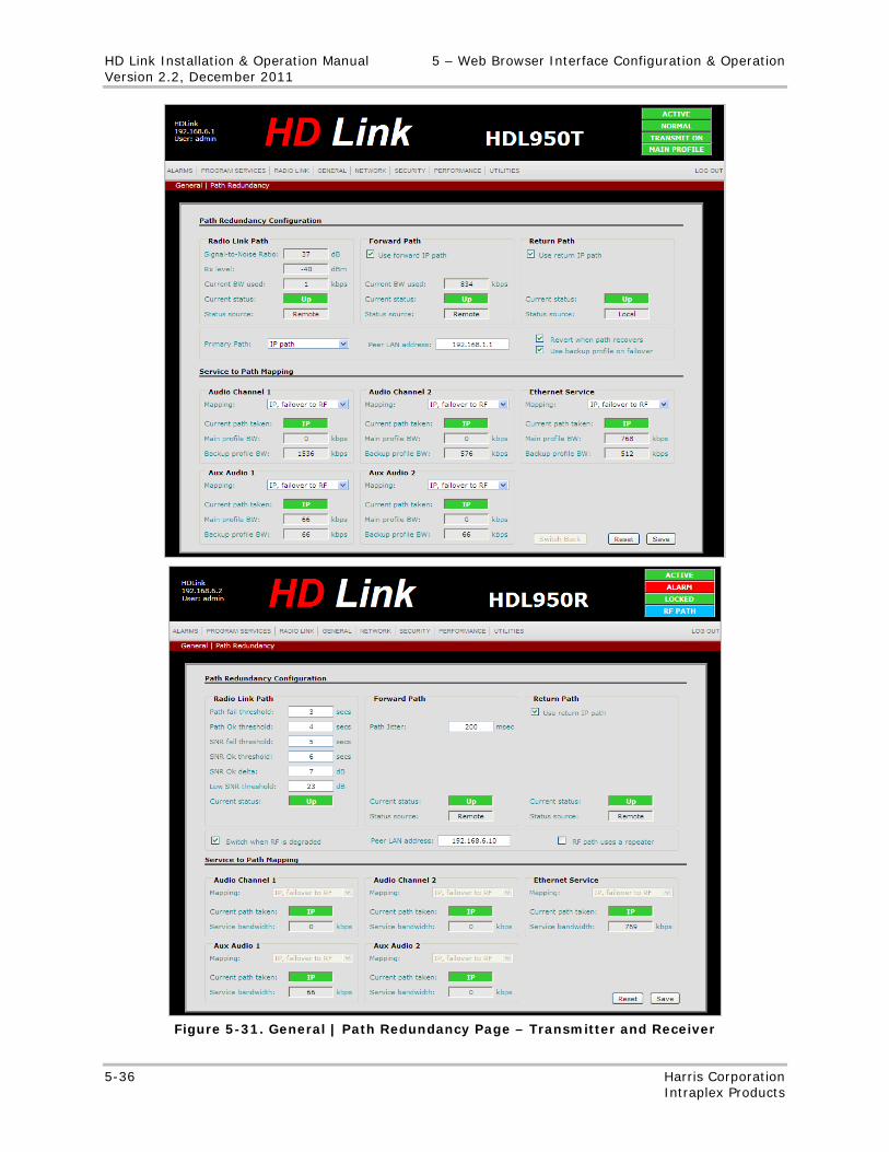
HD Link Installation & Operation Manual 5 – Web Browser Interface Configuration & Operation Version 2.2, December 2011
5-36 Harris Corporation Intraplex Products
Figure 5-31. General | Path Redundancy Page – Transmitter and Receiver
5 – Web Browser Interface Configuration & Operation HD Link Installation & Operation Manual Version 2.2, December 2011
Harris Corporation 5-37 Intraplex Products
Path Redundancy Configuration
Radio Link Path:
● Signal-to-Noise Ratio (transmitter only): The RF SNR from the receiver via the path control message, in dB.
● Rx level (transmitter only): The RF level from the receiver via the path control message, in dBm.
● Current BW used (transmitter only): The total bandwidth of all services being transmitted over the RF path, including overhead.
● Status source (transmitter only): Whether the status for the radio path has been determined locally or from the receiver.
● Path fail threshold (receiver only): The number of consecutive seconds that the modem needs to be unlocked before declaring RF path failure.
● Path Ok threshold (receiver only): The number of consecutive seconds that the modem needs to be locked before declaring the RF path okay.
● SNR fail threshold (receiver only): The number of consecutive seconds that the modem needs to be in low SNR before declaring the RF path degraded.
● SNR Ok threshold (receiver only): The number of consecutive seconds that the modem needs to be above low SNR before transitioning the RF path from degraded to okay.
● SNR Ok delta (receiver only): Hysteresis applied to the SNR before transitioning the state from degraded back to okay, in dB.
● Low SNR threshold (receiver only): The level of dB at which the SNR is considered low.
● Current status: Whether the RF is currently Up, Down, or Unknown (set on the transmitter side when receiver messages are not arriving and there are no local alarms).
Forward Path:
● Use forward IP path (transmitter only): Select this check box to enable the forward IP path.
● Current BW used (transmitter only): The total bandwidth of all services being transmitted over the forward path, including overhead.
● Path Jitter (receiver only): The maximum jitter that needs to be compensated in the forward IP path direction, in milliseconds (msec). The default is 300 msec. The supported range is from 200 msec to 1 second.
● Current status: Whether the forward path is currently Up, Down, or Unknown (set on the transmitter side when receiver messages are not arriving and there are no local alarms).
● Status source: Whether the status for the forward path has been determined locally or from the receiver.
Notes: The path redundancy feature is turned off if the Use forward IP path and Use return IP path check boxes are cleared (not selected). When the Use return IP path check box is selected, the receiver return path setting should match the transmitter setting. If the Use return IP path is selected but the Use forward IP path is not selected, you still have the advantage of receiving status and alarm feedback of the entire RF path from the receiver to the transmitter.
Return Path:
● Use return IP path: Select this check box to enable the return IP path.
● Current status: Whether the return path is currently Up, Down, or Unknown (set on the transmitter side when receiver messages are not arriving and there are no local alarms).
● Status source: Whether the status for the return path has been determined locally or from the receiver.
Primary Path (transmitter only): Select the primary path for the system: RF path or IP path.
HD Link Installation & Operation Manual 5 – Web Browser Interface Configuration & Operation Version 2.2, December 2011
5-38 Harris Corporation Intraplex Products
Switch when RF is degraded (receiver only): Select this check box to enable RF path degradation reporting (with associated SNR thresholds) to the transmitter. When you enable use of the backup profile (that is, select the Use backup profile on failover check box), the system switches to that profile when the path degrades.
Peer LAN Address: The IP address of the LAN interface.
Revert when path recovers (transmitter only): Select this check box to enable reversion after failover. When this check box is selected, the system automatically reverts to the main profile and path when the primary path is restored. When this check box is cleared (not selected), the system remains on the backup profile and path even when the primary path recovers; you then need to perform a manual switchback or enable reversion for the system to revert to the normal profile and path.
Use backup profile on failover (transmitter only): Select this check box to enable the system to switch to the backup profile if the main profile fails.
Note: Backup profile use is optional. You can utilize the path redundancy feature without the backup profile by using the Service to Path Mapping settings to configure how the services are transported. Use this profile when you want to keep services going with less bitrate.
RF path uses a repeater (receiver only): Select this check box if the RF path contains a repeater. This setting tells the receiver to rely on the presence of in-band messages on the RF path to determine if there is a break in the RF path. When you select this check box, the end receiver detects and reports failure of any of the intermediate links.
Service to Path Mapping
While the main and backup service profiles define the attribute of a service, the service path configuration defines how those services are transported. Therefore, regardless of whether the main or backup profile is active, the service path settings dictate how the services are transported. At a system level, both the service profiles and service path mapping work in conjunction to provide dynamic adjustment of total information rate and path switching.
Audio Channel 1/ Audio Channel 2/Ethernet Service/ Audio Aux 1/ Audio Aux 2:
● Mapping (configured on transmitter; read-only on receiver): Select the path type to map the service to:
• RF only – The service is only transmitted over the RF path in all conditions. • IP only – The service is only transmitted over the IP path in all conditions. • RF, failover to IP – Available when the Primary Path is set to RF, this setting indicates that
the service is to failover to the IP path when the RF path fails. • IP, failover to RF – Available when the Primary Path is set to IP, this setting indicates that
the service is to failover to the RF path when the IP path fails. • RF and IP – This setting indicates that the service is continuously sent over both the RF and
the IP paths in all conditions. The receiver automatically performs the failover. This setting provides the most reliable service, as the failover to the backup path is almost instantaneous.
• IP, drop if RF fails – Available when the Primary Path is set to RF, this setting indicates that the service is only transmitted on the IP path and only if the RF path is okay. You can use this setting for low priority services, when other higher priority services are set to RF, failover to IP. Then, if the RF fails, the system drops the low priority services and only transmits the higher priority services over IP.
• RF, drop if IP fails – Available when the Primary Path is set to IP, this setting indicates that the service is only transmitted on the RF path and only if the IP path is okay. You can use this setting for low priority services, when other higher priority services are set to IP, failover to RF. Then, if the IP fails, the system drops the low priority services and only transmits the higher priority services over RF.
5 – Web Browser Interface Configuration & Operation HD Link Installation & Operation Manual Version 2.2, December 2011
Harris Corporation 5-39 Intraplex Products
Note: Take care when using this setting, as the RF path’s modem parameter is dynamically set based on the required information rate. The services getting stopped due to this setting should be higher in capacity than the higher priority services that will take over their capacity. Generally, when using the IP path as the primary and a reduced RF path as a backup, it is safer to use a separate backup profile which becomes active when the services switch to the RF path. When this setting is used, the system performs the necessary check to assure the entire backup profile fits on the RF path.
● Current path taken: This service’s current path: RF, IP, RF and IP, None. The current path depends on the service’s path map configuration as well as the status of the primary path.
● Main profile BW: The bandwidth of the service, excluding overhead, as configured in the main profile.
● Backup profile BW: The bandwidth of the service, excluding overhead, as configured in the backup profile.
Switch Back (transmitter only): When reversion is disabled (that is, the Revert when path recovers check box is selected), you can click this button to revert back to the primary path once the path’s status is restored.
Reset: Click this button to return all settings back to their values when the page was loaded or last saved.
Save: Click this button to record and apply changes.
Use of Service Profiles and Path Capacities
The HD Link system supports the use of a main and a backup service profile. Within these profiles, the attributes of the services are defined, such as
• Audio sample rates. • Stereo or mono mode. • Ethernet data rate. • Ability to turn a service off.
The service profile settings factor into the required information rate. Since both the main and backup service profiles are independent, they can have different information rate requirements. The system automatically checks if the service profile exceeds the physical limit of the mapped path. For example, if the services of the main or backup service profiles are to go over the RF path, the system checks whether the RF bandwidth can accommodate the services before accepting the user settings. Presently, there is no capacity check performed when going over the IP path. Instead, the system provides the required bitrates of each individual service, and you then need to manually figure out and adjust the profile if it exceeds the data rate capacity of the IP path.
The system uses the main service profile when operating on the primary path. When the backup service profile is configured, the system switches to the backup profile when the primary path fails or degrades.
Note: Use of the backup service profile should be carefully evaluated versus service path configuration. When the service profile switch occurs (which requires changing a particular audio service attribute, a very brief audible artifact may be heard on that channel until the new settings are synchronized between the two ends. However, the transition is audibly smoother when switching service paths. Therefore, if a use case scenario can be satisfied by service path configuration, that configuration is the preferred method.
First Sample Scenario: RF Path as Primary, IP Path as Backup
There are many different scenarios for setting path redundancy. This procedure assumes perhaps the most common scenario: You have a licensed RF STL primary path along with an IP path that
HD Link Installation & Operation Manual 5 – Web Browser Interface Configuration & Operation Version 2.2, December 2011
5-40 Harris Corporation Intraplex Products
can be used as a backup. To configure the path redundancy feature for this scenario, perform these steps:
1. On the Path Redundancy page, select RF path from the Primary Path drop-down list.
2. For all non-failover (lower priority) services, from the Mapping drop-down list, select either RF Only or IP, drop if RF fails.
3. For all failover (higher priority) services, from the Mapping drop-down list, select either RF, failover to IP or RF and IP.
When failover occurs, if all the services going over the IP path exceed the total available capacity, the backup profile must be used to change the attributes of the services to fit into the IP path capacity.
Second Sample Scenario: RF Path Only, IP Return Path Available
The second scenario assumes you have an IP path from the transmitter site back to the studio, but the path has insufficient bandwidth or is not reliable enough to be used for backup. In this case, you can use the return IP path to send back status information on the RF receive signal reaching the transmitter site and configure a backup profile to be used when environmental or other conditions have degraded the RF link to the point where it can no longer support all desired services. To configure the path redundancy feature for this scenario, perform these steps:
1. On the transmitter’s Path Redundancy page, select RF path from the Primary Path drop-down list.
2. On the transmitter’s Program Services page, click Backup Profile on the navigation bar. The screen has a blue tint, indicating the backup profile configuration view.
3. Click Modify at Audio 1 Configuration to access the Audio 1 Configuration dialog box.
4. To set the backup profile Audio 1 for a significantly lower bandwidth than the main profile
a. Select a lower Sample rate from the drop-down list. b. At Mode, click the Mono option. c. Clear the Turn on aux data channel check box.
5. Click Modify at Audio 2 Configuration to access the Audio 2 Configuration dialog box.
6. Repeat Step 4 to configure Audio 2 as well.
Third Sample Scenario: IP Path as Primary, RF Path as Backup
The final scenario assumes you use a leased line or a business class Internet connection and only use the RF STL as a backup. In this case, you have the option to keep the Power Amplifier (PA) in the standby state while the RF path is not used by any of the service path mapping. The system automatically controls the state of the PA based on the usage of the RF path. You then periodically turn on the PA to verify the RF path. To configure the path redundancy feature for this scenario, perform these steps:
1. On the Path Redundancy page, select IP path from the Primary Path drop-down list.
2. For all non-failover (lower priority) services, from the Mapping drop-down list, select either IP Only or RF, drop if IP fails.
3. For all failover (higher priority) services, from the Mapping drop-down list, select either IP, failover to RF or RF and IP.
When failover occurs, if all the services going over the RF path exceed the total available capacity, the backup profile must be used to change the attributes of the services to fit into the RF path capacity.
Path Redundancy Interworking with Repeater Systems
The path redundancy feature works with a repeater HD Link configuration. All service path settings are possible, including use of the main and backup service profiles. However, the IP path is
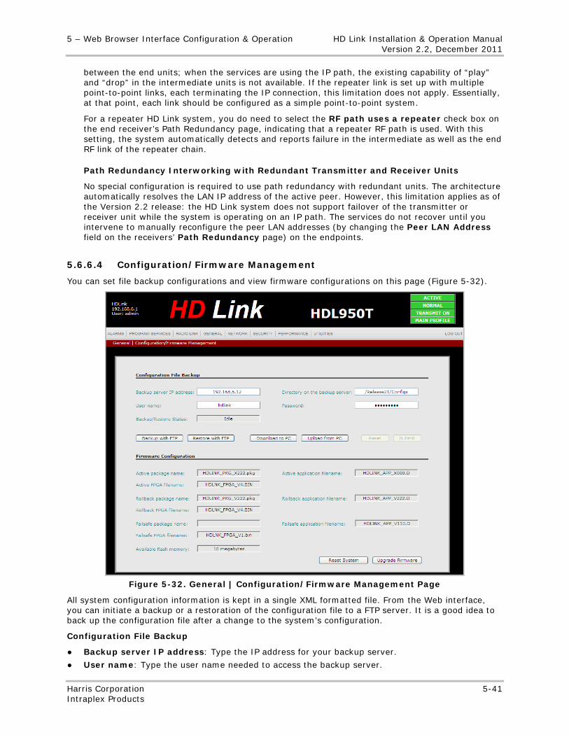
5 – Web Browser Interface Configuration & Operation HD Link Installation & Operation Manual Version 2.2, December 2011
Harris Corporation 5-41 Intraplex Products
between the end units; when the services are using the IP path, the existing capability of “play” and “drop” in the intermediate units is not available. If the repeater link is set up with multiple point-to-point links, each terminating the IP connection, this limitation does not apply. Essentially, at that point, each link should be configured as a simple point-to-point system.
For a repeater HD Link system, you do need to select the RF path uses a repeater check box on the end receiver’s Path Redundancy page, indicating that a repeater RF path is used. With this setting, the system automatically detects and reports failure in the intermediate as well as the end RF link of the repeater chain.
Path Redundancy Interworking with Redundant Transmitter and Receiver Units
No special configuration is required to use path redundancy with redundant units. The architecture automatically resolves the LAN IP address of the active peer. However, this limitation applies as of the Version 2.2 release: the HD Link system does not support failover of the transmitter or receiver unit while the system is operating on an IP path. The services do not recover until you intervene to manually reconfigure the peer LAN addresses (by changing the Peer LAN Address field on the receivers’ Path Redundancy page) on the endpoints.
5.6.6.4 Configuration/Firmware Management
You can set file backup configurations and view firmware configurations on this page (Figure 5-32).
Figure 5-32. General | Configuration/Firmware Management Page
All system configuration information is kept in a single XML formatted file. From the Web interface, you can initiate a backup or a restoration of the configuration file to a FTP server. It is a good idea to back up the configuration file after a change to the system’s configuration.
Configuration File Backup
● Backup server IP address: Type the IP address for your backup server.
● User name: Type the user name needed to access the backup server.
HD Link Installation & Operation Manual 5 – Web Browser Interface Configuration & Operation Version 2.2, December 2011
5-42 Harris Corporation Intraplex Products
● Backup/Restore Status: Status of the current backup or restore process, if any.
● Directory on the backup server: Type the location of the configuration file on the backup server directory.
● Password: Type the password needed to access the backup server.
● Backup with FTP: Click this button to back up your configuration to an FTP server.
● Restore with FTP: Click this button to restore your configuration to the backup configuration saved on an FTP server. Once a configuration is restored, the system automatically restarts.
● Download to PC: Click this button to download a configuration file to your PC.
● Upload from PC: Click this button to upload a configuration file from your PC.
● Reset: Click this button to return all settings back to their values when the page was loaded or last saved.
● Submit: Click this button to apply changes.
Note: You can only access the Reset or Submit buttons if you have made changes to this page. Likewise, you can only access the Backup Configuration or Restore Configuration buttons if you have made no changes to the page, submitted any changes, or reset (reversed) any changes to the page.
5 – Web Browser Interface Configuration & Operation HD Link Installation & Operation Manual Version 2.2, December 2011
Harris Corporation 5-43 Intraplex Products
Firmware Configuration
● Active package name: Software package name from which the currently used application software, FPGA firmware, modem profiles and boot ROM were extracted.
● Active FPGA filename: File name of the FPGA firmware currently in use.
● Active application filename: File name of the application software currently running.
● Rollback package name: Software package name from which the application software, FPGA firmware, modem profiles, and boot ROM are used prior to the installation of the active package were extracted.
● Rollback FPGA name: File name of the FPGA firmware most previously used.
● Rollback application filename: File name of the application software most recently used.
● Failsafe package name: Software package name from which the application software, FPGA firmware, modem profiles, and boot ROM are used if the active package fails were extracted.
● Failsafe FPGA filename: File name of the FPGA firmware used if the application software or FPGA firmware from the active package fails to start (boot).
● Available flash memory: Shows the flash memory not in use.
● Failsafe application filename: File name of the application software used if the application software or FPGA firmware from the active package fails to start (boot).
● Reset System: Click this button to set the system to the factory defaults.
● Upgrade Firmware: Click this button to initiate the installation of a new package on the system. The package must be located in the /RFA/user directory on the system. Use an FTP client to load the package onto the system, or load it from a USB memory stick.
Note: When you initiate an upgrade and that upgrade is in process, you cannot initiate another upgrade, restore a configuration file, or reset the system.
5.6.6.5 Contacts
You can view and edit digital output and input contacts on this page (Figure 5-33).
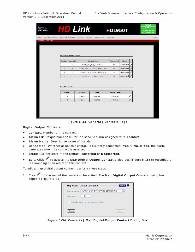
HD Link Installation & Operation Manual 5 – Web Browser Interface Configuration & Operation Version 2.2, December 2011
5-44 Harris Corporation Intraplex Products
Figure 5-33. General | Contacts Page
Digital Output Contacts
● Contact: Number of the contact.
● Alarm ID: Unique numeric ID for the specific alarm assigned to this contact.
● Alarm Name: Descriptive name of the alarm.
● Connected: Whether or not this contact is currently connected: Yes or No. If Yes, the alarm generates when the contact is asserted.
● State: Current state of the contact: Asserted or Deasserted.
● Edit: Click to access the Map Digital Output Contact dialog box (Figure 5-15) to reconfigure the mapping of an alarm to this contact.
To edit a map digital output contact, perform these steps:
1. Click on the row of the contact to be edited. The Map Digital Output Contact dialog box appears (Figure 5-34).
Figure 5-34. Contacts | Map Digital Output Contact Dialog Box
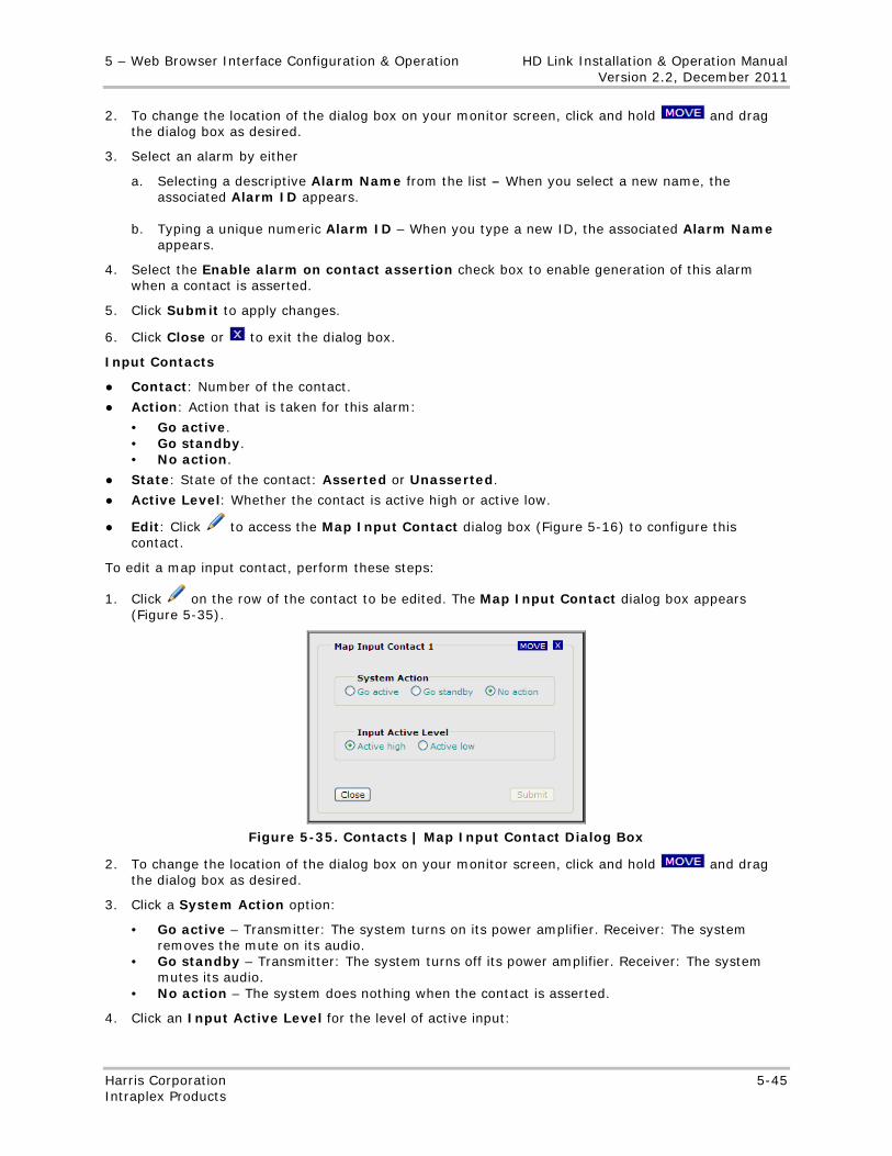
5 – Web Browser Interface Configuration & Operation HD Link Installation & Operation Manual Version 2.2, December 2011
Harris Corporation 5-45 Intraplex Products
2. To change the location of the dialog box on your monitor screen, click and hold and drag the dialog box as desired.
3. Select an alarm by either
a. Selecting a descriptive Alarm Name from the list – When you select a new name, the associated Alarm ID appears.
b. Typing a unique numeric Alarm ID – When you type a new ID, the associated Alarm Name appears.
4. Select the Enable alarm on contact assertion check box to enable generation of this alarm when a contact is asserted.
5. Click Submit to apply changes.
6. Click Close or to exit the dialog box.
Input Contacts
● Contact: Number of the contact.
● Action: Action that is taken for this alarm:
• Go active. • Go standby. • No action.
● State: State of the contact: Asserted or Unasserted.
● Active Level: Whether the contact is active high or active low.
● Edit: Click to access the Map Input Contact dialog box (Figure 5-16) to configure this contact.
To edit a map input contact, perform these steps:
1. Click on the row of the contact to be edited. The Map Input Contact dialog box appears (Figure 5-35).
Figure 5-35. Contacts | Map Input Contact Dialog Box
2. To change the location of the dialog box on your monitor screen, click and hold and drag the dialog box as desired.
3. Click a System Action option:
• Go active – Transmitter: The system turns on its power amplifier. Receiver: The system removes the mute on its audio.
• Go standby – Transmitter: The system turns off its power amplifier. Receiver: The system mutes its audio.
• No action – The system does nothing when the contact is asserted.
4. Click an Input Active Level for the level of active input:
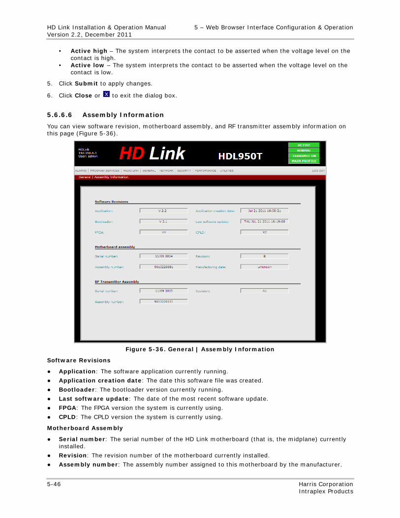
HD Link Installation & Operation Manual 5 – Web Browser Interface Configuration & Operation Version 2.2, December 2011
5-46 Harris Corporation Intraplex Products
• Active high – The system interprets the contact to be asserted when the voltage level on the contact is high.
• Active low – The system interprets the contact to be asserted when the voltage level on the contact is low.
5. Click Submit to apply changes.
6. Click Close or to exit the dialog box.
5.6.6.6 Assembly Information
You can view software revision, motherboard assembly, and RF transmitter assembly information on this page (Figure 5-36).
Figure 5-36. General | Assembly Information
Software Revisions
● Application: The software application currently running.
● Application creation date: The date this software file was created.
● Bootloader: The bootloader version currently running.
● Last software update: The date of the most recent software update.
● FPGA: The FPGA version the system is currently using.
● CPLD: The CPLD version the system is currently using.
Motherboard Assembly
● Serial number: The serial number of the HD Link motherboard (that is, the midplane) currently installed.
● Revision: The revision number of the motherboard currently installed.
● Assembly number: The assembly number assigned to this motherboard by the manufacturer.
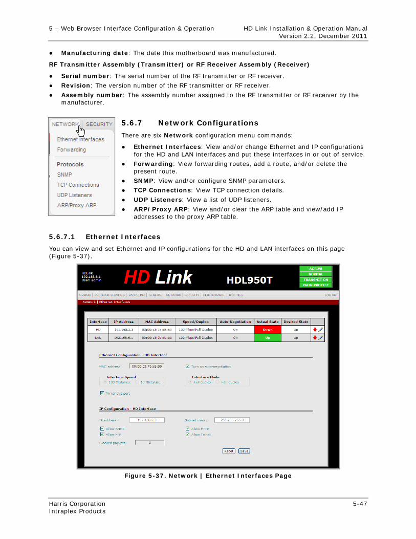
5 – Web Browser Interface Configuration & Operation HD Link Installation & Operation Manual Version 2.2, December 2011
Harris Corporation 5-47 Intraplex Products
● Manufacturing date: The date this motherboard was manufactured.
RF Transmitter Assembly (Transmitter) or RF Receiver Assembly (Receiver)
● Serial number: The serial number of the RF transmitter or RF receiver.
● Revision: The version number of the RF transmitter or RF receiver.
● Assembly number: The assembly number assigned to the RF transmitter or RF receiver by the manufacturer.
5.6.7 Network Configurations
There are six Network configuration menu commands:
● Ethernet Interfaces: View and/or change Ethernet and IP configurations for the HD and LAN interfaces and put these interfaces in or out of service.
● Forwarding: View forwarding routes, add a route, and/or delete the present route.
● SNMP: View and/or configure SNMP parameters.
● TCP Connections: View TCP connection details.
● UDP Listeners: View a list of UDP listeners.
● ARP/Proxy ARP: View and/or clear the ARP table and view/add IP addresses to the proxy ARP table.
5.6.7.1 Ethernet Interfaces
You can view and set Ethernet and IP configurations for the HD and LAN interfaces on this page (Figure 5-37).
Figure 5-37. Network | Ethernet Interfaces Page
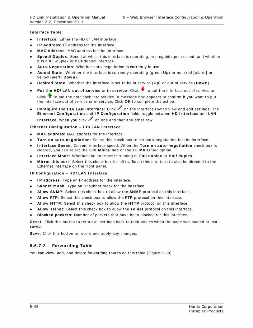
HD Link Installation & Operation Manual 5 – Web Browser Interface Configuration & Operation Version 2.2, December 2011
5-48 Harris Corporation Intraplex Products
Interface Table
● Interface: Either the HD or LAN interface.
● IP Address: IP address for the interface.
● MAC Address: MAC address for the interface.
● Speed/Duplex: Speed at which this interface is operating, in megabits per second, and whether it is a full-duplex or half-duplex interface.
● Auto-Negotiation: Whether auto-negotiation is currently in use.
● Actual State: Whether the interface is currently operating (green Up) or not (red [alarm] or yellow [alert] Down).
● Desired State: Whether the interface is set to be in service (Up) or out of service (Down).
● Put the HD/LAN out of service or in service: Click to put the interface out of service or
Click to put the port back into service. A message box appears to confirm if you want to put the interface out of service or in service. Click OK to complete the action.
● Configure the HD/LAN interface: Click on the interface row to view and edit settings. The Ethernet Configuration and IP Configuration fields toggle between HD Interface and LAN
Interface, when you click on one and then the other row.
Ethernet Configuration – HD/LAN Interface
● MAC address: MAC address for the interface.
● Turn on auto-negotiation: Select this check box to set auto-negotiation for the interface.
● Interface Speed: Current interface speed. When the Turn on auto-negotiation check box is cleared, you can select the 100 Mbits/sec or the 10 Mbits/sec option.
● Interface Mode: Whether the interface is running at Full duplex or Half duplex.
● Mirror this port: Select this check box for all traffic on this interface to also be directed to the Ethernet interface on the front panel.
IP Configuration – HD/LAN Interface
● IP address: Type an IP address for the interface.
● Subnet mask: Type an IP subnet mask for the interface.
● Allow SNMP: Select this check box to allow the SNMP protocol on this interface.
● Allow FTP: Select this check box to allow the FTP protocol on this interface.
● Allow HTTP: Select this check box to allow the HTTP protocol on this interface.
● Allow Telnet: Select this check box to allow the Telnet protocol on this interface.
● Blocked packets: Number of packets that have been blocked for this interface.
Reset: Click this button to return all settings back to their values when the page was loaded or last saved.
Save: Click this button to record and apply any changes.
5.6.7.2 Forwarding Table
You can view, add, and delete forwarding routes on this table (Figure 5-38).
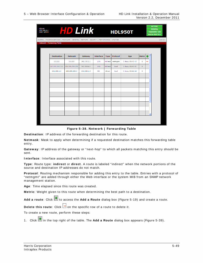
5 – Web Browser Interface Configuration & Operation HD Link Installation & Operation Manual Version 2.2, December 2011
Harris Corporation 5-49 Intraplex Products
Figure 5-38. Network | Forwarding Table
Destination: IP address of the forwarding destination for this route.
Netmask: Mask to apply when determining if a requested destination matches this forwarding table entry.
Gateway: IP address of the gateway or “next-hop” to which all packets matching this entry should be sent.
Interface: Interface associated with this route.
Type: Route type: indirect or direct. A route is labeled “indirect” when the network portions of the source and destination IP addresses do not match.
Protocol: Routing mechanism responsible for adding this entry to the table. Entries with a protocol of “netmgmt” are added through either the Web interface or the system MIB from an SNMP network management station.
Age: Time elapsed since this route was created.
Metric: Weight given to this route when determining the best path to a destination.
Add a route: Click to access the Add a Route dialog box (Figure 5-19) and create a route.
Delete this route: Click on the specific row of a route to delete it.
To create a new route, perform these steps:
1. Click in the top right of the table. The Add a Route dialog box appears (Figure 5-39).
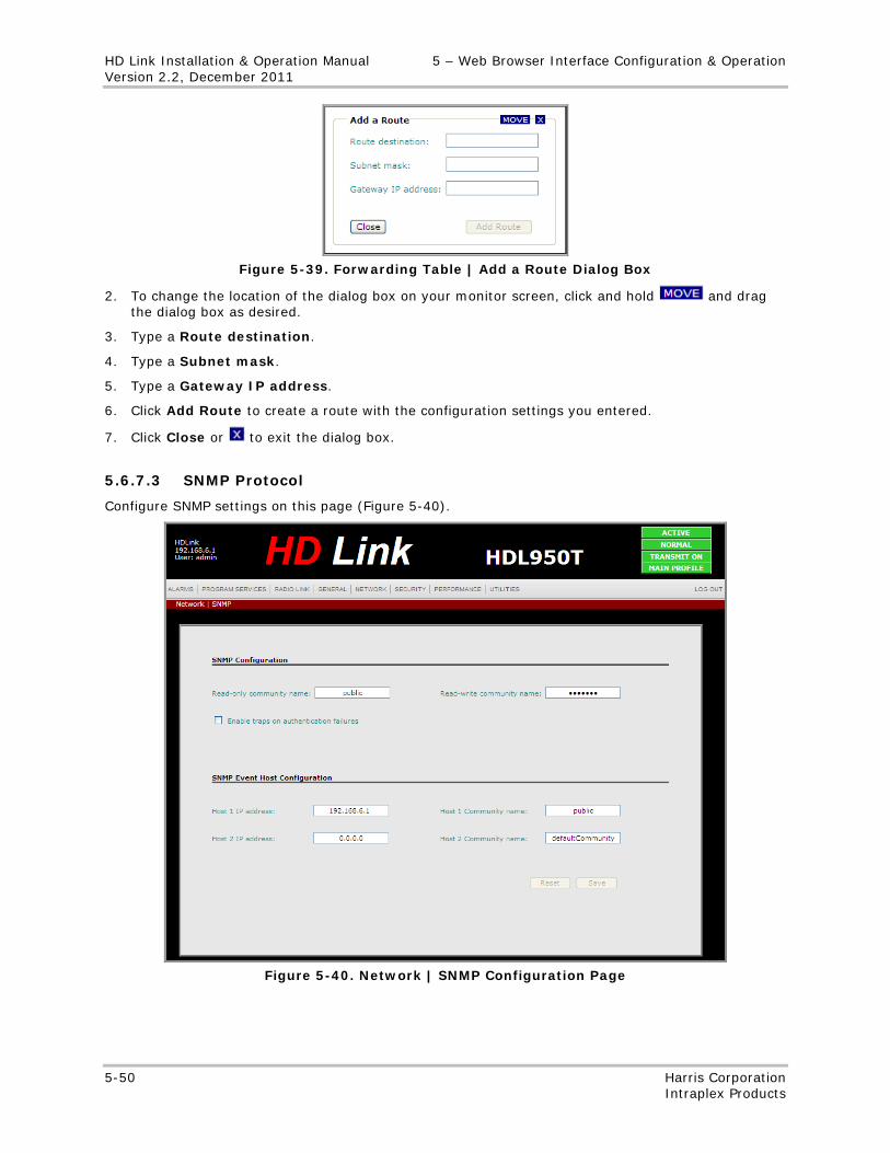
HD Link Installation & Operation Manual 5 – Web Browser Interface Configuration & Operation Version 2.2, December 2011
5-50 Harris Corporation Intraplex Products
Figure 5-39. Forwarding Table | Add a Route Dialog Box
2. To change the location of the dialog box on your monitor screen, click and hold and drag the dialog box as desired.
3. Type a Route destination.
4. Type a Subnet mask.
5. Type a Gateway IP address.
6. Click Add Route to create a route with the configuration settings you entered.
7. Click Close or to exit the dialog box.
5.6.7.3 SNMP Protocol
Configure SNMP settings on this page (Figure 5-40).
Figure 5-40. Network | SNMP Configuration Page
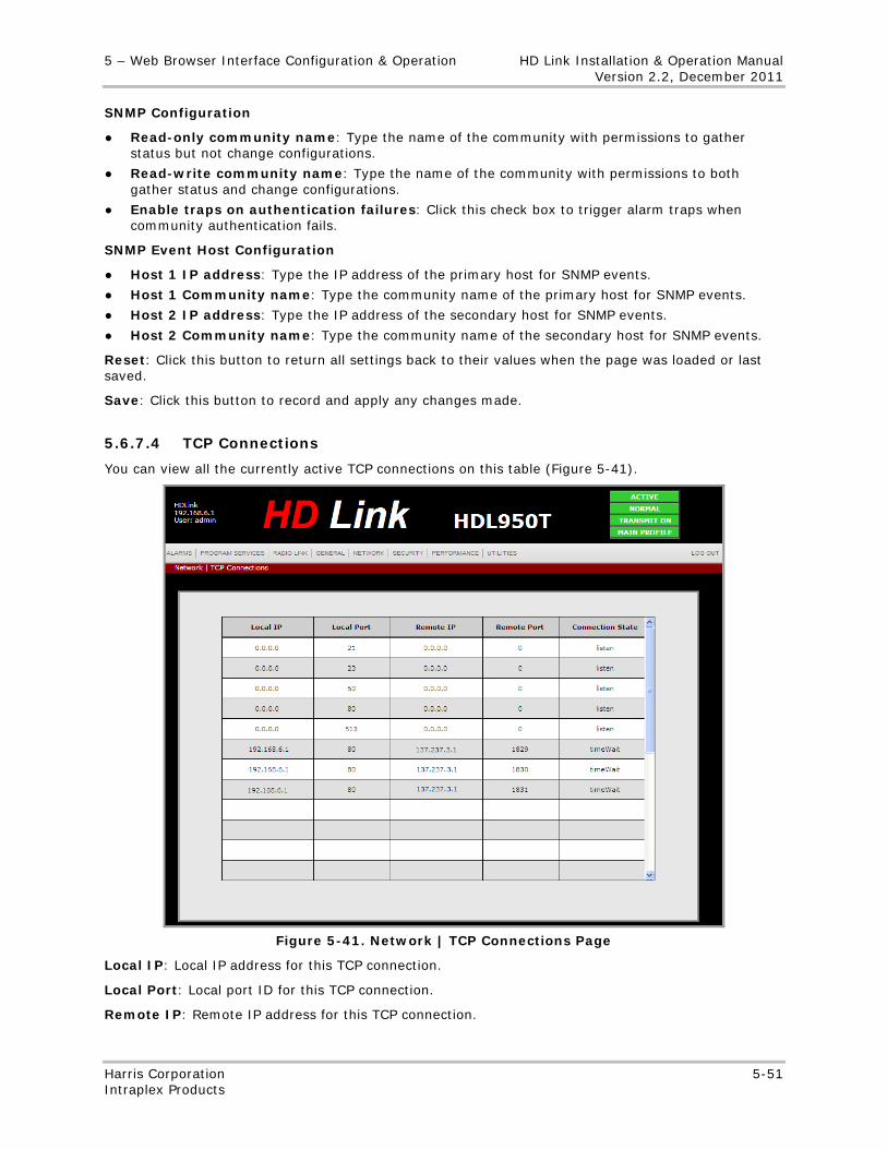
5 – Web Browser Interface Configuration & Operation HD Link Installation & Operation Manual Version 2.2, December 2011
Harris Corporation 5-51 Intraplex Products
SNMP Configuration
● Read-only community name: Type the name of the community with permissions to gather status but not change configurations.
● Read-write community name: Type the name of the community with permissions to both gather status and change configurations.
● Enable traps on authentication failures: Click this check box to trigger alarm traps when community authentication fails.
SNMP Event Host Configuration
● Host 1 IP address: Type the IP address of the primary host for SNMP events.
● Host 1 Community name: Type the community name of the primary host for SNMP events.
● Host 2 IP address: Type the IP address of the secondary host for SNMP events.
● Host 2 Community name: Type the community name of the secondary host for SNMP events.
Reset: Click this button to return all settings back to their values when the page was loaded or last saved.
Save: Click this button to record and apply any changes made.
5.6.7.4 TCP Connections
You can view all the currently active TCP connections on this table (Figure 5-41).
Figure 5-41. Network | TCP Connections Page
Local IP: Local IP address for this TCP connection.
Local Port: Local port ID for this TCP connection.
Remote IP: Remote IP address for this TCP connection.
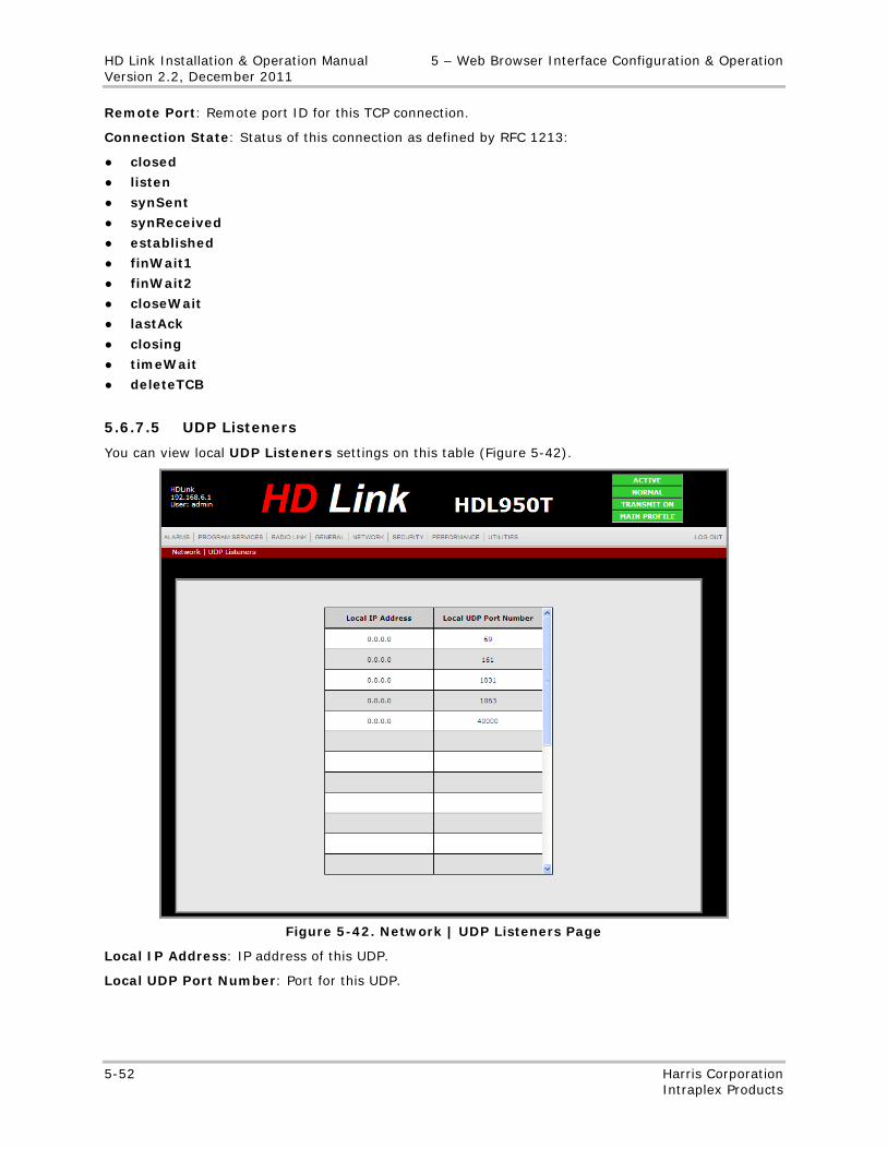
HD Link Installation & Operation Manual 5 – Web Browser Interface Configuration & Operation Version 2.2, December 2011
5-52 Harris Corporation Intraplex Products
Remote Port: Remote port ID for this TCP connection.
Connection State: Status of this connection as defined by RFC 1213:
● closed
● listen
● synSent
● synReceived
● established
● finWait1
● finWait2
● closeWait
● lastAck
● closing
● timeWait
● deleteTCB
5.6.7.5 UDP Listeners
You can view local UDP Listeners settings on this table (Figure 5-42).
Figure 5-42. Network | UDP Listeners Page
Local IP Address: IP address of this UDP.
Local UDP Port Number: Port for this UDP.
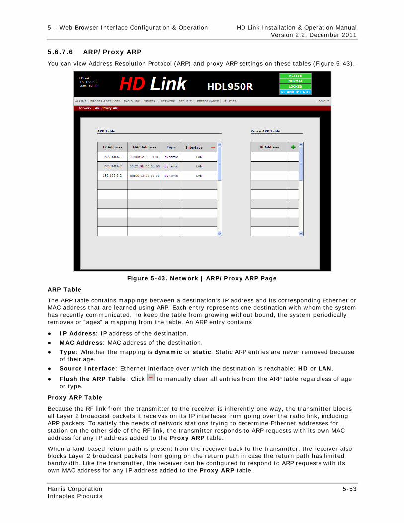
5 – Web Browser Interface Configuration & Operation HD Link Installation & Operation Manual Version 2.2, December 2011
Harris Corporation 5-53 Intraplex Products
5.6.7.6 ARP/Proxy ARP
You can view Address Resolution Protocol (ARP) and proxy ARP settings on these tables (Figure 5-43).
Figure 5-43. Network | ARP/Proxy ARP Page
ARP Table
The ARP table contains mappings between a destination’s IP address and its corresponding Ethernet or MAC address that are learned using ARP. Each entry represents one destination with whom the system has recently communicated. To keep the table from growing without bound, the system periodically removes or “ages” a mapping from the table. An ARP entry contains
● IP Address: IP address of the destination.
● MAC Address: MAC address of the destination.
● Type: Whether the mapping is dynamic or static. Static ARP entries are never removed because of their age.
● Source Interface: Ethernet interface over which the destination is reachable: HD or LAN.
● Flush the ARP Table: Click to manually clear all entries from the ARP table regardless of age or type.
Proxy ARP Table
Because the RF link from the transmitter to the receiver is inherently one way, the transmitter blocks all Layer 2 broadcast packets it receives on its IP interfaces from going over the radio link, including ARP packets. To satisfy the needs of network stations trying to determine Ethernet addresses for station on the other side of the RF link, the transmitter responds to ARP requests with its own MAC address for any IP address added to the Proxy ARP table.
When a land-based return path is present from the receiver back to the transmitter, the receiver also blocks Layer 2 broadcast packets from going on the return path in case the return path has limited bandwidth. Like the transmitter, the receiver can be configured to respond to ARP requests with its own MAC address for any IP address added to the Proxy ARP table.
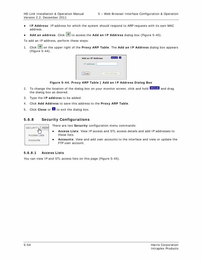
HD Link Installation & Operation Manual 5 – Web Browser Interface Configuration & Operation Version 2.2, December 2011
5-54 Harris Corporation Intraplex Products
● IP Address: IP address for which the system should respond to ARP requests with its own MAC address.
● Add an address: Click to access the Add an IP Address dialog box (Figure 5-40).
To add an IP address, perform these steps:
1. Click on the upper right of the Proxy ARP Table. The Add an IP Address dialog box appears (Figure 5-44).
Figure 5-44. Proxy ARP Table | Add an IP Address Dialog Box
2. To change the location of the dialog box on your monitor screen, click and hold and drag the dialog box as desired.
3. Type the IP address to be added.
4. Click Add Address to save this address to the Proxy ARP Table.
5. Click Close or to exit the dialog box.
5.6.8 Security Configurations
There are two Security configuration menu commands:
● Access Lists: View IP access and STL access details and add IP addresses to these lists.
● Accounts: View and add user accounts to the interface and view or update the FTP user account.
5.6.8.1 Access Lists
You can view IP and STL access lists on this page (Figure 5-45).
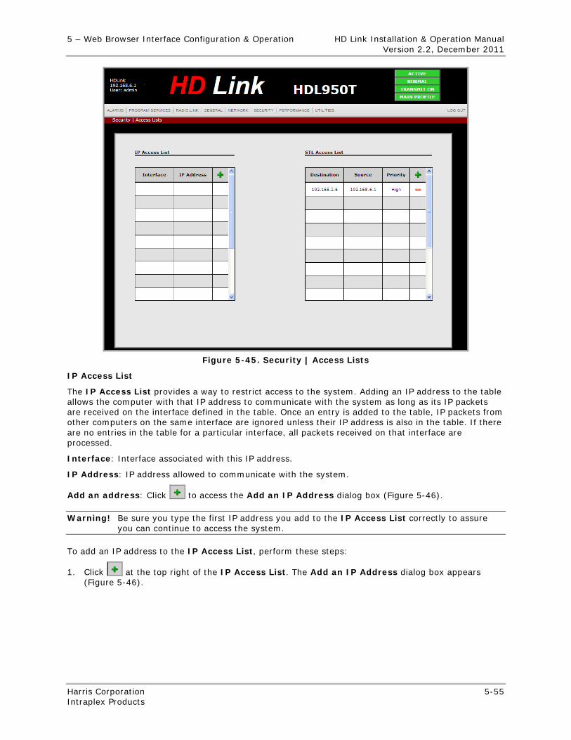
5 – Web Browser Interface Configuration & Operation HD Link Installation & Operation Manual Version 2.2, December 2011
Harris Corporation 5-55 Intraplex Products
Figure 5-45. Security | Access Lists
IP Access List
The IP Access List provides a way to restrict access to the system. Adding an IP address to the table allows the computer with that IP address to communicate with the system as long as its IP packets are received on the interface defined in the table. Once an entry is added to the table, IP packets from other computers on the same interface are ignored unless their IP address is also in the table. If there are no entries in the table for a particular interface, all packets received on that interface are processed.
Interface: Interface associated with this IP address.
IP Address: IP address allowed to communicate with the system.
Add an address: Click to access the Add an IP Address dialog box (Figure 5-46).
Warning! Be sure you type the first IP address you add to the IP Access List correctly to assure you can continue to access the system.
To add an IP address to the IP Access List, perform these steps:
1. Click at the top right of the IP Access List. The Add an IP Address dialog box appears (Figure 5-46).
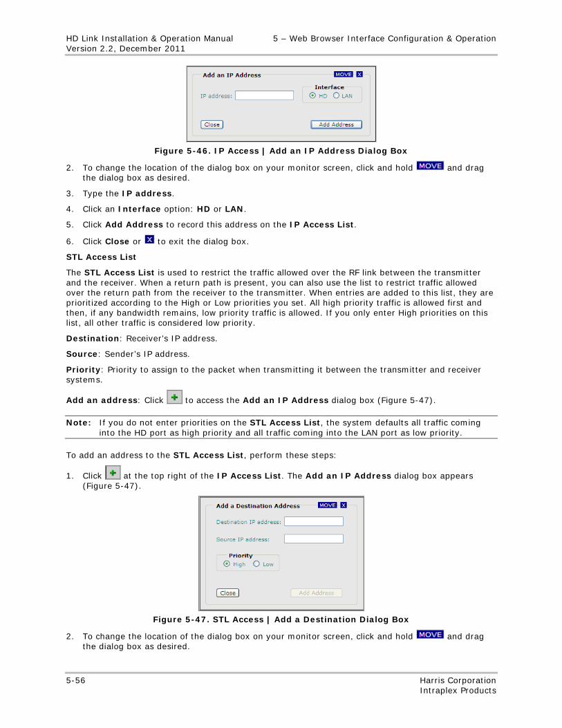
HD Link Installation & Operation Manual 5 – Web Browser Interface Configuration & Operation Version 2.2, December 2011
5-56 Harris Corporation Intraplex Products
Figure 5-46. IP Access | Add an IP Address Dialog Box
2. To change the location of the dialog box on your monitor screen, click and hold and drag the dialog box as desired.
3. Type the IP address.
4. Click an Interface option: HD or LAN.
5. Click Add Address to record this address on the IP Access List.
6. Click Close or to exit the dialog box.
STL Access List
The STL Access List is used to restrict the traffic allowed over the RF link between the transmitter and the receiver. When a return path is present, you can also use the list to restrict traffic allowed over the return path from the receiver to the transmitter. When entries are added to this list, they are prioritized according to the High or Low priorities you set. All high priority traffic is allowed first and then, if any bandwidth remains, low priority traffic is allowed. If you only enter High priorities on this list, all other traffic is considered low priority.
Destination: Receiver’s IP address.
Source: Sender’s IP address.
Priority: Priority to assign to the packet when transmitting it between the transmitter and receiver systems.
Add an address: Click to access the Add an IP Address dialog box (Figure 5-47).
Note: If you do not enter priorities on the STL Access List, the system defaults all traffic coming into the HD port as high priority and all traffic coming into the LAN port as low priority.
To add an address to the STL Access List, perform these steps:
1. Click at the top right of the IP Access List. The Add an IP Address dialog box appears (Figure 5-47).
Figure 5-47. STL Access | Add a Destination Dialog Box
2. To change the location of the dialog box on your monitor screen, click and hold and drag the dialog box as desired.
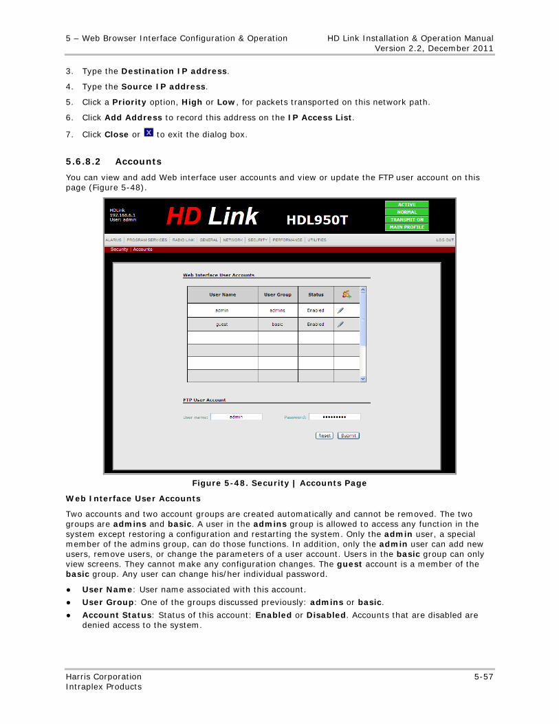
5 – Web Browser Interface Configuration & Operation HD Link Installation & Operation Manual Version 2.2, December 2011
Harris Corporation 5-57 Intraplex Products
3. Type the Destination IP address.
4. Type the Source IP address.
5. Click a Priority option, High or Low, for packets transported on this network path.
6. Click Add Address to record this address on the IP Access List.
7. Click Close or to exit the dialog box.
5.6.8.2 Accounts
You can view and add Web interface user accounts and view or update the FTP user account on this page (Figure 5-48).
Figure 5-48. Security | Accounts Page
Web Interface User Accounts
Two accounts and two account groups are created automatically and cannot be removed. The two groups are admins and basic. A user in the admins group is allowed to access any function in the system except restoring a configuration and restarting the system. Only the admin user, a special member of the admins group, can do those functions. In addition, only the admin user can add new users, remove users, or change the parameters of a user account. Users in the basic group can only view screens. They cannot make any configuration changes. The guest account is a member of the basic group. Any user can change his/her individual password.
● User Name: User name associated with this account.
● User Group: One of the groups discussed previously: admins or basic.
● Account Status: Status of this account: Enabled or Disabled. Accounts that are disabled are denied access to the system.
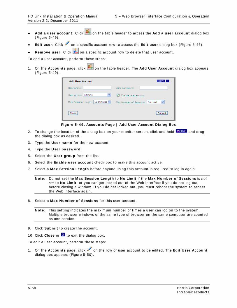
HD Link Installation & Operation Manual 5 – Web Browser Interface Configuration & Operation Version 2.2, December 2011
5-58 Harris Corporation Intraplex Products
● Add a user account: Click on the table header to access the Add a user account dialog box (Figure 5-49).
● Edit user: Click on a specific account row to access the Edit user dialog box (Figure 5-46).
● Remove user: Click on a specific account row to delete that user account.
To add a user account, perform these steps:
1. On the Accounts page, click on the table header. The Add User Account dialog box appears (Figure 5-49).
Figure 5-49. Accounts Page | Add User Account Dialog Box
2. To change the location of the dialog box on your monitor screen, click and hold and drag the dialog box as desired.
3. Type the User name for the new account.
4. Type the User password.
5. Select the User group from the list.
6. Select the Enable user account check box to make this account active.
7. Select a Max Session Length before anyone using this account is required to log in again.
Note: Do not set the Max Session Length to No Limit if the Max Number of Sessions is not set to No Limit, or you can get locked out of the Web interface if you do not log out before closing a window. If you do get locked out, you must reboot the system to access the Web interface again.
8. Select a Max Number of Sessions for this user account.
Note: This setting indicates the maximum number of times a user can log on to the system. Multiple browser windows of the same type of browser on the same computer are counted as one session.
9. Click Submit to create the account.
10. Click Close or to exit the dialog box.
To edit a user account, perform these steps:
1. On the Accounts page, click on the row of user account to be edited. The Edit User Account dialog box appears (Figure 5-50).
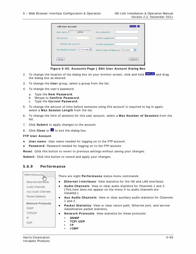
5 – Web Browser Interface Configuration & Operation HD Link Installation & Operation Manual Version 2.2, December 2011
Harris Corporation 5-59 Intraplex Products
Figure 5-50. Accounts Page | Edit User Account Dialog Box
2. To change the location of the dialog box on your monitor screen, click and hold and drag the dialog box as desired.
3. To change the User group, select a group from the list.
4. To change the user’s password
a. Type the New Password. b. Retype to Confirm Password. c. Type the Current Password.
5. To change the amount of time before someone using this account is required to log in again, select a Max Session Length from the list.
6. To change the limit of sessions for this user account, select a Max Number of Sessions from the list.
7. Click Submit to apply changes to the account.
8. Click Close or to exit the dialog box.
FTP User Account
● User name: User name needed for logging on to the FTP account.
● Password: Password needed for logging on to the FTP account.
Reset: Click this button to revert to previous settings without saving your changes.
Submit: Click this button to record and apply your changes.
5.6.9 Performance
There are eight Performance status menu commands:
● Ethernet Interfaces: View statistics for the HD and LAN interfaces.
● Audio Channels: View or clear audio statistics for Channels 1 and 2. (This item does not appear on the menu if no audio channels are installed.)
● Aux Audio Channels: View or clear auxiliary audio statistics for Channels 1 and 2.
● Packet Statistics: View or clear return path, Ethernet port, and service classification packet statistics.
● Network Protocols: View statistics for these protocols:
• SNMP • TCP/UDP • IP • ICMP
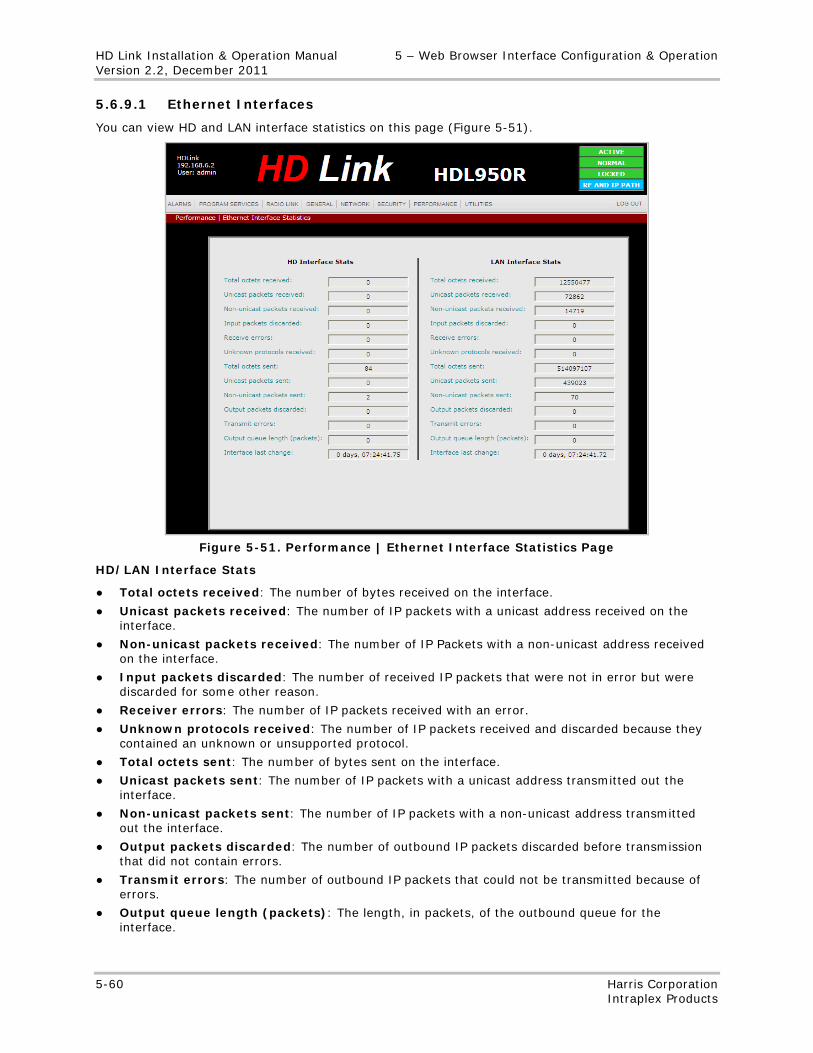
HD Link Installation & Operation Manual 5 – Web Browser Interface Configuration & Operation Version 2.2, December 2011
5-60 Harris Corporation Intraplex Products
5.6.9.1 Ethernet Interfaces
You can view HD and LAN interface statistics on this page (Figure 5-51).
Figure 5-51. Performance | Ethernet Interface Statistics Page
HD/LAN Interface Stats
● Total octets received: The number of bytes received on the interface.
● Unicast packets received: The number of IP packets with a unicast address received on the interface.
● Non-unicast packets received: The number of IP Packets with a non-unicast address received on the interface.
● Input packets discarded: The number of received IP packets that were not in error but were discarded for some other reason.
● Receiver errors: The number of IP packets received with an error.
● Unknown protocols received: The number of IP packets received and discarded because they contained an unknown or unsupported protocol.
● Total octets sent: The number of bytes sent on the interface.
● Unicast packets sent: The number of IP packets with a unicast address transmitted out the interface.
● Non-unicast packets sent: The number of IP packets with a non-unicast address transmitted out the interface.
● Output packets discarded: The number of outbound IP packets discarded before transmission that did not contain errors.
● Transmit errors: The number of outbound IP packets that could not be transmitted because of errors.
● Output queue length (packets): The length, in packets, of the outbound queue for the interface.
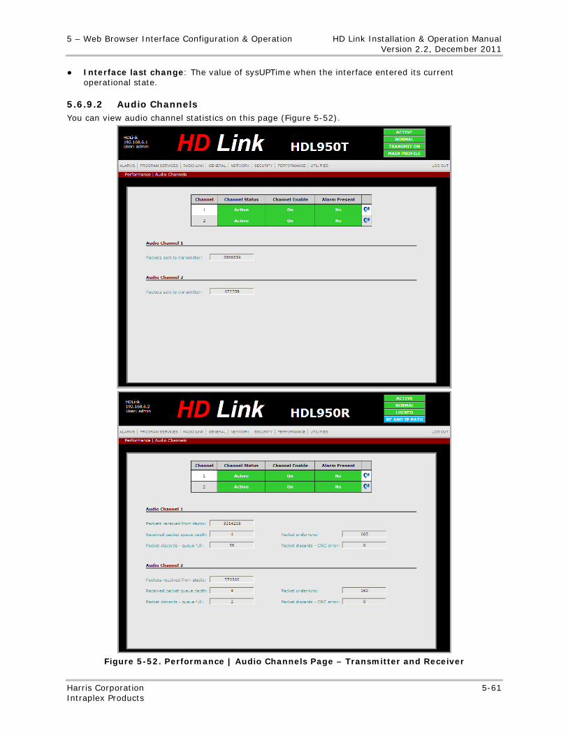
5 – Web Browser Interface Configuration & Operation HD Link Installation & Operation Manual Version 2.2, December 2011
Harris Corporation 5-61 Intraplex Products
● Interface last change: The value of sysUPTime when the interface entered its current operational state.
5.6.9.2 Audio Channels You can view audio channel statistics on this page (Figure 5-52).
Figure 5-52. Performance | Audio Channels Page – Transmitter and Receiver
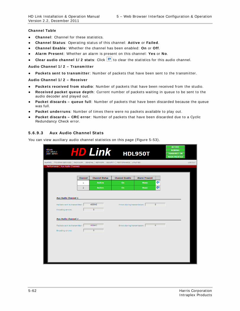
HD Link Installation & Operation Manual 5 – Web Browser Interface Configuration & Operation Version 2.2, December 2011
5-62 Harris Corporation Intraplex Products
Channel Table
● Channel: Channel for these statistics.
● Channel Status: Operating status of this channel: Active or Failed.
● Channel Enable: Whether the channel has been enabled: On or Off.
● Alarm Present: Whether an alarm is present on this channel: Yes or No.
● Clear audio channel 1/2 stats: Click to clear the statistics for this audio channel.
Audio Channel 1/2 – Transmitter
● Packets sent to transmitter: Number of packets that have been sent to the transmitter.
Audio Channel 1/2 – Receiver
● Packets received from studio: Number of packets that have been received from the studio.
● Received packet queue depth: Current number of packets waiting in queue to be sent to the audio decoder and played out.
● Packet discards – queue full: Number of packets that have been discarded because the queue was full.
● Packet underruns: Number of times there were no packets available to play out.
● Packet discards – CRC error: Number of packets that have been discarded due to a Cyclic Redundancy Check error.
5.6.9.3 Aux Audio Channel Stats
You can view auxiliary audio channel statistics on this page (Figure 5-53).
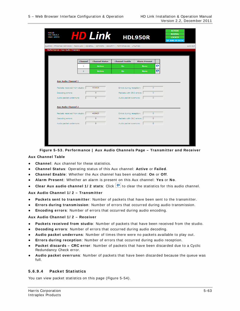
5 – Web Browser Interface Configuration & Operation HD Link Installation & Operation Manual Version 2.2, December 2011
Harris Corporation 5-63 Intraplex Products
Figure 5-53. Performance | Aux Audio Channels Page – Transmitter and Receiver
Aux Channel Table
● Channel: Aux channel for these statistics.
● Channel Status: Operating status of this Aux channel: Active or Failed.
● Channel Enable: Whether the Aux channel has been enabled: On or Off.
● Alarm Present: Whether an alarm is present on this Aux channel: Yes or No.
● Clear Aux audio channel 1/2 stats: Click to clear the statistics for this audio channel.
Aux Audio Channel 1/2 – Transmitter
● Packets sent to transmitter: Number of packets that have been sent to the transmitter.
● Errors during transmission: Number of errors that occurred during audio transmission.
● Encoding errors: Number of errors that occurred during audio encoding.
Aux Audio Channel 1/2 – Receiver
● Packets received from studio: Number of packets that have been received from the studio.
● Decoding errors: Number of errors that occurred during audio decoding.
● Audio packet underruns: Number of times there were no packets available to play out.
● Errors during reception: Number of errors that occurred during audio reception.
● Packet discards – CRC error: Number of packets that have been discarded due to a Cyclic Redundancy Check error.
● Audio packet overruns: Number of packets that have been discarded because the queue was full.
5.6.9.4 Packet Statistics
You can view packet statistics on this page (Figure 5-54).
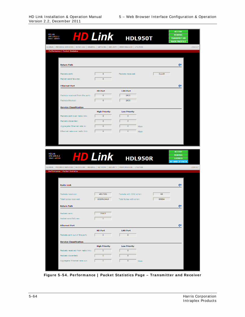
HD Link Installation & Operation Manual 5 – Web Browser Interface Configuration & Operation Version 2.2, December 2011
5-64 Harris Corporation Intraplex Products
Figure 5-54. Performance | Packet Statistics Page – Transmitter and Receiver
5 – Web Browser Interface Configuration & Operation HD Link Installation & Operation Manual Version 2.2, December 2011
Harris Corporation 5-65 Intraplex Products
Radio Link – Receiver
● Packets received: The total number of packets received over the radio link.
● Packets with CRC error: The total number of packets received with CRC error indication over the radio link.
● Total bytes received: The total number of bytes received over the radio link.
● Total bytes with error: The number of bytes received with a packet level CRC indication.
● Reset the radio link statistics: Click to clear the statistics recorded for the radio link.
Return Path
● Packets sent: The total number of packets sent over the return path.
● Packets received (transmitter only): The total number of packets received on the transmitter from the receiver over the return path.
● Packet send failures: The total number of packets attempted to be sent that failed.
● Reset the return path statistics: Click to clear the statistics recorded for the return path.
Ethernet Port
● Packets received from the port (transmitter only): The total number of packets the transmitter received from the HD Port and from the LAN Port.
● Packets blocked (transmitter only): The total number of packets that were not received on the HD Port and from the LAN Port because they were blocked.
● Packets sent out of the port (receiver only): The total number of packets sent out from the HD Port and from the LAN Port.
● Reset the forward path statistics: Click to clear the statistics recorded for the forward path.
Service Classification
● Packets sent over radio link (transmitter only): The total number of packets that have been sent over the radio link, both High and Low Priority.
● Aggregate Ethernet rate in (transmitter only): The rate the data travels to the HD Link system, in kbps.
● Ethernet rate over radio link (transmitter only): The rate the data travels over the radio link, in kbps.
● Packets received from radio link (receiver only): The rate the data travels from the radio link, in kbps.
● Packets discarded: The total number of packets that were discarded.
● Aggregate Ethernet rate out (receiver only): The rate the data travels from the HD Link system, in kbps.
5.6.9.5 SNMP Statistics
You can view SNMP receive and send statistics on this page (Figure 5-55).
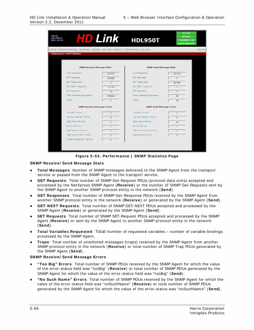
HD Link Installation & Operation Manual 5 – Web Browser Interface Configuration & Operation Version 2.2, December 2011
5-66 Harris Corporation Intraplex Products
Figure 5-55. Performance | SNMP Statistics Page
SNMP Receive/Send Message Stats
● Total Messages: Number of SNMP messages delivered to the SNMP Agent from the transport service or passed from the SNMP Agent to the transport service.
● GET Requests: Total number of SNMP Get-Request PDUs (protocol data units) accepted and processed by the NetXpress SNMP Agent (Receive) or the number of SNMP Get-Requests sent by the SNMP Agent to another SNMP protocol entity in the network (Send).
● GET Responses: Total number of SNMP Get-Response PDUs received by the SNMP Agent from another SNMP protocol entity in the network (Receive) or generated by the SNMP Agent (Send).
● GET-NEXT Requests: Total number of SNMP GET-NEXT PDUs accepted and processed by the SNMP Agent (Receive) or generated by the SNMP Agent (Send).
● SET Requests: Total number of SNMP SET-Request PDUs accepted and processed by the SNMP Agent (Receive) or sent by the SNMP Agent to another SNMP protocol entity in the network (Send).
● Total Variables Requested: Total number of requested variables – number of variable bindings processed by the SNMP Agent.
● Traps: Total number of unsolicited messages (traps) received by the SNMP Agent from another SNMP protocol entity in the network (Receive) or total number of SNMP Trap PDUs generated by the SNMP Agent (Send).
SNMP Receive/Send Message Errors
● “Too Big” Errors: Total number of SNMP PDUs received by the SNMP Agent for which the value of the error-status field was “tooBig” (Receive) or total number of SNMP PDUs generated by the SNMP Agent for which the value of the error-status field was “tooBig” (Send).
● “No Such Name” Errors: Total number of SNMP PDUs received by the SNMP Agent for which the value of the error-status field was “noSuchName” (Receive) or total number of SNMP PDUs generated by the SNMP Agent for which the value of the error-status was “noSuchName” (Send).
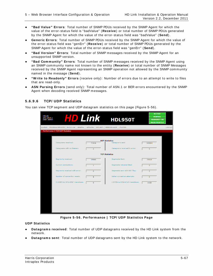
5 – Web Browser Interface Configuration & Operation HD Link Installation & Operation Manual Version 2.2, December 2011
Harris Corporation 5-67 Intraplex Products
● “Bad Value” Errors: Total number of SNMP PDUs received by the SNMP Agent for which the value of the error-status field is “badValue” (Receive) or total number of SNMP PDUs generated by the SNMP Agent for which the value of the error-status field was “badValue” (Send).
● Generic Errors: Total number of SNMP PDUs received by the SNMP Agent for which the value of the error-status field was “genErr” (Receive) or total number of SNMP PDUs generated by the SNMP Agent for which the value of the error-status field was “genErr” (Send).
● “Bad Version” Errors: Total number of SNMP messages received by the SNMP Agent for an unsupported SNMP version.
● “Bad Community” Errors: Total number of SNMP messages received by the SNMP Agent using an SNMP community name not known to the entity (Receive) or total number of SNMP Messages received by the SNMP Agent representing an SNMP operation not allowed by the SNMP community named in the message (Send).
● “Write to Readonly” Errors (receive only): Number of errors due to an attempt to write to files that are read-only.
● ASN Parsing Errors (send only): Total number of ASN.1 or BER errors encountered by the SNMP Agent when decoding received SNMP messages.
5.6.9.6 TCP/UDP Statistics
You can view TCP segment and UDP datagram statistics on this page (Figure 5-56).
Figure 5-56. Performance | TCP/UDP Statistics Page
UDP Statistics
● Datagrams received: Total number of UDP datagrams received by the HD Link system from the network.
● Datagrams sent: Total number of UDP datagrams sent by the HD Link system to the network.
HD Link Installation & Operation Manual 5 – Web Browser Interface Configuration & Operation Version 2.2, December 2011
5-68 Harris Corporation Intraplex Products
● Datagrams with no listener: Total number of UDP datagrams received for which no application in the HD Link system was listening to the destination port.
● Datagrams received in error: Total number of UDP datagrams received by the HD Link system that could not be delivered for reasons other than the lack of an application at the destination port.
TCP Statistics
● Segments received: Total number of TCP segments received, including those received in error.
● Segments sent: Total number of TCP segments sent, including those on current connections.
● Current connections: Total number of current TCP connections.
● Segments retransmitted: Total number of TCP segments transmitted by the HD Link system that contain one or more previously transmitted octets.
● Segments received with error: Total number of TCP segments received by the HD Link system that were determined to have ICMP-specific errors (such as bad TCP checksums).
● Segments sent with RST flag: Total number of TCP segments sent by the HD Link system containing the RST (reset) flag.
● Number of connection resets: Total number established connections reset.
● Failed connection attempts: Total number of times TCP connections have made a direction transition to the CLOSED state from either SYN-SENT state or SYN-RCVD state, plus the number of times TCP connections have made a direct transition to the LISTEN state from the SYN-RCVD state.
● CLOSED to SYN-SENT transitions: Total number of times TCP connections have made a direct transition to the SYN-SENT state from the CLOSED state.
● LISTEN to SYN-RCVD transitions: Total number of times TCP connections have made a direct transition to the SYN_RCVD state from the LISTEN state.
5.6.9.7 IP Statistics
You can view IP datagram and fragmentation statistics on this page (Figure 5-57).
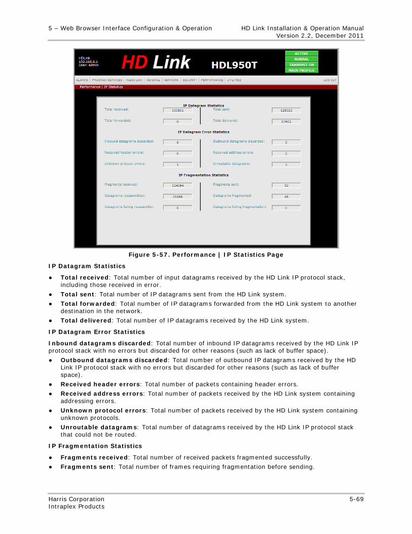
5 – Web Browser Interface Configuration & Operation HD Link Installation & Operation Manual Version 2.2, December 2011
Harris Corporation 5-69 Intraplex Products
Figure 5-57. Performance | IP Statistics Page
IP Datagram Statistics
● Total received: Total number of input datagrams received by the HD Link IP protocol stack, including those received in error.
● Total sent: Total number of IP datagrams sent from the HD Link system.
● Total forwarded: Total number of IP datagrams forwarded from the HD Link system to another destination in the network.
● Total delivered: Total number of IP datagrams received by the HD Link system.
IP Datagram Error Statistics
Inbound datagrams discarded: Total number of inbound IP datagrams received by the HD Link IP protocol stack with no errors but discarded for other reasons (such as lack of buffer space).
● Outbound datagrams discarded: Total number of outbound IP datagrams received by the HD Link IP protocol stack with no errors but discarded for other reasons (such as lack of buffer space).
● Received header errors: Total number of packets containing header errors.
● Received address errors: Total number of packets received by the HD Link system containing addressing errors.
● Unknown protocol errors: Total number of packets received by the HD Link system containing unknown protocols.
● Unroutable datagrams: Total number of datagrams received by the HD Link IP protocol stack that could not be routed.
IP Fragmentation Statistics
● Fragments received: Total number of received packets fragmented successfully.
● Fragments sent: Total number of frames requiring fragmentation before sending.
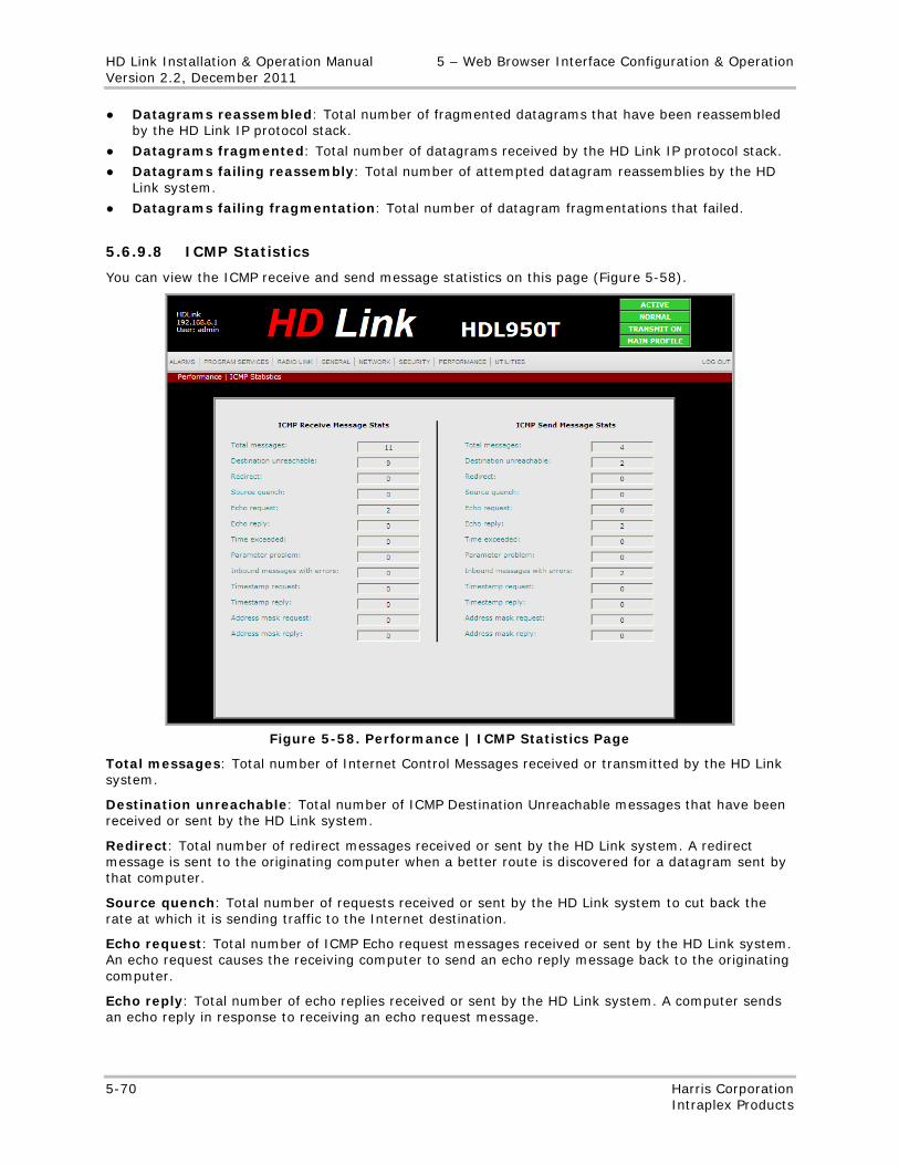
HD Link Installation & Operation Manual 5 – Web Browser Interface Configuration & Operation Version 2.2, December 2011
5-70 Harris Corporation Intraplex Products
● Datagrams reassembled: Total number of fragmented datagrams that have been reassembled by the HD Link IP protocol stack.
● Datagrams fragmented: Total number of datagrams received by the HD Link IP protocol stack.
● Datagrams failing reassembly: Total number of attempted datagram reassemblies by the HD Link system.
● Datagrams failing fragmentation: Total number of datagram fragmentations that failed.
5.6.9.8 ICMP Statistics
You can view the ICMP receive and send message statistics on this page (Figure 5-58).
Figure 5-58. Performance | ICMP Statistics Page
Total messages: Total number of Internet Control Messages received or transmitted by the HD Link system.
Destination unreachable: Total number of ICMP Destination Unreachable messages that have been received or sent by the HD Link system.
Redirect: Total number of redirect messages received or sent by the HD Link system. A redirect message is sent to the originating computer when a better route is discovered for a datagram sent by that computer.
Source quench: Total number of requests received or sent by the HD Link system to cut back the rate at which it is sending traffic to the Internet destination.
Echo request: Total number of ICMP Echo request messages received or sent by the HD Link system. An echo request causes the receiving computer to send an echo reply message back to the originating computer.
Echo reply: Total number of echo replies received or sent by the HD Link system. A computer sends an echo reply in response to receiving an echo request message.
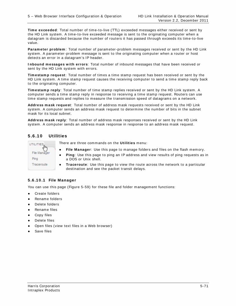
5 – Web Browser Interface Configuration & Operation HD Link Installation & Operation Manual Version 2.2, December 2011
Harris Corporation 5-71 Intraplex Products
Time exceeded: Total number of time-to-live (TTL) exceeded messages either received or sent by the HD Link system. A time-to-live exceeded message is sent to the originating computer when a datagram is discarded because the number of routers it has passed through exceeds its time-to-live value.
Parameter problem: Total number of parameter-problem messages received or sent by the HD Link system. A parameter-problem message is sent to the originating computer when a router or host detects an error in a datagram's IP header.
Inbound messages with errors: Total number of inbound messages that have been received or sent by the HD Link system with errors.
Timestamp request: Total number of times a time stamp request has been received or sent by the HD Link system. A time stamp request causes the receiving computer to send a time stamp reply back to the originating computer.
Timestamp reply: Total number of time stamp replies received or sent by the HD Link system. A computer sends a time stamp reply in response to receiving a time stamp request. Routers can use time stamp requests and replies to measure the transmission speed of datagrams on a network.
Address mask request: Total number of address mask requests received or sent by the HD Link system. A computer sends an address mask request to determine the number of bits in the subnet mask for its local subnet.
Address mask reply: Total number of address mask responses received or sent by the HD Link system. A computer sends an address mask response in response to an address mask request.
5.6.10 Utilities
There are three commands on the Utilities menu:
● File Manager: Use this page to manage folders and files on the flash memory.
● Ping: Use this page to ping an IP address and view results of ping requests as in a DOS or Unix shell.
● Traceroute: Use this page to view the route across the network to a particular destination and see the packet transit delays.
5.6.10.1 File Manager
You can use this page (Figure 5-59) for these file and folder management functions:
● Create folders
● Rename folders
● Delete folders
● Rename files
● Copy files
● Delete files
● Open files (view text files in a Web browser)
● Save files
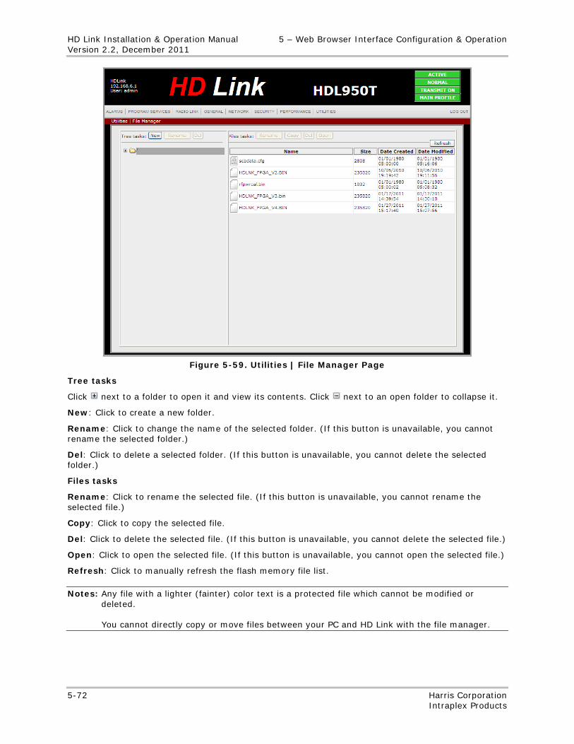
HD Link Installation & Operation Manual 5 – Web Browser Interface Configuration & Operation Version 2.2, December 2011
5-72 Harris Corporation Intraplex Products
Figure 5-59. Utilities | File Manager Page
Tree tasks
Click next to a folder to open it and view its contents. Click next to an open folder to collapse it.
New: Click to create a new folder.
Rename: Click to change the name of the selected folder. (If this button is unavailable, you cannot rename the selected folder.)
Del: Click to delete a selected folder. (If this button is unavailable, you cannot delete the selected folder.)
Files tasks
Rename: Click to rename the selected file. (If this button is unavailable, you cannot rename the selected file.)
Copy: Click to copy the selected file.
Del: Click to delete the selected file. (If this button is unavailable, you cannot delete the selected file.)
Open: Click to open the selected file. (If this button is unavailable, you cannot open the selected file.)
Refresh: Click to manually refresh the flash memory file list.
Notes: Any file with a lighter (fainter) color text is a protected file which cannot be modified or deleted. You cannot directly copy or move files between your PC and HD Link with the file manager.
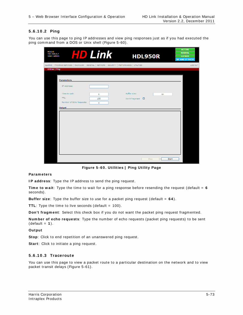
5 – Web Browser Interface Configuration & Operation HD Link Installation & Operation Manual Version 2.2, December 2011
Harris Corporation 5-73 Intraplex Products
5.6.10.2 Ping
You can use this page to ping IP addresses and view ping responses just as if you had executed the ping command from a DOS or Unix shell (Figure 5-60).
Figure 5-60. Utilities | Ping Utility Page
Parameters
IP address: Type the IP address to send the ping request.
Time to wait: Type the time to wait for a ping response before resending the request (default = 6 seconds).
Buffer size: Type the buffer size to use for a packet ping request (default = 64).
TTL: Type the time to live seconds (default = 100).
Don’t fragment: Select this check box if you do not want the packet ping request fragmented.
Number of echo requests: Type the number of echo requests (packet ping requests) to be sent (default = 1).
Output
Stop: Click to end repetition of an unanswered ping request.
Start: Click to initiate a ping request.
5.6.10.3 Traceroute
You can use this page to view a packet route to a particular destination on the network and to view packet transit delays (Figure 5-61).
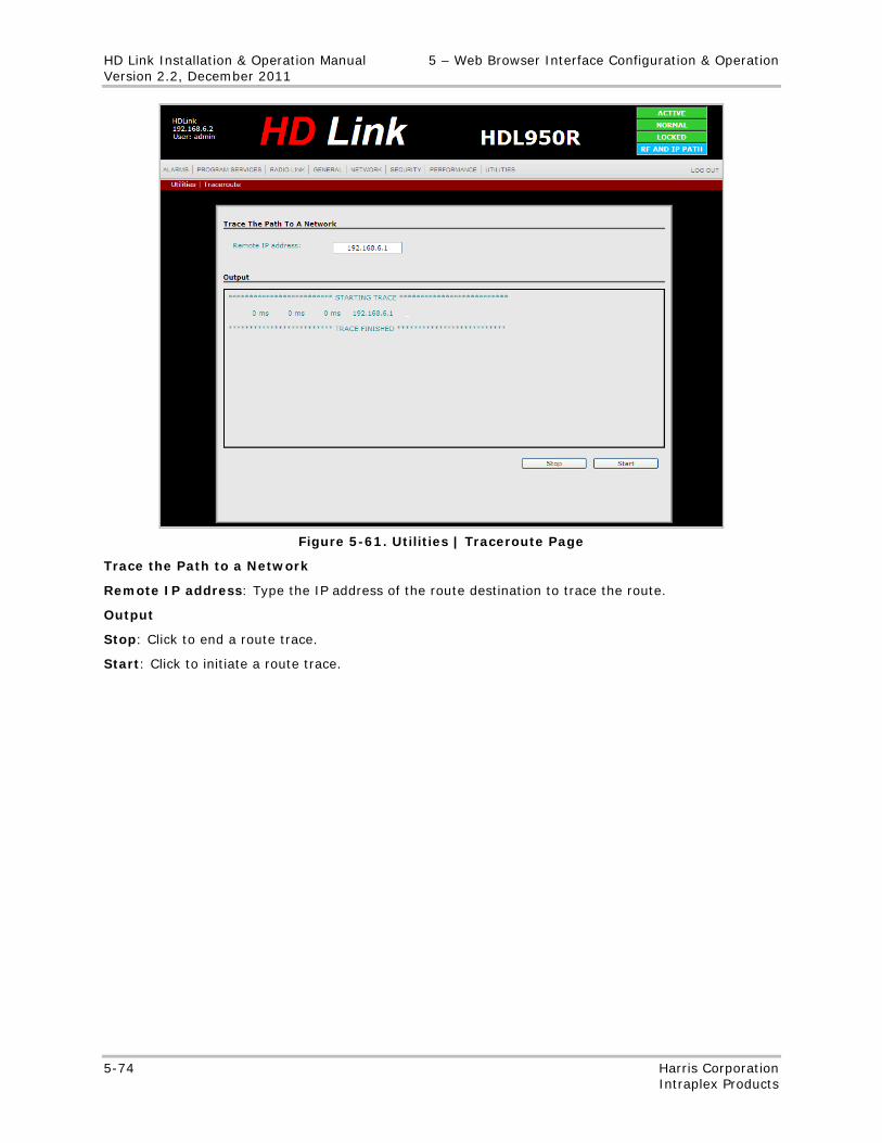
HD Link Installation & Operation Manual 5 – Web Browser Interface Configuration & Operation Version 2.2, December 2011
5-74 Harris Corporation Intraplex Products
Figure 5-61. Utilities | Traceroute Page
Trace the Path to a Network
Remote IP address: Type the IP address of the route destination to trace the route.
Output
Stop: Click to end a route trace.
Start: Click to initiate a route trace.
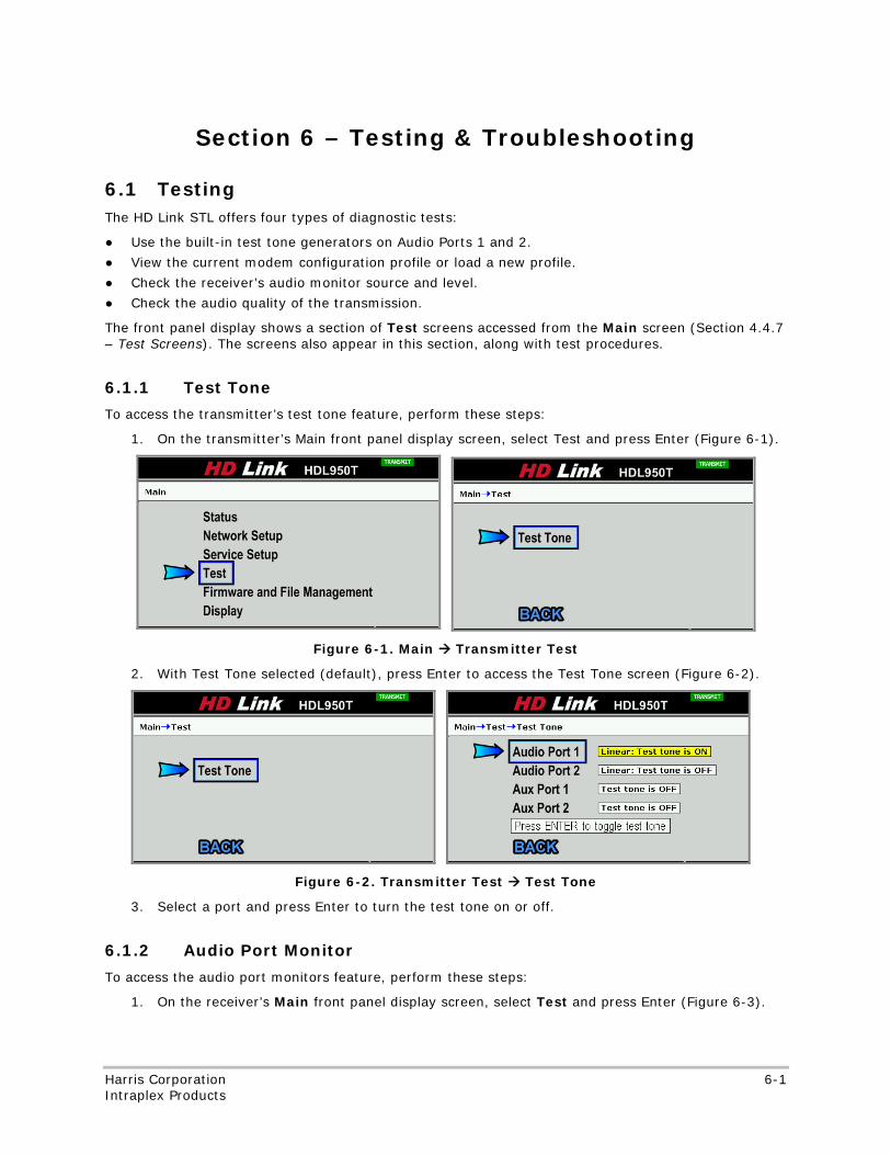
No header here
Harris Corporation 6-1 Intraplex Products
Section 6 – Testing & Troubleshooting
6.1 Testing The HD Link STL offers four types of diagnostic tests:
● Use the built-in test tone generators on Audio Ports 1 and 2.
● View the current modem configuration profile or load a new profile.
● Check the receiver’s audio monitor source and level.
● Check the audio quality of the transmission.
The front panel display shows a section of Test screens accessed from the Main screen (Section 4.4.7 – Test Screens). The screens also appear in this section, along with test procedures.
6.1.1 Test Tone
To access the transmitter’s test tone feature, perform these steps:
1. On the transmitter’s Main front panel display screen, select Test and press Enter (Figure 6-1).
Figure 6-1. Main Transmitter Test
2. With Test Tone selected (default), press Enter to access the Test Tone screen (Figure 6-2).
Figure 6-2. Transmitter Test Test Tone
3. Select a port and press Enter to turn the test tone on or off.
6.1.2 Audio Port Monitor
To access the audio port monitors feature, perform these steps:
1. On the receiver’s Main front panel display screen, select Test and press Enter (Figure 6-3).
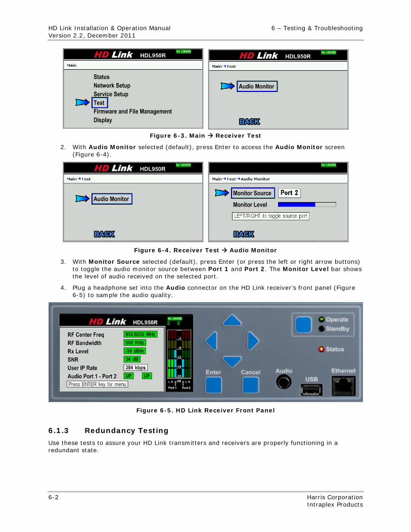
HD Link Installation & Operation Manual 6 – Testing & Troubleshooting Version 2.2, December 2011
6-2 Harris Corporation Intraplex Products
Figure 6-3. Main Receiver Test
2. With Audio Monitor selected (default), press Enter to access the Audio Monitor screen (Figure 6-4).
Figure 6-4. Receiver Test Audio Monitor
3. With Monitor Source selected (default), press Enter (or press the left or right arrow buttons) to toggle the audio monitor source between Port 1 and Port 2. The Monitor Level bar shows the level of audio received on the selected port.
4. Plug a headphone set into the Audio connector on the HD Link receiver’s front panel (Figure 6-5) to sample the audio quality.
Figure 6-5. HD Link Receiver Front Panel
6.1.3 Redundancy Testing
Use these tests to assure your HD Link transmitters and receivers are properly functioning in a redundant state.
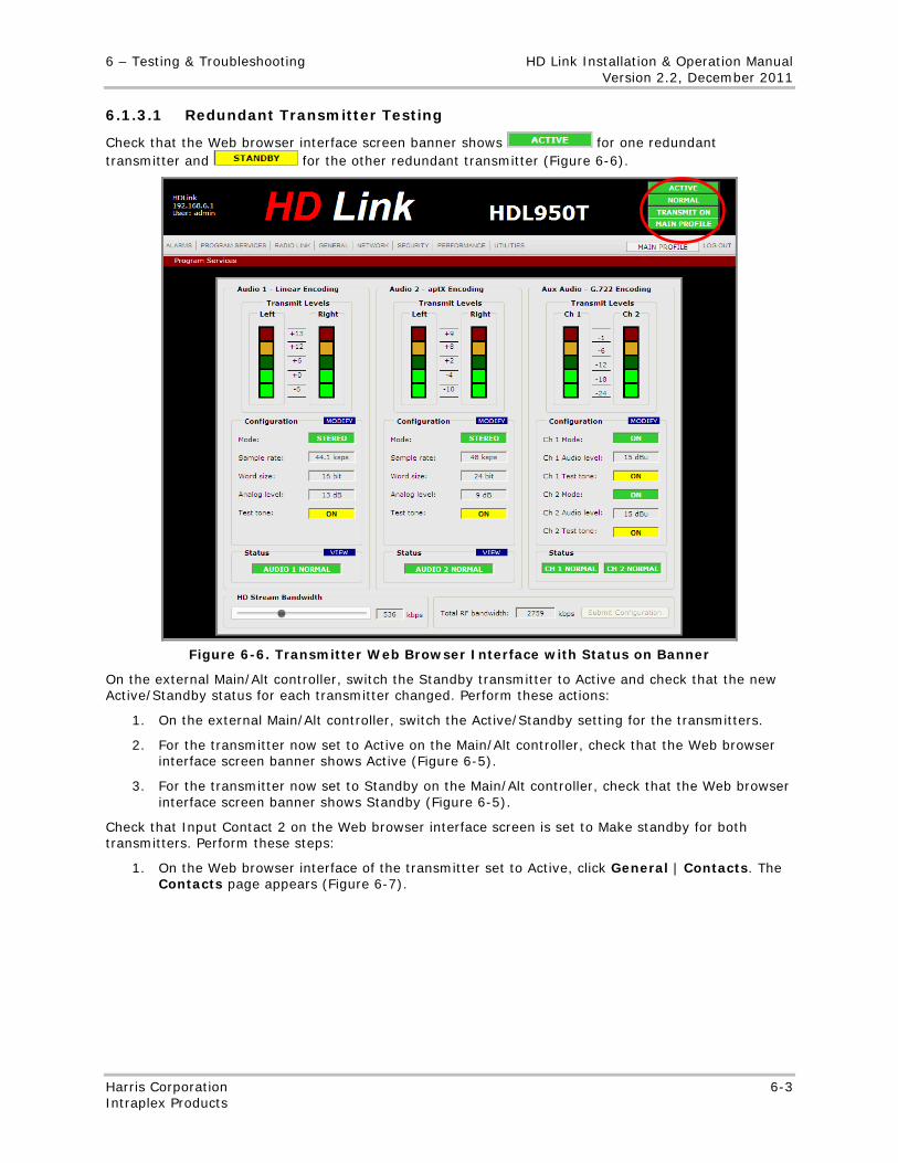
6 – Testing & Troubleshooting HD Link Installation & Operation Manual Version 2.2, December 2011
Harris Corporation 6-3 Intraplex Products
6.1.3.1 Redundant Transmitter Testing
Check that the Web browser interface screen banner shows for one redundant transmitter and for the other redundant transmitter (Figure 6-6).
Figure 6-6. Transmitter Web Browser Interface with Status on Banner
On the external Main/Alt controller, switch the Standby transmitter to Active and check that the new Active/Standby status for each transmitter changed. Perform these actions:
1. On the external Main/Alt controller, switch the Active/Standby setting for the transmitters.
2. For the transmitter now set to Active on the Main/Alt controller, check that the Web browser interface screen banner shows Active (Figure 6-5).
3. For the transmitter now set to Standby on the Main/Alt controller, check that the Web browser interface screen banner shows Standby (Figure 6-5).
Check that Input Contact 2 on the Web browser interface screen is set to Make standby for both transmitters. Perform these steps:
1. On the Web browser interface of the transmitter set to Active, click General | Contacts. The Contacts page appears (Figure 6-7).
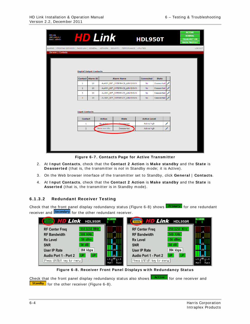
HD Link Installation & Operation Manual 6 – Testing & Troubleshooting Version 2.2, December 2011
6-4 Harris Corporation Intraplex Products
Figure 6-7. Contacts Page for Active Transmitter
2. At Input Contacts, check that the Contact 2 Action is Make standby and the State is Deasserted (that is, the transmitter is not in Standby mode; it is Active).
3. On the Web browser interface of the transmitter set to Standby, click General | Contacts.
4. At Input Contacts, check that the Contact 2 Action is Make standby and the State is Asserted (that is, the transmitter is in Standby mode).
6.1.3.2 Redundant Receiver Testing
Check that the front panel display redundancy status (Figure 6-8) shows for one redundant
receiver and for the other redundant receiver.
Figure 6-8. Receiver Front Panel Displays with Redundancy Status
Check that the front panel display redundancy status also shows for one receiver and
for the other receiver (Figure 6-8).
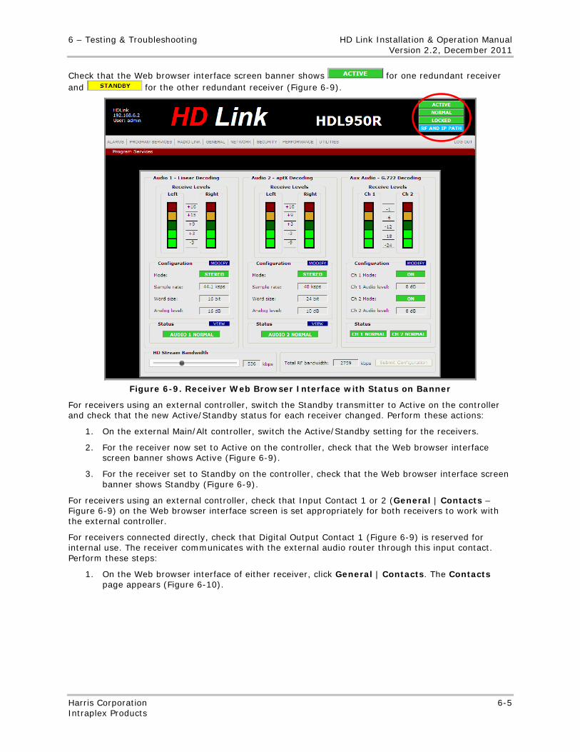
6 – Testing & Troubleshooting HD Link Installation & Operation Manual Version 2.2, December 2011
Harris Corporation 6-5 Intraplex Products
Check that the Web browser interface screen banner shows for one redundant receiver and for the other redundant receiver (Figure 6-9).
Figure 6-9. Receiver Web Browser Interface with Status on Banner
For receivers using an external controller, switch the Standby transmitter to Active on the controller and check that the new Active/Standby status for each receiver changed. Perform these actions:
1. On the external Main/Alt controller, switch the Active/Standby setting for the receivers.
2. For the receiver now set to Active on the controller, check that the Web browser interface screen banner shows Active (Figure 6-9).
3. For the receiver set to Standby on the controller, check that the Web browser interface screen banner shows Standby (Figure 6-9).
For receivers using an external controller, check that Input Contact 1 or 2 (General | Contacts – Figure 6-9) on the Web browser interface screen is set appropriately for both receivers to work with the external controller.
For receivers connected directly, check that Digital Output Contact 1 (Figure 6-9) is reserved for internal use. The receiver communicates with the external audio router through this input contact. Perform these steps:
1. On the Web browser interface of either receiver, click General | Contacts. The Contacts page appears (Figure 6-10).
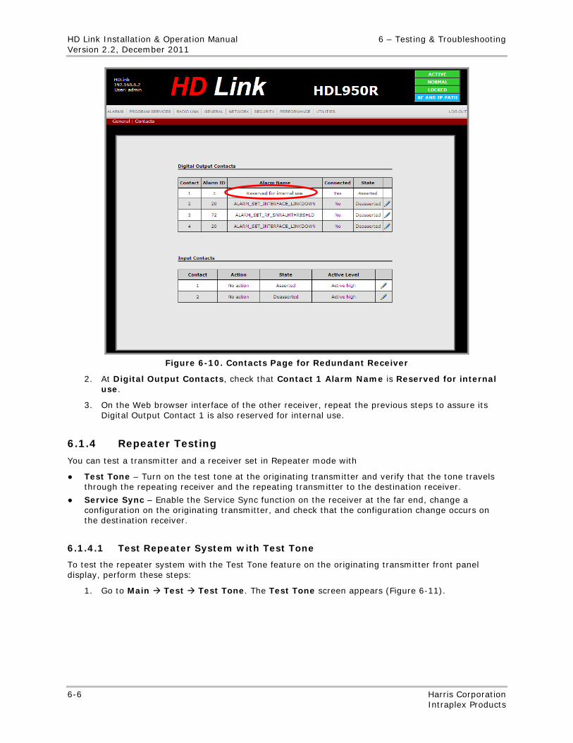
HD Link Installation & Operation Manual 6 – Testing & Troubleshooting Version 2.2, December 2011
6-6 Harris Corporation Intraplex Products
Figure 6-10. Contacts Page for Redundant Receiver
2. At Digital Output Contacts, check that Contact 1 Alarm Name is Reserved for internal use.
3. On the Web browser interface of the other receiver, repeat the previous steps to assure its Digital Output Contact 1 is also reserved for internal use.
6.1.4 Repeater Testing
You can test a transmitter and a receiver set in Repeater mode with
● Test Tone – Turn on the test tone at the originating transmitter and verify that the tone travels through the repeating receiver and the repeating transmitter to the destination receiver.
● Service Sync – Enable the Service Sync function on the receiver at the far end, change a configuration on the originating transmitter, and check that the configuration change occurs on the destination receiver.
6.1.4.1 Test Repeater System with Test Tone
To test the repeater system with the Test Tone feature on the originating transmitter front panel display, perform these steps:
1. Go to Main Test Test Tone. The Test Tone screen appears (Figure 6-11).
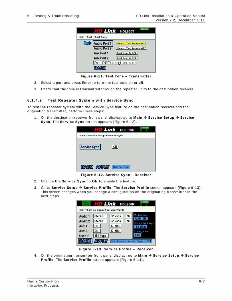
6 – Testing & Troubleshooting HD Link Installation & Operation Manual Version 2.2, December 2011
Harris Corporation 6-7 Intraplex Products
Figure 6-11. Test Tone – Transmitter
2. Select a port and press Enter to turn the test tone on or off.
3. Check that the tone is transmitted through the repeater units to the destination receiver.
6.1.4.2 Test Repeater System with Service Sync
To test the repeater system with the Service Sync feature on the destination receiver and the originating transmitter, perform these steps:
1. On the destination receiver front panel display, go to Main Service Setup Service Sync. The Service Sync screen appears (Figure 6-12).
Figure 6-12. Service Sync – Receiver
2. Change the Service Sync to ON to enable the feature.
3. Go to Service Setup Service Profile. The Service Profile screen appears (Figure 6-13). This screen changes when you change a configuration on the originating transmitter in the next steps.
Figure 6-13. Service Profile – Receiver
4. On the originating transmitter front panel display, go to Main Service Setup Service Profile. The Service Profile screen appears (Figure 6-14).
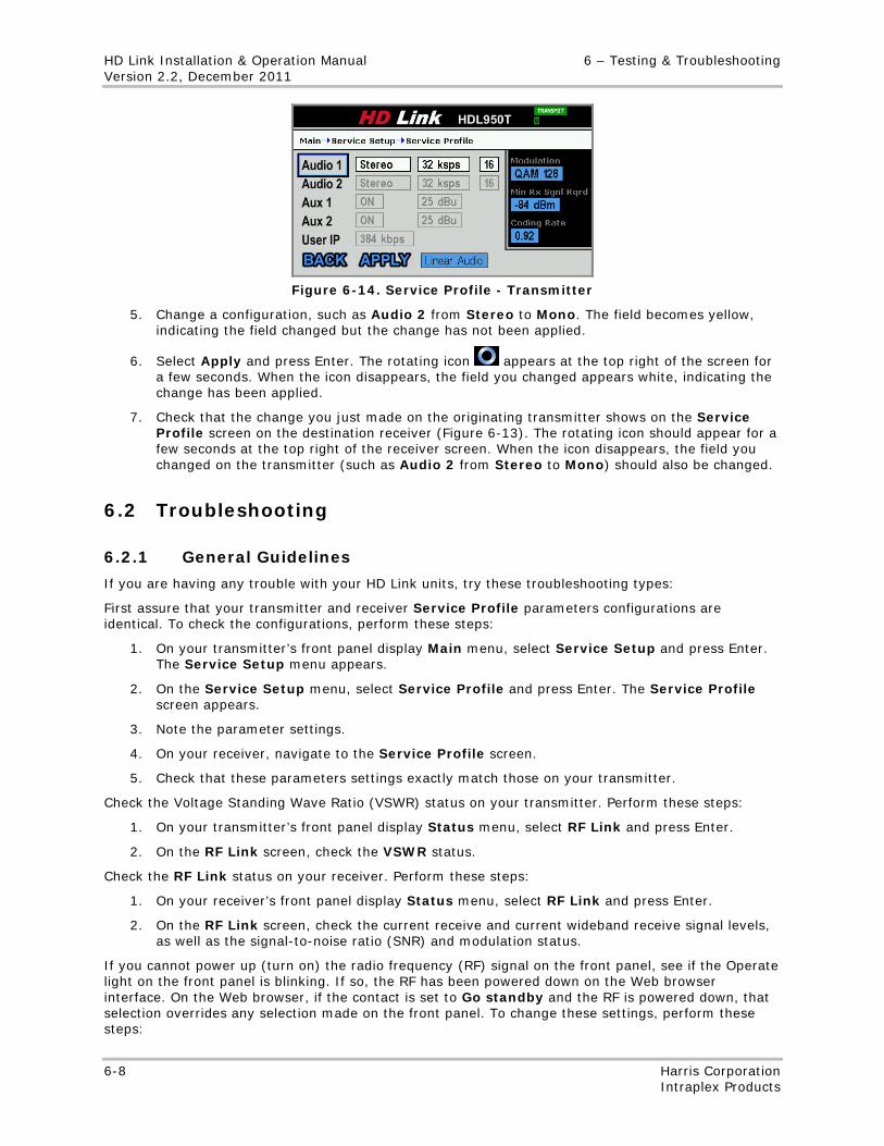
HD Link Installation & Operation Manual 6 – Testing & Troubleshooting Version 2.2, December 2011
6-8 Harris Corporation Intraplex Products
Figure 6-14. Service Profile - Transmitter
5. Change a configuration, such as Audio 2 from Stereo to Mono. The field becomes yellow, indicating the field changed but the change has not been applied.
6. Select Apply and press Enter. The rotating icon appears at the top right of the screen for a few seconds. When the icon disappears, the field you changed appears white, indicating the change has been applied.
7. Check that the change you just made on the originating transmitter shows on the Service Profile screen on the destination receiver (Figure 6-13). The rotating icon should appear for a few seconds at the top right of the receiver screen. When the icon disappears, the field you changed on the transmitter (such as Audio 2 from Stereo to Mono) should also be changed.
6.2 Troubleshooting
6.2.1 General Guidelines
If you are having any trouble with your HD Link units, try these troubleshooting types:
First assure that your transmitter and receiver Service Profile parameters configurations are identical. To check the configurations, perform these steps:
1. On your transmitter’s front panel display Main menu, select Service Setup and press Enter. The Service Setup menu appears.
2. On the Service Setup menu, select Service Profile and press Enter. The Service Profile screen appears.
3. Note the parameter settings.
4. On your receiver, navigate to the Service Profile screen.
5. Check that these parameters settings exactly match those on your transmitter.
Check the Voltage Standing Wave Ratio (VSWR) status on your transmitter. Perform these steps:
1. On your transmitter’s front panel display Status menu, select RF Link and press Enter.
2. On the RF Link screen, check the VSWR status.
Check the RF Link status on your receiver. Perform these steps:
1. On your receiver’s front panel display Status menu, select RF Link and press Enter.
2. On the RF Link screen, check the current receive and current wideband receive signal levels, as well as the signal-to-noise ratio (SNR) and modulation status.
If you cannot power up (turn on) the radio frequency (RF) signal on the front panel, see if the Operate light on the front panel is blinking. If so, the RF has been powered down on the Web browser interface. On the Web browser, if the contact is set to Go standby and the RF is powered down, that selection overrides any selection made on the front panel. To change these settings, perform these steps:
6 – Testing & Troubleshooting HD Link Installation & Operation Manual Version 2.2, December 2011
Harris Corporation 6-9 Intraplex Products
1. On the Web browser interface, go to General | Contacts.
2. At Input Contacts, click the Edit input contact for the contact with an Action of Go Standby.
3. On the Map Input Contact 1 dialog box, click No action for a System Action.
4. Click Submit.
5. Go to Radio Link.
6. Click the On button to power up (turn on) the RF signal.
6.2.2 Redundancy Guidelines
If you have any trouble with redundant HD Link units, check these configuration settings:
Check that your transmitters have the same HD port IP address and a Standalone redundancy role. Perform these steps:
1. On the System Setup menu of one transmitter’s front panel display, select Network Setup and press Enter. The Network Setup menu appears.
2. On the Network Setup menu, with HD Port selected, press Enter. The HD Port screen appears.
3. On the HD Port screen, make note of the IP Address.
4. Press Cancel twice to return to the System Setup menu.
5. On the System Setup menu, select Redundancy Setup and press Enter. The Redundancy Setup menu appears.
6. Check that the Redundancy Role is Standalone.
7. Repeat the previous steps on the other transmitter to assure it has the same HD Port IP address and also has a Standalone redundancy role.
Check that your receivers have the same HD port IP address and either a Standalone redundancy role (if using an external controller) or Primary/Secondary redundancy (if the receivers are connected directly). Perform these steps:
1. On the System Setup menu of one receiver, select Network Setup and press Enter. The Network Setup menu appears.
2. On the Network Setup menu, with HD Port selected, press Enter. The HD Port screen appears.
3. On the HD Port screen, make note of the IP Address.
4. Press Cancel twice to return to the System Setup menu.
5. Select Redundancy Setup and press Enter. The Redundancy Setup menu appears.
6. Check that the Redundancy Role is Standalone (if using an external controller) or Primary or Secondary (if the receivers are connected directly).
7. On the other receiver, use the previous steps to check that it has the same the HD Port IP address and that the Redundancy Role is Standalone (if using an external controller) or Primary/Secondary (if the receivers are connected directly). If you have connected the receivers directly, one receiver should have a Primary role and the other should have a Secondary role.
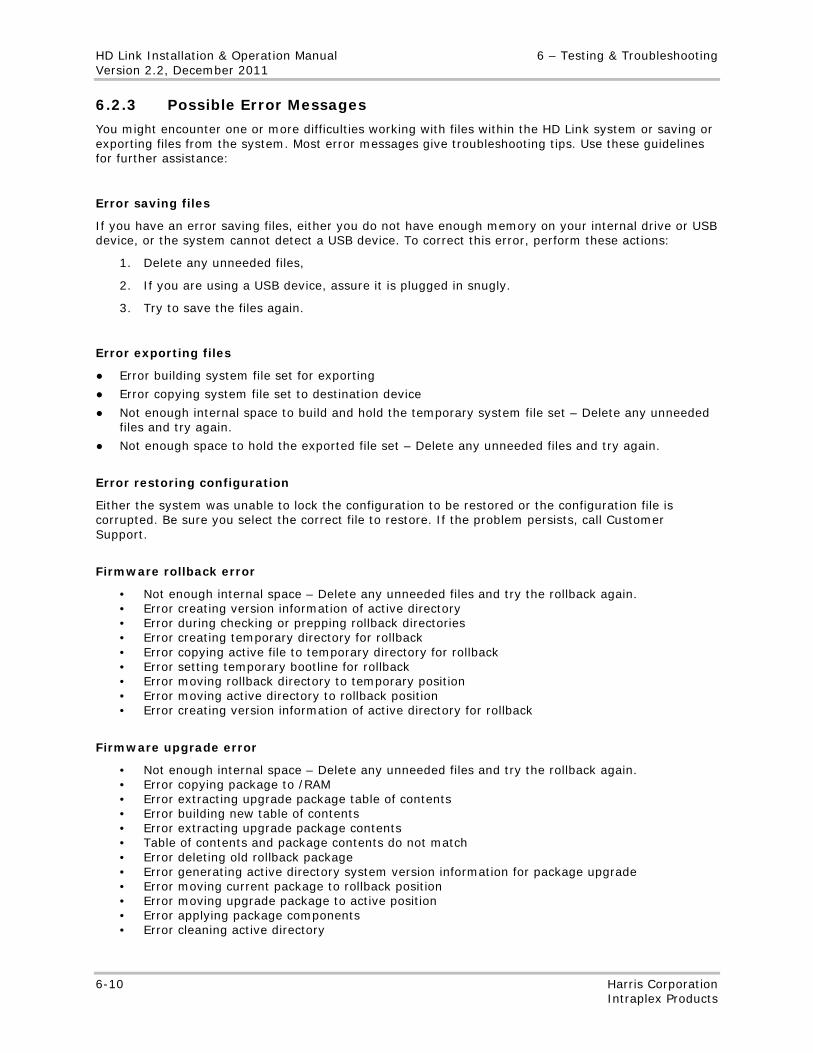
HD Link Installation & Operation Manual 6 – Testing & Troubleshooting Version 2.2, December 2011
6-10 Harris Corporation Intraplex Products
6.2.3 Possible Error Messages
You might encounter one or more difficulties working with files within the HD Link system or saving or exporting files from the system. Most error messages give troubleshooting tips. Use these guidelines for further assistance:
Error saving files
If you have an error saving files, either you do not have enough memory on your internal drive or USB device, or the system cannot detect a USB device. To correct this error, perform these actions:
1. Delete any unneeded files,
2. If you are using a USB device, assure it is plugged in snugly.
3. Try to save the files again.
Error exporting files
● Error building system file set for exporting
● Error copying system file set to destination device
● Not enough internal space to build and hold the temporary system file set – Delete any unneeded files and try again.
● Not enough space to hold the exported file set – Delete any unneeded files and try again.
Error restoring configuration
Either the system was unable to lock the configuration to be restored or the configuration file is corrupted. Be sure you select the correct file to restore. If the problem persists, call Customer Support.
Firmware rollback error
• Not enough internal space – Delete any unneeded files and try the rollback again. • Error creating version information of active directory • Error during checking or prepping rollback directories • Error creating temporary directory for rollback • Error copying active file to temporary directory for rollback • Error setting temporary bootline for rollback • Error moving rollback directory to temporary position • Error moving active directory to rollback position • Error creating version information of active directory for rollback
Firmware upgrade error
• Not enough internal space – Delete any unneeded files and try the rollback again. • Error copying package to /RAM • Error extracting upgrade package table of contents • Error building new table of contents • Error extracting upgrade package contents • Table of contents and package contents do not match • Error deleting old rollback package • Error generating active directory system version information for package upgrade • Error moving current package to rollback position • Error moving upgrade package to active position • Error applying package components • Error cleaning active directory
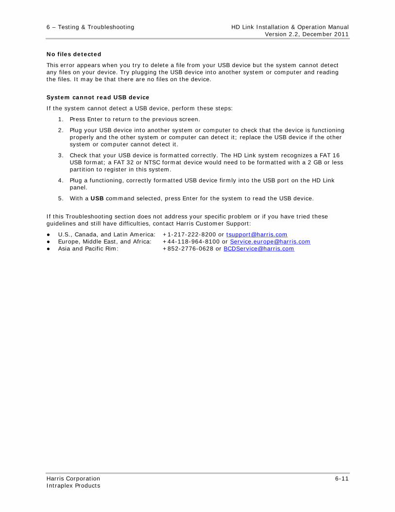
6 – Testing & Troubleshooting HD Link Installation & Operation Manual Version 2.2, December 2011
Harris Corporation 6-11 Intraplex Products
No files detected
This error appears when you try to delete a file from your USB device but the system cannot detect any files on your device. Try plugging the USB device into another system or computer and reading the files. It may be that there are no files on the device.
System cannot read USB device
If the system cannot detect a USB device, perform these steps:
1. Press Enter to return to the previous screen.
2. Plug your USB device into another system or computer to check that the device is functioning properly and the other system or computer can detect it; replace the USB device if the other system or computer cannot detect it.
3. Check that your USB device is formatted correctly. The HD Link system recognizes a FAT 16 USB format; a FAT 32 or NTSC format device would need to be formatted with a 2 GB or less partition to register in this system.
4. Plug a functioning, correctly formatted USB device firmly into the USB port on the HD Link panel.
5. With a USB command selected, press Enter for the system to read the USB device.
If this Troubleshooting section does not address your specific problem or if you have tried these guidelines and still have difficulties, contact Harris Customer Support:
● U.S., Canada, and Latin America: +1-217-222-8200 or [email protected] ● Europe, Middle East, and Africa: +44-118-964-8100 or [email protected] ● Asia and Pacific Rim: +852-2776-0628 or [email protected]

No header here
6-12 Harris Corporation Intraplex Products
This page is left blank intentionally.
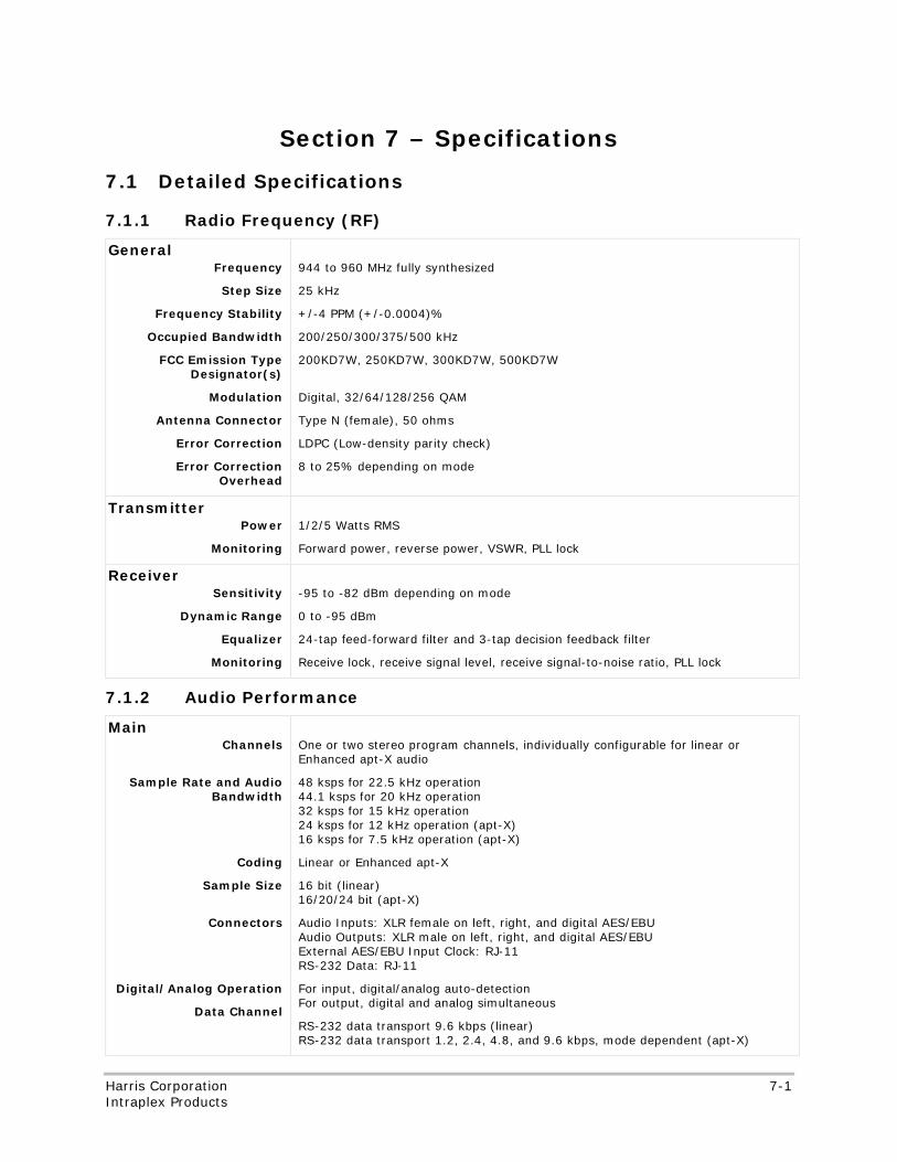
No header here
Harris Corporation 7-1 Intraplex Products
Section 7 – Specifications
7.1 Detailed Specifications
7.1.1 Radio Frequency (RF)
General Frequency
Step Size
Frequency Stability
Occupied Bandwidth
FCC Emission Type Designator(s)
Modulation
Antenna Connector
Error Correction
Error Correction Overhead
944 to 960 MHz fully synthesized
25 kHz
+/-4 PPM (+/-0.0004)%
200/250/300/375/500 kHz
200KD7W, 250KD7W, 300KD7W, 500KD7W
Digital, 32/64/128/256 QAM
Type N (female), 50 ohms
LDPC (Low-density parity check)
8 to 25% depending on mode
Transmitter Power
Monitoring
1/2/5 Watts RMS
Forward power, reverse power, VSWR, PLL lock
Receiver Sensitivity
Dynamic Range
Equalizer
Monitoring
-95 to -82 dBm depending on mode
0 to -95 dBm
24-tap feed-forward filter and 3-tap decision feedback filter
Receive lock, receive signal level, receive signal-to-noise ratio, PLL lock
7.1.2 Audio Performance
Main Channels
Sample Rate and Audio Bandwidth
Coding
Sample Size
Connectors
Digital/Analog Operation
Data Channel
One or two stereo program channels, individually configurable for linear or Enhanced apt-X audio
48 ksps for 22.5 kHz operation 44.1 ksps for 20 kHz operation 32 ksps for 15 kHz operation 24 ksps for 12 kHz operation (apt-X) 16 ksps for 7.5 kHz operation (apt-X)
Linear or Enhanced apt-X
16 bit (linear) 16/20/24 bit (apt-X)
Audio Inputs: XLR female on left, right, and digital AES/EBU Audio Outputs: XLR male on left, right, and digital AES/EBU External AES/EBU Input Clock: RJ-11 RS-232 Data: RJ-11
For input, digital/analog auto-detection For output, digital and analog simultaneous
RS-232 data transport 9.6 kbps (linear) RS-232 data transport 1.2, 2.4, 4.8, and 9.6 kbps, mode dependent (apt-X)
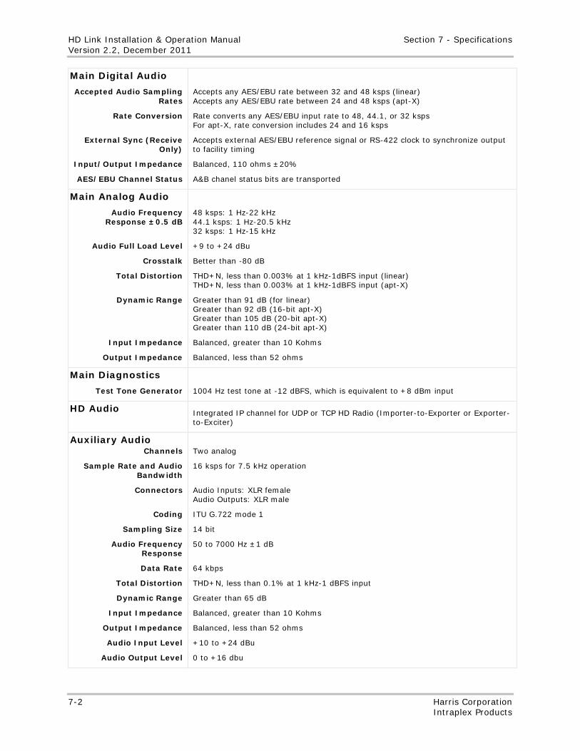
HD Link Installation & Operation Manual Section 7 - Specifications Version 2.2, December 2011
7-2 Harris Corporation Intraplex Products
Main Digital Audio
Accepted Audio Sampling Rates
Rate Conversion
External Sync (Receive Only)
Input/Output Impedance
AES/EBU Channel Status
Accepts any AES/EBU rate between 32 and 48 ksps (linear) Accepts any AES/EBU rate between 24 and 48 ksps (apt-X)
Rate converts any AES/EBU input rate to 48, 44.1, or 32 ksps For apt-X, rate conversion includes 24 and 16 ksps
Accepts external AES/EBU reference signal or RS-422 clock to synchronize output to facility timing
Balanced, 110 ohms ±20%
A&B chanel status bits are transported
Main Analog Audio
Audio Frequency Response ±0.5 dB
Audio Full Load Level
Crosstalk
Total Distortion
Dynamic Range
Input Impedance
Output Impedance
48 ksps: 1 Hz-22 kHz 44.1 ksps: 1 Hz-20.5 kHz 32 ksps: 1 Hz-15 kHz
+9 to +24 dBu
Better than -80 dB
THD+N, less than 0.003% at 1 kHz-1dBFS input (linear) THD+N, less than 0.003% at 1 kHz-1dBFS input (apt-X)
Greater than 91 dB (for linear) Greater than 92 dB (16-bit apt-X) Greater than 105 dB (20-bit apt-X) Greater than 110 dB (24-bit apt-X)
Balanced, greater than 10 Kohms
Balanced, less than 52 ohms
Main Diagnostics
Test Tone Generator
1004 Hz test tone at -12 dBFS, which is equivalent to +8 dBm input
HD Audio Integrated IP channel for UDP or TCP HD Radio (Importer-to-Exporter or Exporter-to-Exciter)
Auxiliary Audio Channels
Sample Rate and Audio Bandwidth
Connectors
Coding
Sampling Size
Audio Frequency Response
Data Rate
Total Distortion
Dynamic Range
Input Impedance
Output Impedance
Audio Input Level
Audio Output Level
Two analog
16 ksps for 7.5 kHz operation
Audio Inputs: XLR female Audio Outputs: XLR male
ITU G.722 mode 1
14 bit
50 to 7000 Hz ±1 dB
64 kbps
THD+N, less than 0.1% at 1 kHz-1 dBFS input
Greater than 65 dB
Balanced, greater than 10 Kohms
Balanced, less than 52 ohms
+10 to +24 dBu
0 to +16 dbu
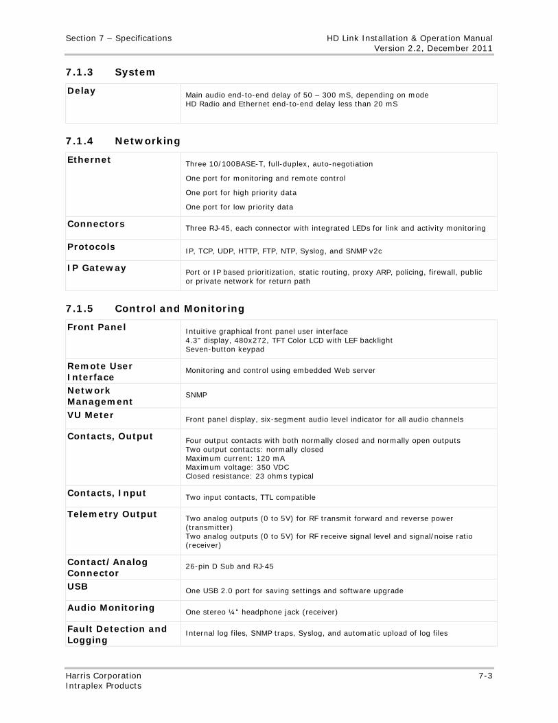
Section 7 – Specifications HD Link Installation & Operation Manual Version 2.2, December 2011
Harris Corporation 7-3 Intraplex Products
7.1.3 System
Delay Main audio end-to-end delay of 50 – 300 mS, depending on mode HD Radio and Ethernet end-to-end delay less than 20 mS
7.1.4 Networking
Ethernet Three 10/100BASE-T, full-duplex, auto-negotiation
One port for monitoring and remote control
One port for high priority data
One port for low priority data
Connectors Three RJ-45, each connector with integrated LEDs for link and activity monitoring
Protocols IP, TCP, UDP, HTTP, FTP, NTP, Syslog, and SNMP v2c
IP Gateway Port or IP based prioritization, static routing, proxy ARP, policing, firewall, public or private network for return path
7.1.5 Control and Monitoring
Front Panel Intuitive graphical front panel user interface 4.3" display, 480x272, TFT Color LCD with LEF backlight Seven-button keypad
Remote User Interface
Monitoring and control using embedded Web server
Network Management
SNMP
VU Meter Front panel display, six-segment audio level indicator for all audio channels
Contacts, Output Four output contacts with both normally closed and normally open outputs Two output contacts: normally closed Maximum current: 120 mA Maximum voltage: 350 VDC Closed resistance: 23 ohms typical
Contacts, Input Two input contacts, TTL compatible
Telemetry Output Two analog outputs (0 to 5V) for RF transmit forward and reverse power (transmitter) Two analog outputs (0 to 5V) for RF receive signal level and signal/noise ratio (receiver)
Contact/Analog Connector
26-pin D Sub and RJ-45
USB One USB 2.0 port for saving settings and software upgrade
Audio Monitoring One stereo ¼" headphone jack (receiver)
Fault Detection and Logging
Internal log files, SNMP traps, Syslog, and automatic upload of log files
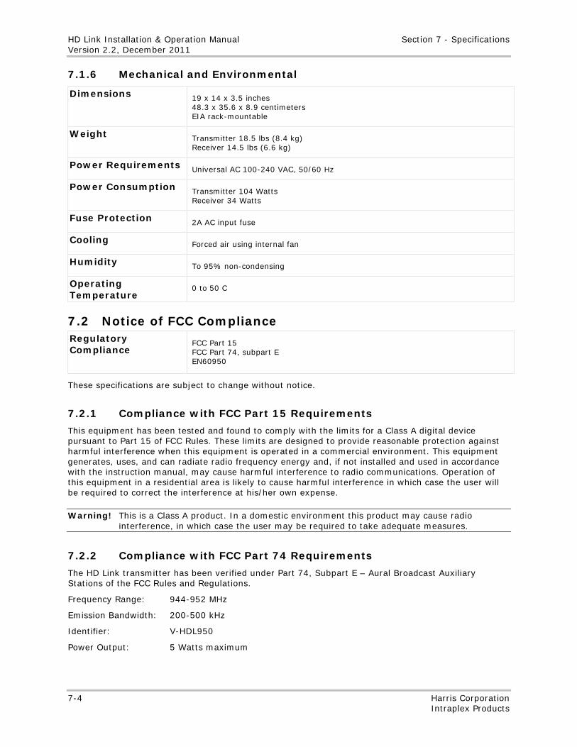
HD Link Installation & Operation Manual Section 7 - Specifications Version 2.2, December 2011
7-4 Harris Corporation Intraplex Products
7.1.6 Mechanical and Environmental
Dimensions 19 x 14 x 3.5 inches 48.3 x 35.6 x 8.9 centimeters EIA rack-mountable
Weight Transmitter 18.5 lbs (8.4 kg) Receiver 14.5 lbs (6.6 kg)
Power Requirements Universal AC 100-240 VAC, 50/60 Hz
Power Consumption Transmitter 104 Watts Receiver 34 Watts
Fuse Protection 2A AC input fuse
Cooling Forced air using internal fan
Humidity To 95% non-condensing
Operating Temperature
0 to 50 C
7.2 Notice of FCC Compliance Regulatory Compliance
FCC Part 15 FCC Part 74, subpart E EN60950
These specifications are subject to change without notice.
7.2.1 Compliance with FCC Part 15 Requirements
This equipment has been tested and found to comply with the limits for a Class A digital device pursuant to Part 15 of FCC Rules. These limits are designed to provide reasonable protection against harmful interference when this equipment is operated in a commercial environment. This equipment generates, uses, and can radiate radio frequency energy and, if not installed and used in accordance with the instruction manual, may cause harmful interference to radio communications. Operation of this equipment in a residential area is likely to cause harmful interference in which case the user will be required to correct the interference at his/her own expense.
Warning! This is a Class A product. In a domestic environment this product may cause radio interference, in which case the user may be required to take adequate measures.
7.2.2 Compliance with FCC Part 74 Requirements
The HD Link transmitter has been verified under Part 74, Subpart E – Aural Broadcast Auxiliary Stations of the FCC Rules and Regulations.
Frequency Range: 944-952 MHz
Emission Bandwidth: 200-500 kHz
Identifier: V-HDL950
Power Output: 5 Watts maximum
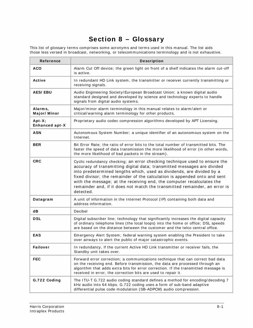
No header
Harris Corporation 8-1 Intraplex Products
Section 8 – Glossary This list of glossary terms comprises some acronyms and terms used in this manual. The list aids those less versed in broadcast, networking, or telecommunications terminology and is not exhaustive.
Reference Description
ACO Alarm Cut Off device; the green light on front of a shelf indicates the alarm cut-off is active.
Active In redundant HD Link system, the transmitter or receiver currently transmitting or receiving signals.
AES/EBU Audio Engineering Society/European Broadcast Union; a known digital audio standard designed and developed by science and technology experts to handle signals from digital audio systems.
Alarms, Major/Minor
Major/minor alarm terminology in this manual relates to alarm/alert or critical/warning alarm terminology for other products.
Apt-X; Enhanced apt-X
Proprietary audio codec compression algorithms developed by APT Licensing.
ASN Autonomous System Number; a unique identifier of an autonomous system on the Internet.
BER Bit Error Rate; the ratio of error bits to the total number of transmitted bits. The faster the speed of data transmission the more likelihood of error (in other words, the more likelihood of bad packets in the stream).
CRC Cyclic redundancy checking; an error checking technique used to ensure the accuracy of transmitting digital data; transmitted messages are divided into predetermined lengths which, used as dividends, are divided by a fixed divisor; the remainder of the calculation is appended onto and sent with the message; at the receiving end, the computer recalculates the remainder and, if it does not match the transmitted remainder, an error is detected.
Datagram A unit of information in the Internet Protocol (IP) containing both data and address information.
dB Decibel
DSL Digital subscriber line; technology that significantly increases the digital capacity of ordinary telephone lines (the local loops) into the home or office; DSL speeds are based on the distance between the customer and the telco central office.
EAS Emergency Alert System; federal warning system enabling the President to take over airways to alert the public of major catastrophic events.
Failover In redundancy, if the current Active HD Link transmitter or receiver fails, the Standby unit takes over.
FEC Forward error correction; a communications technique that can correct bad data on the receiving end. Before transmission, the data are processed through an algorithm that adds extra bits for error correction. If the transmitted message is received in error, the correction bits are used to repair it.
G.722 Coding The ITU-T G.722 audio coding standard defines a method for encoding/decoding 7 kHz audio into 64 kbps. G.722 coding uses a form of sub-band adaptive differential pulse code modulation (SB-ADPCM) audio compression.
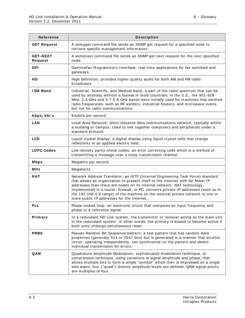
HD Link Installation & Operation Manual 8 – Glossary Version 2.2, December 2011
8-2 Harris Corporation Intraplex Products
Reference Description
GET Request A snmpget command file sends an SNMP get request for a specified node to retrieve specific management information.
GET-NEXT Request
A snmpnext command file sends an SNMP get next request for the next specified node.
GPI GammaFax Programmers Interface; real-time applications for fax switched and gateways.
HD High definition; provides higher quality audio for both AM and FM radio broadcasts.
ISM Band Industrial, Scientific, and Medical band; a part of the radio spectrum that can be used by anybody without a license in most countries; in the U.S., the 902-928 MHz, 2.4 GHz and 5.7-5.8 GHz bands were initially used for machines that emitted radio frequencies, such as RF welders, industrial heaters, and microwave ovens, but not for radio communications.
Kbps; kb/s Kilobits per second
LAN Local Area Network; short-distance data communications network, typically within a building or campus. Used to link together computers and peripherals under a standard protocol.
LCD Liquid crystal display: a digital display using liquid crystal cells that change reflectivity in an applied electric field.
LDPC Codes Low-density parity-check codes; an error correcting code which is a method of transmitting a message over a noisy transmission channel.
Mbps Megabits per second
MHz Megahertz
NAT Network Address Translator; an IETF (Internal Engineering Task Force) standard that allows an organization to present itself to the Internet with far fewer IP addresses than there are nodes on its internal network; NAT technology, implemented in a router, firewall, or PC, converts private IP addresses (such as in the 192.168.0.0 range) of the machine on the internal private network to one or more public IP addresses for the Internet.
PLL Phase-locked loop; an electronic circuit that compares an input frequency and phase to a reference signal.
Primary In a redundant HD Link system, the transmitter or receiver acting as the main unit in the redundant system; in other words, the primary is biased to become active if both units undergo simultaneous reset.
PRBS Pseudo Random Bit Sequence/pattern; a test pattern that has random data properties (generally 511 or 2047 bits) but is generated in a manner that another circuit, operating independently, can synchronize on the pattern and detect individual transmission bit errors.
QAM Quadrature Amplitude Modulation; sophisticated modulation technique, or compression technique, using variations in signal amplitude and phase, that allows multiple bits to form a single “symbol” which then is impressed on a single sine wave; four (“quad”) distinct amplitude levels are defined. QAM signal points are multiples of four.
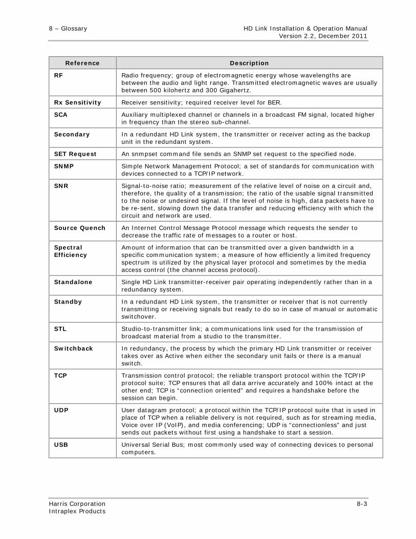
8 – Glossary HD Link Installation & Operation Manual Version 2.2, December 2011
Harris Corporation 8-3 Intraplex Products
Reference Description
RF Radio frequency; group of electromagnetic energy whose wavelengths are between the audio and light range. Transmitted electromagnetic waves are usually between 500 kilohertz and 300 Gigahertz.
Rx Sensitivity Receiver sensitivity; required receiver level for BER.
SCA Auxiliary multiplexed channel or channels in a broadcast FM signal, located higher in frequency than the stereo sub-channel.
Secondary In a redundant HD Link system, the transmitter or receiver acting as the backup unit in the redundant system.
SET Request An snmpset command file sends an SNMP set request to the specified node.
SNMP Simple Network Management Protocol; a set of standards for communication with devices connected to a TCP/IP network.
SNR Signal-to-noise ratio; measurement of the relative level of noise on a circuit and, therefore, the quality of a transmission; the ratio of the usable signal transmitted to the noise or undesired signal. If the level of noise is high, data packets have to be re-sent, slowing down the data transfer and reducing efficiency with which the circuit and network are used.
Source Quench An Internet Control Message Protocol message which requests the sender to decrease the traffic rate of messages to a router or host.
Spectral Efficiency
Amount of information that can be transmitted over a given bandwidth in a specific communication system; a measure of how efficiently a limited frequency spectrum is utilized by the physical layer protocol and sometimes by the media access control (the channel access protocol).
Standalone Single HD Link transmitter-receiver pair operating independently rather than in a redundancy system.
Standby In a redundant HD Link system, the transmitter or receiver that is not currently transmitting or receiving signals but ready to do so in case of manual or automatic switchover.
STL Studio-to-transmitter link; a communications link used for the transmission of broadcast material from a studio to the transmitter.
Switchback In redundancy, the process by which the primary HD Link transmitter or receiver takes over as Active when either the secondary unit fails or there is a manual switch.
TCP Transmission control protocol; the reliable transport protocol within the TCP/IP protocol suite; TCP ensures that all data arrive accurately and 100% intact at the other end; TCP is “connection oriented” and requires a handshake before the session can begin.
UDP User datagram protocol; a protocol within the TCP/IP protocol suite that is used in place of TCP when a reliable delivery is not required, such as for streaming media, Voice over IP (VoIP), and media conferencing; UDP is “connectionless” and just sends out packets without first using a handshake to start a session.
USB Universal Serial Bus; most commonly used way of connecting devices to personal computers.
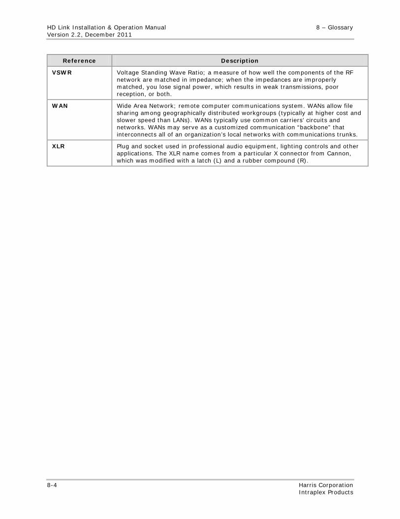
HD Link Installation & Operation Manual 8 – Glossary Version 2.2, December 2011
8-4 Harris Corporation Intraplex Products
Reference Description
VSWR Voltage Standing Wave Ratio; a measure of how well the components of the RF network are matched in impedance; when the impedances are improperly matched, you lose signal power, which results in weak transmissions, poor reception, or both.
WAN Wide Area Network; remote computer communications system. WANs allow file sharing among geographically distributed workgroups (typically at higher cost and slower speed than LANs). WANs typically use common carriers’ circuits and networks. WANs may serve as a customized communication “backbone” that interconnects all of an organization’s local networks with communications trunks.
XLR Plug and socket used in professional audio equipment, lighting controls and other applications. The XLR name comes from a particular X connector from Cannon, which was modified with a latch (L) and a rubber compound (R).
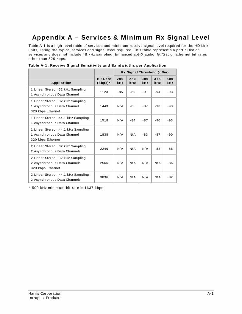
No header here
Harris Corporation A-1 Intraplex Products
Appendix A – Services & Minimum Rx Signal Level Table A-1 is a high-level table of services and minimum receive signal level required for the HD Link units, listing the typical services and signal level required. This table represents a partial list of services and does not include 48 kHz sampling, Enhanced apt-X audio, G.722, or Ethernet bit rates other than 320 kbps.
Table A-1. Receive Signal Sensitivity and Bandwidths per Application
Application Bit Rate (kbps)*
Rx Signal Threshold (dBm)
200kHz
250 kHz
300 kHz
375 kHz
500 kHz
1 Linear Stereo, 32 kHz Sampling
1 Asynchronous Data Channel 1123 -85 -89 -91 -94 -93
1 Linear Stereo, 32 kHz Sampling
1 Asynchronous Data Channel
320 kbps Ethernet
1443 N/A -85 -87 -90 -93
1 Linear Stereo, 44.1 kHz Sampling
1 Asynchronous Data Channel 1518 N/A -84 -87 -90 -93
1 Linear Stereo, 44.1 kHz Sampling
1 Asynchronous Data Channel
320 kbps Ethernet
1838 N/A N/A -83 -87 -90
2 Linear Stereo, 32 kHz Sampling
2 Asynchronous Data Channels 2246 N/A N/A N/A -83 -88
2 Linear Stereo, 32 kHz Sampling
2 Asynchronous Data Channels
320 kbps Ethernet
2566 N/A N/A N/A N/A -86
2 Linear Stereo, 44.1 kHz Sampling
2 Asynchronous Data Channels 3036 N/A N/A N/A N/A -82
* 500 kHz minimum bit rate is 1637 kbps

No header here
A-2 Harris Corporation Intraplex Products
This page is left blank intentionally.
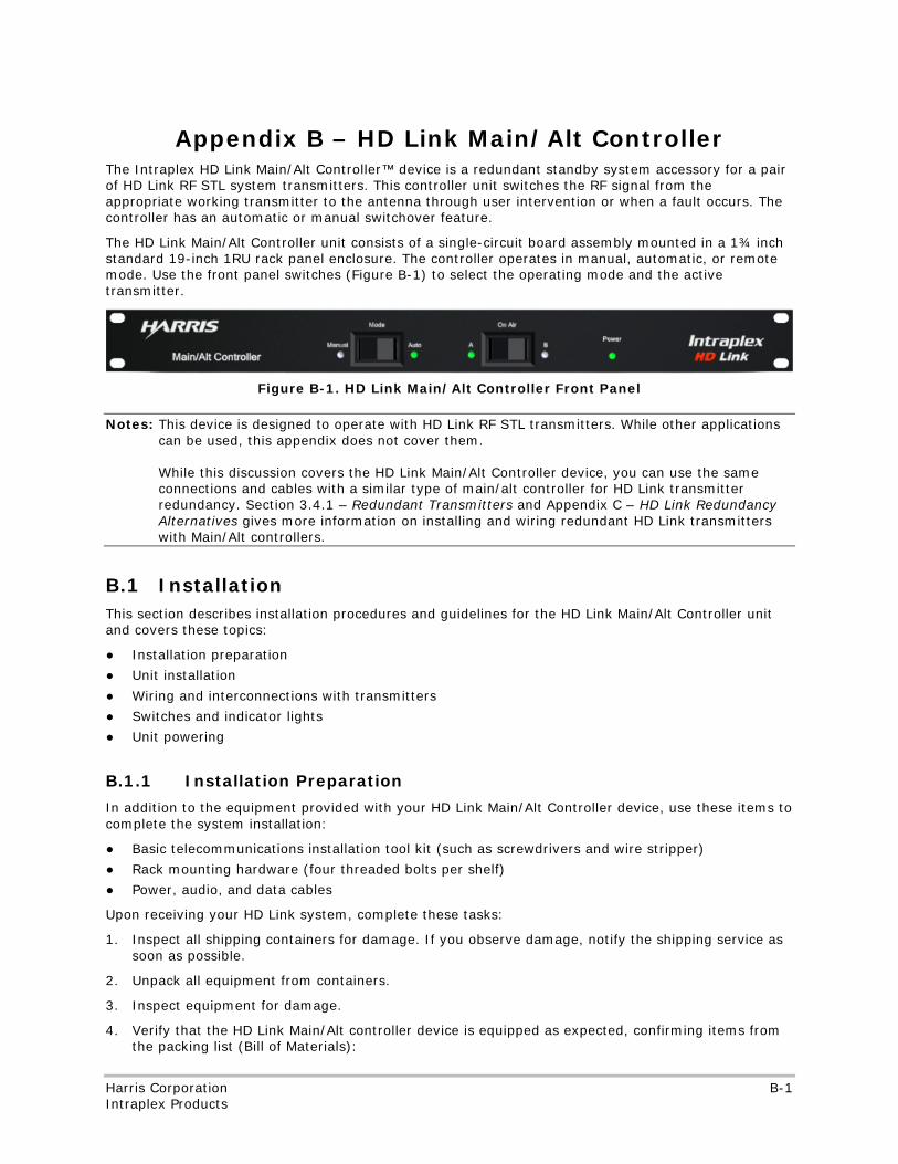
No header
Harris Corporation B-1 Intraplex Products
Appendix B – HD Link Main/Alt Controller The Intraplex HD Link Main/Alt Controller™ device is a redundant standby system accessory for a pair of HD Link RF STL system transmitters. This controller unit switches the RF signal from the appropriate working transmitter to the antenna through user intervention or when a fault occurs. The controller has an automatic or manual switchover feature.
The HD Link Main/Alt Controller unit consists of a single-circuit board assembly mounted in a 1¾ inch standard 19-inch 1RU rack panel enclosure. The controller operates in manual, automatic, or remote mode. Use the front panel switches (Figure B-1) to select the operating mode and the active transmitter.
Figure B-1. HD Link Main/Alt Controller Front Panel
Notes: This device is designed to operate with HD Link RF STL transmitters. While other applications can be used, this appendix does not cover them. While this discussion covers the HD Link Main/Alt Controller device, you can use the same connections and cables with a similar type of main/alt controller for HD Link transmitter redundancy. Section 3.4.1 – Redundant Transmitters and Appendix C – HD Link Redundancy Alternatives gives more information on installing and wiring redundant HD Link transmitters with Main/Alt controllers.
B.1 Installation This section describes installation procedures and guidelines for the HD Link Main/Alt Controller unit and covers these topics:
● Installation preparation
● Unit installation
● Wiring and interconnections with transmitters
● Switches and indicator lights
● Unit powering
B.1.1 Installation Preparation
In addition to the equipment provided with your HD Link Main/Alt Controller device, use these items to complete the system installation:
● Basic telecommunications installation tool kit (such as screwdrivers and wire stripper)
● Rack mounting hardware (four threaded bolts per shelf)
● Power, audio, and data cables
Upon receiving your HD Link system, complete these tasks:
1. Inspect all shipping containers for damage. If you observe damage, notify the shipping service as soon as possible.
2. Unpack all equipment from containers.
3. Inspect equipment for damage.
4. Verify that the HD Link Main/Alt controller device is equipped as expected, confirming items from the packing list (Bill of Materials):
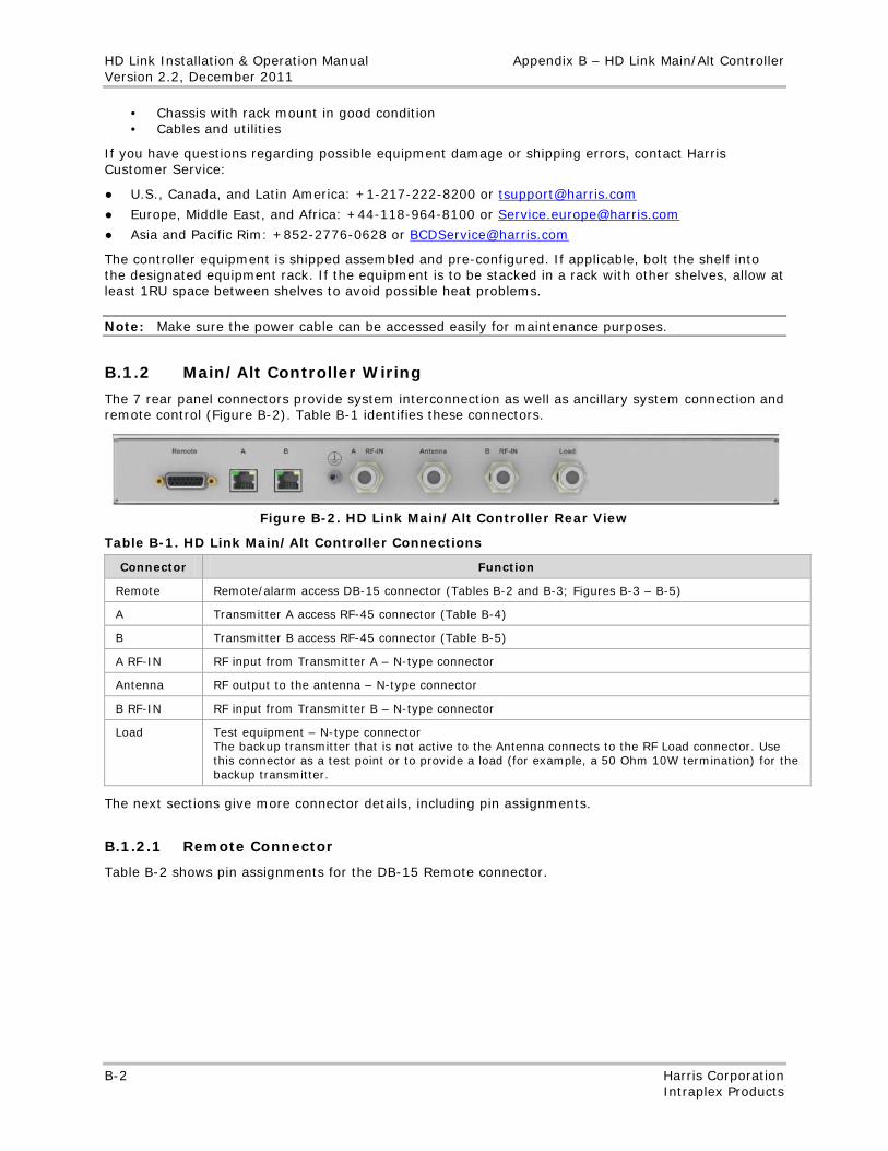
HD Link Installation & Operation Manual Appendix B – HD Link Main/Alt Controller Version 2.2, December 2011
B-2 Harris Corporation Intraplex Products
• Chassis with rack mount in good condition • Cables and utilities
If you have questions regarding possible equipment damage or shipping errors, contact Harris Customer Service:
● U.S., Canada, and Latin America: +1-217-222-8200 or [email protected]
● Europe, Middle East, and Africa: +44-118-964-8100 or [email protected]
● Asia and Pacific Rim: +852-2776-0628 or [email protected]
The controller equipment is shipped assembled and pre-configured. If applicable, bolt the shelf into the designated equipment rack. If the equipment is to be stacked in a rack with other shelves, allow at least 1RU space between shelves to avoid possible heat problems.
Note: Make sure the power cable can be accessed easily for maintenance purposes.
B.1.2 Main/Alt Controller Wiring
The 7 rear panel connectors provide system interconnection as well as ancillary system connection and remote control (Figure B-2). Table B-1 identifies these connectors.
Figure B-2. HD Link Main/Alt Controller Rear View
Table B-1. HD Link Main/Alt Controller Connections
Connector Function
Remote Remote/alarm access DB-15 connector (Tables B-2 and B-3; Figures B-3 – B-5)
A Transmitter A access RF-45 connector (Table B-4)
B Transmitter B access RF-45 connector (Table B-5)
A RF-IN RF input from Transmitter A – N-type connector
Antenna RF output to the antenna – N-type connector
B RF-IN RF input from Transmitter B – N-type connector
Load Test equipment – N-type connector The backup transmitter that is not active to the Antenna connects to the RF Load connector. Use this connector as a test point or to provide a load (for example, a 50 Ohm 10W termination) for the backup transmitter.
The next sections give more connector details, including pin assignments.
B.1.2.1 Remote Connector
Table B-2 shows pin assignments for the DB-15 Remote connector.
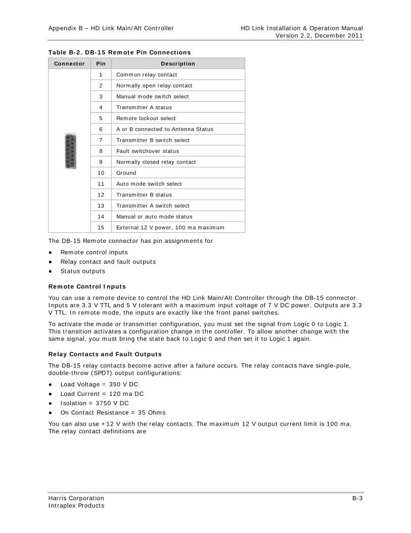
Appendix B – HD Link Main/Alt Controller HD Link Installation & Operation Manual Version 2.2, December 2011
Harris Corporation B-3 Intraplex Products
Table B-2. DB-15 Remote Pin Connections
Connector Pin Description
1 Common relay contact
2 Normally open relay contact
3 Manual mode switch select
4 Transmitter A status
5 Remote lockout select
6 A or B connected to Antenna Status
7 Transmitter B switch select
8 Fault switchover status
9 Normally closed relay contact
10 Ground
11 Auto mode switch select
12 Transmitter B status
13 Transmitter A switch select
14 Manual or auto mode status
15 External 12 V power, 100 ma maximum
The DB-15 Remote connector has pin assignments for
● Remote control inputs
● Relay contact and fault outputs
● Status outputs
Remote Control Inputs
You can use a remote device to control the HD Link Main/Alt Controller through the DB-15 connector. Inputs are 3.3 V TTL and 5 V tolerant with a maximum input voltage of 7 V DC power. Outputs are 3.3 V TTL. In remote mode, the inputs are exactly like the front panel switches.
To activate the mode or transmitter configuration, you must set the signal from Logic 0 to Logic 1. This transition activates a configuration change in the controller. To allow another change with the same signal, you must bring the state back to Logic 0 and then set it to Logic 1 again.
Relay Contacts and Fault Outputs
The DB-15 relay contacts become active after a failure occurs. The relay contacts have single-pole, double-throw (SPDT) output configurations:
● Load Voltage = 350 V DC
● Load Current = 120 ma DC
● Isolation = 3750 V DC
● On Contact Resistance = 35 Ohms
You can also use +12 V with the relay contacts. The maximum 12 V output current limit is 100 ma. The relay contact definitions are
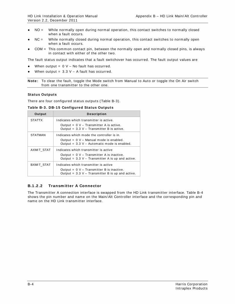
HD Link Installation & Operation Manual Appendix B – HD Link Main/Alt Controller Version 2.2, December 2011
B-4 Harris Corporation Intraplex Products
● NO = While normally open during normal operation, this contact switches to normally closed when a fault occurs.
● NC = While normally closed during normal operation, this contact switches to normally open when a fault occurs.
● COM = This common contact pin, between the normally open and normally closed pins, is always in contact with either of the other two.
The fault status output indicates that a fault switchover has occurred. The fault output values are
● When output = 0 V – No fault has occurred.
● When output = 3.3 V – A fault has occurred.
Note: To clear the fault, toggle the Mode switch from Manual to Auto or toggle the On Air switch from one transmitter to the other one.
Status Outputs
There are four configured status outputs (Table B-3).
Table B-3. DB-15 Configured Status Outputs
Output Description
STATTX Indicates which transmitter is active.
Output = 0 V – Transmitter A is active. Output = 3.3 V – Transmitter B is active.
STATMAN Indicates which mode the controller is in.
Output = 0 V – Manual mode is enabled. Output = 3.3 V – Automatic mode is enabled.
AXMIT_STAT Indicates which transmitter is active
Output = 0 V – Transmitter A is inactive. Output = 3.3 V – Transmitter A is up and active.
BXMIT_STAT Indicates which transmitter is active
Output = 0 V – Transmitter B is inactive. Output = 3.3 V – Transmitter B is up and active.
B.1.2.2 Transmitter A Connector
The Transmitter A connection interface is swapped from the HD Link transmitter interface. Table B-4 shows the pin number and name on the Main/Alt Controller interface and the corresponding pin and name on the HD Link transmitter interface.
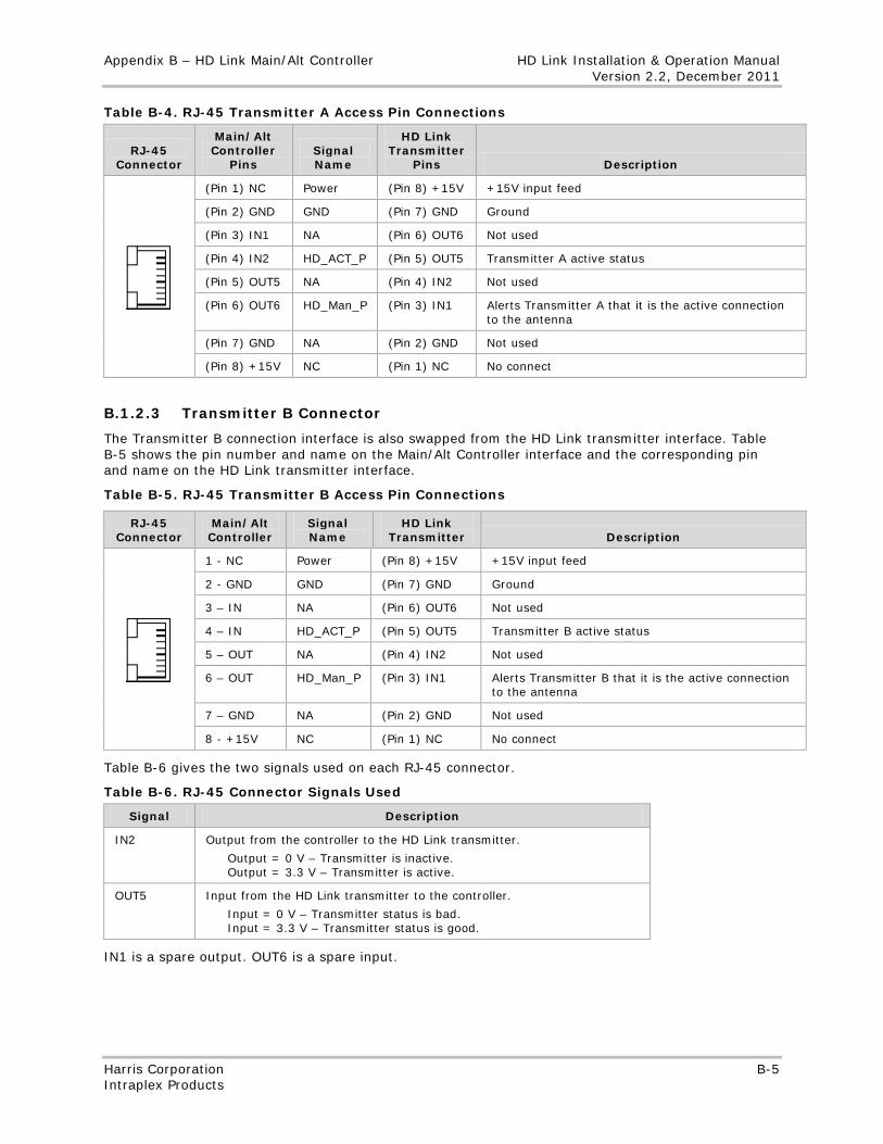
Appendix B – HD Link Main/Alt Controller HD Link Installation & Operation Manual Version 2.2, December 2011
Harris Corporation B-5 Intraplex Products
Table B-4. RJ-45 Transmitter A Access Pin Connections
RJ-45 Connector
Main/Alt Controller
Pins Signal Name
HD Link Transmitter
Pins Description
(Pin 1) NC Power (Pin 8) +15V +15V input feed
(Pin 2) GND GND (Pin 7) GND Ground
(Pin 3) IN1 NA (Pin 6) OUT6 Not used
(Pin 4) IN2 HD_ACT_P (Pin 5) OUT5 Transmitter A active status
(Pin 5) OUT5 NA (Pin 4) IN2 Not used
(Pin 6) OUT6 HD_Man_P (Pin 3) IN1 Alerts Transmitter A that it is the active connection to the antenna
(Pin 7) GND NA (Pin 2) GND Not used
(Pin 8) +15V NC (Pin 1) NC No connect
B.1.2.3 Transmitter B Connector
The Transmitter B connection interface is also swapped from the HD Link transmitter interface. Table B-5 shows the pin number and name on the Main/Alt Controller interface and the corresponding pin and name on the HD Link transmitter interface.
Table B-5. RJ-45 Transmitter B Access Pin Connections
RJ-45 Connector
Main/Alt Controller
Signal Name
HD Link Transmitter Description
1 - NC Power (Pin 8) +15V +15V input feed
2 - GND GND (Pin 7) GND Ground
3 – IN NA (Pin 6) OUT6 Not used
4 – IN HD_ACT_P (Pin 5) OUT5 Transmitter B active status
5 – OUT NA (Pin 4) IN2 Not used
6 – OUT HD_Man_P (Pin 3) IN1 Alerts Transmitter B that it is the active connection to the antenna
7 – GND NA (Pin 2) GND Not used
8 - +15V NC (Pin 1) NC No connect
Table B-6 gives the two signals used on each RJ-45 connector.
Table B-6. RJ-45 Connector Signals Used
Signal Description
IN2 Output from the controller to the HD Link transmitter.
Output = 0 V – Transmitter is inactive. Output = 3.3 V – Transmitter is active.
OUT5 Input from the HD Link transmitter to the controller.
Input = 0 V – Transmitter status is bad. Input = 3.3 V – Transmitter status is good.
IN1 is a spare output. OUT6 is a spare input.
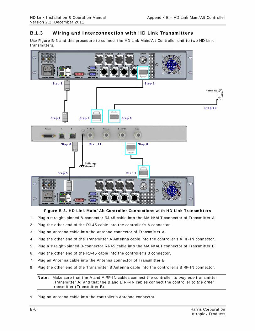
HD Link Installation & Operation Manual Appendix B – HD Link Main/Alt Controller Version 2.2, December 2011
B-6 Harris Corporation Intraplex Products
B.1.3 Wiring and Interconnection with HD Link Transmitters
Use Figure B-3 and this procedure to connect the HD Link Main/Alt Controller unit to two HD Link transmitters.
Step 1
Step 2
Step 3
Step 4
Step 5
Step 6
Step 7
Step 8
Step 9
Step 11
Step 10
Antenna
Building Ground
Figure B-3. HD Link Main/Alt Controller Connections with HD Link Transmitters
1. Plug a straight-pinned 8-connector RJ-45 cable into the MAIN/ALT connector of Transmitter A.
2. Plug the other end of the RJ-45 cable into the controller’s A connector.
3. Plug an Antenna cable into the Antenna connector of Transmitter A.
4. Plug the other end of the Transmitter A Antenna cable into the controller’s A RF-IN connector.
5. Plug a straight-pinned 8-connector RJ-45 cable into the MAIN/ALT connector of Transmitter B.
6. Plug the other end of the RJ-45 cable into the controller’s B connector.
7. Plug an Antenna cable into the Antenna connector of Transmitter B.
8. Plug the other end of the Transmitter B Antenna cable into the controller’s B RF-IN connector.
Note: Make sure that the A and A RF-IN cables connect the controller to only one transmitter (Transmitter A) and that the B and B RF-IN cables connect the controller to the other transmitter (Transmitter B).
9. Plug an Antenna cable into the controller’s Antenna connector.
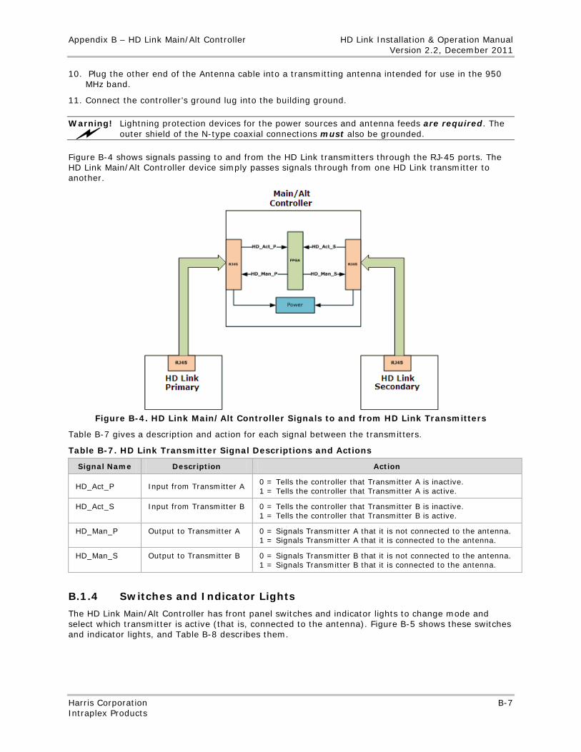
Appendix B – HD Link Main/Alt Controller HD Link Installation & Operation Manual Version 2.2, December 2011
Harris Corporation B-7 Intraplex Products
10. Plug the other end of the Antenna cable into a transmitting antenna intended for use in the 950 MHz band.
11. Connect the controller’s ground lug into the building ground.
Warning! Lightning protection devices for the power sources and antenna feeds are required. The outer shield of the N-type coaxial connections must also be grounded.
Figure B-4 shows signals passing to and from the HD Link transmitters through the RJ-45 ports. The HD Link Main/Alt Controller device simply passes signals through from one HD Link transmitter to another.
Figure B-4. HD Link Main/Alt Controller Signals to and from HD Link Transmitters
Table B-7 gives a description and action for each signal between the transmitters.
Table B-7. HD Link Transmitter Signal Descriptions and Actions
Signal Name Description Action
HD_Act_P Input from Transmitter A 0 = Tells the controller that Transmitter A is inactive. 1 = Tells the controller that Transmitter A is active.
HD_Act_S Input from Transmitter B 0 = Tells the controller that Transmitter B is inactive. 1 = Tells the controller that Transmitter B is active.
HD_Man_P Output to Transmitter A 0 = Signals Transmitter A that it is not connected to the antenna. 1 = Signals Transmitter A that it is connected to the antenna.
HD_Man_S Output to Transmitter B 0 = Signals Transmitter B that it is not connected to the antenna. 1 = Signals Transmitter B that it is connected to the antenna.
B.1.4 Switches and Indicator Lights
The HD Link Main/Alt Controller has front panel switches and indicator lights to change mode and select which transmitter is active (that is, connected to the antenna). Figure B-5 shows these switches and indicator lights, and Table B-8 describes them.
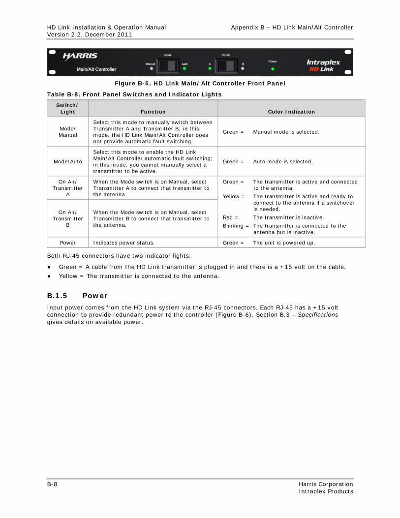
HD Link Installation & Operation Manual Appendix B – HD Link Main/Alt Controller Version 2.2, December 2011
B-8 Harris Corporation Intraplex Products
Figure B-5. HD Link Main/Alt Controller Front Panel
Table B-8. Front Panel Switches and Indicator Lights
Switch/ Light Function Color Indication
Mode/ Manual
Select this mode to manually switch between Transmitter A and Transmitter B; in this mode, the HD Link Main/Alt Controller does not provide automatic fault switching.
Green = Manual mode is selected.
Mode/Auto
Select this mode to enable the HD Link Main/Alt Controller automatic fault switching; in this mode, you cannot manually select a transmitter to be active.
Green = Auto mode is selected.
On Air/ Transmitter
A
When the Mode switch is on Manual, select Transmitter A to connect that transmitter to the antenna.
Green = The transmitter is active and connected to the antenna.
Yellow = The transmitter is active and ready to connect to the antenna if a switchover is needed.
Red = The transmitter is inactive.
Blinking = The transmitter is connected to the antenna but is inactive.
On Air/ Transmitter
B
When the Mode switch is on Manual, select Transmitter B to connect that transmitter to the antenna.
Power Indicates power status. Green = The unit is powered up.
Both RJ-45 connectors have two indicator lights:
● Green = A cable from the HD Link transmitter is plugged in and there is a +15 volt on the cable.
● Yellow = The transmitter is connected to the antenna.
B.1.5 Power
Input power comes from the HD Link system via the RJ-45 connectors. Each RJ-45 has a +15 volt connection to provide redundant power to the controller (Figure B-6). Section B.3 – Specifications gives details on available power.
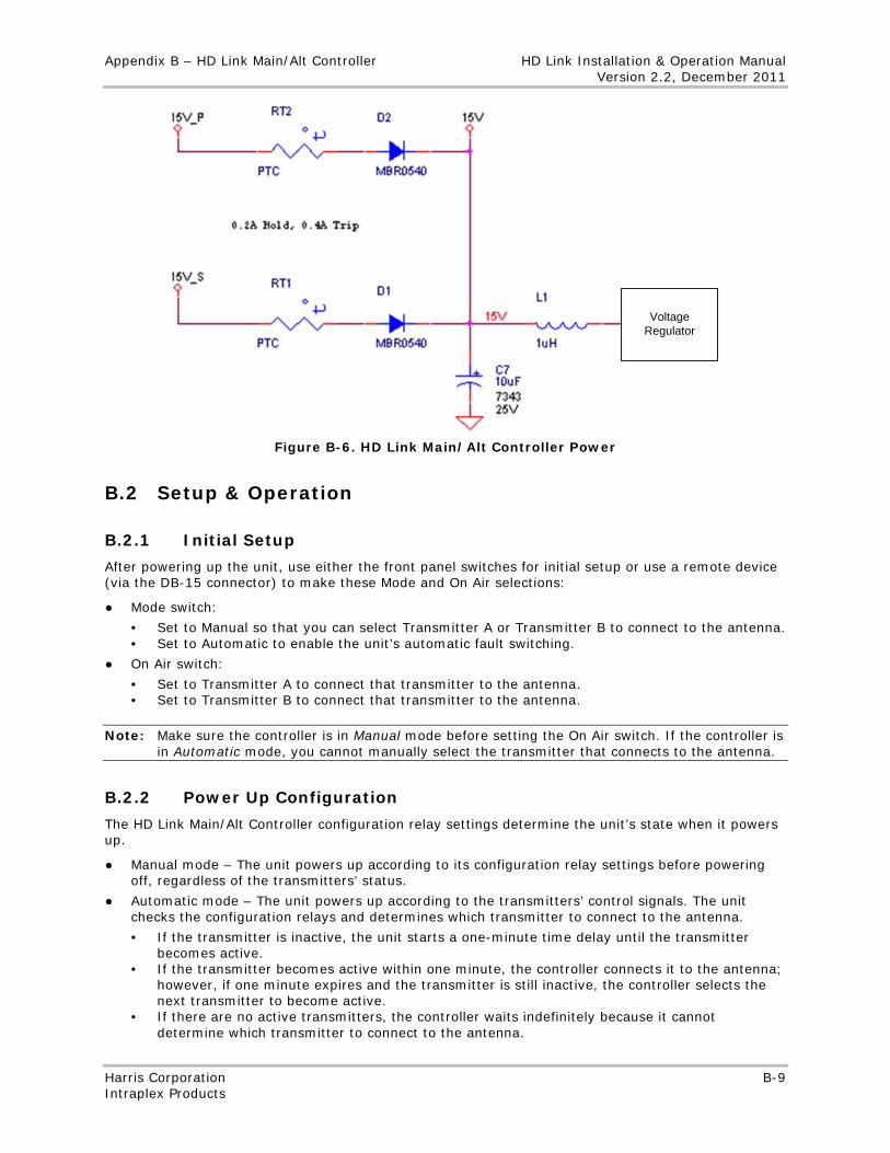
Appendix B – HD Link Main/Alt Controller HD Link Installation & Operation Manual Version 2.2, December 2011
Harris Corporation B-9 Intraplex Products
Voltage Regulator
Figure B-6. HD Link Main/Alt Controller Power
B.2 Setup & Operation
B.2.1 Initial Setup
After powering up the unit, use either the front panel switches for initial setup or use a remote device (via the DB-15 connector) to make these Mode and On Air selections:
● Mode switch:
• Set to Manual so that you can select Transmitter A or Transmitter B to connect to the antenna. • Set to Automatic to enable the unit’s automatic fault switching.
● On Air switch:
• Set to Transmitter A to connect that transmitter to the antenna. • Set to Transmitter B to connect that transmitter to the antenna.
Note: Make sure the controller is in Manual mode before setting the On Air switch. If the controller is in Automatic mode, you cannot manually select the transmitter that connects to the antenna.
B.2.2 Power Up Configuration
The HD Link Main/Alt Controller configuration relay settings determine the unit’s state when it powers up.
● Manual mode – The unit powers up according to its configuration relay settings before powering off, regardless of the transmitters’ status.
● Automatic mode – The unit powers up according to the transmitters’ control signals. The unit checks the configuration relays and determines which transmitter to connect to the antenna.
• If the transmitter is inactive, the unit starts a one-minute time delay until the transmitter becomes active.
• If the transmitter becomes active within one minute, the controller connects it to the antenna; however, if one minute expires and the transmitter is still inactive, the controller selects the next transmitter to become active.
• If there are no active transmitters, the controller waits indefinitely because it cannot determine which transmitter to connect to the antenna.
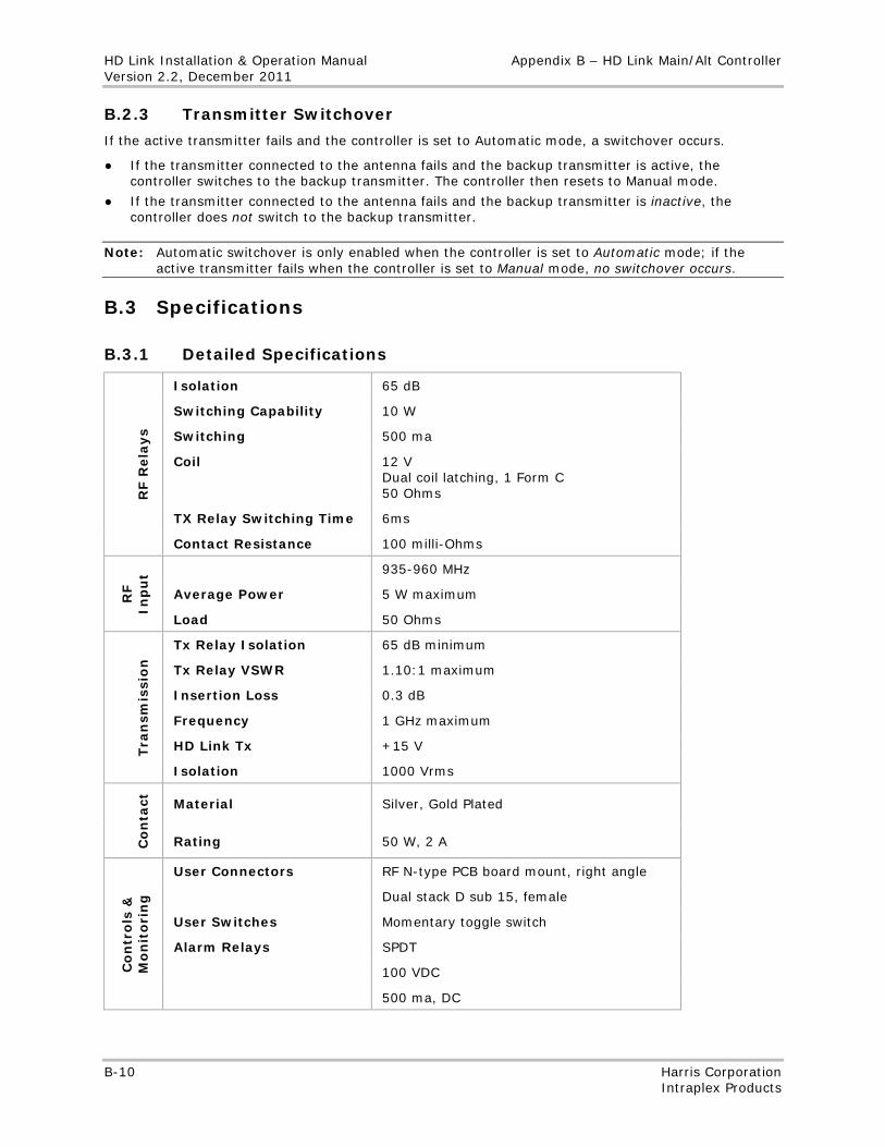
HD Link Installation & Operation Manual Appendix B – HD Link Main/Alt Controller Version 2.2, December 2011
B-10 Harris Corporation Intraplex Products
B.2.3 Transmitter Switchover
If the active transmitter fails and the controller is set to Automatic mode, a switchover occurs.
● If the transmitter connected to the antenna fails and the backup transmitter is active, the controller switches to the backup transmitter. The controller then resets to Manual mode.
● If the transmitter connected to the antenna fails and the backup transmitter is inactive, the controller does not switch to the backup transmitter.
Note: Automatic switchover is only enabled when the controller is set to Automatic mode; if the active transmitter fails when the controller is set to Manual mode, no switchover occurs.
B.3 Specifications
B.3.1 Detailed Specifications
RF R
ela
ys
Isolation 65 dB
Switching Capability 10 W
Switching 500 ma
Coil 12 V Dual coil latching, 1 Form C 50 Ohms
TX Relay Switching Time 6ms
Contact Resistance 100 milli-Ohms
RF
Inp
ut 935-960 MHz
Average Power 5 W maximum
Load 50 Ohms
Tra
nsm
issi
on
Tx Relay Isolation 65 dB minimum
Tx Relay VSWR 1.10:1 maximum
Insertion Loss 0.3 dB
Frequency 1 GHz maximum
HD Link Tx +15 V
Isolation 1000 Vrms
Co
nta
ct
Material Silver, Gold Plated
Rating 50 W, 2 A
Co
ntr
ols
&
Mo
nit
ori
ng
User Connectors RF N-type PCB board mount, right angle
Dual stack D sub 15, female
User Switches Momentary toggle switch
Alarm Relays SPDT
100 VDC
500 ma, DC
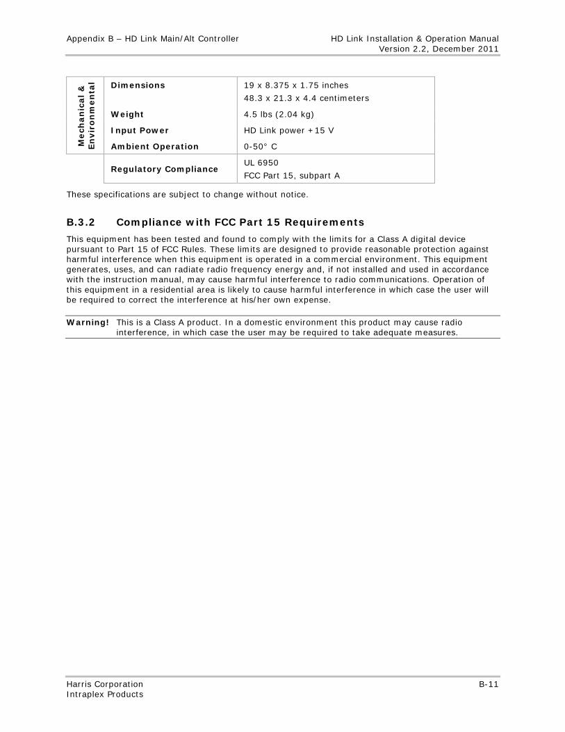
Appendix B – HD Link Main/Alt Controller HD Link Installation & Operation Manual Version 2.2, December 2011
Harris Corporation B-11 Intraplex Products
M
ech
an
ical
&
En
vir
on
men
tal Dimensions 19 x 8.375 x 1.75 inches
48.3 x 21.3 x 4.4 centimeters
Weight 4.5 lbs (2.04 kg)
Input Power HD Link power +15 V
Ambient Operation 0-50° C
Regulatory Compliance
UL 6950
FCC Part 15, subpart A
These specifications are subject to change without notice.
B.3.2 Compliance with FCC Part 15 Requirements
This equipment has been tested and found to comply with the limits for a Class A digital device pursuant to Part 15 of FCC Rules. These limits are designed to provide reasonable protection against harmful interference when this equipment is operated in a commercial environment. This equipment generates, uses, and can radiate radio frequency energy and, if not installed and used in accordance with the instruction manual, may cause harmful interference to radio communications. Operation of this equipment in a residential area is likely to cause harmful interference in which case the user will be required to correct the interference at his/her own expense.
Warning! This is a Class A product. In a domestic environment this product may cause radio interference, in which case the user may be required to take adequate measures.

No header
B-12 Harris Corporation Intraplex Products
This page is left blank intentionally.
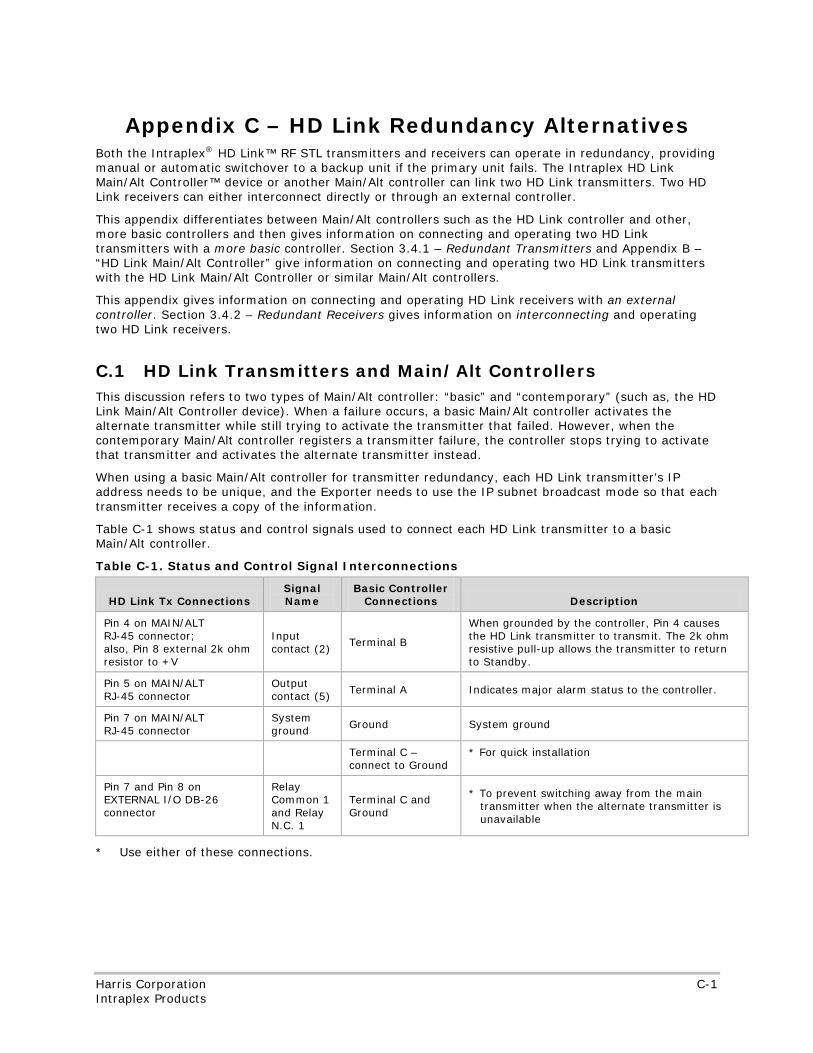
No header
Harris Corporation C-1 Intraplex Products
Appendix C – HD Link Redundancy Alternatives Both the Intraplex® HD Link™ RF STL transmitters and receivers can operate in redundancy, providing manual or automatic switchover to a backup unit if the primary unit fails. The Intraplex HD Link Main/Alt Controller™ device or another Main/Alt controller can link two HD Link transmitters. Two HD Link receivers can either interconnect directly or through an external controller.
This appendix differentiates between Main/Alt controllers such as the HD Link controller and other, more basic controllers and then gives information on connecting and operating two HD Link transmitters with a more basic controller. Section 3.4.1 – Redundant Transmitters and Appendix B – “HD Link Main/Alt Controller” give information on connecting and operating two HD Link transmitters with the HD Link Main/Alt Controller or similar Main/Alt controllers.
This appendix gives information on connecting and operating HD Link receivers with an external controller. Section 3.4.2 – Redundant Receivers gives information on interconnecting and operating two HD Link receivers.
C.1 HD Link Transmitters and Main/Alt Controllers This discussion refers to two types of Main/Alt controller: “basic” and “contemporary” (such as, the HD Link Main/Alt Controller device). When a failure occurs, a basic Main/Alt controller activates the alternate transmitter while still trying to activate the transmitter that failed. However, when the contemporary Main/Alt controller registers a transmitter failure, the controller stops trying to activate that transmitter and activates the alternate transmitter instead.
When using a basic Main/Alt controller for transmitter redundancy, each HD Link transmitter’s IP address needs to be unique, and the Exporter needs to use the IP subnet broadcast mode so that each transmitter receives a copy of the information.
Table C-1 shows status and control signals used to connect each HD Link transmitter to a basic Main/Alt controller.
Table C-1. Status and Control Signal Interconnections
HD Link Tx Connections Signal Name
Basic Controller Connections Description
Pin 4 on MAIN/ALT RJ-45 connector; also, Pin 8 external 2k ohm resistor to +V
Input contact (2)
Terminal B
When grounded by the controller, Pin 4 causes the HD Link transmitter to transmit. The 2k ohm resistive pull-up allows the transmitter to return to Standby.
Pin 5 on MAIN/ALT RJ-45 connector
Output contact (5)
Terminal A Indicates major alarm status to the controller.
Pin 7 on MAIN/ALT RJ-45 connector
System ground Ground System ground
Terminal C – connect to Ground
* For quick installation
Pin 7 and Pin 8 on EXTERNAL I/O DB-26 connector
Relay Common 1 and Relay N.C. 1
Terminal C and Ground
* To prevent switching away from the main transmitter when the alternate transmitter is unavailable
* Use either of these connections.
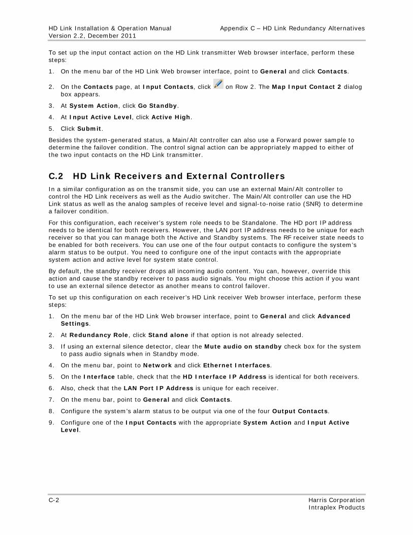
HD Link Installation & Operation Manual Appendix C – HD Link Redundancy Alternatives Version 2.2, December 2011
C-2 Harris Corporation Intraplex Products
To set up the input contact action on the HD Link transmitter Web browser interface, perform these steps:
1. On the menu bar of the HD Link Web browser interface, point to General and click Contacts.
2. On the Contacts page, at Input Contacts, click on Row 2. The Map Input Contact 2 dialog box appears.
3. At System Action, click Go Standby.
4. At Input Active Level, click Active High.
5. Click Submit.
Besides the system-generated status, a Main/Alt controller can also use a Forward power sample to determine the failover condition. The control signal action can be appropriately mapped to either of the two input contacts on the HD Link transmitter.
C.2 HD Link Receivers and External Controllers In a similar configuration as on the transmit side, you can use an external Main/Alt controller to control the HD Link receivers as well as the Audio switcher. The Main/Alt controller can use the HD Link status as well as the analog samples of receive level and signal-to-noise ratio (SNR) to determine a failover condition.
For this configuration, each receiver’s system role needs to be Standalone. The HD port IP address needs to be identical for both receivers. However, the LAN port IP address needs to be unique for each receiver so that you can manage both the Active and Standby systems. The RF receiver state needs to be enabled for both receivers. You can use one of the four output contacts to configure the system’s alarm status to be output. You need to configure one of the input contacts with the appropriate system action and active level for system state control.
By default, the standby receiver drops all incoming audio content. You can, however, override this action and cause the standby receiver to pass audio signals. You might choose this action if you want to use an external silence detector as another means to control failover.
To set up this configuration on each receiver’s HD Link receiver Web browser interface, perform these steps:
1. On the menu bar of the HD Link Web browser interface, point to General and click Advanced Settings.
2. At Redundancy Role, click Stand alone if that option is not already selected.
3. If using an external silence detector, clear the Mute audio on standby check box for the system to pass audio signals when in Standby mode.
4. On the menu bar, point to Network and click Ethernet Interfaces.
5. On the Interface table, check that the HD Interface IP Address is identical for both receivers.
6. Also, check that the LAN Port IP Address is unique for each receiver.
7. On the menu bar, point to General and click Contacts.
8. Configure the system’s alarm status to be output via one of the four Output Contacts.
9. Configure one of the Input Contacts with the appropriate System Action and Input Active Level.
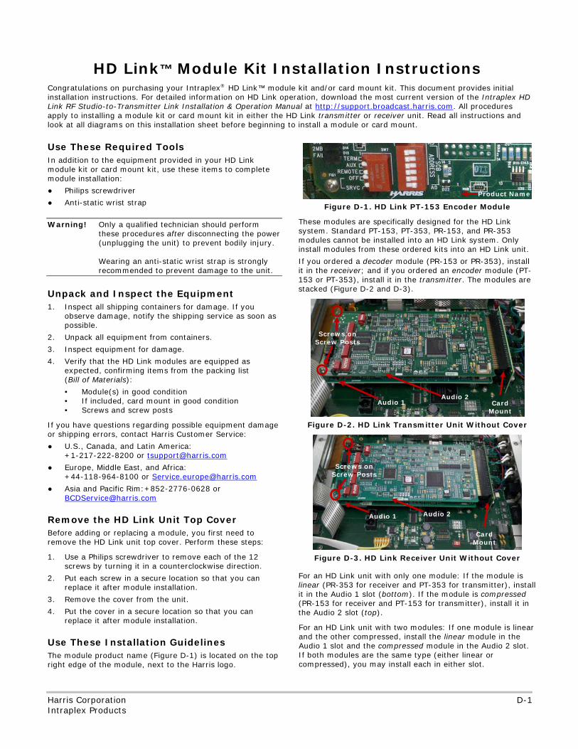
No header
Harris Corporation D-1 Intraplex Products
Congratulations on purchasing your Intraplex® HD Link™ module kit and/or card mount kit. This document provides initial installation instructions. For detailed information on HD Link operation, download the most current version of the Intraplex HD Link RF Studio-to-Transmitter Link Installation & Operation Manual at http://support.broadcast.harris.com. All procedures apply to installing a module kit or card mount kit in either the HD Link transmitter or receiver unit. Read all instructions and look at all diagrams on this installation sheet before beginning to install a module or card mount.
Use These Required Tools In addition to the equipment provided in your HD Link module kit or card mount kit, use these items to complete module installation:
● Philips screwdriver
● Anti-static wrist strap
Warning! Only a qualified technician should perform these procedures after disconnecting the power (unplugging the unit) to prevent bodily injury. Wearing an anti-static wrist strap is strongly recommended to prevent damage to the unit.
Unpack and Inspect the Equipment 1. Inspect all shipping containers for damage. If you
observe damage, notify the shipping service as soon as possible.
2. Unpack all equipment from containers.
3. Inspect equipment for damage.
4. Verify that the HD Link modules are equipped as expected, confirming items from the packing list (Bill of Materials):
• Module(s) in good condition • If included, card mount in good condition • Screws and screw posts
If you have questions regarding possible equipment damage or shipping errors, contact Harris Customer Service:
● U.S., Canada, and Latin America: +1-217-222-8200 or [email protected]
● Europe, Middle East, and Africa: +44-118-964-8100 or [email protected]
● Asia and Pacific Rim:+852-2776-0628 or [email protected]
Remove the HD Link Unit Top Cover Before adding or replacing a module, you first need to remove the HD Link unit top cover. Perform these steps:
1. Use a Philips screwdriver to remove each of the 12 screws by turning it in a counterclockwise direction.
2. Put each screw in a secure location so that you can replace it after module installation.
3. Remove the cover from the unit.
4. Put the cover in a secure location so that you can replace it after module installation.
Use These Installation Guidelines The module product name (Figure D-1) is located on the top right edge of the module, next to the Harris logo.
Figure D-1. HD Link PT-153 Encoder Module
These modules are specifically designed for the HD Link system. Standard PT-153, PT-353, PR-153, and PR-353 modules cannot be installed into an HD Link system. Only install modules from these ordered kits into an HD Link unit.
If you ordered a decoder module (PR-153 or PR-353), install it in the receiver; and if you ordered an encoder module (PT-153 or PT-353), install it in the transmitter. The modules are stacked (Figure D-2 and D-3).
Figure D-2. HD Link Transmitter Unit Without Cover
Figure D-3. HD Link Receiver Unit Without Cover
For an HD Link unit with only one module: If the module is linear (PR-353 for receiver and PT-353 for transmitter), install it in the Audio 1 slot (bottom). If the module is compressed (PR-153 for receiver and PT-153 for transmitter), install it in the Audio 2 slot (top).
For an HD Link unit with two modules: If one module is linear and the other compressed, install the linear module in the Audio 1 slot and the compressed module in the Audio 2 slot. If both modules are the same type (either linear or compressed), you may install each in either slot.
HD Link™ Module Kit Installation Instructions
Card Mount
Audio 1 Audio 2
Card Mount
Audio 1 Audio 2
Screws on Screw Posts
Product Name
Screws on Screw Posts
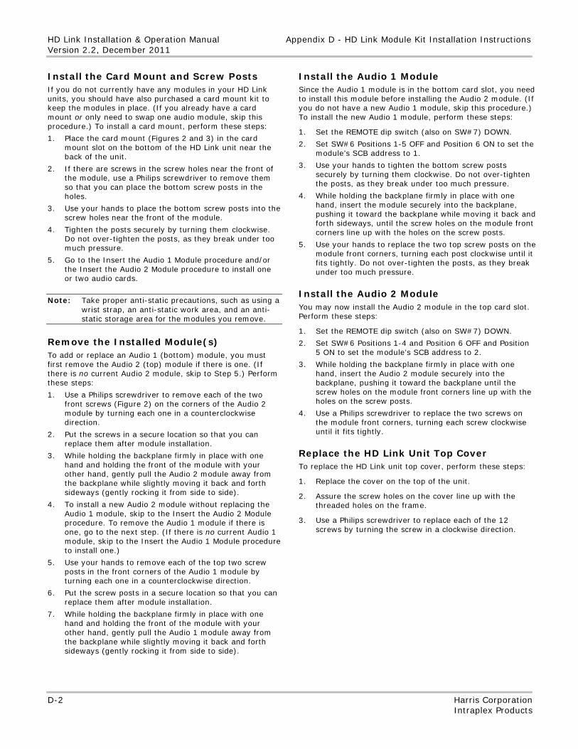
HD Link Installation & Operation Manual Appendix D - HD Link Module Kit Installation Instructions Version 2.2, December 2011
D-2 Harris Corporation Intraplex Products
Install the Card Mount and Screw Posts If you do not currently have any modules in your HD Link units, you should have also purchased a card mount kit to keep the modules in place. (If you already have a card mount or only need to swap one audio module, skip this procedure.) To install a card mount, perform these steps:
1. Place the card mount (Figures 2 and 3) in the card mount slot on the bottom of the HD Link unit near the back of the unit.
2. If there are screws in the screw holes near the front of the module, use a Philips screwdriver to remove them so that you can place the bottom screw posts in the holes.
3. Use your hands to place the bottom screw posts into the screw holes near the front of the module.
4. Tighten the posts securely by turning them clockwise. Do not over-tighten the posts, as they break under too much pressure.
5. Go to the Insert the Audio 1 Module procedure and/or the Insert the Audio 2 Module procedure to install one or two audio cards.
Note: Take proper anti-static precautions, such as using a wrist strap, an anti-static work area, and an anti-static storage area for the modules you remove.
Remove the Installed Module(s)
To add or replace an Audio 1 (bottom) module, you must first remove the Audio 2 (top) module if there is one. (If there is no current Audio 2 module, skip to Step 5.) Perform these steps: 1. Use a Philips screwdriver to remove each of the two
front screws (Figure 2) on the corners of the Audio 2 module by turning each one in a counterclockwise direction.
2. Put the screws in a secure location so that you can replace them after module installation.
3. While holding the backplane firmly in place with one hand and holding the front of the module with your other hand, gently pull the Audio 2 module away from the backplane while slightly moving it back and forth sideways (gently rocking it from side to side).
4. To install a new Audio 2 module without replacing the Audio 1 module, skip to the Insert the Audio 2 Module procedure. To remove the Audio 1 module if there is one, go to the next step. (If there is no current Audio 1 module, skip to the Insert the Audio 1 Module procedure to install one.)
5. Use your hands to remove each of the top two screw posts in the front corners of the Audio 1 module by turning each one in a counterclockwise direction.
6. Put the screw posts in a secure location so that you can replace them after module installation.
7. While holding the backplane firmly in place with one hand and holding the front of the module with your other hand, gently pull the Audio 1 module away from the backplane while slightly moving it back and forth sideways (gently rocking it from side to side).
Install the Audio 1 Module Since the Audio 1 module is in the bottom card slot, you need to install this module before installing the Audio 2 module. (If you do not have a new Audio 1 module, skip this procedure.) To install the new Audio 1 module, perform these steps:
1. Set the REMOTE dip switch (also on SW#7) DOWN.
2. Set SW#6 Positions 1-5 OFF and Position 6 ON to set the module’s SCB address to 1.
3. Use your hands to tighten the bottom screw posts securely by turning them clockwise. Do not over-tighten the posts, as they break under too much pressure.
4. While holding the backplane firmly in place with one hand, insert the module securely into the backplane, pushing it toward the backplane while moving it back and forth sideways, until the screw holes on the module front corners line up with the holes on the screw posts.
5. Use your hands to replace the two top screw posts on the module front corners, turning each post clockwise until it fits tightly. Do not over-tighten the posts, as they break under too much pressure.
Install the Audio 2 Module You may now install the Audio 2 module in the top card slot. Perform these steps:
1. Set the REMOTE dip switch (also on SW#7) DOWN.
2. Set SW#6 Positions 1-4 and Position 6 OFF and Position 5 ON to set the module’s SCB address to 2.
3. While holding the backplane firmly in place with one hand, insert the Audio 2 module securely into the backplane, pushing it toward the backplane until the screw holes on the module front corners line up with the holes on the screw posts.
4. Use a Philips screwdriver to replace the two screws on the module front corners, turning each screw clockwise until it fits tightly.
Replace the HD Link Unit Top Cover To replace the HD Link unit top cover, perform these steps:
1. Replace the cover on the top of the unit.
2. Assure the screw holes on the cover line up with the threaded holes on the frame.
3. Use a Philips screwdriver to replace each of the 12 screws by turning the screw in a clockwise direction.

No header here
No header
No footer
Broadcast Communications Division | Intraplex Products 5300 Kings Island Drive, Suite 101 | Mason, OH 45040
phone: 1 513 459 3400 | e-mail: [email protected] | www.broadcast.harris.com
Copyright © 2009-2011 Harris Corporation