Embed Size (px)
Citation preview

University of Texas at Austin CS354 - Computer Graphics Don Fussell
Intro to OpenGL
Don Fussell Computer Science Department
The University of Texas at Austin

Synthetic Camera Model
center of projection
image plane
projector
p
projection of p

Pinhole Camera
xp= -x/z/d yp= -y/z/d
Use similar triangles to find perspective projection of point at (x,y,z)
zp= d

Objects and Scenes
Programmers want to render “objects” Say a fire truck or molecule Arranged relative to other objects (a scene) & then viewed
Graphics pipeline approach—used by OpenGL and GPUs Break objects into geometry batches
Batches may be meshes or “patches” Batches reduce to polygonal primitives
Typically triangles But also lines, points, bitmaps, or images
Geometric primitives are specified by vertices So vertices are assembled into primitives
Primitives are rasterized into fragments Fragments are shaded Raster operations take shaded fragments and update the framebuffer

Advantages
Separation of objects, viewer, light sources Two-dimensional graphics is a special case of three-dimensional graphics Leads to simple software API
Specify objects, lights, camera, attributes Let implementation determine image
Leads to fast hardware implementation

CS 354
What is OpenGL? The OpenGL Graphics System
Not just for 3D graphics; imaging too “GL” standard for “Graphics Library” “Open” means industry standard meant for broad adoption with liberal licensing
Standardized in 1992 By Silicon Graphics And others: Compaq, DEC, Intel, IBM, Microsoft Originally meant for Unix and Windows workstations
Now de facto graphics acceleration standard Now managed by the Khronos industry consortium Available everywhere, from supercomputers to cell phones Alternative: Direct3D provides similar functionality with a very different API for Microsoft Windows platforms

Student’s View of OpenGL
You can learn OpenGL gradually Lots of its can be ignored for now The “classic” API is particularly nice “Deprecation” has ruined the pedagogical niceness of OpenGL; ignore deprecation
Plenty of documentation and sample code Makes concrete the abstract graphics pipeline for rasterization
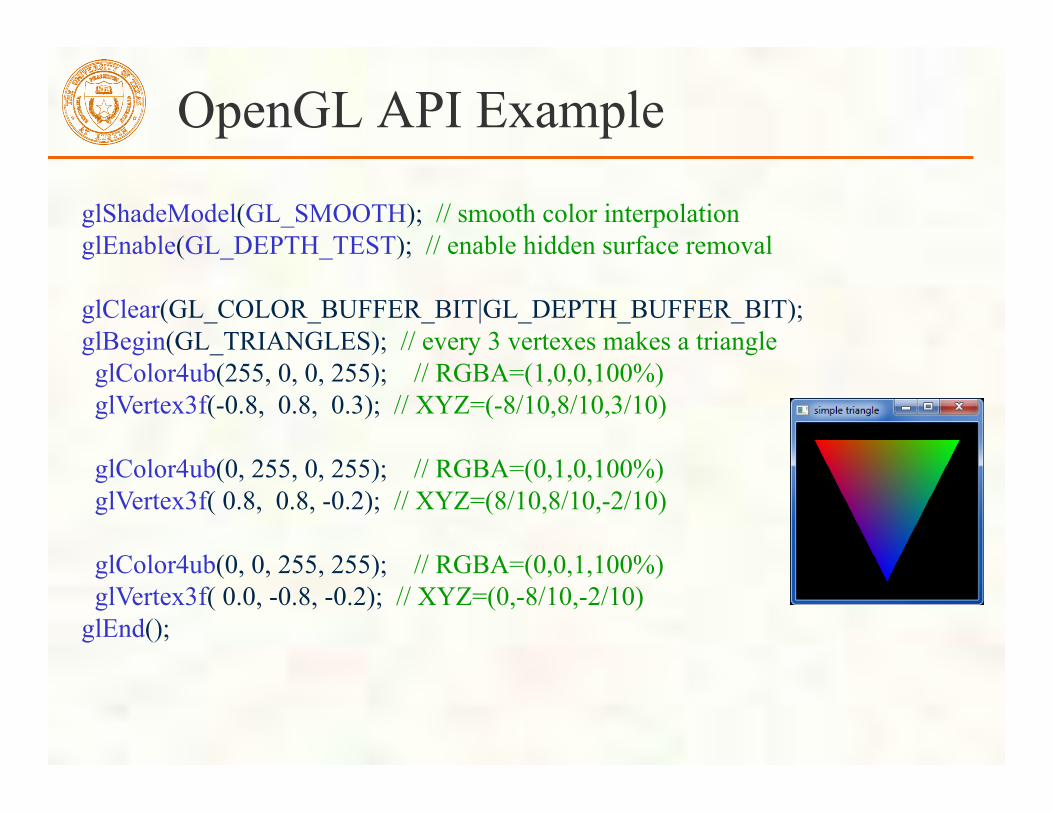
OpenGL API Example
glShadeModel(GL_SMOOTH); // smooth color interpolation glEnable(GL_DEPTH_TEST); // enable hidden surface removal glClear(GL_COLOR_BUFFER_BIT|GL_DEPTH_BUFFER_BIT); glBegin(GL_TRIANGLES); // every 3 vertexes makes a triangle glColor4ub(255, 0, 0, 255); // RGBA=(1,0,0,100%) glVertex3f(-0.8, 0.8, 0.3); // XYZ=(-8/10,8/10,3/10) glColor4ub(0, 255, 0, 255); // RGBA=(0,1,0,100%) glVertex3f( 0.8, 0.8, -0.2); // XYZ=(8/10,8/10,-2/10) glColor4ub(0, 0, 255, 255); // RGBA=(0,0,1,100%) glVertex3f( 0.0, -0.8, -0.2); // XYZ=(0,-8/10,-2/10) glEnd();

Initial Logical Coordinate System
Think of drawing into a [-1,+1]3 cube
(-0.8, 0.8) (-0.8, 0.8)
(0, -0.8)
origin at (0,0)

Normalized Device Coordinates What does this simple triangle look like with the [-1,+1]3 cube’s coordinate system?
We call this coordinate system “Normalize Device Coordinate” or NDC space
Wire frame cube shows boundaries of NDC space
From NDC views, you can see triangle isn’t “flat” in the Z direction Two vertices have Z of -0.2—third has Z of 0.3

GLUT API Example
#include <GL/glut.h> // includes necessary OpenGL headers void display() { // << insert code on prior slide here >> glutSwapBuffers(); } void main(int argc, char **argv) { // request double-buffered color window with depth buffer glutInitDisplayMode(GLUT_RGBA | GLUT_DOUBLE | GLUT_DEPTH); glutInit(&argc, argv); glutCreateWindow(“simple triangle”); glutDisplayFunc(display); // function to render window glutMainLoop(); }

CS 354
OpenGL Data Flow
vertex shading
rasterization & fragment
shading
texture raster
operations framebuffer
pixel unpack
pixel pack
vertex puller
client memory
pixel transfer
glReadPixels / glCopyPixels / glCopyTex{Sub}Image
glDrawPixels glBitmap glCopyPixels
glTex{Sub}Image glCopyTex{Sub}Image
glDrawElements glDrawArrays
selection / feedback / transform feedback
glVertex* glColor* glTexCoord* etc.
blending depth testing stencil testing accumulation
storage
operations

CS 354
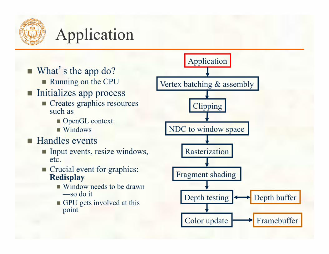
Simplified Graphics Pipeline Application
Vertex batching & assembly
Clipping
Rasterization
Fragment shading
Depth testing
Color update
OpenGL API
Framebuffer
NDC to window space
NDC = Normalized Device Coordinates, this is a [-1,+1]3 cube
Really lots more steps than this but these are the non-trivial operations in our simple triangle example
Depth buffer
Application
What’s the app do? Running on the CPU
Initializes app process Creates graphics resources such as
OpenGL context Windows
Handles events Input events, resize windows, etc. Crucial event for graphics: Redisplay
Window needs to be drawn—so do it GPU gets involved at this point
Application
Vertex batching & assembly
Clipping
Rasterization
Fragment shading
Depth testing
Color update Framebuffer
NDC to window space
Depth buffer
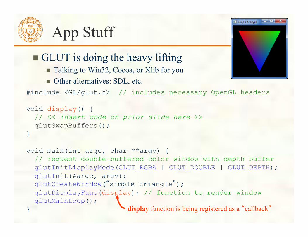
15 App Stuff
GLUT is doing the heavy lifting Talking to Win32, Cocoa, or Xlib for you Other alternatives: SDL, etc.
#include <GL/glut.h> // includes necessary OpenGL headers void display() { // << insert code on prior slide here >> glutSwapBuffers(); } void main(int argc, char **argv) { // request double-buffered color window with depth buffer glutInitDisplayMode(GLUT_RGBA | GLUT_DOUBLE | GLUT_DEPTH); glutInit(&argc, argv); glutCreateWindow(“simple triangle”); glutDisplayFunc(display); // function to render window glutMainLoop(); } display function is being registered as a “callback”

Rendering - the display Callback glShadeModel(GL_SMOOTH); // smooth color interpolation glEnable(GL_DEPTH_TEST); // enable hidden surface removal glClear(GL_COLOR_BUFFER_BIT|GL_DEPTH_BUFFER_BIT); glBegin(GL_TRIANGLES); { // every 3 vertexes makes a triangle glColor4ub(255, 0, 0, 255); // RGBA=(1,0,0,100%) glVertex3f(-0.8, 0.8, 0.3); // XYZ=(-8/10,8/10,3/10) glColor4ub(0, 255, 0, 255); // RGBA=(0,1,0,100%) glVertex3f( 0.8, 0.8, -0.2); // XYZ=(8/10,8/10,-2/10) glColor4ub(0, 0, 255, 255); // RGBA=(0,0,1,100%) glVertex3f( 0.0, -0.8, -0.2); // XYZ=(0,-8/10,-2/10) } glEnd();
Graphics state setting
Framebuffer buffer clearing
Triangle rendering

Graphics State Setting
Within the draw routine glShadeModel(GL_SMOOTH); // smooth color interpolation glEnable(GL_DEPTH_TEST); // enable hidden surface removal glClear(GL_COLOR_BUFFER_BIT|GL_DEPTH_BUFFER_BIT); glBegin(GL_TRIANGLES); { // every 3 vertexes makes a triangle glColor4ub(255, 0, 0, 255); // RGBA=(1,0,0,100%) glVertex3f(-0.8, 0.8, 0.3); // XYZ=(-8/10,8/10,3/10) glColor4ub(0, 255, 0, 255); // RGBA=(0,1,0,100%) glVertex3f( 0.8, 0.8, -0.2); // XYZ=(8/10,8/10,-2/10) glColor4ub(0, 0, 255, 255); // RGBA=(0,0,1,100%) glVertex3f( 0.0, -0.8, -0.2); // XYZ=(0,-8/10,-2/10) } glEnd(); graphics context state is “stateful” (sticky) so technically
doesn’t need to be done every time display is called
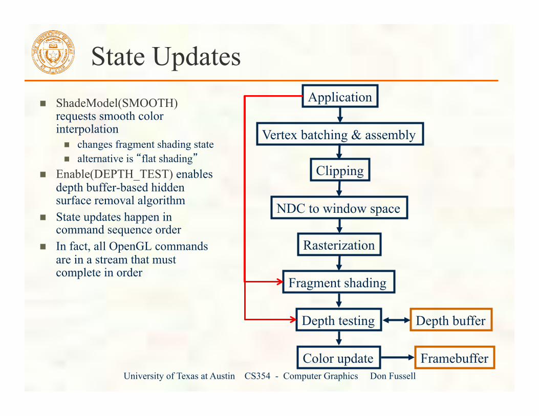
State Updates ShadeModel(SMOOTH) requests smooth color interpolation
changes fragment shading state alternative is “flat shading”
Enable(DEPTH_TEST) enables depth buffer-based hidden surface removal algorithm
State updates happen in command sequence order
In fact, all OpenGL commands are in a stream that must complete in order
Application
Vertex batching & assembly
Clipping
Rasterization
Fragment shading
Depth testing
Color update Framebuffer
NDC to window space
Depth buffer
University of Texas at Austin CS354 - Computer Graphics Don Fussell

19 Clearing the buffers
Within the draw routine glShadeModel(GL_SMOOTH); // smooth color interpolation glEnable(GL_DEPTH_TEST); // enable hidden surface removal glClear(GL_COLOR_BUFFER_BIT|GL_DEPTH_BUFFER_BIT); glBegin(GL_TRIANGLES); // every 3 vertexes makes a triangle glColor4ub(255, 0, 0, 255); // RGBA=(1,0,0,100%) glVertex3f(-0.8, 0.8, 0.3); // XYZ=(-8/10,8/10,3/10) glColor4ub(0, 255, 0, 255); // RGBA=(0,1,0,100%) glVertex3f( 0.8, 0.8, -0.2); // XYZ=(8/10,8/10,-2/10) glColor4ub(0, 0, 255, 255); // RGBA=(0,0,1,100%) glVertex3f( 0.0, -0.8, -0.2); // XYZ=(0,-8/10,-2/10) glEnd();

Buffer Clearing New frame needs to reset entire color buffer to “background” or “clear” color
Avoids having remnants of prior frame persist
Needed if can’t guarantee every pixel is touched every frame
Depth buffer needs to be cleared to “farthest value”
More about depth buffering later
Special operation in OpenGL Hardware wants clears to run at memory-saturating speeds Still in-band with command stream
Application
Vertex batching & assembly
Clipping
Rasterization
Fragment shading
Depth testing
Color update Framebuffer
NDC to window space
Depth buffer

Clear Values and Operations
OpenGL commands to set clear values glClearColor for RGBA color buffers
Example: glClearColor(0,0,0,1); Clear to black with 100% opacity Initial clear value is (0,0,0,0) so black with 0% opacity
glClearDepth for depth buffers Example: glClearDepth(1.0);
Clear to farthest depth value, for [0,1] range Initial depth clear value is 1.0 so farthest depth value
Neither commands does the actual clear operation… That’s done by glClear(mask)
Mask parameter indicates buffers to clear GL_COLOR_BUFFER_BIT, GL_DEPTH_BUFFER_BIT Bitwise-OR (|) them together Also GL_STENCIL_BUFFER_BIT, GL_ACCUM_BUFFER_BIT
Allows multiple buffers (e.g. depth & color) to be cleared in single operation, possibly in parallel

Batching and Assembling Vertices
glBegin and glEnd designate a batch of primitives
Begin mode of GL_TRIANGLES means every 3 vertexes = triangle
Various vertex attributes Position attribute sent with glVertex* commands Also colors, texture coordinates, normals, etc.
glVertex* assembles a vertex and puts it into the primitive batch
Other vertex attribute commands such as glColor* have their attributes “latched” when glVertex* assembles a vertex
Application
Vertex batching & assembly
Clipping
Rasterization
Fragment shading
Depth testing
Color update Framebuffer
NDC to window space
Depth buffer

Assembling a Vertex
R G B A
S T R Q
glColor4f
glColor3f glColor4ub, etc.
glTexCoord2f glTexCoord3s
glTexCoord4i, etc.
Nx Ny Nz glNormal3f glNormal3s
glNormal3b, etc.
glVertex2s glVertex3f glVertex4d
X Y Z W
Nx Ny Nz
S T R Q R G B A
X Y Z W assemble a vertex with all its attributes
to triangle
assembly
glVertex* command assembles a complete vertex
Vertex Attribute Commands
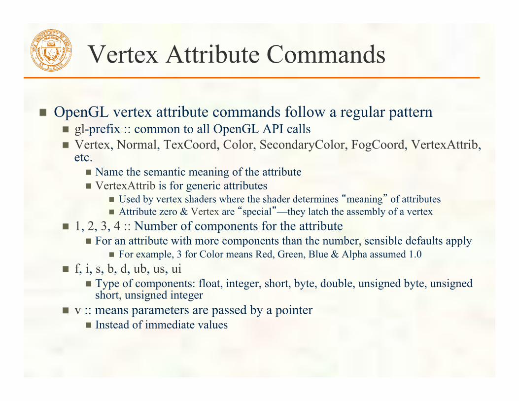
OpenGL vertex attribute commands follow a regular pattern gl-prefix :: common to all OpenGL API calls Vertex, Normal, TexCoord, Color, SecondaryColor, FogCoord, VertexAttrib, etc.
Name the semantic meaning of the attribute VertexAttrib is for generic attributes
Used by vertex shaders where the shader determines “meaning” of attributes Attribute zero & Vertex are “special”—they latch the assembly of a vertex
1, 2, 3, 4 :: Number of components for the attribute For an attribute with more components than the number, sensible defaults apply
For example, 3 for Color means Red, Green, Blue & Alpha assumed 1.0 f, i, s, b, d, ub, us, ui
Type of components: float, integer, short, byte, double, unsigned byte, unsigned short, unsigned integer
v :: means parameters are passed by a pointer Instead of immediate values

Example
Consider glColor4ub and glVertex3fv
glColor4ub(red, green, blue, alpha);
glVertex3fv(const GLfloat v[3]);
Belongs to OpenGL
Meaning of attribute
Number of components
Type of components
Vector arguments

Assemble a Triangle
Within the draw routine glBegin(GL_TRIANGLES); glColor4ub(255, 0, 0, 255); glVertex3f(-0.8, 0.8, 0.3); glColor4ub(0, 255, 0, 255); glVertex3f( 0.8, 0.8, -0.2); glColor4ub(0, 0, 255, 255); glVertex3f( 0.0, -0.8, -0.2); glEnd();
First vertex
Second vertex
Third vertex
First triangle

glBegin Primitive Batch Types

Assembly State Machines
Fixed-function hardware performs primitive assembly Based on glBegin’s mode
State machine for GL_TRIANGLES
initial
no vertex
one vertex
two vertexes
Begin(TRIANGLES) Vertex Vertex Vertex /
Emit Triangle
End End End

GL_TRIANGLE_STRIP
initial
no vertex
one vertex
two vertexes
Begin(TRIANGLE_ STRIP)
Vertex Vertex Vertex / Emit Triangle
End End End
two vertexes
Vertex / Emit Reverse
Triangle
End

CS 354
GL_POINTS and GL_LINES
initial
no vertex
one vertex
Begin(LINES)
Vertex / Emit Line
End End
initial
no vertex
Begin(POINTS)
Vertex / Emit Point
End
Actual hardware state machine handles all OpenGL begin modes, so rather complex

CS 354
Triangle Assembly
Now we have a triangle assembled Later, we’ll generalize how the vertex positions get transformed
And other attributes might be processed too
For now, just assume the XYZ position passed to glVertex3f position is in NDC space
Application
Vertex batching & assembly
Clipping
Rasterization
Fragment shading
Depth testing
Color update Framebuffer
NDC to window space
Depth buffer

Our Newly Assembled Triangle
Think of drawing into a [-1,+1]3 cube (-1.8, 0.8, 0.3) (-0.8, 0.8, -0.2)
(0, -0.8, -0.2)
origin at (0,0,0)
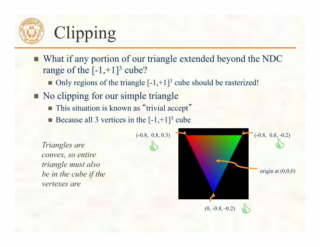
Clipping What if any portion of our triangle extended beyond the NDC range of the [-1,+1]3 cube?
Only regions of the triangle [-1,+1]3 cube should be rasterized!
No clipping for our simple triangle This situation is known as “trivial accept” Because all 3 vertices in the [-1,+1]3 cube
(-0.8, 0.8, 0.3) (-0.8, 0.8, -0.2)
(0, -0.8, -0.2)
origin at (0,0,0)
! !
!
Triangles are convex, so entire triangle must also be in the cube if the vertexes are
Triangle Clipping
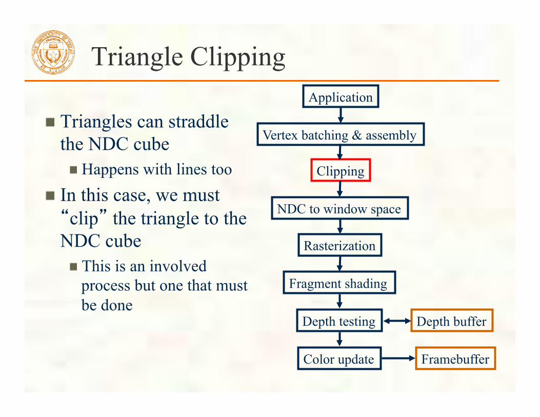
Triangles can straddle the NDC cube
Happens with lines too In this case, we must “clip” the triangle to the NDC cube
This is an involved process but one that must be done
Application
Vertex batching & assembly
Clipping
Rasterization
Fragment shading
Depth testing
Color update Framebuffer
NDC to window space
Depth buffer

Consider a Different Triangle Move left vertex so it’s X = -1.8
Result is a clipped triangle
(-1.8, 0.8, 0.3)
(-0.8, 0.8, -0.2)
(0, -0.8, -0.2)
origin at (0,0,0) "
!
!

Clipped Triangle Visualized
Clipped and Rasterized Normally Visualization of NDC space
Notice triangle is “poking out” of the cube; this is the reason that should be clipped

New triangles out
But how do we find these “new” vertices? The edge clipping the triangle is the line at X = -1
so we know X = -1 at these points—but what about Y?

CS 354
Use Ratios to Interpolate Clipped Positions
(-1.8, 0.8, 0.3)
(-0.8, 0.8, -0.2)
(0, -0.8, -0.2)
origin at (0,0,0)
X = -1 Y = (1.8/2.6)×0.8 + (0.8/2.6)×0.8 = 0.8 Z = (1.8/2.6)×0.3 + (0.8/2.6)×-0.2 = 0.1461538
-1-(-1.8)=0.8
0.8-(-1)=1.8
0.8-(-1.8)=2.6 (-1,0.8,0.146153)
Straightforward because all the edges are orthogonal
Weights: 1.8/2.6 0.8/2.6, sum to 1

Use Ratios to Interpolate Clipped Positions
(-1.8, 0.8, 0.3)
(-0.8, 0.8, -0.2)
(0, -0.8, -0.2)
origin at (0,0,0)
0-(-1.8) = 1.8
0-(-1) = 1
X = -1 Y = (1/1.8)×0.8 + (0.8/1.8)×-0.8 = 0.08888… Z = (1/1.8)×0.3 + (0.8/1.8)×-0.2 = 0.07777…
(-1,0.0888,0.0777)
-1-(-1.8) = 0.8
Weights: 1/1.8 0.8/1.8, sum to 1

Clipping Complications
Given primitive may be clipped by multiple cube faces Potentially clipping by all 6 faces!
Approach Four possibilities
Face doesn’t actually result in any clipping of a triangle Triangle is unaffected by this plane then
Clipping eliminates a triangle completely All 3 vertices on “wrong” side of the face’s plane
Triangle “tip” clipped away Leaving two triangles
Triangle “base” is clipped away Leaving a single triangle
Strategy: implement recursive clipping process “Two triangle” case means resulting two triangles must be clipped by all remaining planes

Attribute Interpolation
When splitting triangles for clipping, must also interpolate new attributes
For example, color Also texture coordinates
Back to our example BLUE×0.8/1.8 + RED×1/1.8
(0,0,1,1)×0.8/1.8 + (1,0,0,1)×1/1.8 (0.444,0,.555,1) or MAGENTA
Weights: 1/1.8 0.8/1.8, sum to 1
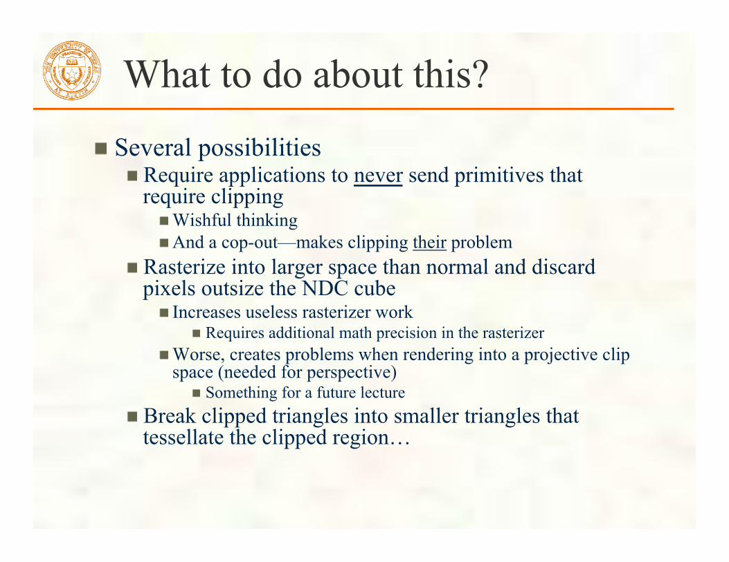
What to do about this?
Several possibilities Require applications to never send primitives that require clipping
Wishful thinking And a cop-out—makes clipping their problem
Rasterize into larger space than normal and discard pixels outsize the NDC cube
Increases useless rasterizer work Requires additional math precision in the rasterizer
Worse, creates problems when rendering into a projective clip space (needed for perspective)
Something for a future lecture Break clipped triangles into smaller triangles that tessellate the clipped region…

Triangle clipped by Two Planes
Recursive process can make 4 triangles And it gets worse with more non-trivial clipping

NDC to Window Space
NDC is “normalized” to the [-1,+1]3 cube
Nice for clipping But doesn’t yet map to pixels on the screen
Next: a transform from NDC space to window space
Application
Vertex batching & assembly
Clipping
Rasterization
Fragment shading
Depth testing
Color update Framebuffer
NDC to window space
Depth buffer

Viewport and Depth Range
OpenGL has 2 commands to configure the state to map NDC space to window space
glViewport(GLint vx, GLint vy, GLsizei w, GLsizei h); Typically programmed to the window’s width and height for w & h and zero for both vx & vy Example: glViewport(0, 0, window_width, window_height);
glDepthRange(GLclampd n, GLclampd f); n for near depth value, f for far depth value Normally set to glDepthRange(0,1)
Which is an OpenGL context’s initial depth range state
The mapping from NDC space to window space depends on vx, vy, w, h, n, and d

OpenGL Data Type Naming
The OpenGL specification allow an implementation to specify how language data types map to OpenGL API data types
GLfloat is usually typedef’ed to float but this isn’t necessarily true Same for GLint, GLshort, GLdouble But is true in practice
GLbyte is byte-sized so expected it to be a char GLubyte, GLushort, and GLuint are unsigned versions of GLbyte, GLshort, and GLint
Certain names clue you into their parameter usage GLsizei is an integer parameter that is not allowed to be negative
An GL_INVALID_VALUE is generated if a GLsizei parameter is ever negative
GLclampd and GLclampf are the same as GLfloat and GLdouble, but indicate the parameter will be clamped automatically to the [0,1] range
Notice glViewport uses GLsizei for width and height glDepthRange uses GLclampd for near and far

OpenGL Errors
OpenGL reports asynchronously from your commands Effectively, you must explicitly call glGetError to find if any prior command generated an error or was otherwise used incorrectly glGetError returns GL_NO_ERROR if there is no error
Otherwise an error such as GL_INVALID_VALUE is returned Rationale
OpenGL commands are meant to be executed in a pipeline so the error might not be identified until after the command’s function has returned
Errors might be detected by hardware that isn’t actually the CPU Also forcing applications to check return codes of functions is slow
It’s inappropriate for a high-performance API such as OpenGL So if you suspect errors, you have to poll for them
Learn to do this while you are debugging your code If something fails to happen, suspect there’s an OpenGL errors
Also commands that generated an error are ignored The only exception is GL_OUT_OF_MEMORY which results in undefined state

Mapping NDC to Window Space
Assume (x,y,z) is the NDC coordinate that’s passed to glVertex3f in our simple_triangle example Then window-space (wx,wy,wz) location is
wx = (w/2)×x + vx + w/2
wy = (h/2)×y + vy + h/2
wz = [(f-n)/2]×z + (n+f)/2
× means scalar multiplication here

Where is glViewport set? The simple_triangle program never calls glViewport
That’s OK because GLUT will call glViewport for you if you don’t register your own per-window callback to handle when a window is reshaped (resized) Without a reshape callback registered, GLUT will simply call glViewport(0, 0, window_width, window_height);
Alternatively, you can use glReshapeFunc to register a callback
Then calling glViewport or otherwise tracking the window height becomes your application’s responsibility Example reshape callback: void reshape(int w, int h) { glViewport(0, 0, w, h); } Example registering a reshape callback: glReshapeFunc(reshape);
FYI: OpenGL maintains a lower-left window-space origin Whereas most 2D graphics APIs use upper-left

What about glDepthRange?
Simple applications don’t normally need to call glDepthRange
Notice the simple_triangle program never calls glDepthRange
Rationale The initial depth range of [0,1] is fine for most application It says the entire available depth buffer range should be used
When the depth range is [0,1] the equation for window-space z simplifies to wz = ½×z + ½
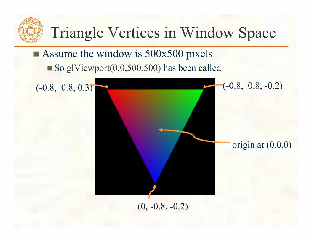
Triangle Vertices in Window Space Assume the window is 500x500 pixels
So glViewport(0,0,500,500) has been called
(-0.8, 0.8, 0.3) (-0.8, 0.8, -0.2)
(0, -0.8, -0.2)
origin at (0,0,0)
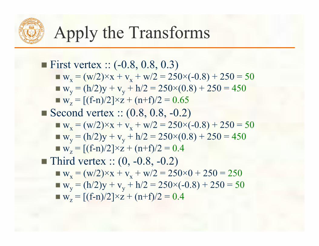
Apply the Transforms
First vertex :: (-0.8, 0.8, 0.3) wx = (w/2)×x + vx + w/2 = 250×(-0.8) + 250 = 50 wy = (h/2)y + vy + h/2 = 250×(0.8) + 250 = 450 wz = [(f-n)/2]×z + (n+f)/2 = 0.65
Second vertex :: (0.8, 0.8, -0.2) wx = (w/2)×x + vx + w/2 = 250×(-0.8) + 250 = 50 wy = (h/2)y + vy + h/2 = 250×(0.8) + 250 = 450 wz = [(f-n)/2]×z + (n+f)/2 = 0.4
Third vertex :: (0, -0.8, -0.2) wx = (w/2)×x + vx + w/2 = 250×0 + 250 = 250 wy = (h/2)y + vy + h/2 = 250×(-0.8) + 250 = 50 wz = [(f-n)/2]×z + (n+f)/2 = 0.4

Still Left to Do
Rasterize the clipped triangle But our triangle’s vertexes are in window space so we are ready
Interpolate color values over the triangle Depth test the triangle Update pixel locations Swap buffers Next lecture!

Next Lecture Graphics Pipeline
What are the operations in the so-called “graphics pipeline”? As usual, expect a short quiz on today’s lecture
Know how to map clip space to NDC space to window space
Assignments Reading from “Interactive Computer Graphics” (Angel)
Chapter 2, pages 43-107 Homework (a.k.a. Project Zero), deadline January 25th
Get the ZIP for the “simple triangle” and “clip space” example programs Learn how to compile and run them on your CS account Modify either program to
Change the clear color to burnt orange Change the title of the window to your name Instead of drawing a single triangle, make a simple arrangement of polygons
forming a letter from your name Use the turnin system to submit your modified source code and a screenshot image of your modified example Purpose
Gain familiarity with OpenGL programming and submitting projects

Programming tips 3D graphics, whether OpenGL or Direct3D or any other API, can be frustrating
You write a bunch of code and the result is
Nothing but black window; where did your rendering go??

Things to Try Set your clear color to something other than black!
It is easy to draw things black accidentally so don’t make black the clear color But black is the initial clear color
Did you draw something for one frame, but the next frame draws nothing? Are you using depth buffering? Did you forget to clear the depth buffer?
Remember there are near and far clip planes so clipping in Z, not just X & Y Have you checked for glGetError?
Call glGetError once per frame while debugging so you can see errors that occur For release code, take out the glGetError calls
Not sure what state you are in? Use glGetIntegerv or glGetFloatv or other query functions to make sure that OpenGL’s state is what you think it is
Use glutSwapBuffers to flush your rendering and show to the visible window Likewise glFinish makes sure all pending commands have finished
Try reading http://www.slideshare.net/Mark_Kilgard/avoiding-19-common-opengl-pitfalls This is well worth the time wasted debugging a problem that could be avoided