Embed Size (px)
Citation preview
Chapter 1
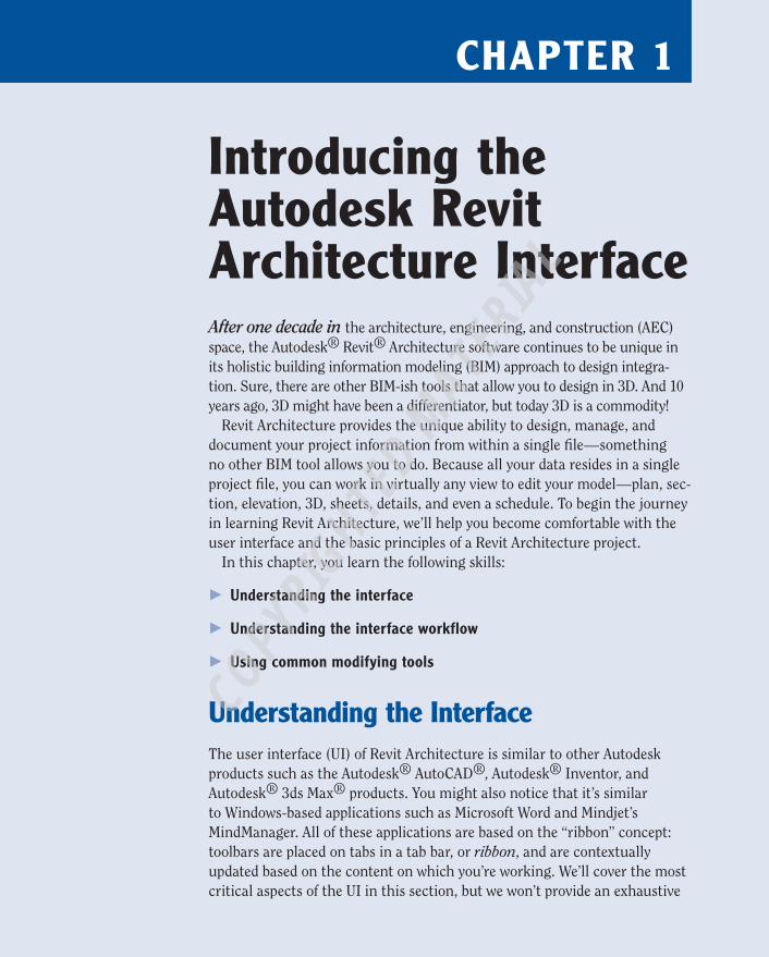
Introducing the autodesk revit architecture InterfaceAfter one decade in the architecture, engineering, and construction (AEC) space, the Autodesk® Revit® Architecture software continues to be unique in its holistic building information modeling (BIM) approach to design integra-tion. Sure, there are other BIM-ish tools that allow you to design in 3D. And 10 years ago, 3D might have been a differentiator, but today 3D is a commodity!
Revit Architecture provides the unique ability to design, manage, and document your project information from within a single file—something no other BIM tool allows you to do. Because all your data resides in a single project file, you can work in virtually any view to edit your model—plan, sec-tion, elevation, 3D, sheets, details, and even a schedule. To begin the journey in learning Revit Architecture, we’ll help you become comfortable with the user interface and the basic principles of a Revit Architecture project.
In this chapter, you learn the following skills:
�� Understanding the interface
�� Understanding the interface workflow
�� Using common modifying tools
Understanding the InterfaceThe user interface (UI) of Revit Architecture is similar to other Autodesk products such as the Autodesk® AutoCAD®, Autodesk® Inventor, and Autodesk® 3ds Max® products. You might also notice that it’s similar to Windows-based applications such as Microsoft Word and Mindjet’s MindManager. All of these applications are based on the “ribbon” concept: toolbars are placed on tabs in a tab bar, or ribbon, and are contextually updated based on the content on which you’re working. We’ll cover the most critical aspects of the UI in this section, but we won’t provide an exhaustive
244784c01.indd 1 3/16/12 10:44 AM
COPYRIG
HTED M
ATERIAL

2 C h a p t e r 1 • I n t r o d u c i n g t h e A u t o d e s k R e v i t A r c h i t e c t u r e I n t e r f a c e
review of all toolbars and commands. You’ll gain experience with the common tools as you read the chapters and exercises in this book.
Figure 1.1 shows the Revit Architecture UI. To illustrate some different project views, we’ve tiled four different view windows: Plan, Elevation, 3D, and Camera.
Application Button
Tab Quick Access ToolbarTool
Contextual Tab InfoCenter
Ribbon
Options BarPanel
Properties Palette
Project Browser
Status Bar View Control Bar Drawing Areas
F I g U r e 1 . 1 : Revit Architecture user interface
Let’s begin by examining a few important parts of the UI. As you progress through this book, you’ll gradually become more familiar with the other basic parts of the UI.
properties paletteThe Properties palette is a floating palette that can remain open while you work in the model. The palette can be docked on either side of your screen, or it can be moved to a second monitor. You can open the Properties palette in one of three ways:
�� Click the Properties icon in the Properties panel of the Modify tab in the ribbon.
�� Select Properties from the right-click context menu.
�� Press Ctrl+1 on your keyboard, as you would in AutoCAD.
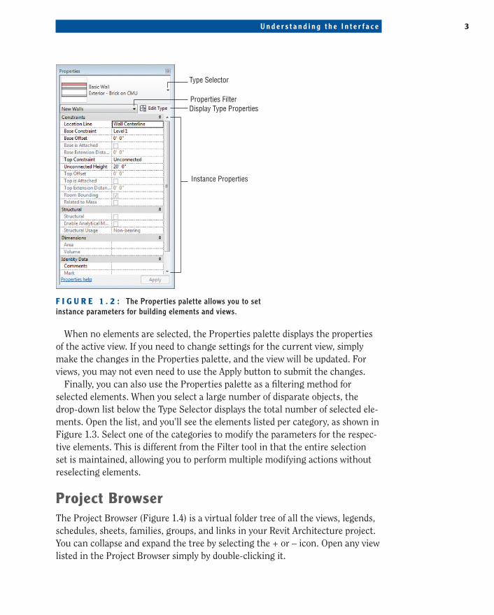
As shown in Figure 1.2, the Properties palette contains the Type Selector at the top of the palette. When you’re placing elements or swapping types of ele-ments you’ve already placed in the model, the palette must be open to access the Type Selector.
244784c01.indd 2 3/16/12 10:44 AM
U n d e r s t a n d i n g t h e I n t e r f a c e 3
Type Selector
Properties FilterDisplay Type Properties
Instance Properties
F I g U r e 1 . 2 : The Properties palette allows you to set instance parameters for building elements and views.
When no elements are selected, the Properties palette displays the properties of the active view. If you need to change settings for the current view, simply make the changes in the Properties palette, and the view will be updated. For views, you may not even need to use the Apply button to submit the changes.
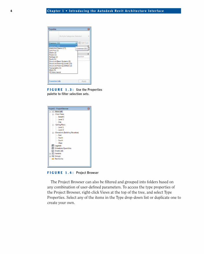
Finally, you can also use the Properties palette as a filtering method for selected elements. When you select a large number of disparate objects, the drop-down list below the Type Selector displays the total number of selected ele-ments. Open the list, and you’ll see the elements listed per category, as shown in Figure 1.3. Select one of the categories to modify the parameters for the respec-tive elements. This is different from the Filter tool in that the entire selection set is maintained, allowing you to perform multiple modifying actions without reselecting elements.
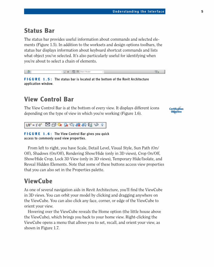
project BrowserThe Project Browser (Figure 1.4) is a virtual folder tree of all the views, legends, schedules, sheets, families, groups, and links in your Revit Architecture project. You can collapse and expand the tree by selecting the + or – icon. Open any view listed in the Project Browser simply by double-clicking it.
244784c01.indd 3 3/16/12 10:44 AM
4 C h a p t e r 1 • I n t r o d u c i n g t h e A u t o d e s k R e v i t A r c h i t e c t u r e I n t e r f a c e
F I g U r e 1 . 3 : Use the Properties palette to filter selection sets.
F I g U r e 1 . 4 : Project Browser
The Project Browser can also be filtered and grouped into folders based on any combination of user-defined parameters. To access the type properties of the Project Browser, right-click Views at the top of the tree, and select Type Properties. Select any of the items in the Type drop-down list or duplicate one to create your own.
244784c01.indd 4 3/16/12 10:44 AM
U n d e r s t a n d i n g t h e I n t e r f a c e 5
Status BarThe status bar provides useful information about commands and selected ele-ments (Figure 1.5). In addition to the worksets and design options toolbars, the status bar displays information about keyboard shortcut commands and lists what object you’ve selected. It’s also particularly useful for identifying when you’re about to select a chain of elements.
F I g U r e 1 . 5 : The status bar is located at the bottom of the Revit Architecture application window.
View Control BarThe View Control Bar is at the bottom of every view. It displays different icons depending on the type of view in which you’re working (Figure 1.6).
F I g U r e 1 . 6 : The View Control Bar gives you quick access to commonly used view properties.
From left to right, you have Scale, Detail Level, Visual Style, Sun Path (On/Off), Shadows (On/Off), Rendering Show/Hide (only in 3D views), Crop On/Off, Show/Hide Crop, Lock 3D View (only in 3D views), Temporary Hide/Isolate, and Reveal Hidden Elements. Note that some of these buttons access view properties that you can also set in the Properties palette.
ViewCubeAs one of several navigation aids in Revit Architecture, you’ll find the ViewCube in 3D views. You can orbit your model by clicking and dragging anywhere on the ViewCube. You can also click any face, corner, or edge of the ViewCube to orient your view.
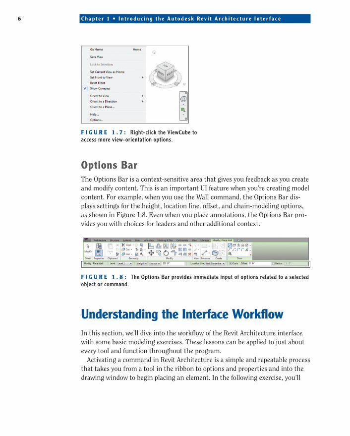
Hovering over the ViewCube reveals the Home option (the little house above the ViewCube), which brings you back to your home view. Right-clicking the ViewCube opens a menu that allows you to set, recall, and orient your view, as shown in Figure 1.7.
CertificationObjective
244784c01.indd 5 3/16/12 10:44 AM
6 C h a p t e r 1 • I n t r o d u c i n g t h e A u t o d e s k R e v i t A r c h i t e c t u r e I n t e r f a c e
F I g U r e 1 . 7 : Right-click the ViewCube to access more view-orientation options.
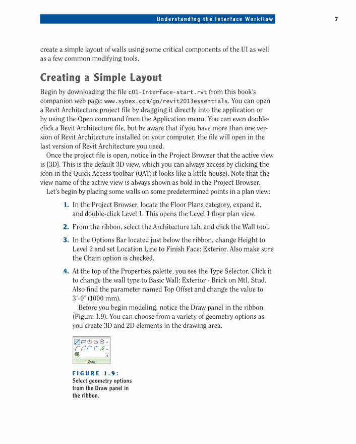
Options BarThe Options Bar is a context-sensitive area that gives you feedback as you create and modify content. This is an important UI feature when you’re creating model content. For example, when you use the Wall command, the Options Bar dis-plays settings for the height, location line, offset, and chain-modeling options, as shown in Figure 1.8. Even when you place annotations, the Options Bar pro-vides you with choices for leaders and other additional context.
F I g U r e 1 . 8 : The Options Bar provides immediate input of options related to a selected object or command.
Understanding the Interface WorkflowIn this section, we’ll dive into the workflow of the Revit Architecture interface with some basic modeling exercises. These lessons can be applied to just about every tool and function throughout the program.
Activating a command in Revit Architecture is a simple and repeatable process that takes you from a tool in the ribbon to options and properties and into the drawing window to begin placing an element. In the following exercise, you’ll
244784c01.indd 6 3/16/12 10:44 AM
U n d e r s t a n d i n g t h e I n t e r f a c e Wo r k f l o w 7
create a simple layout of walls using some critical components of the UI as well as a few common modifying tools.
Creating a Simple LayoutBegin by downloading the file c01-Interface-start.rvt from this book’s companion web page: www.sybex.com/go/revit2013essentials. You can open a Revit Architecture project file by dragging it directly into the application or by using the Open command from the Application menu. You can even double-click a Revit Architecture file, but be aware that if you have more than one ver-sion of Revit Architecture installed on your computer, the file will open in the last version of Revit Architecture you used.
Once the project file is open, notice in the Project Browser that the active view is {3D}. This is the default 3D view, which you can always access by clicking the icon in the Quick Access toolbar (QAT; it looks like a little house). Note that the view name of the active view is always shown as bold in the Project Browser.
Let’s begin by placing some walls on some predetermined points in a plan view:
1. In the Project Browser, locate the Floor Plans category, expand it, and double-click Level 1. This opens the Level 1 floor plan view.
2. From the ribbon, select the Architecture tab, and click the Wall tool.
3. In the Options Bar located just below the ribbon, change Height to Level 2 and set Location Line to Finish Face: Exterior. Also make sure the Chain option is checked.
4. At the top of the Properties palette, you see the Type Selector. Click it to change the wall type to Basic Wall: Exterior - Brick on Mtl. Stud. Also find the parameter named Top Offset and change the value to 3´-0˝ (1000 mm).
Before you begin modeling, notice the Draw panel in the ribbon (Figure 1.9). You can choose from a variety of geometry options as you create 3D and 2D elements in the drawing area.
F I g U r e 1 . 9 : Select geometry options from the Draw panel in the ribbon.
244784c01.indd 7 3/16/12 10:44 AM
8 C h a p t e r 1 • I n t r o d u c i n g t h e A u t o d e s k R e v i t A r c h i t e c t u r e I n t e r f a c e
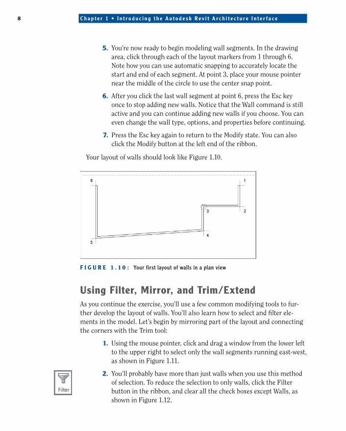
5. You’re now ready to begin modeling wall segments. In the drawing area, click through each of the layout markers from 1 through 6. Note how you can use automatic snapping to accurately locate the start and end of each segment. At point 3, place your mouse pointer near the middle of the circle to use the center snap point.
6. After you click the last wall segment at point 6, press the Esc key once to stop adding new walls. Notice that the Wall command is still active and you can continue adding new walls if you choose. You can even change the wall type, options, and properties before continuing.
7. Press the Esc key again to return to the Modify state. You can also click the Modify button at the left end of the ribbon.
Your layout of walls should look like Figure 1.10.
F I g U r e 1 . 1 0 : Your first layout of walls in a plan view
Using Filter, Mirror, and trim/extendAs you continue the exercise, you’ll use a few common modifying tools to fur-ther develop the layout of walls. You’ll also learn how to select and filter ele-ments in the model. Let’s begin by mirroring part of the layout and connecting the corners with the Trim tool:
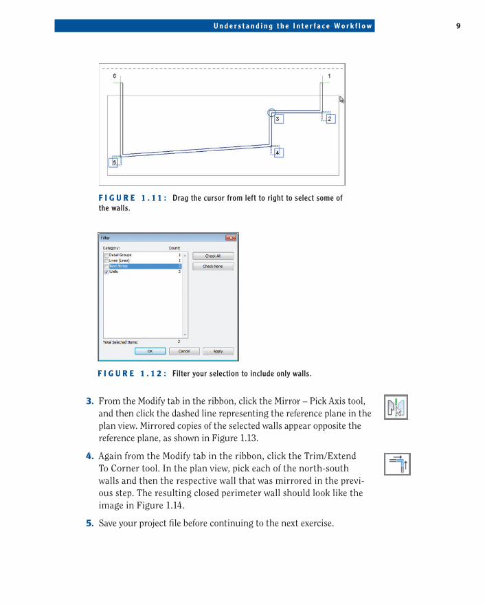
1. Using the mouse pointer, click and drag a window from the lower left to the upper right to select only the wall segments running east-west, as shown in Figure 1.11.
2. You’ll probably have more than just walls when you use this method of selection. To reduce the selection to only walls, click the Filter button in the ribbon, and clear all the check boxes except Walls, as shown in Figure 1.12.
244784c01.indd 8 3/16/12 10:44 AM
U n d e r s t a n d i n g t h e I n t e r f a c e Wo r k f l o w 9
F I g U r e 1 . 1 1 : Drag the cursor from left to right to select some of the walls.
F I g U r e 1 . 1 2 : Filter your selection to include only walls.
3. From the Modify tab in the ribbon, click the Mirror – Pick Axis tool, and then click the dashed line representing the reference plane in the plan view. Mirrored copies of the selected walls appear opposite the reference plane, as shown in Figure 1.13.
4. Again from the Modify tab in the ribbon, click the Trim/Extend To Corner tool. In the plan view, pick each of the north-south walls and then the respective wall that was mirrored in the previ-ous step. The resulting closed perimeter wall should look like the image in Figure 1.14.
5. Save your project file before continuing to the next exercise.
244784c01.indd 9 3/16/12 10:44 AM

1 0 C h a p t e r 1 • I n t r o d u c i n g t h e A u t o d e s k R e v i t A r c h i t e c t u r e I n t e r f a c e
F I g U r e 1 . 1 3 : Mirrored copies of the selected walls
F I g U r e 1 . 1 4 : Use the Trim/Extend To Corner tool to complete the perimeter walls.
244784c01.indd 10 3/16/12 10:44 AM
U n d e r s t a n d i n g t h e I n t e r f a c e Wo r k f l o w 1 1
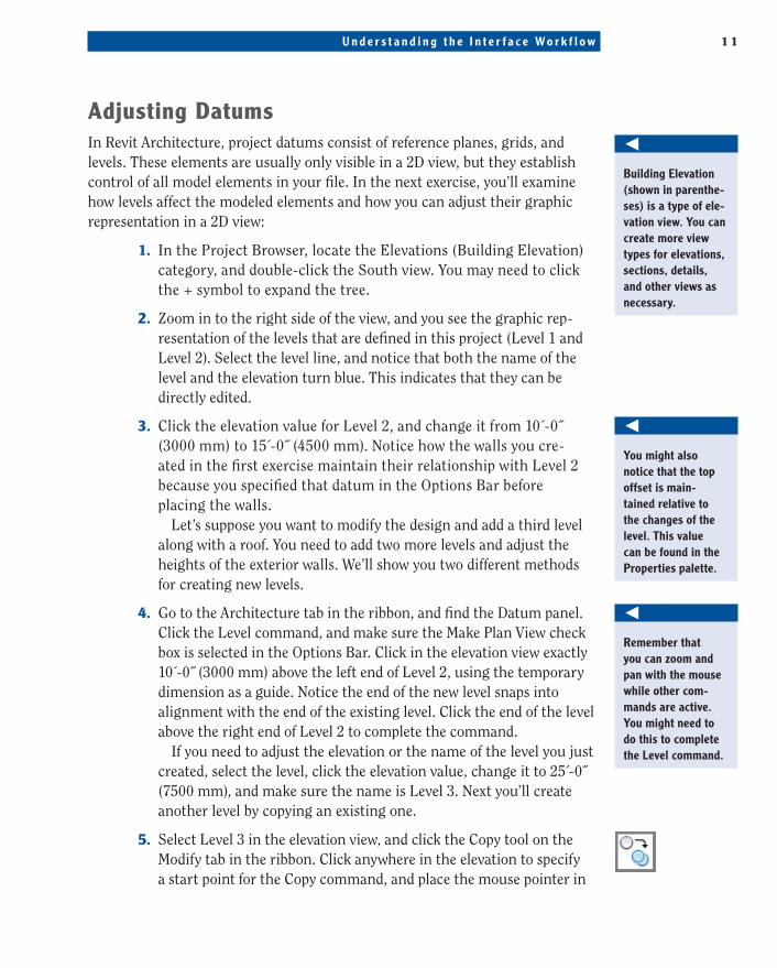
adjusting DatumsIn Revit Architecture, project datums consist of reference planes, grids, and levels. These elements are usually only visible in a 2D view, but they establish control of all model elements in your file. In the next exercise, you’ll examine how levels affect the modeled elements and how you can adjust their graphic representation in a 2D view:
1. In the Project Browser, locate the Elevations (Building Elevation) category, and double-click the South view. You may need to click the + symbol to expand the tree.
2. Zoom in to the right side of the view, and you see the graphic rep-resentation of the levels that are defined in this project (Level 1 and Level 2). Select the level line, and notice that both the name of the level and the elevation turn blue. This indicates that they can be directly edited.
3. Click the elevation value for Level 2, and change it from 10´-0˝ (3000 mm) to 15´-0˝ (4500 mm). Notice how the walls you cre-ated in the first exercise maintain their relationship with Level 2 because you specified that datum in the Options Bar before placing the walls.
Let’s suppose you want to modify the design and add a third level along with a roof. You need to add two more levels and adjust the heights of the exterior walls. We’ll show you two different methods for creating new levels.
4. Go to the Architecture tab in the ribbon, and find the Datum panel. Click the Level command, and make sure the Make Plan View check box is selected in the Options Bar. Click in the elevation view exactly 10´-0˝ (3000 mm) above the left end of Level 2, using the temporary dimension as a guide. Notice the end of the new level snaps into alignment with the end of the existing level. Click the end of the level above the right end of Level 2 to complete the command.
If you need to adjust the elevation or the name of the level you just created, select the level, click the elevation value, change it to 25´-0˝ (7500 mm), and make sure the name is Level 3. Next you’ll create another level by copying an existing one.
5. Select Level 3 in the elevation view, and click the Copy tool on the Modify tab in the ribbon. Click anywhere in the elevation to specify a start point for the Copy command, and place the mouse pointer in
O
BuildingElevation(shown in parenthe-ses) is a type of ele-vationview.Youcancreatemoreviewtypesforelevations,sections,details,andotherviewsasnecessary.
O
Youmightalsonotice that the top offset is main-tainedrelativetothe changes of the level.ThisvaluecanbefoundinthePropertiespalette.
O
Rememberthatyoucanzoomandpanwiththemousewhile other com-mandsareactive.Youmightneedtodo this to complete theLevelcommand.
244784c01.indd 11 3/16/12 10:44 AM
1 2 C h a p t e r 1 • I n t r o d u c i n g t h e A u t o d e s k R e v i t A r c h i t e c t u r e I n t e r f a c e
the upward (90$) direction. Type 12´-0˝ (3600 mm), and then press Enter to complete the command. Note that you can also press and hold the Shift key to force Copy or Move commands to operate in 90-degree increments.
6. Select the newest level, and change the name to Roof. Also make sure the elevation value is 37´-0˝ (11100 mm).
Note that when you copied the last level, a corresponding floor plan wasn’t created. This is indicated by the graphic level symbol being black instead of blue. You can double-click the blue level mark-ers to activate the associated plan view of that level. In addition, you can double-click any blue view symbol such as a section, an eleva-tion, or a callout.
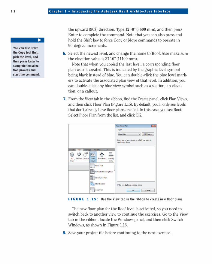
7. From the View tab in the ribbon, find the Create panel, click Plan Views, and then click Floor Plan (Figure 1.15). By default, you’ll only see levels that don’t already have floor plans created. In this case, you see Roof. Select Floor Plan from the list, and click OK.
F I g U r e 1 . 1 5 : Use the View tab in the ribbon to create new floor plans.
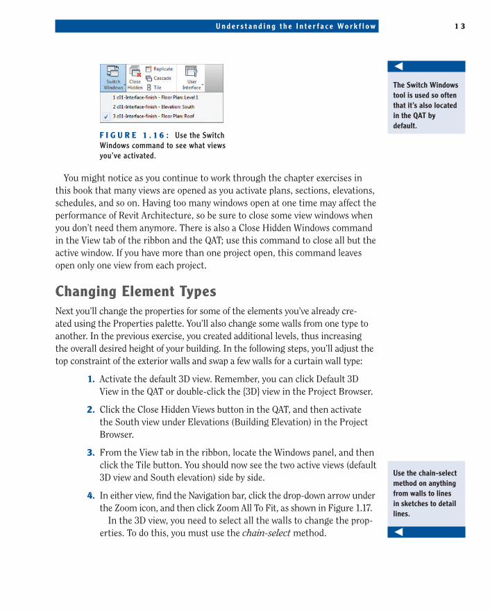
The new floor plan for the Roof level is activated, so you need to switch back to another view to continue the exercises. Go to the View tab in the ribbon, locate the Windows panel, and then click Switch Windows, as shown in Figure 1.16.
8. Save your project file before continuing to the next exercise.
�
YoucanalsostarttheCopytoolfirst,pickthelevel,andthenpressEntertocomplete the selec-tion process and startthecommand.
244784c01.indd 12 3/16/12 10:44 AM
U n d e r s t a n d i n g t h e I n t e r f a c e Wo r k f l o w 1 3
F I g U r e 1 . 1 6 : Use the Switch Windows command to see what views you’ve activated.
You might notice as you continue to work through the chapter exercises in this book that many views are opened as you activate plans, sections, elevations, schedules, and so on. Having too many windows open at one time may affect the performance of Revit Architecture, so be sure to close some view windows when you don’t need them anymore. There is also a Close Hidden Windows command in the View tab of the ribbon and the QAT; use this command to close all but the active window. If you have more than one project open, this command leaves open only one view from each project.
Changing element typesNext you’ll change the properties for some of the elements you’ve already cre-ated using the Properties palette. You’ll also change some walls from one type to another. In the previous exercise, you created additional levels, thus increasing the overall desired height of your building. In the following steps, you’ll adjust the top constraint of the exterior walls and swap a few walls for a curtain wall type:
1. Activate the default 3D view. Remember, you can click Default 3D View in the QAT or double-click the {3D} view in the Project Browser.
2. Click the Close Hidden Views button in the QAT, and then activate the South view under Elevations (Building Elevation) in the Project Browser.
3. From the View tab in the ribbon, locate the Windows panel, and then click the Tile button. You should now see the two active views (default 3D view and South elevation) side by side.
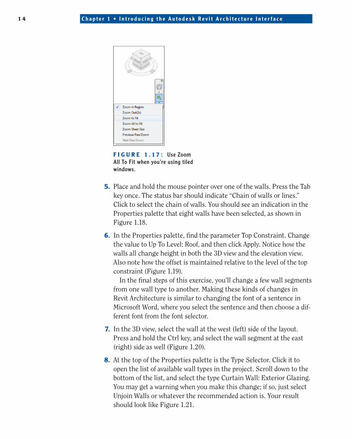
4. In either view, find the Navigation bar, click the drop-down arrow under the Zoom icon, and then click Zoom All To Fit, as shown in Figure 1.17.
In the 3D view, you need to select all the walls to change the prop-erties. To do this, you must use the chain-select method.
O
TheSwitchWindowstoolisusedsooftenthat it’s also located intheQATbydefault.
Use the chain-select method on anything from walls to lines in sketches to detail lines.
O
244784c01.indd 13 3/16/12 10:44 AM
1 4 C h a p t e r 1 • I n t r o d u c i n g t h e A u t o d e s k R e v i t A r c h i t e c t u r e I n t e r f a c e
F I g U r e 1 . 1 7 : Use Zoom All To Fit when you’re using tiled windows.
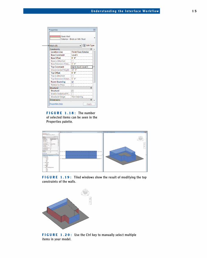
5. Place and hold the mouse pointer over one of the walls. Press the Tab key once. The status bar should indicate “Chain of walls or lines.” Click to select the chain of walls. You should see an indication in the Properties palette that eight walls have been selected, as shown in Figure 1.18.
6. In the Properties palette, find the parameter Top Constraint. Change the value to Up To Level: Roof, and then click Apply. Notice how the walls all change height in both the 3D view and the elevation view. Also note how the offset is maintained relative to the level of the top constraint (Figure 1.19).
In the final steps of this exercise, you’ll change a few wall segments from one wall type to another. Making these kinds of changes in Revit Architecture is similar to changing the font of a sentence in Microsoft Word, where you select the sentence and then choose a dif-ferent font from the font selector.
7. In the 3D view, select the wall at the west (left) side of the layout. Press and hold the Ctrl key, and select the wall segment at the east (right) side as well (Figure 1.20).
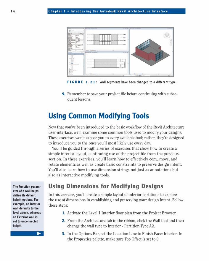
8. At the top of the Properties palette is the Type Selector. Click it to open the list of available wall types in the project. Scroll down to the bottom of the list, and select the type Curtain Wall: Exterior Glazing. You may get a warning when you make this change; if so, just select Unjoin Walls or whatever the recommended action is. Your result should look like Figure 1.21.
244784c01.indd 14 3/16/12 10:44 AM
U n d e r s t a n d i n g t h e I n t e r f a c e Wo r k f l o w 1 5
F I g U r e 1 . 1 8 : The number of selected items can be seen in the Properties palette.
F I g U r e 1 . 1 9 : Tiled windows show the result of modifying the top constraints of the walls.
F I g U r e 1 . 2 0 : Use the Ctrl key to manually select multiple items in your model.
244784c01.indd 15 3/16/12 10:44 AM
1 6 C h a p t e r 1 • I n t r o d u c i n g t h e A u t o d e s k R e v i t A r c h i t e c t u r e I n t e r f a c e
F I g U r e 1 . 2 1 : Wall segments have been changed to a different type.
9. Remember to save your project file before continuing with subse-quent lessons.
Using Common Modifying toolsNow that you’ve been introduced to the basic workflow of the Revit Architecture user interface, we’ll examine some common tools used to modify your designs. These exercises won’t expose you to every available tool; rather, they’re designed to introduce you to the ones you’ll most likely use every day.
You’ll be guided through a series of exercises that show how to create a simple interior layout, continuing use of the project file from the previous section. In these exercises, you’ll learn how to effectively copy, move, and rotate elements as well as create basic constraints to preserve design intent. You’ll also learn how to use dimension strings not just as annotations but also as interactive modifying tools.
Using Dimensions for Modifying DesignsIn this exercise, you’ll create a simple layout of interior partitions to explore the use of dimensions in establishing and preserving your design intent. Follow these steps:
1. Activate the Level 1 Interior floor plan from the Project Browser.
2. From the Architecture tab in the ribbon, click the Wall tool and then change the wall type to Interior - Partition Type A2.
3. In the Options Bar, set the Location Line to Finish Face: Interior. In the Properties palette, make sure Top Offset is set to 0.
TheFunctionparam-eter of a wall helps defineitsdefaultheightoptions.Forexample,anInteriorwalldefaultstothelevelabove,whereasanExteriorwallissettounconnectedheight.
�
244784c01.indd 16 3/16/12 10:44 AM
U s i n g C o m m o n M o d i f y i n g To o l s 1 7
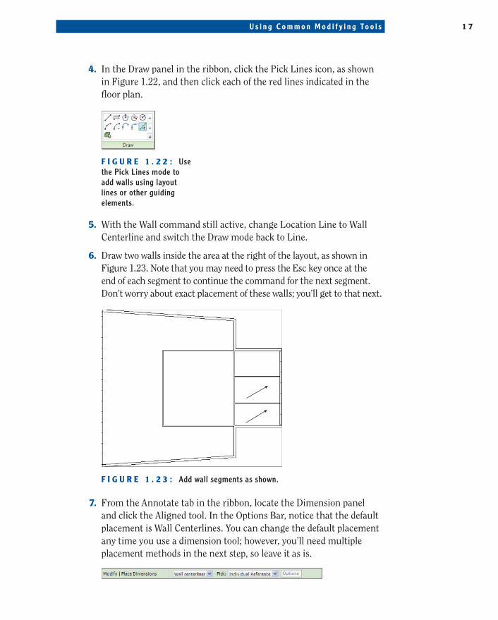
4. In the Draw panel in the ribbon, click the Pick Lines icon, as shown in Figure 1.22, and then click each of the red lines indicated in the floor plan.
F I g U r e 1 . 2 2 : Use the Pick Lines mode to add walls using layout lines or other guiding elements.
5. With the Wall command still active, change Location Line to Wall Centerline and switch the Draw mode back to Line.
6. Draw two walls inside the area at the right of the layout, as shown in Figure 1.23. Note that you may need to press the Esc key once at the end of each segment to continue the command for the next segment. Don’t worry about exact placement of these walls; you’ll get to that next.
F I g U r e 1 . 2 3 : Add wall segments as shown.
7. From the Annotate tab in the ribbon, locate the Dimension panel and click the Aligned tool. In the Options Bar, notice that the default placement is Wall Centerlines. You can change the default placement any time you use a dimension tool; however, you’ll need multiple placement methods in the next step, so leave it as is.
244784c01.indd 17 3/16/12 10:44 AM
1 8 C h a p t e r 1 • I n t r o d u c i n g t h e A u t o d e s k R e v i t A r c h i t e c t u r e I n t e r f a c e
8. In the plan view, click each of the two interior walls you just created. You see one dimension appear between the two walls, but the com-mand is still active. Keep going to the next step.
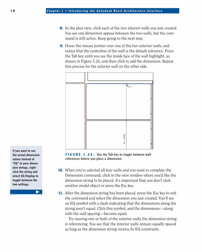
9. Hover the mouse pointer over one of the two exterior walls, and notice that the centerline of the wall is the default reference. Press the Tab key until you see the inside face of the wall highlight, as shown in Figure 1.24, and then click to add the dimension. Repeat this process for the exterior wall on the other side.
F I g U r e 1 . 2 4 : Use the Tab key to toggle between wall references before you place a dimension.
10. When you’ve selected all four walls and you want to complete the Dimension command, click in the view window where you’d like the dimension string to be placed. It’s important that you don’t click another model object or press the Esc key.
11. After the dimension string has been placed, press the Esc key to exit the command and select the dimension you just created. You’ll see an EQ symbol with a slash indicating that the dimensions along the string aren’t equal. Click this symbol, and the dimensions—along with the wall spacing—become equal.
Try moving one or both of the exterior walls the dimension string is referencing. You see that the interior walls remain equally spaced as long as the dimension string retains its EQ constraint.
Ifyouwanttoseetheactualdimensionvaluesinsteadof“EQ”inyourdimen-sionstrings,right-click the string and selectEQDisplaytotoggle between the twosettings.
�
244784c01.indd 18 3/16/12 10:44 AM
U s i n g C o m m o n M o d i f y i n g To o l s 1 9
12. Select the dimension string again, and click the EQ symbol to remove the equality constraint.
13. Select one of the two interior walls, and the dimension values to either side turn blue. Click the dimension between the interior wall and the exterior wall, and change the value to 12´-0˝ (3.6 m). Repeat this process for the other side.
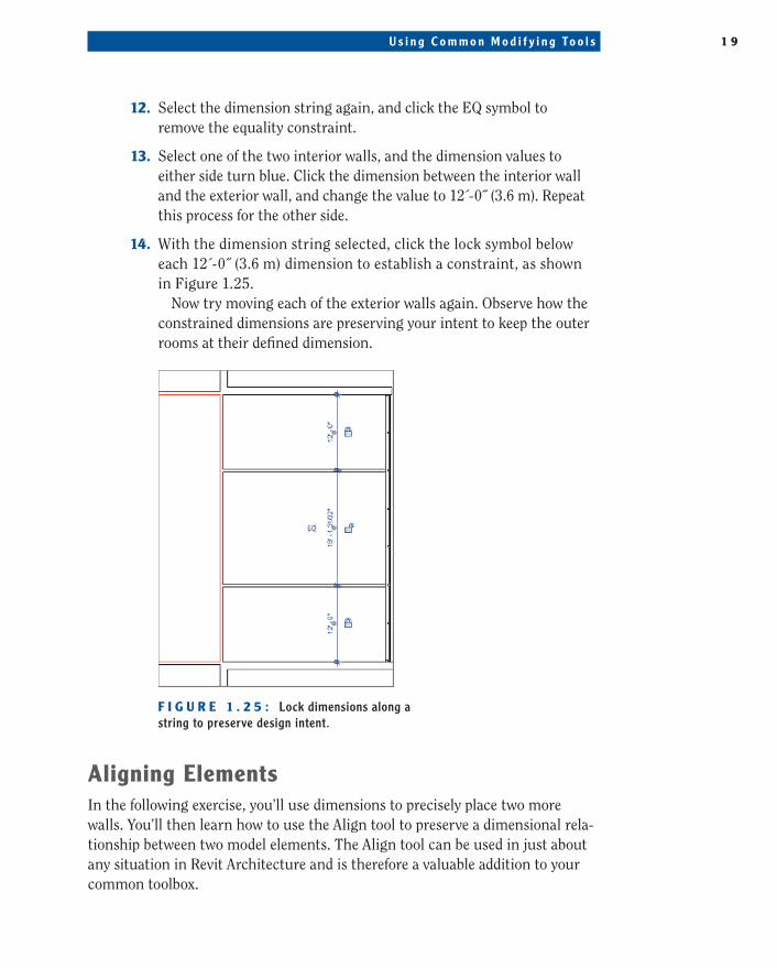
14. With the dimension string selected, click the lock symbol below each 12´-0˝ (3.6 m) dimension to establish a constraint, as shown in Figure 1.25.
Now try moving each of the exterior walls again. Observe how the constrained dimensions are preserving your intent to keep the outer rooms at their defined dimension.
F I g U r e 1 . 2 5 : Lock dimensions along a string to preserve design intent.
aligning elementsIn the following exercise, you’ll use dimensions to precisely place two more walls. You’ll then learn how to use the Align tool to preserve a dimensional rela-tionship between two model elements. The Align tool can be used in just about any situation in Revit Architecture and is therefore a valuable addition to your common toolbox.
244784c01.indd 19 3/16/12 10:44 AM
2 0 C h a p t e r 1 • I n t r o d u c i n g t h e A u t o d e s k R e v i t A r c h i t e c t u r e I n t e r f a c e
To begin this exercise, you’ll use temporary dimensions to place a wall segment. Elements in Revit Architecture can be initially placed in specific places using tem-porary dimensions, or you can place them and then modify their positions using temporary or permanent dimensions as you learned in the previous exercise.
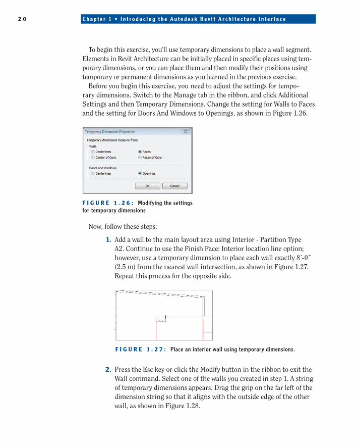
Before you begin this exercise, you need to adjust the settings for tempo-rary dimensions. Switch to the Manage tab in the ribbon, and click Additional Settings and then Temporary Dimensions. Change the setting for Walls to Faces and the setting for Doors And Windows to Openings, as shown in Figure 1.26.
F I g U r e 1 . 2 6 : Modifying the settings for temporary dimensions
Now, follow these steps:
1. Add a wall to the main layout area using Interior - Partition Type A2. Continue to use the Finish Face: Interior location line option; however, use a temporary dimension to place each wall exactly 8´-0˝ (2.5 m) from the nearest wall intersection, as shown in Figure 1.27. Repeat this process for the opposite side.
F I g U r e 1 . 2 7 : Place an interior wall using temporary dimensions.
2. Press the Esc key or click the Modify button in the ribbon to exit the Wall command. Select one of the walls you created in step 1. A string of temporary dimensions appears. Drag the grip on the far left of the dimension string so that it aligns with the outside edge of the other wall, as shown in Figure 1.28.
244784c01.indd 20 3/16/12 10:44 AM

U s i n g C o m m o n M o d i f y i n g To o l s 2 1
F I g U r e 1 . 2 8 : Adjust references of temporary dimensions by dragging grips.
3. Click the dimension icon just below the length shown in the tempo-rary dimension to convert it into a regular dimension string. Select the dimension string and click the lock symbol to establish a con-straint, as shown in Figure 1.29.
F I g U r e 1 . 2 9 : A temporary dimension has been converted and locked.
4. Zoom out so you can see both new interior wall segments. From the Modify tab in the ribbon, select the Align tool.
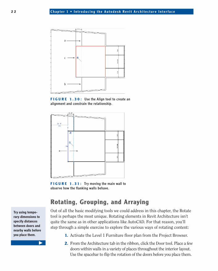
5. As illustrated in Figure 1.30, click the face of the wall that has been constrained in step 3 (a), click the corresponding face of the other new wall (b), and then click the lock to constrain the alignment (c).
Once you’ve completed this exercise, try moving the central interior wall to see how the two flanking walls maintain their dimensional and aligned relation-ships. Note that the constrained dimension can be deleted while preserving the constraint, as shown in Figure 1.31.
244784c01.indd 21 3/16/12 10:44 AM
2 2 C h a p t e r 1 • I n t r o d u c i n g t h e A u t o d e s k R e v i t A r c h i t e c t u r e I n t e r f a c e
a
c
b
F I g U r e 1 . 3 0 : Use the Align tool to create an alignment and constrain the relationship.
F I g U r e 1 . 3 1 : Try moving the main wall to observe how the flanking walls behave.
rotating, grouping, and arrayingOut of all the basic modifying tools we could address in this chapter, the Rotate tool is perhaps the most unique. Rotating elements in Revit Architecture isn’t quite the same as in other applications like AutoCAD. For that reason, you’ll step through a simple exercise to explore the various ways of rotating content:
1. Activate the Level 1 Furniture floor plan from the Project Browser.
2. From the Architecture tab in the ribbon, click the Door tool. Place a few doors within walls in a variety of places throughout the interior layout. Use the spacebar to flip the rotation of the doors before you place them.
Tryusingtempo-rary dimensions to specify distances between doors and nearby walls before youplacethem.
�
244784c01.indd 22 3/16/12 10:44 AM
U s i n g C o m m o n M o d i f y i n g To o l s 2 3
Note that you can disable automatic door tagging by clicking the Tag On Placement button in the contextual tab of the ribbon when the Door command is active.
3. From the Architecture tab in the ribbon, click the Component tool, and select Desk: Type D1 from the Type Selector.
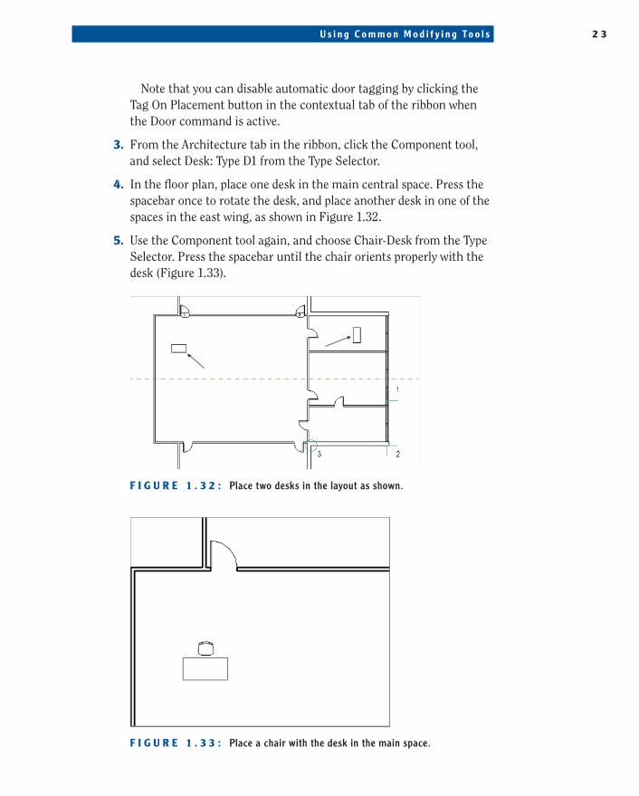
4. In the floor plan, place one desk in the main central space. Press the spacebar once to rotate the desk, and place another desk in one of the spaces in the east wing, as shown in Figure 1.32.
5. Use the Component tool again, and choose Chair-Desk from the Type Selector. Press the spacebar until the chair orients properly with the desk (Figure 1.33).
F I g U r e 1 . 3 2 : Place two desks in the layout as shown.
F I g U r e 1 . 3 3 : Place a chair with the desk in the main space.
244784c01.indd 23 3/16/12 10:44 AM
2 4 C h a p t e r 1 • I n t r o d u c i n g t h e A u t o d e s k R e v i t A r c h i t e c t u r e I n t e r f a c e
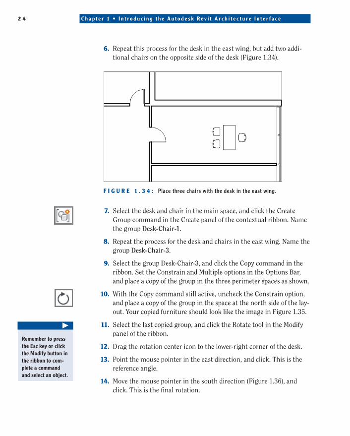
6. Repeat this process for the desk in the east wing, but add two addi-tional chairs on the opposite side of the desk (Figure 1.34).
F I g U r e 1 . 3 4 : Place three chairs with the desk in the east wing.
7. Select the desk and chair in the main space, and click the Create Group command in the Create panel of the contextual ribbon. Name the group Desk-Chair-1.
8. Repeat the process for the desk and chairs in the east wing. Name the group Desk-Chair-3.
9. Select the group Desk-Chair-3, and click the Copy command in the ribbon. Set the Constrain and Multiple options in the Options Bar, and place a copy of the group in the three perimeter spaces as shown.
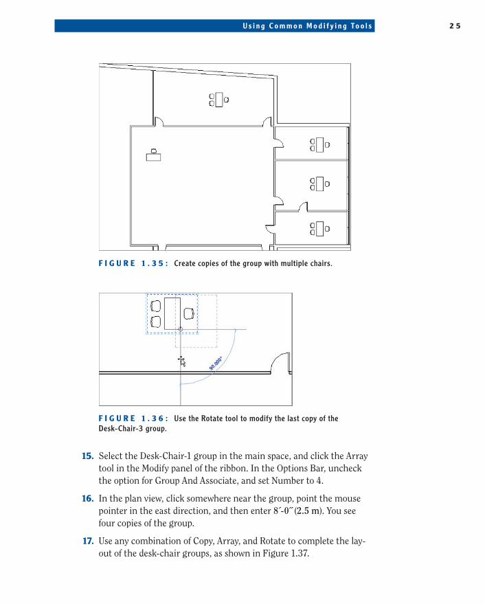
10. With the Copy command still active, uncheck the Constrain option, and place a copy of the group in the space at the north side of the lay-out. Your copied furniture should look like the image in Figure 1.35.
11. Select the last copied group, and click the Rotate tool in the Modify panel of the ribbon.
12. Drag the rotation center icon to the lower-right corner of the desk.
13. Point the mouse pointer in the east direction, and click. This is the reference angle.
14. Move the mouse pointer in the south direction (Figure 1.36), and click. This is the final rotation.
�
RemembertopresstheEsckeyorclicktheModifybuttoninthe ribbon to com-plete a command andselectanobject.
244784c01.indd 24 3/16/12 10:44 AM
U s i n g C o m m o n M o d i f y i n g To o l s 2 5
F I g U r e 1 . 3 5 : Create copies of the group with multiple chairs.
F I g U r e 1 . 3 6 : Use the Rotate tool to modify the last copy of the Desk-Chair-3 group.
15. Select the Desk-Chair-1 group in the main space, and click the Array tool in the Modify panel of the ribbon. In the Options Bar, uncheck the option for Group And Associate, and set Number to 4.
16. In the plan view, click somewhere near the group, point the mouse pointer in the east direction, and then enter 8´-0˝ (2.5 m). You see four copies of the group.
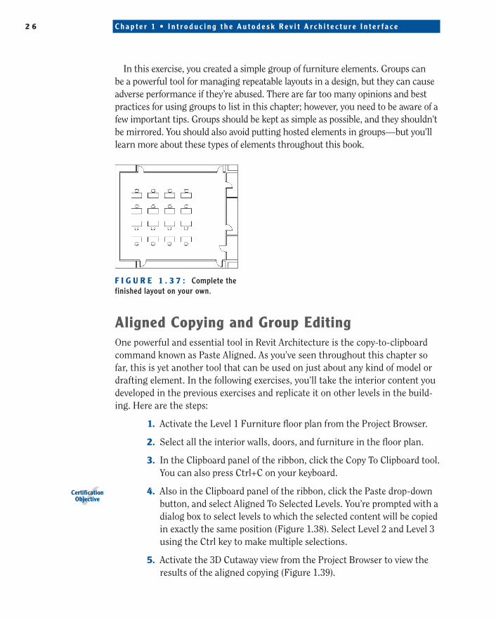
17. Use any combination of Copy, Array, and Rotate to complete the lay-out of the desk-chair groups, as shown in Figure 1.37.
244784c01.indd 25 3/16/12 10:44 AM
2 6 C h a p t e r 1 • I n t r o d u c i n g t h e A u t o d e s k R e v i t A r c h i t e c t u r e I n t e r f a c e
In this exercise, you created a simple group of furniture elements. Groups can be a powerful tool for managing repeatable layouts in a design, but they can cause adverse performance if they’re abused. There are far too many opinions and best practices for using groups to list in this chapter; however, you need to be aware of a few important tips. Groups should be kept as simple as possible, and they shouldn’t be mirrored. You should also avoid putting hosted elements in groups—but you’ll learn more about these types of elements throughout this book.
F I g U r e 1 . 3 7 : Complete the finished layout on your own.
aligned Copying and group editingOne powerful and essential tool in Revit Architecture is the copy-to-clipboard command known as Paste Aligned. As you’ve seen throughout this chapter so far, this is yet another tool that can be used on just about any kind of model or drafting element. In the following exercises, you’ll take the interior content you developed in the previous exercises and replicate it on other levels in the build-ing. Here are the steps:
1. Activate the Level 1 Furniture floor plan from the Project Browser.
2. Select all the interior walls, doors, and furniture in the floor plan.
3. In the Clipboard panel of the ribbon, click the Copy To Clipboard tool. You can also press Ctrl+C on your keyboard.
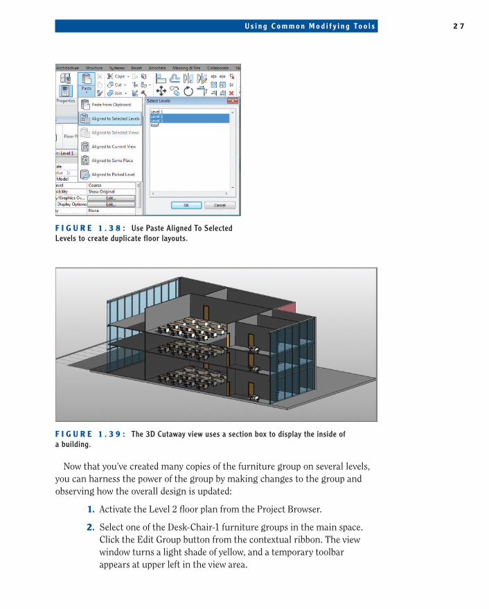
4. Also in the Clipboard panel of the ribbon, click the Paste drop-down button, and select Aligned To Selected Levels. You’re prompted with a dialog box to select levels to which the selected content will be copied in exactly the same position (Figure 1.38). Select Level 2 and Level 3 using the Ctrl key to make multiple selections.
5. Activate the 3D Cutaway view from the Project Browser to view the results of the aligned copying (Figure 1.39).
CertificationObjective
244784c01.indd 26 3/16/12 10:44 AM
U s i n g C o m m o n M o d i f y i n g To o l s 2 7
F I g U r e 1 . 3 8 : Use Paste Aligned To Selected Levels to create duplicate floor layouts.
F I g U r e 1 . 3 9 : The 3D Cutaway view uses a section box to display the inside of a building.
Now that you’ve created many copies of the furniture group on several levels, you can harness the power of the group by making changes to the group and observing how the overall design is updated:
1. Activate the Level 2 floor plan from the Project Browser.
2. Select one of the Desk-Chair-1 furniture groups in the main space. Click the Edit Group button from the contextual ribbon. The view window turns a light shade of yellow, and a temporary toolbar appears at upper left in the view area.
244784c01.indd 27 3/16/12 10:44 AM
2 8 C h a p t e r 1 • I n t r o d u c i n g t h e A u t o d e s k R e v i t A r c h i t e c t u r e I n t e r f a c e
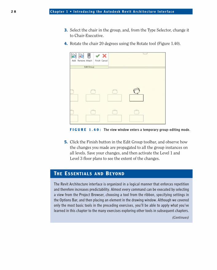
3. Select the chair in the group, and, from the Type Selector, change it to Chair-Executive.
4. Rotate the chair 20 degrees using the Rotate tool (Figure 1.40).
F I g U r e 1 . 4 0 : The view window enters a temporary group-editing mode.
5. Click the Finish button in the Edit Group toolbar, and observe how the changes you made are propagated to all the group instances on all levels. Save your changes, and then activate the Level 1 and Level 3 floor plans to see the extent of the changes.
The essenT ials and Beyond
The Revit Architecture interface is organized in a logical manner that enforces repetition and therefore increases predictability. Almost every command can be executed by selecting a view from the Project Browser, choosing a tool from the ribbon, specifying settings in the Options Bar, and then placing an element in the drawing window. Although we covered only the most basic tools in the preceding exercises, you’ll be able to apply what you’ve learned in this chapter to the many exercises exploring other tools in subsequent chapters.
(Continues)
244784c01.indd 28 3/16/12 10:44 AM
U s i n g C o m m o n M o d i f y i n g To o l s 2 9
The essenT ials and Beyond (Continued)
additional exercises
�� Use the Window and Door tools to place some hosted elements in the walls.
�� Create copies of these elements on other levels using the Copy-Paste Aligned tools.
�� Experiment with various ways to organize the Revit Architecture interface that support your preferred working method. Try tiling windows and undocking the Properties palette or the Project Browser.
�� Try a radial array of furniture by changing the Array tool settings in the Options Bar.
244784c01.indd 29 3/16/12 10:44 AM

244784c01.indd 30 3/16/12 10:44 AM