Embed Size (px)
Citation preview
Introducing the UML Eng. Mohammed T. Abo Alroos
Islamic University of Gaza
Introduction to the UML: The UML stands for Unified Modeling Language. It was released in 1997 as a method to diagram software design. It was designed by a consortium of the best minds in object oriented analysis and design. It is by far the most exciting thing to happen to the software industry in recent years. Every other engineering discipline has a standard method of documentation. Electronic engineers have schematic diagrams, architects and mechanical engineers have blueprints and mechanical diagrams. The software industry now has UML. Today, UML is accepted by the Object Management Group (OMG) as the standard for modeling object oriented programs.
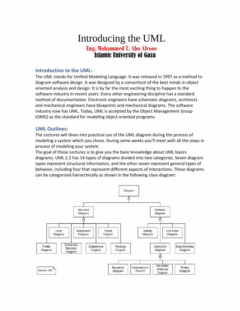
UML Outlines: The Lectures will dives into practical use of the UML diagram during the process of modeling a system which you chose. During some weeks you'll meet with all the steps in process of modeling your system. The goal of these Lectures is to give you the basic knowledge about UML basics diagrams. UML 2.2 has 14 types of diagrams divided into two categories. Seven diagram types represent structural information, and the other seven represent general types of behavior, including four that represent different aspects of interactions. These diagrams can be categorized hierarchically as shown in the following class diagram:
For Structure Diagram we will study: Class diagrams. For Behavior Diagram we will study: Use Case diagrams.
For Interaction Diagram we will study: Sequence diagrams.
UML Reality: Consider this, You tell a building contractor that you want a 4 bedroom, 3 bath home, about 2000 square feet, Start building it! >> We’ll hammer out the details as we go along? We all know this is ludicrous. But sadly, this method of development is all too common in the software industry. Just as you would work with an architect to design a blueprint that would diagram exactly how the house is to be built, you will work with us on an UML diagram that will document exactly how your custom software system will be built.
UML Benefits: 1 Your software system is professionally designed and documented
before it is coded. You will know exactly what you are getting, in advance.
2 The overall system design will dictate the way the software is developed. The
right decisions are made before you are married to poorly written code. Again, your overall costs will be less.
3 UML lets us see the big picture. We can develop more memory and
processor efficient systems.
4 When we come back to make modifications to your system, it is much easier to
work on a system that has UML documentation. Much less 'relearning' takes place. Your system maintenance costs will be lower.
5 If you should find the need to work with another developer, the UML diagrams
will allow them to get up to speed quickly in your custom system. Think of it as a schematic to a radio. How could a tech fix it without it?
6 If we need to communicate with outside contractors or even your own programmers, it is much more efficient.
Using the Unified Modeling Language will result in lower overall costs, more reliable and efficient software, and a better relationship with all parties involved. Software documented with UML can be modified much more efficiently. Your software will have a future.
UML Components: The UML certain number of graphical elements combined into diagrams. Because it is a language, the UML has rules for combining these elements, the purpose of the diagrams is to present multiple views of a system, and this set of multiple views is called a model. UML model describes what a system is supposed to do. It doesn't tell

how to implement the system.
Let's take a brief look of the selected UML diagrams.
Class Diagram Things naturally fall into categories (computers, automobiles, trees...). We refer to these categories as classes. A class is a category or group of things that have similar attributes and common behaviors.
o Object Diagram : An object is an instance of a class - a specific thing that has specific values of the attributes and behavior.
Use Case Diagram A use case is a description of a system's behavior from a user's standpoint. For system developers, this is a valuable tool: it's a tried-and-true technique for gathering system requirements from a user's point of view. That's important if the goal is to build a system that real people can use. In graphical representations of use cases a symbol for the actor is used. The actor is the entity that initiates the use case. It can be a person or another system.
Sequence Diagram Class diagrams and object diagrams represent static information. In a functioning system, however, objects interact with one another, and these interactions occur over time. The UML sequence diagram shows the time-based dynamics of the interaction.
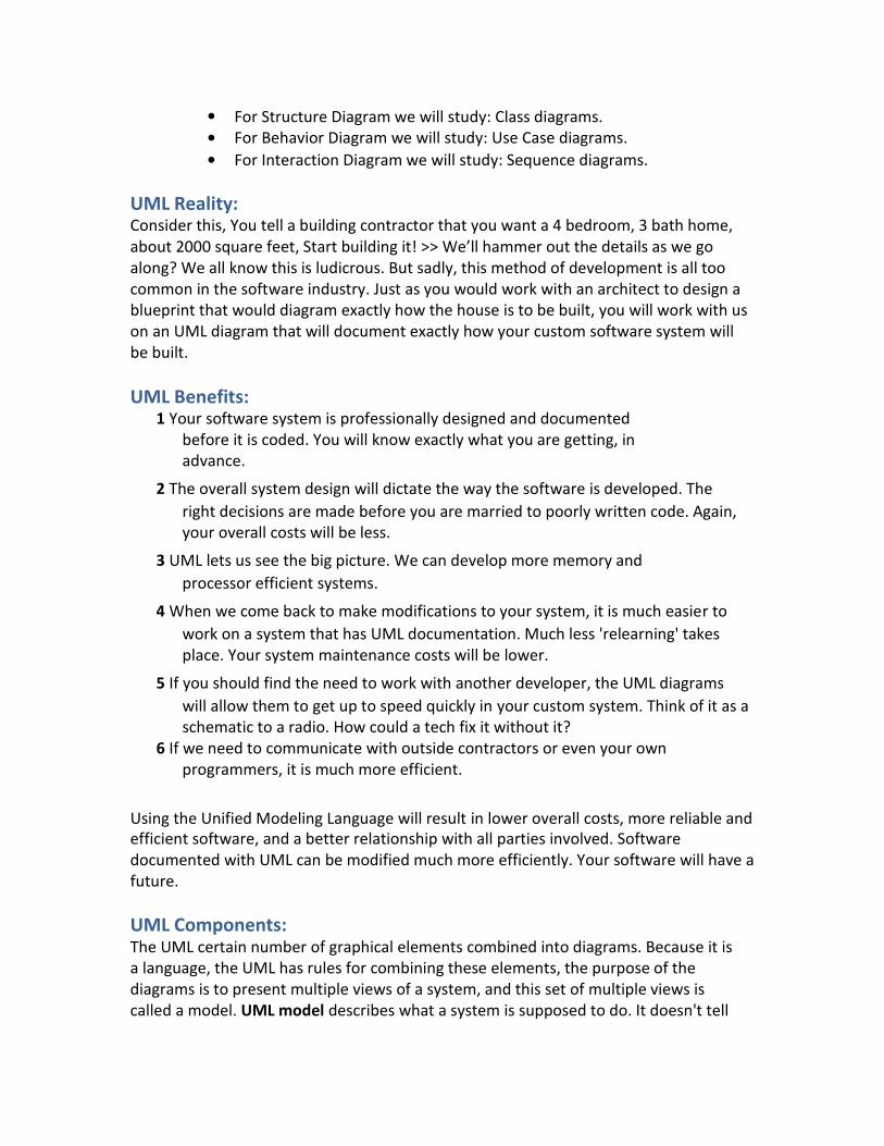
Class Diagram: Classes are composed of three things (a name, attributes, and operations)
Figure (1): An example of a class.
How to link each class with others?
1
2 3 4 5 6
Visualizing a Class (attributes and operations)
Associations Inheritance & Generalization Aggregations Interfaces & Realizations Visibilities
1 Visualizing a Class Are cleared before in the previous figure.
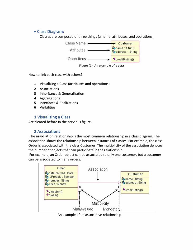
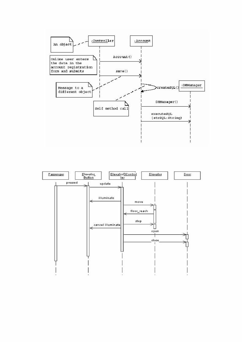
2 Associations The association relationship is the most common relationship in a class diagram. The
association shows the relationship between instances of classes. For example, the class Order is associated with the class Customer. The multiplicity of the association denotes the number of objects that can participate in the relationship. For example, an Order object can be associated to only one customer, but a customer
can be associated to many orders.
An example of an associative relationship
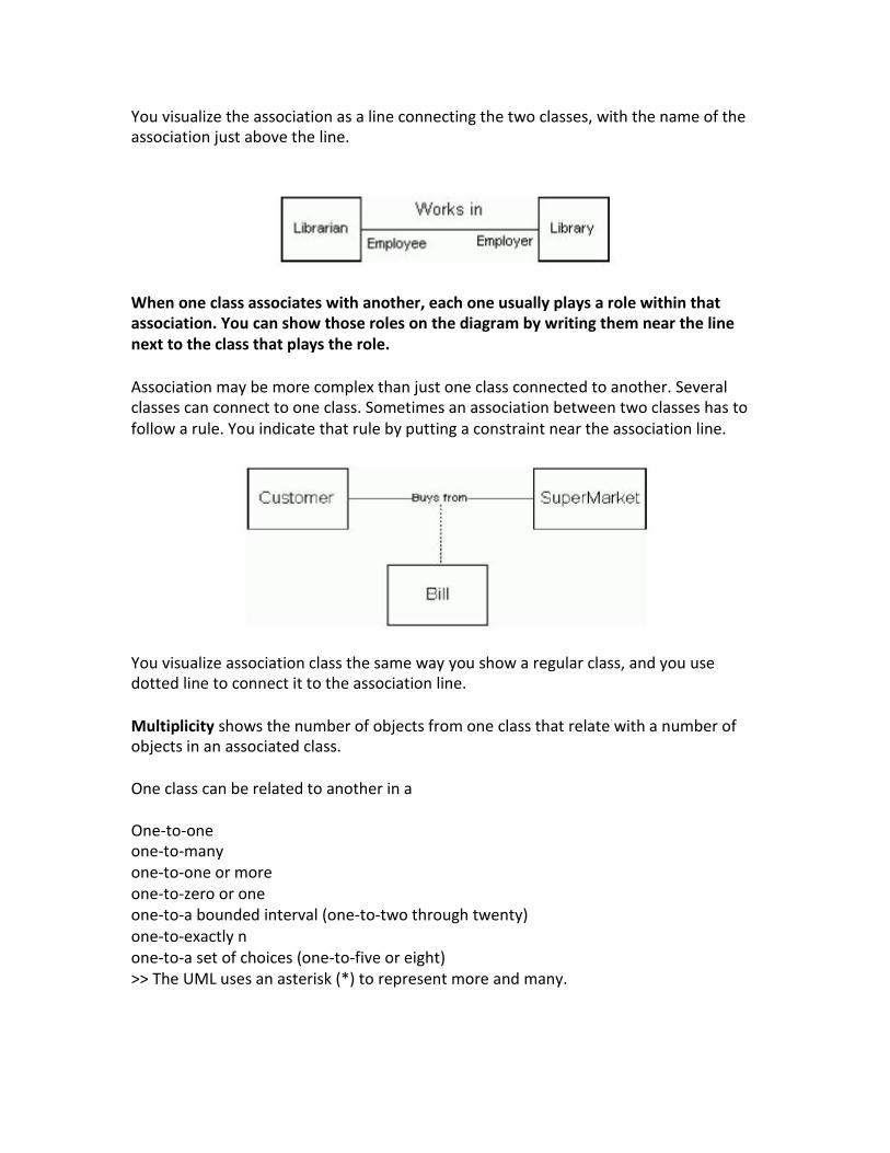
You visualize the association as a line connecting the two classes, with the name of the association just above the line.
When one class associates with another, each one usually plays a role within that association. You can show those roles on the diagram by writing them near the line next to the class that plays the role.
Association may be more complex than just one class connected to another. Several classes can connect to one class. Sometimes an association between two classes has to follow a rule. You indicate that rule by putting a constraint near the association line.
You visualize association class the same way you show a regular class, and you use dotted line to connect it to the association line.
Multiplicity shows the number of objects from one class that relate with a number of objects in an associated class.
One class can be related to another in a
One-to-one one-to-many one-to-one or more one-to-zero or one one-to-a bounded interval (one-to-two through twenty) one-to-exactly n one-to-a set of choices (one-to-five or eight) >> The UML uses an asterisk (*) to represent more and many.
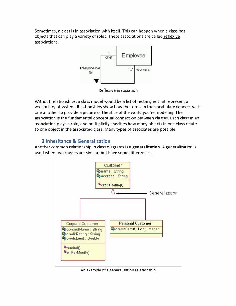
Sometimes, a class is in association with itself. This can happen when a class has objects that can play a variety of roles. These associations are called reflexive associations.
Reflexive association
Without relationships, a class model would be a list of rectangles that represent a vocabulary of system. Relationships show how the terms in the vocabulary connect with one another to provide a picture of the slice of the world you're modeling. The association is the fundamental conceptual connection between classes. Each class in an association plays a role, and multiplicity specifies how many objects in one class relate to one object in the associated class. Many types of associates are possible.
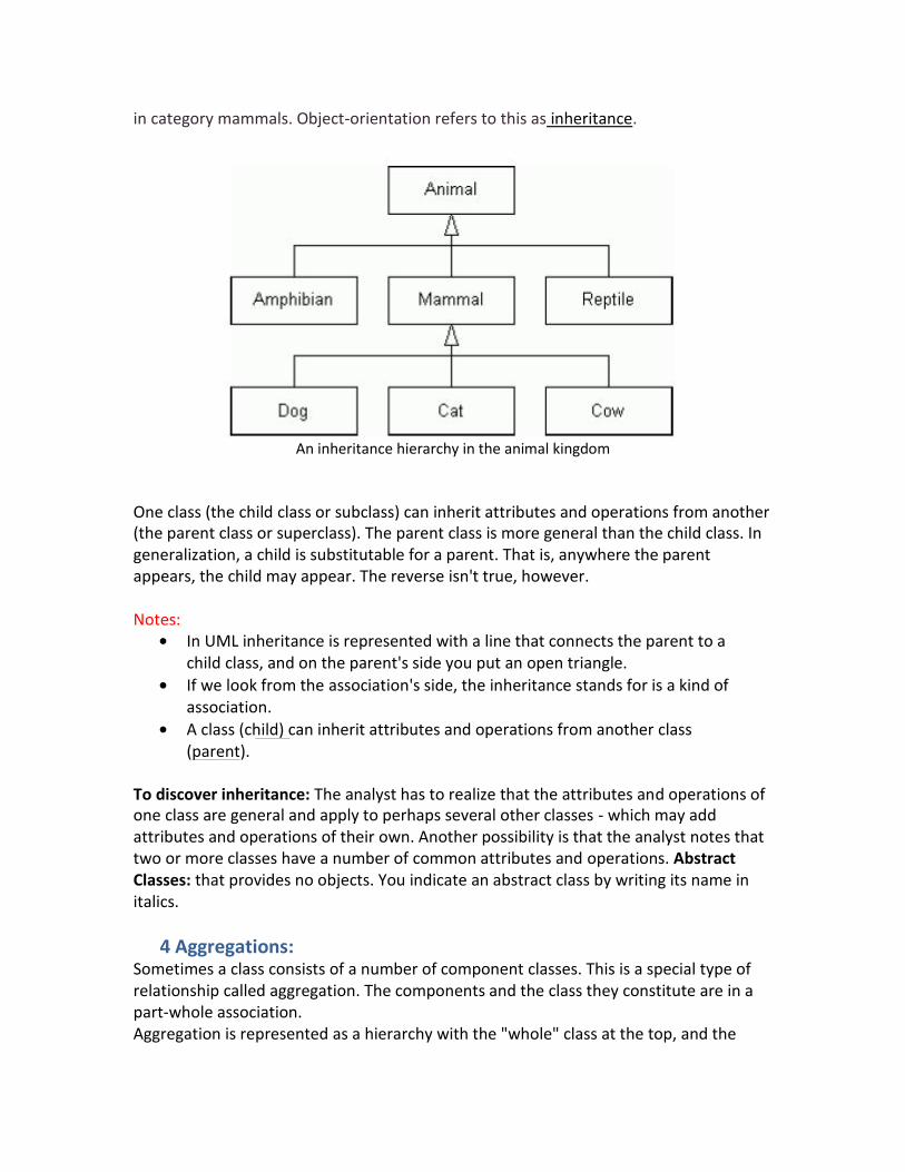
3 Inheritance & Generalization Another common relationship in class diagrams is a generalization. A generalization is used when two classes are similar, but have some differences.
An example of a generalization relationship

In this example the classes Corporate Customer and Personal Customer have some similarities such as name and address, but each class has some of its own attributes and operations. The class Customer is a general form of both the Corporate Customer and Personal Customer classes. This allows the designers to just use the Customer class for modules and do not require in-depth representation of each type of customer.
How to Draw: Class diagrams are some of the most difficult UML diagrams to draw. To draw detailed and useful diagrams a person would have to study UML and Object Oriented principles for a long time. Before drawing a class diagram consider the three different perspectives of the system the diagram will present; conceptual, specification, and implementation. Try not to focus on one perspective and try seeing how they all work together.
When designing classes consider what attributes and operations it will have. Then try to determine how instances of the classes will interact with each other. These are the very first steps of many in developing a class diagram. However, using just these basic techniques one can develop a complete view of the software system.
Another example:
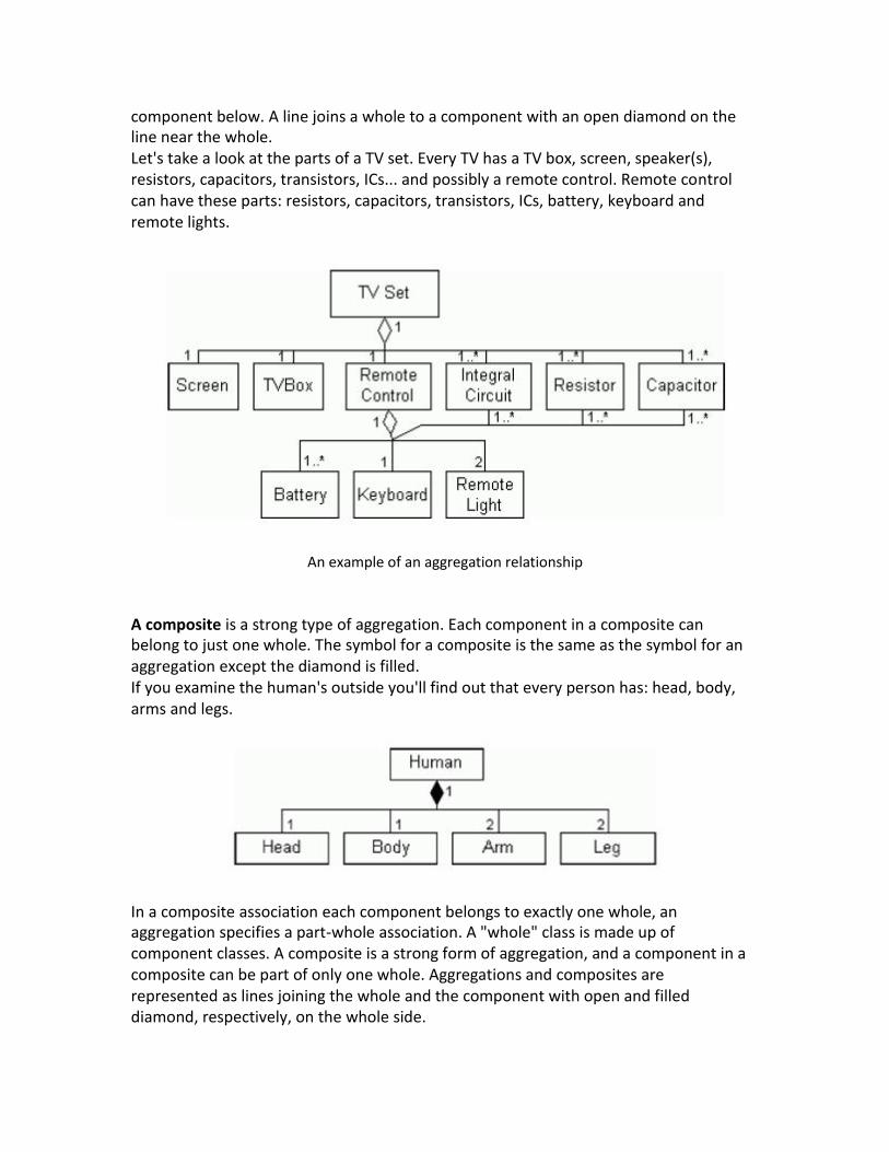
If you know something is an animal, you take for granted that it eats, sleeps, has a way of being born, and has a way of getting from one place to another... But imagine that mammals, amphibians and reptiles are all animals. Also cows, dogs, cats... are grouped
in category mammals. Object-orientation refers to this as inheritance.
An inheritance hierarchy in the animal kingdom
One class (the child class or subclass) can inherit attributes and operations from another (the parent class or superclass). The parent class is more general than the child class. In generalization, a child is substitutable for a parent. That is, anywhere the parent appears, the child may appear. The reverse isn't true, however.
Notes:
In UML inheritance is represented with a line that connects the parent to a child class, and on the parent's side you put an open triangle.
If we look from the association's side, the inheritance stands for is a kind of association.
A class (child) can inherit attributes and operations from another class (parent).
To discover inheritance: The analyst has to realize that the attributes and operations of one class are general and apply to perhaps several other classes - which may add attributes and operations of their own. Another possibility is that the analyst notes that two or more classes have a number of common attributes and operations. Abstract Classes: that provides no objects. You indicate an abstract class by writing its name in italics.
4 Aggregations: Sometimes a class consists of a number of component classes. This is a special type of relationship called aggregation. The components and the class they constitute are in a part-whole association. Aggregation is represented as a hierarchy with the "whole" class at the top, and the
component below. A line joins a whole to a component with an open diamond on the line near the whole. Let's take a look at the parts of a TV set. Every TV has a TV box, screen, speaker(s), resistors, capacitors, transistors, ICs... and possibly a remote control. Remote control can have these parts: resistors, capacitors, transistors, ICs, battery, keyboard and remote lights.
An example of an aggregation relationship
A composite is a strong type of aggregation. Each component in a composite can belong to just one whole. The symbol for a composite is the same as the symbol for an aggregation except the diamond is filled. If you examine the human's outside you'll find out that every person has: head, body, arms and legs.
In a composite association each component belongs to exactly one whole, an aggregation specifies a part-whole association. A "whole" class is made up of component classes. A composite is a strong form of aggregation, and a component in a composite can be part of only one whole. Aggregations and composites are represented as lines joining the whole and the component with open and filled diamond, respectively, on the whole side.
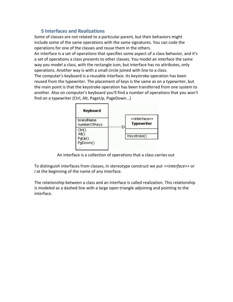
5 Interfaces and Realizations Some of classes are not related to a particular parent, but their behaviors might include some of the same operations with the same signatures. You can code the operations for one of the classes and reuse them in the others. An interface is a set of operations that specifies some aspect of a class behavior, and it's a set of operations a class presents to other classes. You model an interface the same way you model a class, with the rectangle icon, but interface has no attributes, only operations. Another way is with a small circle joined with line to a class. The computer's keyboard is a reusable interface. Its keystroke operation has been reused from the typewriter. The placement of keys is the same as on a typewriter, but the main point is that the keystroke operation has been transferred from one system to another. Also on computer's keyboard you'll find a number of operations that you won't find on a typewriter (Ctrl, Alt, PageUp, PageDown...)
An interface is a collection of operations that a class carries out
To distinguish interfaces from classes, in stereotype construct we put <<interface>> or I at the beginning of the name of any interface.
The relationship between a class and an interface is called realization. This relationship is modeled as a dashed line with a large open triangle adjoining and pointing to the interface.
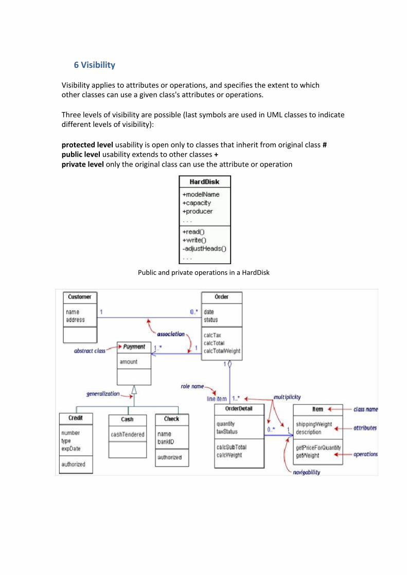
6 Visibility
Visibility applies to attributes or operations, and specifies the extent to which other classes can use a given class's attributes or operations.
Three levels of visibility are possible (last symbols are used in UML classes to indicate different levels of visibility):
protected level usability is open only to classes that inherit from original class # public level usability extends to other classes + private level only the original class can use the attribute or operation
Public and private operations in a HardDisk

Use Case Diagram:
Use Case Relationships
Three relationships among use cases are used often in practice.
Include In one form of interaction, a given use case may include another. "Include is a Directed Relationship between two use cases, implying that the behavior of the included use case is inserted into the behavior of the including use case" The first use case often depends on the outcome of the included use case. This is useful for extracting truly common behaviors from multiple use cases into a single description. The notation is a dashed arrow from the including to the included use case, with the label "«include»". This usage resembles a macro expansion where the included use case behavior is placed inline in the base use case behavior. There are no parameters or return values. To specify the location in a flow of events in which the base use case includes the behavior of another, you simply write include followed by the name of use case you want to include, as in the following flow for track order.
Extend In another form of interaction, a given use case (the extension) may extend another. This relationship indicates that the behavior of the extension use case may be inserted in the extended use case under some conditions[1]. The notation is a dashed arrow from the extension to the extended use case, with the label "«extend»". Notes or constraints may be associated with this relationship to illustrate the conditions under which this behaviour will be executed. Modelers use the «extend» relationship to indicate use cases that are "optional" to the base use case. Depending on the modeler's approach "optional" may mean "potentially not executed with the base use case" or it may mean "not required to achieve the base use case goal".
Generalization In the third form of relationship among use cases, a generalization/specialization relationship exists. A given use case may have common behaviors, constraints and assumptions to the general use case, describe them once, and deal with it in the same way, except for the details in the specialized cases. The notation is a solid line ending in a hollow triangle drawn from the specialized to the more general use case.

Sequence Diagram: Let us create a sample sequence diagram with the following functionality, using different sequence diagram symbols discussed above.
An Internet user enters data in an online registration form and submits it.
All user submissions are first received by a Controller object.
The Controller object creates an Account object with the data submitted by the user. The Account object creates and uses a DBManager object to save the data to a database.

GOOD LUCK


![[UML] UML, Metodologias e Ferramentas CASE us](https://img.pdfslide.net/doc/110x75/5571f34149795947648dbd59/uml-uml-metodologias-e-ferramentas-case-us.jpg)