Embed Size (px)
Citation preview
Introduction 1-1
Chapter 4Queuing, Datagrams, and Addressing
Computer Networking: A Top Down Approach 6th edition Jim Kurose, Keith RossAddison-WesleyMarch 2012
IC322Fall 2013
Some material copyright 1996-2012 J.F Kurose and K.W. Ross, All Rights Reserved
Network Layer 4-2
4.1 introduction4.2 virtual circuit and
datagram networks4.3 what’s inside a
router4.4 IP: Internet Protocol
datagram format IPv4 addressing ICMP IPv6
4.5 routing algorithms link state distance vector hierarchical routing
4.6 routing in the Internet RIP OSPF BGP
4.7 broadcast and multicast routing
Chapter 4: outline
Network Layer 4-3
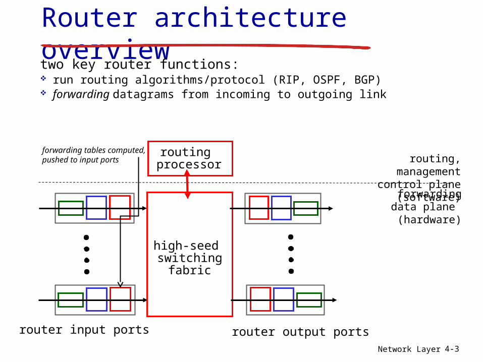
Router architecture overviewtwo key router functions: run routing algorithms/protocol (RIP, OSPF, BGP) forwarding datagrams from incoming to outgoing link
high-seed switching
fabric
routing processor
router input ports router output ports
forwarding data plane (hardware)
routing, managementcontrol plane (software)
forwarding tables computed,pushed to input ports
Network Layer 4-4
linetermination
link layer
protocol(receive)
lookup,forwarding
queueing
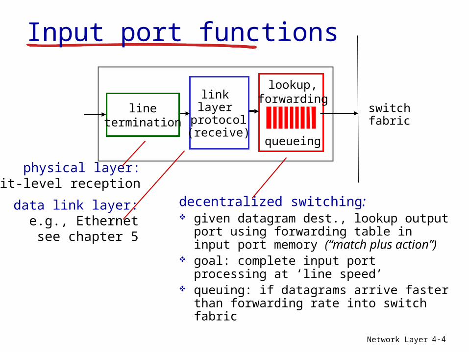
Input port functions
decentralized switching: given datagram dest., lookup output
port using forwarding table in input port memory (“match plus action”)
goal: complete input port processing at ‘line speed’
queuing: if datagrams arrive faster than forwarding rate into switch fabric
physical layer:bit-level reception
data link layer:e.g., Ethernetsee chapter 5
switchfabric
Network Layer 4-5
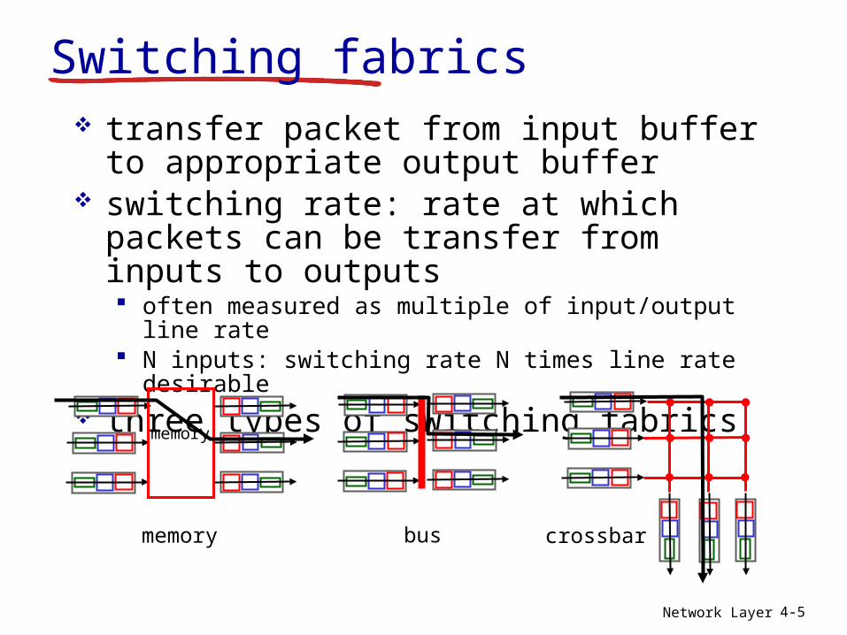
Switching fabrics transfer packet from input buffer to
appropriate output buffer switching rate: rate at which packets
can be transfer from inputs to outputs often measured as multiple of input/output line rate N inputs: switching rate N times line rate desirable
three types of switching fabrics
memory
memory
bus crossbar
Network Layer 4-6
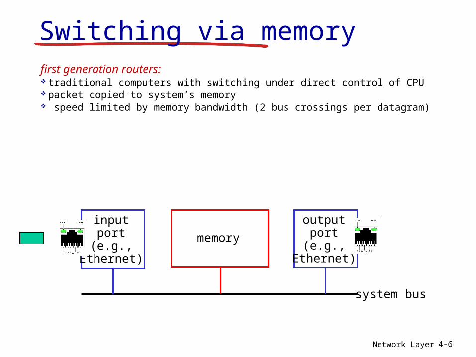
Switching via memoryfirst generation routers: traditional computers with switching under direct control of CPU packet copied to system’s memory speed limited by memory bandwidth (2 bus crossings per datagram)
inputport
(e.g.,Ethernet)
memory
outputport
(e.g.,Ethernet)
system bus
Network Layer 4-7
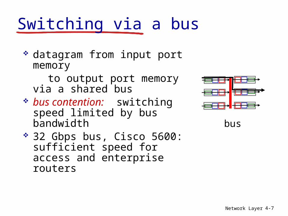
Switching via a bus
datagram from input port memory
to output port memory via a shared bus
bus contention: switching speed limited by bus bandwidth
32 Gbps bus, Cisco 5600: sufficient speed for access and enterprise routers
bus
Network Layer 4-8
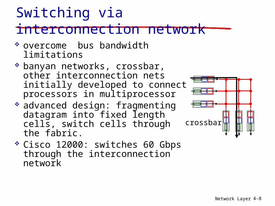
Switching via interconnection network overcome bus bandwidth
limitations banyan networks, crossbar,
other interconnection nets initially developed to connect processors in multiprocessor
advanced design: fragmenting datagram into fixed length cells, switch cells through the fabric.
Cisco 12000: switches 60 Gbps through the interconnection network
crossbar
Network Layer 4-9
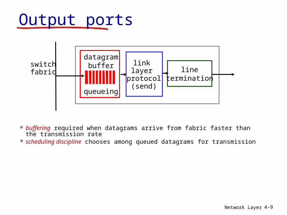
Output ports
buffering required when datagrams arrive from fabric faster than the transmission rate
scheduling discipline chooses among queued datagrams for transmission
linetermination
link layer
protocol(send)
switchfabric
datagrambuffer
queueing
Network Layer 4-10
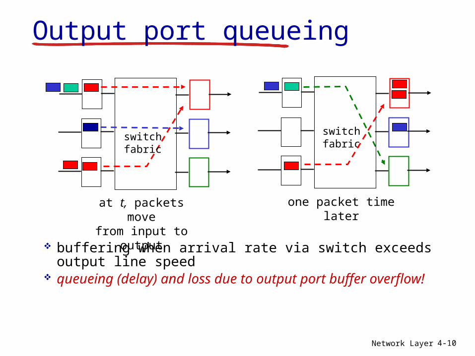
Output port queueing
buffering when arrival rate via switch exceeds output line speed
queueing (delay) and loss due to output port buffer overflow!
at t, packets movefrom input to output
one packet time later
switchfabric
switchfabric
Network Layer 4-11
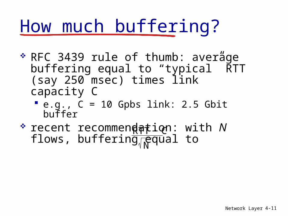
How much buffering?
RFC 3439 rule of thumb: average buffering equal to “typical” RTT (say 250 msec) times link capacity C e.g., C = 10 Gpbs link: 2.5 Gbit buffer
recent recommendation: with N flows, buffering equal to
RTT C.N
Network Layer 4-12
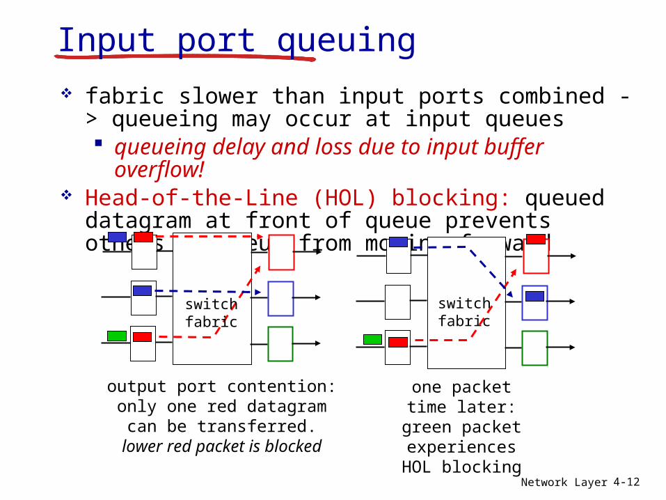
Input port queuing fabric slower than input ports combined ->
queueing may occur at input queues queueing delay and loss due to input buffer
overflow! Head-of-the-Line (HOL) blocking: queued
datagram at front of queue prevents others in queue from moving forward
output port contention:only one red datagram can
be transferred.lower red packet is blocked
switchfabric
one packet time later: green
packet experiences HOL
blocking
switchfabric
Network Layer 4-13
4.1 introduction4.2 virtual circuit and
datagram networks4.3 what’s inside a
router4.4 IP: Internet Protocol
datagram format IPv4 addressing ICMP IPv6
4.5 routing algorithms link state distance vector hierarchical routing
4.6 routing in the Internet RIP OSPF BGP
4.7 broadcast and multicast routing
Chapter 4: outline
Network Layer 4-14
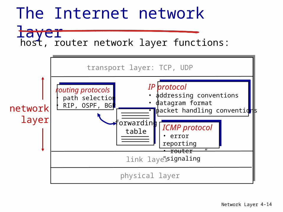
The Internet network layer
forwardingtable
host, router network layer functions:
routing protocols• path selection• RIP, OSPF, BGP
IP protocol• addressing conventions• datagram format• packet handling conventions
ICMP protocol• error reporting• router “signaling”
transport layer: TCP, UDP
link layer
physical layer
networklayer
Network Layer 4-15
ver length
32 bits
data (variable length,typically a TCP
or UDP segment)
16-bit identifier
header checksum
time tolive
32 bit source IP address
head.len
type ofservice
flgsfragment
offsetupper layer
32 bit destination IP address
options (if any)
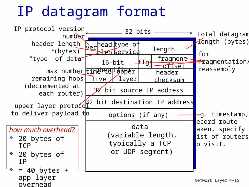
IP datagram formatIP protocol version
numberheader length
(bytes)
upper layer protocolto deliver payload to
total datagramlength (bytes)
“type” of data forfragmentation/reassemblymax number
remaining hops(decremented at
each router)
e.g. timestamp,record routetaken, specifylist of routers to visit.
how much overhead? 20 bytes of TCP 20 bytes of IP = 40 bytes + app
layer overhead
Network Layer 4-16
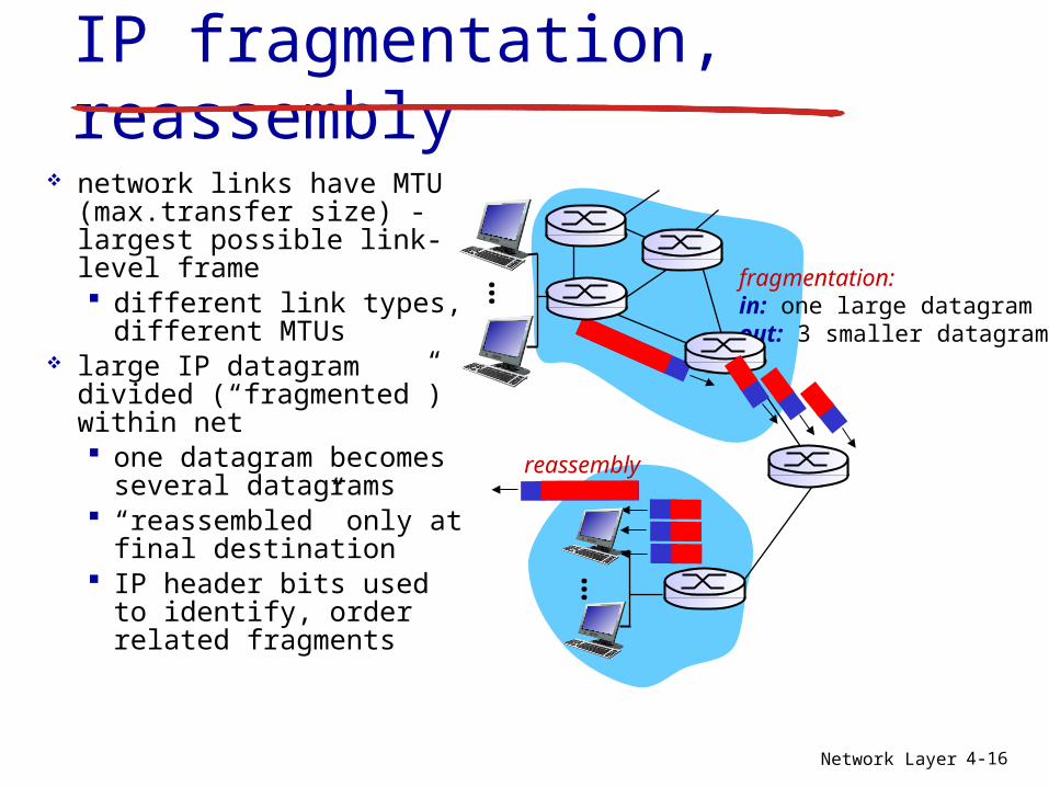
IP fragmentation, reassembly
network links have MTU (max.transfer size) - largest possible link-level frame different link types,
different MTUs large IP datagram
divided (“fragmented”) within net one datagram
becomes several datagrams
“reassembled” only at final destination
IP header bits used to identify, order related fragments
fragmentation: in: one large datagramout: 3 smaller datagrams
reassembly
…
…

Network Layer 4-17
ID=x
offset=0
fragflag=0
length=4000
ID=x
offset=0
fragflag=1
length=1500
ID=x
offset=185
fragflag=1
length=1500
ID=x
offset=370
fragflag=0
length=1040
one large datagram becomesseveral smaller datagrams
example: 4000 byte
datagram MTU = 1500
bytes1480 bytes in data field
offset =1480/8
IP fragmentation, reassembly
Network Layer 4-18
4.1 introduction4.2 virtual circuit and
datagram networks4.3 what’s inside a
router4.4 IP: Internet Protocol
datagram format IPv4 addressing ICMP IPv6
4.5 routing algorithms link state distance vector hierarchical routing
4.6 routing in the Internet RIP OSPF BGP
4.7 broadcast and multicast routing
Chapter 4: outline
Network Layer 4-19
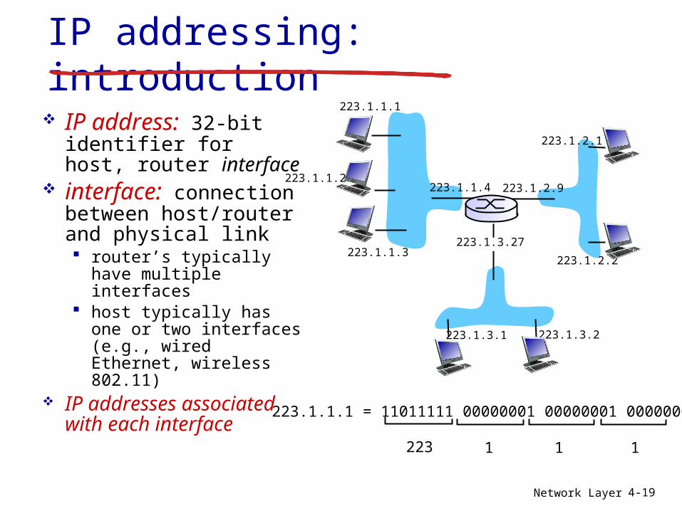
IP addressing: introduction
IP address: 32-bit identifier for host, router interface
interface: connection between host/router and physical link router’s typically have
multiple interfaces host typically has one
or two interfaces (e.g., wired Ethernet, wireless 802.11)
IP addresses associated with each interface
223.1.1.1
223.1.1.2
223.1.1.3
223.1.1.4 223.1.2.9
223.1.2.2
223.1.2.1
223.1.3.2223.1.3.1
223.1.3.27
223.1.1.1 = 11011111 00000001 00000001 00000001
223 1 11
Network Layer 4-20
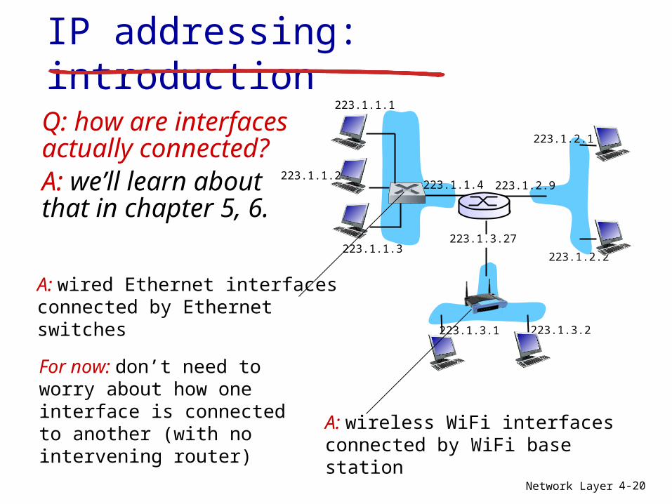
IP addressing: introduction
Q: how are interfaces actually connected?A: we’ll learn about that in chapter 5, 6.
223.1.1.1
223.1.1.2
223.1.1.3
223.1.1.4 223.1.2.9
223.1.2.2
223.1.2.1
223.1.3.2223.1.3.1
223.1.3.27
A: wired Ethernet interfaces connected by Ethernet switches
A: wireless WiFi interfaces connected by WiFi base station
For now: don’t need to worry about how one interface is connected to another (with no intervening router)
Network Layer 4-21
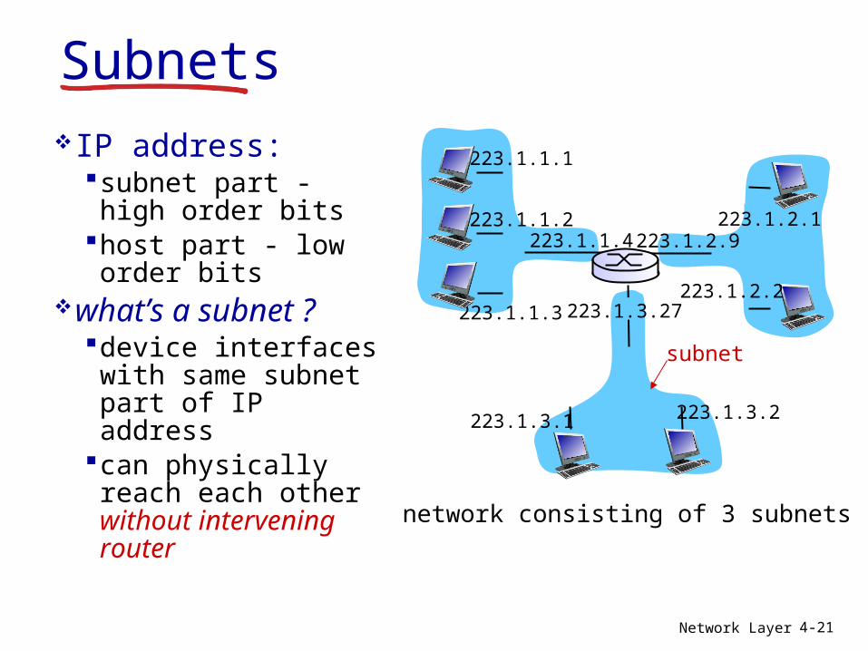
SubnetsIP address:
subnet part - high order bits
host part - low order bits
what’s a subnet ?device interfaces with same subnet part of IP address
can physically reach each other without intervening router
network consisting of 3 subnets
223.1.1.1
223.1.1.3
223.1.1.4 223.1.2.9
223.1.3.2223.1.3.1
subnet
223.1.1.2
223.1.3.27223.1.2.2
223.1.2.1
Network Layer 4-22
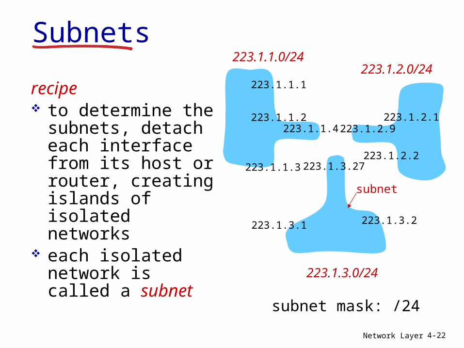
recipe to determine the
subnets, detach each interface from its host or router, creating islands of isolated networks
each isolated network is called a subnet
subnet mask: /24
Subnets223.1.1.0/24
223.1.2.0/24
223.1.3.0/24
223.1.1.1
223.1.1.3
223.1.1.4 223.1.2.9
223.1.3.2223.1.3.1
subnet
223.1.1.2
223.1.3.27223.1.2.2
223.1.2.1
Network Layer 4-23
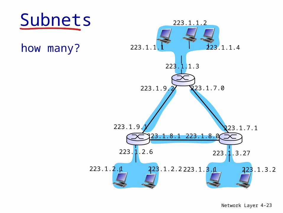
how many? 223.1.1.1
223.1.1.3
223.1.1.4
223.1.2.2223.1.2.1
223.1.2.6
223.1.3.2223.1.3.1
223.1.3.27
223.1.1.2
223.1.7.0
223.1.7.1223.1.8.0223.1.8.1
223.1.9.1
223.1.9.2
Subnets
Network Layer 4-24
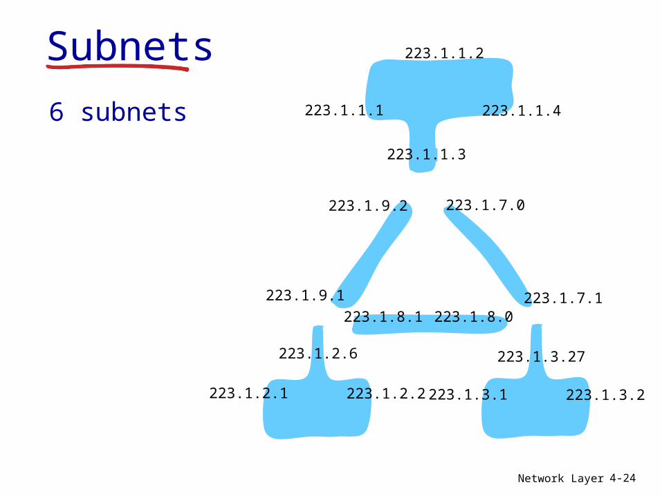
6 subnets 223.1.1.1
223.1.1.3
223.1.1.4
223.1.2.2223.1.2.1
223.1.2.6
223.1.3.2223.1.3.1
223.1.3.27
223.1.1.2
223.1.7.0
223.1.7.1223.1.8.0223.1.8.1
223.1.9.1
223.1.9.2
Subnets