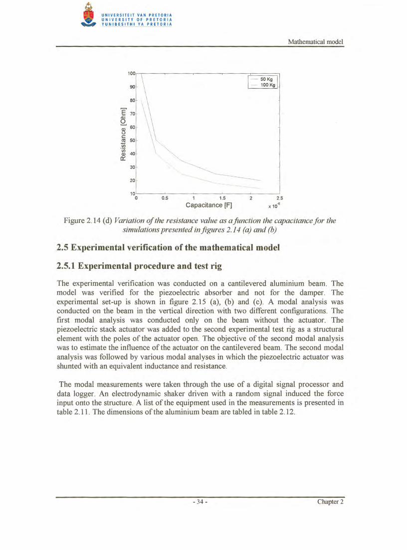
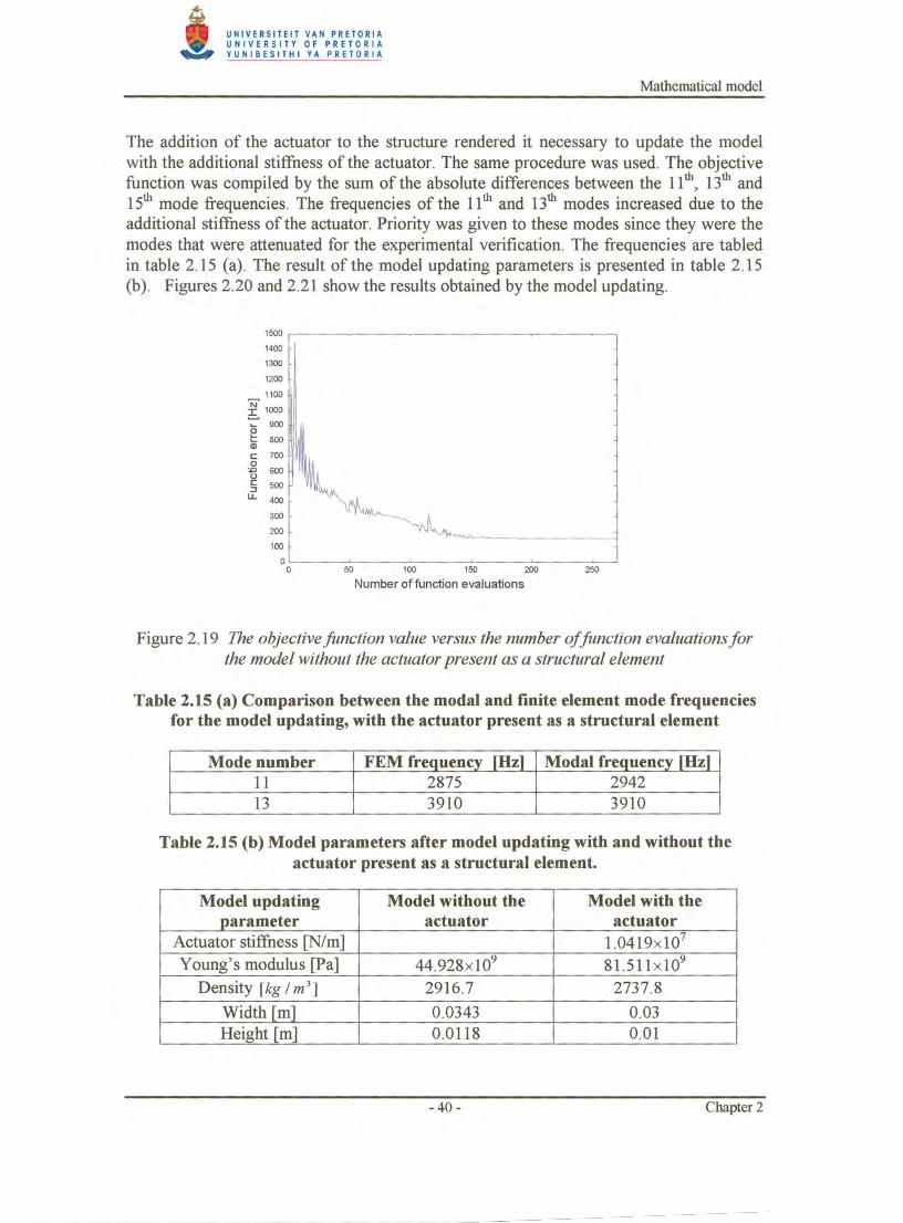
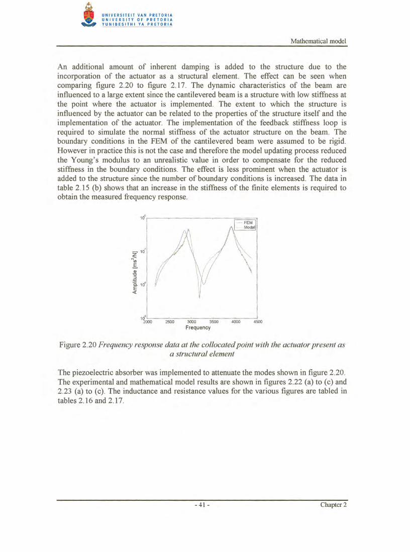
Embed Size (px)
Citation preview
Introduction and literature survey
Chapter 1
Introduction and literature survey 1.1 Introduction
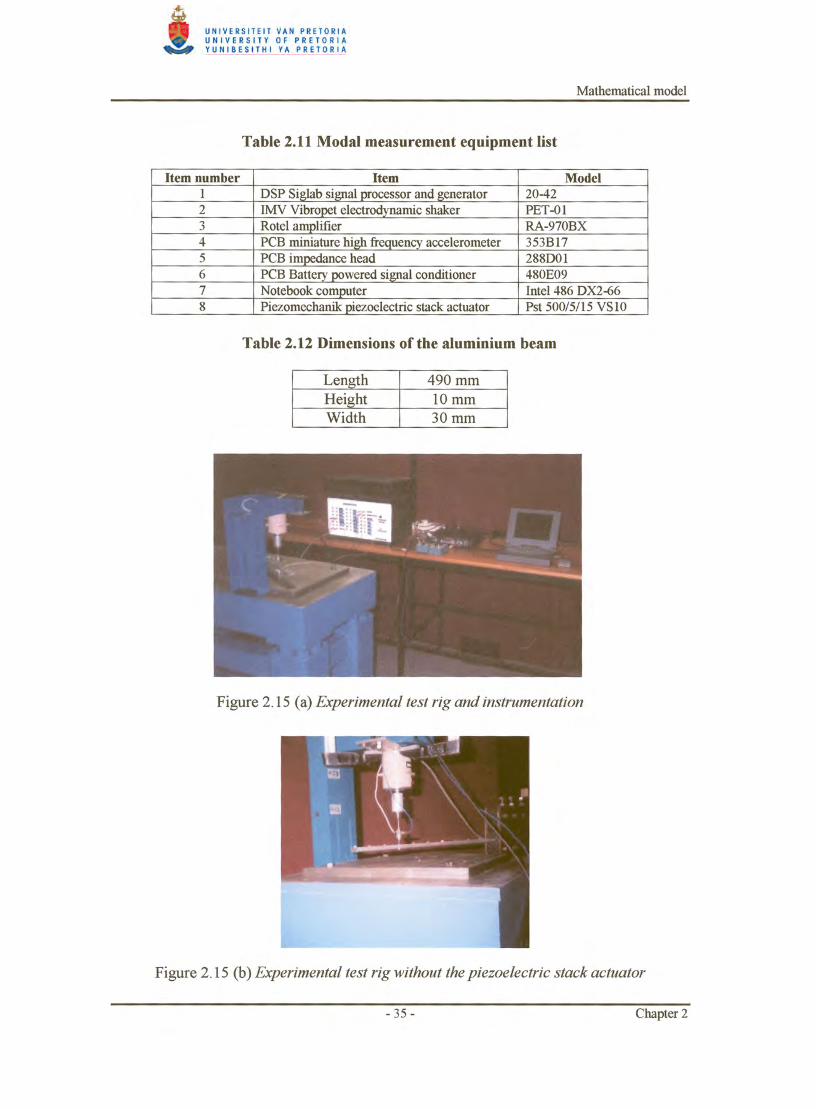
The attenuation of machine tool vibration is a field of research that has been the concern of many engineers over the past few decades. The driving force behind the ongoing research can be related to the fact that the level of vibration at the tool tip, limits the tool life as well as tolerances and the surface finish obtained by the machining process. Traditionally, the rate of material removal is reduced to obtain the required tolerances and surface finish. The reduction in rate of material removal reduces the efficiency of the machine, since the component manufacturing time is increased and lower production is obtained from the machine over a period of time. The objective of the vibration attenuation is to improve the dynamic stiffness of the machine tool structure, to increase the rate of material removal and thereby prolonging the life of the tool tip.
Acoustic noise emission during the machining process results from the relative motion between the tool tip and work piece. High levels of acoustic noise can cause discomfort in the working environment. The problem is related to the dynamic stiffness of the machine tool structure. By improving the dynamic stiffness of the structure, the level of noise emission from the machining process can be reduced.
During the material removal or cutting process, the toolholder and machine structure is subjected to dynamic excitation forces. If the dynamic force excites the modes of the structure, the response of the structure may reach hazardous proportions due to the excitation, depending on the amount of inherent damping in the structure. The problem of extreme structure response is addressed by adding artificial damping to the structure, or by shifting the modes of the structure to alternative frequencies which the dynamic force does not excite. The frequency shift is implemented with absorbers, and has limited frequency shift ability. However the frequencies may shift to a frequency that is still within the excitation frequency band and a damped vibration absorber is usuall y implemented to improve the attenuation results.
Active control of the tool tip response has become rather fashionable in both internal and external cutting processes over the past decade. The control design is either a feedback control system or a feed-forward control system, for the more advanced applications. The active control of machine tool vibration produces excellent results. The actuators used in the active control of machine tool vibration are usually piezoelectric actuators or magnetostrictive actuators. Piezoelectric ceramic materials are materials, which produce an electric field when strained by a force. When an electrical field is applied to the material, the material produces a strain. If the strain is restricted, a force is applied to the constraint by the material.
- 1 - Chapter 1
Introduction and literature survey
The magnetostnctlve actuator consists of a magnetostnctlve rod surrounded by an annular coil and a permanent magnet. If an electrical field is applied to the coil, the magnetostrictive rod produces a strain, as in the case of the piezoelectric actuator. These actuators are chosen for their high force per unit volume and operational frequency band characteristics. The control system consists of transducers, actuators, gain amplifiers, computation devices or electrical circuitry. Therefore considerable costs are involved in the implementation of such a system.
The properties of the piezoelectric and magnetostrictive actuators make them extremely attractive for the attenuation process. However, the cost of their implementation in the active control environment lessens this appeal. Recent advances in the field of research have lead to the implementation of these actuators as passive dampers and absorbers. The actuators are attached to a structure to alter the dynamic characteristics of the structure. A passive electrical circuit is connected in parallel to the poles of the actuators to adjust the dynamic behaviour of the actuator, and hence that of the structure. A vibration damper can be constructed by placing a resistor over the poles of the actuator. A vibration absorber can be constructed by adding an inductor in series with the resistor. The frequency of the absorber can be adjusted by varying the inductance of the circuit. The small size of the actuators, and the simplicity with which the absorption frequency can be changed, gives the concept an advantage over mechanical absorbers.
The technology has previously been implemented on beams and plates by various researchers. ACX Ltd. commercially implements the concept on snowboards, ski's and baseball bats to reduce the vibrations experienced by the sportsman. However, the challenge remains to determine the feasibility of implementing these actuators as passive structural elements in the attenuation of machine tool vibration.
1.2 Literature survey
The objective of this research was to implement a smart actuator with a passive electrical network, to attenuate machine tool vibration. The literature survey addressed the following topics:
• Passive damping features of the various smart actuators. • Vibration attenuation with piezoelectric actuators. • Active and passive control of machine tool vibration.
1.2.1 Passive damping features of the various smart actuators
An article by Smith and Anderson [2], on passive damping by the use of smart materials, deals with the selection of a suitable type of actuator for passive damping applications. The smart actuators considered in the paper were the piezoelectric, electrostrictive and magnetostrictive types. The article deals with the specific mechanisms used for the energy dissipation. A distinction is made between cases were the energy is dissipated internally, or externally, to the material of the attenuation device. In contrast to the traditional viscoelastic or viscous fluids where the energy dissipation occurs internally, the smart actuators that were considered employed external dissipation.
- 2 - Chapter 1
Introduction and literature survey
According to the article the viscoelastic materials and viscous fluids possess an internal structure which facilitates the dissipation of energy. The advantage of external energy dissipation is related to properties of the materials used in the vibration attenuation device. The properties of most materials vary with temperature change. The change might reduce the dissipation characteristics of some of the devices and in other cases it might complicate the design of the attenuation device. If the energy is dissipated externally, the characteristics of the attenuation device become insensitive to temperature change during the dissipation of the vibration energy.
The smart actuators are used as energy couplers to convert mechanical energy into electrical energy. The electrical energy is dissipated externally in an electric circuit. The electrical circuit consists of a resistive element, which is used to dissipate the electrical energy. In some of the electrical circuits, an inductor is added in series to the resistive element. The addition of the inductor causes the electrical circuit to resonate. By tuning the resonant frequency, additional vibration attenuation can be obtained. If a resistive element is placed over the poles of an actuator, the article states that the actuator is shunted resistively. In the case where an inductor and a resistive element are placed over the poles of the actuator, the article states that the actuator is shunted resistive-inductive. An actuator that is shunted resistively is called a damper and is analog to the design of viscoelastic materials as vibration dampers. An actuator that is shunted resistiveinductive is analog to a mechanically tuned damped mass absorber.
Piezoelectric actuators are perhaps the most straightforward to implement as passive dampers and absorbers, since the electromechanical coupling is linear and no external stimuli are required. The non-linear characteristics of the material can usually be ignored. The ceramic material, from which the piezoelectric actuator is built, is brittle and has high stiffness properties. Therefore, the actuators are less attractive for use as structural elements. The electromechanical coupling is relatively temperature insensitive, compared to the loss-producing mechanisms in viscous and viscoelastic materials. The use of piezoelectric elements in the longitudinal direction is preferred to the transverse direction for passive damping applications, since the electromechanical coupling is much higher in the longitudinal direction. The term longitudinal refers to the instance were the deformation of the material is perpendicular to the electrodes of the element. The transverse case refers to the instance where the deformation of the material occurs in parallel with the electrodes of the element. In general practice, the transverse case is referred to as a wafer and a piezoelectric stack actuator is the term used for a multi layered longitudinal configuration co-fired into one solid.
Electrostrictive materials appear to be feasible for passive vibration damping, but have limited use. Smith and Anderson indicate that electrostrictive materials such as leadmagnesium-niobate are often used as direct replacements for piezoelectric actuators in micro-positioning systems. The electrostrictive material has the disadvantages of high permittivity and relatively strong temperature dependence.
- 3 - Chapter 1
Introduction and literature survey
Due to the non-linear characteristic of the electromechanical coupling, the electrostrictive materials cannot be used to couple energy to an external dissipation system, without the addition of an external DC electric field . The field biases the electrostrictive coupler to a point of nonzero slope on the quadratic field-strain curve. The electrostrictive actuator is therefore biased and shunted with an electrical circuit to attenuate vibration. The shunting circuit resembles that of the piezoelectric case. The DC field is added in series with the shunt circuit, which in turn is coupled in parallel over the poles of the actuator. The lower the shunt frequency, the higher the required inductance value for resistive-inductive shunted piezoelectric and electrostrictive actuators. The relatively higher capacitance value of the electrostrictive actuator, in comparison with the piezoelectric actuators, reduces the required inductance value for the shunt circuit. The property of reduced inductance requirement is attractive but the necessity of an external electric field makes the option less so. The required inductance value versus actuator capacitance value will be dealt with in chapter 2 of the dissertation. The effectiveness of the circuit has not been verified experimentally.
Magnetostriction is a transduction process in which magnetic energy is converted to mechanical energy. It is also possible to invert the process. The transduction from mechanical to electrical energy in the magnetostrictive actuator is attained when the material of the actuator is stressed. When the material is stressed, the magnetic domains within the material rotate and alter the permeability of the material. In the presence of an electric bias field, the magnetic flux in the vicinity of the magnetostrictive varies as the external load varies. The change in the flux induces an electromotive force (emf) in the adjacent coil. The induced emf drives a current through the resistor. The magnetostrictive actuators are shunted with resistors as in the case of piezoelectric and electrostrictive actuators, however they are not shunted with resistive-inductance circuits. The most commonly available example of a magnetostrictive material must be Terfenol-D. Terfenol-D has the ability to extract large amounts of strain energy from a structure. The material has high stiffness, high power density, low operating voltages, and is thermalinsensitive.
The magnetostrictive and electrostrictive actuators impose difficulties due to the nonlinear characteristics and external stimuli. The advantages of smart materials are the tuning ability and the temperature insensitivity_ Of the three materials considered, the piezoelectric actuator is the most practical.
1.2.2 Vibration attenuation with piezoelectric actuators
The possibility of using piezoelectric materials as passive elements to attenuate vibration was first proposed by Forward [3] in 1979. Forward bonded piezoelectric elements to a beam and shunted the elements with an inductor. He significantly reduced the vibration levels of the beam at a resonant mode frequency of the beam.
- 4 - Chapter 1
Introduction and literature survey
A respected paper in the field of passive piezoelectric vibration attenuation is that of Hagood and Von Flotow [4]. They presented the first research that implemented a resistor shunt to enhance the damping of the structure to which the piezoelectric actuator is attached. The article derives a complete mathematical model for the piezoelectric damper and absorber. The article focuses on the piezoelectric wafers and verifies the mathematical model by implementing the wafers on an aluminium-cantilevered beam. The first mode of the beam was damped and absorbed experimentally. The article presents techniques to determine the optimal resistance and inductance values for the damper and absorber based on the implementation of a piezoelectric wafer element on a structure.
The amount of damping added to a structural mode of a plate structure, through the addition of shunted piezoelectric wafer element, is related to the ratio of strain energy captured by the piezoelectric element to the modal strain energy in the system. The concept is known as the modal strain energy approach and was initially proposed by Hagood and Von Flotow [4] for a single degree of freedom model. Davis and Lesieutre [5] did further development on the modal strain energy approach too extend its use too finite element modelling. Therefore, the amount of damping obtained can be improved by increasing the amount of wafers, to capture more of the strain energy, The modal strain energy approach is used to optimise the positioning of shunted wafer elements, on plate structures, to obtain optimal damping results ,
A literature survey conveying the evolution of piezoelectric shunting analysis is presented by Lesieutre [6]. The survey presents two new forms of shunting analysis namely the capacitive and switched shunts. The capacitive circuit is used to alter the stiffness of the piezoelectric element. The concept is implemented by Davis and Lesieutre [7] to develop an active tuned mechanical vibration absorber. The piezoelectric element provided the stiffness of the device, which granted the researchers the ability to electrically tune the stiffness of their damper. The switched shunt circuit apparently offers the possibility of controlling the energy transfer to reduce frequency dependent behaviour. The concept of switch shunt circuits refers to the research of Warkentin and Hagood [8]. According to Lesieure little research has addressed the topics of capacitive and switched shunting.
In his literature survey Inman [9] reports on the use of smart actuators as passive and active structural elements to solve structural vibration problems. The body of the article focuses on piezoelectric actuators to attenuate vibration. The article reviews the use of piezoelectric actuators as passive dampers, absorbers, and active control actuators. The working principle and implementation of the passive piezoelectric damper and absorber described correspond to that of Smith and Anderson [2]. The article states that passive electronic damping has become a viable alternative to passive viscoelastic damping. The article reveals an experimental case study where the first two modes of a cantilevered beam is suppressed individually by shunting two piezoelectric wafers resistive-inductive, The vibration amplitudes of the beam were decreased about 25 dB and 20 dB at the first and second mode frequencies, respectively.
- 5 - Chapter 1
Introduction and literature survey
Browning and Woodson [lO] indicated that it is possible to attenuate twelve different modes of a clamped-clamped steel plate with four piezoelectric wafer elements. They developed a wide band passive electronic shunt circuit for each of the four piezoelectric wafer elements that are coupled to attenuate the twelve structural modes.
A reduction of 20 dB for some of the structural modes is measured simultaneously over the frequency band. Browning and Wynn [10] admit that their finite element model of the plate suffered from potential inaccuracies in geometric and boundary condition modelling. Therefore, they based their analysis on an experimental modal model of the assembled test system. The system was exited with an electrodynamic shaker driven by a white noise signal, and a transfer function analysis was used to identify optimal wafer placement.
Edberg et al. [11] attenuated multiple modes of a structure with a single piezoelectric element. Variable synthetic inductors were used in the system. The synthetic inductor is known as a gyrator [12, 13] which is an electronic circuit consisting of one or two operational amplifiers, a real capacitor and a number of resistors. Edberg and colleagues substituted one of the feedback resistors with a variable resistor to obtain a variable synthetic inductor.
The Active Control Experts from Cambridge, Massachusetts designed the only known commercial implementations of the passive piezoelectric dampers and absorbers in their snowboards, ski's and baseball bats. The article regarding their snowboard design [14] states, that the piezoelectric based dampers outperform conventional dampers in a more compact package. The vibration in snowboards lessens the contact area between the board edge and snow surface. The reduced contact area leads to loss of control, stability and the maximum board speed. The resistive shunted piezoelectric actuators convert about 10 % of mechanical vibration energy into heat, which is on par with other passive dampers. A comparison of piezoelectric dampers to conventional options such as constrained layer viscoelastic dampers and absorbing foams shows piezoelectric damping systems are more expensive and require more design effort. Therefore, the concept is not cost-effective for small vibration control applications. It is recommended that the piezoelectric actuator should be mounted at areas of maximum strain for the modes of interest. A detailed structural model and modal analysis are required to optimise placement. The more piezoelectric material incorporated in the design, the larger the amount of strain energy captured . The more the strain energy captured, the higher the damping levels obtained. An optimal design point with respect to cost and performance can be found .
The active control of vibration with piezoelectric stack actuators was investigated by Smit [16]. Smit adopted a mathematical model for a piezoelectric stack actuator from the work of Sumali and Cudney [17, 18]. The influence of the various properties of the actuator was simulated with the model to obtain the information required to design an appropriate actuator. Various control strategies were simulated and verified experimentally.
- 6 - Chapter 1
Introduction and literature survey
The experimental verification was conducted on a beam, which was excited with random force. A reduction of 12 dB in the frequency response was obtained with velocity feedback and a reduction of 18 dB was obtained with a state feedback algorithm.
Inman [9] presents a case study of store flutter suppression. If an external load such as a fuel tank or a missile is attached to a fighter aircraft wing, the attached structure causes the bending and torsion modes of the wing to couple. (The attachments to the wing are referred to as stores.) Coupling of these modes causes flutter to occur at lower speeds which reduces the efficiency of the aircraft. The pylon of the attachment is substituted with an active pylon consisting of a piezoelectric based wafer actuator to restore the original flutter speed of the aircraft. The system was modelled for an F16 aircraft. Unfortunately, the results of the implementation are not clear in the article and the reader should consult the references.
Fuller, Elliott and Nelson [19] wrote a complete text on the active control of vibration. Chapter 5 of the book is devoted to the use of piezoelectric actuators in the active control of vibration. The book of Beards [20] on the active control of vibration contains relevant matter of interest.
1.2.3 Active and passive control of machine tool vibration
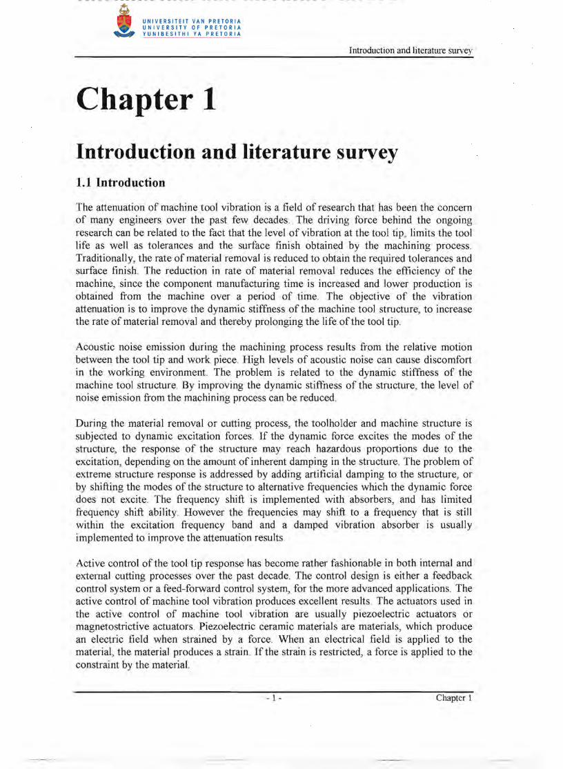
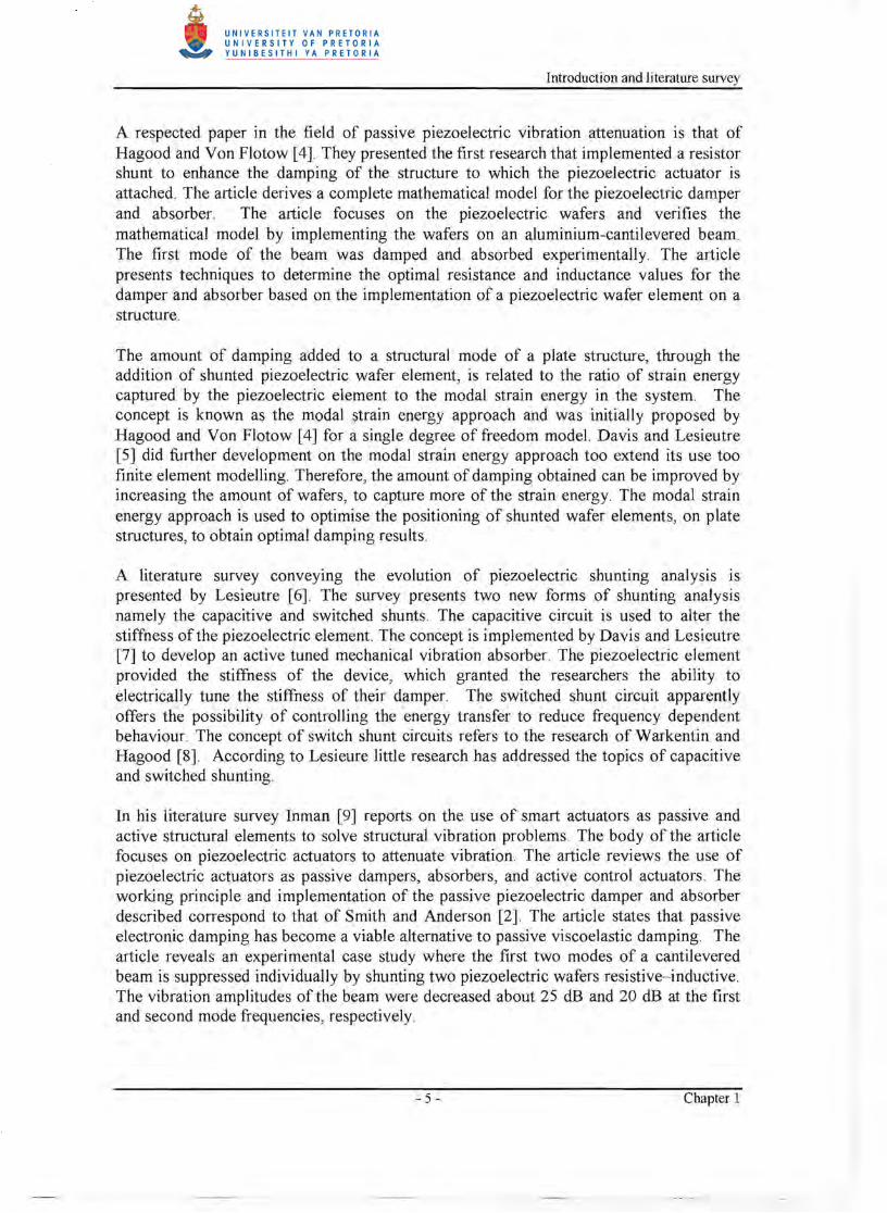
Chatter is a phenomenon in the machining industry that refers to the instance where the cutting process induces a force onto the structure of the machine tool at a frequency near to or at one of the structural modes of the system. Boring bars are slender cutting tools used in a turning operation on a lathe to create cylindrical inner surfaces. These tools operate with a long overhang when machining long cylindrical pieces, therefore boring bars are prone to resonate at their first modes during the machining process. Increasing the stiffness or the damping factor of the boring bar can reduce the chatter. Browning and Woodson [21] proposed a reaction mass actuator to add additional damping to the boring bar as an alternative to active control, which is a cost intensive-solution to the problem. The reaction mass actuator consists of a piezoelectric stack actuator, a mass, a return spring and a hinge. The reaction mass actuator is attached near the cutting tip of the boring bar to alter the dynamic characteristics of the boring bar. The reaction mass actuator's influence on the boring bar is altered by shunting the piezoelectric stack actuator. The piezoelectric stack actuator was shunted with a resistive-inductive or resonant shunt and a negative capacitance shunt. A reduction of 20 dB in the response of the boring bar was obtained by implementing the reaction mass actuator with the negative capacitance shunt, and a 14 dB reduction in the response was obtained with the resonant shunt circuit. The negative capacitance circuit consists of an operational amplifier, a capacitor, and a few resistors. The operational amplifier requires an external electrical power supply, therefore the circuit is referred to as being semi-active. A conceptual drawing of the reaction mass actuator is shown in figure 1.1.
-7- Chapter 1
Introduction and literatme survey
Boring bar tool tip
Figure 1.1 Piezoelectric reaction mass actuator
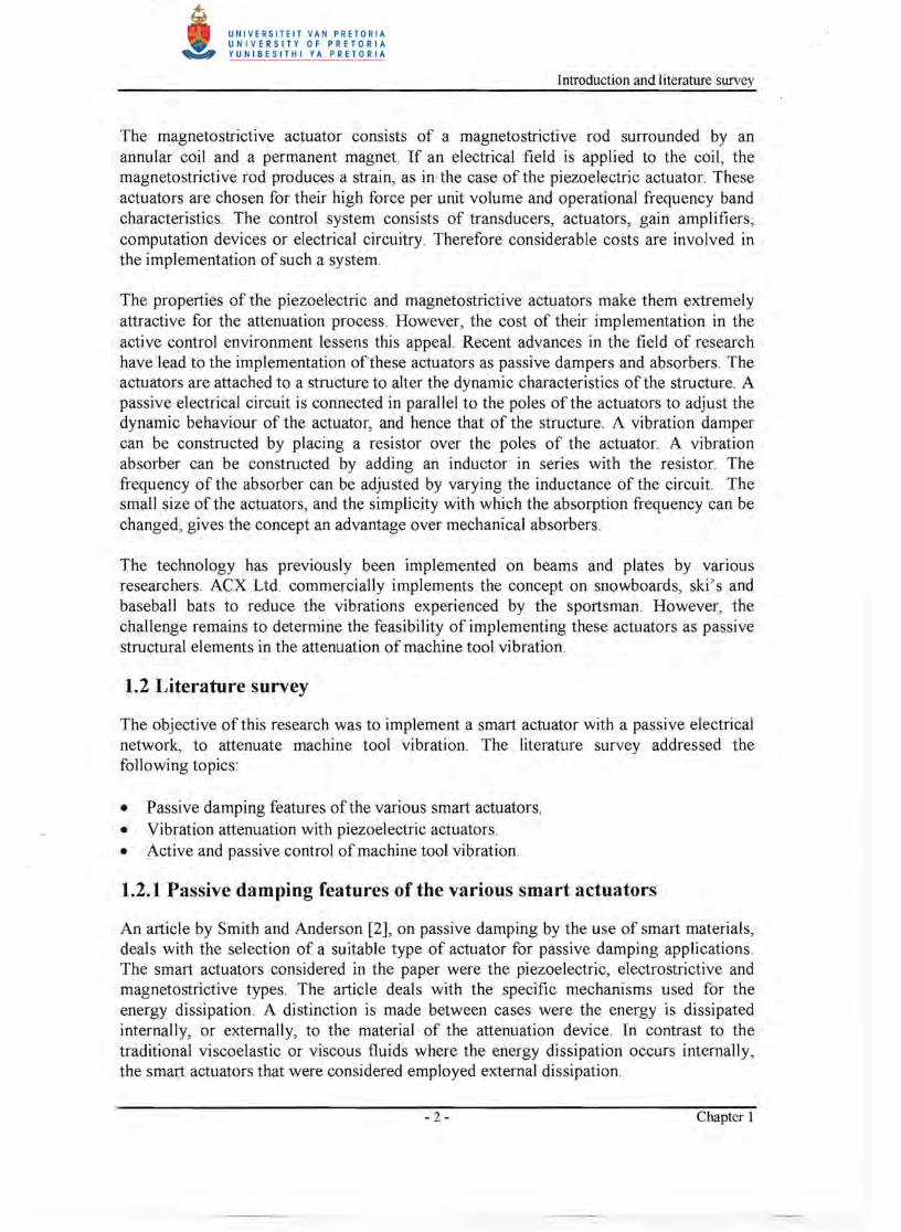
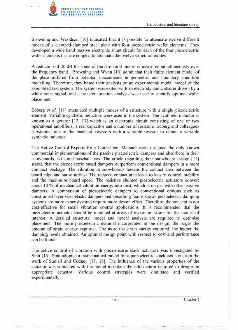
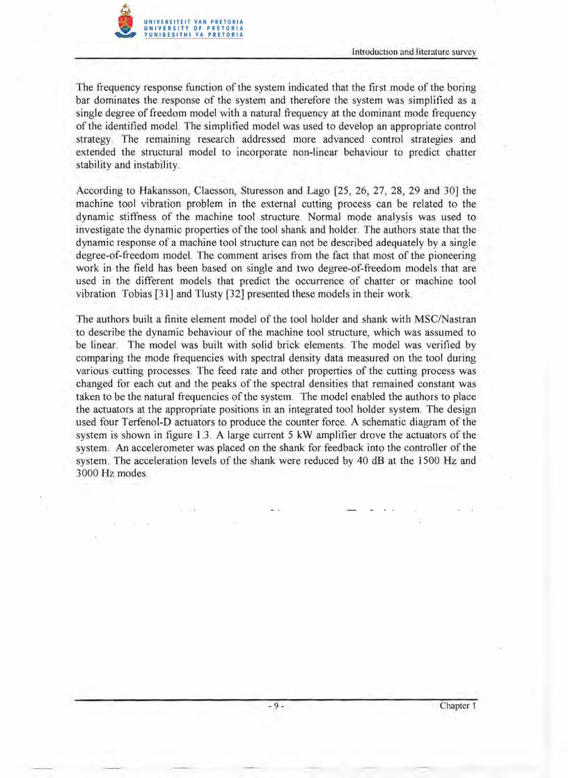
Pratt and Nayfeh [22, 23, and 24] have researched the active control of boring bar chatter. The objective of their research was to increase the stability envelope of the boring bar by implementing active control. They implemented two Terfenol-D actuators to exert the control forces at the base of the boring bar near its attachment, to counteract the unwanted vibration. The actuators are mounted in a plane perpendicular to the feed direction of the lathe. Figure 1.2 presents a schematic diagram of the system.
Terfenol-D actuator
~ Lathe
Figure 1.2 Active boring bar control system [22}
The system utilises two actuators in the transverse directions since chatter can occur in both the directions. Pratt and Nayfeh applied an experimental system identification technique to develop a reduced order model for the structural dynamics of the resulting smart machine tool system. The transfer function is determined from the voltage input of the actuator to the voltage output of the accelerometer. The vertical and horizontal control loops are orthogonal to each other and the authors assumed that no coupling exists in the absence of a cutting force . The system identification was conducted by exciting the Terfenol-D actuator with a random voltage signal and measuring the accelerometer response voltage. The amplifier gain was set at mid range to ignore the effects of system saturation. The data was used to identify a linear system model.
- 8 - Chapter I
Introduction and literature survey
The frequency response function of the system indicated that the first mode of the boring bar dominates the response of the system and therefore the system was simplified as a single degree of freedom model with a natural frequency at the dominant mode frequency of the identified model. The simplified model was used to develop an appropriate control strategy . The remaining research addressed more advanced control strategies and extended the structural model to incorporate non-linear behaviour to predict chatter stability and instability.
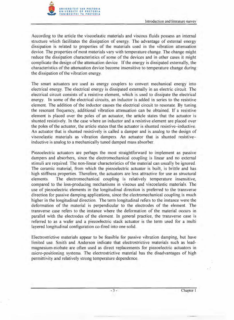
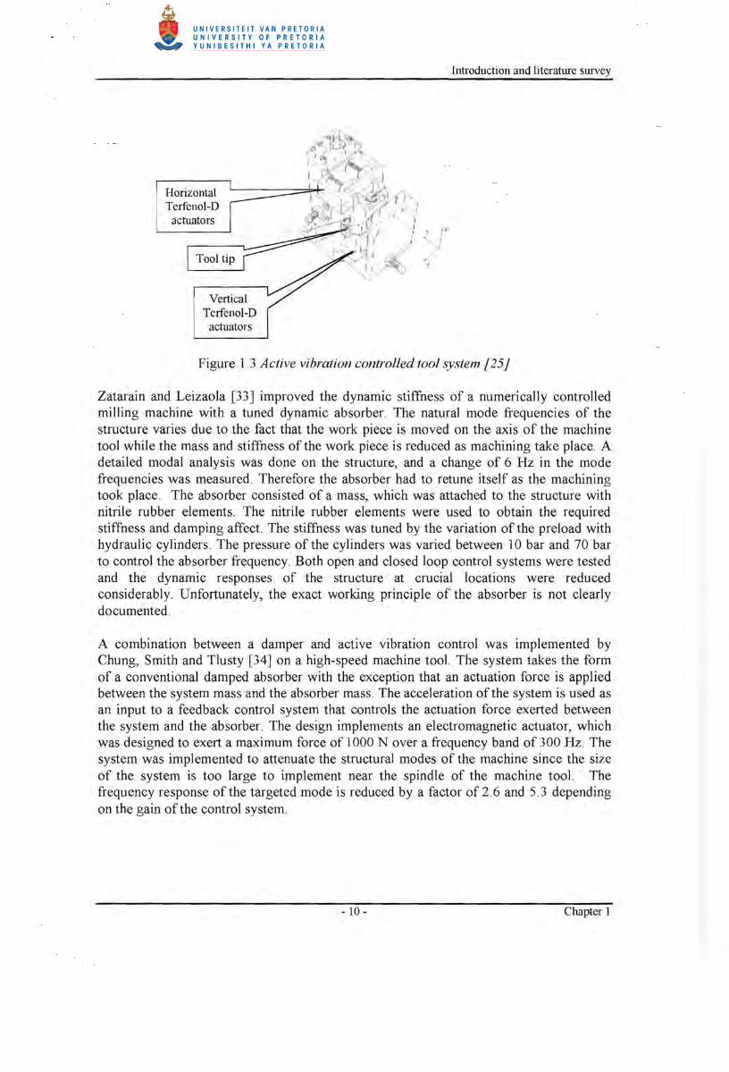
According to Hakansson, Claesson, Sturesson and Lago [25, 26, 27, 28, 29 and 30] the machine tool vibration problem in the external cutting process can be related to the dynamic stiffness of the machine tool structure. Normal mode analysis was used to investigate the dynamic properties of the tool shank and holder. The authors state that the dynamic response of a machine tool structure can not be described adequately by a single degree-of-freedom model. The comment arises from the fact that most of the pioneering work in the field has been based on single and two degree-of-freedom models that are used in the different models that predict the occurrence of chatter or machine tool vibration. Tobias [31] and Tlusty [32] presented these models in their work.
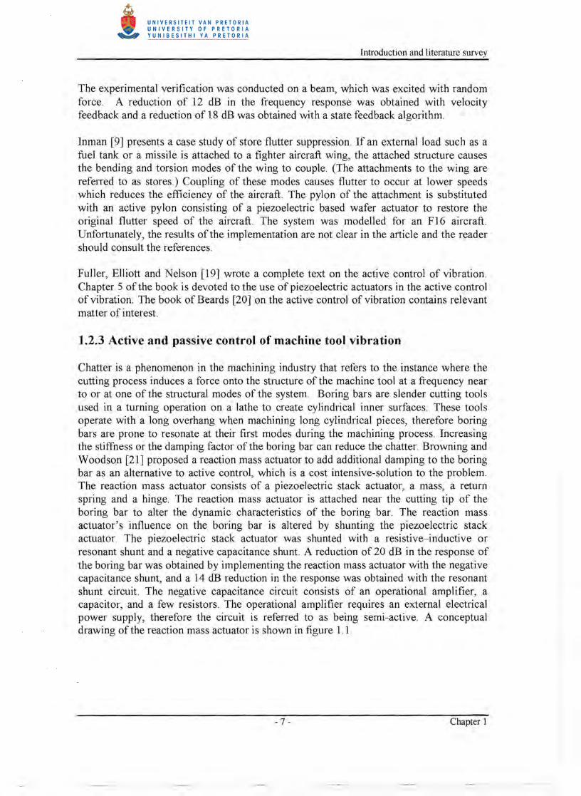
The authors built a finite element model of the tool holder and shank with MSClNastran to describe the dynamic behaviour of the machine tool structure, which was assumed to be linear. The model was built with solid brick elements. The model was verified by comparing the mode frequencies with spectral density data measured on the tool during various cutting processes. The feed rate and other properties of the cutting process was changed for each cut and the peaks of the spectral densities that remained constant was taken to be the natural frequencies of the system. The model enabled the authors to place the actuators at the appropriate positions in an integrated tool holder system. The design used four Terfenol-D actuators to produce the counter force . A schematic diagram of the system is shown in figure 1.3. A large current 5 kW amplifier drove the actuators of the system. An accelerometer was placed on the shank for feedback into the controller of the system. The acceleration levels of the shank were reduced by 40 dB at the 1500 Hz and 3000 Hz modes.
- 9 - Chapter 1
Introduction and literature survey
Horizontal Terfenol-D
actuators
Vertical Terfenol-D
actuators
.. 1 .1
.' x I I "" I
.J
Figure 1 J Active vibration controlled tool system [25J
Zatarain and Leizaola [33] improved the dynamic stiffness of a numerically controlled milling machine with a tuned dynamic absorber. The natural mode frequencies of the structure varies due to the fact that the work piece is moved on the axis of the machine tool while the mass and stiffness of the work piece is reduced as machining take place. A detailed modal analysis was done on the structure, and a change of 6 Hz in the mode frequencies was measured. Therefore the absorber had to retune itself as the machining took place. The absorber consisted of a mass, which was attached to the structure with nitrile rubber elements. The nitrile rubber elements were used to obtain the required stiffness and damping affect. The stiffness was tuned by the variation of the preload with hydraulic cylinders. The pressure of the cylinders was varied between lObar and 70 bar to control the absorber frequency. Both open and closed loop control systems were tested and the dynamic responses of the structure at crucial locations were reduced considerably. Unfortunately, the exact working principle of the absorber is not clearly documented.
A combination between a damper and active vibration control was implemented by Chung, Smith and Tlusty [34] on a high-speed machine tool. The system takes the form of a conventional damped absorber with the exception that an actuation force is applied between the system mass and the absorber mass. The acceleration of the system is used as an input to a feedback control system that controls the actuation force exerted between the system and the absorber. The design implements an electromagnetic actuator, which was designed to exert a maximum force of 1000 N over a frequency band of 300 Hz. The system was implemented to attenuate the structural modes of the machine since the size of the system is too large to implement near the spindle of the machine tool. The frequency response of the targeted mode is reduced by a factor of 2 6 and 5.3 depending on the gain of the control system.
- 10- Chapter 1
Introduction and literature survey
In order to control the spindle vibration of a milling machine, it is necessary to implement actuators on the spindle itself. Martinez, Hinnerichs and Redmond [35] implemented imbedded piezoelectric actuators in a beam that was used as a surrogate machine tool structure. The objective of their study was to determine optimal actuator positions for the active control of the spindle vibration. The authors state that improved methods are required for incorporating smart material actuators in cutting tools without a loss of static stiffness, before active control systems can be implemented on a milling machine spindle.
Riehle and Brown [36] developed a conventional damped absorber for an automatic boring machine to attenuate the first bending mode of the spindle at 300 Hz. The boring machine was used to machine aluminium covers. The components required a surface finish of 50/lin and values of over a hundred were obtained without the damped absorber. A viscoelastic material element was used for the damping and spring stiffness of the damper. The article contains information on the appropriate selection of the geometry and material for the application. The damper was mounted on the spindle and the surface finish was improved to 36 /lin.
1.3 Research objectives
The focus of the research was to attenuate the structural modes of the machine tool. However, it is acknowledged that the component, that is being machined, influences the vibration levels experienced during machining. The attenuation of the vibration of the machine tool structure is practically feasible. The vibration attenuation of the component that is machined remains a challenge and will not be addressed in this research. The research was conducted on a Cholechester CNC 2000L horizontal lathe fitted with a diplomatic tool changer (TRM120 series 10).
The research of Hakansson, Claesson, Sturesson and Lago [25, 26, 27, 28, 29 and 30] indicated that the vibration levels near the tool tip of a lathe can be reduced considerably by the implementation of an active vibration control system that utilises smart actuators to exert the control forces. The global objective of the research was set to determine whether the passive shunting of the smart actuators could be used to improve the dynamic stiffness of the machine tool structure near the tool tip. The first objective of the literature survey was to establish which type of actuator to use in the application.
The article of Smith and Anderson [2], on passive damping by the use of smart materials, addressed the selection of a suitable type of actuator. A piezoelectric actuator was selected for the application based on the fact that it is less expensive than Terfenol-D actuators, the actuator does not require external stimuli in the shunt and its behaviour can be assumed to be linear.
The work of Browning and Woodson [21] indicated that it is possible to shunt a stack actuator since they implemented a shunted piezoelectric stack actuator in their reaction mass actuator. The detail of the mathematical model of the shunt was not documented in their publication and it did not involve the implementation of the piezoelectric actuator as a discrete damper or absorber.
- 11 - Chapter 1
Introduction and literature survey
Therefore the first objective of this research was to derive and validate a mathematical model to simulate the effect of the shunted piezoelectric stack actuator on a structure.
Insight into the dynamic behaviour of the lathe structure under machining conditions had to be obtained in order to implement the vibration attenuation device. Therefore the operational deflection shapes of the lathe structure should be measured under machining conditions, in accordance with the technique proposed by D0ssing et at. [1]. The dynamic characteristics of the lathe structure had to be determined though experimental modal analysis to verify the behaviour of the structure under machining conditions. The two tests should yield the necessary information to understand the behaviour of the structure and to build a mathematical model of the structure for simulation purposes.
The dynamic input force on to the structure should be determined under machining conditions, in order to construct a mathematical simulation of the machining process on the lathe. The mathematical simulation of the machining process can be used to investigate the influence of the absorber on the machine tool structure in a repeatable environment.
The piezoelectric absorber should be implemented on the lathe to verify the mathematical modelling.
1.4 Document overview
The mathematical models of the piezoelectric damper and absorber are derived in chapter 2. The chapter presents various simulations, which indicate the influence of the model parameters on the dynamic stiffness of the structure. The experimental verification of the mathematical model on an aluminium beam is documented.
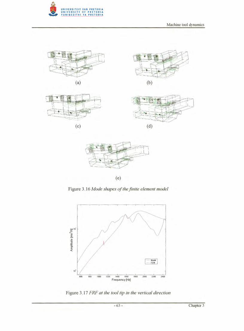
The operational deflection shapes of the lathe as well as the experimental modal analysis results are documented in chapter 3.
The process of estimating the dynamic force that is exerted onto the tool tip is presented in chapter 4.
The experimental implementation of the absorber on the lathe is described in chapter 5. The chapter is further dedicated to the simulation of the absorber implementation on the lathe.
A conclusion to the research is given in chapter 6 as well as recommendations for further research and development.
- 12 - Chapter 1
Mathematical model
Chapter 2
Mathematical model 2.1 Piezoelectric terminology and concepts
At this point it has been made clear that a piezoelectric element deforms when an electrical field is placed over the element. The direction of the electrical field is determined by the placement of the electrodes on the element. The direction in which the electrical field is applied is referred to as the poling direction. It is evident that multiple poling directions are possible in an element. The electrical field has maximum effect in the poling direction but also influences the behaviour of the element in the other directions. To account forthe effects of various poling directions, the constitutive relation for the piezoelectric element is written in a matrix format. The format resembles the use of the material compliance in the field of non-isotropic material modelling. The material properties in this case are not determined by, for example, the material lay-up, but rather the electrical field lay-up on the element. The number of electrical fields and the directions, in which they are applied, are determined by the application.
The constitutive relations and conventions for piezoelectric elements are applied in the same way for a damped vibration absorber as for an actuator. The fact that the material is strained by an applied stress to produce an electrical field does not change the use of the constitutive relation and its convention.
Damped vibration absorbers are based on a uniaxial loading case where the piezoelectric element is subjected to a shear or a normal stress and only one pair of electrodes is present to provide an external electric field. The literature refers to two modes of operation. The longitudinal case where the stress is applied in the electrical field development direction and the transverse case where the directions differ.
2.2 Specification for the mathematical model
The model originates from the work of Hagood and Von Flotow [4]. They derived and verified a single layered transverse case model for a shunted piezoelectric absorber on a cantilevered aluminium beam.
A piezoelectric stack actuator is a multi-layered longitudinal configuration. According to Hagood and Von Flotow [4] the longitudinal configuration of the piezoelectric is more effective than that of the transverse configuration, when implemented as a damped absorber. The higher effectiveness is contributed to the fact that the direction of poling and deformation of the piezoelectric material coincide.
- 13 - Chapter 2
Mathematical model
The multiple layers are introduced to improve the attenuation device's ability to convert mechanical deformation into electrical energy, as well as to increase the capacitance value of the piezoelectric actuator. The relevance of the capacitance value will be dealt with further in section 2.4. The objective was to derive a mathematical damped absorber model for a multi-layered longitudinal piezoelectric actuator (Stack actuator). The model was validated by experimental procedure.
2.3 Derivation of the mathematical model
The constitutive relation for the material constants of a linear three-dimensional piezoelectric solid in accordance with reference [4] is presented by equation (2.1).
(2.1)
with:
D: Electrical displacements (charge/area). [; : Dielectric constant. E: Electrical field in the material (volt/meter). s: Compliance. S: Material engineering strain. d: Piezoelectric constant. T: Material stress (force/area).
The lowercase entries are matrices defining the material properties of the non-isotropic material. The uppercase entries denote the variable vectors. The superscripts on the material property denote the mechanical or electrical boundary condition under which the constants are valid and the subscript t denotes the conventional matrix transpose.
According to Hagood and Von Flotow [5], the material property matrices in equation (2.1) can be simplified to single value material properties when the piezoelectric element is loaded uniaxially with a normal stress and only one pair of electrodes is present on the element to develop the external electrical field in the same direction.
The piezoelectric properties for the longitudinal application are denoted by a subscript '33', which indicates that, the direction of loading and electrical field development is in the '3' direction in accordance with piezoelectric convention.
(2.2)
The entries into equation (2.2) are scalars.
To incorporate traditional concepts, such as admittance and impedance, into the shunting analysis, a change of variables are required. The definitions for voltage and current are used for this purpose and are defined by equations (2.3) and (2.4) .
- 14 - Chapter 2

Mathematical model
1= f~D.da (2.3) A Ot
L
V= fE.dx (2.4) o
The assumption is made that the field within and the electrical displacement on the surface are uniform for the piezoelectric material. The linear relationships can be defined in the Laplace domain by equations (2.5) and (2.6).
I(s)=sA·D(s) (2.5)
V(s) = L· E(s) (2.6)
with: L: Length of the material in the poling directions. A: Area perpendicular to the direction of poling. s: Laplace parameter.
By taking the Laplace transform of equation 2.2 and using equations 2.5 and 2.6 to eliminate E and D, the constitutive relation for a piezoelectric in terms of the external current input and applied voltage is obtained.
(2.7)
The upper left partition of the constitutive relation matrix can be defined as the capacitance between the surfaces that are perpendicular to the poling direction. Therefore the constitutive relation can be written as.
(2.8)
The open circuit admittance of the piezoelectric due to the inherent capacitance with free boundary conditions is defined as.
For shunted piezoelectric applications, a passive electrical circuit is connected in parallel with the surface electrodes of the piezoelectric.
- 15 - Chapter 2
Mathematical model
The circuit is in parallel with the inherent capacitance of the piezoelectric. The admittance in parallel adds and therefore the constitutive relation for a shunted piezoelectric can be written as.
yEL =yD +ySU (2.10)
(2.11)
with: yD : Open circuit electrical admittance of the piezoelectric. ySU : Shunting admittance of the piezoelectric. yEL : Electrical admittance of the shunted piezoelectric.
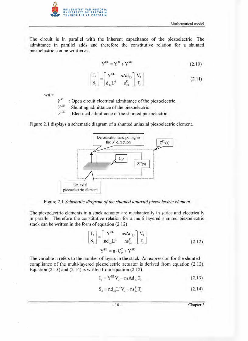
Figure 2.1 displays a schematic diagram of a shunted uniaxial piezoelectric element.
Defonnation and poling in the 3' direction ~
H ••••••••• •••••••••• ~
Uniaxial piezoelectric element
Figure 2.1 Schematic diagram ofthe shunted uniaxial piezoelectric element
The piezoelectric elements in a stack actuator are mechanically in series and electrically in parallel. Therefore the constitutive relation for a multi layered shunted piezoelectric stack can be written in the form of equation (2.12).
(2.12)
yEL =n . CT + ySUp
The variable n refers to the number of layers in the stack. An expression for the shunted compliance of the multi-layered piezoelectric actuator is derived from equation (2.12) . Equation (2.13) and (2.14) is written from equation (2.12).
(2.13)
(2.14)
- 16 - Chapter 2
Mathematical model
Equation (2.13) can be written as an expression for the applied voltage and substituted in to equation (2.14) to obtain equation (2.16)
(2.15)
with:
Z EL : Electrical impedance, equal to the inverse of the electrical admittance.
(2.16)
From equation (2.16) the shunted piezoelectric compliance can be defined from the terms in brackets that relates the material strain to the applied stress.
(2 .17)
The relation between applied force and displacement, for the uniaxial loading case of the stack actuator, is expressed in equation (2.18).
(2.18)
By altering the electrical impedance term, the passive characteristics of the stack actuator is altered. The process of altering the passive characteristics of the actuator has been referred to as shunting. As indicated in chapter 1, there are two types of electrical networks that are used for shunting the actuator, the first of which is resistive shunting where a resistor is placed in parallel over the actuator poles, and the second where a inductor is added in series with the resistance. The second shunt is referred to as a resonant shunting since the circuit resonates. The expression of electrical impedance for the resistively shunted actuator is expressed by equation (2.19) and the expression for the resonant shunted actuator is expressed by equation (2 .20).
ZEL = R (2.19) RnC!s + I
ZEL = Ljs+R (2.20)L j nC!s2 +RnC!s + 1
with: R: Resistance of the shunt circuit Li : Inductance of the shunt circuit
- 17 - Chapter 2
Mathematical model
The actuator is implemented as a damper or a damped absorber on a structure through the use of the relation between the applied force and displacement as a transfer function in a feedback loop to the force input of the structure model. The transfer function is obtained by substituting either equation (2.19) or (2.20) into equation (2.18) and manipulating to obtain equation (2.21) for the resistive shunt case or equation (2.22) for the resonant shunt case.
KME = {nAC~R}s + A (2.21) 33 { 3L ECTR 3d2 AR} { 2 E}n S33 P - n 33 s + n LS33
KME = {nAC~LJS2 +{nAC~R}s+A (2.22) 33 {n 3Ls;3C~Li - n3d;3ALJs2 + {n3Ls;3C!R - n3d;3 AR}s + {n 2Ls;J
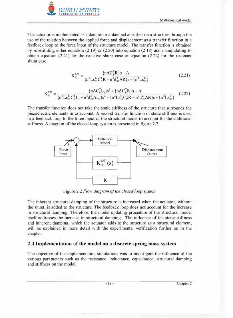
The transfer function does not take the static stiffness of the structure that surrounds the piezoelectric elements in to account. A second transfer function of static stiffness is used in a feedback loop to the force input of the structural model to account for the additional stiffness. A diagram of the closed-loop system is presented in figure 2.2.
Force
Structural Model
Displacement Inout Outout
K
Figure 2.2 Flow diagram a/the closed loop system
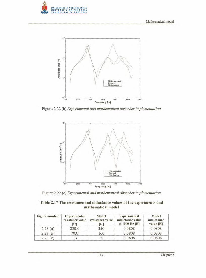
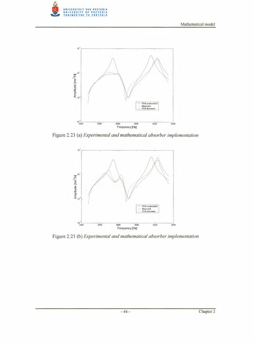
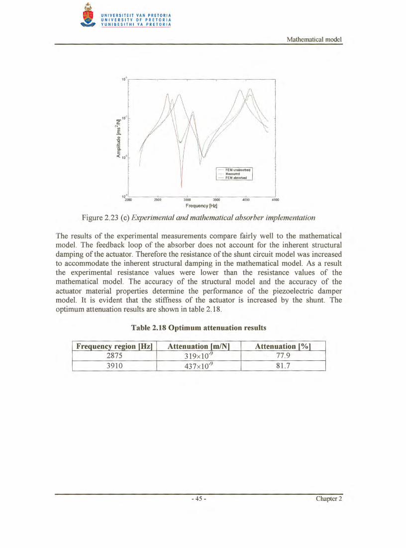
The inherent structural damping of the structure is increased when the actuator, without the shunt, is added to the structure. The feedback loop does not account for the increase in structural damping. Therefore, the model updating procedure of the structural model itself addresses the increase in structural damping. The influence of the static stiffness and inherent damping, which the actuator adds to the structure as a structural element, will be explained in more detail with the experimental verification further on in the chapter.
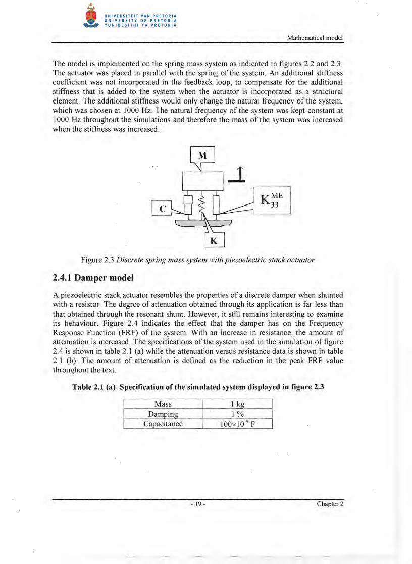
2.4 Implementation of the model on a discrete spring mass system
The objective of the implementation simulations was to investigate the influence of the various parameters such as the resistance, inductance, capacitance, structural damping and stiffness on the model.
-18 - Chapter 2
Mathematical model
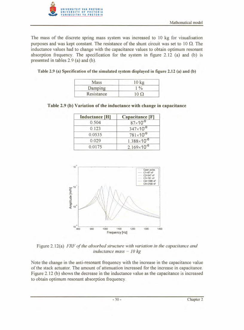
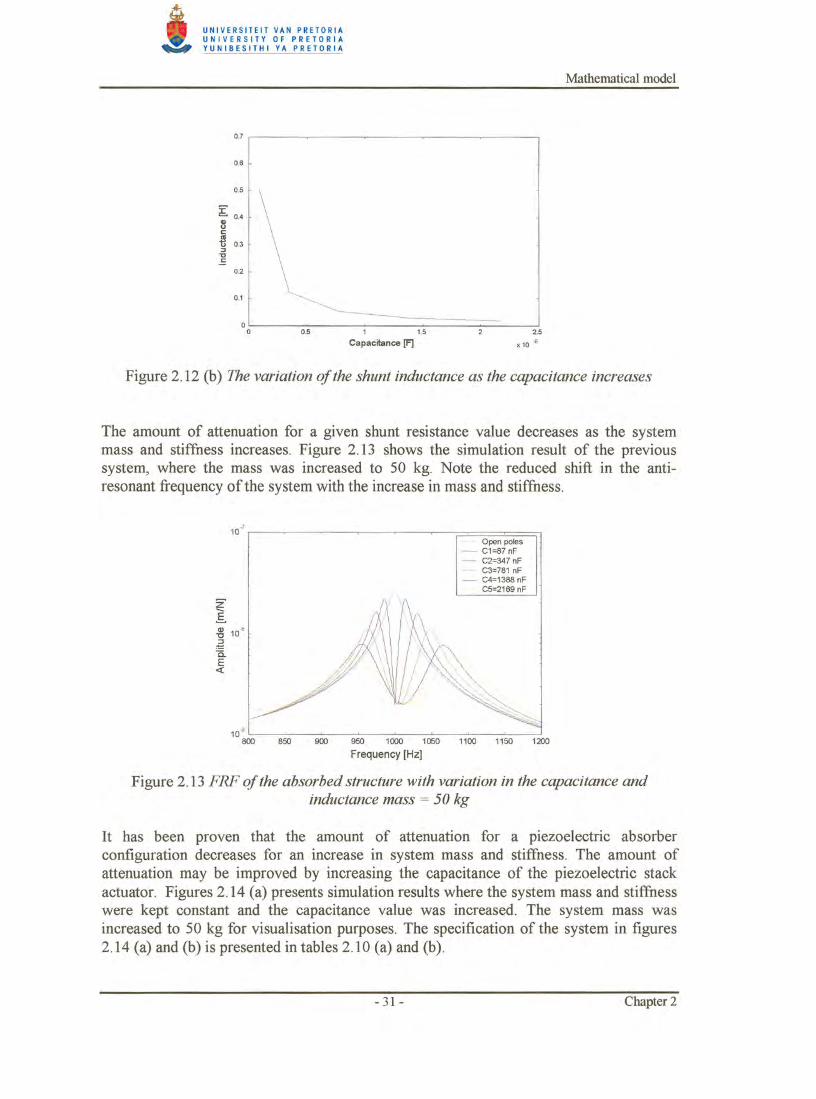
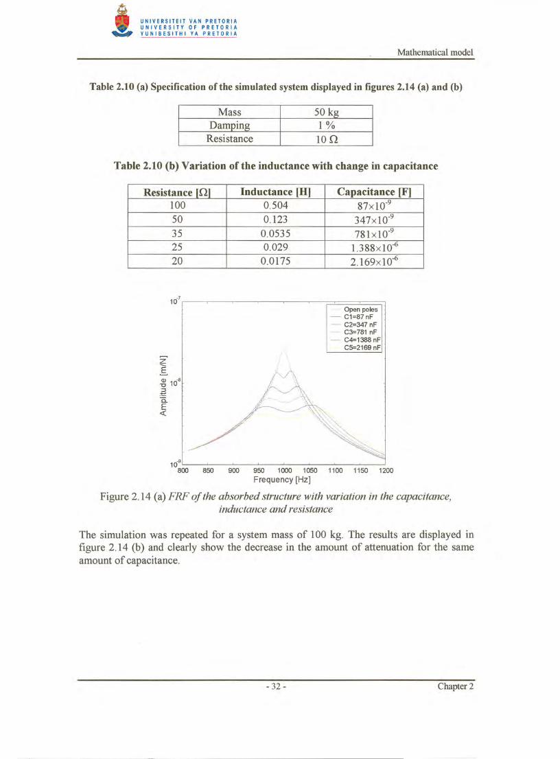
The model is implemented on the spring mass system as indicated in figures 2.2 and 2.3. The actuator was placed in parallel with the spring of the system. An additional stiffness coefficient was not incorporated in the feedback loop, to compensate for the additional stiffness that is added to the system when the actuator is incorporated as a structural element. The additional stiffness would only change the natural frequency of the system, which was chosen at 1000 Hz. The natural frequency of the system was kept constant at 1000 Hz throughout the simulations and therefore the mass of the system was increased when the stiffness was increased .
K~
Figure 2.3 Discrete spring mass system with piezoelectric stack actuator
2.4.1 Damper model
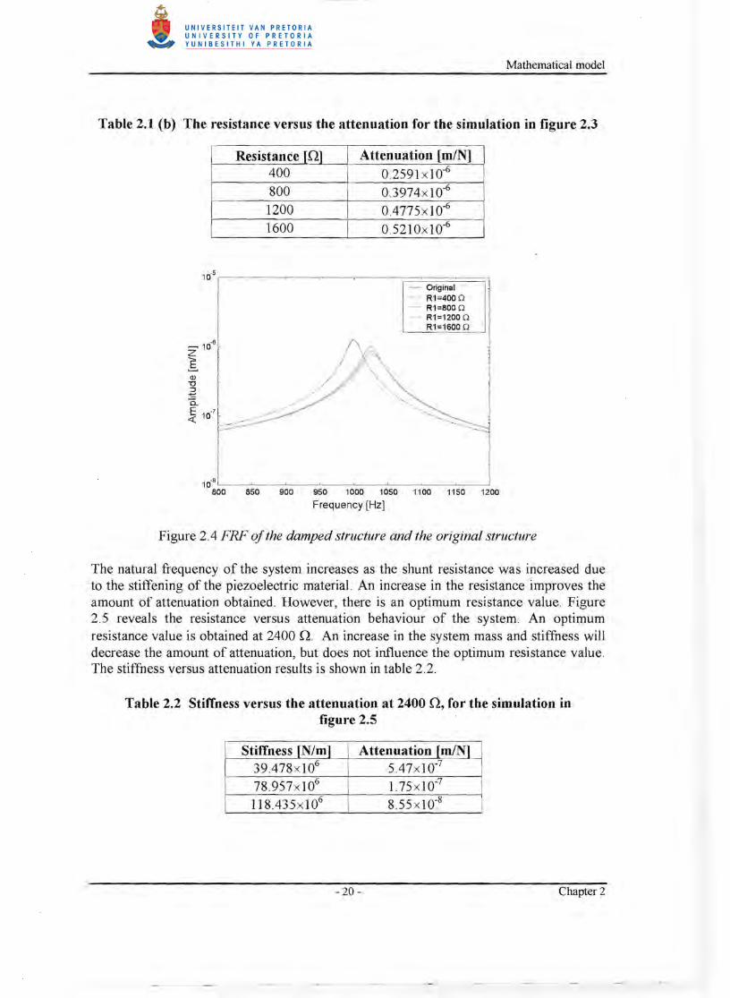
A piezoelectric stack actuator resembles the properties of a discrete damper when shunted with a resistor. The degree of attenuation obtained through its application is far less than that obtained through the resonant shunt. However, it still remains interesting to examine its behaviour. Figure 2.4 indicates the effect that the damper has on the Frequency Response Function (FRF) of the system. With an increase in resistance, the amount of attenuation is increased. The specifications of the system used in the simulation of figure 2.4 is shown in table 2.1 (a) while the attenuation versus resistance data is shown in table 2.1 (b) . The amount of attenuation is defined as the reduction in the peak FRF value throughout the text.
Table 2.1 (a) Specification of the simulated system displayed in figure 2.3
Mass 1kg Damping 1%
Capacitance 100xlO9 F
- 19 - Chapter 2
Mathematical model
Table 2.1 (b) The resistance versus the attenuation for the simulation in figure 2.3
Resistance [0] Attenuation [mIN] 400 0.2591 x l0-6
800 0.3974x l0-6
1200 0.4775x 1 0-6
1600 0.5210xlO-6
10. 5 t--,----,-----.---,.----.--;=======;_J
- Original - R1=400Q - R1=BOOQ - R1=1200Q
R1=1600 Q
10.8 '---'----'--~--~--'------'------'----' BOO 850 900 · 950 1000 1050 1100 1150 1200
Frequency [Hz]
Figure 2.4 FRF ofthe damped structure and the original structure
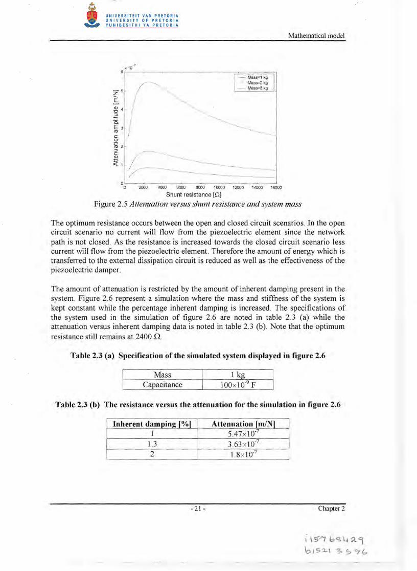
The natural frequency of the system increases as the shunt resistance was increased due to the stiffening of the piezoelectric material. An increase in the resistance improves the amount of attenuation obtained. However, there is an optimum resistance value. Figure 2.5 reveals the resistance versus attenuation behaviour of the system. An optimum resistance value is obtained at 2400 O. An increase in the system mass and stiffness will decrease the amount of attenuation, but does not influence the optimum resistance value. The stiffness versus attenuation results is shown in table 2.2.
Table 2.2 Stiffness versus the attenuation at 2400 0, for the simulation in figure 2.5
Stiffness [N/m] Attenuation [mIN] 39.478x l06 5.47x l0-7
78.957x 10⁶ 1.75 x l0-7
118.435x I06 8.55 x 1 0-8
- 20- Chapter 2
Mathematical model
.7 X 10
6 r---~--~--~--~----~~~==~===0 - Mas5"'1 kg - Mas5"'2kg - Mas5"'3kg
Z5 E ~ 4
.-E 0.. E 3 co c: o ~2 ~ c: Q)
t::«1
O L---~--~--~--~----~--~--~--~ o 2000 4000 6000 8000 10000 12000 14000 16000
Shunt resistance [Q]
Figure 2.5 Attenuation versus shunt resistance and system mass
The optimum resistance occurs between the open and closed circuit scenarios. In the open circuit scenario no current will flow from the piezoelectric element since the network path is not closed. As the resistance is increased towards the closed circuit scenario less current will flow from the piezoelectric element. Therefore the amount of energy which is transferred to the external dissipation circuit is reduced as well as the effectiveness of the piezoelectric damper.
The amount of attenuation is restricted by the amount of inherent damping present in the system. Figure 2.6 represent a simulation where the mass and stiffness of the system is kept constant while the percentage inherent damping is increased. The specifications of the system used in the simulation of figure 2.6 are noted in table 2.3 (a) while the attenuation versus inherent damping data is noted in table 2.3 (b) . Note that the optimum resistance still remains at 2400 n.
Table 2.3 (a) Specification of the simulated system displayed in figure 2.6
Mass 1 kg Capacitance 100xlO-9 F
Table 2.3 (b) The resistance versus the attenuation for the simulation in figure 2.6
Inherent damping r%1 Attenuation rmIN1 1 5.47xlO-7
1.3 3.63 x lO-7
2 1.8xlO-7
- 21 - Chapter 2
i \S-/f bq,~?'t
to \'.7:2-\ !:. So '71::..
Mathematical model
X 10 .7
Z
1
/
-5
/ /- -. c o ~ 2 :::l
Q)
~1 C
6 r---~------~--------~~~==~==~ - Damping=1 %
Damping=1.3 % - Damping=2 %
.
~ //
/~ ------------------l
o L-----~----~--~-~--_~ __~__~ o 2000 4000 6000 8000 10000 12000 14000 16000
Shunt resistance [OJ
Figure 2.6 Attenuation versus shunt resistance and system damping
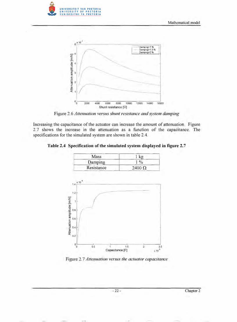
Increasing the capacitance of the actuator can increase the amount of attenuation. Figure 2.7 shows the increase in the attenuation as a function of the capacitance. The specifications for the simulated system are shown in table 2.4.
Table 2.4 Specification of the simulated system displayed in figure 2.7
Mass 1 kg Damping 1%
Resistance 2400.Q
-6 x10
1.4 r----:-----~-----~------------------___,
1.2
Z11
Q)
"0
~ 0.8 a. E ~ 0.6 o
.~
E 0.4 Q)
~ 0.2
oL-----~---~-----~--~~----~ o 0.5 1 1.5 2 2.5
Capacitance [Fj x 10 -6
Figure 2.7 Attenuation versus the actuator capacitance
- 22- Chapter 2
Mathematical model
It is unclear why the curve in figure 2.7 has the peculiar shape. No further attention was given to the shape since better attenuation could be obtained with the piezoelectric absorber. The one prominent aspect shown by the curve is that an increase in the capacitance value increases the amount of attenuation. The cost of the actuator should be taken into account when selecting an optimal capacitance value.
2.4.2 Absorber model
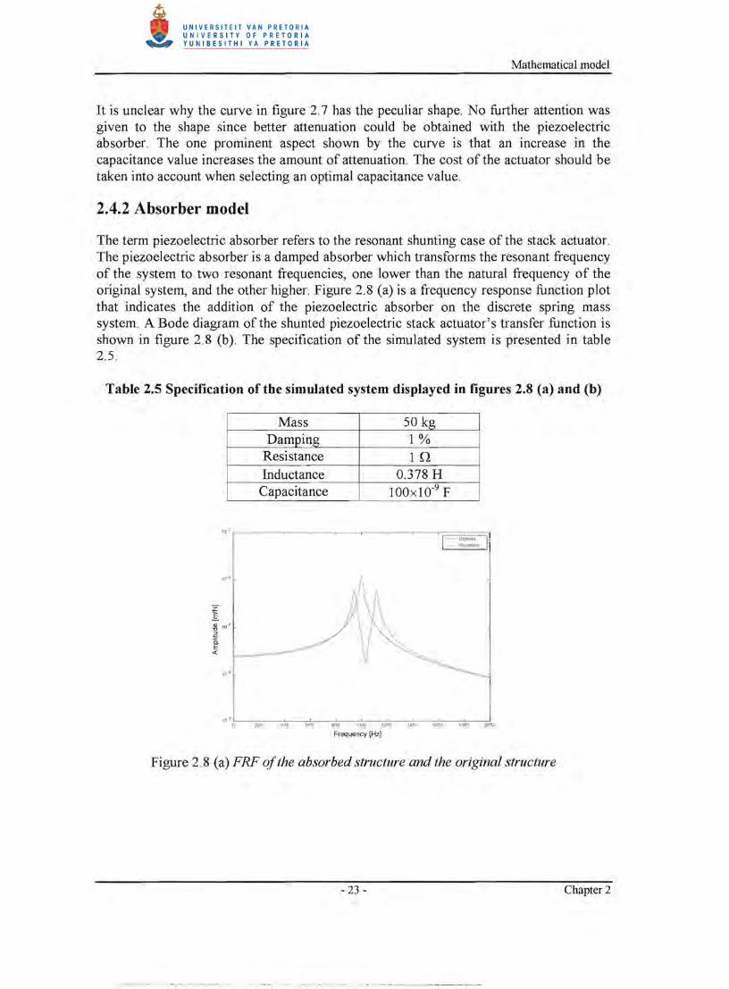
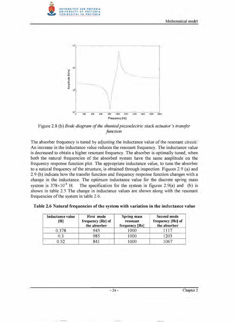
The term piezoelectric absorber refers to the resonant shunting case of the stack actuator. The piezoelectric absorber is a damped absorber which transforms the resonant frequency of the system to two resonant frequencies, one lower than the natural frequency of the original system, and the other higher. Figure 2.8 (a) is a frequency response function plot that indicates the addition of the piezoelectric absorber on the discrete spring mass system. A Bode diagram of the shunted piezoelectric stack actuator's transfer function is shown in figure 2.8 (b). The specification of the simulated system is presented in table 2.5.
Table 2.5 Specification of the simulated system displayed in figures 2.8 (a) and (b)
Mass 50 kg Damping 1%
Resistance In Inductance 0.378 H Capacitance 100x lO-9 F
11i.J o:--::m;;;;---;;!;''''',-----;;:;;---;''''';;;;--:-'.-':rm:---:::''''''::---:-";;;011-,;;!OOO:---;;;,,,oo ?OQII..,. ::---;;;!,Frequency [Hz]
Figure 2.8 (a) FRF ofthe absorbed structure and the original structure
- 23 - Chapter 2
Mathematical model
1 ~L-~~~--~~--~~~--~~__~~ a 200 400 600 800 1000 1200 1400 1600 1800 2000
Frequency [Hz]
Figure 2.8 (b) Bode diagram ofthe shunted piezoelectric stack actuator's transfer function
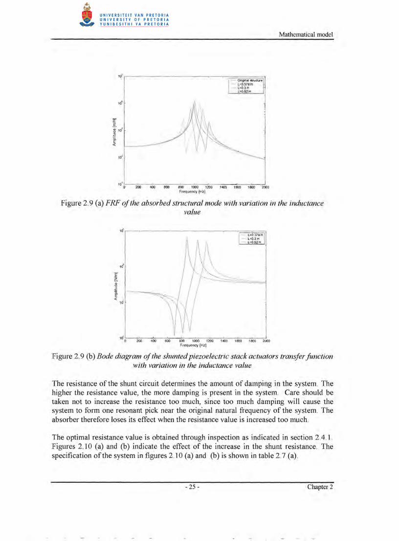
The absorber frequency is tuned by adjusting the inductance value of the resonant circuit. An increase in the inductance value reduces the resonant frequency. The inductance value is decreased to obtain a higher resonant frequency. The absorber is optimally tuned, when both the natural frequencies of the absorbed system have the same amplitude on the frequency response function plot. The appropriate inductance value, to tune the absorber to a natural frequency of the structure, is obtained through inspection. Figures 2.9 (a) and 2. 9 (b) indicate how the transfer function and frequency response function changes with a change in the inductance. The optimum inductance value for the discrete spring mass system is 378x10-3 H. The specification for the system in figures 2.9(a) and (b) is shown in table 2.5 The change in inductance values are shown along with the resonant frequencies of the system in table 2.6.
Table 2.6 Natural frequencies of the system with variation in the inductance value
Inductance value [0]
First mode frequency [Hz] of
the absorber
Spring mass resonant
frequencyJHzl
Second mode frequency [Hz] of
the absorber 0.378 945 1000 1117
0.3 985 1000 1203 0.52 841 1000 1067
- 24- Chapter 2
Mathematical model
10:" O~~ 400 aOO ~ ' ""'" '-=0 '40O-,,-:L60C:-200:---'-=--:::-::---800:---:-!000- 20-:""-~ O -----c,BOc:'::-0:--~2000 Frequency [Hz)
Figure 2.9 (a) FRF ofthe absorbed structural mode with variation in the inductance value
1 if.-~-~---~---~-~-c===~~ -=L=0.378H - L=D.3H
10
E" ~ " .] a. E «
10'
1 & L-~:--~_~_~~
- L=0.52H
__~__~__~_~~ o 200 400 aoo 800 1000 1200 1400 1600 1BOO 2000
Frequency [Hz)
Figure 2.9 (b) Bode diagram ofthe shunted piezoelectric stack actuators transfer function with variation in the inductance value
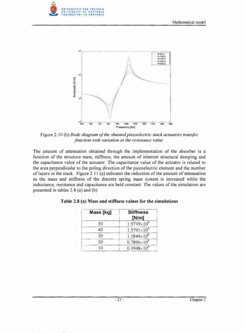
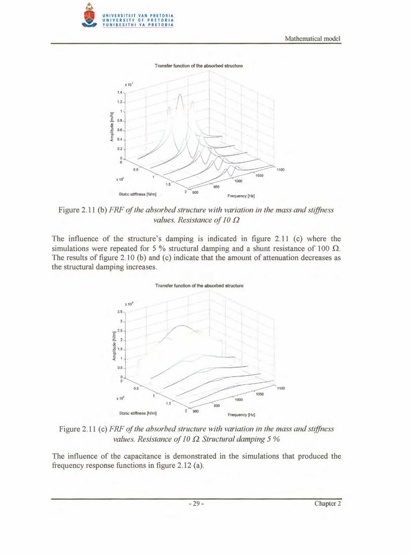
The resistance of the shunt circuit determines the amount of damping in the system. The higher the resistance value, the more damping is present in the system. Care should be taken not to increase the resistance too much, since too much damping will cause the system to form one resonant pick near the original natural frequency of the system. The absorber therefore loses its effect when the resistance value is increased too much.
The optimal resistance value is obtained through inspection as indicated in section 2.4.1 . Figures 2.10 (a) and (b) indicate the effect of the increase in the shunt resistance. The specification of the system in figures 2.10 (a) and (b) is shown in table 2.7 (a) .
- 25 - Chapter 2
Mathematical model
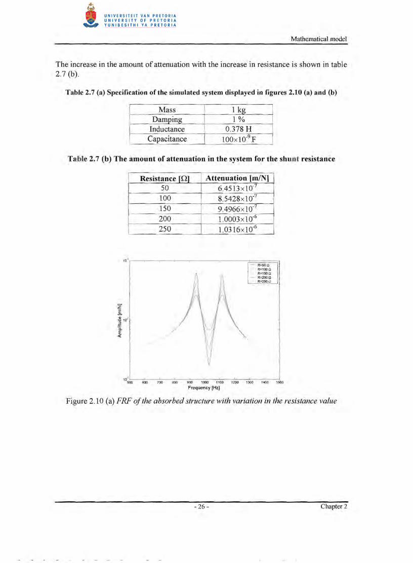
The increase in the amount of attenuation with the increase in resistance is shown in table 2 .7 (b).
Table 2.7 (a) Specification of the simulated system displayed in figures 2.10 (a) and (b)
Mass 1 kg DamjJing 1%
Inductance 0.378 H Capacitance 100x10-9 F
Table 2.7 (b) The amount of attenuation in the system for the shunt resistance
Resistance InJ Attenuation [mIN] 50 6.4513 x 1 0-7
100 8.5428x 10⁻⁷
150 9.4966x lO-7
200 1.0003 x 1 0-6
250 1.0316x10⁻⁶
'O~r-----'---r----'--"'----'----r---"'----;====;"] - R=50 Q - R=100 Q
R<'SO Q - R=200 0
R=2SO Il
10;OO~-6OO:--"":'700 ~ ~--',::,:0 --:-:00--: 2O0 --:-:'::-::- 4O0 ~~ ~-6OO:--"":'900 OO-=- " '::-:: '= -=- ' 3O0 ':-':-=- 'soo Frequency [Hz]
Figure 2 .10 (a) FRF of the absorbed structure with variation in the resistance value
- 26- Chapter 2
Mathematical model
1~~~--~--~--~~--~--~--~~--~ 500 600 700 800 900 1000 1100 1200 1300 1400 1500
Frequency [Hz]
Figure 2.10 (b) Bode diagram of the shunted piezoelectric stack actuators transfer function with variation in the resistance value
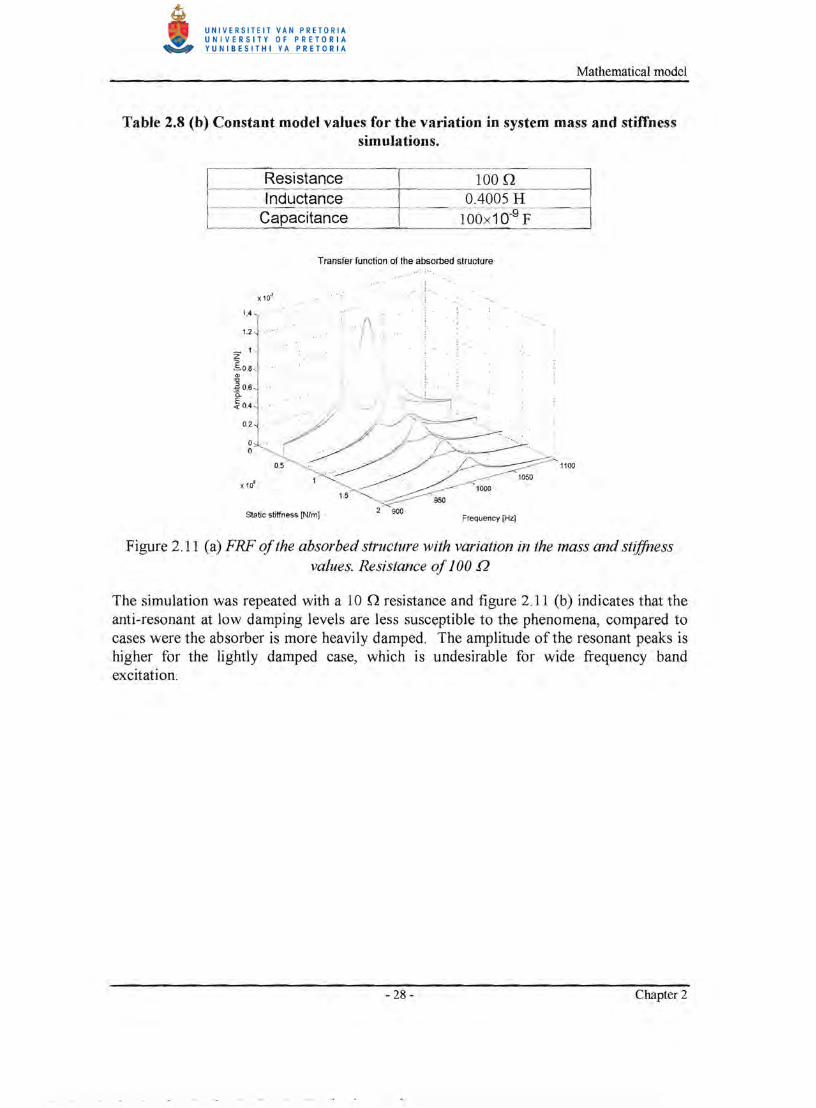
The amount of attenuation obtained through the implementation of the absorber is a function of the structure mass, stiffness, the amount of inherent structural damping and the capacitance value of the actuator. The capacitance value of the actuator is related to the area perpendicular to the poling direction of the piezoelectric element and the number of layers in the stack. Figure 2.11 (a) indicates the reduction of the amount of attenuation as the mass and stiffness of the discrete spring mass system is increased while the inductance, resistance and capacitance are held constant. The values of the simulation are presented in tables 2.8 (a) and (b) .
Table 2.8 (a) Mass and stiffness values for the simulations
Mass [kg] Stiffness [N/ml
50 1.9739x l09
40 1.5791xl09
30 1.1844x 1 09
20 0.7896xl09
10 0.3948x l09
- 27- Chapter 2
Mathematical model
Table 2.8 (b) Constant model values for the variation in system mass and stiffness simulations.
Resistance 100.Q Inductance 0.4005 H
Capacitance 100x10-9 F
Transfer function of the absorbed structure
1.4
1.2 ./\ ~1 ~0.8
'" " ~M , .
!O.4 '-...// ~'
0.2J' .' .~'i //~. '. ."
g , . (~ . . ~... ~ ... .. .
x109 1
1.5
2 900Static stiffness [N/m] Frequency [Hz]
Figure 2.11 (a) FRF ofthe absorbed structure with variation in the mass and st~ffness values. Resistance ofJ00 Q
The simulation was repeated with a 10 .Q resistance and figure 2.11 (b) indicates that the anti-resonant at low damping levels are less susceptible to the phenomena, compared to cases were the absorber is more heavily damped. The amplitude of the resonant peaks is higher for the lightly damped case, which is undesirable for wide frequency band excitation.
/" .. / . 1100
~'.-
- 28 - Chapter 2
Mathematical model
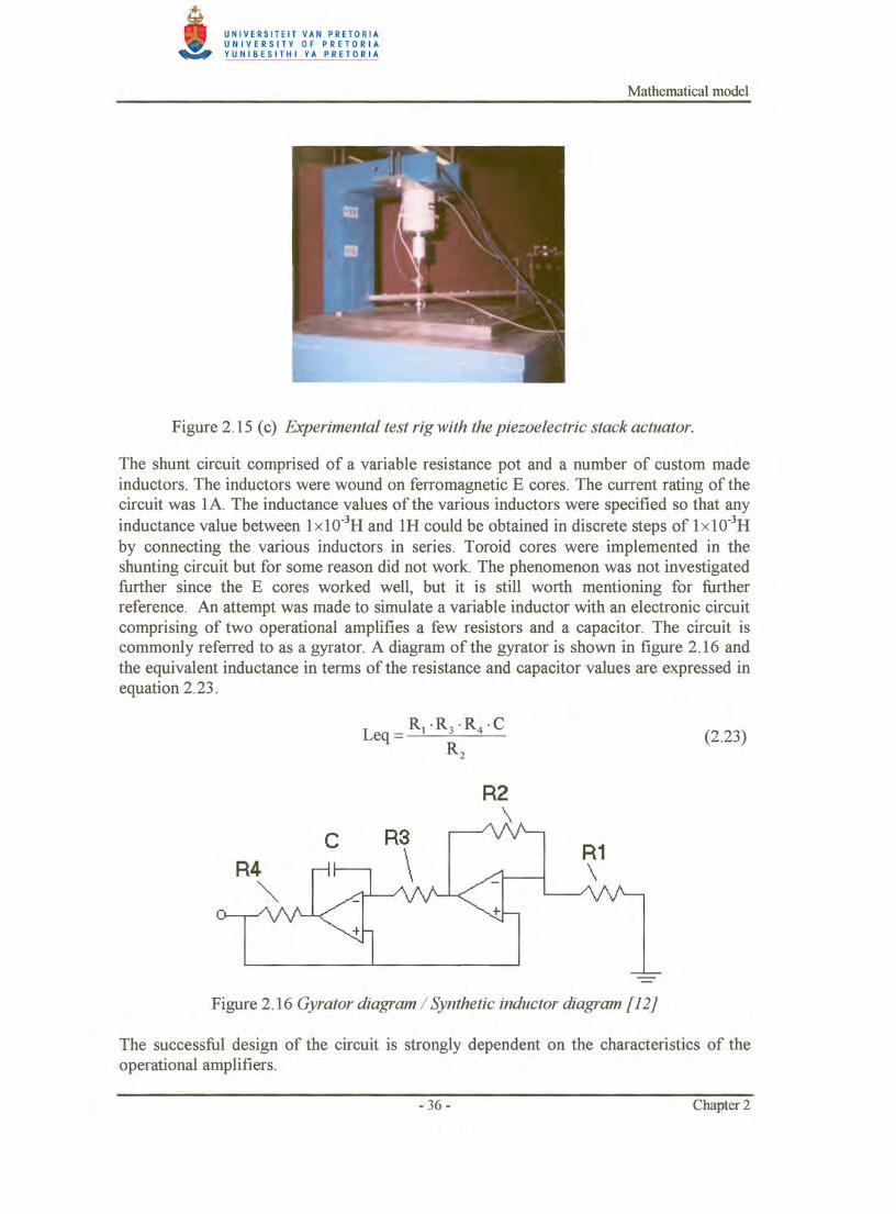
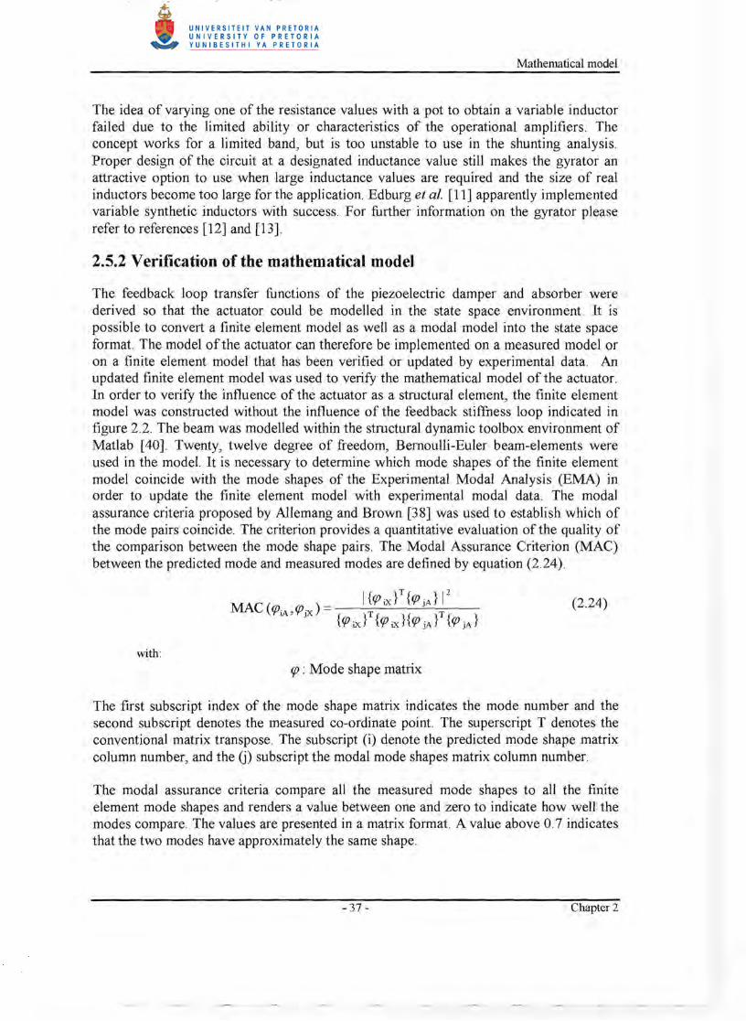
The idea of varying one of the resistance values with a pot to obtain a variable inductor failed due to the limited ability or characteristics of the operational amplifiers. The concept works for a limited band, but is too unstable to use in the shunting analysis. Proper design of the circuit at a designated inductance value still makes the gyrator an attractive option to use when large inductance values are required and the size of real inductors become too large for the application. Edburg et al. [11] apparently implemented variable synthetic inductors with success. For further information on the gyrator please refer to references [12] and [13].
2.5.2 Verification of the mathematical model
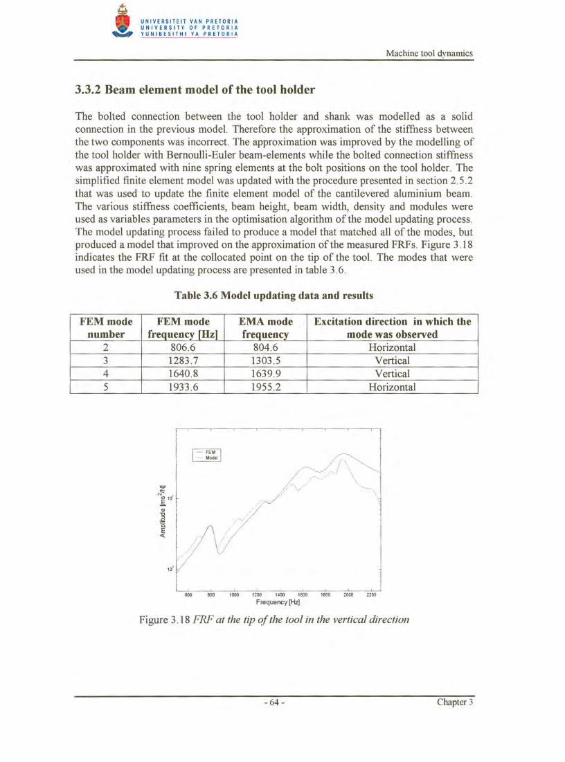
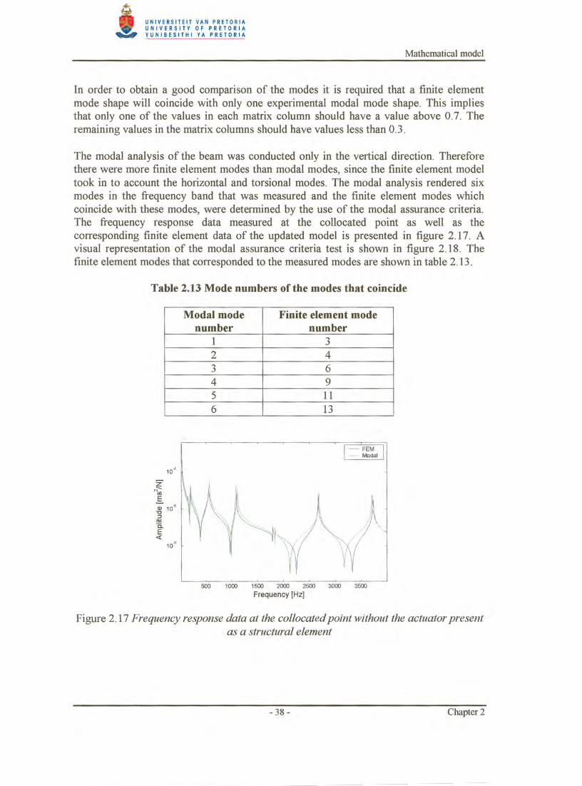
The feedback loop transfer functions of the piezoelectric damper and absorber were derived so that the actuator could be modelled in the state space environment . It is possible to convert a finite element model as well as a modal model into the state space format. The model of the actuator can therefore be implemented on a measured model or on a finite element model that has been verified or updated by experimental data. An updated finite element model was used to verify the mathematical model of the actuator . In order to verify the influence of the actuator as a structural element, the finite element model was constructed without the influence of the feedback stiffness loop indicated in figure 2.2. The beam was modelled within the structural dynamic toolbox environment of Matlab [40]. Twenty, twelve degree of freedom, Bernoulli-Euler beam-elements were used in the model. It is necessary to determine which mode shapes of the finite element model coincide with the mode shapes of the Experimental Modal Analysis (EMA) in order to update the finite element model with experimental modal data. The modal assurance criteria proposed by Allemang and Brown [38] was used to establish which of the mode pairs coincide. The criterion provides a quantitative evaluation of the quality of the comparison between the mode shape pairs. The Modal Assurance Criterion (MAC) between the predicted mode and measured modes are defined by equation (2.24).
(2.24)
with: rp : Mode shape matrix
The first subscript index of the mode shape matrix indicates the mode number and the second subscript denotes the measured co-ordinate point. The superscript T denotes the conventional matrix transpose. The subscript (i) denote the predicted mode shape matrix column number, and the G) subscript the modal mode shapes matrix column number.
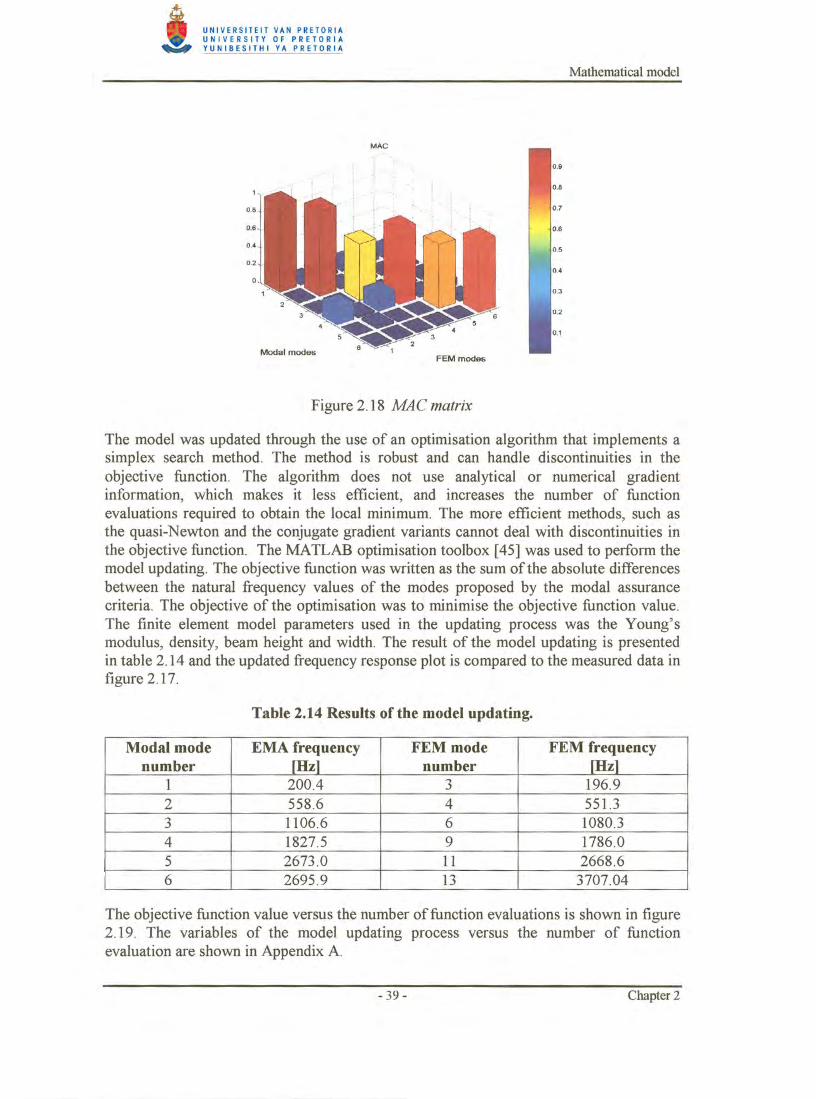
The modal assurance criteria compare all the measured mode shapes to all the finite element mode shapes and renders a value between one and zero to indicate how well the modes compare. The values are presented in a matrix format. A value above 0.7 indicates that the two modes have approximately the same shape.
- 37- Chapter 2
Machine tool dynamics
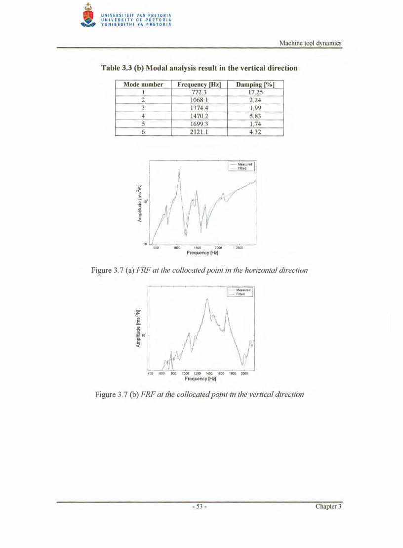
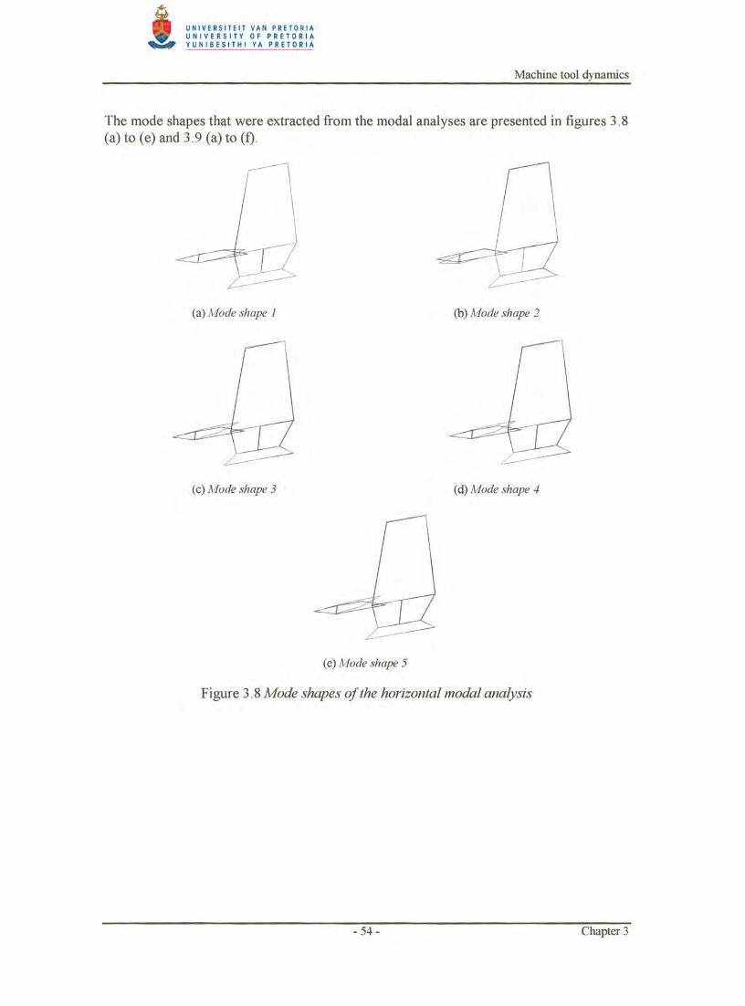
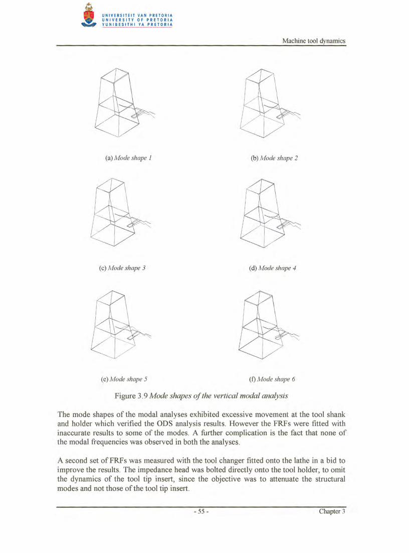
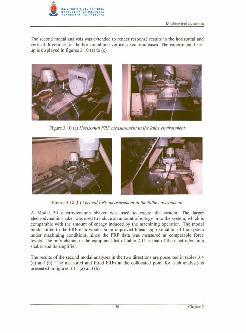
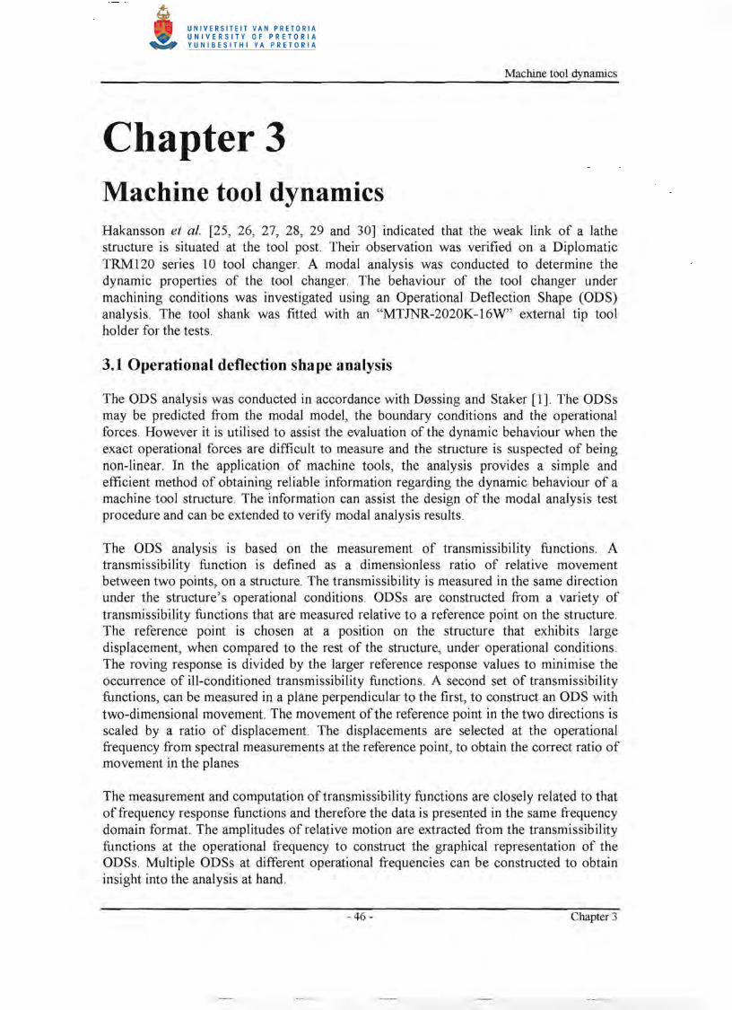
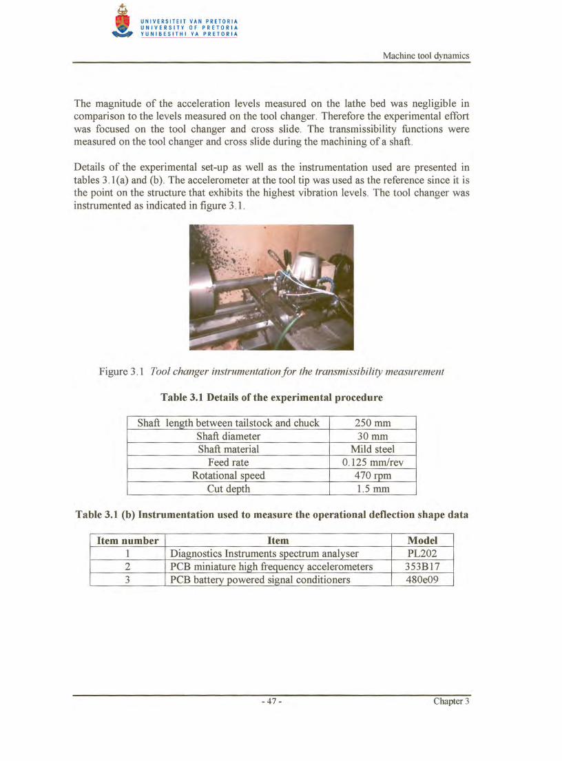
Chapter 3 Machine tool dynamics Hakansson et al. [25, 26, 27, 28, 29 and 30] indicated that the weak link of a lathe structure is situated at the tool post. Their observation was verified on a Diplomatic TRM120 series 10 tool changer. A modal analysis was conducted to determine the dynamic properties of the tool changer. The behaviour of the tool changer under machining conditions was investigated using an Operational Deflection Shape (ODS) analysis. The tool shank was fitted with an "MTJNR-2020K-16W" external tip tool holder for the tests.
3.1 Operational deflection shape analysis
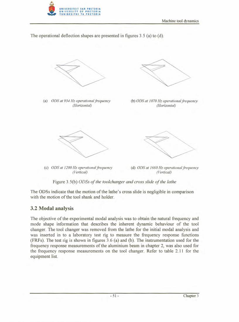
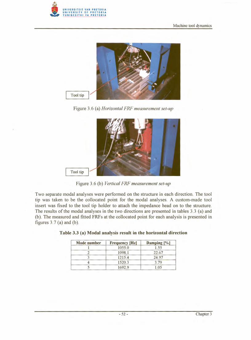
The ODS analysis was conducted in accordance with D0ssing and Staker [1]. The ODSs may be predicted from the modal model, the boundary conditions and the operational forces . However it is utilised to assist the evaluation of the dynamic behaviour when the exact operational forces are difficult to measure and the structure is suspected of being non-linear. In the application of machine tools, the analysis provides a simple and efficient method of obtaining reliable information regarding the dynamic behaviour of a machine tool structure. The information can assist the design of the modal analysis test procedure and can be extended to verify modal analysis results.
The ODS analysis is based on the measurement of transmissibility functions. A transmissibility function is defined as a dimensionless ratio of relative movement between two points, on a structure. The transmissibility is measured in the same direction under the structure' s operational conditions. ODSs are constructed from a variety of transmissibility functions that are measured relative to a reference point on the structure. The reference point is chosen at a position on the structure that exhibits large displacement, when compared to the rest of the structure, under operational conditions. The roving response is divided by the larger reference response values to minimise the occurrence of ill-conditioned transmissibility functions . A second set of transmissibility functions, can be measured in a plane perpendicular to the first, to construct an ODS with two-dimensional movement. The movement of the reference point in the two directions is scaled by a ratio of displacement. The displacements are selected at the operational frequency from spectral measurements at the reference point, to obtain the correct ratio of movement in the planes
The measurement and computation of transmissibility functions are closely related to that of frequency response functions and therefore the data is presented in the same frequency domain format. The amplitudes of relative motion are extracted from the transmissibility functions at the operational frequency to construct the graphical representation of the ODSs. Multiple ODSs at different operational frequencies can be constructed to obtain insight into the analysis at hand.
- 46- Chapter 3
Machine tool dynamics
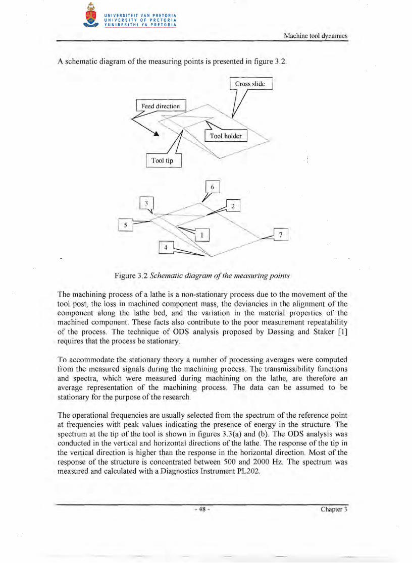
A schematic diagram of the measuring points is presented in figure 3.2.
Figure 3.2 Schematic diagram ofthe measuring points
The machining process of a lathe is a non-stationary process due to the movement of the tool post, the loss in machined component mass, the deviancies in the alignment of the component along the lathe bed, and the variation in the material properties of the machined component. These facts also contribute to the poor measurement repeatability of the process. The technique of ODS analysis proposed by D0ssing and Staker [1] requires that the process be stationary.
To accommodate the stationary theory a number of processing averages were computed from the measured signals during the machining process. The transmissibility functions and spectra, which were measured during machining on the lathe, are therefore an average representation of the machining process. The data can be assumed to be stationary for the purpose of the research.
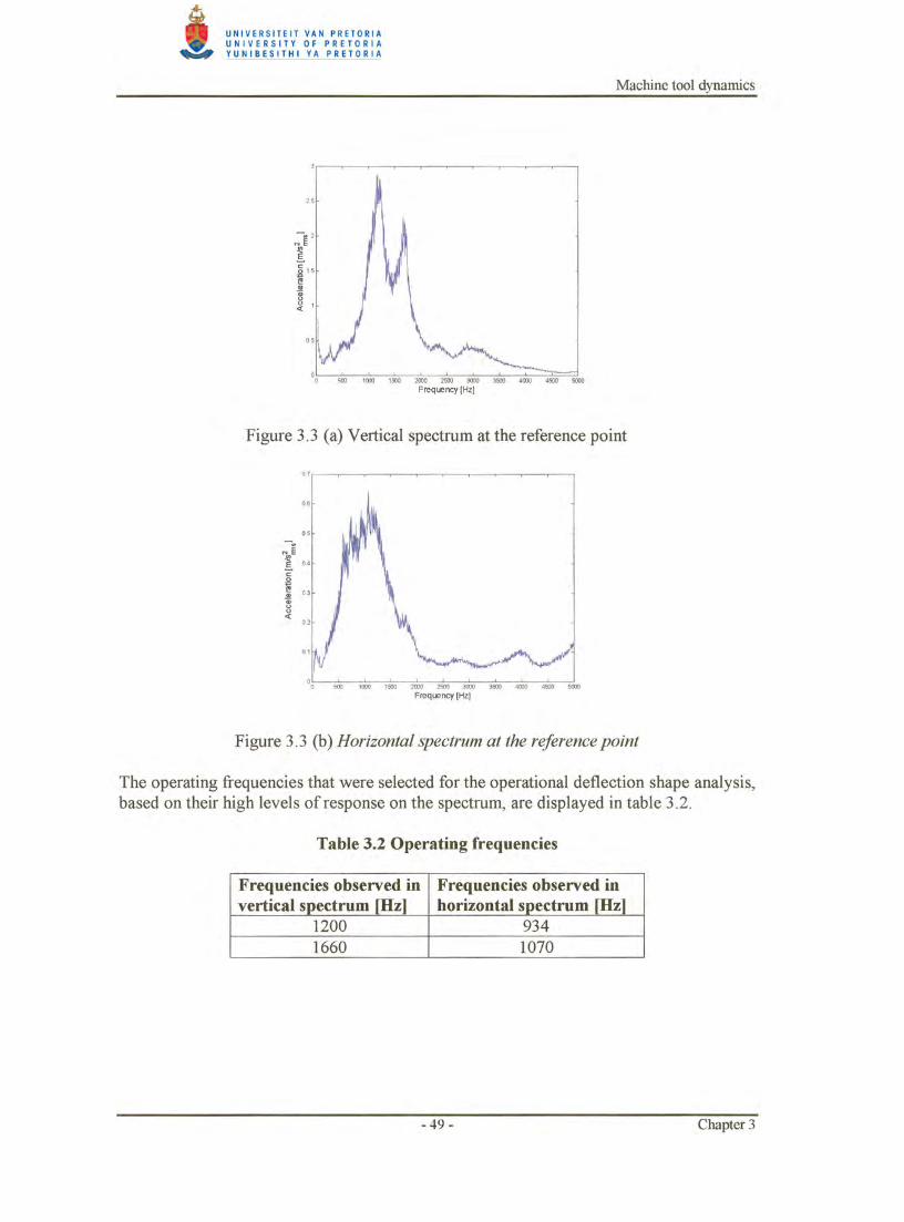
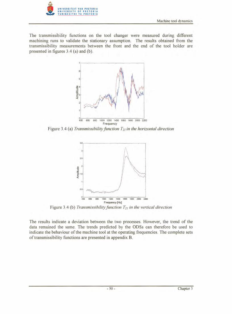
The operational frequencies are usually selected from the spectrum of the reference point at frequencies with peak values indicating the presence of energy in the structure. The spectrum at the tip of the tool is shown in figures 3.3(a) and (b). The ODS analysis was conducted in the vertical and horizontal directions of the lathe. The response of the tip in the vertical direction is higher than the response in the horizontal direction. Most of the response of the structure is concentrated between 500 and 2000 Hz. The spectrum was measured and calculated with a Diagnostics Instrument PL202.
- 48- Chapter 3