Embed Size (px)
Citation preview


G01-R03-0906
Introduction and Opening PreparationSTEP 1 – Things to Know Before You Begin ....................................................................................................3STEP 2 – Read Safety Information ..................................................................................................................4STEP 3 – Check Headroom, Backroom, Sideroom ..........................................................................................5STEP 4 – Removing the Existing Door Springs ...............................................................................................6STEP 5 – Removing Door Sections and Track .................................................................................................7STEP 6 – Preparing the Opening .....................................................................................................................7
Preparing the New DoorTypical Garage Door Installation Illustration .....................................................................................................8Hardware Components ....................................................................................................................................9
Installing the New DoorSTEP 7 – Preparing Bottom Section ..............................................................................................................10STEP 8 – Lift Handle Attachment............. ......................................................................................................12STEP 9 – Installing Door Sections.............. ...................................................................................................13STEP 10 – Reinforcing the Top Section for Opener Attachment ....................................................................14STEP 11 – Assembling and Installing Track ...................................................................................................15STEP 12 – Lock Installation (if included).................. ......................................................................................17STEP 13 – Pull Rope.......... ............................................................................................................................17STEP 14 – Spring Installation....... ................................................................................................................. .17STEP 15 – Attaching an Automatic Opener ....................................................................................................18
Maintenance/Adjustments/OptionsPainting and Windows ....................................................................................................................................19Maintenance ...................................................................................................................................................20Checking and Adjusting the Door ...................................................................................................................20Replacement Parts .........................................................................................................................................20
Table of Contents
STEP 1 – Things to Know Before You Begin• Read the instructions completely before starting the installation
of the door. Becoming familiar with the components before assembling the door will reduce the installation time.
• Be sure all hardware components for your new door are included before removing existing door (see pages 8,9). If your door is missing any parts, call the toll-free Consumer Services number listed on the front of this manual.
• Allow enough time to do the work; removing an existing door will take approximately 1-3 hours.
• An assistant may be required for lifting the unsprung door. It can weigh from 100 to 500 pounds.
• A typical installation takes between 9 and 12 hours to complete.• Keep in mind when planning the installation that the garage
will be open and unsecured when disassembling the old and assembling the new door.
• If the garage door is the only opening in the structure make sure everything you need is inside. You will have no way of leaving the garage until the track is assembled and installed. This will take approximately 5 hours.
• To avoid damage to the door, you must reinforce the top section of the door in order to provide a strengthened mounting point for attachment of an automatic opener (see page 14).
• Low Headroom doors require special instructions. Options for doors with low headroom can be found on page 5. Purchase of additional hardware may be required. Check headroom requirements in the chart on page 5 before beginning.
• To avoid installation problems which could result in personal injury or property damage, never reuse old track or hardware.
• Doors installed in high windload regions (Florida and other high wind prone areas) may require additional reinforcement beyond what is detailed in these instructions. Please refer to supplemental instructions for these areas.
• Express warranties apply only to doors installed using original, factory-supplied sections, parts, and hardware installed in strict accordance with these instructions.
Tools Needed• “C” Clamps or Locking Pliers• Hammer• Screwdriver• Tape Measure• Level• Socket wrench kit• Pliers• Drill, 1/4", 3/16", & 3/8" drill bits, and 7/16" socket bit• Step ladder• Saw horses (with carpet or other soft material on top surface;
2 needed for doors up to and includiing 9'0" wide, 3 needed for doors over 9'0" wide) or other supports for placing section on while assembling
• Hacksaw• Wood Saw• T-Square• Additional tools may be required; see the Spring Supplement for
more information.
Additional Material Required• Light household oil• 1-1/4" x 1-1/4" Minimum punched angle - 13 ga. (3/32") minimum thickness for Operator Reinforcement
(see page 14) - 16 ga. (1/16") minimum thickness for rear track hangers on
doors weighing up to 300 lbs. that use torsion springs, or doors weighing up to 150 lbs. that use extension springs. If your door exceeds these weight limitations, or if you do not know the weight of your door, 13 ga. angle should be used. (See page 16)
• Eight 3/8" x 1" bolts and nuts for rear track hangers• Six 5/16" x 11/2" lag screws for rear track hangers• Ten 10d 3" nails• Stop Molding• Wood Block• Rope
3

G01-R01-0704
• You can install your new garage door yourself IF…
a) you have help (it may weigh up to 500 lbs.);
b) you have the right tools and reasonable mechanical aptitude or experience; and
c) you follow these instructions very carefully.
• Garage doors use springs to balance them. There are two types of springs installed — extension or torsion. Each of these is available in either a standard or EZ-SetTM
assembly option. Please look at the drawings on page 8 to see which springs your old door has.
• If your old door uses torsion springs, do not attempt to remove the door or the springs yourself. Have a qualifi ed door repair service remove them. Attempting to remove a torsion spring assembly without proper training or tools may result in an uncontrolled release of spring forces which can cause serious or fatal injury.
• Only the track specifi ed and supplied with the door should be used.
• The brackets at the bottom corners of your garage door are under great tension. Do not attempt to loosen any bracket fasteners except when and as directed in detail in the following instructions. Otherwise, the bracket could spring out with dangerous force.
• Do not permit children to play beneath or with any garage door or electric operating controls.
• In removing a garage door that has extension springs, follow the instructions carefully, including the use of “C” clamps or locking pliers on both sides of the door in order to keep the door from moving once the springs are removed.
• Keep hands and fi ngers clear of section joints, track, and other door parts when the door is opening and closing to avoid injury. The lift handles are located for safe operation as well as easy use.
• Bolts must be installed at the rear end of horizontal tracks. These act to stop the rollers and keep the door from rolling off the back of the track.
• Track installations must use sway braces on the rear track hangers to prevent sideways movement. If the tracks are not fi rmly stabilized they might spread, allowing the door to fall and cause severe injury and damage.
• Springs, cables, and bottom fi xtures are under strong spring tension. Do not attempt to loosen any fasteners on these components. You could suddenly release spring forces and risk severe injury.
• If the garage door and/or any of the supporting track are damaged, operating the door could be hazardous. Call an authorized representative of the manufacturer or professional door repair service promptly.
• If repairs are ever required to your door, safety and trouble-free operation can be best assured by using original replacement parts.
• Once you have completed the installation of your new garage door, please be sure that your garage complies with all applicable ventilation requirements before you enclose any vehicles in the garage. Good ventilation avoids fi re and health hazards caused by fumes accumulating within a well-sealed garage.
• Clopay Building Products Company disclaims all liability for any installation that is not in compliance with applicable state or county building codes.
• Doors equipped with automatic door operators can cause serious injury or death if not properly adjusted and operated. To ensure safety of these doors:
a) test the sensitivity of the operator’s safety reverse mechanism monthly;
b) if your door has a pull down rope, you must remove the pull down rope;
c) make sure the door remains unlocked;
d) do not allow children to play with the controls.
STEP 2 – READ THIS SAFETY INFORMATIONIMPORTANT!
To Protect Yourself From Injury You Must Carefully Read The Following Safety Information and Warnings Before You Install Or Use Your New Garage Door
In the interest of safety this symbol means WARNING or CAUTION. Personal injury and/or property damage may occur unless instructions are followed carefully.
4
WARNING
G01-R02-0905
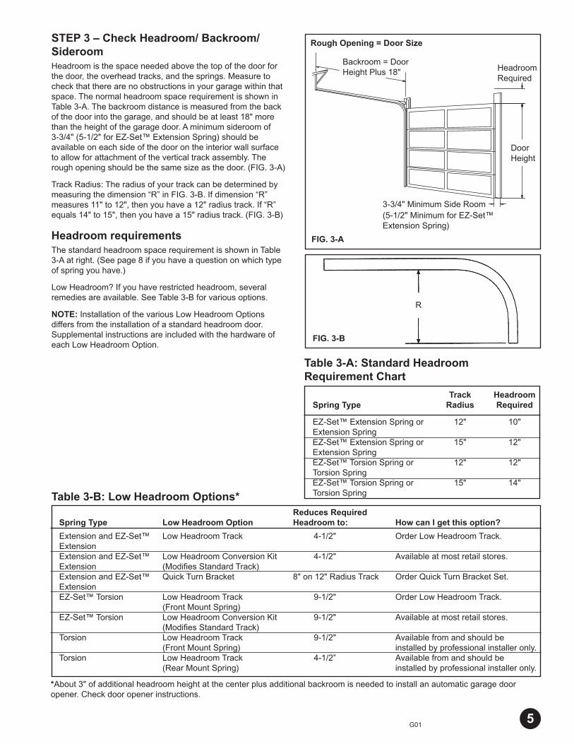
STEP 3 – Check Headroom/ Backroom/SideroomHeadroom is the space needed above the top of the door for the door, the overhead tracks, and the springs. Measure to check that there are no obstructions in your garage within that space. The normal headroom space requirement is shown in Table 3-A. The backroom distance is measured from the back of the door into the garage, and should be at least 18" more than the height of the garage door. A minimum sideroom of 3-3/4" (5-1/2" for EZ-Set™ Extension Spring) should be available on each side of the door on the interior wall surface to allow for attachment of the vertical track assembly. The rough opening should be the same size as the door. (FIG. 3-A)
Track Radius: The radius of your track can be determined by measuring the dimension “R” in FIG. 3-B. If dimension “R” measures 11" to 12", then you have a 12" radius track. If “R” equals 14" to 15", then you have a 15" radius track. (FIG. 3-B)
Headroom requirementsThe standard headroom space requirement is shown in Table 3-A at right. (See page 8 if you have a question on which type of spring you have.)
Low Headroom? If you have restricted headroom, several remedies are available. See Table 3-B for various options.
NOTE: Installation of the various Low Headroom Options differs from the installation of a standard headroom door. Supplemental instructions are included with the hardware of each Low Headroom Option.
Table 3-A: Standard Headroom Requirement Chart
Table 3-B: Low Headroom Options*
FIG. 3-B
FIG. 3-A
R
Rough Opening = Door Size
Backroom = Door Height Plus 18" Headroom
Required
Door Height
Reduces Required Spring Type Low Headroom Option Headroom to: How can I get this option?
Extension and EZ-Set™ Low Headroom Track 4-1/2" Order Low Headroom Track.ExtensionExtension and EZ-Set™ Low Headroom Conversion Kit 4-1/2" Available at most retail stores.Extension (Modifi es Standard Track) Extension and EZ-Set™ Quick Turn Bracket 8" on 12" Radius Track Order Quick Turn Bracket Set.Extension EZ-Set™ Torsion Low Headroom Track 9-1/2" Order Low Headroom Track. (Front Mount Spring)EZ-Set™ Torsion Low Headroom Conversion Kit 9-1/2" Available at most retail stores. (Modifi es Standard Track)Torsion Low Headroom Track 9-1/2" Available from and should be (Front Mount Spring) installed by professional installer only.Torsion Low Headroom Track 4-1/2” Available from and should be (Rear Mount Spring) installed by professional installer only.
5
Track Headroom Spring Type Radius Required
EZ-Set™ Extension Spring or 12" 10" Extension Spring EZ-Set™ Extension Spring or 15" 12" Extension Spring EZ-Set™ Torsion Spring or 12" 12" Torsion Spring EZ-Set™ Torsion Spring or 15" 14" Torsion Spring
3-3/4" Minimum Side Room(5-1/2" Minimum for EZ-Set™ Extension Spring)
*About 3" of additional headroom height at the center plus additional backroom is needed to install an automatic garage door opener. Check door opener instructions.
G01-R01-0704
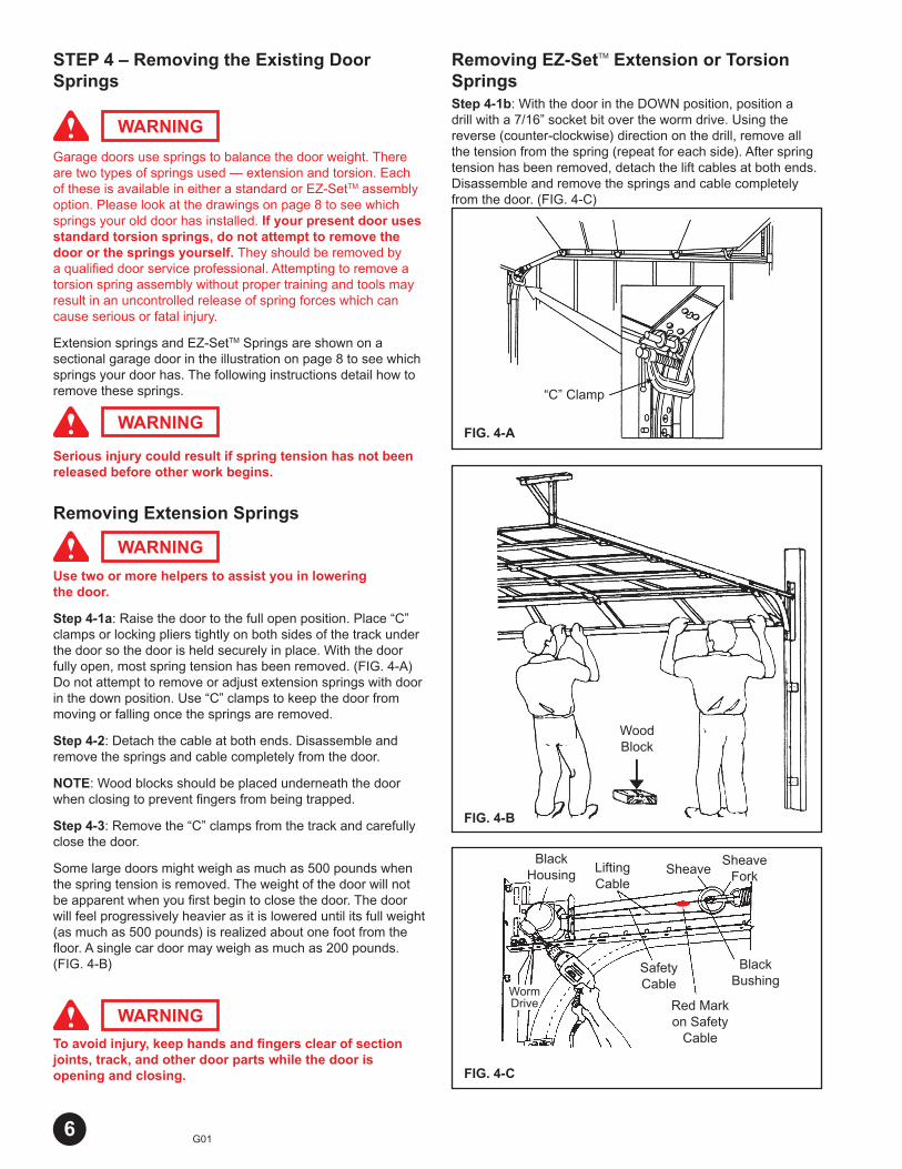
STEP 4 – Removing the Existing Door Springs
Garage doors use springs to balance the door weight. There are two types of springs used — extension and torsion. Each of these is available in either a standard or EZ-SetTM assembly option. Please look at the drawings on page 8 to see which springs your old door has installed. If your present door uses standard torsion springs, do not attempt to remove the door or the springs yourself. They should be removed by a qualifi ed door service professional. Attempting to remove a torsion spring assembly without proper training and tools may result in an uncontrolled release of spring forces which can cause serious or fatal injury.
Extension springs and EZ-SetTM Springs are shown on a sectional garage door in the illustration on page 8 to see which springs your door has. The following instructions detail how to remove these springs.
Serious injury could result if spring tension has not been released before other work begins.
Removing Extension Springs
Use two or more helpers to assist you in lowering the door.
Step 4-1a: Raise the door to the full open position. Place “C” clamps or locking pliers tightly on both sides of the track under the door so the door is held securely in place. With the door fully open, most spring tension has been removed. (FIG. 4-A) Do not attempt to remove or adjust extension springs with door in the down position. Use “C” clamps to keep the door from moving or falling once the springs are removed.
Step 4-2: Detach the cable at both ends. Disassemble and remove the springs and cable completely from the door.
NOTE: Wood blocks should be placed underneath the door when closing to prevent fi ngers from being trapped.
Step 4-3: Remove the “C” clamps from the track and carefully close the door.
Some large doors might weigh as much as 500 pounds when the spring tension is removed. The weight of the door will not be apparent when you fi rst begin to close the door. The door will feel progressively heavier as it is lowered until its full weight (as much as 500 pounds) is realized about one foot from the fl oor. A single car door may weigh as much as 200 pounds. (FIG. 4-B)
To avoid injury, keep hands and fi ngers clear of section joints, track, and other door parts while the door is opening and closing.
WARNING
WARNING
WARNING
WARNING
Removing EZ-SetTM Extension or Torsion SpringsStep 4-1b: With the door in the DOWN position, position a drill with a 7/16” socket bit over the worm drive. Using the reverse (counter-clockwise) direction on the drill, remove all the tension from the spring (repeat for each side). After spring tension has been removed, detach the lift cables at both ends. Disassemble and remove the springs and cable completely from the door. (FIG. 4-C)
FIG. 4-A
FIG. 4-B
FIG. 4-C
WoodBlock
“C” Clamp
BlackHousing Lifting
Cable
SheaveForkSheave
BlackBushing
Red Markon Safety
Cable
SafetyCable
WormDrive
6
P01-R01-07047
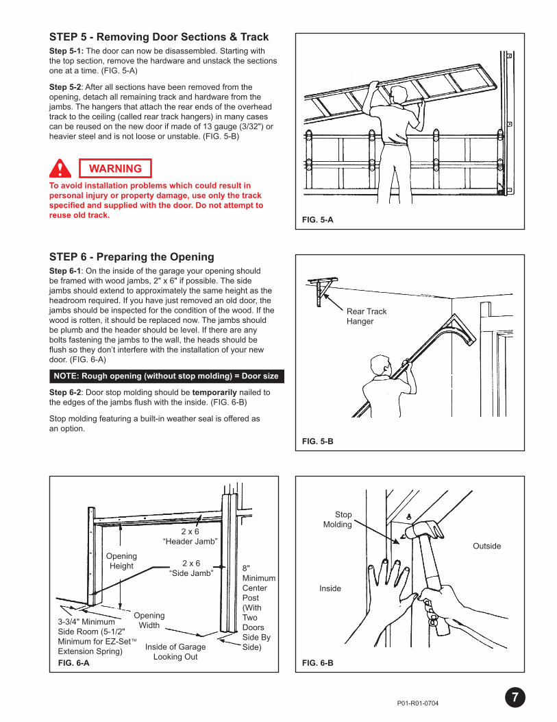
STEP 5 - Removing Door Sections & TrackStep 5-1: The door can now be disassembled. Starting with the top section, remove the hardware and unstack the sections one at a time. (FIG. 5-A)
Step 5-2: After all sections have been removed from the opening, detach all remaining track and hardware from the jambs. The hangers that attach the rear ends of the overhead track to the ceiling (called rear track hangers) in many cases can be reused on the new door if made of 13 gauge (3/32") or heavier steel and is not loose or unstable. (FIG. 5-B)
To avoid installation problems which could result in personal injury or property damage, use only the track specifi ed and supplied with the door. Do not attempt to reuse old track.
STEP 6 - Preparing the OpeningStep 6-1: On the inside of the garage your opening should be framed with wood jambs, 2" x 6" if possible. The side jambs should extend to approximately the same height as the headroom required. If you have just removed an old door, the jambs should be inspected for the condition of the wood. If the wood is rotten, it should be replaced now. The jambs should be plumb and the header should be level. If there are any bolts fastening the jambs to the wall, the heads should be fl ush so they don’t interfere with the installation of your new door. (FIG. 6-A)
NOTE: Rough opening (without stop molding) = Door size
Step 6-2: Door stop molding should be temporarily nailed to the edges of the jambs fl ush with the inside. (FIG. 6-B)
Stop molding featuring a built-in weather seal is offered as an option.
WARNING
FIG. 6-BFIG. 6-A
FIG. 5-B
FIG. 5-A
Rear Track Hanger
Outside
Inside
StopMolding
8" Minimum Center Post (With Two Doors Side By Side)
2 x 6 “Header Jamb”
OpeningHeight
Inside of Garage Looking Out
2 x 6 “Side Jamb”
OpeningWidth3-3/4" Minimum
Side Room (5-1/2" Minimum for EZ-SetTM Extension Spring)
P01-R01-0704
Right (Black) Cable Drum
Black Winding Cone
Center Bearing Plate
Stationary Cone
Standard Torsion Spring System
Left (Red) Cable Drum
End Bearing Plates
Red Winding Cone
Torsion Tube
EZ-Set™ Extension Spring System
EZ-Set™ Winding Unit
Sheave
Standard Extension Spring System
Stationary Sheave
Sheave
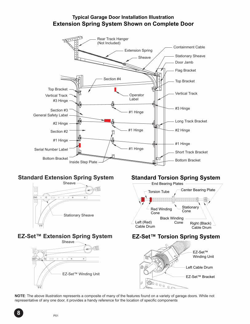
NOTE: The above illustration represents a composite of many of the features found on a variety of garage doors. While not representative of any one door, it provides a handy reference for the location of specifi c components
8
EZ-Set™ Torsion Spring System
EZ-Set™Winding Unit
Left Cable Drum
EZ-Set™ Bracket
Typical Garage Door Installation IllustrationExtension Spring System Shown on Complete Door
Rear Track Hanger(Not Included)
Extension Spring
Sheave Stationary Sheave
Door Jamb
Flag Bracket
Vertical Track
#3 Hinge
Long Track Bracket
#2 Hinge
OperatorLabel
#1 Hinge
#1 Hinge
#1 Hinge#1 Hinge
Short Track Bracket
Bottom BracketInside Step Plate
Section #4Top Bracket
Top Bracket
Vertical Track#3 Hinge
Section #3General Safety Label
#2 Hinge
Section #2
#1 Hinge
Serial Number Label
Bottom Bracket
Containment Cable
P01-R01-07049
Track Bracket(Longer)
Track Bracket(Shorter)
#2 Hinge
#4 Hinge(5 Section Doors Only)
#3 Hinge
Top Bracket
3/8"-18 x 3/4" Lg. Carriage Bolt
Bottom Bracket(1) LH + (1) RH
Flag Bracket(1) LH + (1) RH
Cable Assembly
Vertical Track
Curved Horizontal Track
3/8" Washer
Horizontal Angle
Struts*
1/4" x 3/4" Hex Head
Self-Tapping Screw
#14 x 5/8" Hex Head
Sheet Metal Screw
1/4" Flange Nut
3/8" Hex Nut
Lift Handle
Inside Step Plate
1/4" x 5/8" Track Bolt
5/16" x 1-5/8" Lag Bolt
#1 Hinge
Rollers
Description Description:Qty. Qty.Door Size:Door Size:
Single Car Doors8' - 9'W x 6'6'' - 7'0''H
Double Car Doors16'W x 6'6" - 7'0''H
4 Section Doors
5 Section Doors
Pull Rope
Single Car Doors8' - 9'W x 6'6'' - 7'0''H
Double Car Doors16'W x 6'6" - 7'0''H
Single Car Doors8' - 9'W x 6'6'' - 7'0''H
Double Car Doors16'W x 6'6" - 7'0''H
5 Section Doors
4 Section Doors
Single Car Doors8' - 9'W x 6'6'' - 7'0''H
Double Car Doors16'W x 6'6" - 7'0''H
Single Car Doors8' - 9'W x 6'6'' - 7'0''H
Double Car Doors16'W x 6'6" - 7'0"H
All Doors
All Doors
All Doors
Keyed Lock Kit (If included, parts are detailed in Lock instructions)
All Doors
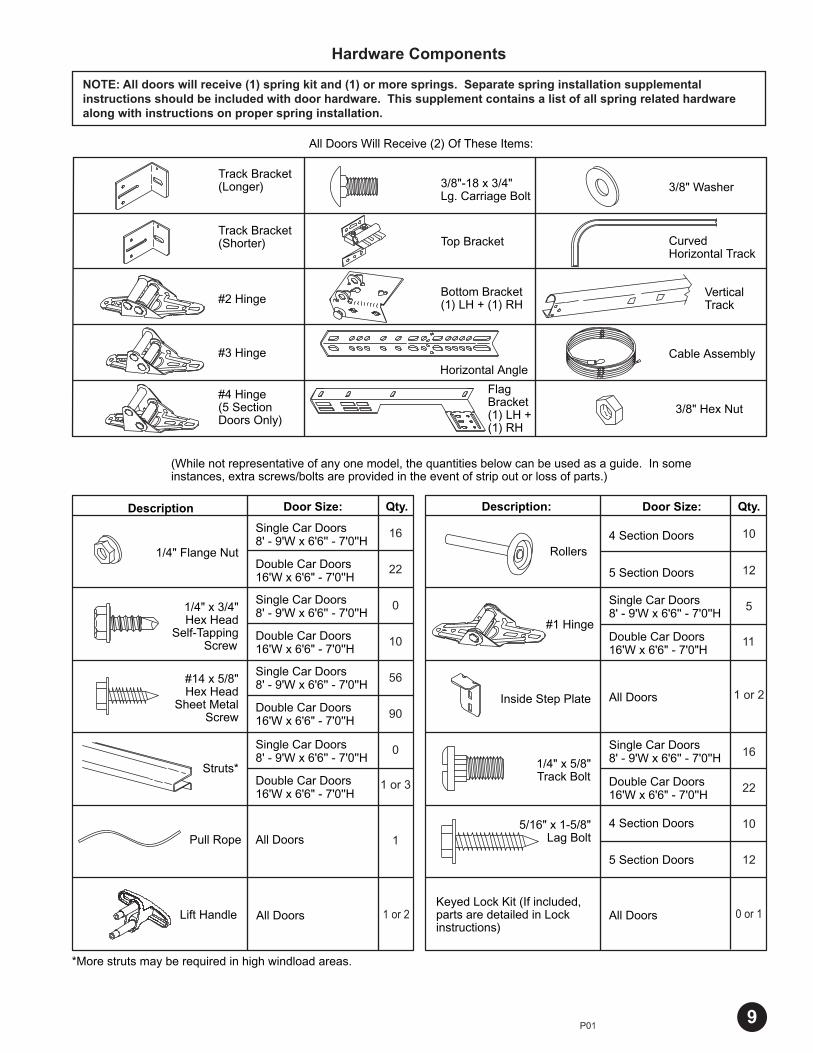
All Doors Will Receive (2) Of These Items:
(While not representative of any one model, the quantities below can be used as a guide. In some instances, extra screws/bolts are provided in the event of strip out or loss of parts.)
*More struts may be required in high windload areas.
Single Car Doors8' - 9'W x 6'6'' - 7'0''H
Double Car Doors16'W x 6'6" - 7'0''H
10
12
5
11
1 or 2
16
22
10
12
1 or 2 0 or 1
16
22
0
10
56
90
0
1 or 3
1
Hardware Components
NOTE: All doors will receive (1) spring kit and (1) or more springs. Separate spring installation supplemental instructions should be included with door hardware. This supplement contains a list of all spring related hardware along with instructions on proper spring installation.
P01-R01-0704
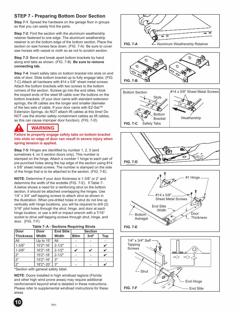
STEP 7 - Preparing Bottom Door SectionStep 7-1: Spread the hardware on the garage fl oor in groups so that you can easily fi nd the parts.
Step 7-2: Find the section with the aluminum weatherstrip retainer fastened to one edge. The aluminum weatherstrip retainer is on the bottom edge of the bottom section. Place the section on saw horses face down. (FIG. 7-A) Be sure to cover saw horses with carpet or cloth so as not to scratch section.
Step 7-3: Bend and break apart bottom brackets by hand along end tabs as shown. (FIG. 7-B) Be sure to remove connecting tab.
Step 7-4: Insert safety tabs on bottom bracket into slots on end stile of door. Slide bottom bracket up to fully engage tabs. (FIG. 7-C) Attach all hardware with #14 x 5/8” sheet metal screws. Attach the bottom brackets with two screws to the bottom corners of the section. Screws go into the end stiles. Hook the looped ends of the steel lift cable over the buttons on the bottom brackets. (If your door came with standard extension springs, the lift cables are the longer and smaller diameter of the two sets of cable. If your door came with EZ-Set™ Extension Springs, do NOT attach lift cables at this time! Do NOT use the shorter safety containment cables as lift cables, as this can cause improper door function). (FIG. 7-D)
Failure to properly engage safety tabs on bottom bracket into slots on edge of door can result in severe injury when spring tension is applied.
Step 7-5: Hinges are identifi ed by number 1, 2, 3 (and sometimes 4, on 5 section doors only). This number is stamped on the hinge. Attach a number 1 hinge to each pair of pre-punched holes along the top edge of the section using #14 x 5/8” sheet metal screws. The number is stamped on the side of the hinge that is to be attached to the section. (FIG. 7-E)
NOTE: Determine if your door thickness is 1-3/8” or 2” and determine the width of the endstile (FIG. 7-E). If Table 7-A below shows a need for a reinforcing strut on the bottom section, it should be attached overlapping the hinges. Use 1/4” x 3/4” self tapping screws to attach strut as shown in the illustration. When pre-drilled holes in strut do not line up vertically with hinge locations, you will be required to drill (2) 3/16” pilot holes through the strut, hinge, and door at each hinge location, or use a drill or impact wrench with a 7/16” socket to drive self-tapping screws through strut, hinge, and door. (FIG. 7-F)
NOTE: Doors installed in high windload regions (Florida and other high wind prone areas) may require additional reinforcement beyond what is detailed in these instructions. Please refer to supplemental windload instructions for these areas.
WARNING
End Stile Width
Door Thickness
Bottom Astragal
#1 Hinge
#14 x 5/8" Sheet Metal Screws
FIG. 7-C
FIG. 7-B
FIG. 7-A
Table 7- A - Sections Requiring Struts
Aluminum Weatherstrip Retainer
#14 x 5/8" Sheet Metal Screws
Weatherstrip
Safety Tabs
Bottom Bracket
Bottom Section
10
Slots
Door Door End Stile Section Thickness Width Width Bttm 3rd* Top All Up to 15' All - - - 1-3/8" 15'2"-16' 2-1/2" - - ✔
1-3/8" 16'2"-18' 2-1/2" ✔ ✔ ✔
2" 15'2"-18' 2-1/2" - - ✔
2" 15'2"-16' 3" - - - 2" 18'2"-20' 3" - - ✔
*Section with general safety label.
FIG. 7-D
End Hinge
1/4" x 3/4" Self Tapping Screws
End Stile
Strut
FIG. 7-F
FIG. 7-E
P01-R01-0704
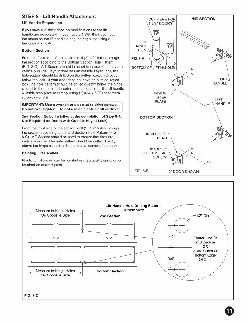
STEP 8 - Lift Handle AttachmentLift Handle Preparation
If you have a 2” thick door, no modifi cations to the lift handle are necessary. If you have a 1-3/8” thick door, cut the stems on the lift handle along the ridge line using a hacksaw (Fig. 8-A).
Bottom Section
From the front side of the section, drill (2) 1/2" holes through the section according to the Bottom Section Hole Pattern (FIG. 8-C). A T-Square should be used to ensure that they are vertically in line. If your door has an outside keyed lock, the hole pattern should be drilled on the bottom section directly below the lock. If your door does not have an outside keyed lock, the hole pattern should be drilled directly below the hinge closest to the horizontal center of the door. Install the lift handle & inside step plate assembly using (2) #14 x 5/8" sheet metal screws (Fig. 8-B).
IMPORTANT: Use a wrench or a socket to drive screws. Do not over tighten. Do not use an electric drill or driver.
2nd Section (to be installed at the completion of Step 9-4. Not Required on Doors with Outside Keyed Lock)
From the front side of the section, drill (2) 1/2" holes through the section according to the 2nd Section Hole Pattern (FIG. 8-C). A T-Square should be used to ensure that they are vertically in line. The hole pattern should be drilled directly above the hinge closest to the horizontal center of the door.
Painting Lift Handles
Plastic Lift Handles can be painted using a quality spray on or brushed on enamel paint.
Lift Handle Hole Drilling PatternOutside View
2nd Section
Bottom Section
Measure to Hinge HolesOn Opposite Side
Measure to Hinge HolesOn Opposite Side
3/4"
3/4" Center Line Of 2nd Section
OR2-3/4" Offset Of
Bottom Edge Of Door
1/2" Dia.
INSIDE STEP
PLATE
#14 X 5/8"SHEET METAL
SCREW
INSIDE STEP PLATE
BOTTOM SECTION
2" DOOR SHOWN
LIFTHANDLE
LIFTHANDLE
STEMS
CUT HERE FOR 1-3/8" DOORS
(BOTTOM OF LIFT HANDLE)
2ND SECTION
LIFTHANDLE
FIG. 8-C
FIG. 8-B
11
FIG 8-A

P01-R01-0704
STEP 9 - Installing Door SectionsStep 9-1: Place the section in the opening so that it is against the stop molding and centered from side to side. Place a level on the section and use a piece of wood under one end or the other (if necessary) to make the section level. (FIG. 9-A)
Step 9-2: Remove the level and drive a 3” nail in the jambs at each end and bend it over the edge of the section to hold the section in place. (FIG. 9-B)
NOTE: These nails are all that will hold the stacked door section in place until the tracks are secured to the back jambs. Be sure the nails hold the sections fi rmly in position.
Step 9-3: With the Table 9-A below, determine the order in which you will attach the remaining sections.
NOTE: If a lock assembly was ordered with the door, the holes for the lock may be predrilled. (Lock templates are included in the lock instructions for doors without predrilled holes.)
* Section with general safety label.
Step 9-4: Place the next section face down on the saw horses. If your door is predrilled for a lock, this section will be the one with holes in the center of the panel face. Identify the bottom edge as shown in the illustration. (FIG. 9-C)
Attach a number 2 hinge to each end at the top edge using #14 x 5/8" sheet metal screws. Remember that the number is stamped on the side of the hinge that is to be attached to the section. Attach a number 1 hinge to all other pre-punched holes along the top edge of the section.
Step 9-5: Keyed Lock Installation. If you wish to install a keyed lock, begin the lock installation now according to the supplemental instructions included with the lock hardware. If your door did not come with a keyed lock, install lift handle as shown on previous page.
1st 2nd Door (Bottom) (Lock) 3rd 4th 5thHeight Section Section Section* Section Section 6'0" 18" 18" 18" 18" -6'3" 18" 18" 18" 21" -6'6" 21" 18" 18" 21" -6'9" 21" 21" 18" 21" -7'0" 21" 21" 21" 21" -7'6" 18" 18" 18" 18" 18"7'9" 18" 18" 18" 18" 21"8'0" 21" 18" 18" 18" 21"
FIG. 9-A
#2 Hinge
#1 Hinge
Bottom EdgeEnd Stile
#14 x 5/8" Sheet Metal Screws
12
Table 9-A - Section Order for Various Door Heights
FIG. 9-B
FIG. 9-C
Stop Molding
P01-R01-0704
Top Bracket
#1 HingeBottom Bracket
#2, 3, or 4 Hinge
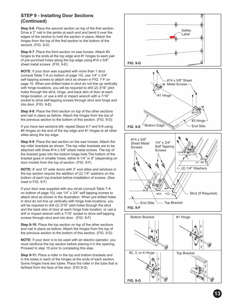
STEP 9 - Installing Door Sections (Continued)
Step 9-6: Place the second section on top of the fi rst section. Drive a 3" nail in the jambs at each end and bend it over the edges of the section to hold the section in place. Attach the hinges from the top of the fi rst section to the bottom of the second. (FIG. 9-D)
Step 9-7: Place the third section on saw horses. Attach #3 hinges to the ends at the top edge and #1 hinges to each pair of pre-punched holes along the top edge using #14 x 5/8" sheet metal screws. (FIG. 9-E)
NOTE: If your door was supplied with more than 1 strut (consult Table 7-A on bottom of page 10), use 1/4” x 3/4" self tapping screws to attach strut as shown in FIG. 7-F on page 10. When pre-drilled holes in strut do not line up vertically with hinge locations, you will be required to drill (2) 3/16” pilot holes through the strut, hinge, and back skin of door at each hinge location, or use a drill or impact wrench with a 7/16” socket to drive self-tapping screws through strut and hinge and into door. (FIG. 9-E)
Step 9-8: Place the third section on top of the other sections and nail in place as before. Attach the hinges from the top of the previous section to the bottom of this section. (FIG. 9-D)
If you have two sections left, repeat Steps 9-7 and 9-8 using #4 hinges on the end of the top edge and #1 hinges to all other stiles along the top edge.
Step 9-9: Place the last section on the saw horses. Attach the top roller brackets as shown. The top roller brackets are to be attached with three #14 x 5/8” sheet metal screws. The top of the bracket goes into the bottom hinge hole.The bottom of the bracket goes in smaller holes, either 6-1/4” or 8” (depending on door model) from the top of section. (FIG. 9-F)
NOTE: 8’ and 10’ wide doors with 3” end stiles and windows in the top section require the addition of (2) 1/4” washers on the bottom of each top bracket before installation of screws. (See inset in FIG. 9-F)
If your door was supplied with any struts (consult Table 7-A on bottom of page 10), use 1/4” x 3/4” self tapping screws to attach strut as shown in the illustration. When pre-drilled holes in strut do not line up vertically with hinge hole locations, you will be required to drill (2) 3/16” pilot holes through the strut and the back skin of door at each hinge hole location, or use a drill or impact wrench with a 7/16” socket to drive self-tapping screws through strut and into door. (FIG. 9-F)
Step 9-10: Place the top section on top of the other sections and nail in place as before. Attach the hinges from the top of the previous section to the bottom of this section. (FIG. 9-D)
NOTE: If your door is to be used with an electric operator, you must reinforce the top section before placing it in the opening. Proceed to step 10 prior to completing this step.
Step 9-11: Place a roller in the top and bottom brackets and in the tubes in each of the hinges at the ends of each section. Some hinges have two tubes. Place the roller in the tube that is farthest from the face of the door. (FIG 9-G)
Safety Label
FIG. 9-D
#3 Hinge
End StileBottom Edge
#1 Hinge
#14 x 5/8" Sheet Metal Screws
#14 x 5/8" Sheet Metal Screws
1/4" x 3/4" Self TappingScrews
End Stile Top Bracket
Strut (If Required)
(2) 1/4" Washers
FIG. 9-E
FIG. 9-F
13
FIG. 9-G

P01-R01-0704
STEP 10 - Reinforcing the Top Section for Opener To avoid damage to your door, you must reinforce the top section of the door in order to provide a mounting point for the opener to be attached. You will need one (1) or three (3) pieces of 1-1/4" x 1-1/4" minimum punched angle at least 13 gauge or 3/32" thick from your local hardware or building supply store. Figures 10-A to 10-D show how punched angle is to be affi xed to door. Angle iron may need to be trimmed depending on door section height and distance between center stiles.
Do NOT install the bracket supplied with the opener. Failure to reinforce the door, as illustrated, will void your warranty.
Required Materials:(1) 18" or 21" length of angle iron,(2) #14 x 5/8" sheet metal screws, and (2) 1/4" x 3/4" self tapping screws.
18'' or 21''
Punched Angle - Two 18'' or 21'' pieces (measure top section height).
Strut
Notch Cut on Vertical Angle
5'' 15'0'' up to 15'10'' & 19'0'' up to 20'0'' Wide Doors
with Strut
Punched Angle for Operator Draw Bar
Attachment
18'' or 21''
Strut
Notch Cut on Vertical Angle
5'' 16'0'' up to 18'0'' Wide Doors with Strut
Required materials: (2) 18” or 21” lengths of angle iron, (2) ¼’’x1’’ bolts, (2) ¼’’ lock washers, (2) ¼’’ nuts, (4) #14 x 5/8" sheet metal screws, and (4) 1/4" x 3/4" self tapping screws.
NOTE: An opener bracket kit specifi cally designed for opener attachment may be included or may be purchased as an option (silver galvanized or white powder coated). Instructions are provided with the kit.
NOTE: Operator may be attached up to 2 feet off center. (Doors with Torsion Springs Only)
FIG. 10-B
FIG. 10-D
Required materials: (2) 18” or 21” and (1) 27” or 50” length of angle iron(2) ¼’’x1’’ bolts, (2) ¼’’ lock washers, (2) ¼’’ nuts,(8) #14 x 5/8" sheet metal screws.
8'0'' up to 9'0'' Wide Doors
Vertical Punched Angle18" or 21" Long
Punched Angle - One 27'' long piece (12' wide doors require one 50'' long piece) and two 18'' or 21'' pieces (measure top section height).
18'' or 21''
Notch Cut on Vertical Angle
2''
Punched Angle for Operator Draw
Bar Attachment
18'' or 21''18'' or 21''18'' or 21''27'' or 50''
10'0'' up to 14'10'' Wide Doors
Required materials: (1) 18" or 21" length of angle iron, and (4) #14 x 5/8" sheet metal screws.
FIG. 10-A
FIG. 10-C
14
G01-R02-0905
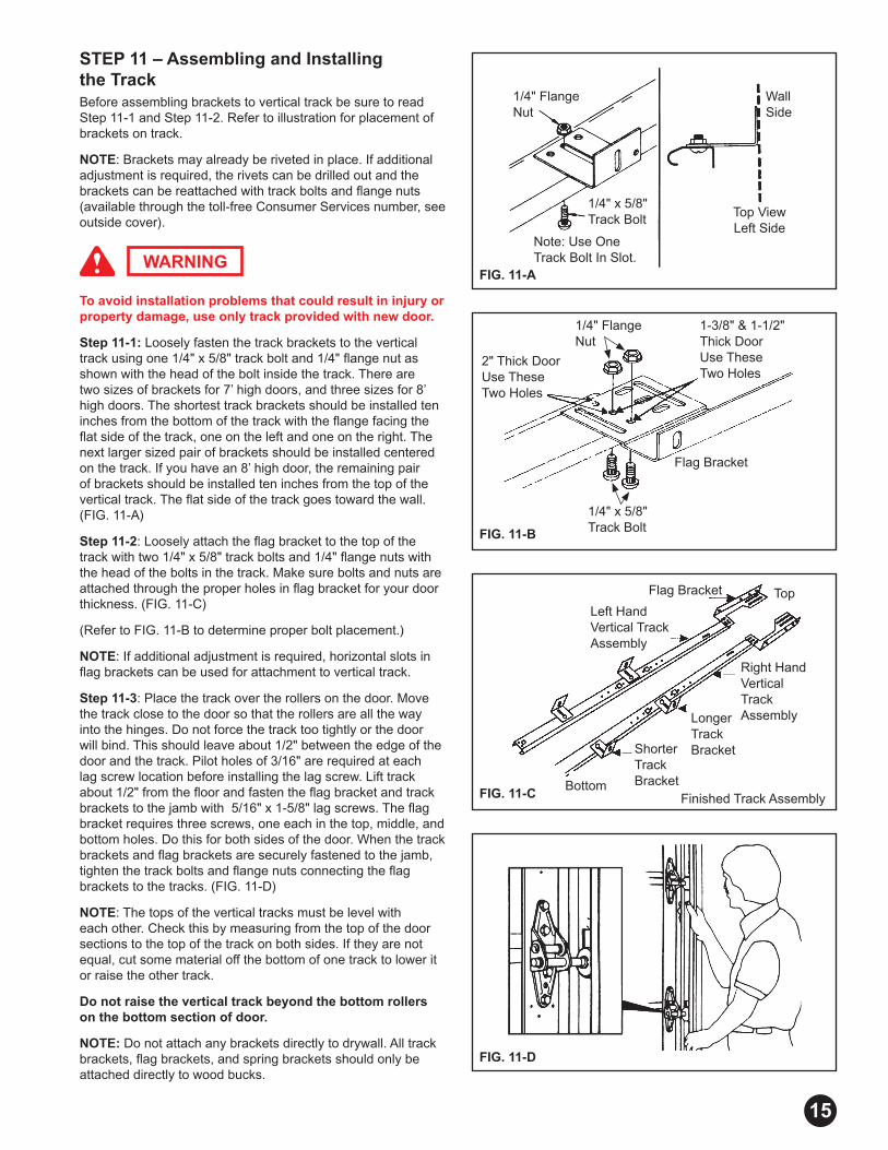
STEP 11 – Assembling and Installing the TrackBefore assembling brackets to vertical track be sure to read Step 11-1 and Step 11-2. Refer to illustration for placement of brackets on track.
NOTE: Brackets may already be riveted in place. If additional adjustment is required, the rivets can be drilled out and the brackets can be reattached with track bolts and fl ange nuts (available through the toll-free Consumer Services number, see outside cover).
To avoid installation problems that could result in injury or property damage, use only track provided with new door.
Step 11-1: Loosely fasten the track brackets to the vertical track using one 1/4" x 5/8" track bolt and 1/4" fl ange nut as shown with the head of the bolt inside the track. There are two sizes of brackets for 7’ high doors, and three sizes for 8’ high doors. The shortest track brackets should be installed ten inches from the bottom of the track with the fl ange facing the fl at side of the track, one on the left and one on the right. The next larger sized pair of brackets should be installed centered on the track. If you have an 8’ high door, the remaining pair of brackets should be installed ten inches from the top of the vertical track. The fl at side of the track goes toward the wall. (FIG. 11-A)
Step 11-2: Loosely attach the fl ag bracket to the top of the track with two 1/4" x 5/8" track bolts and 1/4" fl ange nuts with the head of the bolts in the track. Make sure bolts and nuts are attached through the proper holes in fl ag bracket for your door thickness. (FIG. 11-C)
(Refer to FIG. 11-B to determine proper bolt placement.)
NOTE: If additional adjustment is required, horizontal slots in fl ag brackets can be used for attachment to vertical track.
Step 11-3: Place the track over the rollers on the door. Move the track close to the door so that the rollers are all the way into the hinges. Do not force the track too tightly or the door will bind. This should leave about 1/2" between the edge of the door and the track. Pilot holes of 3/16" are required at each lag screw location before installing the lag screw. Lift track about 1/2" from the fl oor and fasten the fl ag bracket and track brackets to the jamb with 5/16" x 1-5/8" lag screws. The fl ag bracket requires three screws, one each in the top, middle, and bottom holes. Do this for both sides of the door. When the track brackets and fl ag brackets are securely fastened to the jamb, tighten the track bolts and fl ange nuts connecting the fl ag brackets to the tracks. (FIG. 11-D)
NOTE: The tops of the vertical tracks must be level with each other. Check this by measuring from the top of the door sections to the top of the track on both sides. If they are not equal, cut some material off the bottom of one track to lower it or raise the other track.
Do not raise the vertical track beyond the bottom rollers on the bottom section of door.
NOTE: Do not attach any brackets directly to drywall. All track brackets, fl ag brackets, and spring brackets should only be attached directly to wood bucks.
WARNINGFIG. 11-A
FIG. 11-B
FIG. 11-C
FIG. 11-D
1/4" FlangeNut
1/4" x 5/8"Track Bolt
Note: Use One Track Bolt In Slot.
Top ViewLeft Side
Wall Side
2" Thick DoorUse These Two Holes
1-3/8" & 1-1/2" Thick Door Use These Two Holes
Flag Bracket
Right HandVerticalTrack AssemblyLonger
TrackBracketShorter
TrackBracketBottom
Finished Track Assembly
TopFlag Bracket
Left Hand Vertical Track Assembly
15
1/4" x 5/8"Track Bolt
1/4" FlangeNut

G01-R01-0704
STEP 11 - Assembling and Installing the Track (Continued)
NOTE: Pressure-treated lumber purchased after January 2004 is treated with chemicals that have highly corrosive effects on metal fasteners. The fasteners provided with your door are intended for use with standard lumber (not pressure-treated) only. If you are installing your door into an opening framed with pressure-treated lumber purchased after January 2004, two items must be changed: 1) 5/16” x 1-5/8” lag screws with a minimum galvanization equivalent to G185 must be purchased for this application, and 2) to prevent potential corrosion between lumber and track/spring components, paint either the surface of the pressure-treated lumber or those surfaces of the track and spring components that come in contact with the pressure-treated lumber.
Step 11- 4: Fasten the horizontal angle to the horizontal (curved) track with two 1/4" x 5/8" track bolts and 1/4" fl ange nuts so that the heads of the track bolts are on the inside of the track. On some doors this angle may be 82" long and will require three additional fasteners per side. If the angle has been preassembled, skip Step 11-4 and proceed with Step 11-5. (FIG. 11-E)
Step 11-5: Temporarily support the rear end of the track with a rope from the trusses overhead in the garage or on a tall ladder. (FIG. 11-F)
Step 11-6: Place the track over the roller in the top bracket. Attach the curved end of the horizontal track to the fl ag bracket with two 1/4" x 5/8" track bolts and 1/4" fl ange nuts so that the heads of the screws are on the inside of the track. The horizontal and vertical track must join together to form a continuous channel for the rollers. Attach the end of the horizontal angle to the top of the fl ag bracket with a 3/8” x 3/4” carriage bolt and 3/8” hex nut. Use the top set of slots for 15” radius track, the middle set of slots for 12” radius track, and the bottom set of slots for Low Headroom track. (FIG. 11-G)
Step 11-7: Rear track hangers need to be made at this time. Use 1-1/4" x 1-1/4" punched angle, 13 gauge or 3/32" steel. These are not provided with the standard hardware. They are used to attach the rear of the horizontal track to the ceiling joist.
Enough angle iron or punched angle should be purchased to make two rear track hangers. These hangers must be strong enough to hold the full weight of the door. Attach a bolt at least 1" long through the end of each track to stop the door at the end of its travel. (FIG. 11-H)
Sway braces must be used to prevent tracks from spreading and allowing door to fall, which could cause serious injury. Bolts placed in the end of each track (FIG. 11-H) must be at least 1" long to prevent the top section from exiting the track.
NOTE: Rear track hangers should not be mounted any farther than 6" from the end of horizontal track.
Step 11- 8: Placement of rear track hangers is critical for the door to operate properly. The rear track hangers should hold the horizontal track level and square to the door. Squareness should be measured by comparing two diagonal distances: 1) the distance from the top left-hand corner of the door to the rear of the right-hand horizontal track and 2) the distance from the top right-hand corner of the door to the rear of the left-hand horizontal track. (FIG. 11-I, opposite page)
WARNING
FIG. 11-H
FIG. 11-G
FIG. 11-F
FIG. 11-E
Horizontal Angle
Horizontal Track
Horizontal Track
VerticalTrack
Horizontal Angle Bracket
Flag Bracket
Sway Brace
Bolt BlocksDoor Travel
3/8" x 1"Bolts & Nuts(4 places)
16
Rope
Horizontal Track
Horizontal Angle
3/8" x 3/4"Carriage
Bolt
G01-R02-0905
SlideTop Roller Bracket
Slide Bolts
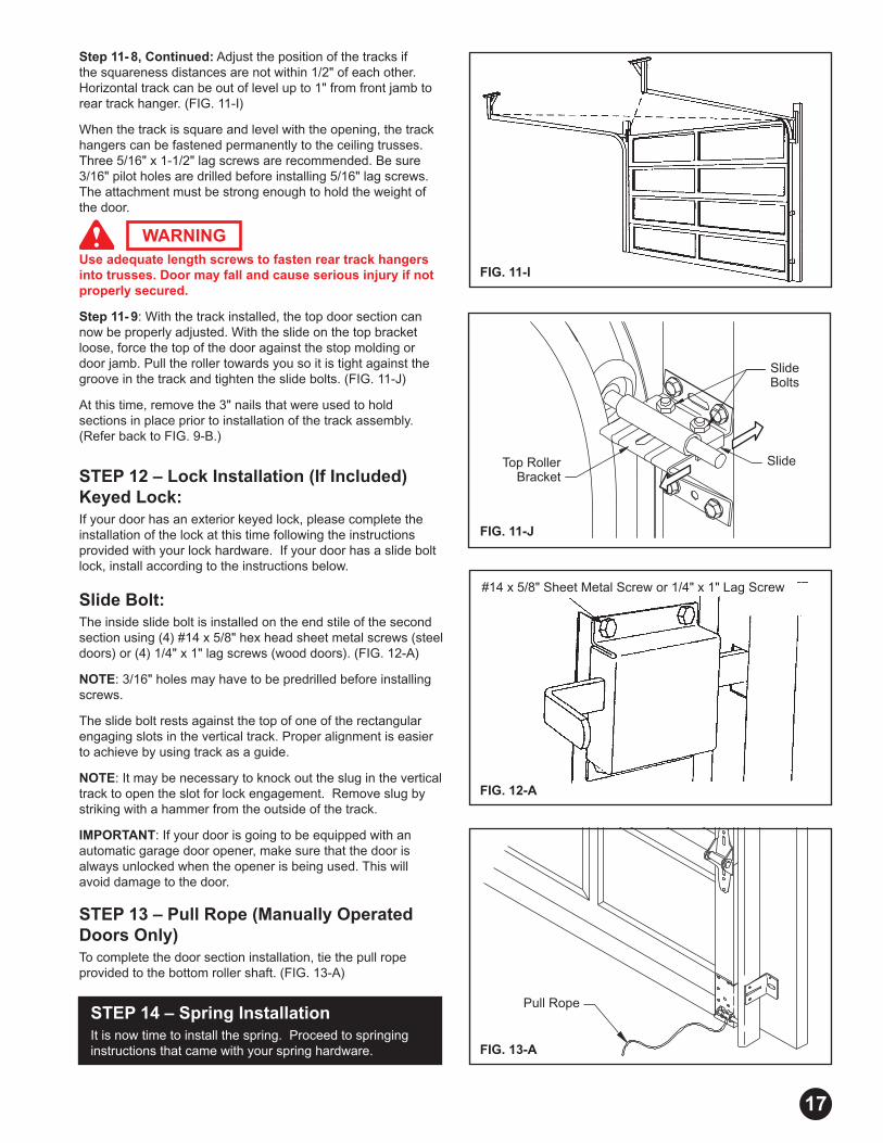
Step 11- 8, Continued: Adjust the position of the tracks if the squareness distances are not within 1/2" of each other. Horizontal track can be out of level up to 1" from front jamb to rear track hanger. (FIG. 11-I)
When the track is square and level with the opening, the track hangers can be fastened permanently to the ceiling trusses. Three 5/16" x 1-1/2" lag screws are recommended. Be sure 3/16" pilot holes are drilled before installing 5/16" lag screws. The attachment must be strong enough to hold the weight of the door.
Use adequate length screws to fasten rear track hangers into trusses. Door may fall and cause serious injury if not properly secured.
Step 11- 9: With the track installed, the top door section can now be properly adjusted. With the slide on the top bracket loose, force the top of the door against the stop molding or door jamb. Pull the roller towards you so it is tight against the groove in the track and tighten the slide bolts. (FIG. 11-J)
At this time, remove the 3" nails that were used to hold sections in place prior to installation of the track assembly. (Refer back to FIG. 9-B.)
STEP 12 – Lock Installation (If Included) Keyed Lock:If your door has an exterior keyed lock, please complete the installation of the lock at this time following the instructions provided with your lock hardware. If your door has a slide bolt lock, install according to the instructions below.
Slide Bolt:The inside slide bolt is installed on the end stile of the second section using (4) #14 x 5/8" hex head sheet metal screws (steel doors) or (4) 1/4" x 1" lag screws (wood doors). (FIG. 12-A)
NOTE: 3/16" holes may have to be predrilled before installing screws.
The slide bolt rests against the top of one of the rectangular engaging slots in the vertical track. Proper alignment is easier to achieve by using track as a guide.
NOTE: It may be necessary to knock out the slug in the vertical track to open the slot for lock engagement. Remove slug by striking with a hammer from the outside of the track.
IMPORTANT: If your door is going to be equipped with an automatic garage door opener, make sure that the door is always unlocked when the opener is being used. This will avoid damage to the door.
STEP 13 – Pull Rope (Manually Operated Doors Only)To complete the door section installation, tie the pull rope provided to the bottom roller shaft. (FIG. 13-A)
STEP 14 – Spring Installation It is now time to install the spring. Proceed to springing instructions that came with your spring hardware.
WARNING
Pull Rope
FIG. 13-A
FIG. 11-J
FIG. 11-I
FIG. 12-A
#14 x 5/8" Sheet Metal Screw or 1/4" x 1" Lag Screw
17
G01-R01-0704
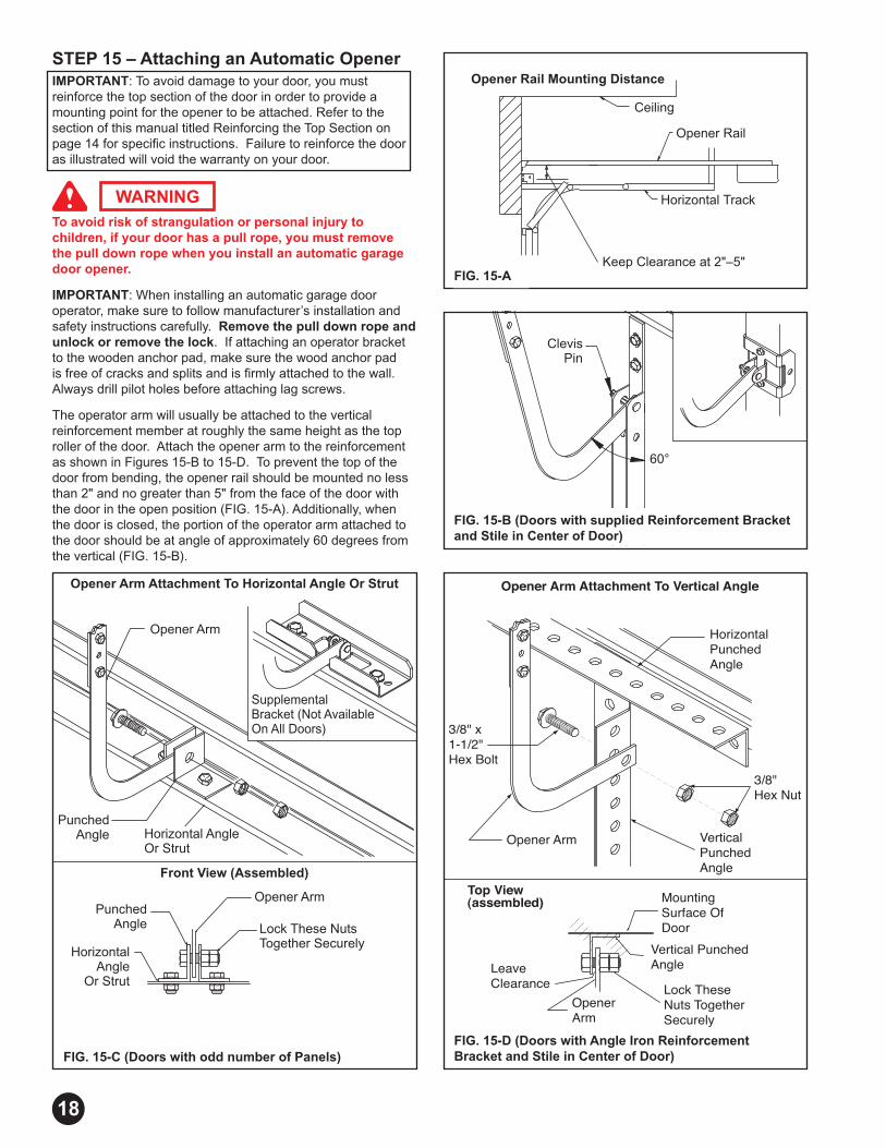
STEP 15 – Attaching an Automatic OpenerIMPORTANT: To avoid damage to your door, you must reinforce the top section of the door in order to provide a mounting point for the opener to be attached. Refer to the section of this manual titled Reinforcing the Top Section on page 14 for specifi c instructions. Failure to reinforce the door as illustrated will void the warranty on your door.
To avoid risk of strangulation or personal injury to children, if your door has a pull rope, you must remove the pull down rope when you install an automatic garage door opener.
IMPORTANT: When installing an automatic garage door operator, make sure to follow manufacturer’s installation and safety instructions carefully. Remove the pull down rope and unlock or remove the lock. If attaching an operator bracket to the wooden anchor pad, make sure the wood anchor pad is free of cracks and splits and is fi rmly attached to the wall. Always drill pilot holes before attaching lag screws.
The operator arm will usually be attached to the vertical reinforcement member at roughly the same height as the top roller of the door. Attach the opener arm to the reinforcement as shown in Figures 15-B to 15-D. To prevent the top of the door from bending, the opener rail should be mounted no less than 2" and no greater than 5" from the face of the door with the door in the open position (FIG. 15-A). Additionally, when the door is closed, the portion of the operator arm attached to the door should be at angle of approximately 60 degrees from the vertical (FIG. 15-B).
WARNING
Opener Rail Mounting Distance
Ceiling
Opener Rail
Horizontal Track
Keep Clearance at 2"–5"
Top View (assembled)
Opener Arm
Lock These Nuts Together Securely
LeaveClearance
Mounting Surface Of Door
Vertical Punched Angle
Opener Arm
3/8" x 1-1/2" Hex Bolt
3/8" Hex Nut
VerticalPunched Angle
HorizontalPunchedAngle
Opener Arm Attachment To Vertical Angle
FIG. 15-A
FIG. 15-D (Doors with Angle Iron Reinforcement Bracket and Stile in Center of Door)
18
FIG. 15-B (Doors with supplied Reinforcement Bracketand Stile in Center of Door)
60°
ClevisPin
FIG. 15-C (Doors with odd number of Panels)
Punched Angle
Opener Arm Attachment To Horizontal Angle Or Strut
Horizontal AngleOr Strut
Opener Arm
Supplemental Bracket (Not Available On All Doors)
Lock These Nuts Together Securely
Punched Angle
Horizontal Angle
Or Strut
Front View (Assembled)
Opener Arm