Embed Size (px)
Citation preview

Intelligent Com
pletions
03
3-1
Intelligent Completions
Introduction
Halliburton is the world's leading provider of intelligent completion technology to the upstream oil industry. Introduced in 1997, SmartWell® system technology was the industry's first intelligent well completion system and was designed specifically to remotely control and monitor specific reservoir zones.
Today, Halliburton offers a broad range of intelligent completion technologies from reservoir engineering studies to advanced completion design, zonal isolation and flow control, reservoir monitoring, and surface digital infrastructure solutions.
SmartWell systems provide an advanced reservoir management approach to optimizing well production through remote monitoring of wellbore parameters in real time. This technology also enables remote control of the reservoir without the need for mechanical intervention. In conjunction with reservoir models and prudent reservoir management processes, a SmartWell completion helps operators accelerate production and increase ultimate recovery to maximize return on investment (ROI).
Completion Solutions
3-2
SmartWell® Systems
A SmartWell® completion system optimizes productionby collecting, transmitting, and analyzing completion, production, and reservoir data; allowing remote selective zonal control and ultimately maximizing reservoir efficiency by:
» Helping increase production: Commingling of production from different reservoir zones increases and accelerates production and shortens field life.
» Helping increase ultimate recovery: Selective zonal control enables effective management of water injection, gas and water breakthrough, and individual zone productivity.
» Helping reduce capital expenditure: The ability to produce from multiple reservoirs through a single wellbore reduces the number of wells required for field development, thereby lowering drilling and completion costs. Size and complexity of surface handling facilities are reduced by managing water through remotezonal control.
» Helping reduce operating expenditure: Remote configuration of wells optimizes production without costly well intervention. Additionally, commingling of production from different reservoir zones shortens field life, thereby reducing operating expenditures.
SmartWell systems are designed to meet the demands of intelligent completions, worldwide, and in the most challenging environments.
A SmartWell system completion consists of some combination of zonal isolation devices, interval control devices, downhole control systems, permanent monitoring systems, surface control and monitoring systems, distributed temperature sensing systems, data acquisition and management software, and system accessories.
Reliability
Reliability is essential for intelligent completion systems, and Halliburton engineers reliability into all of its equipment. The company is ISO 9001 application certified and has developed processes to guide, monitor, and optimize system delivery and performance.
Halliburton maintains a detailed database to track the field performance of each SmartWell system installation. The knowledge gleaned from this data is used to calibrate design predictions and optimize the design and production process.
Completion Solutions | Intelligent Completions
3-3
Flow Control Valves
Halliburton offers interval control valves (ICVs) with and without shrouds and deflectors:
» HS-ICV: ICV for high-pressure/high-temperature (HP/HT) applications
» MCC-ICV: Cost-effective valve with choking capability
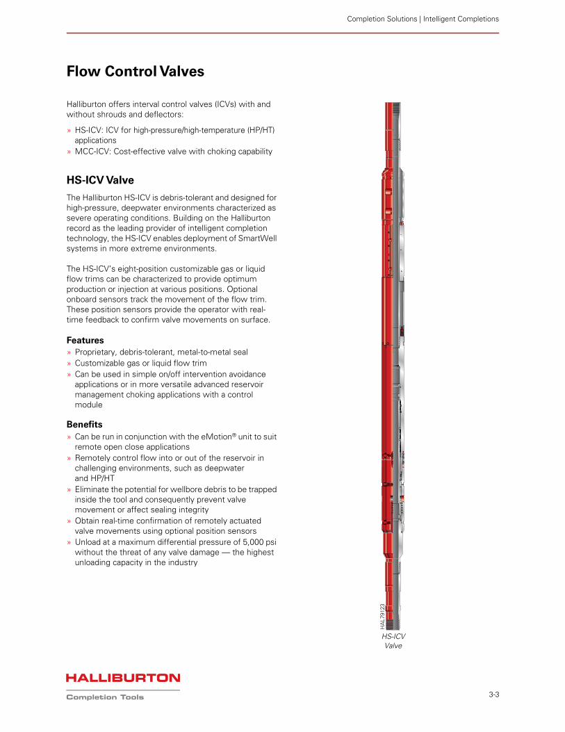
HS-ICV Valve
The Halliburton HS-ICV is debris-tolerant and designed for high-pressure, deepwater environments characterized as severe operating conditions. Building on the Halliburton record as the leading provider of intelligent completion technology, the HS-ICV enables deployment of SmartWell systems in more extreme environments.
The HS-ICV’s eight-position customizable gas or liquid flow trims can be characterized to provide optimum production or injection at various positions. Optional onboard sensors track the movement of the flow trim. These position sensors provide the operator with real-time feedback to confirm valve movements on surface.
Features» Proprietary, debris-tolerant, metal-to-metal seal» Customizable gas or liquid flow trim» Can be used in simple on/off intervention avoidance
applications or in more versatile advanced reservoir management choking applications with a controlmodule
Benefits
» Can be run in conjunction with the eMotion® unit to suit remote open close applications
» Remotely control flow into or out of the reservoir in challenging environments, such as deepwater and HP/HT
» Eliminate the potential for wellbore debris to be trapped inside the tool and consequently prevent valve movement or affect sealing integrity
» Obtain real-time confirmation of remotely actuated valve movements using optional position sensors
» Unload at a maximum differential pressure of 5,000 psi without the threat of any valve damage — the highest unloading capacity in the industry
HS-ICVValve
HA
L791
23
Completion Solutions
3-4
OperationHydraulically actuated, the HS-ICV is operated remotely from surface using the Halliburton Direct Hydraulics, Digital Hydraulics™, or the SmartPlex® downhole control system. The premium thermoplastic hydraulic chamber seals are designed to operate under high actuation pressures and temperatures. The valve has also been subjected to a stringent qualification program, including temperature, pressure, debris, and erosion tests.
The HS-ICV body has slots to accommodate two 1/4-in. dedicated instrument wires for position sensors and allows bypass of up to six 1/4-in. bare hydraulic control lines or instrument wires — all without compromising the valve body rating or working envelope.
Debris-Tolerant DesignThe HS-ICV is designed and tested such that the flow trim helps ensure complete metal-to-metal (MTM) seal integrity, even when exposed to heavy wellbore debris. A one-moving-piece valve mandrel design eliminates the potential for wellbore debris to be trapped inside the tool and consequently prevent valve movement.
Proprietary MTM SealThe HS-ICV houses a proprietary MTM interference fit seal that enables the valve to unload at a maximum differential pressure of 5,000 psi without the threat of any valve damage. Any additional tubing or annulus pressure acts on the MTM seal to help further ensure seal integrity, which has been rigorously tested and qualified at low- and high-pressure differentials.
Pressure-Balanced Valve MandrelA pressure-balanced valve mandrel design eliminates the need for a latch mechanism to hold trim closed or the need to maintain hydraulic pressure on the close chamber to keep the flow trim shut. This balanced sleeve design also prevents drifting of the sleeve in the incrementally open position.
Mandrel design also includes a shifting profile that allows for mechanical shifting of the sleeve in the event hydraulic control is compromised or if sleeve momentum is not achievable due to scale buildup inside the ICV.
Available in Three Variants» HSP premium choking ICV designed for more advanced
reservoir management when used in conjunction with a downhole control system
» HSB base choking ICV designed for more versatile choking applications when used in conjunction with a control module for incremental positioning
» HSO ICV designed for simple on/off applications
The flow trims on the HSB and HSP ICV can be customized to suit a particular well injection or production philosophy. Tungsten carbide is the material of choice for these flow trims to combat the threat of erosion caused by high flow rates.
Shrouded VersionsA shrouded HS-ICV configuration is available primarily for a two-zone stacked gravel pack application. The shrouds can also be shrink-fitted with a carbide insert when the valve is used in a stacked gravel pack injection application. Shrouds can also be fitted with screens for gas lift applications, depending on the OD/ID and pressure limitations.
Deflector Version This HS-ICV configuration is available primarily for high-rate gas or water injection applications. The deflectors are lined with tungsten carbide inserts to prevent erosional effects caused by impingement from high flow velocity exiting the valve flow trim.
Completion Solutions | Intelligent Completions
3-5
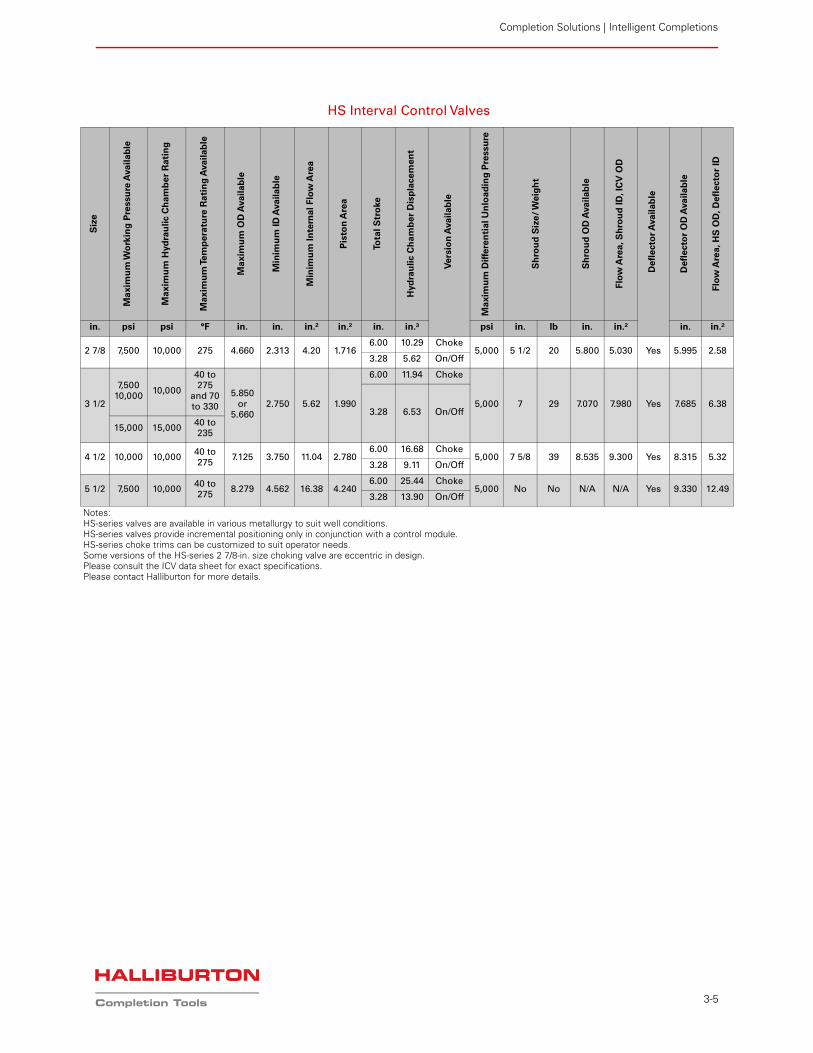
HS Interval Control Valves
Siz
e
Ma
xim
um
Wo
rkin
g P
ressu
re A
va
ilab
le
Ma
xim
um
Hyd
rau
lic C
ham
be
r R
ati
ng
Ma
xim
um
Tem
pe
ratu
re R
ati
ng
Ava
ilab
le
Ma
xim
um
OD
Ava
ilab
le
Min
imu
m I
D A
va
ila
ble
Min
imu
m I
nte
rna
l F
low
Are
a
Pis
ton
Are
a
Tota
l S
tro
ke
Hyd
rau
lic C
ha
mb
er
Dis
pla
ce
me
nt
Ve
rsio
n A
va
ilab
le
Ma
xim
um
Dif
fere
nti
al U
nlo
ad
ing
Pre
ssu
re
Sh
rou
d S
ize
/ W
eig
ht
Sh
rou
d O
D A
va
ila
ble
Flo
w A
rea
, S
hro
ud
ID
, IC
V O
D
De
fle
cto
r A
va
ilab
le
De
fle
cto
r O
D A
va
ila
ble
Flo
w A
rea, H
S O
D, D
efl
ecto
r ID
in. psi psi °F in. in. in.² in.² in. in.³ psi in. lb in. in.² in. in.²
2 7/8 7,500 10,000 275 4.660 2.313 4.20 1.7166.00 10.29 Choke
5,000 5 1/2 20 5.800 5.030 Yes 5.995 2.583.28 5.62 On/Off
3 1/2
7,50010,000
10,000
40 to 275
and 70 to 330
5.850 or
5.6602.750 5.62 1.990
6.00 11.94 Choke
5,000 7 29 7.070 7.980 Yes 7.685 6.383.28 6.53 On/Off
15,000 15,00040 to 235
4 1/2 10,000 10,00040 to 275
7.125 3.750 11.04 2.7806.00 16.68 Choke
5,000 7 5/8 39 8.535 9.300 Yes 8.315 5.323.28 9.11 On/Off
5 1/2 7,500 10,00040 to 275
8.279 4.562 16.38 4.2406.00 25.44 Choke
5,000 No No N/A N/A Yes 9.330 12.493.28 13.90 On/Off
Notes:HS-series valves are available in various metallurgy to suit well conditions.HS-series valves provide incremental positioning only in conjunction with a control module.HS-series choke trims can be customized to suit operator needs.Some versions of the HS-series 2 7/8-in. size choking valve are eccentric in design.Please consult the ICV data sheet for exact specifications.Please contact Halliburton for more details.
Completion Solutions
3-6
MC-Series Interval Control Valves
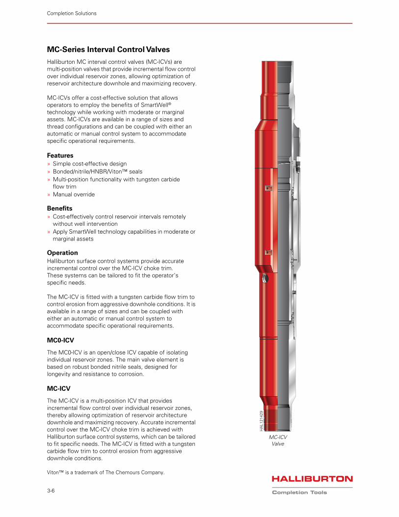
Halliburton MC interval control valves (MC-ICVs) are multi-position valves that provide incremental flow control over individual reservoir zones, allowing optimization of reservoir architecture downhole and maximizing recovery.
MC-ICVs offer a cost-effective solution that allows operators to employ the benefits of SmartWell® technology while working with moderate or marginal assets. MC-ICVs are available in a range of sizes and thread configurations and can be coupled with either an automatic or manual control system to accommodate specific operational requirements.
Features» Simple cost-effective design» Bonded/nitrile/HNBR/Viton™ seals» Multi-position functionality with tungsten carbide
flow trim» Manual override
Benefits» Cost-effectively control reservoir intervals remotely
without well intervention» Apply SmartWell technology capabilities in moderate or
marginal assets
OperationHalliburton surface control systems provide accurate incremental control over the MC-ICV choke trim. These systems can be tailored to fit the operator’s specific needs.
The MC-ICV is fitted with a tungsten carbide flow trim to control erosion from aggressive downhole conditions. It is available in a range of sizes and can be coupled with either an automatic or manual control system to accommodate specific operational requirements.
MC0-ICV
The MC0-ICV is an open/close ICV capable of isolating individual reservoir zones. The main valve element is based on robust bonded nitrile seals, designed for longevity and resistance to corrosion.
MC-ICV
The MC-ICV is a multi-position ICV that provides incremental flow control over individual reservoir zones, thereby allowing optimization of reservoir architecture downhole and maximizing recovery. Accurate incremental control over the MC-ICV choke trim is achieved with Halliburton surface control systems, which can be tailored to fit specific needs. The MC-ICV is fitted with a tungsten carbide flow trim to control erosion from aggressive downhole conditions.
Viton™ is a trademark of The Chemours Company.
MC-ICV Valve
HA
L121
429
Completion Solutions | Intelligent Completions
3-7
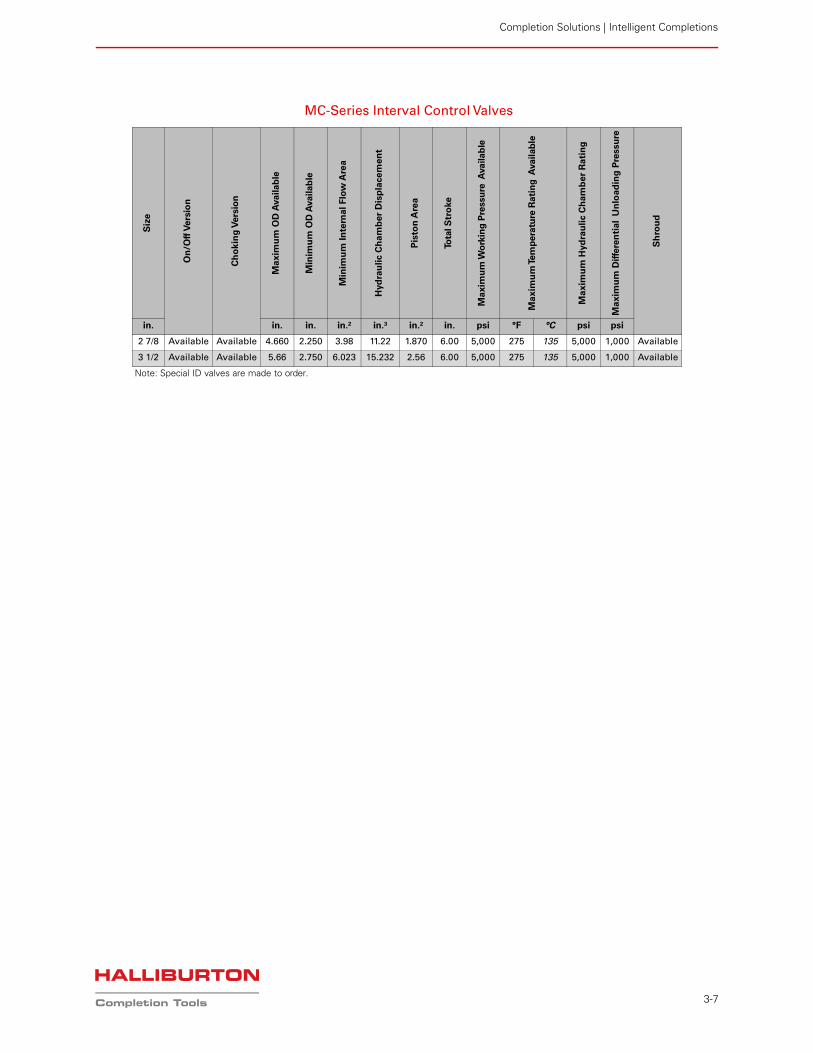
MC-Series Interval Control Valves
Siz
e
On
/Off
Vers
ion
Ch
ok
ing
Vers
ion
Ma
xim
um
OD
Availab
le
Min
imu
m O
D A
vailab
le
Min
imu
m I
nte
rna
l F
low
Are
a
Hyd
rau
lic C
ha
mb
er
Dis
pla
ce
me
nt
Pis
ton
Are
a
Tota
l S
tro
ke
Ma
xim
um
Wo
rkin
g P
ress
ure
Availab
le
Ma
xim
um
Tem
pera
ture
Rati
ng
Availab
le
Ma
xim
um
Hyd
rau
lic C
ha
mb
er
Rati
ng
Ma
xim
um
Dif
fere
nti
al
Un
loa
din
g P
ressu
re
Sh
rou
d
in. in. in. in.² in.³ in.² in. psi °F °C psi psi
2 7/8 Available Available 4.660 2.250 3.98 11.22 1.870 6.00 5,000 275 135 5,000 1,000 Available
3 1/2 Available Available 5.66 2.750 6.023 15.232 2.56 6.00 5,000 275 135 5,000 1,000 Available
Note: Special ID valves are made to order.
Completion Solutions
3-8
HS Circulating Valve
The HS circulating valve is designed for use in SmartWell® and conventional completion systems. Based on the proven HS interval control valve (ICV) design technology, the HS circulating valve is designed for safe and efficient circulation of completion fluids after landing the completion and setting the HF-1 and completion packer.
The HS circulating valve is a bi-directional hydraulically operated balanced piston valve with a gas-tight redundant sealing mechanism. The sealing mechanism consists of a debris-tolerant metal-to-metal (MTM) primary seal and a secondary thermoplastic seal array. The valve mandrel incorporates a carbide nose to prevent erosion of the sealing surface areas.
Features» Proprietary, debris-tolerant MTM seal» Redundant thermoplastic seal helps ensure gas-tight
seal integrity» Erosion-resistant carbide nose seal» High circulation rates» Remotely activated without intervention» Manual override shift profile» Bypass slots for 12 1/4-in. control lines
Benefits» Can be run in conjunction with an eMotion® unit to suit
remote open close applications» Run above the production packer, operated after packer
is set, providing improved well control» Helps eliminate need to circulate across packer
element, reducing risk of damage to the element» Prevents circulation pressures from impacting reservoir» Faster circulation rates, reducing rig time» Allows for circulating well kill fluid during workover
operations without the need for perforating tubing
OperationThe HS circulating valve is placed above the production packer in the completion string and is run into the well. During a SmartWell completion, once on depth, the HF-1
production packer is set via pressure down the production tubing. Element packoff integrity is then determined by applying pressure down the annulus. The open line of the valve is pressured up via the surface control unit to open the sleeve. Circulation down the annulus or tubing begins. Higher circulation rates can be attained because fluid is not circulated past the packer element. Once the desired volumes are circulated, the close line of the valve is pressured up to move the sleeve into the closed position. The tubing is then pressured up to a maximum 7,500 psi to test the sleeve integrity. A zero leak rate should be observed. Upon completion of a successful pressure test, the completion program can progress to the next step.
Field-Proven MTM SealThe HS circulating valve houses a proprietary MTM seal from the proven HS-ICV design. Any additional tubing or annulus pressure acts on the seal to help further ensure its integrity. The seal has been rigorously tested and qualified at low- and high-pressure (up to 10,000 psi) differentials.
Redundant Thermoplastic SealThe MTM seal is backed up by a redundant thermoplastic seal to achieve gas-tight sealing integrity. These field-proven thermoplastic metal energized (MSE) seals are designed for redundancy during low- and high-pressure applications. The MTM, along with the redundant thermoplastic seal, are qualified to provide gas-tight (zero leak) seal integrity.
Pressure-Balanced Valve MandrelA pressure-balanced valve mandrel design eliminates the need for a latch mechanism to hold the trim closed or the need to maintain hydraulic pressure on the close chamber to keep the flow trim shut. This balanced sleeve design prevents drifting of the sleeve in the open position. The valve mandrel design also includes a shifting profile that allows the sleeve to be mechanically shifted in the event hydraulic control is compromised, or if sleeve movement is not achievable because of scale buildup inside the ICV.
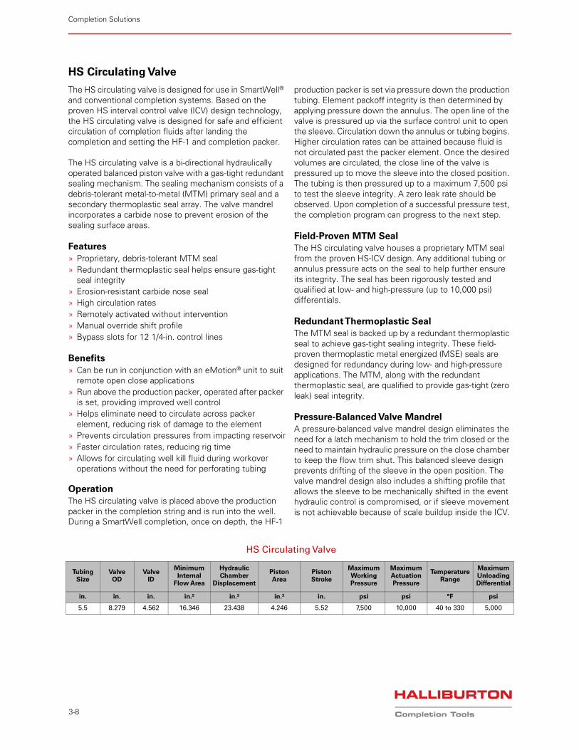
HS Circulating Valve
TubingSize
Valve OD
Valve ID
Minimum Internal
Flow Area
Hydraulic Chamber
Displacement
Piston Area
Piston Stroke
Maximum Working Pressure
Maximum Actuation Pressure
Temperature Range
Maximum Unloading Differential
in. in. in. in.² in.³ in.³ in. psi psi °F psi
5.5 8.279 4.562 16.346 23.438 4.246 5.52 7,500 10,000 40 to 330 5,000
Completion Solutions | Intelligent Completions
3-9
Zonal Isolation Packers
HF-1 Packer
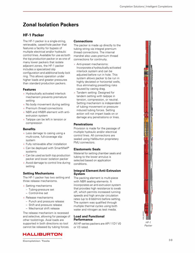
The HF-1 packer is a single-string, retrievable, cased-hole packer that features a facility for bypass of multiple electrical and/or hydraulic control lines. Available for use as both the top production packer or as one of many lower packers that isolate adjacent zones, the HF-1 packer includes a specialized slip configuration and additional body lock ring. This allows operation under higher loads and greater pressures than standard production packers.
Features» Hydraulically activated interlock
mechanism prevents premature setting
» No body movement during setting» Premium thread connections» NBR and HNBR element with anti-
extrusion system» Tailpipe can be left in tension or
compression
Benefits» Less damage to casing using a
multi-cone, full-coverage slip system
» Fully retrievable after installation» Can be deployed with SmartWell®
systems» Can be used as both top production
packer and lower isolation packer» Avoid damage to control line during
setting
Setting MechanismsThe HF-1 packer has two setting and three release mechanisms.
» Setting mechanisms– Tubing-pressure set– Control-line set
» Release mechanisms– Punch and pressure release– Shift and pressure release– Mechanical shift release
The release mechanism is recessed and selective, allowing for passage of other toolstrings. Axial loads are supported in both directions so tool cannot be released by tubing forces.
ConnectionsThe packer is made up directly to the tubing string via integral premium thread connections. The internal mandrel also uses premium thread connections for continuity.
» Anti-preset mechanisms: Incorporate a hydraulically activated interlock system and can be adjusted before run in hole. This system allows packer to be run in highly deviated or horizontal wells, thus eliminating presetting risks caused by casing drag.
» Tandem setting: Designed for tandem setting with tailpipe in tension, compression, or neutral. Setting mechanism is independent of tubing movement or pressure-induced tubing forces. Setting action will not impart loads on or damage any penetrations or lines.
PenetrationsProvision is made for the passage of multiple hydraulic and/or electrical control lines. All connections are sealed using Halliburton proprietary FMJ connectors.
Elastomeric SealsMaterial for setting chamber seals and tubing to the lower annulus is selected based on application conditions.
Integral Element Anti-Extrusion SystemThe packing element is multi-piece with NBR sealing elements. It incorporates an anti-extrusion system that provides high resistance to swab off, which permits increased running speeds and high annular circulation rates (up to 8 bbl/min) before setting. The system was qualified through multiple thermal cycles using both water and nitrogen as test media.
Load and Functional PerformanceAll HF-series packers are API 11D1 V0 or V3 rated.
HF-1Packer
HA
L802
91
Completion Solutions
3-10
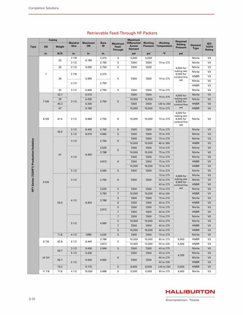
Retrievable Feed-Through HF Packers
Type
CasingMandrel
SizeMaximum
ODBore
IDMaximum
Feed-Through
Maximum Differential
Across Element
Working Pressure
Working Temperature
Required Setting
PressureElement
Type
ISO 14310 Rating
OD Weight
in. lb/ft in. in. in. psi psi °F psi
HF1
Seri
es
(722H
F1)
Pro
du
ctio
n/I
sola
tio
n
7
232 7/8
6.1802.315 4 5,000 5,000
75 to 275
4,500 for tubing set; 6,500 for
control line set
Nitrile V3
3 1/2 2.750 5 7,500 7,500 Nitrile V3
26 3 1/2 6.090 2.750 5 7,500 7,500 Nitrile V3
29
2 7/8
5.995
2.315
5 7,500 7,500 75 to 275
Nitrile V3
HNBR V3
3 1/2 2.750Nitrile V0
HNBR V3
32 3 1/2 5.905 2.750 5 7,500 7,500 75 to 275 Nitrile V3
7 5/8
33.7
3 1/2
6.570
2.750 5
7,500 7,50075 to 275 4,500 for
tubing set; 6,500 for
control line set
Nitrile V3
39 6.430 10,000 10,000 Nitrile V0
45.3 6.240 7,500 7,500 140 to 260 HNBR V0
47 6.180 10,000 10,000 75 to 275 HNBR V0
8 5/8 61.4 3 1/2 6.980 2.750 6 10,000 10,000 75 to 275
4,500 for tubing set; 6,500 for
control line set
Nitrile V0
9 5/8
43.53 1/2 8.440 2.750 6 7,500 7,500 75 to 275
4,500 for tubing set; 6,500 for
control line set
Nitrile V3
5 1/2 8.515 4.562 5 7,500 7,500 75 to 275 Nitrile V3
47
3 1/2
8.440
2.750 67,500 7,500 75 to 275 Nitrile V3
10,000 10,000 40 to 300 HNBR V3
4 1/2
3.5255
7,500 7,500 75 to 275 Nitrile V0
3.788 10,000 10,000 75 to 275 Nitrile V0
3.813 6
7,500 7,500 75 to 275 Nitrile V0
7,500 7,500 75 to 275 HNBR V3
10,000 10,000 75 to 275 HNBR V3
5 1/2 4.560 5 7,500 7,500 75 to 275 Nitrile V0
53.5
3 1/2
8.300
2.750 6 7,500 7,500
75 to 275 Nitrile V3
40 to 275 Nitrile V0
40 to 275 HNBR V0
4 1/2
3.525 5 7,500 7,500 75 to 275 Nitrile V0
3.783 7 10,000 10,000 40 to 200 HNBR V3
3.7885 7,500 7,500 75 to 275 Nitrile V3
6 7,500 7,500 40 to 275 HNBR V0
3.8135 7,500 7,500 75 to 275 Nitrile V3
7 7,500 7,500 40 to 275 HNBR V0
5 1/2 4.560
7 7,500 7,500 75 to 275 Nitrile V0
5 10,000 10,000 40 to 275 Nitrile V0
7 7,500 7,500 40 to 275 HNBR V0
5 10,000 10,000 40 to 275 HNBR V3
71.8 4 1/2 7.890 3.525 5 7,500 7,500 75 to 275 Nitrile V0
9 7/8 62.8 4 1/2 8.4403.788
510,000 10,000 80 to 275 5,000 HNBR V3
3.813 12,500 12,500 55 to 235 5,500 HNBR V3
10 3/4
60.73 1/2 9.430 2.949 5 7,500 7,500 45 to 275
4,100
Nitrile V0
5 1/2 9.430
4.5626
7,500 7,500 45 to 275 Nitrile V0
65.75 1/2
9.330 7,500 7,50080 to 275 Nitrile V0
40 to 230 HNBR V3
73.2 9.175 5 8,000 8,000 140 to 260 5,000 HNBR V0
11 7/8 71.8 4 1/2 10.550 3.688 5 5,000 5,000 80 to 275 4,400 Nitrile V3
Completion Solutions | Intelligent Completions
3-11
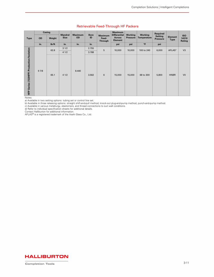
HFP
Seri
es
(722H
FP
) P
rod
uct
ion
/Iso
lati
on
9 7/8
62.83 1/2
8.440
2.7555 10,000 10,000 100 to 240 6,000 AFLAS® V3
4 1/2 3.788
65.1 4 1/2 3.562 6 15,000 15,000 68 to 300 5,800 HNBR V0
Notes:a) Available in two setting options: tubing set or control line set.b) Available in three releasing options: straight shift-and-pull method, knock-out plug-and-pump method, punch-and-pump method.c) Available in various metallurgy, elastomers, and thread connections to suit well conditions.d) Refer to individual specification sheets for additional details.Contact Halliburton for additional information.AFLAS® is a registered trademark of the Asahi Glass Co., Ltd.
Retrievable Feed-Through HF Packers
Type
CasingMandrel
SizeMaximum
ODBore
IDMaximum
Feed-Through
Maximum Differential
Across Element
Working Pressure
Working Temperature
Required Setting
PressureElement
Type
ISO 14310 Rating
OD Weight
in. lb/ft in. in. in. psi psi °F psi
Completion Solutions
3-12
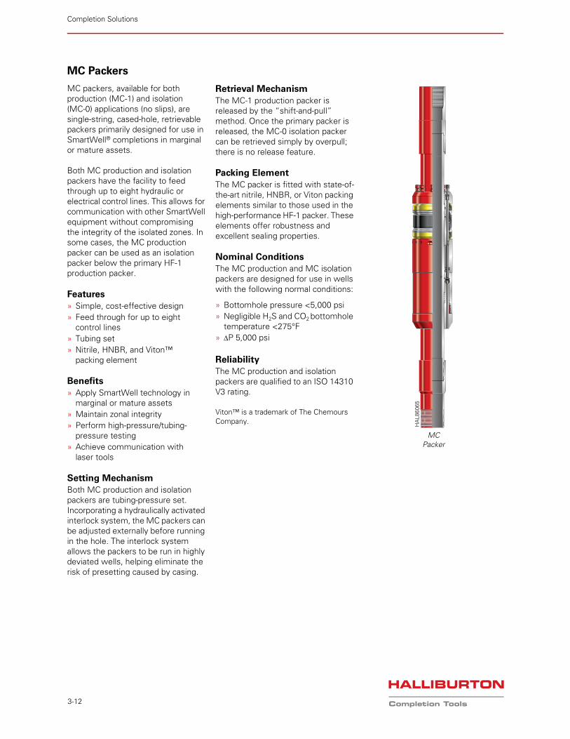
MC Packers
MC packers, available for both production (MC-1) and isolation (MC-0) applications (no slips), are single-string, cased-hole, retrievable packers primarily designed for use in SmartWell® completions in marginal or mature assets.
Both MC production and isolation packers have the facility to feed through up to eight hydraulic or electrical control lines. This allows for communication with other SmartWell equipment without compromising the integrity of the isolated zones. In some cases, the MC production packer can be used as an isolation packer below the primary HF-1 production packer.
Features» Simple, cost-effective design» Feed through for up to eight
control lines» Tubing set» Nitrile, HNBR, and Viton™
packing element
Benefits» Apply SmartWell technology in
marginal or mature assets» Maintain zonal integrity» Perform high-pressure/tubing-
pressure testing» Achieve communication with
laser tools
Setting MechanismBoth MC production and isolation packers are tubing-pressure set. Incorporating a hydraulically activated interlock system, the MC packers can be adjusted externally before running in the hole. The interlock system allows the packers to be run in highly deviated wells, helping eliminate the risk of presetting caused by casing.
Retrieval MechanismThe MC-1 production packer is released by the “shift-and-pull” method. Once the primary packer is released, the MC-0 isolation packer can be retrieved simply by overpull; there is no release feature.
Packing ElementThe MC packer is fitted with state-of-the-art nitrile, HNBR, or Viton packing elements similar to those used in the high-performance HF-1 packer. These elements offer robustness and excellent sealing properties.
Nominal ConditionsThe MC production and MC isolation packers are designed for use in wells with the following normal conditions:
» Bottomhole pressure <5,000 psi» Negligible H2S and CO2 bottomhole
temperature <275°F» P 5,000 psi
ReliabilityThe MC production and isolation packers are qualified to an ISO 14310 V3 rating.
Viton™ is a trademark of The Chemours Company.
MC Packer
HA
L860
65
Completion Solutions | Intelligent Completions
3-13
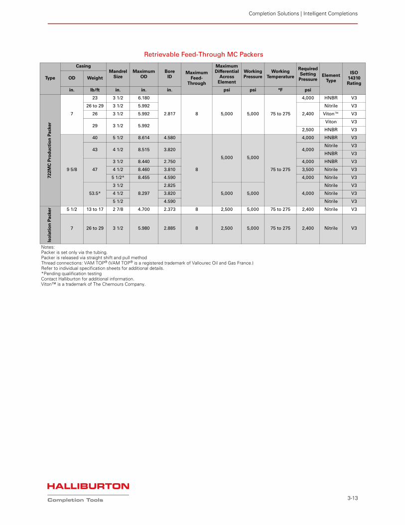
Retrievable Feed-Through MC Packers
Type
Casing Mandrel
SizeMaximum
ODBore
IDMaximum
Feed-Through
Maximum Differential
Across Element
Working Pressure
Working Temperature
Required Setting
PressureElement
Type
ISO 14310 Rating
OD Weight
in. lb/ft in. in. in. psi psi °F psi
722
MC
Pro
du
cti
on
Pa
cker
7
23 3 1/2 6.180
2.817 8 5,000 5,000 75 to 275
4,000 HNBR V3
26 to 29 3 1/2 5.992
2,400
Nitrile V3
26 3 1/2 5.992 Viton™ V3
29 3 1/2 5.992Viton V3
2,500 HNBR V3
9 5/8
40 5 1/2 8.614 4.580
8
5,000 5,000
75 to 275
4,000 HNBR V3
43 4 1/2 8.515 3.820 4,000Nitrile V3
HNBR V3
47
3 1/2 8.440 2.750 4,000 HNBR V3
4 1/2 8.460 3.810 3,500 Nitrile V3
5 1/2* 8.455 4.590 4,000 Nitrile V3
53.5*
3 1/2
8.297
2.825
5,000 5,000 4,000
Nitrile V3
4 1/2 3.820 Nitrile V3
5 1/2 4.590 Nitrile V3
Iso
lati
on
Pa
cke
r 5 1/2 13 to 17 2 7/8 4.700 2.373 8 2,500 5,000 75 to 275 2,400 Nitrile V3
7 26 to 29 3 1/2 5.980 2.885 8 2,500 5,000 75 to 275 2,400 Nitrile V3
Notes:Packer is set only via the tubing.Packer is released via straight shift and pull methodThread connections: VAM TOP® (VAM TOP® is a registered trademark of Vallourec Oil and Gas France.)Refer to individual specification sheets for additional details.*Pending qualification testingContact Halliburton for additional information.Viton™ is a trademark of The Chemours Company.
Completion Solutions
3-14
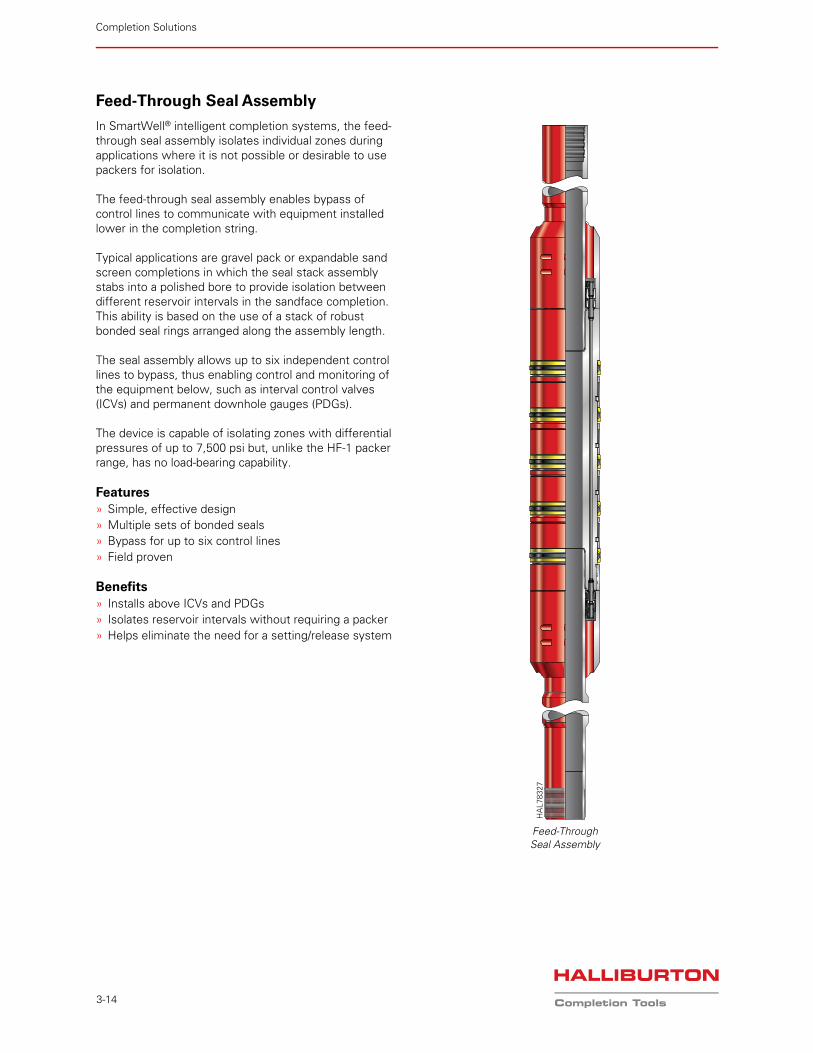
Feed-Through Seal Assembly
In SmartWell® intelligent completion systems, the feed-through seal assembly isolates individual zones during applications where it is not possible or desirable to use packers for isolation.
The feed-through seal assembly enables bypass of control lines to communicate with equipment installed lower in the completion string.
Typical applications are gravel pack or expandable sand screen completions in which the seal stack assembly stabs into a polished bore to provide isolation between different reservoir intervals in the sandface completion. This ability is based on the use of a stack of robust bonded seal rings arranged along the assembly length.
The seal assembly allows up to six independent control lines to bypass, thus enabling control and monitoring of the equipment below, such as interval control valves (ICVs) and permanent downhole gauges (PDGs).
The device is capable of isolating zones with differential pressures of up to 7,500 psi but, unlike the HF-1 packer range, has no load-bearing capability.
Features» Simple, effective design» Multiple sets of bonded seals» Bypass for up to six control lines» Field proven
Benefits» Installs above ICVs and PDGs» Isolates reservoir intervals without requiring a packer» Helps eliminate the need for a setting/release system
Feed-ThroughSeal Assembly
HA
L783
27
Completion Solutions | Intelligent Completions
3-15
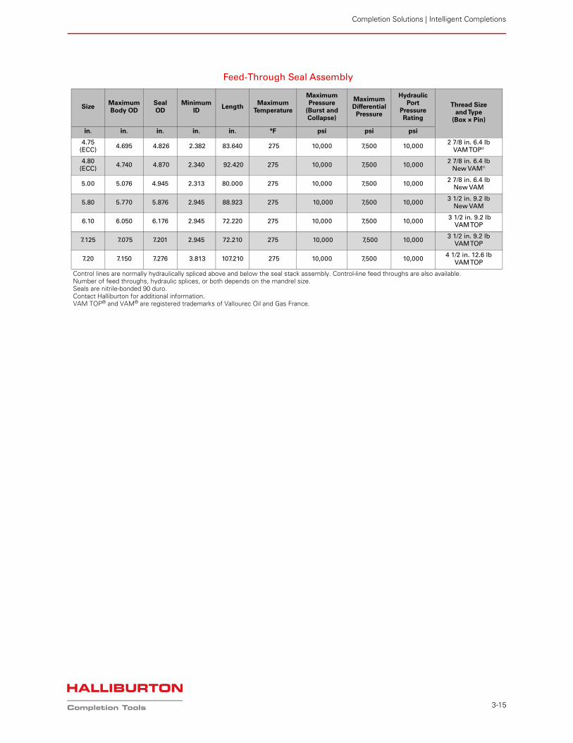
Feed-Through Seal Assembly
Size Maximum Body OD
Seal OD
Minimum ID
LengthMaximum
Temperature
MaximumPressure
(Burst and Collapse)
MaximumDifferential
Pressure
Hydraulic Port
Pressure Rating
Thread Size and Type
(Box × Pin)
in. in. in. in. in. °F psi psi psi
4.75 (ECC)
4.695 4.826 2.382 83.640 275 10,000 7,500 10,0002 7/8 in. 6.4 lb
VAM TOP®
4.80 (ECC)
4.740 4.870 2.340 92.420 275 10,000 7,500 10,000 2 7/8 in. 6.4 lb
New VAM®
5.00 5.076 4.945 2.313 80.000 275 10,000 7,500 10,0002 7/8 in. 6.4 lb
New VAM
5.80 5.770 5.876 2.945 88.923 275 10,000 7,500 10,000 3 1/2 in. 9.2 lb
New VAM
6.10 6.050 6.176 2.945 72.220 275 10,000 7,500 10,000 3 1/2 in. 9.2 lb
VAM TOP
7.125 7.075 7.201 2.945 72.210 275 10,000 7,500 10,0003 1/2 in. 9.2 lb
VAM TOP
7.20 7.150 7.276 3.813 107.210 275 10,000 7,500 10,0004 1/2 in. 12.6 lb
VAM TOP
Control lines are normally hydraulically spliced above and below the seal stack assembly. Control-line feed throughs are also available.Number of feed throughs, hydraulic splices, or both depends on the mandrel size.Seals are nitrile-bonded 90 duro.Contact Halliburton for additional information.VAM TOP® and VAM® are registered trademarks of Vallourec Oil and Gas France.
Completion Solutions
3-16
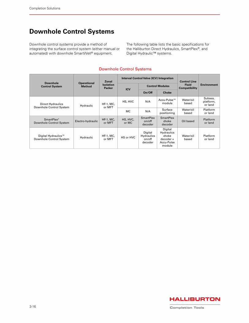
Downhole Control Systems
Downhole control systems provide a method of integrating the surface control system (either manual or automated) with downhole SmartWell® equipment.
The following table lists the basic specifications for the Halliburton Direct Hydraulics, SmartPlex®, and Digital Hydraulic™ systems.
Downhole Control Systems
Downhole Control System
Operational Method
Zonal Isolation Packer
Interval Control Valve (ICV) IntegrationControl Line
Fluid Compatibility
Environment
ICVControl Modules
On/Off Choke
Direct Hydraulics Downhole Control System
HydraulicHF-1, MC,
or MFT
HS, HVC N/AAccu-Pulse™
moduleWater/oil
based
Subsea, platform, or land
MC N/ASurface
positioningWater/oil
basedPlatform or land
SmartPlex® Downhole Control System
Electro-hydraulicHF-1, MC,
or MFTHS, HVC,
or MC
SmartPlex on/off
decoder
SmartPlex choke
decoderOil based
Platform or land
Digital Hydraulics™ Downhole Control System
HydraulicHF-1, MC,
or MFTHS or HVC
DigitalHydraulics
on/off decoder
DigitalHydraulics
choke decoder + Accu-Pulse
module
Water/oil based
Platform or land
Completion Solutions | Intelligent Completions
3-17
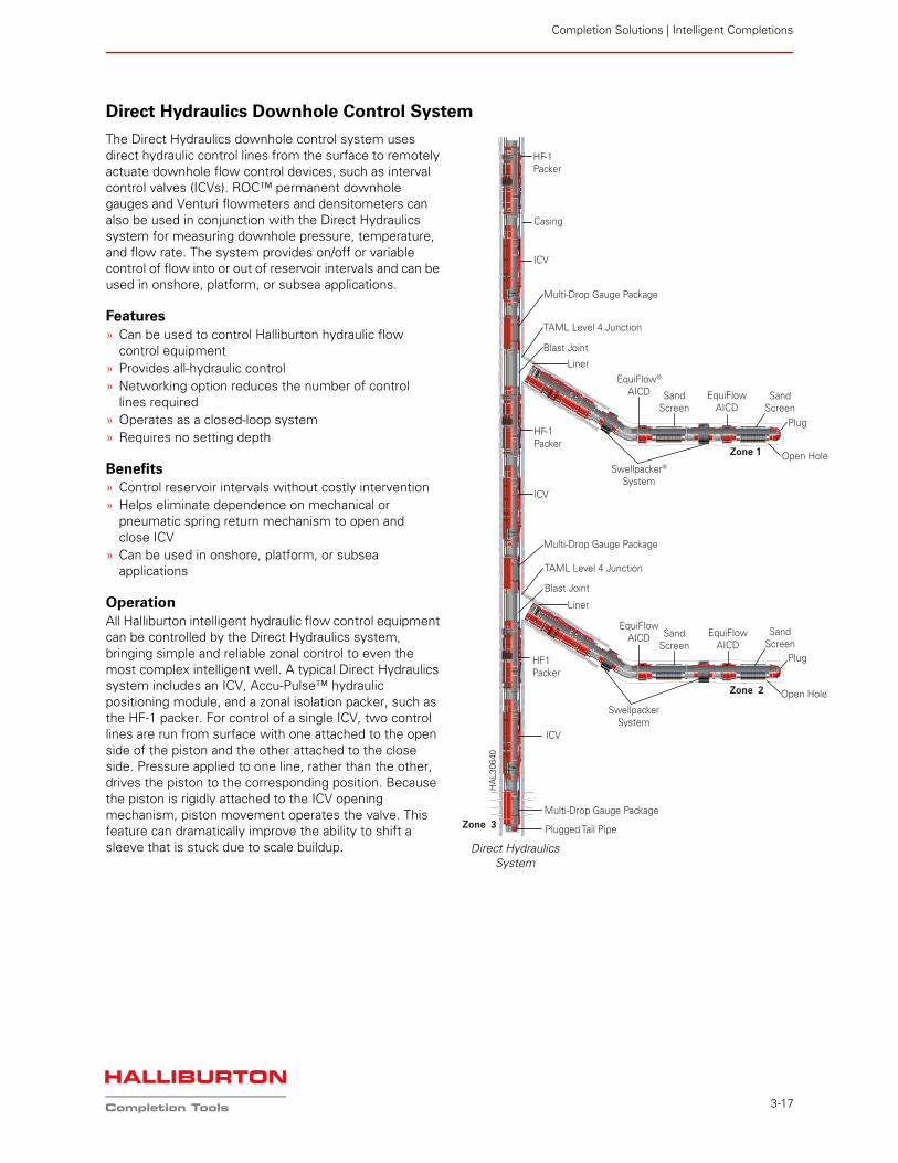
Direct Hydraulics Downhole Control System
The Direct Hydraulics downhole control system uses direct hydraulic control lines from the surface to remotely actuate downhole flow control devices, such as interval control valves (ICVs). ROC™ permanent downhole gauges and Venturi flowmeters and densitometers can also be used in conjunction with the Direct Hydraulics system for measuring downhole pressure, temperature, and flow rate. The system provides on/off or variable control of flow into or out of reservoir intervals and can be used in onshore, platform, or subsea applications.
Features» Can be used to control Halliburton hydraulic flow
control equipment» Provides all-hydraulic control» Networking option reduces the number of control
lines required» Operates as a closed-loop system» Requires no setting depth
Benefits» Control reservoir intervals without costly intervention» Helps eliminate dependence on mechanical or
pneumatic spring return mechanism to open and close ICV
» Can be used in onshore, platform, or subsea applications
OperationAll Halliburton intelligent hydraulic flow control equipment can be controlled by the Direct Hydraulics system, bringing simple and reliable zonal control to even the most complex intelligent well. A typical Direct Hydraulics system includes an ICV, Accu-Pulse™ hydraulic positioning module, and a zonal isolation packer, such as the HF-1 packer. For control of a single ICV, two control lines are run from surface with one attached to the open side of the piston and the other attached to the close side. Pressure applied to one line, rather than the other, drives the piston to the corresponding position. Because the piston is rigidly attached to the ICV opening mechanism, piston movement operates the valve. This feature can dramatically improve the ability to shift a sleeve that is stuck due to scale buildup.
HF-1Packer
ICV
Multi-Drop Gauge Package
Liner
Swellpacker® System
Blast Joint
TAML Level 4 Junction
Casing
HF-1Packer
ICV
Multi-Drop Gauge Package
HF1Packer
ICV
Multi-Drop Gauge Package
Plugged Tail Pipe
Liner
Blast Joint
TAML Level 4 Junction
EquiFlowAICD
Open Hole
Open Hole
SandScreen
SandScreen
Plug
Zone 1
Zone 2
Zone 3
Swellpacker System
EquiFlowAICD Sand
ScreenSand
ScreenPlug
EquiFlow®
AICD
EquiFlowAICD
Direct HydraulicsSystem
HA
L306
40
Completion Solutions
3-18
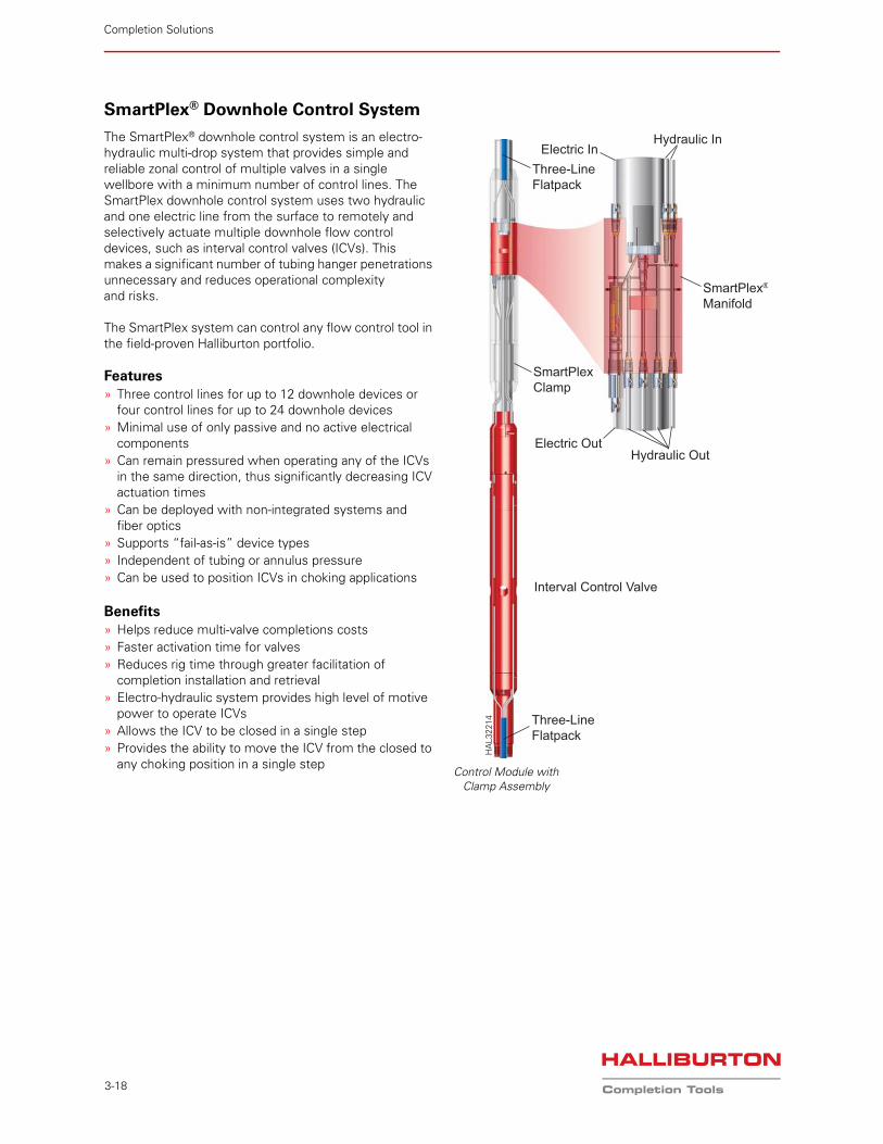
SmartPlex® Downhole Control System
The SmartPlex® downhole control system is an electro-hydraulic multi-drop system that provides simple and reliable zonal control of multiple valves in a single wellbore with a minimum number of control lines. The SmartPlex downhole control system uses two hydraulic and one electric line from the surface to remotely and selectively actuate multiple downhole flow control devices, such as interval control valves (ICVs). This makes a significant number of tubing hanger penetrations unnecessary and reduces operational complexity and risks.
The SmartPlex system can control any flow control tool in the field-proven Halliburton portfolio.
Features» Three control lines for up to 12 downhole devices or
four control lines for up to 24 downhole devices» Minimal use of only passive and no active electrical
components» Can remain pressured when operating any of the ICVs
in the same direction, thus significantly decreasing ICV actuation times
» Can be deployed with non-integrated systems andfiber optics
» Supports “fail-as-is” device types» Independent of tubing or annulus pressure» Can be used to position ICVs in choking applications
Benefits» Helps reduce multi-valve completions costs» Faster activation time for valves» Reduces rig time through greater facilitation of
completion installation and retrieval» Electro-hydraulic system provides high level of motive
power to operate ICVs» Allows the ICV to be closed in a single step» Provides the ability to move the ICV from the closed to
any choking position in a single step
Three-LineFlatpack
Electric InHydraulic In
SmartPlex®
Manifold
SmartPlexClamp
Electric OutHydraulic Out
Interval Control Valve
Three-LineFlatpack
Control Module withClamp Assembly
HA
L322
14
Completion Solutions | Intelligent Completions
3-19
ApplicationThe SmartPlex® downhole control system is applicable for any dry-tree multizone completion that requires more than two valves. When compared to the Direct Hydraulics system, the SmartPlex system not only helps reduce the overall costs of an intelligent completion, it also reduces the complexity involved by minimizing the number of control lines required.
The SmartPlex system is ideally suited for long horizontal, compartmentalized completions, in both cased or open hole, in which selective control of each interval is desired. Typically, this can be advantageous for selective stimulation control in tight-gas applications or in combination with a choking ICV for drawdown optimization in production applications.
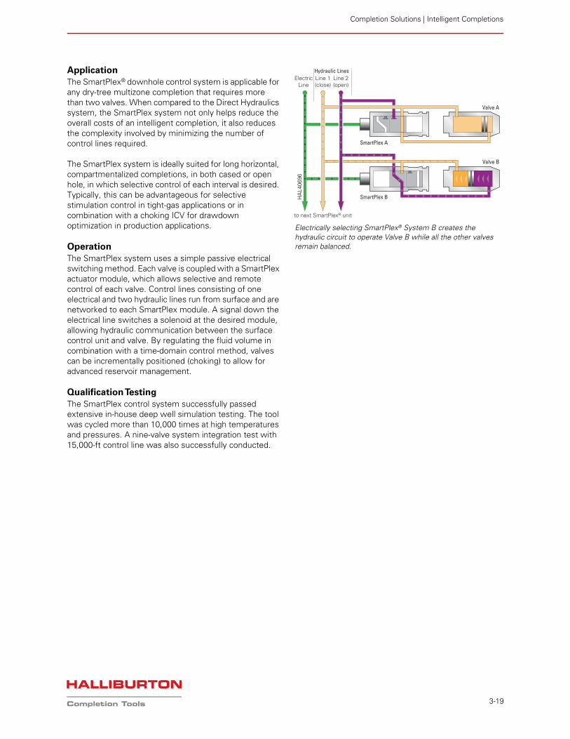
OperationThe SmartPlex system uses a simple passive electrical switching method. Each valve is coupled with a SmartPlex actuator module, which allows selective and remote control of each valve. Control lines consisting of one electrical and two hydraulic lines run from surface and are networked to each SmartPlex module. A signal down the electrical line switches a solenoid at the desired module, allowing hydraulic communication between the surface control unit and valve. By regulating the fluid volume in combination with a time-domain control method, valves can be incrementally positioned (choking) to allow for advanced reservoir management.
Qualification TestingThe SmartPlex control system successfully passed extensive in-house deep well simulation testing. The tool was cycled more than 10,000 times at high temperatures and pressures. A nine-valve system integration test with 15,000-ft control line was also successfully conducted.
Electrically selecting SmartPlex® System B creates the hydraulic circuit to operate Valve B while all the other valves remain balanced.
Line 1(close)
Line 2(open)
Hydraulic Lines
to next SmartPlex® unit
Valve A
Valve B
SmartPlex A
SmartPlex B
ElectricLine
HA
L406
96
Completion Solutions
3-20
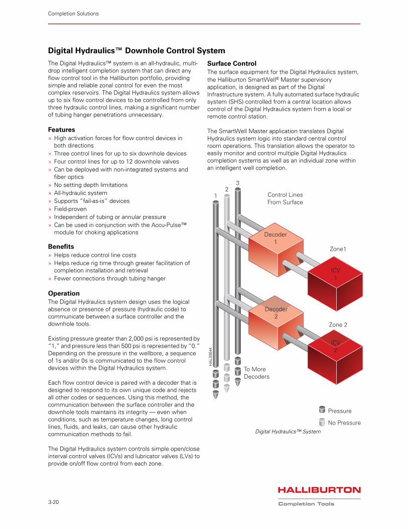
Digital Hydraulics™ Downhole Control System
The Digital Hydraulics™ system is an all-hydraulic, multi-drop intelligent completion system that can direct any flow control tool in the Halliburton portfolio, providing simple and reliable zonal control for even the most complex reservoirs. The Digital Hydraulics system allows up to six flow control devices to be controlled from only three hydraulic control lines, making a significant number of tubing hanger penetrations unnecessary.
Features» High activation forces for flow control devices in
both directions» Three control lines for up to six downhole devices» Four control lines for up to 12 downhole valves» Can be deployed with non-integrated systems and
fiber optics» No setting depth limitations» All-hydraulic system» Supports “fail-as-is” devices» Field-proven» Independent of tubing or annular pressure» Can be used in conjunction with the Accu-Pulse™
module for choking applications
Benefits» Helps reduce control line costs» Helps reduce rig time through greater facilitation of
completion installation and retrieval» Fewer connections through tubing hanger
OperationThe Digital Hydraulics system design uses the logical absence or presence of pressure (hydraulic code) to communicate between a surface controller and the downhole tools.
Existing pressure greater than 2,000 psi is represented by “1,” and pressure less than 500 psi is represented by “0.” Depending on the pressure in the wellbore, a sequence of 1s and/or 0s is communicated to the flow control devices within the Digital Hydraulics system.
Each flow control device is paired with a decoder that is designed to respond to its own unique code and rejects all other codes or sequences. Using this method, the communication between the surface controller and the downhole tools maintains its integrity — even when conditions, such as temperature changes, long control lines, fluids, and leaks, can cause other hydraulic communication methods to fail.
The Digital Hydraulics system controls simple open/close interval control valves (ICVs) and lubricator valves (LVs) to provide on/off flow control from each zone.
Surface ControlThe surface equipment for the Digital Hydraulics system, the Halliburton SmartWell® Master supervisory application, is designed as part of the Digital Infrastructure system. A fully automated surface hydraulic system (SHS) controlled from a central location allows control of the Digital Hydraulics system from a local or remote control station.
The SmartWell Master application translates Digital Hydraulics system logic into standard central control room operations. This translation allows the operator to easily monitor and control multiple Digital Hydraulics completion systems as well as an individual zone within an intelligent well completion.
Digital Hydraulics™ System
Decoder1
Zone1
Zone 2
ICV1
Decoder2
ICV2
Control LinesFrom Surface
To MoreDecoders
12
3
Pressure
No Pressure
HA
L306
44
Completion Solutions | Intelligent Completions
3-21
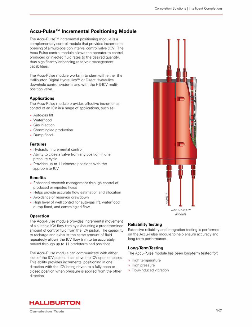
Accu-Pulse™ Incremental Positioning Module
The Accu-Pulse™ incremental positioning module is a complementary control module that provides incremental opening of a multi-position interval control valve (ICV). The Accu-Pulse control module allows the operator to control produced or injected fluid rates to the desired quantity, thus significantly enhancing reservoir management capabilities.
The Accu-Pulse module works in tandem with either the Halliburton Digital Hydraulics™ or Direct Hydraulics downhole control systems and with the HS-ICV multi-position valve.
ApplicationsThe Accu-Pulse module provides effective incremental control of an ICV in a range of applications, such as:
» Auto-gas lift» Waterflood» Gas injection» Commingled production» Dump flood
Features» Hydraulic, incremental control» Ability to close a valve from any position in one
pressure cycle» Provides up to 11 discrete positions with the
appropriate ICV
Benefits» Enhanced reservoir management through control of
produced or injected fluids» Helps provide accurate flow estimation and allocation» Avoidance of reservoir drawdown» High level of well control for auto-gas lift, waterflood,
dump flood, and commingled flow
OperationThe Accu-Pulse module provides incremental movement of a suitable ICV flow trim by exhausting a predetermined amount of control fluid from the ICV piston. The capability to recharge and exhaust the same amount of fluid repeatedly allows the ICV flow trim to be accurately moved through up to 11 predetermined positions.
The Accu-Pulse module can communicate with either side of the ICV piston. It can drive the ICV open or closed. This ability provides incremental positioning in one direction with the ICV being driven to a fully open or closed position when pressure is applied from the other direction.
Reliability TestingExtensive reliability and integration testing is performed on the Accu-Pulse module to help ensure accuracy and long-term performance.
Long-Term TestingThe Accu-Pulse module has been long-term tested for:
» High temperature» High pressure» Flow-induced vibration
Accu-Pulse™ Module
HA
L983
77
Completion Solutions
3-22
Auxiliary Components
Control-Line Cut Sub
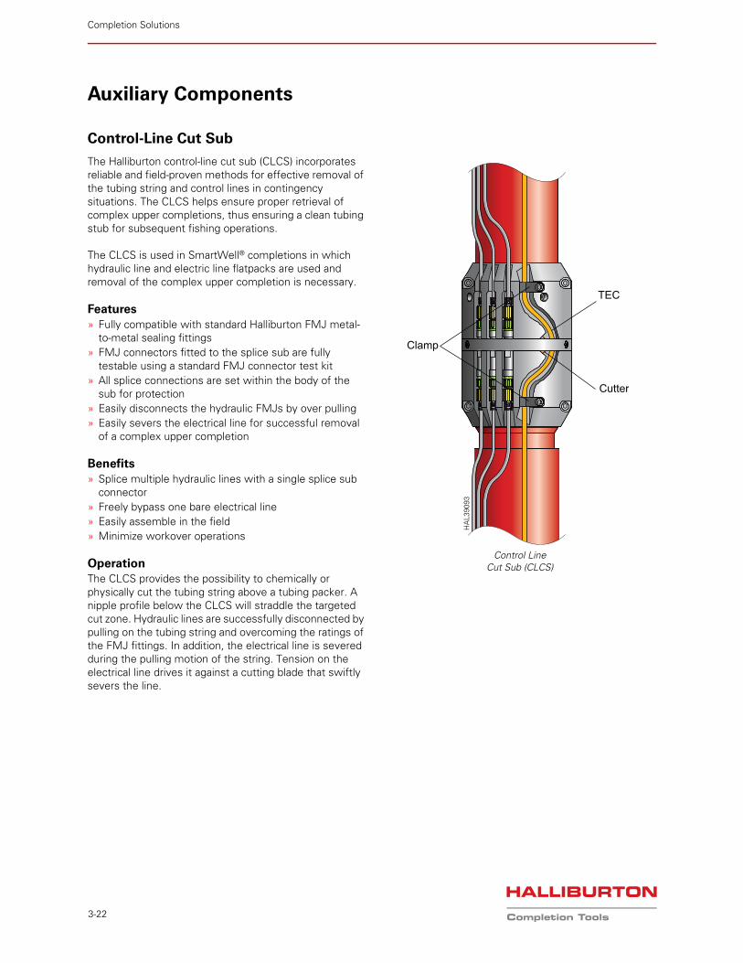
The Halliburton control-line cut sub (CLCS) incorporates reliable and field-proven methods for effective removal of the tubing string and control lines in contingency situations. The CLCS helps ensure proper retrieval of complex upper completions, thus ensuring a clean tubing stub for subsequent fishing operations.
The CLCS is used in SmartWell® completions in which hydraulic line and electric line flatpacks are used and removal of the complex upper completion is necessary.
Features» Fully compatible with standard Halliburton FMJ metal-
to-metal sealing fittings» FMJ connectors fitted to the splice sub are fully
testable using a standard FMJ connector test kit» All splice connections are set within the body of the
sub for protection» Easily disconnects the hydraulic FMJs by over pulling » Easily severs the electrical line for successful removal
of a complex upper completion
Benefits» Splice multiple hydraulic lines with a single splice sub
connector» Freely bypass one bare electrical line » Easily assemble in the field» Minimize workover operations
OperationThe CLCS provides the possibility to chemically or physically cut the tubing string above a tubing packer. A nipple profile below the CLCS will straddle the targeted cut zone. Hydraulic lines are successfully disconnected by pulling on the tubing string and overcoming the ratings of the FMJ fittings. In addition, the electrical line is severed during the pulling motion of the string. Tension on the electrical line drives it against a cutting blade that swiftly severs the line.
Clamp
TEC
Cutter
HA
L390
93
Control LineCut Sub (CLCS)
Completion Solutions | Intelligent Completions
3-23
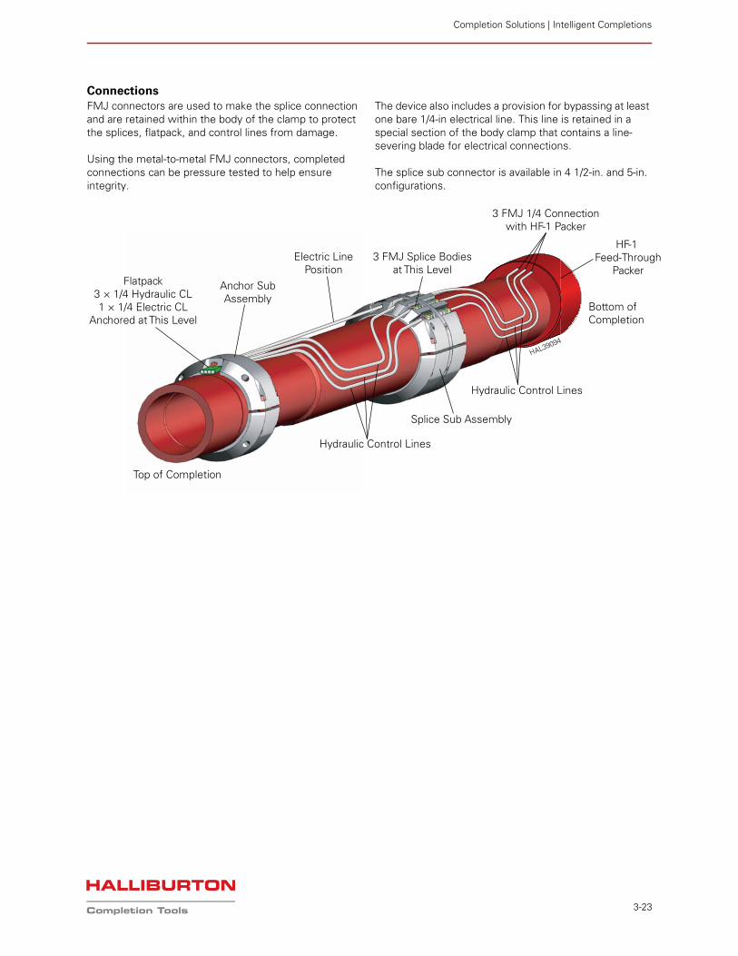
ConnectionsFMJ connectors are used to make the splice connection and are retained within the body of the clamp to protect the splices, flatpack, and control lines from damage.
Using the metal-to-metal FMJ connectors, completed connections can be pressure tested to help ensure integrity.
The device also includes a provision for bypassing at least one bare 1/4-in electrical line. This line is retained in a special section of the body clamp that contains a line-severing blade for electrical connections.
The splice sub connector is available in 4 1/2-in. and 5-in. configurations.
Electric LinePosition
Anchor SubAssembly
3 FMJ Splice Bodiesat This Level
Splice Sub Assembly
Hydraulic Control Lines
Hydraulic Control Lines
3 FMJ 1/4 Connectionwith HF-1 Packer
Bottom ofCompletion
Top of Completion
HF-1 Feed-Through
PackerFlatpack
3 × 1/4 Hydraulic CL1 × 1/4 Electric CL
Anchored at This Level
HAL39094
Completion Solutions
3-24
Splice Clamp/Sub
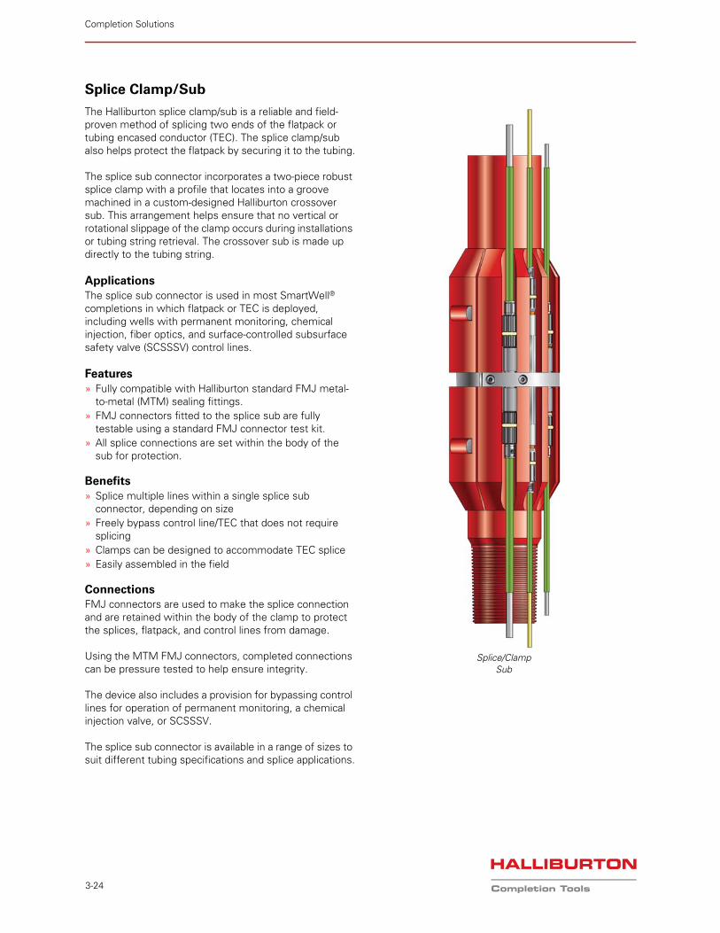
The Halliburton splice clamp/sub is a reliable and field-proven method of splicing two ends of the flatpack or tubing encased conductor (TEC). The splice clamp/sub also helps protect the flatpack by securing it to the tubing.
The splice sub connector incorporates a two-piece robust splice clamp with a profile that locates into a groove machined in a custom-designed Halliburton crossover sub. This arrangement helps ensure that no vertical or rotational slippage of the clamp occurs during installations or tubing string retrieval. The crossover sub is made up directly to the tubing string.
ApplicationsThe splice sub connector is used in most SmartWell® completions in which flatpack or TEC is deployed, including wells with permanent monitoring, chemical injection, fiber optics, and surface-controlled subsurface safety valve (SCSSSV) control lines.
Features» Fully compatible with Halliburton standard FMJ metal-
to-metal (MTM) sealing fittings.» FMJ connectors fitted to the splice sub are fully
testable using a standard FMJ connector test kit.» All splice connections are set within the body of the
sub for protection.
Benefits» Splice multiple lines within a single splice sub
connector, depending on size» Freely bypass control line/TEC that does not require
splicing» Clamps can be designed to accommodate TEC splice» Easily assembled in the field
ConnectionsFMJ connectors are used to make the splice connection and are retained within the body of the clamp to protect the splices, flatpack, and control lines from damage.
Using the MTM FMJ connectors, completed connections can be pressure tested to help ensure integrity.
The device also includes a provision for bypassing control lines for operation of permanent monitoring, a chemical injection valve, or SCSSSV.
The splice sub connector is available in a range of sizes to suit different tubing specifications and splice applications.
Splice/ClampSub
Completion Solutions | Intelligent Completions
3-25
Splice Sub
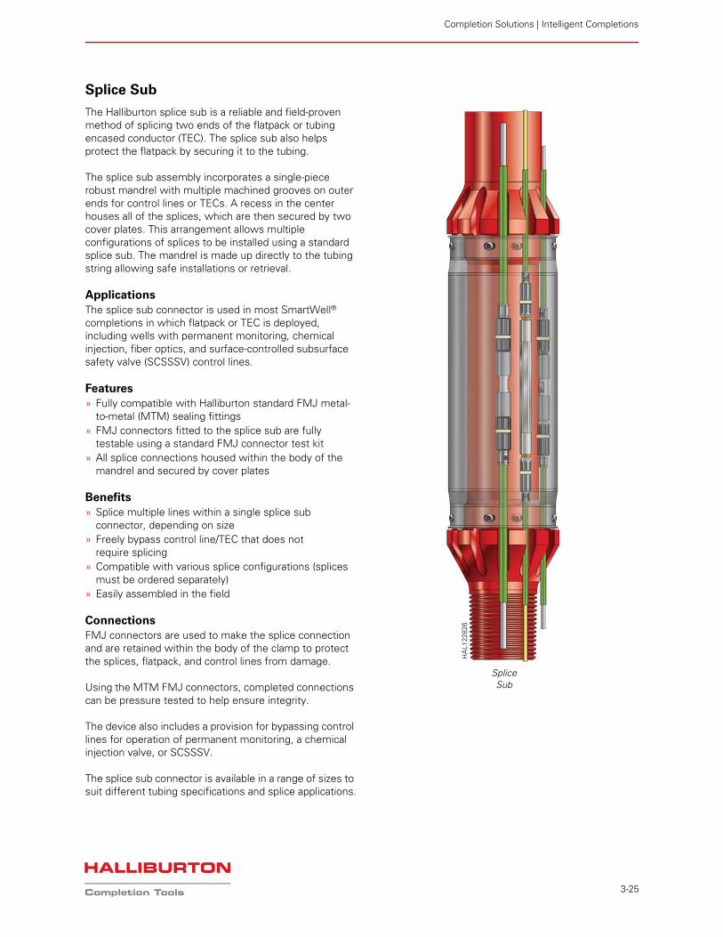
The Halliburton splice sub is a reliable and field-proven method of splicing two ends of the flatpack or tubing encased conductor (TEC). The splice sub also helps protect the flatpack by securing it to the tubing.
The splice sub assembly incorporates a single-piece robust mandrel with multiple machined grooves on outer ends for control lines or TECs. A recess in the center houses all of the splices, which are then secured by two cover plates. This arrangement allows multiple configurations of splices to be installed using a standard splice sub. The mandrel is made up directly to the tubing string allowing safe installations or retrieval.
ApplicationsThe splice sub connector is used in most SmartWell® completions in which flatpack or TEC is deployed, including wells with permanent monitoring, chemical injection, fiber optics, and surface-controlled subsurface safety valve (SCSSSV) control lines.
Features» Fully compatible with Halliburton standard FMJ metal-
to-metal (MTM) sealing fittings» FMJ connectors fitted to the splice sub are fully
testable using a standard FMJ connector test kit» All splice connections housed within the body of the
mandrel and secured by cover plates
Benefits» Splice multiple lines within a single splice sub
connector, depending on size» Freely bypass control line/TEC that does not
require splicing» Compatible with various splice configurations (splices
must be ordered separately)» Easily assembled in the field
ConnectionsFMJ connectors are used to make the splice connection and are retained within the body of the clamp to protect the splices, flatpack, and control lines from damage.
Using the MTM FMJ connectors, completed connections can be pressure tested to help ensure integrity.
The device also includes a provision for bypassing control lines for operation of permanent monitoring, a chemical injection valve, or SCSSSV.
The splice sub connector is available in a range of sizes to suit different tubing specifications and splice applications.
SpliceSub
HA
L122
826
Completion Solutions
3-26
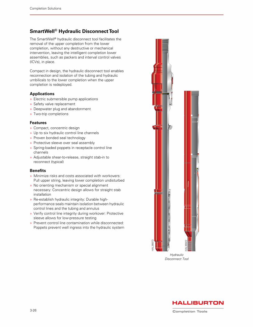
SmartWell® Hydraulic Disconnect Tool
The SmartWell® hydraulic disconnect tool facilitates the removal of the upper completion from the lower completion, without any destructive or mechanical intervention, leaving the intelligent completion lower assemblies, such as packers and interval control valves (ICVs), in place.
Compact in design, the hydraulic disconnect tool enables reconnection and isolation of the tubing and hydraulic umbilicals to the lower completion when the upper completion is redeployed.
Applications» Electric submersible pump applications» Safety valve replacement» Deepwater plug and abandonment» Two-trip completions
Features» Compact, concentric design» Up to six hydraulic control line channels» Proven bonded seal technology» Protective sleeve over seal assembly» Spring-loaded poppets in receptacle control line
channels» Adjustable shear-to-release, straight stab-in to
reconnect (typical)
Benefits» Minimize risks and costs associated with workovers:
Pull upper string, leaving lower completion undisturbed» No orienting mechanism or special alignment
necessary: Concentric design allows for straight stab installation
» Re-establish hydraulic integrity: Durable high-performance seals maintain isolation between hydraulic control lines and the tubing and annulus
» Verify control line integrity during workover: Protective sleeve allows for low-pressure testing
» Prevent control line contamination while disconnected: Poppets prevent well ingress into the hydraulic system
HydraulicDisconnect Tool
HA
L369
22
HA
L368
73
Completion Solutions | Intelligent Completions
3-27
OperationThe hydraulic disconnect tool features six hydraulic control line channels that provide communication in a SmartWell® completion.
All six channels are independent of each other, using concentric seal channels that eliminate the need for special orientation.
While running the upper assembly, a protective sleeve covers the seals, preventing damage and providing a means to verify hydraulic control line integrity. The sleeve is engaged during stab-in, sliding up the seal assembly to safely present the seals in the receptacle.
While disconnected, spring-loaded poppets provide a debris barrier for the control line channels. The poppets are lifted off seat by the seal mandrel during stab-in, establishing hydraulic communication from the surface.
The secure latching mechanism can be configured on location to complement the customer well plan. Three modes of operation are available:
» Snap latch: Snap in/snap out» Anchor: Snap in/rotate out to release» Shear anchor: Snap in/shear to release
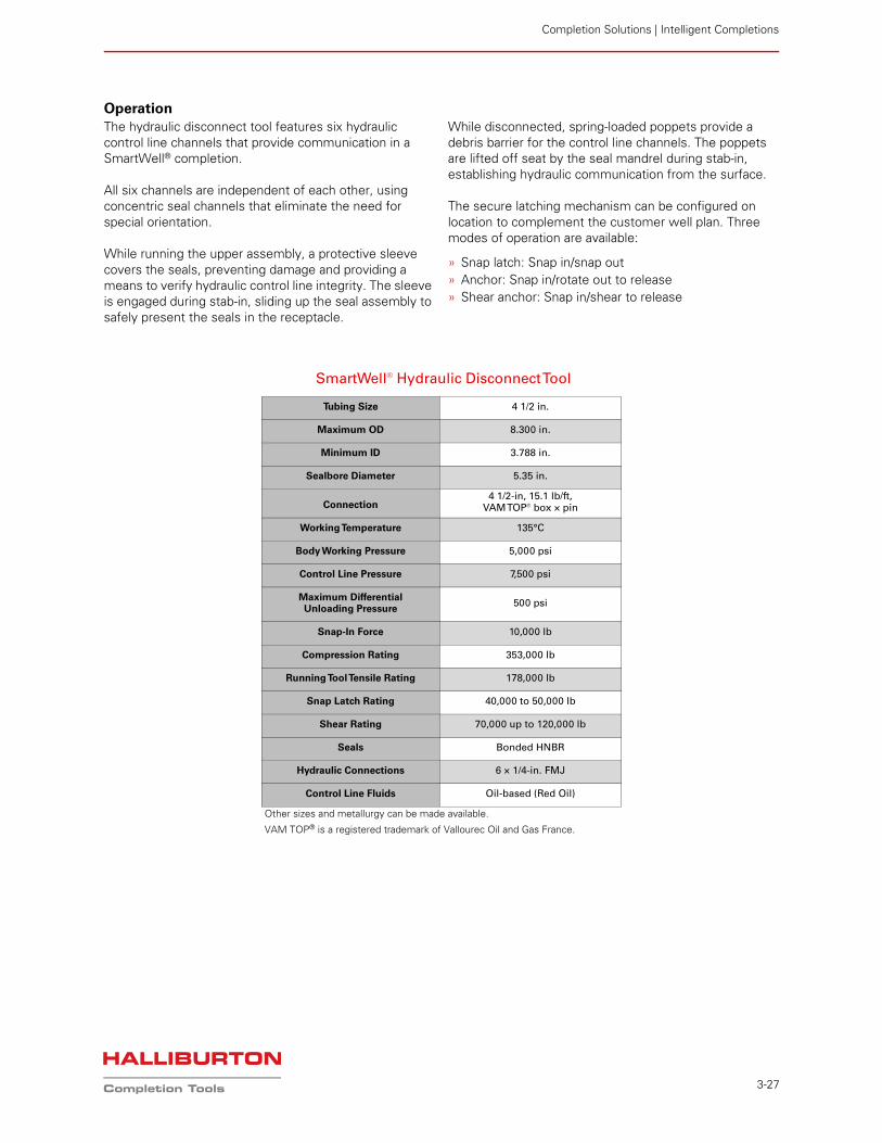
SmartWell® Hydraulic Disconnect Tool
Tubing Size 4 1/2 in.
Maximum OD 8.300 in.
Minimum ID 3.788 in.
Sealbore Diameter 5.35 in.
Connection 4 1/2-in, 15.1 lb/ft,
VAM TOP® box × pin
Working Temperature 135°C
Body Working Pressure 5,000 psi
Control Line Pressure 7,500 psi
Maximum Differential Unloading Pressure
500 psi
Snap-In Force 10,000 lb
Compression Rating 353,000 lb
Running Tool Tensile Rating 178,000 lb
Snap Latch Rating 40,000 to 50,000 lb
Shear Rating 70,000 up to 120,000 lb
Seals Bonded HNBR
Hydraulic Connections 6 × 1/4-in. FMJ
Control Line Fluids Oil-based (Red Oil)
Other sizes and metallurgy can be made available.
VAM TOP® is a registered trademark of Vallourec Oil and Gas France.
Completion Solutions
3-28
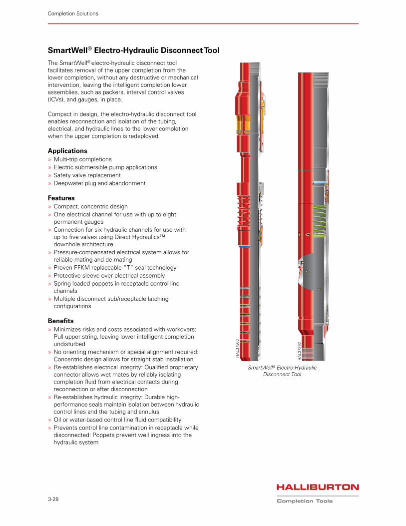
SmartWell® Electro-Hydraulic Disconnect Tool
The SmartWell® electro-hydraulic disconnect tool facilitates removal of the upper completion from the lower completion, without any destructive or mechanical intervention, leaving the intelligent completion lower assemblies, such as packers, interval control valves (ICVs), and gauges, in place.
Compact in design, the electro-hydraulic disconnect tool enables reconnection and isolation of the tubing, electrical, and hydraulic lines to the lower completion when the upper completion is redeployed.
Applications» Multi-trip completions» Electric submersible pump applications» Safety valve replacement» Deepwater plug and abandonment
Features» Compact, concentric design» One electrical channel for use with up to eight
permanent gauges» Connection for six hydraulic channels for use with
up to five valves using Direct Hydraulics™ downhole architecture
» Pressure-compensated electrical system allows for reliable mating and de-mating
» Proven FFKM replaceable “T” seal technology» Protective sleeve over electrical assembly» Spring-loaded poppets in receptacle control line
channels» Multiple disconnect sub/receptacle latching
configurations
Benefits» Minimizes risks and costs associated with workovers:
Pull upper string, leaving lower intelligent completion undisturbed
» No orienting mechanism or special alignment required: Concentric design allows for straight stab installation
» Re-establishes electrical integrity: Qualified proprietary connector allows wet mates by reliably isolating completion fluid from electrical contacts during reconnection or after disconnection
» Re-establishes hydraulic integrity: Durable high-performance seals maintain isolation between hydraulic control lines and the tubing and annulus
» Oil or water-based control line fluid compatibility» Prevents control line contamination in receptacle while
disconnected: Poppets prevent well ingress into the hydraulic system
SmartWell® Electro-HydraulicDisconnect Tool
HA
L373
62
HA
L373
63
Completion Solutions | Intelligent Completions
3-29
OperationThe electro-hydraulic disconnect tool features six hydraulic control line channels that provide hydraulic communication, and one electrical channel that provides gauge communication in a SmartWell® system completion. All six hydraulic channels are independent of each other, using concentric FFKM “T” seal channels that help ensure compatibility across most wellbore and control-line fluids and eliminate the need for special orientation.
The disconnect sub is run to depth, remaining centralized as it enters the disconnect receptacle. The stabbing sequence results in the protective electrical sleeves moving out of the way. The sub shoulders out against the receptacle. In this state, the electrical contacts are completely mated with each other. The electrical contact on the sub uses a canted spring to help ensure reliable mating, regardless of radial tolerances. Elastomeric pillow seals isolate wellbore fluids from the electrical connector. The electrical connector is pressure compensated to the annulus. Upon pulling out of the hole, the sub disengages from the receptacle, and the sleeves retract to their original position via springs, thus isolating the connectors from the environment.
In the disconnect receptacle, spring-loaded balls maintain a debris barrier to help prevent contamination of the lower completion hydraulic channels. As the disconnect sub enters the receptacle, it safely lifts the poppets off seat. The poppet springs are designed for an optimum force that prevents any damage to the seals. The sub continues into the disconnect receptacle until the latching mechanism is engaged and the sub shoulders out on the receptacle. In this mated state, the hydraulic seals reliably isolate annulus-to-tubing and hydraulic channels.
The secure latching mechanism can be configured in the region to complement the customer well plan. Three modes of operation are available:
» Snap latch: Snap in/snap out» Anchor: Snap in/rotate out to release» Shear: Snap in/shear to release
SmartWell® Electro-Hydraulic Disconnect Tool
Tubing Size 3 1/2 in.
Maximum OD 5.950 in.
Minimum ID 2.890 in.
Connection 3 1/2-in. 10.2 lb/ft VAM TOP® box × pin
Working Temperature 257°F (125°C)
Working Pressure 5,000 psi
Control Line Pressure 7,500 psi
Maximum Differential Unloading Pressure 500 psi (Hydraulic channel to tubing or annulus)
Snap-In Force 7,500 lb
Maximum Compression Rating 233,000 lb
Maximum Tensile Rating 114,000 lb
Shear Rating 70,000 lb (standard); Other sizes available on request
Seals Open Gland “T” Seal (FFKM) - field replaceable
Electrical Connection 1 × 1/4-in. E-FMJ
Hydraulic Connections 6 × 1/8-in. NPT
Control Line Fluids Oil- or water-based fluids
VAM TOP® is a registered trademark of Vallourec Oil and Gas France.
Completion Solutions
3-30
Permanent Monitoring
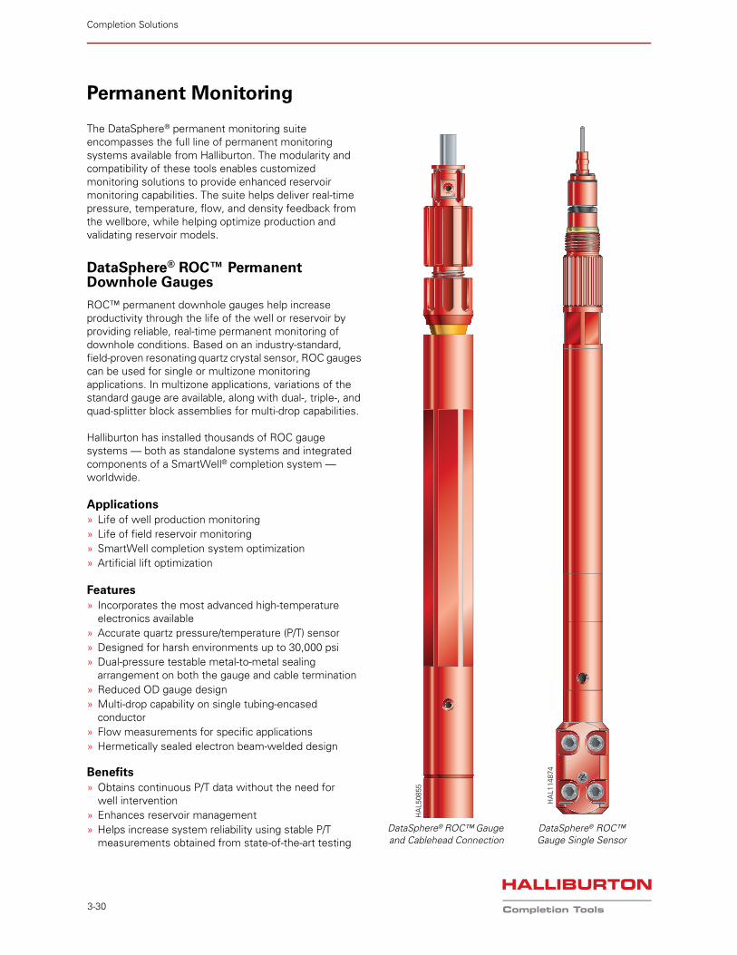
The DataSphere® permanent monitoring suite encompasses the full line of permanent monitoring systems available from Halliburton. The modularity and compatibility of these tools enables customized monitoring solutions to provide enhanced reservoir monitoring capabilities. The suite helps deliver real-time pressure, temperature, flow, and density feedback from the wellbore, while helping optimize production and validating reservoir models.
DataSphere® ROC™ Permanent Downhole Gauges
ROC™ permanent downhole gauges help increase productivity through the life of the well or reservoir by providing reliable, real-time permanent monitoring of downhole conditions. Based on an industry-standard, field-proven resonating quartz crystal sensor, ROC gauges can be used for single or multizone monitoring applications. In multizone applications, variations of the standard gauge are available, along with dual-, triple-, and quad-splitter block assemblies for multi-drop capabilities.
Halliburton has installed thousands of ROC gauge systems — both as standalone systems and integrated components of a SmartWell® completion system — worldwide.
Applications» Life of well production monitoring» Life of field reservoir monitoring» SmartWell completion system optimization» Artificial lift optimization
Features» Incorporates the most advanced high-temperature
electronics available » Accurate quartz pressure/temperature (P/T) sensor» Designed for harsh environments up to 30,000 psi» Dual-pressure testable metal-to-metal sealing
arrangement on both the gauge and cable termination» Reduced OD gauge design» Multi-drop capability on single tubing-encased
conductor» Flow measurements for specific applications» Hermetically sealed electron beam-welded design
Benefits» Obtains continuous P/T data without the need for
well intervention» Enhances reservoir management» Helps increase system reliability using stable P/T
measurements obtained from state-of-the-art testingDataSphere® ROC™ Gauge Single Sensor
DataSphere® ROC™ Gauge and Cablehead Connection
HA
L508
55
HA
L114
874
Completion Solutions | Intelligent Completions
3-31
ROC™ Gauge Designs» Quartz transducer» Hybrid technology» Maximum 200°C operating temperature» Multi-drop capability — up to eight gauges at 30,000 ft
downhole cable» Dual sensor feed-through capability» Improved shock and vibration performance» 0.75-in. OD slimline design available
Mechanical ArrangementThe DataSphere® ROC™ gauge mechanical arrangement comprises all “wetted” parts manufactured from high-performance, NACE-compliant corrosion-resistant alloys.
Cable TerminationThe FMJ cable termination has a pressure-testable, dual metal-to-metal ferrule seal arrangement that isolates the downhole cable outer metal sheath from the well fluid.
TestingThe complete DataSphere ROC gauge (sensor and electronic boards) is independently calibration-checked at the manufacturing facility. A calibration certificate is included with each gauge and provided before each installation.
New gauge designs are subjected to a highly accelerated lifetime test (HALT) program. This program is a series of controlled environmental stresses designed to help ensure stringent criteria are met for thermal shock, mechanical shock, vibration, and thermal aging.
During manufacture, all ROC gauges are also subjected to environmental stress screening to highlight any defect in functionality before installation at the wellsite. This screening method has proven far more effective than “burn-in” techniques. All gauges are further subjected to pressure tests at elevated temperatures during factory acceptance testing. Reliability testing demonstrated 13.55 years at 150°C, which exceeded the target reliability of 10 years at 150°C.
For more information on any of the details featured here, please email us at [email protected].
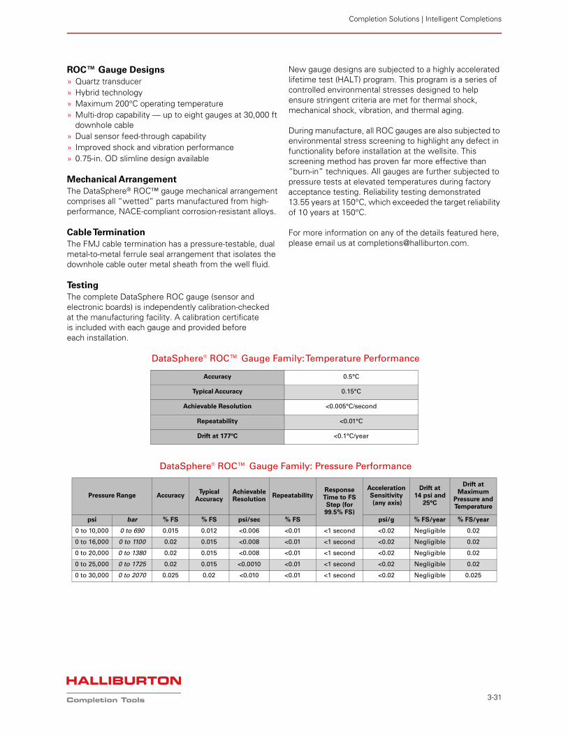
DataSphere® ROC™ Gauge Family: Temperature Performance
Accuracy 0.5°C
Typical Accuracy 0.15°C
Achievable Resolution <0.005°C/second
Repeatability <0.01°C
Drift at 177ºC <0.1°C/year
DataSphere® ROC™ Gauge Family: Pressure Performance
Pressure Range Accuracy Typical
AccuracyAchievable Resolution
Repeatability Response Time to FS Step (for 99.5% FS)
Acceleration Sensitivity (any axis)
Drift at 14 psi and
25°C
Drift at Maximum
Pressure and Temperature
psi bar % FS % FS psi/sec % FS psi/g % FS/year % FS/year
0 to 10,000 0 to 690 0.015 0.012 <0.006 <0.01 <1 second <0.02 Negligible 0.02
0 to 16,000 0 to 1100 0.02 0.015 <0.008 <0.01 <1 second <0.02 Negligible 0.02
0 to 20,000 0 to 1380 0.02 0.015 <0.008 <0.01 <1 second <0.02 Negligible 0.02
0 to 25,000 0 to 1725 0.02 0.015 <0.0010 <0.01 <1 second <0.02 Negligible 0.02
0 to 30,000 0 to 2070 0.025 0.02 <0.010 <0.01 <1 second <0.02 Negligible 0.025
Completion Solutions
3-32
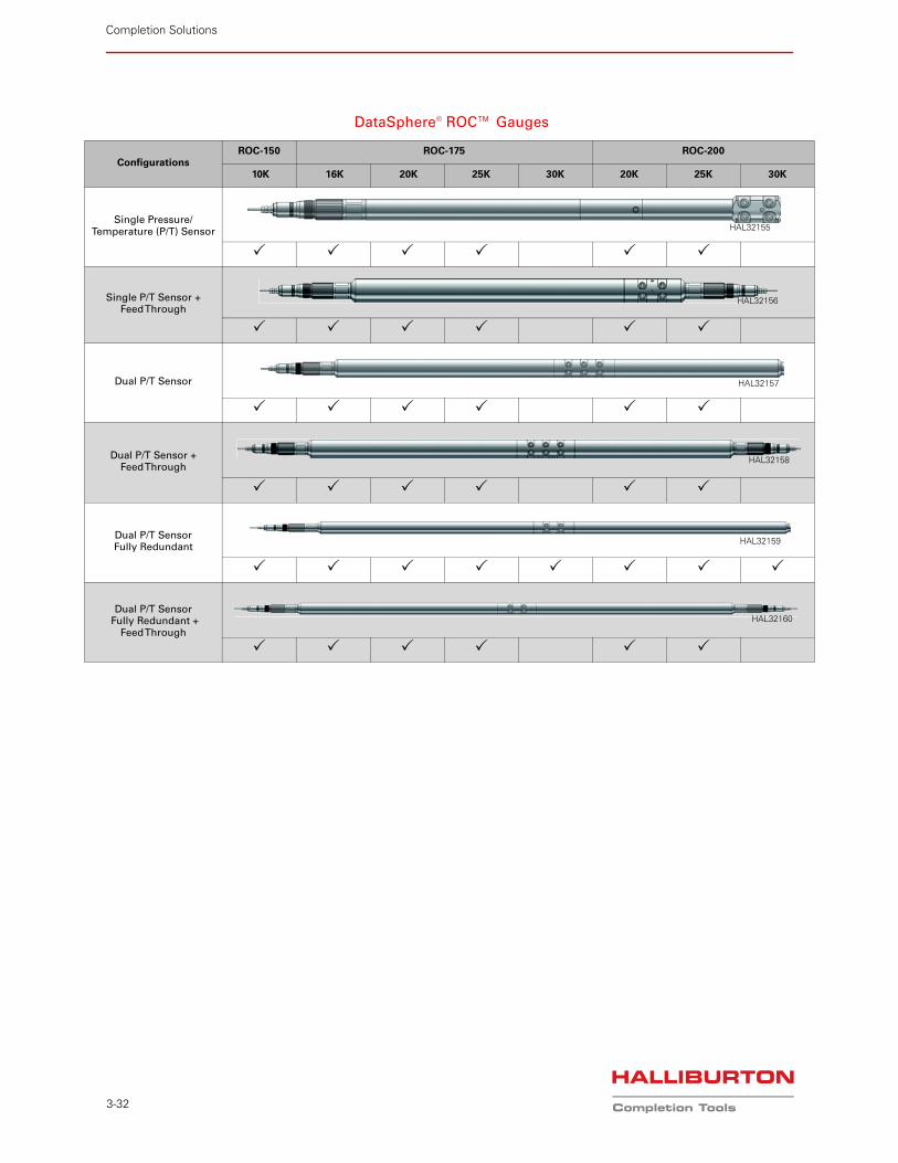
DataSphere® ROC™ Gauges
ConfigurationsROC-150 ROC-175 ROC-200
10K 16K 20K 25K 30K 20K 25K 30K
Single Pressure/Temperature (P/T) Sensor
Single P/T Sensor +Feed Through
Dual P/T Sensor
Dual P/T Sensor +Feed Through
Dual P/T SensorFully Redundant
Dual P/T Sensor Fully Redundant +
Feed Through
HAL32155
HAL32156
HAL32157
HAL32158
HAL32159
HAL32160
Completion Solutions | Intelligent Completions
3-33
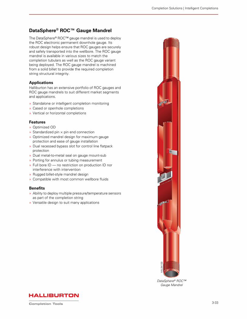
DataSphere® ROC™ Gauge Mandrel
The DataSphere® ROC™ gauge mandrel is used to deploy the ROC electronic permanent downhole gauge. Its robust design helps ensure that ROC gauges are securely and safely transported into the wellbore. The ROC gauge mandrel is available in various sizes to match the completion tubulars as well as the ROC gauge variant being deployed. The ROC gauge mandrel is machined from a solid billet to provide the required completion string structural integrity.
ApplicationsHalliburton has an extensive portfolio of ROC gauges and ROC gauge mandrels to suit different market segments and applications.
» Standalone or intelligent completion monitoring» Cased or openhole completions» Vertical or horizontal completions
Features» Optimized OD» Standardized pin × pin end connection» Optimized mandrel design for maximum gauge
protection and ease of gauge installation» Dual recessed bypass slot for control line flatpack
protection» Dual metal-to-metal seal on gauge mount-sub» Porting for annulus or tubing measurement» Full bore ID — no restriction on production ID nor
interference with intervention» Rugged billet-style mandrel design» Compatible with most common wellbore fluids
Benefits» Ability to deploy multiple pressure/temperature sensors
as part of the completion string» Versatile design to suit many applications
DataSphere® ROC™Gauge Mandrel
HA
L941
00
Completion Solutions
3-34
DataSphere® FloStream™ Venturi Flowmeter
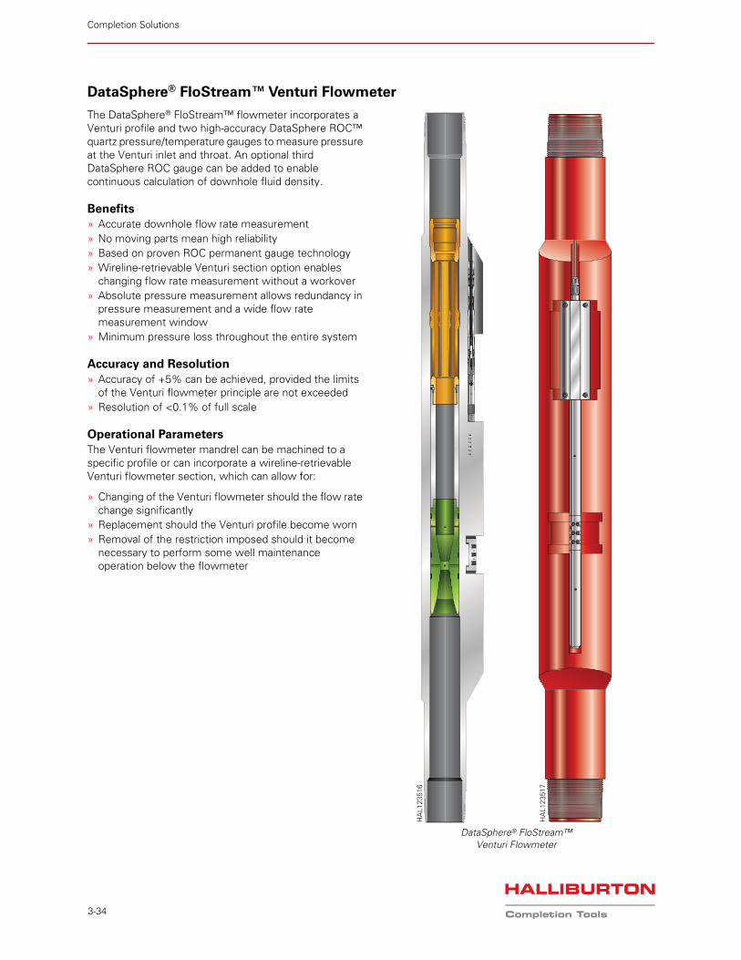
The DataSphere® FloStream™ flowmeter incorporates a Venturi profile and two high-accuracy DataSphere ROC™ quartz pressure/temperature gauges to measure pressure at the Venturi inlet and throat. An optional third DataSphere ROC gauge can be added to enable continuous calculation of downhole fluid density.
Benefits» Accurate downhole flow rate measurement» No moving parts mean high reliability» Based on proven ROC permanent gauge technology» Wireline-retrievable Venturi section option enables
changing flow rate measurement without a workover» Absolute pressure measurement allows redundancy in
pressure measurement and a wide flow rate measurement window
» Minimum pressure loss throughout the entire system
Accuracy and Resolution» Accuracy of +5% can be achieved, provided the limits
of the Venturi flowmeter principle are not exceeded» Resolution of <0.1% of full scale
Operational ParametersThe Venturi flowmeter mandrel can be machined to a specific profile or can incorporate a wireline-retrievable Venturi flowmeter section, which can allow for:
» Changing of the Venturi flowmeter should the flow rate change significantly
» Replacement should the Venturi profile become worn» Removal of the restriction imposed should it become
necessary to perform some well maintenance operation below the flowmeter
DataSphere® FloStream™Venturi Flowmeter
HA
L123
517
HA
L123
516

Completion Solutions | Intelligent Completions
3-35
DataSphere® Array System
The DataSphere® Array system is the next step in the evolution of Halliburton Permanent Monitoring solutions. The technology is built upon the reliability of ROC™ gauge hybrid technology and provides greater system customization by deploying multiple discrete sensors across challenging wellbore regions.
A system comprising conventional gauges can communicate with multiple Array sensor systems distributed across different wellbore intervals. Each Array system provides discrete real-time annular downhole distributed multi-point temperature and pressure monitoring data. The Array system incorporates no cable terminations, which reduces installation time and eliminates risks associated with multiple terminations. Furthermore, the Array system uses internal short circuit protection circuitry that minimizes system line takedowns.
Based on an industry-standard, field-proven resonating quartz crystal sensor, the Array system can be used for distributed, single zone, or multizone monitoring applications. During distributed monitoring, the use of Halliburton conventional downhole gauges can be enhanced by the Array system, allowing operators greater visibility into their operations efficiency in a cost-effective manner.
Applications» Inflow control device (ICD)
efficiency monitoring» Production monitoring» Injection monitoring» Field reservoir monitoring» SmartWell® completion system
optimization» Artificial lift/gas lift optimization
Features» Can be deployed standalone» Up to 50 sensors per array» ROC-Modbus® communication
protocol
» Designed for harsh environments up to 10,000 psi and 150°C
» AWES qualified» Reduced OD design» Multi-drop capability on single core
tubing encased conductor (TEC)» Available as temperature only or
both pressure and temperature» Hermetically sealed electron beam-
welded design» Application Specific Integrated
Chip (ASIC) technology» Increased capabilities, such as fault
protection per sensor» Designed for a 20-year life
Benefits» Quartz sensors provide high
accuracy and resolution and low drift
» Can be deployed across the sandface for greater reservoir inflow/outflow understanding
» Reduces rig time through faster installation times (up to 8 hours saved per gauge)
» Reduces need for cable terminations
» Eliminates requirement for gauge mandrels in annular sensing applications
» Validates/disproves reservoir models
» Tool head voltage and gauge current measurement for diagnostics
» Reduces potential leak points by minimizing system connections
FMJ Cable TerminationWhen connected to a conventional gauge, the DataSphere Array system uses a high-performance cable termination that uses a sealing arrangement based on the highly reliable, field-proven, intelligent completion FMJ connector. This cable termination incorporates a pressure-testable dual metal-to-metal ferrule seal arrangement for isolating the downhole cable outer metal sheath from the well fluid.
DataSphere® Array System
HA
L123
507
Completion Solutions
3-36
TestingThe individual sensor design has gone through the Design for Reliability process, which includes a Highly Accelerated Lifetime Test (HALT) program. This program is a series of controlled environmental stresses designed to ensure that stringent criteria are met for thermal shock, mechanical shock, vibration, and thermal aging. During manufacture, all gauges are also subjected to Environmental Stress Screening (ESS) to highlight any defect in functionality before installation at the well site. This screening method has proven to be far more effective than “burn-in” techniques.
All of the individual sensors that compose the DataSphere® Array system are independently calibration checked in our manufacturing facility. During Factory Acceptance Testing (FAT), the DataSphere Array sensor welds are pressure tested for integrity as the array is being built and spooled onto the final drum.
DataSphere Array System Designs» Quartz transducer and hybrid technology» ASIC technology» Maximum 150°C operating temperature» Multi-drop capability to 10,000-ft maximum depth» Can be used in conjunction with existing gauges» Improved shock and vibration performance» 0.625-in. OD ultra-slim design» Less than 7-in. length per sensor» Does not need a gauge mandrel to be deployed» Short-circuit protection per sensor, prevents line
takedowns
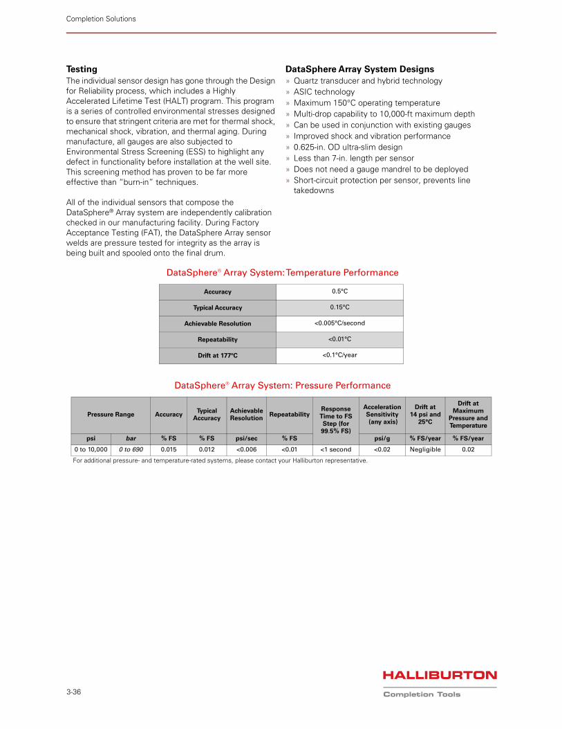
DataSphere® Array System: Temperature Performance
Accuracy 0.5°C
Typical Accuracy 0.15°C
Achievable Resolution <0.005°C/second
Repeatability <0.01°C
Drift at 177ºC <0.1°C/year
DataSphere® Array System: Pressure Performance
Pressure Range Accuracy Typical
AccuracyAchievable Resolution
Repeatability Response Time to FS Step (for 99.5% FS)
Acceleration Sensitivity (any axis)
Drift at 14 psi and
25°C
Drift at Maximum
Pressure and Temperature
psi bar % FS % FS psi/sec % FS psi/g % FS/year % FS/year
0 to 10,000 0 to 690 0.015 0.012 <0.006 <0.01 <1 second <0.02 Negligible 0.02
For additional pressure- and temperature-rated systems, please contact your Halliburton representative.
Completion Solutions | Intelligent Completions
3-37
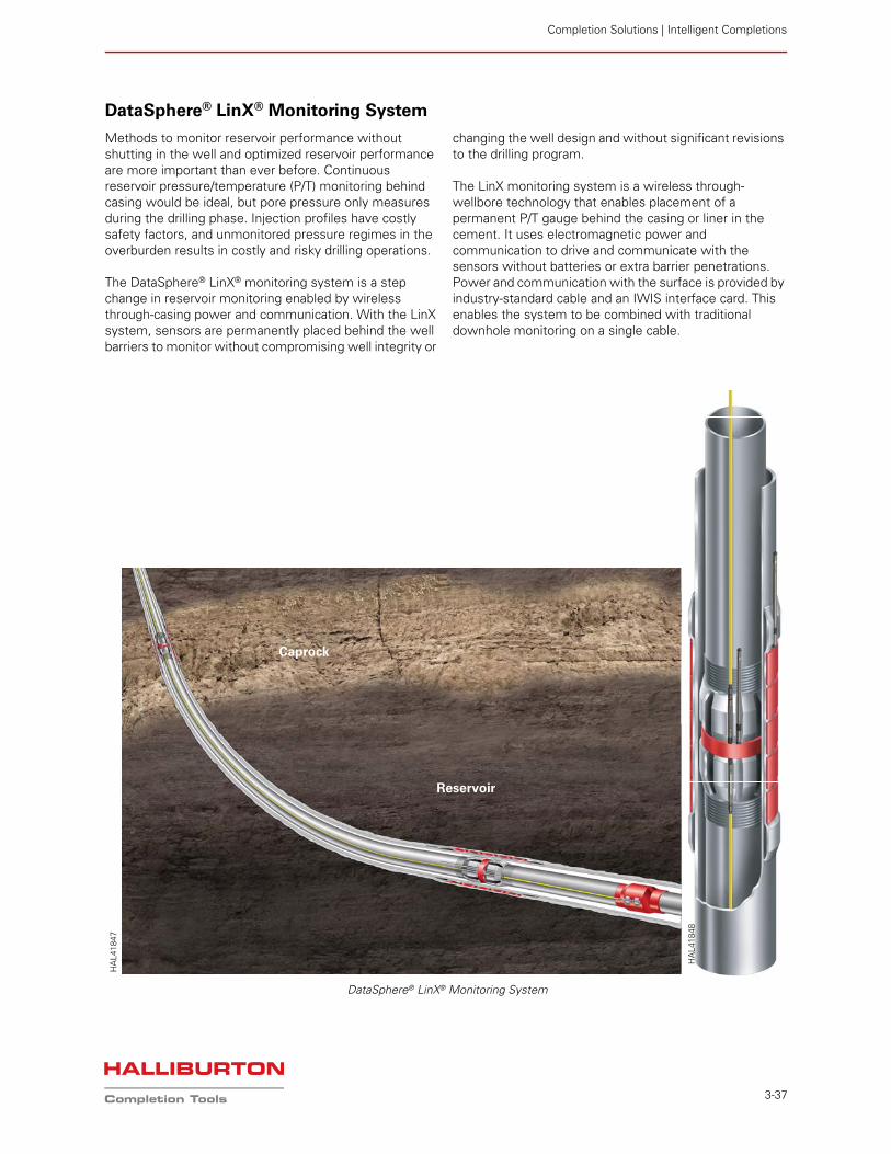
DataSphere® LinX® Monitoring System
Methods to monitor reservoir performance without shutting in the well and optimized reservoir performance are more important than ever before. Continuous reservoir pressure/temperature (P/T) monitoring behind casing would be ideal, but pore pressure only measures during the drilling phase. Injection profiles have costly safety factors, and unmonitored pressure regimes in the overburden results in costly and risky drilling operations.
The DataSphere® LinX® monitoring system is a step change in reservoir monitoring enabled by wireless through-casing power and communication. With the LinX system, sensors are permanently placed behind the well barriers to monitor without compromising well integrity or
changing the well design and without significant revisions to the drilling program.
The LinX monitoring system is a wireless through-wellbore technology that enables placement of a permanent P/T gauge behind the casing or liner in the cement. It uses electromagnetic power and communication to drive and communicate with the sensors without batteries or extra barrier penetrations. Power and communication with the surface is provided by industry-standard cable and an IWIS interface card. This enables the system to be combined with traditional downhole monitoring on a single cable.
Caprock
Reservoir
HA
L418
48
DataSphere® LinX® Monitoring System
HA
L418
47
Completion Solutions
3-38
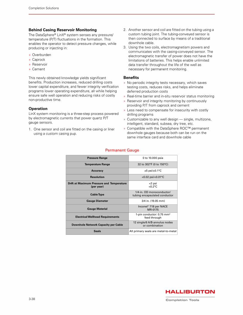
Behind Casing Reservoir MonitoringThe DataSphere® LinX® system senses any pressure/temperature (P/T) fluctuations in the formation. This enables the operator to detect pressure changes, while producing or injecting in:
» Overburden» Caprock» Reservoir» Cement
This newly obtained knowledge yields significant benefits. Production increases, reduced drilling costs lower capital expenditure, and fewer integrity verification programs lower operating expenditure, all while helping ensure safe well operation and reducing risks of costly non-productive time.
OperationLinX system monitoring is a three-step process powered by electromagnetic currents that power quartz P/T gauge sensors.
1. One sensor and coil are fitted on the casing or liner using a custom casing pup.
2. Another sensor and coil are fitted on the tubing using a custom tubing joint. The tubing-conveyed sensor is then connected to surface by means of a traditional downhole cable.
3. Using the two coils, electromagnetism powers and communicates with the casing-conveyed sensor. The electromagnetic transfer of power does not have the limitations of batteries. This helps enable unlimited data transfer throughout the life of the well as necessary for permanent monitoring.
Benefits» No periodic integrity tests necessary, which saves
testing costs, reduces risks, and helps eliminate deferred production costs
» Real-time barrier and in-situ reservoir status monitoring» Reservoir and integrity monitoring by continuously
providing P/T from caprock and cement» Less need to compensate for insecurity with costly
drilling programs» Customizable to any well design — single, multizone,
intelligent, standard, subsea, dry tree, etc.» Compatible with the DataSphere ROC™ permanent
downhole gauges because both can be run on the same interface card and downhole cable
Permanent Gauge
Pressure Range 0 to 10.000 psia
Temperature Range 32 to 302°F (0 to 150°C)
Accuracy ±5 psi/±0.1°C
Resolution <0.02 psi/<0.01°C
Drift at Maximum Pressure and Temperature (per year)
<2 psi<0.2°C
Cable Type1/4-in. OD monoconductor/
tubing encapsulated conductor
Gauge Diameter 3/4 in. (19.05 mm)
Gauge MaterialInconel® 718 per NACE
MR-0175
Electrical Wellhead Requirements1-pin conductor: 0.75 mm²
feed through
Downhole Network Capacity per Cable12 single/6 A/B-annulus nodes
or combination
Seals All primary seals are metal-to-metal
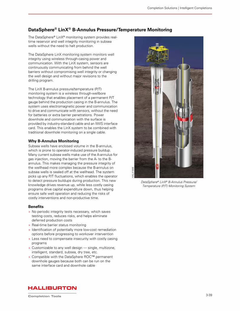
Completion Solutions | Intelligent Completions
3-39
DataSphere® LinX® B-Annulus Pressure/Temperature Monitoring
The DataSphere® LinX® monitoring system provides real-time reservoir and well integrity monitoring in subsea wells without the need to halt production.
The DataSphere LinX monitoring system monitors well integrity using wireless through-casing power and communication. With the LinX system, sensors are continuously communicating from behind the well barriers without compromising well integrity or changing the well design and without major revisions to the drilling program.
The LinX B-annulus pressure/temperature (P/T) monitoring system is a wireless through-wellbore technology that enables placement of a permanent P/T gauge behind the production casing in the B-annulus. The system uses electromagnetic power and communication to drive and communicate with sensors, without the need for batteries or extra barrier penetrations. Power downhole and communication with the surface is provided by industry-standard cable and an IWIS interface card. This enables the LinX system to be combined with traditional downhole monitoring on a single cable.
Why B-Annulus MonitoringSubsea wells have enclosed volume in the B-annulus, which is prone to operator-induced pressure buildup. Many current subsea wells make use of the A-annulus for gas injection, moving the barrier from the A- to the B-annulus. This makes managing the pressure integrity of the wellhead more complex because the B-annulus on subsea wells is sealed off at the wellhead. The system picks up any P/T fluctuations, which enables the operator to detect pressure buildups during production. This new knowledge drives revenue up, while less costly casing programs drive capital expenditure down, thus helping ensure safe well operation and reducing the risks of costly interventions and non-productive time.
Benefits» No periodic integrity tests necessary, which saves
testing costs, reduces risks, and helps eliminate deferred production costs
» Real-time barrier status monitoring» Identification of potentially more low-cost remediation
options before progressing to workover intervention» Less need to compensate insecurity with costly casing
programs» Customizable to any well design — single, multizone,
intelligent, standard, subsea, dry tree, etc.» Compatible with the DataSphere ROC™ permanent
downhole gauges because both can be run on the same interface card and downhole cable
DataSphere® LinX® B-Annulus Pressure/Temperature (P/T) Monitoring System
HA
L418
46
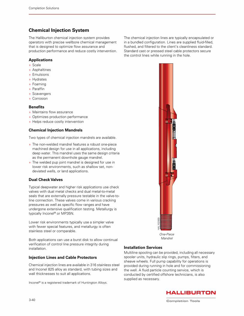
Completion Solutions
3-40
Chemical Injection System
The Halliburton chemical injection system provides operators with precise wellbore chemical management that is designed to optimize flow assurance and production performance and reduce costly intervention.
Applications» Scale» Asphaltines» Emulsions» Hydrates» Foaming» Paraffin» Scavengers» Corrosion
Benefits» Maintains flow assurance» Optimizes production performance» Helps reduce costly intervention
Chemical Injection Mandrels
Two types of chemical injection mandrels are available.
» The non-welded mandrel features a robust one-piece machined design for use in all applications, including deep water. This mandrel uses the same design criteria as the permanent downhole gauge mandrel.
» The welded pup joint mandrel is designed for use in lower risk environments, such as shallow set, non-deviated wells, or land applications.
Dual Check Valves
Typical deepwater and higher risk applications use check valves with dual metal checks and dual metal-to-metal seals that are externally pressure testable in the valve-to-line connection. These valves come in various cracking pressures as well as specific flow ranges and have undergone extensive qualification testing. Metallurgy is typically Inconel® or MP35N.
Lower risk environments typically use a simpler valve with fewer special features, and metallurgy is often stainless steel or comparable.
Both applications can use a burst disk to allow continual verification of control line pressure integrity during installation.
Injection Lines and Cable Protectors
Chemical injection lines are available in 316 stainless steel and Inconel 825 alloy as standard, with tubing sizes and wall thicknesses to suit all applications.
Inconel® is a registered trademark of Huntington Alloys.
The chemical injection lines are typically encapsulated or in a bundled configuration. Lines are supplied fluid-filled, flushed, and filtered to the client’s cleanliness standard. Standard cast or pressed steel cable protectors secure the control lines while running in the hole.
Installation ServicesMultiline spooling can be provided, including all necessary spooler units, hydraulic slip rings, pumps, filters, and sheave wheels. Full pump capability for operations is provided during running in hole and for commissioning the well. A fluid particle counting service, which is conducted by certified offshore technicians, is also supplied as necessary.
One-Piece Mandrel
HA
L102
069
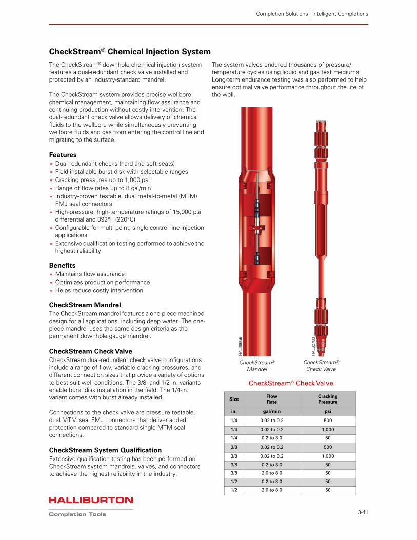
Completion Solutions | Intelligent Completions
3-41
CheckStream® Chemical Injection System
The CheckStream® downhole chemical injection system features a dual-redundant check valve installed and protected by an industry-standard mandrel.
The CheckStream system provides precise wellbore chemical management, maintaining flow assurance and continuing production without costly intervention. The dual-redundant check valve allows delivery of chemical fluids to the wellbore while simultaneously preventing wellbore fluids and gas from entering the control line and migrating to the surface.
Features» Dual-redundant checks (hard and soft seats)» Field-installable burst disk with selectable ranges» Cracking pressures up to 1,000 psi» Range of flow rates up to 8 gal/min» Industry-proven testable, dual metal-to-metal (MTM)
FMJ seal connectors» High-pressure, high-temperature ratings of 15,000 psi
differential and 392°F (220°C)» Configurable for multi-point, single control-line injection
applications» Extensive qualification testing performed to achieve the
highest reliability
Benefits» Maintains flow assurance» Optimizes production performance» Helps reduce costly intervention
CheckStream MandrelThe CheckStream mandrel features a one-piece machined design for all applications, including deep water. The one-piece mandrel uses the same design criteria as the permanent downhole gauge mandrel.
CheckStream Check ValveCheckStream dual-redundant check valve configurations include a range of flow, variable cracking pressures, and different connection sizes that provide a variety of options to best suit well conditions. The 3/8- and 1/2-in. variants enable burst disk installation in the field. The 1/4-in. variant comes with burst already installed.
Connections to the check valve are pressure testable, dual MTM seal FMJ connectors that deliver added protection compared to standard single MTM seal connections.
CheckStream System QualificationExtensive qualification testing has been performed on CheckStream system mandrels, valves, and connectors to achieve the highest reliability in the industry.
The system valves endured thousands of pressure/temperature cycles using liquid and gas test mediums. Long-term endurance testing was also performed to help ensure optimal valve performance throughout the life of the well.
CheckStream® Check Valve
Size Flow Rate
Cracking Pressure
in. gal/min psi
1/4 0.02 to 0.2 500
1/4 0.02 to 0.2 1,000
1/4 0.2 to 3.0 50
3/8 0.02 to 0.2 500
3/8 0.02 to 0.2 1,000
3/8 0.2 to 3.0 50
3/8 2.0 to 8.0 50
1/2 0.2 to 3.0 50
1/2 2.0 to 8.0 50
CheckStream® Check Valve
CheckStream® Mandrel
HA
L827
83
HA
L386
55
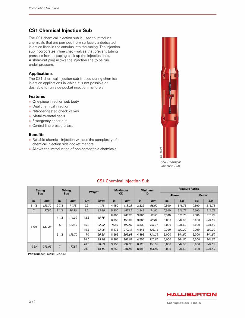
Completion Solutions
3-42
CS1 Chemical Injection Sub
The CS1 chemical injection sub is used to introduce chemicals that are pumped from surface via dedicated injection lines in the annulus into the tubing. The injection sub incorporates inline check valves that prevent tubing pressure from escaping back up the injection lines. A shear-out plug allows the injection line to be run under pressure.
ApplicationsThe CS1 chemical injection sub is used during chemical injection applications in which it is not possible or desirable to run side-pocket injection mandrels.
Features» One-piece injection sub body» Dual chemical injection» Nitrogen-tested check valves» Metal-to-metal seals» Emergency shear-out» Control-line pressure test
Benefits» Reliable chemical injection without the complexity of a
chemical injection side-pocket mandrel» Allows the introduction of non-compatible chemicals
CS1 Chemical Injection Sub
HA
L386
55
CS1 Chemical Injection Sub
Casing Size
TubingSize
WeightMaximum
ODMinimum
ID
Pressure Rating
Above Below
in. mm in. mm lb/ft kg/m in. mm in. mm psi bar psi bar
5 1/2 139.70 2 7/8 71.75 7.9 11.76 4.450 113.03 2.229 56.62 7,500 516.75 7,500 516.75
7 177.80 3 1/2 88.90 9.2 13.69 5.800 147.32 2.949 74.90 7,500 516.75 7,500 516.75
9 5/8 244.48
4 1/2 114.30 12.6 18.758.000 203.20 3.880 98.55 7,500 516.75 7,500 516.75
6.050 153.67 3.860 98.04 5,000 344.50 5,000 344.50
5 127.00 15.0 22.32 7.515 190.88 4.339 110.21 5,000 344.50 5,000 344.50
5 1/2 139.70
15.5 23.06 8.275 210.19 4.848 123.14 7,000 482.30 7,000 482.30
17.0 25.28 8.265 209.93 4.892 124.26 5,000 344.50 5,000 344.50
20.0 29.76 8.265 209.93 4.756 120.80 5,000 344.50 5,000 344.50
10 3/4 273.05 7 177.8026.0 38.69 9.250 234.95 6.125 155.58 5,000 344.50 5,000 344.50
29.0 43.15 9.250 234.95 6.098 154.89 5,000 344.50 5,000 344.50
Part Number Prefix: P.220CS1
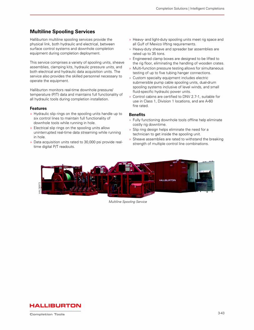
Completion Solutions | Intelligent Completions
3-43
Multiline Spooling Services
Halliburton multiline spooling services provide the physical link, both hydraulic and electrical, between surface control systems and downhole completion equipment during completion deployment.
This service comprises a variety of spooling units, sheave assemblies, clamping kits, hydraulic pressure units, and both electrical and hydraulic data acquisition units. The service also provides the skilled personnel necessary to operate the equipment.
Halliburton monitors real-time downhole pressure/ temperature (P/T) data and maintains full functionality of all hydraulic tools during completion installation.
Features» Hydraulic slip rings on the spooling units handle up to
six control lines to maintain full functionality of downhole tools while running in hole.
» Electrical slip rings on the spooling units allow uninterrupted real-time data streaming while running in hole.
» Data acquisition units rated to 30,000 psi provide real-time digital P/T readouts.
» Heavy- and light-duty spooling units meet rig space and all Gulf of Mexico lifting requirements.
» Heavy-duty sheave and spreader bar assemblies are rated up to 35 tons.
» Engineered clamp boxes are designed to be lifted to the rig floor, eliminating the handling of wooden crates.
» Multi-function pressure testing allows for simultaneous testing of up to five tubing hanger connections.
» Custom specialty equipment includes electric submersible pump cable spooling units, dual-drum spooling systems inclusive of level winds, and small fluid-specific hydraulic power units.
» Control cabins are certified to DNV 2.7-1, suitable for use in Class 1, Division 1 locations, and are A-60 fire rated.
Benefits» Fully functioning downhole tools offline help eliminate
costly rig downtime.» Slip ring design helps eliminate the need for a
technician to get inside the spooling unit.» Sheave assemblies are rated to withstand the breaking
strength of multiple control line combinations.
Multiline Spooling Service
HA
L369
73
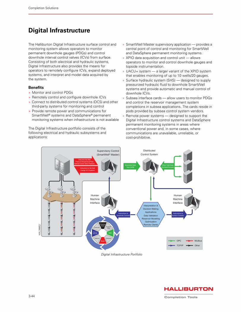
Completion Solutions
3-44
Digital Infrastructure
The Halliburton Digital Infrastructure surface control and monitoring system allows operators to monitor permanent downhole gauges (PDGs) and control downhole interval control valves (ICVs) from surface. Consisting of both electrical and hydraulic systems, Digital Infrastructure also provides the means for operators to remotely configure ICVs, expand deployed systems, and interpret and model data acquired by the system.
Benefits» Monitor and control PDGs» Remotely control and configure downhole ICVs» Connect to distributed control systems (DCS) and other
third-party systems for monitoring and control» Provide remote power and communications for
SmartWell® systems and DataSphere® permanent monitoring systems when infrastructure is not available
The Digital Infrastructure portfolio consists of the following electrical and hydraulic subsystems and applications:
» SmartWell Master supervisory application — provides a central point of control and monitoring for SmartWell and DataSphere permanent monitoring systems.
» XPIO data acquisition and control unit — allows operators to monitor and control downhole gauges and topside instrumentation.
» UACU+ system — a larger variant of the XPIO system that enables monitoring of up to 10 wells/20 gauges.
» Surface hydraulic system (SHS) — designed to supply pressurized hydraulic fluid to downhole SmartWell systems and provide automatic and manual control of downhole ICVs.
» Subsea interface cards — allow users to monitor PDGs and control the reservoir management system completions in subsea applications. The cards reside in pods provided by subsea control system vendors.
» Remote power systems — designed to support the Digital Infrastructure control systems and DataSphere permanent monitoring systems in areas where conventional power and, in some cases, where communications are unavailable, unreliable, or cost-prohibitive.
Data from the WellPressure/Temperature/Flow
Interval Control Valve Positions
Instructions to the WellChange ICV Positions
Supervisory Control(SmartWell® Master)
HumanMachineInterface
HumanMachineInterface
OPC
DistributedControl System
Instructions toDownhole Controls
Other Field Data(Surface/Process)
Instructions toSurface Controls
Downhole Datafrom SWM
Interpretation &Decision Making
Applications
Data ValidationReservoir Modeling
OptimizationRemote Clients
TCP/IP
Modbus
Other
AcquireData
Interpret
Data
Execute
Options
Plan &Decide
Model
PhysicalAsset
Digital Infrastructure Portfolio
HA
L398
52
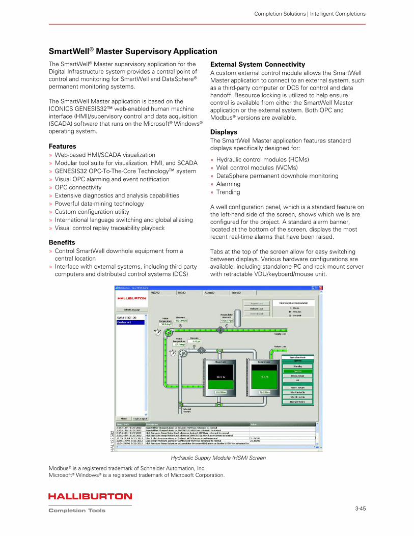
Completion Solutions | Intelligent Completions
3-45
SmartWell® Master Supervisory Application
The SmartWell® Master supervisory application for the Digital Infrastructure system provides a central point of control and monitoring for SmartWell and DataSphere® permanent monitoring systems.
The SmartWell Master application is based on the ICONICS GENESIS32™ web-enabled human machine interface (HMI)/supervisory control and data acquisition (SCADA) software that runs on the Microsoft® Windows® operating system.
Features» Web-based HMI/SCADA visualization» Modular tool suite for visualization, HMI, and SCADA» GENESIS32 OPC-To-The-Core Technology™ system» Visual OPC alarming and event notification» OPC connectivity» Extensive diagnostics and analysis capabilities» Powerful data-mining technology» Custom configuration utility» International language switching and global aliasing» Visual control replay traceability playback
Benefits» Control SmartWell downhole equipment from a
central location» Interface with external systems, including third-party
computers and distributed control systems (DCS)
External System ConnectivityA custom external control module allows the SmartWell Master application to connect to an external system, such as a third-party computer or DCS for control and data handoff. Resource locking is utilized to help ensure control is available from either the SmartWell Master application or the external system. Both OPC and Modbus® versions are available.
DisplaysThe SmartWell Master application features standard displays specifically designed for:
» Hydraulic control modules (HCMs)» Well control modules (WCMs)» DataSphere permanent downhole monitoring» Alarming» Trending
A well configuration panel, which is a standard feature on the left-hand side of the screen, shows which wells are configured for the project. A standard alarm banner, located at the bottom of the screen, displays the most recent real-time alarms that have been raised.
Tabs at the top of the screen allow for easy switching between displays. Various hardware configurations are available, including standalone PC and rack-mount server with retractable VDU/keyboard/mouse unit.
Modbus® is a registered trademark of Schneider Automation, Inc.Microsoft® Windows® is a registered trademark of Microsoft Corporation.
Hydraulic Supply Module (HSM) Screen
HA
L122
582
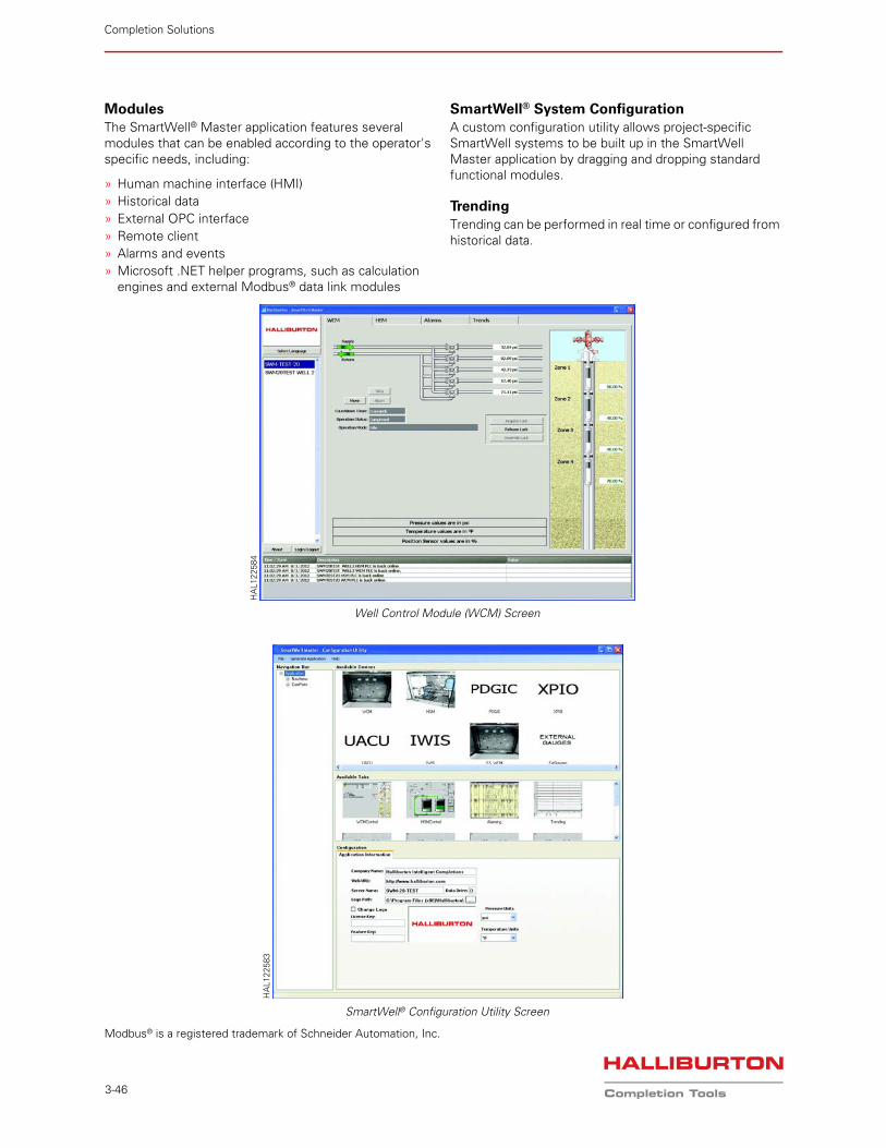
Completion Solutions
3-46
ModulesThe SmartWell® Master application features several modules that can be enabled according to the operator's specific needs, including:
» Human machine interface (HMI)» Historical data» External OPC interface» Remote client» Alarms and events» Microsoft .NET helper programs, such as calculation
engines and external Modbus® data link modules
SmartWell® System ConfigurationA custom configuration utility allows project-specific SmartWell systems to be built up in the SmartWell Master application by dragging and dropping standard functional modules.
TrendingTrending can be performed in real time or configured from historical data.
Modbus® is a registered trademark of Schneider Automation, Inc.
Well Control Module (WCM) Screen
HA
L122
584
SmartWell® Configuration Utility Screen
HA
L122
583
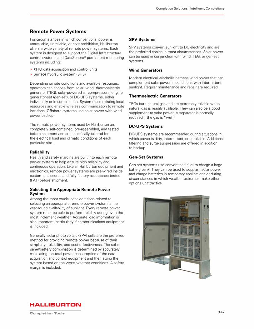
Completion Solutions | Intelligent Completions
3-47
Remote Power Systems
For circumstances in which conventional power is unavailable, unreliable, or cost-prohibitive, Halliburton offers a wide variety of remote power systems. Each system is designed to support the Digital Infrastructure control systems and DataSphere® permanent monitoring systems including:
» XPIO data acquisition and control units» Surface hydraulic system (SHS)
Depending on site conditions and available resources, operators can choose from solar, wind, thermoelectric generator (TEG), solar-powered air compressors, engine generator-set (gen-set), or DC-UPS systems, either individually or in combination. Systems use existing local resources and enable wireless communication to remote locations. Offshore systems use solar power with wind power backup.
The remote power systems used by Halliburton are completely self-contained, pre-assembled, and tested before shipment and are specifically tailored for the electrical load and climatic conditions of each particular site.
ReliabilityHealth and safety margins are built into each remote power system to help ensure high reliability and continuous operation. Like all Halliburton equipment and electronics, remote power systems are pre-wired inside custom enclosures and fully factory-acceptance tested (FAT) before shipment.
Selecting the Appropriate Remote Power SystemAmong the most crucial considerations related to selecting an appropriate remote power system is the year-round availability of sunlight. Every remote power system must be able to perform reliably during even the most inclement weather. Accurate load information is also important, particularly if communications equipment is included.
Generally, solar photo voltaic (SPV) cells are the preferred method for providing remote power because of their simplicity, reliability, and cost-effectiveness. The solar panel/battery combination is determined by accurately calculating the total power consumption of the data acquisition and control equipment and then sizing the system based on the worst weather conditions. A safety margin is included.
SPV Systems
SPV systems convert sunlight to DC electricity and are the preferred choice in most circumstances. Solar power can be used in conjunction with wind, TEG, or gen-set systems.
Wind Generators
Modern electrical windmills harness wind power that can complement solar power in conditions with intermittent sunlight. Regular maintenance and repair are required.
Thermoelectric Generators
TEGs burn natural gas and are extremely reliable when natural gas is readily available. They can also be a good supplement to solar power. A separator is normally required if the gas is “wet.”
DC-UPS Systems
DC-UPS systems are recommended during situations in which power is dirty, intermittent, or unreliable. Additional filtering and surge suppression are offered in addition to backup.
Gen-Set Systems
Gen-set systems use conventional fuel to charge a large battery bank. They can be used to supplant solar power and charge batteries in temporary applications or during circumstances in which weather extremes make other options unattractive.
Completion Solutions
3-48
XPIO Data Acquisition and Control Unit
The Halliburton XPIO data acquisition and control system allows operators to monitor and control downhole gauges and topside instrumentation. Acquiring data at a rate of 0.5 seconds per gauge, the XPIO system is available in a range of capacities, from one well/four gauges to four wells/eight gauges. A larger variant within the XPIO range is the UACU+, which extends capacity up to 10 wells/20 gauges for a single unit. The UACU+ is fitted with a permanent downhole gauge interface card (PDGIC) module for each downhole channel.
Downhole cable inputs are independent and fully isolated.
Features» Up to four permanent downhole gauge (PDG)
communications channels (up to 10 for UACU+)» Five channels of 4-20 mA analog inputs (12 bit)» Four channels of 4-20 mA analog outputs (16 bit)» 8-MB onboard flash memory plus 4 GB of
CompactFlash memory» Modbus® RTU protocol support via the RS-485 or
RS-232 port or via the TCP/IP port» Modem communications support via the RS-232 port» Two relay contacts» Communications programs that allow full configuration
of the unit
Benefits» Control PDGs, including the DataSphere® ROC™ and
SmartLog™ gauges and surface instruments» Store and display data from Halliburton PDGs and
surface sensors» Interface with external systems, including third-party
computers and distributed control systems (DCS)
Analog InputsThe XPIO system features five channels of 4-20 mA inputs (12 bit) that are fully configurable using the XPIO 2K PC program. Users can set the offset, span, and units of measure and then can choose to monitor them on the display or log them into memory.
Analog OutputsThe XPIO system features four channels of 4-20 mA outputs (16 bit). Users can select the pressure, temperature, span, and offset of a PDG, and the XPIO system will drive the translated value onto an output as it is decoded from downhole.
Memory LoggingThe XPIO system includes 8 MB of onboard flash memory. A CompactFlash card extends the memory by 4 GB as standard.
The standard 4-GB CompactFlash provides memory capacity to hold pressure and temperature data from two gauges at 1-second updates for more than 1 year.
The data are retrieved via an RS-232 port using the supplied PC program or by file transfer protocol (FTP) over the TCP/IP link and can easily be imported to other applications, such as a spreadsheet. Data are logged to memory at a maximum rate of once per second.
Both the standard XPIO and UACU+ are available in NEMA 4X enclosure and 19-in. rack-mount versions. The 19-in. rack-mount UACU+ has a capacity of 10 wells/20 gauges.
Serial CommunicationsThe XPIO system supports Modbus RTU protocol via its RS-485 or RS-232 port or via its TCP/IP port. These interfaces are fully configurable in terms of parity, baud rate, etc. As a slave device, the XPIO system provides gauge data (i.e., pressure and temperature) that can be polled as well as data from any of the 4-20 mA inputs. Time and date are also available.
Modem SupportThe XPIO system supports modem communications via the RS-232 port. Users can dial into the unit using the supplied XPIO 2K PC program or use the port to talk to Modbus over a radio modem, cellular modem, or regular modem.
Pressure-Controlled Relay ContactsThe XPIO system includes two relay contacts (1/2 A at 115 VAC), which are controlled by software. When a selected gauge's pressure rises above or falls below a set pressure, the contact is closed. This feature is ideal for alarms and/or pump control.
Web-Installed PC ApplicationThe XPIO system includes a web-installed application that provides for full configuration of the unit as well as data memory retrieval, real-time logging of data to the computer hard drive, and real-time data trending.
The application communicates with the XPIO system via a standard RS-232 port and runs under Microsoft®
Windows® 2000/XP/Vista/Win10.
Modbus® is a registered trademark of Schneider Automation, Inc.
Microsoft® Windows® is a registered trademark of Microsoft Corporation.
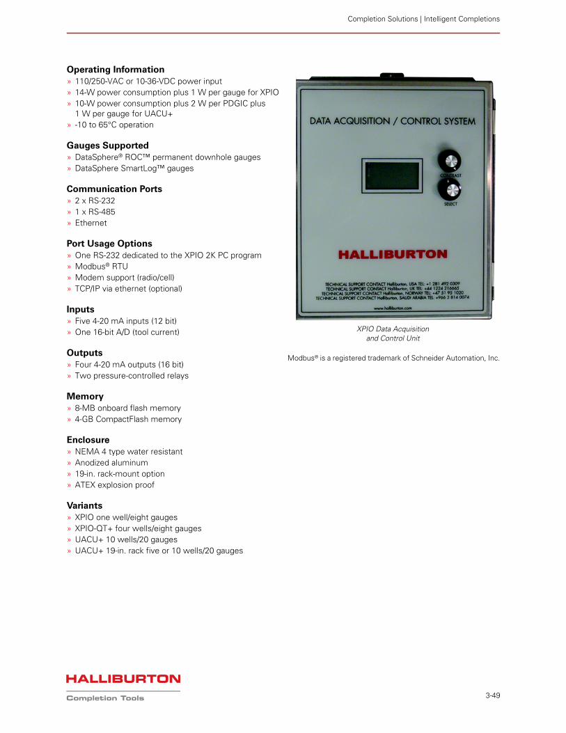
Completion Solutions | Intelligent Completions
3-49
Operating Information» 110/250-VAC or 10-36-VDC power input» 14-W power consumption plus 1 W per gauge for XPIO» 10-W power consumption plus 2 W per PDGIC plus
1 W per gauge for UACU+» -10 to 65°C operation
Gauges Supported» DataSphere® ROC™ permanent downhole gauges» DataSphere SmartLog™ gauges
Communication Ports» 2 x RS-232» 1 x RS-485» Ethernet
Port Usage Options» One RS-232 dedicated to the XPIO 2K PC program» Modbus® RTU» Modem support (radio/cell)» TCP/IP via ethernet (optional)
Inputs» Five 4-20 mA inputs (12 bit)» One 16-bit A/D (tool current)
Outputs» Four 4-20 mA outputs (16 bit)» Two pressure-controlled relays
Memory» 8-MB onboard flash memory» 4-GB CompactFlash memory
Enclosure» NEMA 4 type water resistant» Anodized aluminum» 19-in. rack-mount option» ATEX explosion proof
Variants» XPIO one well/eight gauges» XPIO-QT+ four wells/eight gauges» UACU+ 10 wells/20 gauges» UACU+ 19-in. rack five or 10 wells/20 gauges
Modbus® is a registered trademark of Schneider Automation, Inc.
XPIO Data Acquisition and Control Unit
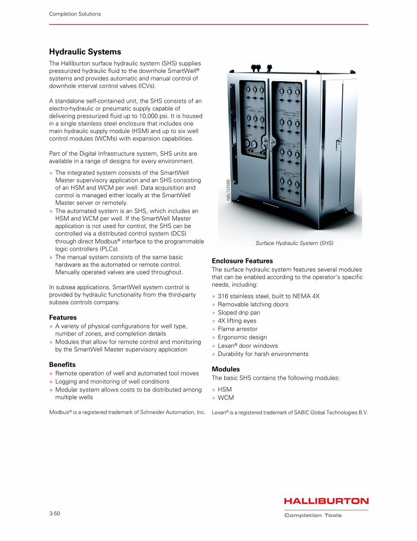
Completion Solutions
3-50
Hydraulic Systems
The Halliburton surface hydraulic system (SHS) supplies pressurized hydraulic fluid to the downhole SmartWell® systems and provides automatic and manual control of downhole interval control valves (ICVs).
A standalone self-contained unit, the SHS consists of an electro-hydraulic or pneumatic supply capable of delivering pressurized fluid up to 10,000 psi. It is housed in a single stainless steel enclosure that includes one main hydraulic supply module (HSM) and up to six well control modules (WCMs) with expansion capabilities.
Part of the Digital Infrastructure system, SHS units are available in a range of designs for every environment.
» The integrated system consists of the SmartWell Master supervisory application and an SHS consisting of an HSM and WCM per well. Data acquisition and control is managed either locally at the SmartWell Master server or remotely.
» The automated system is an SHS, which includes an HSM and WCM per well. If the SmartWell Master application is not used for control, the SHS can be controlled via a distributed control system (DCS) through direct Modbus® interface to the programmable logic controllers (PLCs).
» The manual system consists of the same basic hardware as the automated or remote control. Manually operated valves are used throughout.
In subsea applications, SmartWell system control is provided by hydraulic functionality from the third-party subsea controls company.
Features» A variety of physical configurations for well type,
number of zones, and completion details» Modules that allow for remote control and monitoring
by the SmartWell Master supervisory application
Benefits» Remote operation of well and automated tool moves» Logging and monitoring of well conditions» Modular system allows costs to be distributed among
multiple wells
Modbus® is a registered trademark of Schneider Automation, Inc.
Enclosure FeaturesThe surface hydraulic system features several modules that can be enabled according to the operator’s specific needs, including:
» 316 stainless steel, built to NEMA 4X» Removable latching doors» Sloped drip pan» 4X lifting eyes» Flame arrestor» Ergonomic design» Lexan® door windows» Durability for harsh environments
ModulesThe basic SHS contains the following modules:
» HSM» WCM
Lexan® is a registered trademark of SABIC Global Technologies B.V.
Surface Hydraulic System (SHS)
HA
L122
588
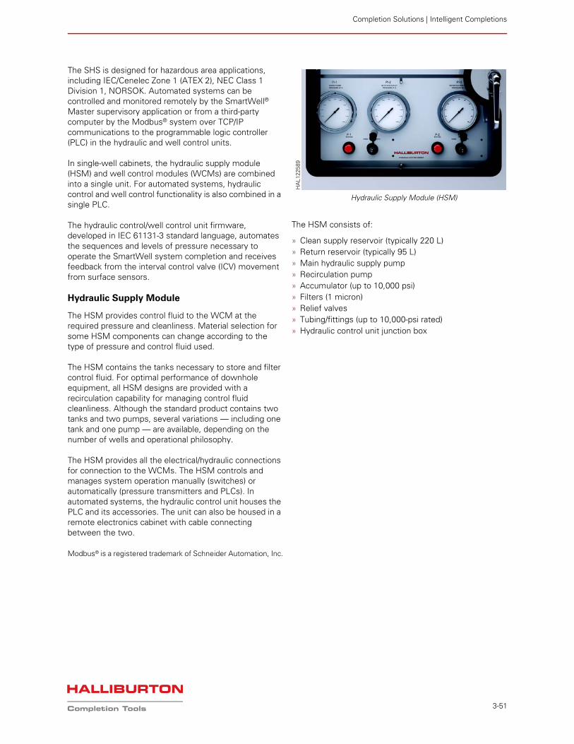
Completion Solutions | Intelligent Completions
3-51
The SHS is designed for hazardous area applications, including IEC/Cenelec Zone 1 (ATEX 2), NEC Class 1 Division 1, NORSOK. Automated systems can be controlled and monitored remotely by the SmartWell® Master supervisory application or from a third-party computer by the Modbus® system over TCP/IP communications to the programmable logic controller (PLC) in the hydraulic and well control units.
In single-well cabinets, the hydraulic supply module (HSM) and well control modules (WCMs) are combined into a single unit. For automated systems, hydraulic control and well control functionality is also combined in a single PLC.
The hydraulic control/well control unit firmware, developed in IEC 61131-3 standard language, automates the sequences and levels of pressure necessary to operate the SmartWell system completion and receives feedback from the interval control valve (ICV) movement from surface sensors.
Hydraulic Supply Module
The HSM provides control fluid to the WCM at the required pressure and cleanliness. Material selection for some HSM components can change according to the type of pressure and control fluid used.
The HSM contains the tanks necessary to store and filter control fluid. For optimal performance of downhole equipment, all HSM designs are provided with a recirculation capability for managing control fluid cleanliness. Although the standard product contains two tanks and two pumps, several variations — including one tank and one pump — are available, depending on the number of wells and operational philosophy.
The HSM provides all the electrical/hydraulic connections for connection to the WCMs. The HSM controls and manages system operation manually (switches) or automatically (pressure transmitters and PLCs). In automated systems, the hydraulic control unit houses the PLC and its accessories. The unit can also be housed in a remote electronics cabinet with cable connecting between the two.
Modbus® is a registered trademark of Schneider Automation, Inc.
The HSM consists of:
» Clean supply reservoir (typically 220 L)» Return reservoir (typically 95 L)» Main hydraulic supply pump» Recirculation pump» Accumulator (up to 10,000 psi)» Filters (1 micron)» Relief valves» Tubing/fittings (up to 10,000-psi rated)» Hydraulic control unit junction box
Hydraulic Supply Module (HSM)
HA
L122
589
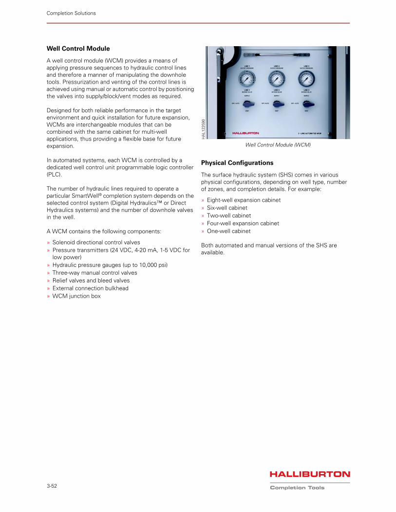
Completion Solutions
3-52
Well Control Module
A well control module (WCM) provides a means of applying pressure sequences to hydraulic control lines and therefore a manner of manipulating the downhole tools. Pressurization and venting of the control lines is achieved using manual or automatic control by positioning the valves into supply/block/vent modes as required.
Designed for both reliable performance in the target environment and quick installation for future expansion, WCMs are interchangeable modules that can be combined with the same cabinet for multi-well applications, thus providing a flexible base for future expansion.
In automated systems, each WCM is controlled by a dedicated well control unit programmable logic controller (PLC).
The number of hydraulic lines required to operate a particular SmartWell® completion system depends on the selected control system (Digital Hydraulics™ or Direct Hydraulics systems) and the number of downhole valves in the well.
A WCM contains the following components:
» Solenoid directional control valves» Pressure transmitters (24 VDC, 4-20 mA, 1-5 VDC for
low power)» Hydraulic pressure gauges (up to 10,000 psi)» Three-way manual control valves» Relief valves and bleed valves» External connection bulkhead» WCM junction box
Physical Configurations
The surface hydraulic system (SHS) comes in various physical configurations, depending on well type, number of zones, and completion details. For example:
» Eight-well expansion cabinet» Six-well cabinet» Two-well cabinet» Four-well expansion cabinet» One-well cabinet
Both automated and manual versions of the SHS are available.
Well Control Module (WCM)
HA
L122
590
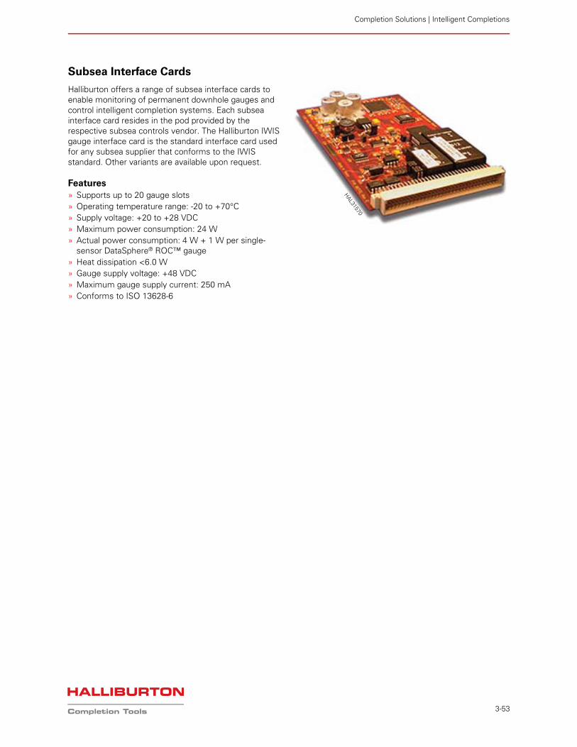
Completion Solutions | Intelligent Completions
3-53
Subsea Interface Cards
Halliburton offers a range of subsea interface cards to enable monitoring of permanent downhole gauges and control intelligent completion systems. Each subsea interface card resides in the pod provided by the respective subsea controls vendor. The Halliburton IWIS gauge interface card is the standard interface card used for any subsea supplier that conforms to the IWIS standard. Other variants are available upon request.
Features» Supports up to 20 gauge slots» Operating temperature range: -20 to +70°C» Supply voltage: +20 to +28 VDC» Maximum power consumption: 24 W» Actual power consumption: 4 W + 1 W per single-
sensor DataSphere® ROC™ gauge» Heat dissipation <6.0 W» Gauge supply voltage: +48 VDC» Maximum gauge supply current: 250 mA» Conforms to ISO 13628-6
HAL31570
Completion Solutions
3-54