Embed Size (px)
Citation preview
Abstract— This paper describes an architecture based upon the IEEE 1451 plug and play distributed smart sensor network standard. The system integration with a commercial of the shelf traffic controller requires a minimum of software modifications. This demonstrates an incremental path to integration of smart signals with conventional traffic signal devices. The system design focused on countdown timers for pedestrian signals because the current designs can give incorrect times when the signal timing changes. The system also demonstrates the ability to provide remote access to the call button to assist visually and mobility impaired pedestrians.
I. INTRODUCTION
ODERN traffic signal controls use highly capable microprocessor based algorithms to control
vehicle movements through intersections. However, the infrastructure that provides the interface between the controller cabinet, which houses the traffic controller, and the signals and sensors continues to use technologies developed as early as 1912. These dated technologies limit intersection communication capabilities, thus resulting in construction practices that are costly to install, maintain and upgrade. The goal of this research is to investigate the suitability and advantages for safety and access of applying modern distributed control practices to controlling signal lights for not only vehicles, but also pedestrians, who are often overlooked in the design of intersection control. Additionally, this research will help enable improved detection of vehicles and pedestrians. Current practices treat all vehicles the same regardless of stopping and acceleration capabilities. Pedestrians are also treated as if they have equal mobility and agility. There is little opportunity to adjust traffic operations based upon individual user needs.
M
Unlike current intersection capabilities, distributed control architecture utilizes intelligent signals and sensor devices to collect significantly more information concerning their operating environment. This information can be used to modify signal timing for safer and more efficient traffic operations. Distributed control also supports a modular design that allows control capability to be added
Manuscript received March 30, 2007. This work was supported in part United States of America Department of Transportation, Research and Special Programs Administration, Grant No. DTRS98-G-0027.
Dustin DeVoe is a masters of science degree student in electrical engineering at the University of. Idaho, Moscow, ID 83844-1023 (e-mail [email protected])
Richard Wall is a professor in the Department of Electrical and .Computer Engineering at the University of Idaho, Moscow, ID 83844-1023 (e-mail [email protected]).
as required in much the same way the capability is added to modern personal computers (PC) using plug and play concepts.
II.BACKGROUNDThe intersection traffic controller controls vehicle
movements based on two approaches to signal timing. First, fixed time control allocates the amount of green time based upon preset intervals. The green phase (time) can be changed during different periods of the day to better regulate traffic flow based upon traffic patterns. Second, actuated control extends the green phase in response to real-time traffic flow. For both of these methods of control, the traffic controller operates as a central processor, managing each input and output. Signals are illuminated using 120VAC power that is switched in the traffic controller cabinet by load switches that are operated by serial or parallel outputs from the NEMA TS1 or TS2 type traffic controllers. Regardless of the type of controller, individual conductors are required for each set of signal light resulting in a plethora of conduits installed under the street. Should the signals need updating to provide additional controls or sensory inputs, additional conduits would need to be installed.
The inflexibility of the configurations makes traffic signals difficult to change during abnormal traffic conditions such as street maintenance, special events, and accidents. During such times, signals can display information that is incorrect or conflicting with other streets signs, which can confuse drivers and be a contributing factor in vehicle accidents. Our investigation started in 2005 by constructing a model four-approach intersection with each approach controlled by a set of processors arranged in a configuration to comply with IEEE 1451 standard for plug and play smart signals. [1] The model traffic system was controlled using a PC based limited functional model of a traffic controller. Since no smart signal devices existed, the task of this project was to design hardware to support a distributed network and smart devices to interface with the traffic controller using this network. It is the focus of the remainder of this paper to describe the system and report on the successes and problems that we encountered that carried the initial work to the next level of full scale smart signal devices with TS2 NEMA traffic controllers.
III. SYSTEM DESIGN
A. System ArchitectureFor our tests, only the pedestrian signal and call buttons
A Distributed Smart Signal Architecture for Traffic Signal ControlsDustin DeVoe and Richard W. Wall, Senior Member, IEEE
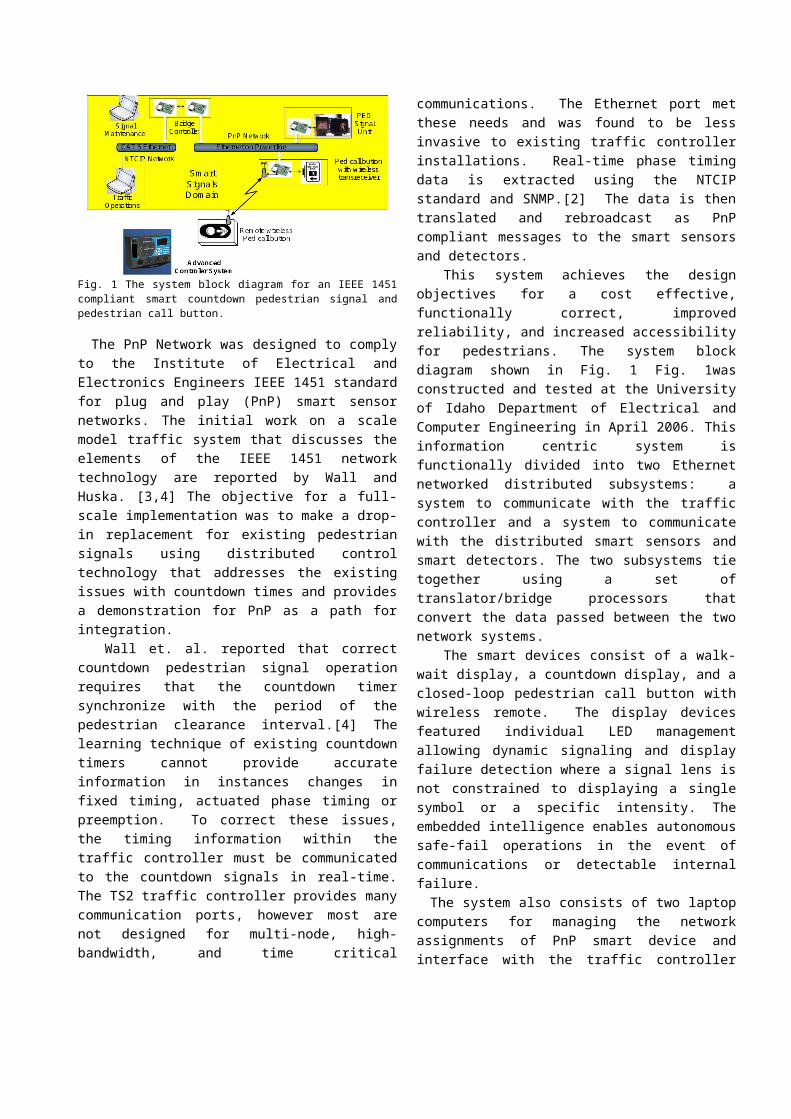
were implemented with smart signal design leaving the traffic lights under conventional traffic control operations. Fig. 1 is a block diagram of the distributed traffic system architecture that was built and tested for this investigation. It consists of two independent Ethernet networks: one to provide communications with the traffic controller to read and modify NTCIP objects used in the timing algorithm and one network for the real-time control of the distributed smart signals.[2] The NTCIP Network used two laptops for simulation and configuration. The Traffic Operations laptop generates messages to altered traffic signal timing representative of control from a traffic operations center. The Signal Maintenance laptop is used to provide the connection logic between the traffic controller NTCIP objects and the physical signal devices. This logical connectivity is equivalent to routing conductors from the traffic controller cabinet and the signal devices in the intersection.
Fig. 1 The system block diagram for an IEEE 1451 compliant smart countdown pedestrian signal and pedestrian call button.
The PnP Network was designed to comply to the Institute of Electrical and Electronics Engineers IEEE 1451 standard for plug and play (PnP) smart sensor networks. The initial work on a scale model traffic system that discusses the elements of the IEEE 1451 network technology are reported by Wall and Huska. [3,4] The objective for a full-scale implementation was to make a drop-in replacement for existing pedestrian signals using distributed control technology that addresses the existing issues with countdown times and provides a demonstration for PnP as a path for integration.
Wall et. al. reported that correct countdown pedestrian signal operation requires that the countdown timer synchronize with the period of the pedestrian clearance interval.[4] The learning technique of existing countdown timers cannot provide accurate information in instances changes in fixed timing, actuated phase timing or preemption. To correct these issues, the timing information within the traffic controller must be communicated to the countdown signals in real-time. The TS2 traffic controller provides many communication ports, however most are not designed for multi-node, high-bandwidth, and time critical communications. The Ethernet port met these needs and
was found to be less invasive to existing traffic controller installations. Real-time phase timing data is extracted using the NTCIP standard and SNMP.[2] The data is then translated and rebroadcast as PnP compliant messages to the smart sensors and detectors.
This system achieves the design objectives for a cost effective, functionally correct, improved reliability, and increased accessibility for pedestrians. The system block diagram shown in Fig. 1 Fig. 1was constructed and tested at the University of Idaho Department of Electrical and Computer Engineering in April 2006. This information centric system is functionally divided into two Ethernet networked distributed subsystems: a system to communicate with the traffic controller and a system to communicate with the distributed smart sensors and smart detectors. The two subsystems tie together using a set of translator/bridge processors that convert the data passed between the two network systems.
The smart devices consist of a walk-wait display, a countdown display, and a closed-loop pedestrian call button with wireless remote. The display devices featured individual LED management allowing dynamic signaling and display failure detection where a signal lens is not constrained to displaying a single symbol or a specific intensity. The embedded intelligence enables autonomous safe-fail operations in the event of communications or detectable internal failure.
The system also consists of two laptop computers for managing the network assignments of PnP smart device and interface with the traffic controller Ethernet communications. The wiring of PnP smart signals and detectors is in effect accomplished in software using the user interface laptop. The Traffic Operations laptop shown in Fig. 1 is used for system testing during development to simulate incoming requests for signal-timing plan changes from a city's traffic department. This computer was also used to implement preemption and setup the timing plans in the traffic controller.
B. System CommunicationsCountdown timing and walk/wait state information are
polled from the traffic controller by the bridge SNMP controller and are translated and rebroadcast to the PnP network controller that distributes this information to the smart signals and detectors. The service request information from the smart pedestrian call button uses the same route, but transmits minimal information which is translated by the SNMP bridge controller before reaching the traffic controller. In this implementation, the bridge node consists of two microprocessors, a SNMP translator and a PnP processor, operating in a master-slave configuration bridging the two Ethernet networks. Network communications with the traffic controller use Simple Network Management Protocol (SNMP) employing a point-to-point UDP transport layer. All other devices use
standard network transmission control protocol (TCP) and user datagram protocol (UDP) broadcast communications where each network node uses dynamic host configuration protocol (DHCP) for a unique local internet protocol (IP) address allocation. The two networks could be replaced with a common network hub or switch. However, they are shown as two independent networks in Fig. 1 to give emphasis to the use of Ethernet over power line carrier. Every smart signal and detector as well as the translator and bridge processors operate as a network node.
1) Translator Controller to Traffic Controller Communications
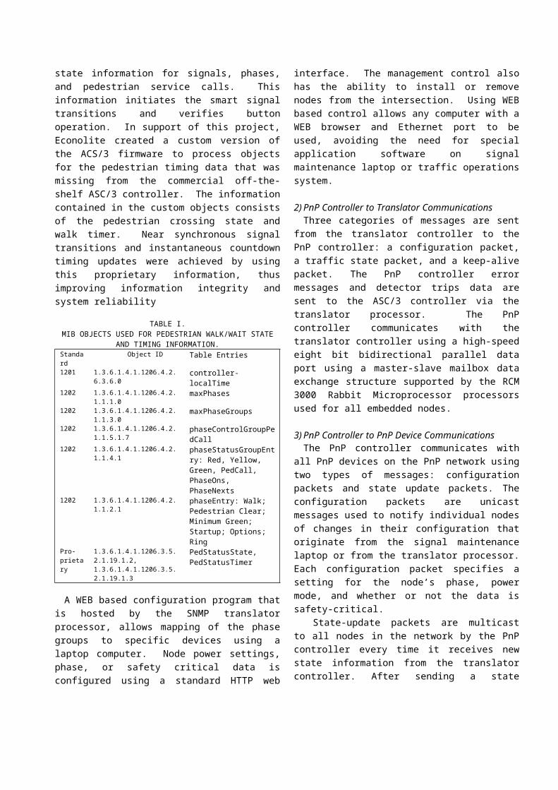
The primary function of the translator controller is to provide an interface between the traffic signal controller and the PnP traffic devices. We used Econolite’s ASC/3 2100 series NEMA Type 2 traffic controller that follows the NTCIP standard. Data is exchanged between the translator and the ASC/3 traffic controller using SNMP packets which consist of management information base (MIB) codes as defined in the NTCIP standard. The translator uses the 1201 and 1202 standard MIB objects to send and retrieve data from the traffic controller.[6][7] Table I. represents the MIB objects both read and set in management of the PnP nodes.
Upon startup of the bridge controller, critical information must be extracted for clock synchronization, proper signal configuration, and safe-fail operation. The first object includes the one from the 1201 standard representing the traffic controller clock value, controller-localTime. This time is used in stamping data log information on the bridge node. Secondly we use 1202 standard MIB objects which contain phase information, such as maximum phase values, phase cycle durations, safe-fail modes, and ring indication.
Following startup initializations the translator controller enters an infinite loop where the traffic controller is polled every 250 ms. Standard objects received from within the phaseStatusGroupEntry MIB node provide state information for signals, phases, and pedestrian service calls. This information initiates the smart signal transitions and verifies button operation. In support of this project, Econolite created a custom version of the ACS/3 firmware to process objects for the pedestrian timing data that was missing from the commercial off-the-shelf ASC/3 controller. The information contained in the custom objects consists of the pedestrian crossing state and walk timer. Near synchronous signal transitions and instantaneous countdown timing updates were achieved by using this proprietary information, thus improving information integrity and system reliability
TABLE I.MIB OBJECTS USED FOR PEDESTRIAN WALK/WAIT STATE AND
TIMING INFORMATION.Standard Object ID Table Entries1201 1.3.6.1.4.1.1206.4.2.6.3.6.0 controller-localTime
1202 1.3.6.1.4.1.1206.4.2.1.1.1.0 maxPhases1202 1.3.6.1.4.1.1206.4.2.1.1.3.0 maxPhaseGroups1202 1.3.6.1.4.1.1206.4.2.1.1.5.1.7 phaseControlGroupPedCall 1202 1.3.6.1.4.1.1206.4.2.1.1.4.1 phaseStatusGroupEntry:
Red, Yellow, Green, PedCall, PhaseOns, PhaseNexts
1202 1.3.6.1.4.1.1206.4.2.1.1.2.1 phaseEntry: Walk; Pedestrian Clear; Minimum Green; Startup; Options; Ring
Pro-prietary
1.3.6.1.4.1.1206.3.5.2.1.19.1.2,1.3.6.1.4.1.1206.3.5.2.1.19.1.3
PedStatusState, PedStatusTimer
A WEB based configuration program that is hosted by the SNMP translator processor, allows mapping of the phase groups to specific devices using a laptop computer. Node power settings, phase, or safety critical data is configured using a standard HTTP web interface. The management control also has the ability to install or remove nodes from the intersection. Using WEB based control allows any computer with a WEB browser and Ethernet port to be used, avoiding the need for special application software on signal maintenance laptop or traffic operations system.
2) PnP Controller to Translator CommunicationsThree categories of messages are sent from the translator
controller to the PnP controller: a configuration packet, a traffic state packet, and a keep-alive packet. The PnP controller error messages and detector trips data are sent to the ASC/3 controller via the translator processor. The PnP controller communicates with the translator controller using a high-speed eight bit bidirectional parallel data port using a master-slave mailbox data exchange structure supported by the RCM 3000 Rabbit Microprocessor processors used for all embedded nodes.
3) PnP Controller to PnP Device CommunicationsThe PnP controller communicates with all PnP devices
on the PnP network using two types of messages: configuration packets and state update packets. The configuration packets are unicast messages used to notify individual nodes of changes in their configuration that originate from the signal maintenance laptop or from the translator processor. Each configuration packet specifies a setting for the node’s phase, power mode, and whether or not the data is safety-critical.
State-update packets are multicast to all nodes in the network by the PnP controller every time it receives new state information from the translator controller. After sending a state update, the PnP controller waits until all safety critical nodes in the system respond to the update before sending another broadcast message acknowledging the commanded state. This type of message is called an “implement packet” that instructs the nodes to change state instantly upon receipt of the message.
There are also three broadcast messages that do not
contain traffic signal state information. There are heartbeat messages that simply indicate that the PnP device is still functioning. Another type of network message indicates that the PnP controller has detected a critical error in the intersection and instructs all of the nodes to transition into a safe-fail mode. The last type of network message is one that PnP controller sends when initializing to instruct all nodes on the network to transmit their electronic descriptions back so that the PnP controller can determine which nodes are connected.
The PnP controller periodically interrogates the status of each smart device. If the PnP controller receives an error message from a smart device or if a node does not respond in the appointed time window, the PnP controller passes that error message back to the translator controller to have that data saved in a log file. The error log is accessed from signal maintenance laptop through the WEB page hosted by the translation controller.
C.System HardwareRabbit Semiconductor RCM3000 series microprocessors
were used for all PnP smart sensor designs. The embedded network system consists of two Ethernet networks each requiring a network switch or hub and a data bridge in addition to one or more PnP networks nodes. When using Ethernet over power line (EoP) modems, no hub or switch is required for the PnP network. The bridge consisting of independent translator and PnP processors is needed because the RCM 3000 processors can only host one Ethernet port. Since this design uses two independent networks, two processors are required to bridge the two. The functionality of the two processors was allocated to level the processing burden for improved response performance.
The smart pedestrian devices are a drop-in-replaceable because no additional wires are required between the traffic controller cabinet and the devices, if EoP technology is utilized. The conductors required to supply power for the devices also become the medium for network communications. Although the system was tested using 10Mbps EoP modems, 200Mbps modems have since become commercially available.
1) Pedestrian SignalCommercial pedestrian signals use a standardized
housing. Therefore the PnP signal, which includes an EoP modem, light emitting diode (LED) array, and microprocessor, was designed to fit inside an empty Econolite housing.
The signals were designed to allow individual LED control, monitoring, and variable display intensity. Each LED is now treated as a user specified pixel and can be toggled independently. By having control of each individual LED in the display, symbols other than conventional numbers can be displayed to the user. These
smart signals are also able to detect and send alarms back to the controller in the event of a signal failure. Possible failures include LED burnout or disconnect and state update timeout. LED monitoring was designed with analog to digital convertors that capture the returning electrical current as each column of LEDs is toggled. The display intensity of the LEDs is controlled by the pulse width modulation (PWM) output of the microprocessor. Possible uses of variable intensity control include adaptively reducing energy requirements, increasing LED longevity, and reducing light pollution or interference. The PnP feature of the smart signal technology makes it possible for the signal to have electronic descriptions of the signals capability and performance characteristics.
The display configuration of the new smart countdown and walk-wait signal are shown in Fig. 2 and Fig. 3. The countdown timer display consists of two 8x16 LED matrices.
Fig. 2 LED placement for the PED Countdown timer
Fig. 3 LED placement for the PED Countdown timer
2) Pedestrian ButtonThe smart PnP pedestrian buttons communicate with the
traffic controller via the same network as the signals. The controller can provide feedback to the pedestrian button when a request for service is registered. It is anticipated that a visual, tactile, or audio display of this feedback will discourage physical abuse of the call button and encourage pedestrians to wait for the walk indication in lieu of making a hazardous and illegal attempt to cross the street. The smart pedestrian call button is also equipped with wireless remote receiver. It can handle requests by special needs users who have difficulty locating or accessing the call button. A low cost 400 MHz short range radio implemented the call request and feedback communications. As such, the system is able to differentiate pedestrian calls and provide different service based upon the needs of pedestrians requesting service. The wireless receiver could reside anywhere in the system, for example within the countdown signal where the radio signal would be more reliable.
D.Network Security ConsiderationsFor security network measures it is advisable to use a
router between any wide area network (WAN) and the local
area network. The architecture of the PnP smart signals system consists of two Ethernet network types. The PnP communication uses EoP which acts as a hub based network. The traffic controller communication uses category 5 Ethernet cable and utilizes switch based routing.
EoP was a convenient communication medium, but messages are broadcast across the entire intersection local network. Theoretically information could be accessed and possibly misused if this network does not employ security measures. Encryption and non-commercial modems are two measures considered in this project, but they were not implemented.
IV. RESULTSThe system was demonstrated at the University of Idaho
2006 Engineering Expo in April. With the constraints of very strict control over the network information flow, the system worked with no failures. The smart signal system countdown timer accurately displays the crossing time remaining during normal operations and dynamically updated for phase timing changes. The remaining clearance interval was also correctly displayed when the traffic controller timing was changed due to preemption. There were no observable transition lags in the walk/wait displays when compared to conventional units operating simultaneously.
Only a single smart pedestrian call button was implemented for all tests. This gave the conventional pedestrian signal the same call reference as the smart PnP pedestrian signal. Testing of inputs from a conventional call button was simulated using the signal maintenance laptop as an SNMP client to set the pedestrian call object.
Problems did arise during testing resulting from limitations of the 10Mbps power line Ethernet modems. Occasionally a data packet would be dropped because of excessive delays. This problem is exacerbated when multiple nodes power up or reboot simultaneously. The result was that only one node will be configured with the hub and the other will time out and require re-booting. When direct wire category 5 Ethernet cable replaced the EoP modems, the network speed increased sufficiently resulting in minimal delays in transmitting messages from the PnP Controller and each node, thus eliminating the problem.
The bridge has to request multiple large SNMP packets of information and then filter them to retrieve the correct information. There is considerable wasted time in retrieving information that has no use for the PnP system. A possible solution is to update the traffic controller configuration for dynamic objects to allow more precise information in one data broadcast.
Wireless Ethernet was also considered, however the associated security issues were beyond the scope of the project. Future developments could easily implement a
802.11 wireless standard into this design, perhaps even as a backup device for EoP modem failure. The project demonstrated that any medium for transmitting Ethernet messages could be used.
V. CONCLUSIONSThe project successfully developed proof-of-concept
prototypes for a distributed-signal-network of PnP traffic signal devices. TS2 traffic controllers with minor modifications can support both conventional and smart PnP traffic signal devices. The continuation of research for implementing IEEE 1451 in signalized intersections demonstrated network communication over power line carrier, traffic controller integration, single microcontroller IEEE 1451 operation, and improvements in accuracy and intersection services. The prototype IEEE 1451 compliant devices developed included a bridge controller for communication with traffic controller, variable intensity pedestrian crossing signals and countdown signals, and pedestrian crossing button with wireless button. Hosting a webpage for the maintenance of the PnP system does not require additional hardware or specialized software to be installed on laptop computers for maintenance and installation. Testing of the PnP network makes it reasonable to anticipate that recent advances in Ethernet over power line technology will resolve the issues addressed in the results above.
Traffic signals based upon PnP distributed sensor networks can support dynamic signage to facilitate temporal requirements for traffic control, thus providing better real-time traffic control that can result in safer and efficient traffic flow. Electronic descriptions in the smart transducer modules provided by the smart transducers simplify installations.
VI. DIRECTION OF CURRENT RESEARCHWith the success of the smart signals research being able
to correct the operations of the countdown pedestrian signal, the present research is focusing on pedestrian safety and access. Significant attention is being given to the making the system robust by including concepts of safety critical Ethernet and embedded network security. We are currently working with various groups representing pedestrians with disabilities to provide assistance in orientation and navigation. It is our intention to work with Federal Highway Administration researchers to integrate our pedestrian safety work with FWHA Vehicle Infrastructure Integration (VII) and Cooperative Intersection Collision Avoidance System (CICAS) initiatives.
ACKNOWLEDGMENT
Funding provided by the United States of America
Department of Transportation, Research and Special Programs Administration, Grant No. DTRS98-G-0027.
REFERENCES
[1] Wall, R. W. and A. Huska, “Design Platform for Plug-and-Play IEEE 1451 Traffic Signal,” The 31st Annual IEEE Industrial Electronics Conference, Raleigh, NC, Nov 6-10, 2005, Paper No. RD-001973.
[2] NTCIP 9001, “The NTCIP Guide ver 3. A Recommended Information Report of the Joint Commitee on NTCIP,” AASHTO, ITE, NEMA.
[3] Wall, R. W., A. Huska, and D. Bullock, “Application of Plug and Play Distributed Signal Technology to Traffic Signals,” Transportation Research Board 2006 Annual Meeting, Washington D.C., January 22-26, 2006, Paper No. 06-2728.
[4] Huska, A. “Application of Plug and Play Distributed Sensor Networks to Traffic Control Signals”, University of Idaho Master of Science Thesis, Computer Engineering, May, 2006
[5] Wall, R.W., T. Urbanik, D. Bullock, S. Allen, M. Busby, D. DeVoe, A. Huska, T. Rallens “Distributed Traffic Signal Control: Improving Pedestrian Control as A First Step” Transportation Research Board 2007 Annual Meeting, Washington D.C, Paper No. 07-0989.
[6] NTCIP 1201 v02.26, “Global Object Definitions,” AASHTO, ITE, NEMA, December 2002
[7] NTCIP 1202 v01.07d , “Object Definitions for Actuated Traffic Signal Controller (ASC) Unit,” AASHTO, ITE, NEMA, January 2005