Embed Size (px)
Citation preview
St. Louis Revit Users GroupSt. Louis Revit Users GroupSt. Louis Revit Users GroupSt. Louis Revit Users Group April 2014 Learning EventApril 2014 Learning EventApril 2014 Learning EventApril 2014 Learning Event
“All in the Family”“All in the Family”“All in the Family”“All in the Family” The Revit Family EditorThe Revit Family EditorThe Revit Family EditorThe Revit Family Editor ExposedExposedExposedExposed
Revit Family Editor Basics
Page | 1
STLRUG - www.stlrug.org
Introduction Families are the basic building blocks of the Autodesk Revit software platform. Almost every object
within Revit is based on a family definition. There are numerous types of families, which all serve
certain functions, and have certain uses. A basic understanding of Revit families, their types and uses,
and how to modify and create families is an essential skill in becoming a proficient Revit user. This
document serves to be a basic overview of Revit Families, the Revit Family Editor interface, and some
best practices for the creation of families, and is meant to be a precursor to the more advanced
discussion topics that will be covered at the April Learning Event.
Family Types Families have different uses and different capabilities within a Revit project. Therefore, there are
numerous types of families, that each requires different creation and editing techniques.
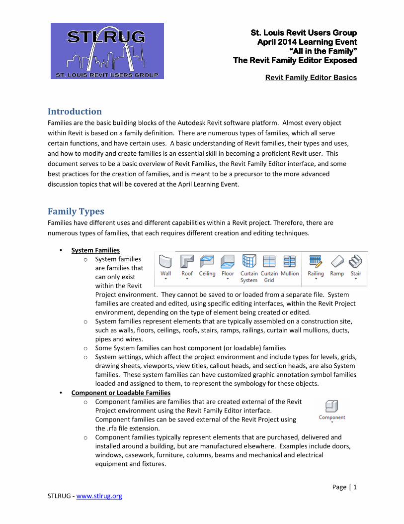
• System Families
o System families
are families that
can only exist
within the Revit
Project environment. They cannot be saved to or loaded from a separate file. System
families are created and edited, using specific editing interfaces, within the Revit Project
environment, depending on the type of element being created or edited.
o System families represent elements that are typically assembled on a construction site,
such as walls, floors, ceilings, roofs, stairs, ramps, railings, curtain wall mullions, ducts,
pipes and wires.
o Some System families can host component (or loadable) families
o System settings, which affect the project environment and include types for levels, grids,
drawing sheets, viewports, view titles, callout heads, and section heads, are also System
families. These system families can have customized graphic annotation symbol families
loaded and assigned to them, to represent the symbology for these objects.
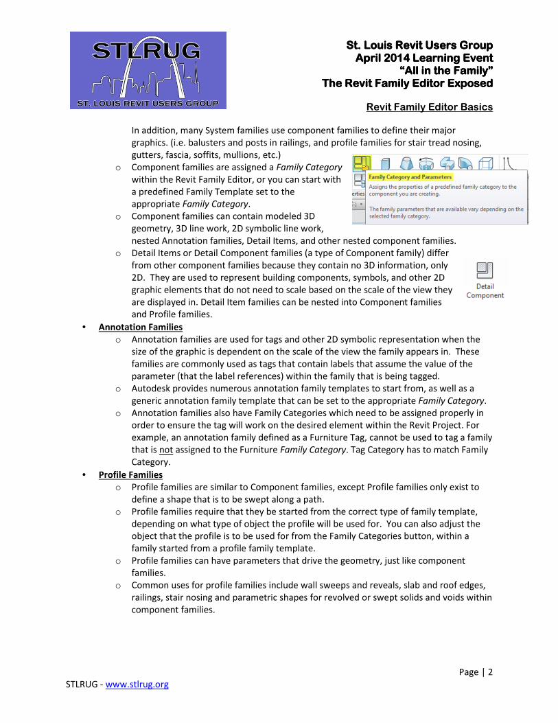
• Component or Loadable Families
o Component families are families that are created external of the Revit
Project environment using the Revit Family Editor interface.
Component families can be saved external of the Revit Project using
the .rfa file extension.
o Component families typically represent elements that are purchased, delivered and
installed around a building, but are manufactured elsewhere. Examples include doors,
windows, casework, furniture, columns, beams and mechanical and electrical
equipment and fixtures.
St. Louis Revit Users GroupSt. Louis Revit Users GroupSt. Louis Revit Users GroupSt. Louis Revit Users Group April 2014 Learning EventApril 2014 Learning EventApril 2014 Learning EventApril 2014 Learning Event
“All in the Family”“All in the Family”“All in the Family”“All in the Family” The Revit Family EditorThe Revit Family EditorThe Revit Family EditorThe Revit Family Editor ExposedExposedExposedExposed
Revit Family Editor Basics
Page | 2
STLRUG - www.stlrug.org
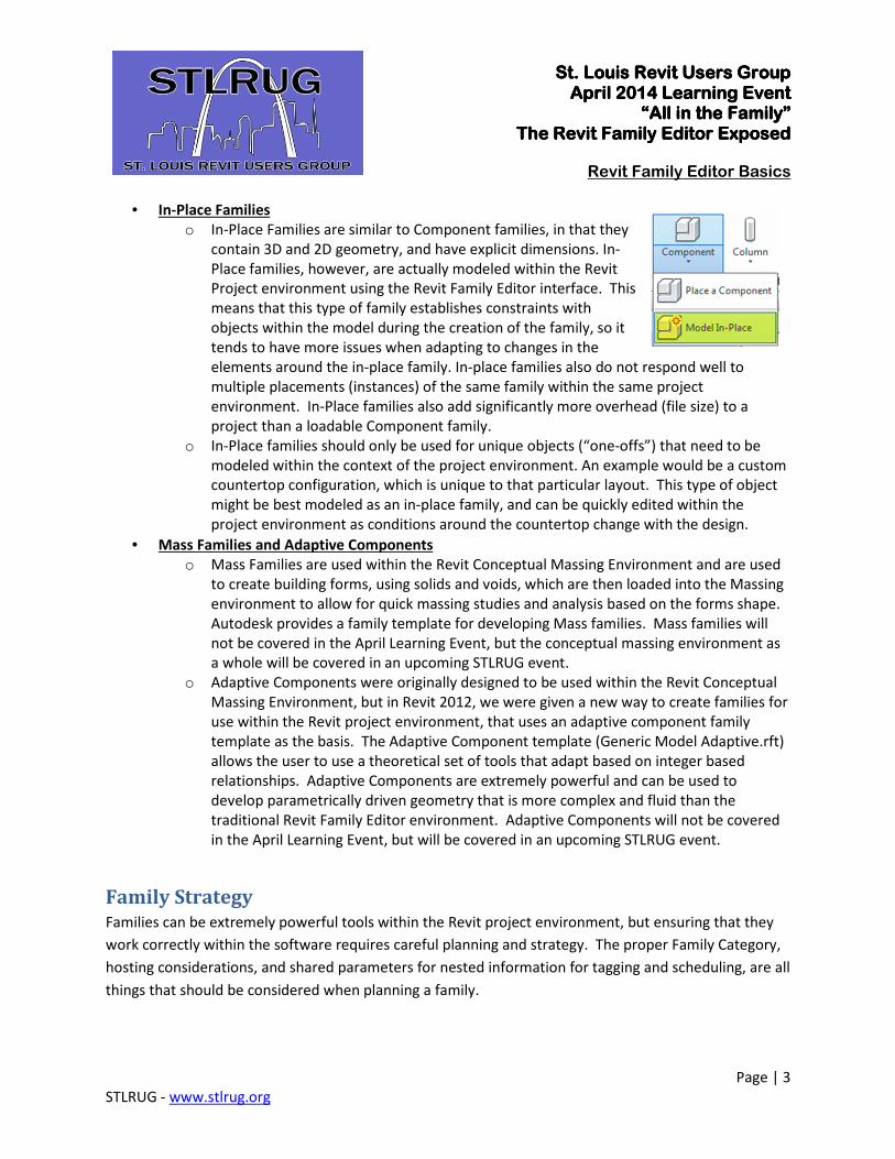
In addition, many System families use component families to define their major
graphics. (i.e. balusters and posts in railings, and profile families for stair tread nosing,
gutters, fascia, soffits, mullions, etc.)
o Component families are assigned a Family Category
within the Revit Family Editor, or you can start with
a predefined Family Template set to the
appropriate Family Category.
o Component families can contain modeled 3D
geometry, 3D line work, 2D symbolic line work,
nested Annotation families, Detail Items, and other nested component families.
o Detail Items or Detail Component families (a type of Component family) differ
from other component families because they contain no 3D information, only
2D. They are used to represent building components, symbols, and other 2D
graphic elements that do not need to scale based on the scale of the view they
are displayed in. Detail Item families can be nested into Component families
and Profile families.
• Annotation Families
o Annotation families are used for tags and other 2D symbolic representation when the
size of the graphic is dependent on the scale of the view the family appears in. These
families are commonly used as tags that contain labels that assume the value of the
parameter (that the label references) within the family that is being tagged.
o Autodesk provides numerous annotation family templates to start from, as well as a
generic annotation family template that can be set to the appropriate Family Category.
o Annotation families also have Family Categories which need to be assigned properly in
order to ensure the tag will work on the desired element within the Revit Project. For
example, an annotation family defined as a Furniture Tag, cannot be used to tag a family
that is not assigned to the Furniture Family Category. Tag Category has to match Family
Category.
• Profile Families
o Profile families are similar to Component families, except Profile families only exist to
define a shape that is to be swept along a path.
o Profile families require that they be started from the correct type of family template,
depending on what type of object the profile will be used for. You can also adjust the
object that the profile is to be used for from the Family Categories button, within a
family started from a profile family template.
o Profile families can have parameters that drive the geometry, just like component
families.
o Common uses for profile families include wall sweeps and reveals, slab and roof edges,
railings, stair nosing and parametric shapes for revolved or swept solids and voids within
component families.
St. Louis Revit Users GroupSt. Louis Revit Users GroupSt. Louis Revit Users GroupSt. Louis Revit Users Group April 2014 Learning EventApril 2014 Learning EventApril 2014 Learning EventApril 2014 Learning Event
“All in the Family”“All in the Family”“All in the Family”“All in the Family” The Revit Family EditorThe Revit Family EditorThe Revit Family EditorThe Revit Family Editor ExposedExposedExposedExposed
Revit Family Editor Basics
Page | 3
STLRUG - www.stlrug.org
• In-Place Families
o In-Place Families are similar to Component families, in that they
contain 3D and 2D geometry, and have explicit dimensions. In-
Place families, however, are actually modeled within the Revit
Project environment using the Revit Family Editor interface. This
means that this type of family establishes constraints with
objects within the model during the creation of the family, so it
tends to have more issues when adapting to changes in the
elements around the in-place family. In-place families also do not respond well to
multiple placements (instances) of the same family within the same project
environment. In-Place families also add significantly more overhead (file size) to a
project than a loadable Component family.
o In-Place families should only be used for unique objects (“one-offs”) that need to be
modeled within the context of the project environment. An example would be a custom
countertop configuration, which is unique to that particular layout. This type of object
might be best modeled as an in-place family, and can be quickly edited within the
project environment as conditions around the countertop change with the design.
• Mass Families and Adaptive Components
o Mass Families are used within the Revit Conceptual Massing Environment and are used
to create building forms, using solids and voids, which are then loaded into the Massing
environment to allow for quick massing studies and analysis based on the forms shape.
Autodesk provides a family template for developing Mass families. Mass families will
not be covered in the April Learning Event, but the conceptual massing environment as
a whole will be covered in an upcoming STLRUG event.
o Adaptive Components were originally designed to be used within the Revit Conceptual
Massing Environment, but in Revit 2012, we were given a new way to create families for
use within the Revit project environment, that uses an adaptive component family
template as the basis. The Adaptive Component template (Generic Model Adaptive.rft)
allows the user to use a theoretical set of tools that adapt based on integer based
relationships. Adaptive Components are extremely powerful and can be used to
develop parametrically driven geometry that is more complex and fluid than the
traditional Revit Family Editor environment. Adaptive Components will not be covered
in the April Learning Event, but will be covered in an upcoming STLRUG event.
Family Strategy Families can be extremely powerful tools within the Revit project environment, but ensuring that they
work correctly within the software requires careful planning and strategy. The proper Family Category,
hosting considerations, and shared parameters for nested information for tagging and scheduling, are all
things that should be considered when planning a family.
St. Louis Revit Users GroupSt. Louis Revit Users GroupSt. Louis Revit Users GroupSt. Louis Revit Users Group April 2014 Learning EventApril 2014 Learning EventApril 2014 Learning EventApril 2014 Learning Event
“All in the Family”“All in the Family”“All in the Family”“All in the Family” The Revit Family EditorThe Revit Family EditorThe Revit Family EditorThe Revit Family Editor ExposedExposedExposedExposed
Revit Family Editor Basics
Page | 4
STLRUG - www.stlrug.org
• Family Category
o The proper Family Category assignment defines how Revit will see and use the loaded
component family, and is critical to the correct functionality of the component. Careful
consideration should be given to the correct Family Category assignment. For example,
an Electrical Panel board family assigned to the Generic Model Family Category will not
function as a panel board within the software. In addition, Revit adds certain family
category-specific parameters to the family based on its Family Category assignment.
These Family parameters define behaviors or Identity Data that apply across all types in
that family. Different categories have different family parameters based on how Revit
expects the component to be used.
• Family Templates
o Autodesk provides a series of Family Templates with the standard installation of Revit.
These Family Templates are preset to the proper Family Category and there are
numerous varieties of templates for the various types of hosts. (i.e. Wall Hosted, Ceiling
Hosted, etc.) In addition there are Generic Model Templates for the various types of
hosts, which can then be set to the proper Family Category to ensure proper
functionality in the software. These Family Templates can be found at
“C:\ProgramData\Autodesk\RVT XXXX (Version)\Family Templates\” when Revit is
installed in its default location. Family Template files use the .rft file extension.
o In addition to the Family Category specific parameters that a Family Template provides,
some templates also have predefined Subcategories for different parts of the object.
For example, the Door Family Template has subcategories defined for Frame/Mullion,
Panel, Plan Swing, Elevation Swing, etc. These subcategories allow for different graphics
settings for different parts of the family.
o A good practice is to start from one of the Autodesk provided Family Templates and
then modify that template to include the desired Reference Planes, constraints, and
required Shared Parameters for your company, and then save that as a Family Template
from which Standard company content is created from.
• Family Planning
o Effective Family creation requires planning and thought as to the function, units,
hosting, graphics, parametric control, and embedded information desired for the family.
The following are some basic questions for information gathering when planning a
family:
� What is the family’s role or function?
• Is this a door, an electrical fixture, a structural beam shape, or an
annotation family or tag? This decision will affect the Family Template
St. Louis Revit Users GroupSt. Louis Revit Users GroupSt. Louis Revit Users GroupSt. Louis Revit Users Group April 2014 Learning EventApril 2014 Learning EventApril 2014 Learning EventApril 2014 Learning Event
“All in the Family”“All in the Family”“All in the Family”“All in the Family” The Revit Family EditorThe Revit Family EditorThe Revit Family EditorThe Revit Family Editor ExposedExposedExposedExposed
Revit Family Editor Basics
Page | 5
STLRUG - www.stlrug.org
to start with, as well as the required Family Category that the object
must be assigned to function properly in Revit.
� How does the family need to interact with other components in the project?
• Does the object need to attach to another component in the project
such as a wall, ceiling, or floor? If so, then additional consideration must
be given to who will be inserting the content. For example, if the family
you are creating is a ceiling based light fixture, the natural tendency
would be to use a ceiling based Family Template to create the object.
However, if the Electrical Engineer, who will be inserting the fixture,
simply has the Architectural model linked in to his model, then the
ceilings will not exist in his model so there is no host for the ceiling-
based light fixture. Possible alternates are Level-based or face-based
families, which are not dependent on a certain type of host. The
decision to use an object hosted template should be weighed carefully
and is typically only used when the object needs to create an opening in
its host. Keep in mind that an object created with an object hosted
template cannot be switched to a non-hosted template. The family
would need to be rebuilt starting with the correct hosted template.
• If the object is to be used in a MEP system (i.e. Electrical, Duct or Pipe),
then it would also need to have the appropriate connectors to allow the
object to be connected to that system within the Revit project
environment. Similarly, if the object is a structural element that would
need to be used in analysis, the appropriate node definitions and
analytical lines would need to be made in the family.
� How does this family need to appear graphically in the Project environment?
• Does the family need different graphic displays for the differing levels of
detail? (Coarse, Medium and Fine)
• Does the family need a symbolic representation in plan in lieu of the 3D
geometry? For example, an Electrical Outlet family typically will display
a symbol for Electrical Plans, but the Architects might want to see the
actual geometry in lieu of the symbol. A strategy, which displays the
symbol at coarse and medium level of detail, and the 3D geometry at
Fine level of detail, may be used.
• Is a simpler graphical representation desired in plan in lieu of the 3D
geometry display? If so, symbolic lines can be added to display in plan
views, while the 3D geometry can be set to be hidden in plan views.
St. Louis Revit Users GroupSt. Louis Revit Users GroupSt. Louis Revit Users GroupSt. Louis Revit Users Group April 2014 Learning EventApril 2014 Learning EventApril 2014 Learning EventApril 2014 Learning Event
“All in the Family”“All in the Family”“All in the Family”“All in the Family” The Revit Family EditorThe Revit Family EditorThe Revit Family EditorThe Revit Family Editor ExposedExposedExposedExposed
Revit Family Editor Basics
Page | 6
STLRUG - www.stlrug.org
� Does the family have different sizes or information that needs to be able to
adjust to certain conditions or options?
• This question is used to determine whether a family should have
parametric controls setup using dimensions, constraints and parameters
to control the geometry or information and allow for different sizes and
styles to be created. If multiple sizes or types of the object are not
needed and the family is simply static geometry and information, then
parameters and constraints may not be needed. This will simplify the
effort required to build the family. If parametric control of the objects is
desired, additional planning is required to determine which parameters
need to be flexible and what sizes and information are required. In
addition, thought should be given to the names of the parameters as
well as whether to use shared parameters for these options, in case the
information needs to be scheduled or tagged.
• The information portion of a family is another item that must be
considered carefully when creating a family. Is there information that
can be contained within the family that I can use in scheduling or
estimating? Is there information that a consulting engineer would be
interested in, that can be embedded and shared via parameters within
the family? Parameters can be created (and shared, if desired) with
multiple families and disciplines. This allows for streamlined
coordination and collaboration with the correct planning and
implementation strategy.
• Parametric Family Creation Workflow
If the Family Planning process has pointed you to the need to create family a with parametric
controls for the geometry, then in order to be successful, a user must create the right hierarchy
of elements and constraints for those elements. The following is an analogy to help you
understand the best practice for creating parametrically flexible families:
o Build the “Bones” first - The “Bones” in a Revit Family consist of the Reference Planes
and Lines that define the extents of the geometry and the objects that need to be
controlled parametrically.
o Build the “Muscles” second - The “Muscles” within a Revit Family consist of the
dimensions, parameters and constraints that will drive or control the “Bones”.
o “Flex” the Family - “Flexing” involves changing the values of parameters that control
geometry to make sure the objects are moving in the desired relationships and
directions. Best practice is to “flex” a parameter as soon as you establish the controls,
St. Louis Revit Users GroupSt. Louis Revit Users GroupSt. Louis Revit Users GroupSt. Louis Revit Users Group April 2014 Learning EventApril 2014 Learning EventApril 2014 Learning EventApril 2014 Learning Event
“All in the Family”“All in the Family”“All in the Family”“All in the Family” The Revit Family EditorThe Revit Family EditorThe Revit Family EditorThe Revit Family Editor ExposedExposedExposedExposed
Revit Family Editor Basics
Page | 7
STLRUG - www.stlrug.org
dimensions or constraints. This makes it easier to diagnose problems with each
additional added parameter. Flex early and Flex often!!
o Build the “Skin” last - The Skin in a Revit Family is the geometry and line work added to
the family and constrained to the “Bones”. Remember to Flex the family after each
piece of added geometry to ensure that the components are moving as desired.
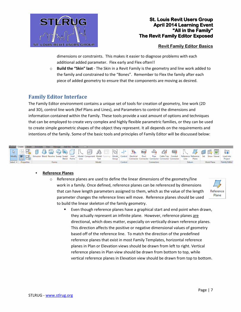
Family Editor Interface The Family Editor environment contains a unique set of tools for creation of geometry, line work (2D
and 3D), control line work (Ref Plans and Lines), and Parameters to control the dimensions and
information contained within the Family. These tools provide a vast amount of options and techniques
that can be employed to create very complex and highly flexible parametric families, or they can be used
to create simple geometric shapes of the object they represent. It all depends on the requirements and
intentions of the family. Some of the basic tools and principles of Family Editor will be discussed below:
• Reference Planes
o Reference planes are used to define the linear dimensions of the geometry/line
work in a family. Once defined, reference planes can be referenced by dimensions
that can have length parameters assigned to them, which as the value of the length
parameter changes the reference lines will move. Reference planes should be used
to build the linear skeleton of the family geometry.
� Even though reference planes have a graphical start and end point when drawn,
they actually represent an infinite plane. However, reference planes are
directional, which does matter, especially on vertically drawn reference planes.
This direction affects the positive or negative dimensional values of geometry
based off of the reference line. To match the direction of the predefined
reference planes that exist in most Family Templates, horizontal reference
planes in Plan or Elevation views should be drawn from left to right. Vertical
reference planes in Plan view should be drawn from bottom to top, while
vertical reference planes in Elevation view should be drawn from top to bottom.
St. Louis Revit Users GroupSt. Louis Revit Users GroupSt. Louis Revit Users GroupSt. Louis Revit Users Group April 2014 Learning EventApril 2014 Learning EventApril 2014 Learning EventApril 2014 Learning Event
“All in the Family”“All in the Family”“All in the Family”“All in the Family” The Revit Family EditorThe Revit Family EditorThe Revit Family EditorThe Revit Family Editor ExposedExposedExposedExposed
Revit Family Editor Basics
Page | 8
STLRUG - www.stlrug.org
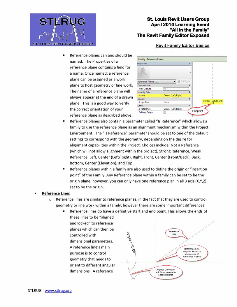
� Reference planes can and should be
named. The Properties of a
reference plane contains a field for
a name. Once named, a reference
plane can be assigned as a work
plane to host geometry or line work.
The name of a reference plane will
always appear at the end of a drawn
plane. This is a good way to verify
the correct orientation of your
reference plane as described above.
� Reference planes also contain a parameter called “Is Reference” which allows a
family to use the reference plane as an alignment mechanism within the Project
Environment. The “Is Reference” parameter should be set to one of the default
settings to correspond with the geometry, depending on the desire for
alignment capabilities within the Project. Choices include: Not a Reference
(which will not allow alignment within the project), Strong Reference, Weak
Reference, Left, Center (Left/Right), Right, Front, Center (Front/Back), Back,
Bottom, Center (Elevation), and Top.
� Reference planes within a family are also used to define the origin or “insertion
point” of the Family. Any Reference plane within a family can be set to be the
origin plane, however, you can only have one reference plan in all 3 axis (X,Y,Z)
set to be the origin.
• Reference Lines
o Reference lines are similar to reference planes, in the fact that they are used to control
geometry or line work within a family, however there are some important differences:
� Reference lines do have a definitive start and end point. This allows the ends of
these lines to be “aligned
and locked” to reference
planes which can then be
controlled with
dimensional parameters.
A reference line’s main
purpose is to control
geometry that needs to
orient to different angular
dimensions. A reference
St. Louis Revit Users GroupSt. Louis Revit Users GroupSt. Louis Revit Users GroupSt. Louis Revit Users Group April 2014 Learning EventApril 2014 Learning EventApril 2014 Learning EventApril 2014 Learning Event
“All in the Family”“All in the Family”“All in the Family”“All in the Family” The Revit Family EditorThe Revit Family EditorThe Revit Family EditorThe Revit Family Editor ExposedExposedExposedExposed
Revit Family Editor Basics
Page | 9
STLRUG - www.stlrug.org
line can be drawn at an angle to a reference plane (with one endpoint “aligned
and locked” to an intersection of two reference planes, an angular dimension
can then be assigned a parameter that allows for rotation of the reference line
around the axis of the reference plane intersection.
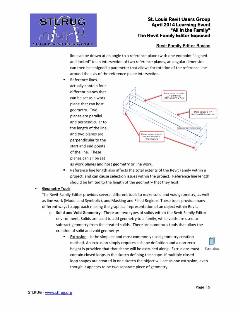
� Reference lines
actually contain four
different planes that
can be set as a work
plane that can host
geometry. Two
planes are parallel
and perpendicular to
the length of the line,
and two planes are
perpendicular to the
start and end points
of the line. These
planes can all be set
as work planes and host geometry or line work.
� Reference line length also affects the total extents of the Revit Family within a
project, and can cause selection issues within the project. Reference line length
should be limited to the length of the geometry that they host.
• Geometry Tools
The Revit Family Editor provides several different tools to make solid and void geometry, as well
as line work (Model and Symbolic), and Masking and Filled Regions. These tools provide many
different ways to approach making the graphical representation of an object within Revit.
o Solid and Void Geometry - There are two types of solids within the Revit Family Editor
environment. Solids are used to add geometry to a family, while voids are used to
subtract geometry from the created solids. There are numerous tools that allow the
creation of solid and void geometry:
� Extrusion - Is the simplest and most commonly used geometry creation
method. An extrusion simply requires a shape definition and a non-zero
height is provided that that shape will be extruded along. Extrusions must
contain closed loops in the sketch defining the shape. If multiple closed
loop shapes are created in one sketch the object will act as one extrusion, even
though it appears to be two separate piece of geometry.
St. Louis Revit Users GroupSt. Louis Revit Users GroupSt. Louis Revit Users GroupSt. Louis Revit Users Group April 2014 Learning EventApril 2014 Learning EventApril 2014 Learning EventApril 2014 Learning Event
“All in the Family”“All in the Family”“All in the Family”“All in the Family” The Revit Family EditorThe Revit Family EditorThe Revit Family EditorThe Revit Family Editor ExposedExposedExposedExposed
Revit Family Editor Basics
Page | 10
STLRUG - www.stlrug.org
� Blend - Similar to an extrusion, but a blend requires two shape definitions,
one for the base and one for the top of the blend. The shape of the blend
will change from one profile to the other over the distance set for the
depth. The two shape definitions must be in single closed loops, multiple
closed loops are not supported by the blend command.
� Revolve - A revolve is used to create geometry that is rounded. It requires a
defined axis and a profile shape. The profile is then extruded around the
defined axis creating a rounded shape based on the profile. You can then
tell the revolve how far around the axis that you would like the profile
extruded, from 1-360 degrees, depending on the shape that you desire.
Profile sketches defining the revolve shape can contain multiple closed loops.
� Sweep - A sweep is similar to an extrusion, except that in a sweep you define a
path that a shape is extruded along. A sweep has two components, the path
and the profile. The profile can be defined as a sketch in place, or a loaded
profile family can be used to define the shape. The path can be defined by
sketching the path in place, or lines can be picked from the edges of a
parametric solid or void, or any reference lines within the family. If a path
is picked from a line that is controlled by parameters, the path can grow or
shorten based on the dimensions of the object the path was picked from. This
allows sweeps to parametrically change based on the objects that define the
path of the sweep. A sweep can only contain one continuous path, and can be
opened or closed depending on the desired shape of the geometry. A sketched
path can only exist on one plane, while a picked path can be in multiple planes.
� Swept Blend - As the name implies, a swept blend combines the blend and
sweep tools into one. The path is sketched or picked, similar to the sweep
command, but with the swept blend, you can sketch or use loaded profiles to
define the start and end shapes, and the shape will change from one profile
to the other along the length of the path.
o Model and Symbolic Lines - The Family Editor also provides a couple of ways to draw
line work within a family. Model Lines and Symbolic Lines can be drawn using all of the
basic creation tools available to Detail and Model lines within the Project environment.
� Model Lines - Are lines that exist in 3D space and can appear in all views
including 3D views. Model lines can be hosted to levels, or a workplane that
has been made active which could be a reference plane or line or the face of
other 3D geometry within the family. Model lines are used to add extra detail
to modeled geometry that will still show up in 3D views.
St. Louis Revit Users GroupSt. Louis Revit Users GroupSt. Louis Revit Users GroupSt. Louis Revit Users Group April 2014 Learning EventApril 2014 Learning EventApril 2014 Learning EventApril 2014 Learning Event
“All in the Family”“All in the Family”“All in the Family”“All in the Family” The Revit Family EditorThe Revit Family EditorThe Revit Family EditorThe Revit Family Editor ExposedExposedExposedExposed
Revit Family Editor Basics
Page | 11
STLRUG - www.stlrug.org
� Symbolic Lines - Are lines that exist only in 2D space and only appear in views
that are parallel to the view in which they were created. Symbolic lines can
only be drawn in Plan, Elevation or Section views of the family. Symbolic
lines are used to add additional detail in Plan, Elevation and Section views.
Symbolic lines are also used to convey a simplified representation of an
object in Plan, Elevation and Section views, with the 3D geometry in the
family set to only show in 3D views. This allows a complex piece of geometry to
be shown in 3D views for renderings
o Masking Regions, Detail Components and Symbols - The Family Editor also provides
tools for creating Filled Regions (Hatch) and Masking Regions as well as Nested Detail
Components and Symbols. These tools are used to add detail and symbology to a
family.
� Masking Regions - Masking Regions are used to obscure model elements behind
the inserted family element. They are a 2 dimensional, view specific graphics
that contains a line style for the boundary and a region that will obscure
objects that are below it. Masking Regions are used in families where the
3D modeled geometry is turned off in planer views such as, Plan, Elevation
and Section, and the object is represented as line work. This line work will
not obscure other modeled elements within the project, so a Masking Region is
used to define the perimeter line work, which will then obscure other modeled
elements within the project environment. For example, the 3D modeled
geometry of a Water Closet family is turned off in Plan view, you draw 2D
Symbolic line work in Plan view to represent the Water Closet and load into a
project. The Water Closet is placed on a tile patterned floor in a restroom. The
tile pattern will show through the line work from the family. You re-edit the
family and add a Masking Region for the perimeter line work, and reload the
family. Now the tile pattern does not show through the Water Closet because
the Masking Region is obscuring the geometry below.
� Filled Regions - Filled Regions are similar to Hatch in AutoCAD. Filled
Regions are a 2 dimensional, view specific graphic that contain a line style
for the boundary and a fill pattern definition within that boundary.
• The Fill Patterns command is only available in Annotation families.
If filled regions are desired within a 3D component family, then a
separate Detail Component family must be created that contains the
filled region (which, can be parametrically controlled, to make it
“stretchable”), then that Detail Component can be loaded into the
St. Louis Revit Users GroupSt. Louis Revit Users GroupSt. Louis Revit Users GroupSt. Louis Revit Users Group April 2014 Learning EventApril 2014 Learning EventApril 2014 Learning EventApril 2014 Learning Event
“All in the Family”“All in the Family”“All in the Family”“All in the Family” The Revit Family EditorThe Revit Family EditorThe Revit Family EditorThe Revit Family Editor ExposedExposedExposedExposed
Revit Family Editor Basics
Page | 12
STLRUG - www.stlrug.org
component family and placed as an instance. The Detail Component is
still a 2D, view specific element.
• The Fill Patterns assigned to Filled Regions come in two types: Model
Patterns and Drafting Patterns. Model Patterns are based on a unit of
measure and are drawn at real world dimensions. A Drafting Pattern
will scale up and down based on the scale of the view that it appears in.
• Fill Patterns can also be set to transparent or opaque. A pattern set to
opaque will also work similar to a masking region by, hiding elements
below it in the project environment.
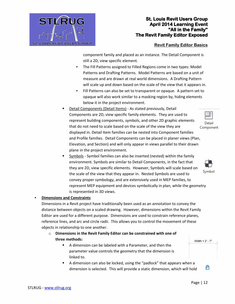
� Detail Components (Detail Items) - As stated previously, Detail
Components are 2D, view specific family elements. They are used to
represent building components, symbols, and other 2D graphic elements
that do not need to scale based on the scale of the view they are
displayed in. Detail Item families can be nested into Component families
and Profile families. Detail Components can be placed in planer views (Plan,
Elevation, and Section) and will only appear in views parallel to their drawn
plane in the project environment.
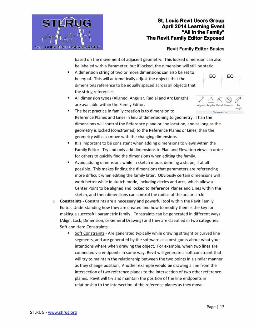
� Symbols - Symbol families can also be inserted (nested) within the family
environment. Symbols are similar to Detail Components, in the fact that
they are 2D, view specific elements. However, Symbols will scale based on
the scale of the view that they appear in. Nested Symbols are used to
convey proper symbology, and are extensively used in MEP families, to
represent MEP equipment and devices symbolically in plan, while the geometry
is represented in 3D views.
• Dimensions and Constraints
Dimensions in a Revit project have traditionally been used as an annotation to convey the
distance between objects on a scaled drawing. However, dimensions within the Revit Family
Editor are used for a different purpose. Dimensions are used to constrain reference planes,
reference lines, and arc and circle radii. This allows you to control the movement of these
objects in relationship to one another.
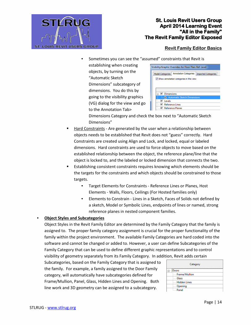
o Dimensions in the Revit Family Editor can be constrained with one of
three methods:
� A dimension can be labeled with a Parameter, and then the
parameter value controls the geometry that the dimension is
linked to.
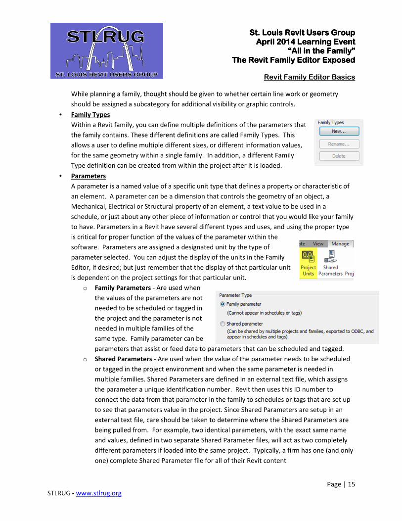
� A dimension can also be locked, using the “padlock” that appears when a
dimension is selected. This will provide a static dimension, which will hold
St. Louis Revit Users GroupSt. Louis Revit Users GroupSt. Louis Revit Users GroupSt. Louis Revit Users Group April 2014 Learning EventApril 2014 Learning EventApril 2014 Learning EventApril 2014 Learning Event
“All in the Family”“All in the Family”“All in the Family”“All in the Family” The Revit Family EditorThe Revit Family EditorThe Revit Family EditorThe Revit Family Editor ExposedExposedExposedExposed
Revit Family Editor Basics
Page | 13
STLRUG - www.stlrug.org
based on the movement of adjacent geometry. This locked dimension can also
be labeled with a Parameter, but if locked, the dimension will still be static.
� A dimension string of two or more dimensions can also be set to
be equal. This will automatically adjust the objects that the
dimensions reference to be equally spaced across all objects that
the string references.
� All dimension types (Aligned, Angular, Radial and Arc Length)
are available within the Family Editor.
� The best practice in family creation is to dimension to
Reference Planes and Lines in lieu of dimensioning to geometry. Than the
dimensions will control the Reference plane or line location, and as long as the
geometry is locked (constrained) to the Reference Planes or Lines, than the
geometry will also move with the changing dimensions.
� It is important to be consistent when adding dimensions to views within the
Family Editor. Try and only add dimensions to Plan and Elevation views in order
for others to quickly find the dimensions when editing the family.
� Avoid adding dimensions while in sketch mode, defining a shape, if at all
possible. This makes finding the dimensions that parameters are referencing
more difficult when editing the family later. Obviously certain dimensions will
work better while in sketch mode, including circles and arcs, which allow a
Center Point to be aligned and locked to Reference Planes and Lines within the
sketch, and then dimensions can control the radius of the arc or circle.
o Constraints - Constraints are a necessary and powerful tool within the Revit Family
Editor. Understanding how they are created and how to modify them is the key for
making a successful parametric family. Constraints can be generated in different ways
(Align, Lock, Dimension, or General Drawing) and they are classified in two categories:
Soft and Hard Constraints.
� Soft Constraints - Are generated typically while drawing straight or curved line
segments, and are generated by the software as a best guess about what your
intentions where when drawing the object. For example, when two lines are
connected via endpoints in some way, Revit will generate a soft constraint that
will try to maintain the relationship between the two points in a similar manner
as they change position. Another example would be drawing a line from the
intersection of two reference planes to the intersection of two other reference
planes. Revit will try and maintain the position of the line endpoints in
relationship to the intersection of the reference planes as they move.
St. Louis Revit Users GroupSt. Louis Revit Users GroupSt. Louis Revit Users GroupSt. Louis Revit Users Group April 2014 Learning EventApril 2014 Learning EventApril 2014 Learning EventApril 2014 Learning Event
“All in the Family”“All in the Family”“All in the Family”“All in the Family” The Revit Family EditorThe Revit Family EditorThe Revit Family EditorThe Revit Family Editor ExposedExposedExposedExposed
Revit Family Editor Basics
Page | 14
STLRUG - www.stlrug.org
• Sometimes you can see the “assumed” constraints that Revit is
establishing when creating
objects, by turning on the
“Automatic Sketch
Dimensions” subcategory of
dimensions. You do this by
going to the visibility graphics
(VG) dialog for the view and go
to the Annotation Tab>
Dimensions Category and check the box next to “Automatic Sketch
Dimensions”
� Hard Constraints - Are generated by the user when a relationship between
objects needs to be established that Revit does not “guess” correctly. Hard
Constraints are created using Align and Lock, and locked, equal or labeled
dimensions. Hard constraints are used to force objects to move based on the
established relationship between the object, the reference plane/line that the
object is locked to, and the labeled or locked dimension that connects the two.
� Establishing consistent constraints requires knowing which elements should be
the targets for the constraints and which objects should be constrained to those
targets.
• Target Elements for Constraints - Reference Lines or Planes, Host
Elements - Walls, Floors, Ceilings (For Hosted families only)
• Elements to Constrain - Lines in a Sketch, Faces of Solids not defined by
a sketch, Model or Symbolic Lines, endpoints of lines or named, strong
reference planes in nested component families.
• Object Styles and Subcategories
Object Styles in the Revit Family Editor are determined by the Family Category that the family is
assigned to. The proper family category assignment is crucial for the proper functionality of the
family within the project environment. The available Family Categories are hard coded into the
software and cannot be changed or added to. However, a user can define Subcategories of the
Family Category that can be used to define different graphic representations and to control
visibility of geometry separately from its Family Category. In addition, Revit adds certain
Subcategories, based on the Family Category that is assigned to
the family. For example, a family assigned to the Door Family
category, will automatically have subcategories defined for
Frame/Mullion, Panel, Glass, Hidden Lines and Opening. Both
line work and 3D geometry can be assigned to a subcategory.
St. Louis Revit Users GroupSt. Louis Revit Users GroupSt. Louis Revit Users GroupSt. Louis Revit Users Group April 2014 Learning EventApril 2014 Learning EventApril 2014 Learning EventApril 2014 Learning Event
“All in the Family”“All in the Family”“All in the Family”“All in the Family” The Revit Family EditorThe Revit Family EditorThe Revit Family EditorThe Revit Family Editor ExposedExposedExposedExposed
Revit Family Editor Basics
Page | 15
STLRUG - www.stlrug.org
While planning a family, thought should be given to whether certain line work or geometry
should be assigned a subcategory for additional visibility or graphic controls.
• Family Types
Within a Revit family, you can define multiple definitions of the parameters that
the family contains. These different definitions are called Family Types. This
allows a user to define multiple different sizes, or different information values,
for the same geometry within a single family. In addition, a different Family
Type definition can be created from within the project after it is loaded.
• Parameters
A parameter is a named value of a specific unit type that defines a property or characteristic of
an element. A parameter can be a dimension that controls the geometry of an object, a
Mechanical, Electrical or Structural property of an element, a text value to be used in a
schedule, or just about any other piece of information or control that you would like your family
to have. Parameters in a Revit have several different types and uses, and using the proper type
is critical for proper function of the values of the parameter within the
software. Parameters are assigned a designated unit by the type of
parameter selected. You can adjust the display of the units in the Family
Editor, if desired; but just remember that the display of that particular unit
is dependent on the project settings for that particular unit.
o Family Parameters - Are used when
the values of the parameters are not
needed to be scheduled or tagged in
the project and the parameter is not
needed in multiple families of the
same type. Family parameter can be
parameters that assist or feed data to parameters that can be scheduled and tagged.
o Shared Parameters - Are used when the value of the parameter needs to be scheduled
or tagged in the project environment and when the same parameter is needed in
multiple families. Shared Parameters are defined in an external text file, which assigns
the parameter a unique identification number. Revit then uses this ID number to
connect the data from that parameter in the family to schedules or tags that are set up
to see that parameters value in the project. Since Shared Parameters are setup in an
external text file, care should be taken to determine where the Shared Parameters are
being pulled from. For example, two identical parameters, with the exact same name
and values, defined in two separate Shared Parameter files, will act as two completely
different parameters if loaded into the same project. Typically, a firm has one (and only
one) complete Shared Parameter file for all of their Revit content
St. Louis Revit Users GroupSt. Louis Revit Users GroupSt. Louis Revit Users GroupSt. Louis Revit Users Group April 2014 Learning EventApril 2014 Learning EventApril 2014 Learning EventApril 2014 Learning Event
“All in the Family”“All in the Family”“All in the Family”“All in the Family” The Revit Family EditorThe Revit Family EditorThe Revit Family EditorThe Revit Family Editor ExposedExposedExposedExposed
Revit Family Editor Basics
Page | 16
STLRUG - www.stlrug.org
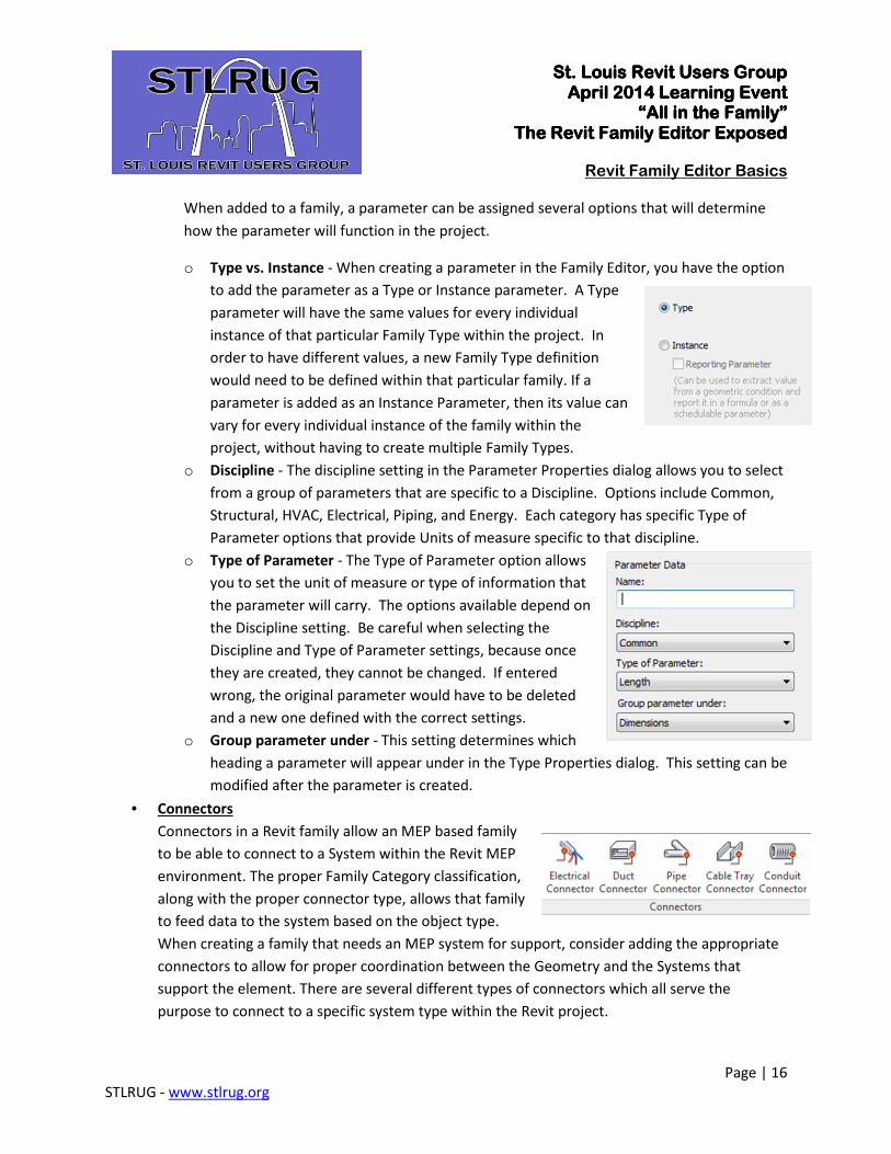
When added to a family, a parameter can be assigned several options that will determine
how the parameter will function in the project.
o Type vs. Instance - When creating a parameter in the Family Editor, you have the option
to add the parameter as a Type or Instance parameter. A Type
parameter will have the same values for every individual
instance of that particular Family Type within the project. In
order to have different values, a new Family Type definition
would need to be defined within that particular family. If a
parameter is added as an Instance Parameter, then its value can
vary for every individual instance of the family within the
project, without having to create multiple Family Types.
o Discipline - The discipline setting in the Parameter Properties dialog allows you to select
from a group of parameters that are specific to a Discipline. Options include Common,
Structural, HVAC, Electrical, Piping, and Energy. Each category has specific Type of
Parameter options that provide Units of measure specific to that discipline.
o Type of Parameter - The Type of Parameter option allows
you to set the unit of measure or type of information that
the parameter will carry. The options available depend on
the Discipline setting. Be careful when selecting the
Discipline and Type of Parameter settings, because once
they are created, they cannot be changed. If entered
wrong, the original parameter would have to be deleted
and a new one defined with the correct settings.
o Group parameter under - This setting determines which
heading a parameter will appear under in the Type Properties dialog. This setting can be
modified after the parameter is created.
• Connectors
Connectors in a Revit family allow an MEP based family
to be able to connect to a System within the Revit MEP
environment. The proper Family Category classification,
along with the proper connector type, allows that family
to feed data to the system based on the object type.
When creating a family that needs an MEP system for support, consider adding the appropriate
connectors to allow for proper coordination between the Geometry and the Systems that
support the element. There are several different types of connectors which all serve the
purpose to connect to a specific system type within the Revit project.
St. Louis Revit Users GroupSt. Louis Revit Users GroupSt. Louis Revit Users GroupSt. Louis Revit Users Group April 2014 Learning EventApril 2014 Learning EventApril 2014 Learning EventApril 2014 Learning Event
“All in the Family”“All in the Family”“All in the Family”“All in the Family” The Revit Family EditorThe Revit Family EditorThe Revit Family EditorThe Revit Family Editor ExposedExposedExposedExposed
Revit Family Editor Basics
Page | 17
STLRUG - www.stlrug.org
o Electrical Connectors - There are numerous types of Electrical connectors available
within the Family Editor. Each allows a specific connection to the available Electrical
Systems, which include: Power (Balanced and Unbalanced), Data, Communication,
Controls, Fire Alarm, Nurse Call, Security and Telephone.
o Duct Connectors - Allow connection to Duct Systems within the project environment.
Available connectors include: Supply Air, Return Air, Exhaust Air, Other Air, Global and
Fitting.
o Pipe Connectors - Allow connections to Piping Systems within the project environment.
Available connectors include: Domestic Hot Water, Domestic Cold Water, Hydronic
Supply, Hydronic Return, Sanitary, Vent, Other, Fire Protection Wet, Fire Protection Dry,
Fire Protection Pre-Action, Fire Protection-Other, Global and Fitting.
o Cable Tray Connectors - Allows a Cable Tray to connect to the loaded family.
o Conduit Connectors - Allows Conduit to connect to the loaded family.
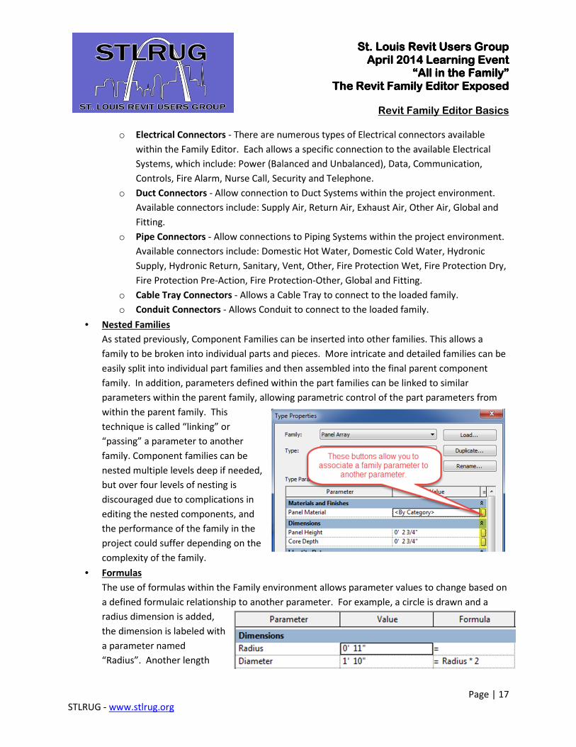
• Nested Families
As stated previously, Component Families can be inserted into other families. This allows a
family to be broken into individual parts and pieces. More intricate and detailed families can be
easily split into individual part families and then assembled into the final parent component
family. In addition, parameters defined within the part families can be linked to similar
parameters within the parent family, allowing parametric control of the part parameters from
within the parent family. This
technique is called “linking” or
“passing” a parameter to another
family. Component families can be
nested multiple levels deep if needed,
but over four levels of nesting is
discouraged due to complications in
editing the nested components, and
the performance of the family in the
project could suffer depending on the
complexity of the family.
• Formulas
The use of formulas within the Family environment allows parameter values to change based on
a defined formulaic relationship to another parameter. For example, a circle is drawn and a
radius dimension is added,
the dimension is labeled with
a parameter named
“Radius”. Another length
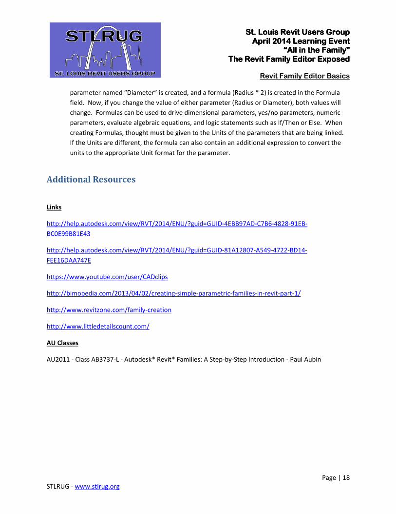
St. Louis Revit Users GroupSt. Louis Revit Users GroupSt. Louis Revit Users GroupSt. Louis Revit Users Group April 2014 Learning EventApril 2014 Learning EventApril 2014 Learning EventApril 2014 Learning Event
“All in the Family”“All in the Family”“All in the Family”“All in the Family” The Revit Family EditorThe Revit Family EditorThe Revit Family EditorThe Revit Family Editor ExposedExposedExposedExposed
Revit Family Editor Basics
Page | 18
STLRUG - www.stlrug.org
parameter named “Diameter” is created, and a formula (Radius * 2) is created in the Formula
field. Now, if you change the value of either parameter (Radius or Diameter), both values will
change. Formulas can be used to drive dimensional parameters, yes/no parameters, numeric
parameters, evaluate algebraic equations, and logic statements such as If/Then or Else. When
creating Formulas, thought must be given to the Units of the parameters that are being linked.
If the Units are different, the formula can also contain an additional expression to convert the
units to the appropriate Unit format for the parameter.
Additional Resources
Links
http://help.autodesk.com/view/RVT/2014/ENU/?guid=GUID-4EBB97AD-C7B6-4828-91EB-
BC0E99B81E43
http://help.autodesk.com/view/RVT/2014/ENU/?guid=GUID-81A12807-A549-4722-BD14-
FEE16DAA747E
https://www.youtube.com/user/CADclips
http://bimopedia.com/2013/04/02/creating-simple-parametric-families-in-revit-part-1/
http://www.revitzone.com/family-creation
http://www.littledetailscount.com/
AU Classes
AU2011 - Class AB3737-L - Autodesk® Revit® Families: A Step-by-Step Introduction - Paul Aubin