Embed Size (px)
Citation preview

Illustrated Guide for Building a Switch (Turnout)
by curt young (spring 2015) version 1.0
CEO El Cheapo Switch Co.
Introduction
Disclaimer: Many people use the term “switch” or “turnout” interchangeably. I have traditionally used the term switch as I have never heard anyone refer to a “turnout yard”, but am warming to the term turnout as it is becoming more common usage. Officially, the switch is the moving portion of a turnout. The track crew installs a turnout. The operating crew throws the switch to change the train's route. You don't "throw the turnout" because the whole turnout does not move, only the switch portion of the turnout moves.
I have built 12 turnouts so far. The first one I built was a dual radius version of 50 and 42 foot radius. It was complicated and turned out to be almost 30 feet long. Stick with turnouts that have a straight section and a curved section if you can. This is the first time I have published this paper, although it has gone through many revisions. The main purpose of this paper is to give the builder a good road map on how to build a turnout, so they do not have to start with nearly a blank sheet of paper as I did. When you read through these instructions they seem impossibly complex. Part of this is the fault of my writing skills, but the other part is that I have included detailed steps making it seem more complex, but it will fall into place once you start. Figure the first turnout will take at least 40 hours of labor, not counting machining the points and rail, and building the jigs. It gets easier after this. Mariposa Live Steamers claims if all the parts are cut they can assemble one in 4 hours, but they have assembled over 300 turnouts.
Building a turnout is not a overly complicated affair, but involves a lot of steps, and does require some attention to detail to get it gauged properly. The major consideration one needs is access to a milling machine as there are a number of operations that require one. A 44 inch table will allow a 24 inch long cut for points and the foot without having to reset the work. Depending on turnout radius, plan on 12 to 16 feet of length for completed turnout.
It appears that everyone has the “best” turnout design, as there are many varieties. To keep this tradition going my design is a combination of Train Mountain Railroad Museum, Kitsap Live Steamers (thanks to Jerry Crane) and Mariposa Live Steamers. I will be using scale aluminum rail for the turnout, but at end of article I will give steps for those making switches with strap iron, the main difference being the slotted ties. This article is written with a lot of steps and details so even a beginner should be able to follow, but the more experienced builder will also benefit. The instructions jump around a bit as this is a one person operation and I am still learning as I go along. If you want to machine all the parts first that would be helpful if it is a team assembly effort.
I originally started using tie plates and that required spacers under the frog and the switch points to
Page 1
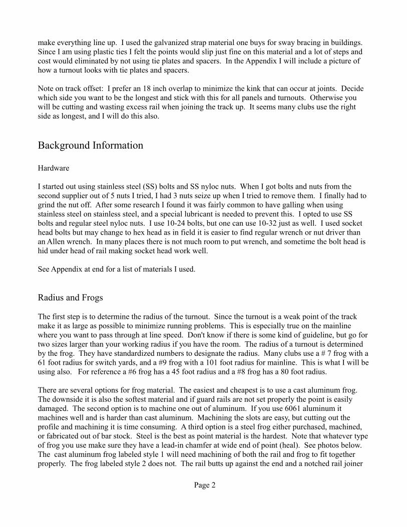
make everything line up. I used the galvanized strap material one buys for sway bracing in buildings. Since I am using plastic ties I felt the points would slip just fine on this material and a lot of steps and cost would eliminated by not using tie plates and spacers. In the Appendix I will include a picture of how a turnout looks with tie plates and spacers.
Note on track offset: I prefer an 18 inch overlap to minimize the kink that can occur at joints. Decide which side you want to be the longest and stick with this for all panels and turnouts. Otherwise you will be cutting and wasting excess rail when joining the track up. It seems many clubs use the right side as longest, and I will do this also.
Background Information
Hardware
I started out using stainless steel (SS) bolts and SS nyloc nuts. When I got bolts and nuts from the second supplier out of 5 nuts I tried, I had 3 nuts seize up when I tried to remove them. I finally had to grind the nut off. After some research I found it was fairly common to have galling when using stainless steel on stainless steel, and a special lubricant is needed to prevent this. I opted to use SS bolts and regular steel nyloc nuts. I use 10-24 bolts, but one can use 10-32 just as well. I used socket head bolts but may change to hex head as in field it is easier to find regular wrench or nut driver than an Allen wrench. In many places there is not much room to put wrench, and sometime the bolt head is hid under head of rail making socket head work well.
See Appendix at end for a list of materials I used.
Radius and Frogs
The first step is to determine the radius of the turnout. Since the turnout is a weak point of the track make it as large as possible to minimize running problems. This is especially true on the mainline where you want to pass through at line speed. Don't know if there is some kind of guideline, but go for two sizes larger than your working radius if you have the room. The radius of a turnout is determined by the frog. They have standardized numbers to designate the radius. Many clubs use a # 7 frog with a 61 foot radius for switch yards, and a #9 frog with a 101 foot radius for mainline. This is what I will be using also. For reference a #6 frog has a 45 foot radius and a #8 frog has a 80 foot radius.
There are several options for frog material. The easiest and cheapest is to use a cast aluminum frog. The downside it is also the softest material and if guard rails are not set properly the point is easily damaged. The second option is to machine one out of aluminum. If you use 6061 aluminum it machines well and is harder than cast aluminum. Machining the slots are easy, but cutting out the profile and machining it is time consuming. A third option is a steel frog either purchased, machined, or fabricated out of bar stock. Steel is the best as point material is the hardest. Note that whatever type of frog you use make sure they have a lead-in chamfer at wide end of point (heal). See photos below. The cast aluminum frog labeled style 1 will need machining of both the rail and frog to fit together properly. The frog labeled style 2 does not. The rail butts up against the end and a notched rail joiner
Page 2
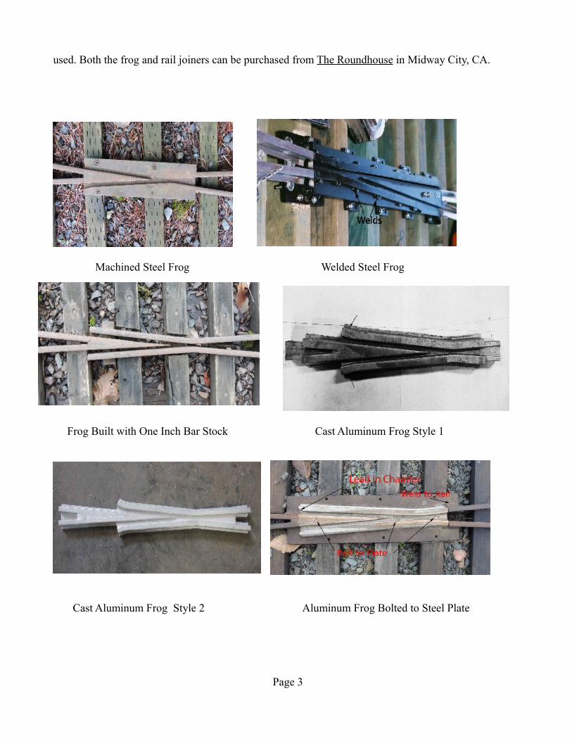
used. Both the frog and rail joiners can be purchased from The Roundhouse in Midway City, CA.
Machined Steel Frog Welded Steel Frog
Frog Built with One Inch Bar Stock Cast Aluminum Frog Style 1
Cast Aluminum Frog Style 2 Aluminum Frog Bolted to Steel Plate
Page 3
The placement of the frog appears NOT to be critical. One would think that it should be located at the intersection of the straight and curved lines if the entire turnout was drawn out. Calculated out for a # 7 frog, of 61 foot radius, the point of the frog would be 103 inches from the end of the points. At the proper calculated distance the angle is so flat the points are tight against the rail, so there is no room for connectors. For a #7 frog Train Mountain uses 76 inches and Mariposa uses 66 inches for distance from points to neck of frog. To me seems the further back from the points the better, so I am using 86 inches from the points to the neck of the frog. For the 101 foot radius of #9 frog the calculated distance is 135 inches. TM uses 109 inches and Mariposa uses 88 inches. I am using 109 inches. Slight adjustments in the location of the frog may be needed as I prefer the rail ends to be supported by a tie.
Radius Board or Guide
Once you settle on the desired radius you have two options to lay out the turnout. One is to get a 1:1 engineering print made of the turnout. The other option is to construct a radius board or guide to bend the rail properly. This is covered in detail in another article on http://gncrailway.com under articles - “How to Build a Radius Guide”, and is the option I use.
Ties
A true 1/8 scale tie would be 12 inches long. However this does not give much side stability, especially for Narrow Gauge equipment. Most use 15-16 inch ties, whichever gives you the least amount of waste when cutting. Commercial ties are 16 inches. The ties for a turnout vary in length from 16 to 30 inches, with the two for mounting the switch stand up to 40 inches long. The length of these two ties depends on what you are going to hang on the end to control switch points. If you have a large upright switch stand you need enough room to easily pass by without hitting your knee or feet. At least 21 inches from outer rail to obstruction is recommended. You can always shorten these two ties if length is not needed.
Depending on budget and time, ties can be made of wood, plastic composite, or cement. Wood can be free if you scrounge the local construction sites. The cheapest locally available plastic composite material I found was 1.5 inch square Trex baluster material. It comes in 36 in. length so there is some waste from cutting to the various lengths. The standard tie material of 2x2 plastic in 8 foot lengths is considerably more expensive. If you have major frost heave problems, or use just clean ballast, you should consider using 3.5 x 2 inch ties. The deeper ties hold the rail in place better with the ball bearing like material of clean 3/8 or 5/8 ballast. The clean ballast holds less water reducing frost heave problems, if the sub-ballast can drain.
Points
Points are a set of linked tapering rails at the narrow end of the turnout. Moving the points determines on which track the train travels. Assuming you are using scale rail you can make the points out of steel scale rail or strap iron. Using aluminum is not recommended as it is far too soft when ends are
Page 4
machined down to 50-60 thousands on an inch. Machining points out of scale steel rail is more involved than using strap iron as you have to machine both sides. Being El Cheapo I used 1 x 3/8 inch strap iron. You can use 1 x 1/2 steel to match the rail head, but there is more machining to do and there is a larger machined shelf at the narrow tip. For a 60 foot radius turnout I cut my material to 30 inches. For 101 foot radius I use 36 inches. Any less length and you will not have room to bolt point to rail. You can make them longer, but you will need more spacer bars to maintain gauge. Before you start assembling figure out how you will attach the point to the rail. Strap iron to scale rail will require some adapter, more on this later. Another option is to weld a short piece of scale steel rail to the point, and then you will have a perfect match up to the scale aluminum rail.
Jigs and Gauges
You will need a jig to hold the point material for machining, and also one to cut the inset into the rail. You will also need to build several gauges to gauge the track and frog. To make this document flow better these will be addressed in the Appendix at the end.
Machining OperationsMachining Points
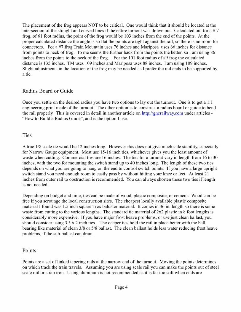
Below is a picture of the machining setup for points assuming you are using strap iron.
Setup for Machining Points
As you can see in picture I used a 2x2 thick wall tube to serve as a flat stable surface to clamp the point material to. The tube is anchored to the table at an angle so that the machined portion tapers from 55 thousands of material to nothing in about 20-22 inches. To get this angle I took two pieces of aluminum machined to fit in the table slot, with a 3/8 inch overhang on one side. For the setup above the 3/8 overhang is on left side and the flush side is on the right. You can adjust the angle by sliding the block a little one way or another. If you have more than one turnout to build, machine all the left hand points, then change setup to machine the right hand points. A solid carbide cutter costs more but
Page 5
you can run at higher speed and lasts 5X longer than HSS. I found a 1/2 inch cutter running at 1500 rpm with a feed rate of one rotation (.200) every 3 seconds worked well. You can machine a point in about 15 - 20 minutes.
A note on the setup. One can measure from the edge of the mill table to the support tube. In 20 inches it should change from 0 to 0.0320 inches. Being measured challenged I still run the table back and forth with an indicator in it to see if it changes from .055 to .375 inches in 20-22 inches.
It is important to clamp the point material about every 8 inches to keep point flat against the guide. One can use a length of 1/4 material underneath the point material to elevate it so cutter will pass over the foot on the end clamp.
Once the point is machined grind or file a radius on the inside of rail, but be careful in zone where it is very thin. File the sharp corner of the point down and one can even bevel the end slightly to minimize splinting the points with leading truck.
Machining Inside and Outside Rails
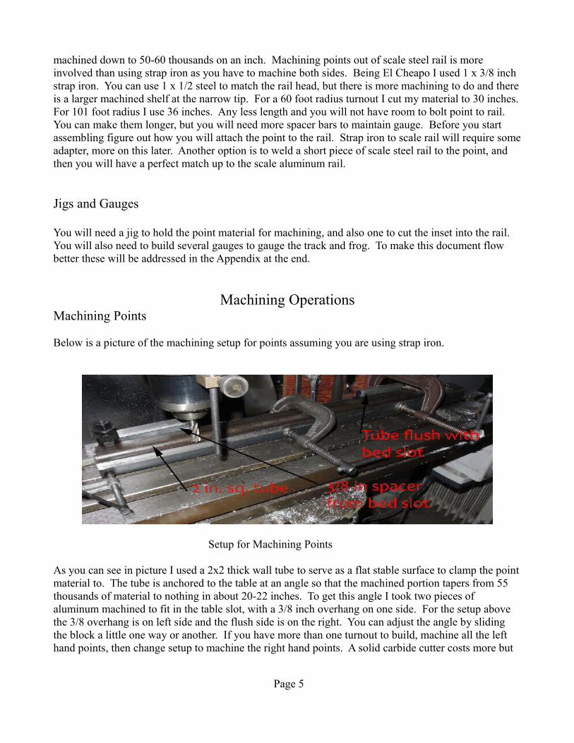
To fit the points flush with the rail an inset has to be milled into the rail at a 1% angle. See the Appendix on how I built my jig. If the angle is correct the cut on the head will be about 6 inches long and the cut on the foot about 21 inches long. See also picture on page 8.
Since the end of the point is 55 thousands thin, make the inset cut on the side of the head 20 thousands deeper, in this case 0.075 inch. The cut on the foot should be another 0.030 deeper than the head depth, or 0.105 inches. This deeper cut should prevent the point from hitting the rail foot before it hits the head. Note: vibration can be a problem in machining the rail foot, so watch clamps as they can loosen, and do not space clamps too far apart. Galling can also be a problem with aluminum so watch cutter closely and use kerosene, paraffin, or some other light lubricant if necessary. For a right hand turnout with the left rail (straight) the cut starts 6 inches from the end, and on the right rail (curved) it starts at 24 inches, assuming an 18 inch offset for rails with right side being longest.
Setup for Milling Inset in Rail
Page 6
Construction
Assemble Ties
The two 36 inch ties are for the switch stand. These can be longer or shorter depending on what type of control mechanism you have. It the stand is tall make sure you have at least 21 inches between outside rail and stand so rider's knees do not hit. My material is 36 inches long, but many use 40 inches for the two switch stand ties. It is somewhat of a standard to have 3.5 inches from rail head to end of ties. With the straight rail this has already been fixed. On the curved side of the turnout as you go from narrow end to wide end I increase the length in one or two inch increments to keep the end of tie distance roughly between 3 and 4 inches from the rail head.
Place the ties of correct length in the turnout jig. For a 60' radius turnout I used ties lengths: 2 (36 in.), 8 (16 in.), 4 (17 in.), 5 (18 in.), 4 (20 in.), 4 (22in.), 5 (24 in.), 4 (26 in.), 2 (28 in.)
For a 102' radius turnout I used: 2(36”), 9(16”) 5(17”), 7(18”), 5(19”), 4(20”), 6(22”), 4(24”), 3(25”), 2(26”).
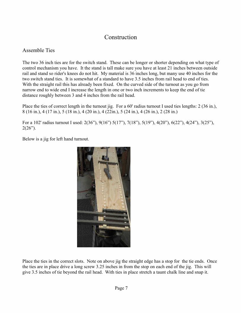
Below is a jig for left hand turnout.
Place the ties in the correct slots. Note on above jig the straight edge has a stop for the tie ends. Once the ties are in place drive a long screw 3.25 inches in from the stop on each end of the jig. This will give 3.5 inches of tie beyond the rail head. With ties in place stretch a taunt chalk line and snap it.
Page 7
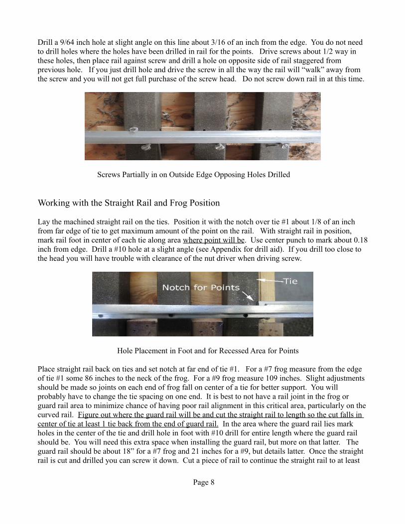
Drill a 9/64 inch hole at slight angle on this line about 3/16 of an inch from the edge. You do not need to drill holes where the holes have been drilled in rail for the points. Drive screws about 1/2 way in these holes, then place rail against screw and drill a hole on opposite side of rail staggered from previous hole. If you just drill hole and drive the screw in all the way the rail will “walk” away from the screw and you will not get full purchase of the screw head. Do not screw down rail in at this time.
Screws Partially in on Outside Edge Opposing Holes Drilled
Working with the Straight Rail and Frog Position
Lay the machined straight rail on the ties. Position it with the notch over tie #1 about 1/8 of an inch from far edge of tie to get maximum amount of the point on the rail. With straight rail in position, mark rail foot in center of each tie along area where point will be. Use center punch to mark about 0.18 inch from edge. Drill a #10 hole at a slight angle (see Appendix for drill aid). If you drill too close to the head you will have trouble with clearance of the nut driver when driving screw.
Hole Placement in Foot and for Recessed Area for Points
Place straight rail back on ties and set notch at far end of tie #1. For a #7 frog measure from the edge of tie #1 some 86 inches to the neck of the frog. For a #9 frog measure 109 inches. Slight adjustments should be made so joints on each end of frog fall on center of a tie for better support. You will probably have to change the tie spacing on one end. It is best to not have a rail joint in the frog or guard rail area to minimize chance of having poor rail alignment in this critical area, particularly on the curved rail. Figure out where the guard rail will be and cut the straight rail to length so the cut falls in center of tie at least 1 tie back from the end of guard rail. In the area where the guard rail lies mark holes in the center of the tie and drill hole in foot with #10 drill for entire length where the guard rail should be. You will need this extra space when installing the guard rail, but more on that latter. The guard rail should be about 18” for a #7 frog and 21 inches for a #9, but details latter. Once the straight rail is cut and drilled you can screw it down. Cut a piece of rail to continue the straight rail to at least
Page 8
18 inches beyond the end of frog. I like to use 2 rail joiners to bolt the two sections together. Two pieces of 3x1/2x1/8 inch pieces of aluminum works well.
Once all the straight rail is screwed to ties make sure it is straight. Stretch a line from one end to the other. Then adjust for any warbles by gently tapping the end of the ties until rail is parallel to string. I have found that the board screwed along edge can be a problem with these adjustments. I took the board off from about the frog to the wide end so I can tap the rail straight. Next I C-clamp a 1 inch square tube to the outside of rail to keep it in place while working on turnout.
Place Frog and Measure the 4 Rails Attached to Frog
Lay points in position. With frog in position measure and cut rail from frog to end heal end of points. Leave yourself some wiggle room and cut an inch longer, you can trim to fit later. Next measure and cut rails that attach to far end of frog, leave at least 18 inches beyond end of frog. You can leave longer, it but may be awkward to handle completed turnout. Have end of rails end in middle of a tie for best strength. On all 4 rails mark which side and end you want to machine or drill to connect to frog.
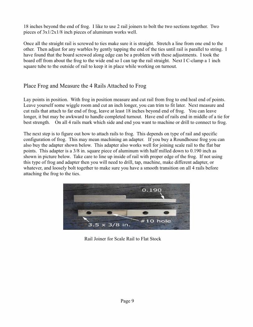
The next step is to figure out how to attach rails to frog. This depends on type of rail and specific configuration of frog. This may mean machining an adapter. If you buy a Roundhouse frog you can also buy the adapter shown below. This adapter also works well for joining scale rail to the flat bar points. This adapter is a 3/8 in. square piece of aluminum with half milled down to 0.190 inch as shown in picture below. Take care to line up inside of rail with proper edge of the frog. If not using this type of frog and adapter then you will need to drill, tap, machine, make different adapter, or whatever, and loosely bolt together to make sure you have a smooth transition on all 4 rails before attaching the frog to the ties.
Rail Joiner for Scale Rail to Flat Stock
Page 9
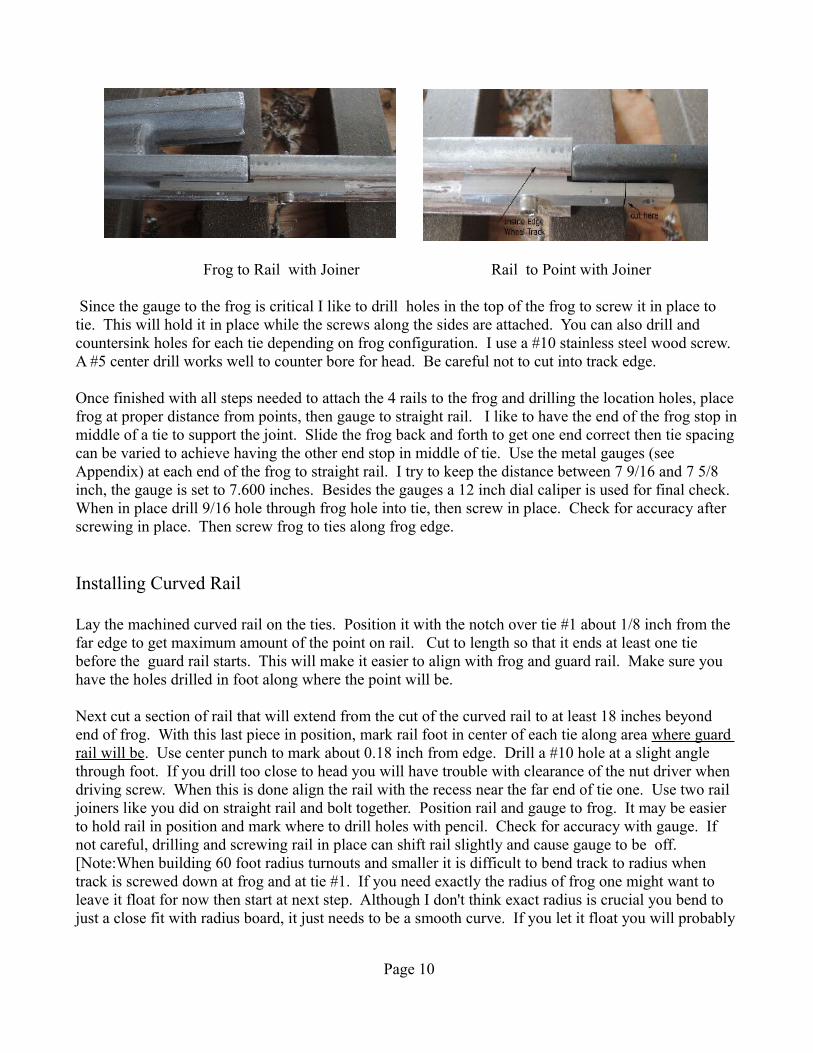
Frog to Rail with Joiner Rail to Point with Joiner
Since the gauge to the frog is critical I like to drill holes in the top of the frog to screw it in place to tie. This will hold it in place while the screws along the sides are attached. You can also drill and countersink holes for each tie depending on frog configuration. I use a #10 stainless steel wood screw. A #5 center drill works well to counter bore for head. Be careful not to cut into track edge.
Once finished with all steps needed to attach the 4 rails to the frog and drilling the location holes, place frog at proper distance from points, then gauge to straight rail. I like to have the end of the frog stop in middle of a tie to support the joint. Slide the frog back and forth to get one end correct then tie spacing can be varied to achieve having the other end stop in middle of tie. Use the metal gauges (see Appendix) at each end of the frog to straight rail. I try to keep the distance between 7 9/16 and 7 5/8 inch, the gauge is set to 7.600 inches. Besides the gauges a 12 inch dial caliper is used for final check. When in place drill 9/16 hole through frog hole into tie, then screw in place. Check for accuracy after screwing in place. Then screw frog to ties along frog edge.
Installing Curved Rail
Lay the machined curved rail on the ties. Position it with the notch over tie #1 about 1/8 inch from the far edge to get maximum amount of the point on rail. Cut to length so that it ends at least one tie before the guard rail starts. This will make it easier to align with frog and guard rail. Make sure you have the holes drilled in foot along where the point will be.
Next cut a section of rail that will extend from the cut of the curved rail to at least 18 inches beyond end of frog. With this last piece in position, mark rail foot in center of each tie along area where guard rail will be. Use center punch to mark about 0.18 inch from edge. Drill a #10 hole at a slight angle through foot. If you drill too close to head you will have trouble with clearance of the nut driver when driving screw. When this is done align the rail with the recess near the far end of tie one. Use two rail joiners like you did on straight rail and bolt together. Position rail and gauge to frog. It may be easier to hold rail in position and mark where to drill holes with pencil. Check for accuracy with gauge. If not careful, drilling and screwing rail in place can shift rail slightly and cause gauge to be off. [Note:When building 60 foot radius turnouts and smaller it is difficult to bend track to radius when track is screwed down at frog and at tie #1. If you need exactly the radius of frog one might want to leave it float for now then start at next step. Although I don't think exact radius is crucial you bend to just a close fit with radius board, it just needs to be a smooth curve. If you let it float you will probably
Page 10

need at least one other person to hold radius and set gauge at same time.]
Now go back to tie #1 to set the gauge for curved rail. First step will be to gauge and screw in a tie in the straight section beyond the recess (beyond tie #1), as when you bow the rail for the radius this area will narrow and you want it to stay parallel to the straight rail. Next place gauge right before the notch and drill and screw down rail to tie #1. The next step can take some patience, and an extra set of hands helps. Use the radius gauge bend the rail into position (see my article on gncrailway.com website for building it). With rail pushed in place mark the ties for drill location. Take the board away and drill matching hole on other side of tie. If not 100% sure of the process do this about every 18 inches and screw rail down to see how it fits. Sight along it from a distance and see how it looks. It does not have to be perfect fit to radius board, and the area where frog is will be straight, but when you sight down rail it should be a smooth curve (unless you need a very tight fit for your track). Since the matching rail is gauged to the outside rail the exact radius is immaterial.
Installing Guard Rails
Cut two pieces of 18 inch rail for a #7 frog or 21 inches for a #9 frog. The inside foot has to be cut off to allow close spacing to the rail. To make it easier to machine off I first cut the excess with a band saw. Then put in mill and machine down the foot to just above the rib. Next put 1.5 inches of the end in vise, and bend each end 11 degrees away from milled foot. Next cut spacers 5/8 inch long out of brass tubing. Needs to pass a 10-24 bolt, so 1/4 inch diameter tube is good. For best results use a set of trucks to obtain the proper spacing. Hold the truck wheels tight against the guard rail and make sure it does not hit the point of the frog as you move it through the frog. Use a fine wheel on a grinder to machine tubing to correct length to achieve this.
Guard Rail Ready to Install Guard Rail Installed
Gauging Inside Track
Figure out the attachment method from the inside rails to the point. You can use the joiner shown on page 10. Mark and drill holes in rail for joiner. I prefer to have 2 holes to attach joiner to rail, and one to attach joiner to point to allow more lateral movement of the point. Therefore, for the narrow end that attaches to point cut one hole off. Attach the joiner to scale rail. Do not drill connecting hole for point at this stage. See picture on page 10.
Page 11

Next lay the points in position, and leave about 0.100 inch from end of point to recess in rail to allow for heat expansion. Cut the curved and straight sections of rail from the frog to points to length. You may have to adjust tie spacing so the joints lie in middle of tie. Gauge these tracks from the matching outer rail. You will need to use the gauges with notches cut out to span over top of rail, see gauges in Appendix. Use at least 2 gauges and screw down rail between gauges. As you have probably noticed you need to drill and start screw on one side then drill and set screw on opposite side. Then seat first screw. If you seat first screw without the opposite side locked in place, the track will move away from screw and you will loose the correct gauge.
Installing Points
If you are going to install a nylon strip for the points to rest on this is the next step. I used 0.125 inch thick acetal nylon and milled a slot in tie 0.110 inches deep. This sets the points 15 thousands above the ties at the front end, reducing friction. You can use two 4 inch strips or one 12 inch strip for this. Note: you can get a 12 x 12 inch sheet from Enco for $7.50.
The points need to be adjusted so the straight one is straight and the other one is curved to the proper radius. Take the straight one and lay a 3 foot straight edge along the milled portion of point. You will see divergence starting where the cut ends. Put the point in vise at the end of cut and bend slightly towards milled side. You want to end up with a straight line from the thin end of the machined portion to the end of the point. In other words a straight line where the wheels travel. Bending is tricky as it is hard to bend until you break the “skin” then it moves much easier, usually meaning you bent it too far.
Next do similar for the curved point. Use a marker and draw a line every 7 inches or so. This will help when you have to correct your bend. Put the point in the vise at marked lines and bend slightly. Lay the machined portion of the point so it fits on top edge of radius guide, and adjust bend so it follows the curve of board. Remember it is not the point itself, just the line traveled by the wheel. Point should be bent towards the machined portion of point.
Lay the points in position on ties and see it there are any ties that are too high (point rocks). If so gently grind the tie(s) so the point lies flat against all the ties. If you use the nylon rub strip the first few ties should have a few thousands of clearance.
The next step is to place the straight point in place which goes from the gauged straight rail to the recess in the curved rail. At the beginning of point you should have no more than 2 inches flush against the rail, and there should be no space between the side of the point and the side of recessed rail. Many points need to be bent just slightly at the tip to make this happen. Do the same steps for the curved point.
Once points fit well lay the point in position and leave about 0.10 inches between point and recess notch to allow for heat expansion. Mark the point on center between tie #1 and #2, then again about 10 inches away. These positions will be where you place the angle brackets to hold the spreaders. Make them out of 3/4 inch angle iron or 3/4 by 1 inch is even better. I mark them 3/4 inch wide and I drill a 1/4 inch hole in one leg near the bend, then cut in pieces. I weld them in place, but they could be
Page 12
bolted. I space the angle bracket below the bottom of point by at least 0.060 so the spreader bar does not to rub on the bottom of rail. If your points are longer than 36 inches additional spreader bars will be necessary.
Again put the points back in position leaving 0.10 inches gap at the end. Make sure the bottom of point is flush against the rail and aligns with top of aluminum rail. Mark and drill hole in point where joiner fits. See picture on page 10. This hole should not be a tight fit as the bolt should have some wiggle room. You want the point to move freely back and forth from against the rail to open a half inch. If it does not, enlarge the hole slightly, and/or bend the joiner to allow free movement. If you want to paint the points now is the time before you bolt it to joiner.
Installing Control Mechanism and Spreader Bars
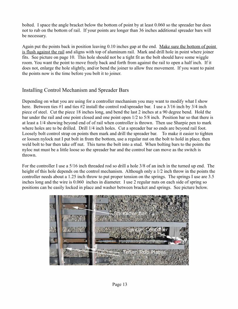
Depending on what you are using for a controller mechanism you may want to modify what I show here. Between ties #1 and ties #2 install the control rod/spreader bar. I use a 3/16 inch by 3/4 inch piece of steel. Cut the piece 18 inches long, and bend the last 2 inches at a 90 degree bend. Hold the bar under the rail and one point closed and one point open 1/2 to 5/8 inch. Position bar so that there is at least a 1/4 showing beyond end of of rail when controller is thrown. Then use Sharpie pen to mark where holes are to be drilled. Drill 1/4 inch holes. Cut a spreader bar so ends are beyond rail foot. Loosely bolt control strap on points then mark and drill the spreader bar. To make it easier to tighten or loosen nylock nut I put bolt in from the bottom, use a regular nut on the bolt to hold in place, then weld bolt to bar then take off nut. This turns the bolt into a stud. When bolting bars to the points the nyloc nut must be a little loose so the spreader bar and the control bar can move as the switch is thrown.
For the controller I use a 5/16 inch threaded rod so drill a hole 3/8 of an inch in the turned up end. The height of this hole depends on the control mechanism. Although only a 1/2 inch throw in the points the controller needs about a 1.25 inch throw to put proper tension on the springs. The springs I use are 3.5 inches long and the wire is 0.060 inches in diameter. I use 2 regular nuts on each side of spring so positions can be easily locked in place and washer between bracket and springs. See picture below.
Page 13

Assuming you are using a spring loaded switch the adjustment of spring tension for both switch positions is needed. Fully throw switch in one direction, then adjust spring tension so the point is tight against the rail and when you squeeze and release the rail to change to the other position there is some spring tension, but not too much. See note in Appendix under Misc. notes if point is wobbly. You want enough spring tension so the point springs back firmly against the rail, but not enough spring tension where it will derail a light car when when going against the current position. Adjust the other position in the same manner, then lock down the adjusting nuts. For controller see materials list in Appendix.
It is not necessary to have a spring actuated points, but it makes it so much nicer when running. If you have a straight throw switch you will have to manually throw the switch if it is positioned for the opposite direction and you are entering from the backside of turnout. If you do not align the switch for your run direction you will derail engine and cars when going against the current position.
Rather than a controller you can make a “kick” switch which many tracks use in switch yards. Once the points are moved past the middle the spring forces them over to the other position. If you want to make a “kick” switch see photo below.
To improve on this make the bar slider longer, bend up the ends an inch. Then brakeman can kick this rather than getting their foot into the switch itself.
Now the turnout and switch should be finished. Gently pry it out of the jig. It is safer and easier to carry vertically. Caution helpers do NOT carry by the all too inviting end rails for they bend as turnout is quite heavy. When in the field do not drag turnout as you can wreck the alignment of the rails.
Page 14
Misc. Notes.
1. I am considering screwing boards on top of the ties on each side of rails to hold everything in place during transport. In some cases by time turnout is in place on track the straight rail is not straight anymore, especially in the points area.
2. Because the foot is machined 30 deeper than head if the bolt holding the points to the rail and the bolts holding the spreader bars to the rail are too loose the point will twist, or wobble, when point pressed against the head. This gap increases the risk of splitting the points. Also, the bolt holding the points to the rail should not be too loose as this will increase the wobble effect also.
3. Switch lubrication. Do not use grease on sliding surface with points. Grease attracts dirt and rock chips. Use something that will last awhile and is not sticky, like spray on dry film graphite. A product like WD 40 is a good lubricant but it evaporates.
Page 15
Appendix
Points Jigs
On page 5 there is a picture of the setup for machining the points. I described this fairly well so will not go over it again.
Recessed Rail Jig
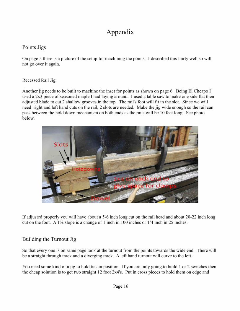
Another jig needs to be built to machine the inset for points as shown on page 6. Being El Cheapo I used a 2x3 piece of seasoned maple I had laying around. I used a table saw to make one side flat then adjusted blade to cut 2 shallow grooves in the top. The rail's foot will fit in the slot. Since we will need right and left hand cuts on the rail, 2 slots are needed. Make the jig wide enough so the rail can pass between the hold down mechanism on both ends as the rails will be 10 feet long. See photo below.
If adjusted properly you will have about a 5-6 inch long cut on the rail head and about 20-22 inch long cut on the foot. A 1% slope is a change of 1 inch in 100 inches or 1/4 inch in 25 inches.
Building the Turnout Jig
So that every one is on same page look at the turnout from the points towards the wide end. There will be a straight through track and a diverging track. A left hand turnout will curve to the left.
You need some kind of a jig to hold ties in position. If you are only going to build 1 or 2 switches then the cheap solution is to get two straight 12 foot 2x4's. Put in cross pieces to hold them on edge and
Page 16

have one end about 14 inches wide and the other end about 22 inches. Use finish nails to serve as guides to hold ties in place. Sloppy fit is good as makes it easier to lift out finished turnout. If you are going to build numerous turnouts a jig made with 3/4 inch plywood and spacer blocks is much better and gives you some place to set tools. If you buy 2 sheets of 3/4 inch plywood, cut one in half and the other sheet at an angle. The will give you two 48x48 inch and two 18x30x96 inch pieces. With this you can build right and left hand versions. Nail a board on the straight edge to serve as stop for ties. For spacers I used 1.25 inch lengths of 1x2 finished lumber, nailed in with a 3/16 inch shim to give some room for easy removal of finished product. Below is picture of left hand jig, and start of putting in ties.
Page 17
Building Track Gauges
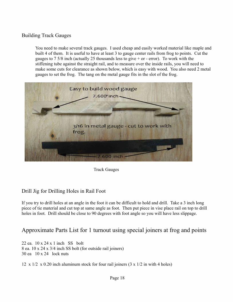
You need to make several track gauges. I used cheap and easily worked material like maple and built 4 of them. It is useful to have at least 3 to gauge center rails from frog to points. Cut the gauges to 7 5/8 inch (actually 25 thousands less to give + or - error). To work with the stiffening tube against the straight rail, and to measure over the inside rails, you will need to make some cuts for clearance as shown below, which is easy with wood. You also need 2 metal gauges to set the frog. The tang on the metal gauge fits in the slot of the frog.
Track Gauges
Drill Jig for Drilling Holes in Rail Foot
If you try to drill holes at an angle in the foot it can be difficult to hold and drill. Take a 3 inch long piece of tie material and cut top at same angle as foot. Then put piece in vise place rail on top to drill holes in foot. Drill should be close to 90 degrees with foot angle so you will have less slippage.
Approximate Parts List for 1 turnout using special joiners at frog and points
22 ea. 10 x 24 x 1 inch SS bolt8 ea. 10 x 24 x 3/4 inch SS bolt (for outside rail joiners)30 ea 10 x 24 lock nuts
12 x 1/2 x 0.20 inch aluminum stock for four rail joiners (3 x 1/2 in with 4 holes)
Page 18

10 scale rail to flat stock joiners - shown on page 9 2ea 1.5 x 4 x 1/8 inch Teflon strip8 ea. brass wood screws 6 x 3/4 pan head to screw down 1/8 in. Teflon strip1/4 inch diameter brass or aluminum tube
5/16 -18 by 18 in. zinc plated threaded rod5 ea. 5/16 -18 nuts SS2 ea. washers SS1ea. push-pull toggle clamp, zinc plated steel, 1.25 inch throw, 5/16 x 18 thread (#605 or #609 from The Toggle Clamp Store for $8 and $10). Built for indoor machine tool work the tolerance of the piston is too close for our needs and any corrosion or grime will make it unusable. Take out piston and drill hole larger to give at least 25 thousands of clearance.
2 ea. springs 3.5 inches long with 0.060 diameter wire
4 ea 1/4 x 20 x 5/8 in. long bolts 4 ea 1/4 x 20 nyloc SS nuts
350 ea stainless steel screws - 10x1 slot hex washer head SMS from MPT Fastener Corp pg. 18
#10 and 9/64 inch drills #5 center drill1/2 inch carbide cutter3/8 inch HSS cuttermisc. C clamps12 inch dial caliper
Building a Turnout with Tie Plates and Spacers
Screw and Tie Plate
Page 19
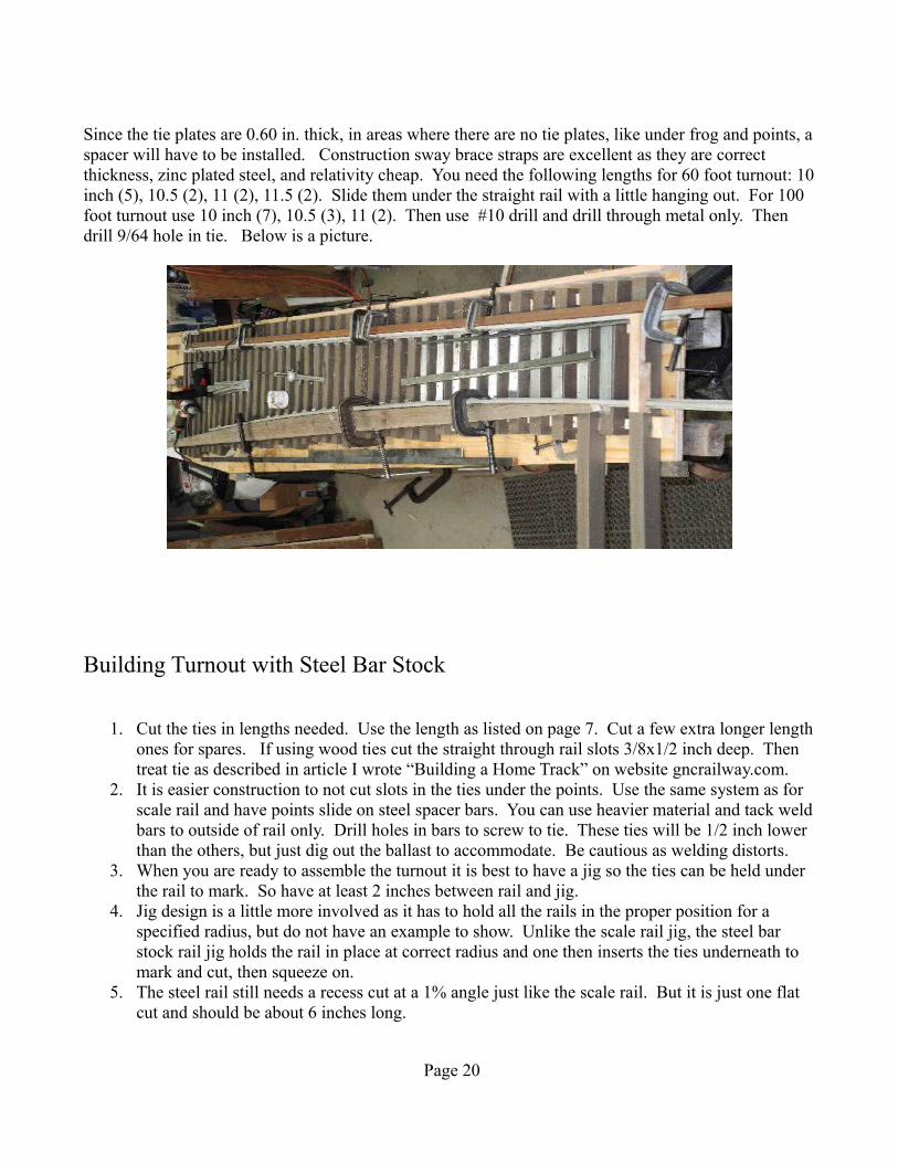
Since the tie plates are 0.60 in. thick, in areas where there are no tie plates, like under frog and points, a spacer will have to be installed. Construction sway brace straps are excellent as they are correct thickness, zinc plated steel, and relativity cheap. You need the following lengths for 60 foot turnout: 10 inch (5), 10.5 (2), 11 (2), 11.5 (2). Slide them under the straight rail with a little hanging out. For 100 foot turnout use 10 inch (7), 10.5 (3), 11 (2). Then use #10 drill and drill through metal only. Then drill 9/64 hole in tie. Below is a picture.
Building Turnout with Steel Bar Stock
1. Cut the ties in lengths needed. Use the length as listed on page 7. Cut a few extra longer length ones for spares. If using wood ties cut the straight through rail slots 3/8x1/2 inch deep. Then treat tie as described in article I wrote “Building a Home Track” on website gncrailway.com.
2. It is easier construction to not cut slots in the ties under the points. Use the same system as for scale rail and have points slide on steel spacer bars. You can use heavier material and tack weld bars to outside of rail only. Drill holes in bars to screw to tie. These ties will be 1/2 inch lower than the others, but just dig out the ballast to accommodate. Be cautious as welding distorts.
3. When you are ready to assemble the turnout it is best to have a jig so the ties can be held under the rail to mark. So have at least 2 inches between rail and jig.
4. Jig design is a little more involved as it has to hold all the rails in the proper position for a specified radius, but do not have an example to show. Unlike the scale rail jig, the steel bar stock rail jig holds the rail in place at correct radius and one then inserts the ties underneath to mark and cut, then squeeze on.
5. The steel rail still needs a recess cut at a 1% angle just like the scale rail. But it is just one flat cut and should be about 6 inches long.
Page 20

6. Once the jig is holding all the rails with the frog positioned and attached one can start attaching ties. Start at the points, place gauge between rails then weld the bars to the rail at correct spacing - on outside edge of rail only. Be cautious as welding distorts.
7. After the steel bars under the points are welded in move to the next space and slide a tie under the rails to line up with the straight rail slots. Mark the angle slots with a scribe then take to milling machine and with 3/8 router cut the slot. One needs a vice that swivels for this operation. After first slot is cut move over 7 5/8 in. and cut second slot. A digital readout is great for this, but allow for diameter of cutter as the 7 5/8 dimension is between inside edge of the slots. Do the same operation for rest of ties. The angle will change slightly as you move away from points.
8. The best way to get ties pressed on to rail is to use a heavy bar on top of rail, a lighter bar on bottom, and then use two C clamps to squeeze the tie into place. The tie must be lined up perfectly with all 4 slots or you will crush the slot and ruin tie.
9. When you get to the frog you will have to machine the top of the tie to make proper height, treat the wood, and then screw down frog. See page 3 for different styles of frog that can be used.
Example of Switch Portion of Turnout Built with Strap Iron Steel
Page 21