Embed Size (px)
Citation preview

Version 7


INTRODUCTIONINTRO
DU
CTIO
NTe
ch
nic
al M
anu
al V
7: TS-011a-7.00-180814
INTRO
1
The 2014 LABC Warranty Technical Manual has been produced to assist the Developers of
buildings and dwellings in meeting technical
requirements.
LABC Warranty has always prided itself on offering
flexible solutions to meet warranty requirements,
and although there is substantial guidance within
the Manual, flexibility can still be maintained.
This Technical Manual is produced for the purposes
of identifying compliance with the defects
insurance period of the New Homes and Social
Housing policies. The guidance may be used to
assist in other policies covered by LABC Warranty;
however, the restrictions on the relevant policy will
prevail.
HoW THe MAnuAL sTruCTure Works
The Technical Manual is divided into 12 Chapters,
and each Chapter has sections. Each section
has Functional Requirements, which must be met
to achieve warranty standards, and which are
supported by guidance that provides a suggested
method for meeting the requirements.
Please note that if an alternative solution is
available then it can be incorporated, providing
that the alternative method of meeting the
requirement can be proven.
THe DifferenCe BeTWeen BuiLDing ConTroL AnD WArrAnTy
What’s the difference between Building Control
and Warranty? Why do Warranty Surveyors
sometimes ask for more information or more detail,
than a Building Control Surveyor?
It can be for a number of reasons, and it should be
remembered that on occasion the Building Control
Surveyor will for certain elements require more
information than the Warranty Surveyor, for example
smoke control to common areas of an apartment
type development.
The Building Regulations are statutory requirements;
the Approved Documents provide guidance
on how these Regulations may be achieved –
however these are minimum standards, derived in
the main from building failures.
Warranty Technical Requirements are generally
founded upon the Building Regulations, but in
many instances go into greater depth due to
claims experience, an example being basements
– a Warranty Surveyor will ask for strict compliance
with the guidance in the British Standard, referred
to in the Building Regulations, whereas the Building
Control Surveyor may only require compliance in
principle.
The Building Control Surveyor is interested mainly
in compliance on the day that they visit, or at
the time that a completion certificate is issued.
Warranty Surveyors are generally required to
consider the performance on an ongoing basis,
therefore have to be satisfied that a basement
waterproofing is appropriate for all ground
conditions and water table events, or as another
example that a flat roof will not pond excessively
and fail within a 15 year period due to increased
pressure from ponding on joints in any membrane
or deflection of structure, whereas a Building
Control Surveyor may only be concerned that
there is no water ingress at inspection, or upon
completion.

INTRODUCTIONINTRO
DU
CTIO
NTe
ch
nic
al M
anu
al V
7: TS-011a-7.00-180814
MAin CHAnges in THe 2014 MAnuAL
Chapter 2: Materials• Requirements for developments within ‘Coastal
Locations’ is added in respect of corrosion and
the durability of components
• Further guidance on our requirements on the
suitability of materials is added
Chapter 4: site investigation reports, geology and Contamination• A new sub-section on ‘Solution Features in
Chalk’ is provided
Chapter 5: foundations• Further clarification on testing in engineered fill
and testing of piles is provided
• Reference is made to a ‘Piling Good Practice
Guide’, which can be found on our website
Chapter 7: superstructure• The use of Green Oak is clarified
• Further guidance on ‘Lead Work’ is added
Chapter 8: superstructure (internal)• A new sub-section is added on ‘Fire Stopping’
Chapter 11 external Works• Section 11.2 has been removed
Chapter 13: sustainability• This Chapter has been removed
exTernAL ConTriBuTion
It should be recognised that a large proportion of
the updated Technical Manual has been written
by external consultants. The main reason for this
is to ensure that the standards are buildable
and reasonable whilst providing an acceptable
level of detail. LABC Warranty would like to thank
the consultants who have contributed to the
production of this Manual.
Moving forWArD
The Technical Manual will be updated regularly to
fall in line with changes to the construction industry
and to meet legislative requirements. If you would
like to recommend that we consider the inclusion
of additional guidance, please email
[email protected] with your
suggestions.
Please note that the LABC Warranty is protected
under copyright, and all text and images are
deemed to be correct at the time of printing.
INTRODUCTIONINTRO
DU
CTIO
NTe
ch
nic
al M
anu
al V
7: TS-011a-7.00-180814
INTRO
3
ConTenTs PAge no.
CHAPTer 1: ToLerAnCes
1.1 MASONRy 7
1.2 INTERNAL WALLS AND CEILINGS 9
1.3 JuNCTIONS 9
1.4 FLOORS 9
1.5 DOORS AND WINDOWS 10
1.6 SkIRTINGS 12
1.7 FINISHES AND FITTED FuRNITuRE 12
1.8 ExTERNAL WORkS 12
CHAPTer 2: MATeriALs
2.1 TIMBER 14
2.2 CONCRETE 18
2.3 OTHER COMPONENTS 24
CHAPTer 3: MoDern MeTHoDs of ConsTruCTion
3.1.1 INTRODuCTION 31
3.1.2 SuITABILITy OF SySTEMS AND
COMPONENTS 31
3.1.3 TyPES OF MODERN METHODS
OF CONSTRuCTION (MMC) 32
3.1.4 SuITABILITy OF SySTEMS TO MEET
WARRANTy REquIREMENTS 33
CHAPTer 4: siTe invesTigATion rePorTs AnD geoLogy AnD ConTAMinATion
4.1 INTRODuCTION AND OBJECTIVES 37
4.2 ROLES AND RESPONSIBILITIES 38
4.3 FLOW CHART OF SITE INVESTIGATION
PROCESS 38
4.4 PHASE 1 GEOENVIRONMENTAL
ASSESSMENT (DESk STuDy) 39
4.5 PHASE 2 GEOENVIRONMENTAL
ASSESSMENT (GROuND INVESTIGATION) 45
4.6 MAIN REFERENCES 49
APPenDix A CHECkLIST FOR
GEOENVIRONMENTAL
ASSESSMENT (PHASE 1 AND 2) 50
APPenDix B SOIL AND ROCk
CLASSIFICATION 53
APPenDix C LABORATORy TESTING 55
CHAPTer 5: founDATions
5.1 GROuND IMPROVEMENT 58
5.2 FOuNDATIONS, TREES AND CLAy 68
5.3 STRIP AND MASS FILLED FOuNDATIONS 77
5.4 PILED FOuNDATIONS 81
5.5 RAFT FOuNDATIONS 85
CHAPTer 6: suBsTruCTure
6.1 BASEMENTS 90
6.2 WALLS BELOW GROuND 102
6.3 DAMP PROOFING 105
6.4 GROuND FLOORS 107
CHAPTer 7: suPersTruCTures
7.1 ExTERNAL MASONRy WALLS 116
7.2 STEEL FRAME 131
7.3 TIMBER FRAME 135
7.4 WINDOWS AND DOORS 156
7.5 CHIMNEyS 165
7.6 BALCONIES 168
7.7 CLADDING 176
7.8 ROOF STRuCTuRE 181
7.9 ROOF COVERINGS - TRADITIONAL
SLATE AND TILE 192
7.10 ROOF COVERINGS -
CONTINuOuS MEMBRANE ROOFING 210
7.11 ROOF COVERINGS -
GREEN ROOFING 228
7.12 ROOF COVERINGS -
METAL DECk ROOFING 237
INTRODUCTIONINTRO
DU
CTIO
NTe
ch
nic
al M
anu
al V
7: TS-011a-7.00-180814
CHAPTer 8: suPersTruCTures (inTernAL)
8.1 INTERNAL WALLS 248
8.2 uPPER FLOORS 255
8.3 STAIRS 259
8.4 FIRE STOPPING AND FIRE PROTECTION
TO FLATS AND APARTMENTS 262
CHAPTer 9: BuiLDing serviCes
9.1 DRAINAGE (BELOW GROuND) 266
9.2 DRAINAGE (ABOVE GROuND) 271
9.3 ELECTRICAL INSTALLATIONS 274
9.4 HEATING AND MECHANICAL SERVICES 278
CHAPTer 10: finisHes
10.1 PLASTERWORk 288
10.2 SECOND AND THIRD FIx FINISHES 291
CHAPTer 11: exTernAL Works
11.1 PAVING AND DRIVEWAyS 296
11.2 THIS SECTION HAS BEEN REMOVED 304
11.3 OuTBuILDINGS 305
CHAPTer 12: Conversion AnD refurBisHMenT
12.1 ExISTING ELEMENTS 310
12.2 NEW ELEMENTS CONNECTING TO
ExISTING STRuCTuRE 326
CHAPTer 13: THis CHAPTer HAs Been reMoveD
13.1 THIS SECTION HAS BEEN REMOVED
13.2 THIS SECTION HAS BEEN REMOVED
13.3 THIS SECTION HAS BEEN REMOVED
13.4 THIS SECTION HAS BEEN REMOVED
CH
APTER 1: TO
LERAN
CES
Tec
hn
ica
l Ma
nua
l V7: TS-011a
-7.00-180814
CHAPTER 1
5
CHAPTer 1: ToLerAnCes
ConTenTs
1.1 MASONRy
1.2 INTERNAL WALLS AND CEILINGS
1.3 JuNCTIONS
1.4 FLOORS
1.5 DOORS AND WINDOWS
1.6 SkIRTINGS
1.7 FINISHES AND FITTED FuRNITuRE
1.8 ExTERNAL WORkS
Tec
hn
ica
l Ma
nua
l V6: TS-011a
-6.00-010413Te
ch
nic
al M
anu
al V
7: TS-011a-7.00-180814
FUNCTIONAL REQUIREMENTS
This Chapter provides guidance on the required standard of finishes
in new homes. It is important that all workmanship carried out during
construction is completed in accordance with the relevant tolerances,
so that the required finishes are achieved.
inTroDuCTion
CHAPTER 1: TOLERANCESCH
APTER 1: TO
LERAN
CES
Tec
hn
ica
l Ma
nua
l V7: TS-011a
-7.00-180814
CHAPTER 1
7
1.1 MAsonry
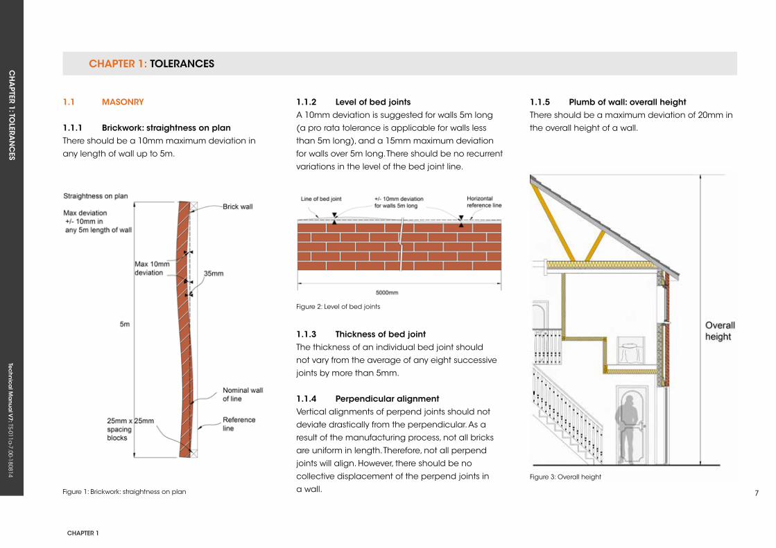
1.1.1 Brickwork: straightness on planThere should be a 10mm maximum deviation in
any length of wall up to 5m.
1.1.2 Level of bed jointsA 10mm deviation is suggested for walls 5m long
(a pro rata tolerance is applicable for walls less
than 5m long), and a 15mm maximum deviation
for walls over 5m long. There should be no recurrent
variations in the level of the bed joint line.
1.1.3 Thickness of bed jointThe thickness of an individual bed joint should
not vary from the average of any eight successive
joints by more than 5mm.
1.1.4 Perpendicular alignmentVertical alignments of perpend joints should not
deviate drastically from the perpendicular. As a
result of the manufacturing process, not all bricks
are uniform in length. Therefore, not all perpend
joints will align. However, there should be no
collective displacement of the perpend joints in
a wall.
1.1.5 Plumb of wall: overall heightThere should be a maximum deviation of 20mm in
the overall height of a wall.
Figure 1: Brickwork: straightness on plan
Figure 2: Level of bed joints
Figure 3: Overall height
CHAPTER 1: TOLERANCESCH
APTER 1: TO
LERAN
CES
Tec
hn
ica
l Ma
nua
l V7: TS-011a
-7.00-180814
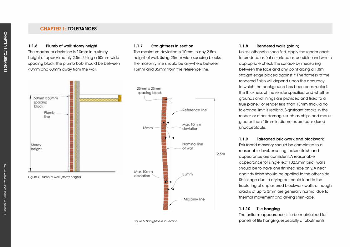
1.1.6 Plumb of wall: storey heightThe maximum deviation is 10mm in a storey
height of approximately 2.5m. using a 50mm wide
spacing block, the plumb bob should be between
40mm and 60mm away from the wall.
1.1.7 straightness in sectionThe maximum deviation is 10mm in any 2.5m
height of wall. using 25mm wide spacing blocks,
the masonry line should be anywhere between
15mm and 35mm from the reference line.
1.1.8 rendered walls (plain)unless otherwise specified, apply the render coats
to produce as flat a surface as possible, and where
appropriate check the surface by measuring
between the face and any point along a 1.8m
straight edge placed against it. The flatness of the
rendered finish will depend upon the accuracy
to which the background has been constructed,
the thickness of the render specified and whether
grounds and linings are provided and fixed to a
true plane. For render less than 13mm thick, a no
tolerance limit is realistic. Significant cracks in the
render, or other damage, such as chips and marks
greater than 15mm in diameter, are considered
unacceptable.
1.1.9 fair-faced brickwork and blockworkFair-faced masonry should be completed to a
reasonable level, ensuring texture, finish and
appearance are consistent. A reasonable
appearance for single leaf 102.5mm brick walls
should be to have one finished side only. A neat
and tidy finish should be applied to the other side.
Shrinkage due to drying out could lead to the
fracturing of unplastered blockwork walls, although
cracks of up to 3mm are generally normal due to
thermal movement and drying shrinkage.
1.1.10 Tile hangingThe uniform appearance is to be maintained for
panels of tile hanging, especially at abutments.
Figure 4: Plumb of wall (storey height)
Figure 5: Straightness in section
CHAPTER 1: TOLERANCESCH
APTER 1: TO
LERAN
CES
Tec
hn
ica
l Ma
nua
l V7: TS-011a
-7.00-180814
CHAPTER 1
9
1.3 JunCTions
If there are changes in the construction materials
used due to shrinkage and the differential
movement of materials; small cracks (up to 3mm
wide) may become visible in the surface at wall,
floor and ceiling junctions.
1.4 fLoors
Floors up to 6m across can be a maximum of 4mm
out of level per metre, and a maximum of 25mm
overall for larger spans. The effects of normal drying
shrinkage on screeded floors could cause some
fracturing. Shrinkage of timber floors and staircases
is a natural occurrence when drying out, which
could result in the squeaking of materials as they
move against each other. This again is a natural
occurrence, and cannot be eliminated entirely.
On upper floors (intermediate floors), although
the permissible deflection may be in accordance
with a relevant British Standard or TRADA
recommendation, deflections must be within the
tolerances defined in this Chapter.
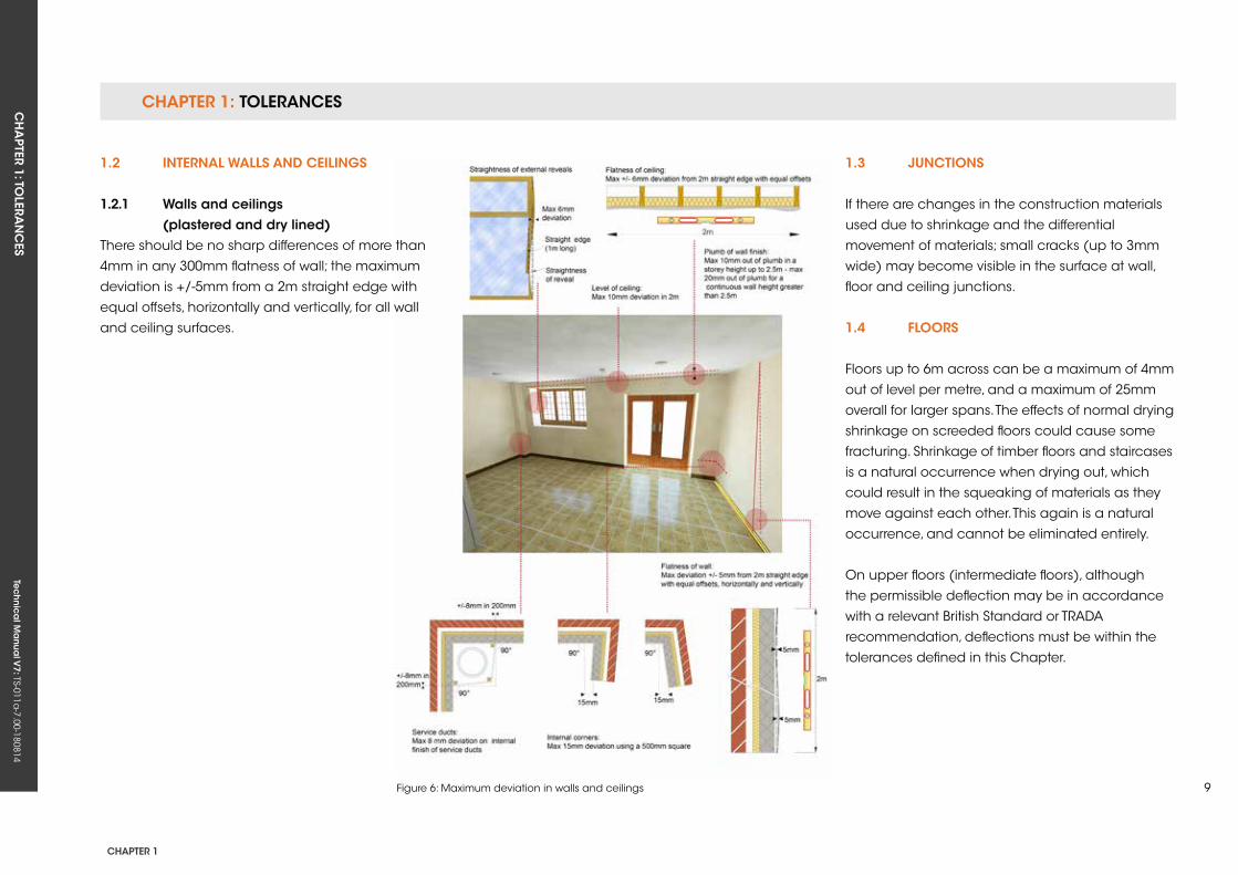
Figure 6: Maximum deviation in walls and ceilings
1.2 inTernAL WALLs AnD CeiLings
1.2.1 Walls and ceilings (plastered and dry lined)There should be no sharp differences of more than
4mm in any 300mm flatness of wall; the maximum
deviation is +/-5mm from a 2m straight edge with
equal offsets, horizontally and vertically, for all wall
and ceiling surfaces.
CHAPTER 1: TOLERANCESCH
APTER 1: TO
LERAN
CES
Tec
hn
ica
l Ma
nua
l V7: TS-011a
-7.00-180814
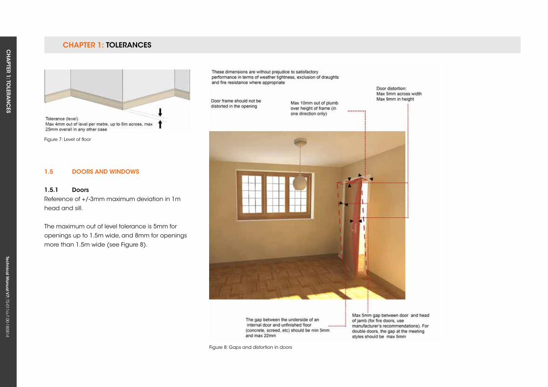
1.5 Doors AnD WinDoWs
1.5.1 Doors Reference of +/-3mm maximum deviation in 1m
head and sill.
The maximum out of level tolerance is 5mm for
openings up to 1.5m wide, and 8mm for openings
more than 1.5m wide (see Figure 8).
Figure 8: Gaps and distortion in doors
Figure 7: Level of floor
CHAPTER 1: TOLERANCESCH
APTER 1: TO
LERAN
CES
Tec
hn
ica
l Ma
nua
l V7: TS-011a
-7.00-180814
CHAPTER 1
11
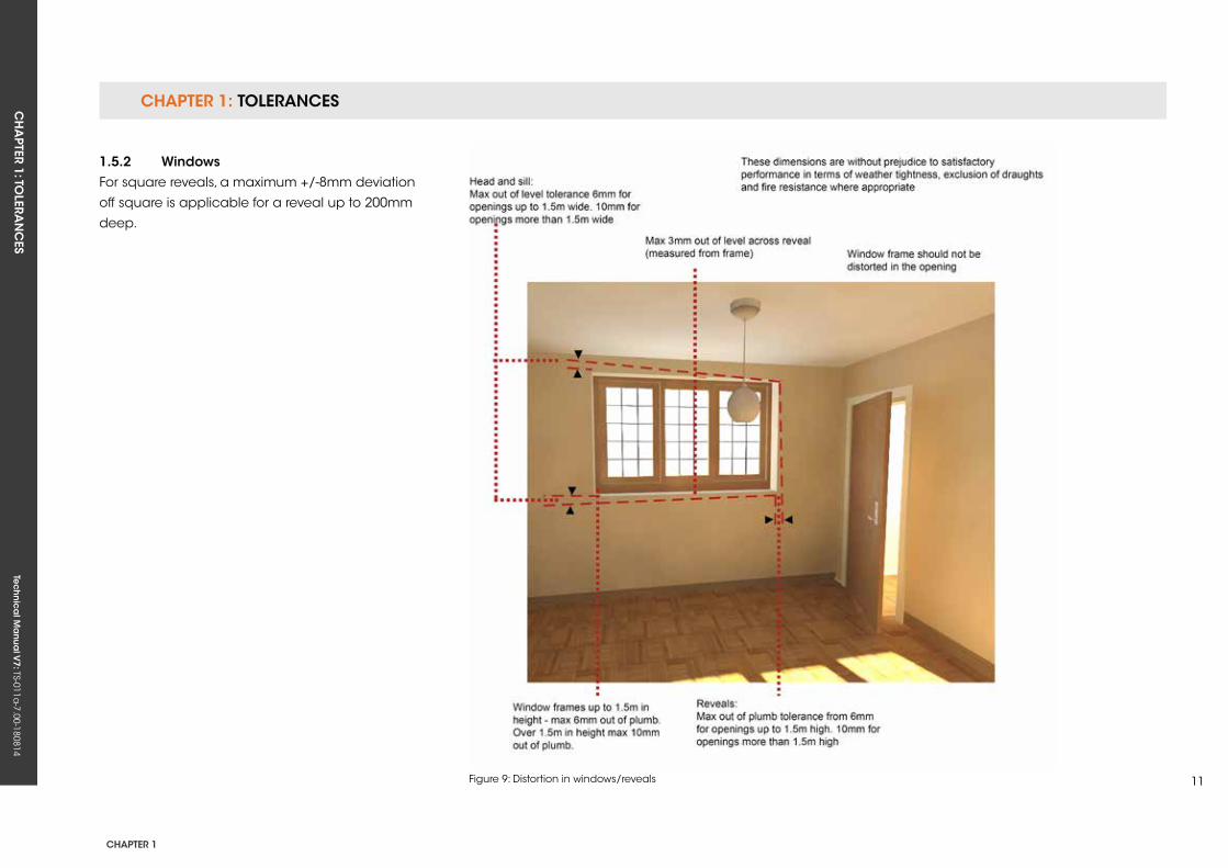
1.5.2 WindowsFor square reveals, a maximum +/-8mm deviation
off square is applicable for a reveal up to 200mm
deep.
Figure 9: Distortion in windows/reveals
CHAPTER 1: TOLERANCESCH
APTER 1: TO
LERAN
CES
Tec
hn
ica
l Ma
nua
l V7: TS-011a
-7.00-180814
1.5.3 glazingGlass must meet the visual assessment criteria of
CWCT Technical Note 35 (TN 35). The total number
of faults permitted in a glass unit shall be the sum
total of those permitted by the relevant BS EN
Standard for each pane of glass incorporated into
the unit concerned.
Faults include:
• Bubbles or blisters
• Hairlines or blobs
• Fine scratches not more than 25mm long
• Minute particles
When assessing the appearance of glass:
• The viewing distance used shall be the furthest
stated in any of the BS EN Standards for the
glass types incorporated in the glazed unit. In
the event of doubt, the viewing distance shall
be 3m.
• The viewing shall commence at the viewing
distance, and shall not be preceded by viewing
at a closer distance.
• The viewing shall be undertaken in normal
daylight conditions, without use of
magnification.
• The above does not apply within 6mm of the
edge of the pane, where minor scratching is
acceptable.
1.5.4 scratches on doors, windows and framesFactory-finished door and window components
should not have conspicuous abrasions or
scratches when viewed from a distance of 0.5m.
• Surface abrasions caused during the building-
in process should be removed in accordance
with the manufacturer’s instructions, which may
include polishing out, re-spraying or painting.
• In rooms where there is no daylight, scratches
should be viewed in artificial light from fixed wall
or ceiling outlets, and not from portable equipment.
1.6 skirTings
It is possible that there will be joints in skirtings on
long walls. When viewed from a distance of 2m
in daylight, joints will need to show a consistent
appearance. It is anticipated that there will
be some initial shrinkage of the skirting after
occupation of the building.
1.7 finisHes AnD fiTTeD furniTure
Fitted furniture with doors and drawers should be
aligned vertically, horizontally and in plan. It should
also function as designed by the manufacturer.
Adjacent doors and/or drawers with any gaps
between them should be consistent. At the
intersection of adjacent worktops, there should not
be a visible change in level.
1.7.1 Painted and varnished surfacesAll surfaces should be smooth, and nail holes,
cracks and splits should not be seen. Colour,
texture and finish should be consistent, with any
joints filled where necessary.
1.7.2 knots in timberSome seeping of resin from knots is a natural
occurrence that may cause paintwork
discolouration both internally and externally.
The standard will be met providing the Developer
finishes the timber in accordance with Functional
Requirements.
1.8 exTernAL Works
1.8.1 Drives and paths: standing waterSurface variation should not exceed +/-10mm
from a 2m straight edge with equal offsets. Some
fracturing or weathering may also appear if using
natural stone due to the make-up of the material.
This tolerance applies to principle pathways and
driveways to the dwelling that are required to meet
the standards of Part M (Access to Dwellings).
1.8.2 Drainage system coversDrainage system covers in hard standing areas
should line up neatly with the adjacent ground.
CH
APTER 2: M
ATERIA
LSTe
ch
nic
al M
anu
al V
7: TS-011a-7.00-180814
CHAPTER 2
13
CHAPTer 2: MATeriALs
ConTenTs
2.1 TIMBER
2.2 CONCRETE
2.3 OTHER COMPONENTS
Tec
hn
ica
l Ma
nua
l V6: TS-011a
-6.00-010413Te
ch
nic
al M
anu
al V
7: TS-011a-7.00-180814
FUNCTIONAL REQUIREMENTS
2.1 TiMBer
Workmanshipi. All workmanship must be within the tolerances defined in Chapter 1
of this Manual.
ii. All work is to be carried out by a technically competent person in
a workmanlike manner.
Materialsi. All materials should be stored correctly in a manner that will not
cause damage or deterioration of the product.
ii. All materials, products and building systems shall be appropriate
and suitable for their intended purpose.
iii. External timber should be adequately treated or finished to resist
insect attacks. Timber treatment should be in accordance with
relevant British Standards and Codes of Practice.
iv. The structure shall, unless specifically agreed otherwise with the
Warranty provider, have a life of not less than 60 years. Individual
components and assemblies, not integral to the structure, may have a
lesser durability, but not in any circumstances less than 15 years.
v. Timber used in the dwelling to provide support to the structure must
be appropriately seasoned to prevent excessive shrinkage and
movement.
Designi. The design and specifications shall provide a clear indication of the
design intent and demonstrate a satisfactory level of performance.
ii. Structural elements outside the parameters of regional Approved
Documents must be supported by structural calculations provided by
a suitably qualified expert.
iii. The materials used for construction must meet the relevant Building
Regulations, Eurocodes and other statutory requirements.
iv. Specialist works must be provided and supported by structural
calculations completed by a suitably qualified Engineer where
necessary.
v. Any engineered beams/posts manufactured off-site must have
structural calculations endorsed by the manufacturer.
CHAPTER 2: MATERIALSCH
APTER 2: M
ATERIA
LS Te
ch
nic
al M
anu
al V
7: TS-011a-7.00-180814
CHAPTER 2
15
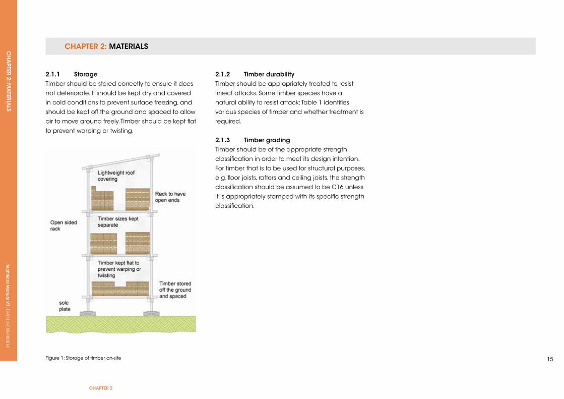
2.1.1 storageTimber should be stored correctly to ensure it does
not deteriorate. It should be kept dry and covered
in cold conditions to prevent surface freezing, and
should be kept off the ground and spaced to allow
air to move around freely. Timber should be kept flat
to prevent warping or twisting.
Figure 1: Storage of timber on-site
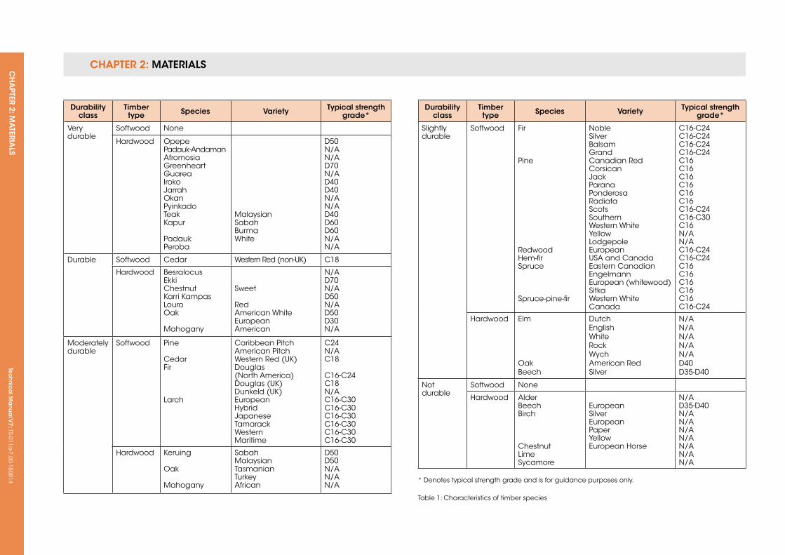
2.1.2 Timber durabilityTimber should be appropriately treated to resist
insect attacks. Some timber species have a
natural ability to resist attack; Table 1 identifies
various species of timber and whether treatment is
required.
2.1.3 Timber gradingTimber should be of the appropriate strength
classification in order to meet its design intention.
For timber that is to be used for structural purposes,
e.g. floor joists, rafters and ceiling joists, the strength
classification should be assumed to be C16 unless
it is appropriately stamped with its specific strength
classification.
CHAPTER 2: MATERIALSCH
APTER 2: M
ATERIA
LSTe
ch
nic
al M
anu
al V
7: TS-011a-7.00-180814
Durability class
Timber type species variety Typical strength
grade*
Very durable
Softwood None
Hardwood OpepePadauk-AndamanAfromosiaGreenheartGuareaIrokoJarrahOkanPyinkadoTeakkapur
PadaukPeroba
MalaysianSabahBurmaWhite
D50N/AN/AD70N/AD40D40N/AN/AD40D60D60N/AN/A
Durable Softwood Cedar Western Red (non-uk) C18
Hardwood BesralocusEkkiChestnutkarri kampasLouroOak
Mahogany
Sweet
RedAmerican WhiteEuropeanAmerican
N/AD70N/AD50N/AD50D30N/A
Moderately durable
Softwood Pine
CedarFir
Larch
Caribbean PitchAmerican PitchWestern Red (uk)Douglas (North America)Douglas (uk)Dunkeld (uk)EuropeanHybridJapaneseTamarackWesternMaritime
C24N/AC18
C16-C24C18N/AC16-C30C16-C30C16-C30C16-C30C16-C30C16-C30
Hardwood keruing
Oak
Mahogany
SabahMalaysianTasmanianTurkeyAfrican
D50D50N/A N/AN/A
Durability class
Timber type species variety Typical strength
grade*
Slightly durable
Softwood Fir
Pine
RedwoodHem-firSpruce
Spruce-pine-fir
NobleSilverBalsamGrandCanadian RedCorsicanJackParanaPonderosaRadiataScotsSouthernWestern WhiteyellowLodgepoleEuropeanuSA and CanadaEastern CanadianEngelmannEuropean (whitewood)SitkaWestern WhiteCanada
C16-C24C16-C24C16-C24C16-C24C16C16C16C16C16C16C16-C24C16-C30C16N/AN/AC16-C24C16-C24C16C16C16C16C16C16-C24
Hardwood Elm
OakBeech
DutchEnglishWhiteRockWychAmerican RedSilver
N/AN/AN/AN/AN/AD40D35-D40
Not durable
Softwood None
Hardwood Alder BeechBirch
ChestnutLimeSycamore
EuropeanSilverEuropeanPaperyellowEuropean Horse
N/AD35-D40N/AN/AN/AN/AN/AN/AN/A
* Denotes typical strength grade and is for guidance purposes only.
Table 1: Characteristics of timber species
CHAPTER 2: MATERIALSCH
APTER 2: M
ATERIA
LS Te
ch
nic
al M
anu
al V
7: TS-011a-7.00-180814
CHAPTER 2
17
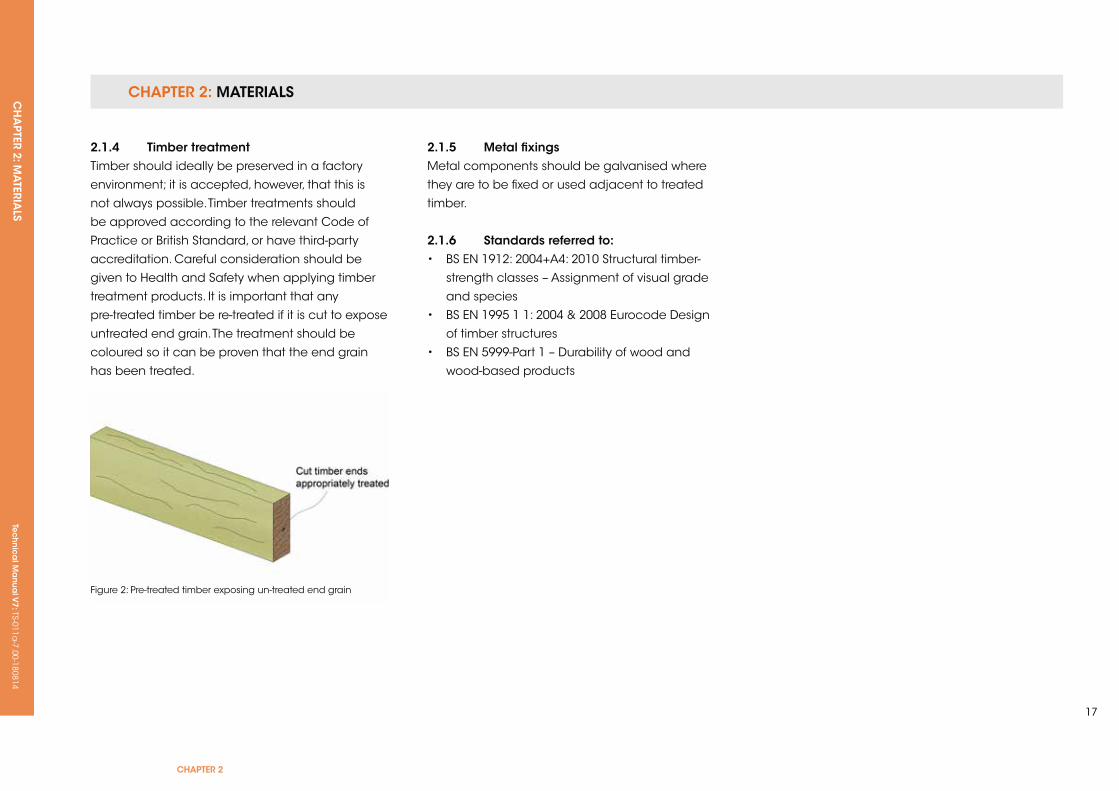
2.1.4 Timber treatmentTimber should ideally be preserved in a factory
environment; it is accepted, however, that this is
not always possible. Timber treatments should
be approved according to the relevant Code of
Practice or British Standard, or have third-party
accreditation. Careful consideration should be
given to Health and Safety when applying timber
treatment products. It is important that any
pre-treated timber be re-treated if it is cut to expose
untreated end grain. The treatment should be
coloured so it can be proven that the end grain
has been treated.
2.1.5 Metal fixingsMetal components should be galvanised where
they are to be fixed or used adjacent to treated
timber.
2.1.6 standards referred to:• BS EN 1912: 2004+A4: 2010 Structural timber-
strength classes – Assignment of visual grade
and species
• BS EN 1995 1 1: 2004 & 2008 Eurocode Design
of timber structures
• BS EN 5999-Part 1 – Durability of wood and
wood-based products
Figure 2: Pre-treated timber exposing un-treated end grain
Tec
hn
ica
l Ma
nua
l V6: TS-011a
-6.00-010413Te
ch
nic
al M
anu
al V
7: TS-011a-7.00-180814
FUNCTIONAL REQUIREMENTS
2.2 ConCreTe
Workmanshipi. All workmanship must be within the tolerances defined in Chapter 1
of this Manual.
ii. All work is to be carried out by a technically competent person in
a workmanlike manner.
iii. Concreting shall not take place during cold weather periods or
where ground conditions are frozen.
Materialsi. All materials should be stored correctly in a manner that will not cause
damage or deterioration of the product.
ii. All materials, products and building systems shall be appropriate
and suitable for their intended purpose.
iii. The structure shall, unless specifically agreed otherwise with the
Warranty provider, have a life of not less than 60 years. Individual
components and assemblies, not integral to the structure, may have
a lesser durability, but not in any circumstances less than 15 years.
Designi. The design and specifications shall provide a clear indication of the
design intent and demonstrate a satisfactory level of performance.
ii. Structural elements outside the parameters of regional Approved
Documents must be supported by structural calculations provided by
a suitably qualified expert.
iii. The materials used for construction must meet the relevant Building
Regulations, Eurocodes and other statutory requirements.
iv. Reinforced concrete elements must be supported by structural
calculations and details produced by a suitably qualified Structural
Engineer.
v. Precast structural elements must have structural calculations that
prove their adequacy, as endorsed by the manufacturer.
CHAPTER 2: MATERIALSCH
APTER 2: M
ATERIA
LS Te
ch
nic
al M
anu
al V
7: TS-011a-7.00-180814
CHAPTER 2
19
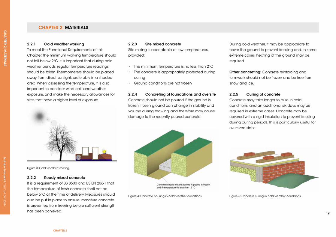
2.2.1 Cold weather working To meet the Functional Requirements of this
Chapter, the minimum working temperature should
not fall below 2°C. It is important that during cold
weather periods, regular temperature readings
should be taken. Thermometers should be placed
away from direct sunlight, preferably in a shaded
area. When assessing the temperature, it is also
important to consider wind chill and weather
exposure, and make the necessary allowances for
sites that have a higher level of exposure.
Figure 3: Cold weather working
2.2.2 ready mixed concreteIt is a requirement of BS 8500 and BS EN 206-1 that
the temperature of fresh concrete shall not be
below 5°C at the time of delivery. Measures should
also be put in place to ensure immature concrete
is prevented from freezing before sufficient strength
has been achieved.
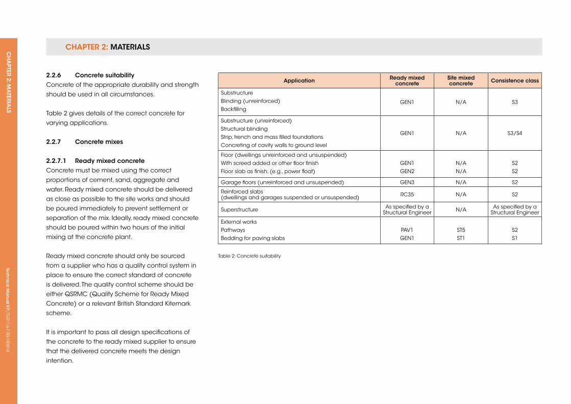
Figure 4: Concrete pouring in cold weather conditions
2.2.3 site mixed concreteSite mixing is acceptable at low temperatures,
provided:
• The minimum temperature is no less than 2°C
• The concrete is appropriately protected during
curing
• Ground conditions are not frozen
2.2.4 Concreting of foundations and oversiteConcrete should not be poured if the ground is
frozen; frozen ground can change in stability and
volume during thawing, and therefore may cause
damage to the recently poured concrete.
During cold weather, it may be appropriate to
cover the ground to prevent freezing and, in some
extreme cases, heating of the ground may be
required.
other concreting: Concrete reinforcing and
formwork should not be frozen and be free from
snow and ice.
2.2.5 Curing of concreteConcrete may take longer to cure in cold
conditions, and an additional six days may be
required in extreme cases. Concrete may be
covered with a rigid insulation to prevent freezing
during curing periods. This is particularly useful for
oversized slabs.
Figure 5: Concrete curing in cold weather conditions
CHAPTER 2: MATERIALSCH
APTER 2: M
ATERIA
LSTe
ch
nic
al M
anu
al V
7: TS-011a-7.00-180814
Application ready mixed concrete
site mixed concrete Consistence class
SubstructureBlinding (unreinforced)Backfilling
GEN1 N/A S3
Substructure (unreinforced)Structural blindingStrip, trench and mass filled foundationsConcreting of cavity walls to ground level
GEN1 N/A S3/S4
Floor (dwellings unreinforced and unsuspended)With screed added or other floor finishFloor slab as finish, (e.g., power float)
GEN1GEN2
N/AN/A
S2S2
Garage floors (unreinforced and unsuspended) GEN3 N/A S2
Reinforced slabs (dwellings and garages suspended or unsuspended) RC35 N/A S2
Superstructure As specified by a Structural Engineer N/A As specified by a
Structural Engineer
External worksPathwaysBedding for paving slabs
PAV1GEN1
ST5ST1
S2S1
Table 2: Concrete suitability
2.2.6 Concrete suitabilityConcrete of the appropriate durability and strength
should be used in all circumstances.
Table 2 gives details of the correct concrete for
varying applications.
2.2.7 Concrete mixes
2.2.7.1 ready mixed concreteConcrete must be mixed using the correct
proportions of cement, sand, aggregate and
water. Ready mixed concrete should be delivered
as close as possible to the site works and should
be poured immediately to prevent settlement or
separation of the mix. Ideally, ready mixed concrete
should be poured within two hours of the initial
mixing at the concrete plant.
Ready mixed concrete should only be sourced
from a supplier who has a quality control system in
place to ensure the correct standard of concrete
is delivered. The quality control scheme should be
either qSRMC (quality Scheme for Ready Mixed
Concrete) or a relevant British Standard kitemark
scheme.
It is important to pass all design specifications of
the concrete to the ready mixed supplier to ensure
that the delivered concrete meets the design
intention.
CHAPTER 2: MATERIALSCH
APTER 2: M
ATERIA
LS Te
ch
nic
al M
anu
al V
7: TS-011a-7.00-180814
CHAPTER 2
21
Delivery notes should be kept and made available
for inspection if required.
Additional water should not be added to the
concrete on-site; nor should the ready mixed
concrete be poured into water filled trenches
unless the concrete has been specifically designed
for this purpose.
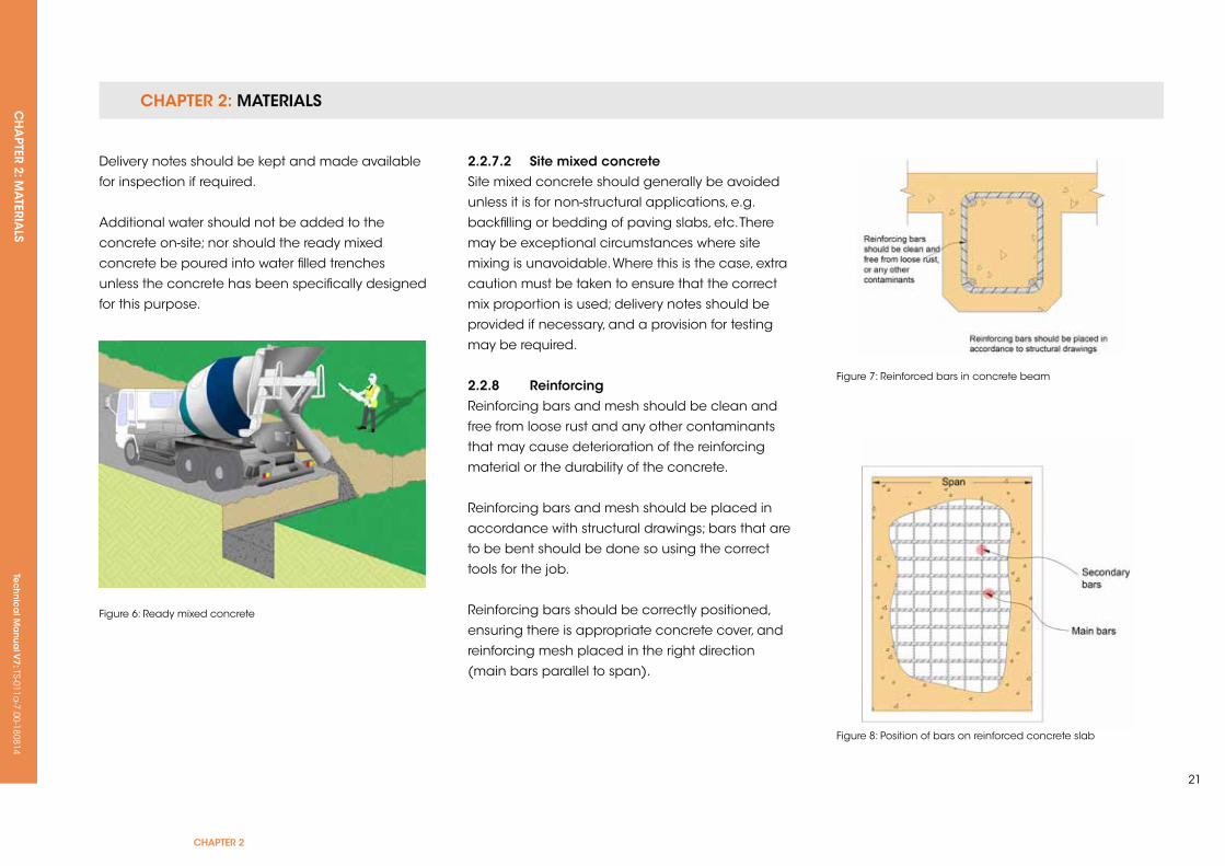
Figure 6: Ready mixed concrete
Figure 8: Position of bars on reinforced concrete slab
Figure 7: Reinforced bars in concrete beam
2.2.7.2 site mixed concreteSite mixed concrete should generally be avoided
unless it is for non-structural applications, e.g.
backfilling or bedding of paving slabs, etc. There
may be exceptional circumstances where site
mixing is unavoidable. Where this is the case, extra
caution must be taken to ensure that the correct
mix proportion is used; delivery notes should be
provided if necessary, and a provision for testing
may be required.
2.2.8 reinforcingReinforcing bars and mesh should be clean and
free from loose rust and any other contaminants
that may cause deterioration of the reinforcing
material or the durability of the concrete.
Reinforcing bars and mesh should be placed in
accordance with structural drawings; bars that are
to be bent should be done so using the correct
tools for the job.
Reinforcing bars should be correctly positioned,
ensuring there is appropriate concrete cover, and
reinforcing mesh placed in the right direction
(main bars parallel to span).
CHAPTER 2: MATERIALSCH
APTER 2: M
ATERIA
LSTe
ch
nic
al M
anu
al V
7: TS-011a-7.00-180814
2.2.8.1 reinforcing coverAn appropriate level of concrete cover should be
provided to the reinforcing; the cover thickness will
depend on the exposure of the concrete and its
application. Concrete cover should be specified by
a qualified Structural Engineer, or alternatively by
using Table 3.
Application (concrete position) Minimum cover (mm)
Concrete in direct contact with the ground 75
All external applications e.g. shuttered walling 50
Floor slabs and other applications where concrete is cast onto a membrane
40
Concrete over blinding concrete 40
Internal conditions 25
Table 3: Minimum concrete reinforcing cover
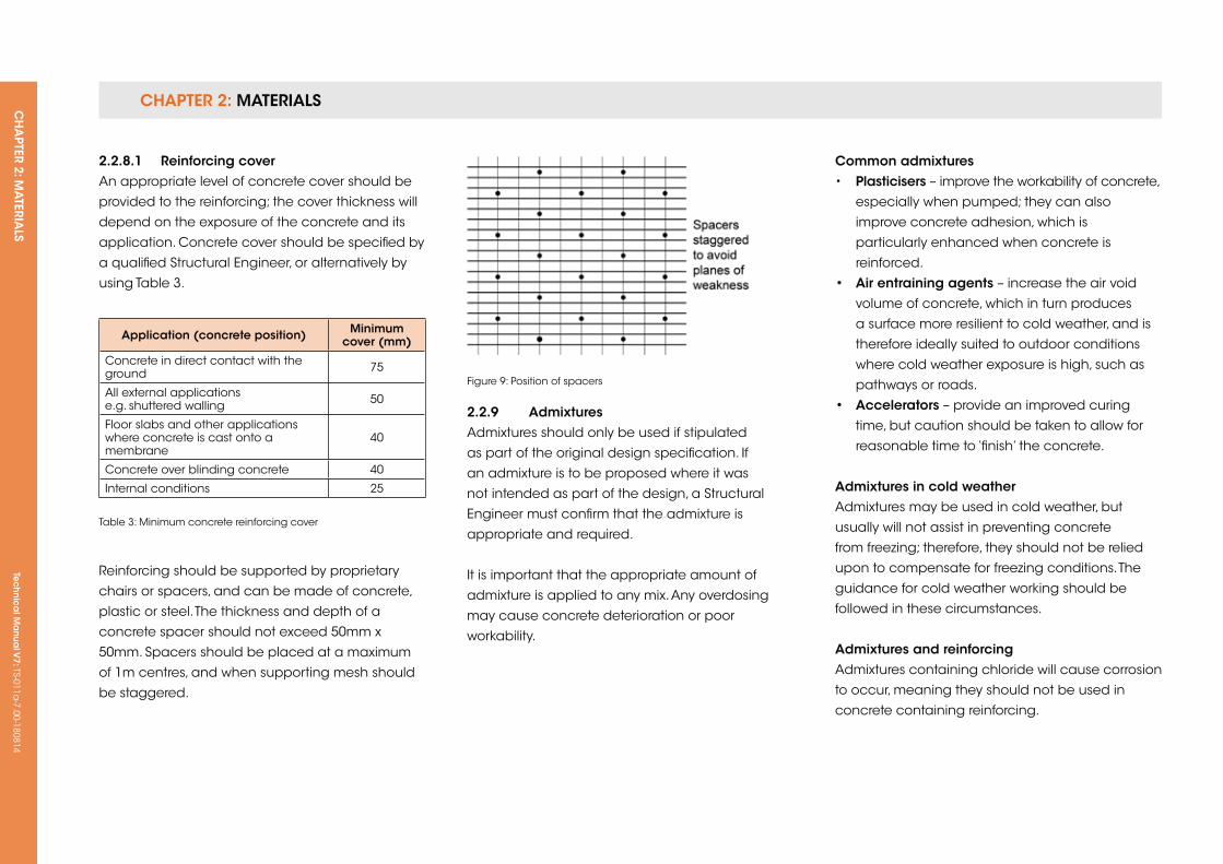
Reinforcing should be supported by proprietary
chairs or spacers, and can be made of concrete,
plastic or steel. The thickness and depth of a
concrete spacer should not exceed 50mm x
50mm. Spacers should be placed at a maximum
of 1m centres, and when supporting mesh should
be staggered.
Figure 9: Position of spacers
2.2.9 AdmixturesAdmixtures should only be used if stipulated
as part of the original design specification. If
an admixture is to be proposed where it was
not intended as part of the design, a Structural
Engineer must confirm that the admixture is
appropriate and required.
It is important that the appropriate amount of
admixture is applied to any mix. Any overdosing
may cause concrete deterioration or poor
workability.
Common admixtures• Plasticisers – improve the workability of concrete,
especially when pumped; they can also
improve concrete adhesion, which is
particularly enhanced when concrete is
reinforced.
• Air entraining agents – increase the air void
volume of concrete, which in turn produces
a surface more resilient to cold weather, and is
therefore ideally suited to outdoor conditions
where cold weather exposure is high, such as
pathways or roads.
• Accelerators – provide an improved curing
time, but caution should be taken to allow for
reasonable time to ‘finish’ the concrete.
Admixtures in cold weatherAdmixtures may be used in cold weather, but
usually will not assist in preventing concrete
from freezing; therefore, they should not be relied
upon to compensate for freezing conditions. The
guidance for cold weather working should be
followed in these circumstances.
Admixtures and reinforcingAdmixtures containing chloride will cause corrosion
to occur, meaning they should not be used in
concrete containing reinforcing.
CHAPTER 2: MATERIALSCH
APTER 2: M
ATERIA
LS Te
ch
nic
al M
anu
al V
7: TS-011a-7.00-180814
CHAPTER 2
23
2.2.10 expansion/movement jointsJoints in concrete should be provided to prevent
cracking caused by shrinkage; shrinkage will be
less significant if the concrete is reinforced.
A larger number of expansion joints should be
provided to concrete where weak spots may occur.
This could include a narrowing width of floor slab
for example.
2.2.11 vibration and compaction of concreteReinforced concrete should be compacted using
a vibrating poker, but care must be taken to ensure
the concrete is not over-compacted and the
concrete mix separated. Tamping of floors by hand
is acceptable for floor slabs that do not exceed
150mm in thickness.
2.2.12 Curing of concreteConcrete should be adequately cured before
loads are applied. It is acceptable that masonry
walls may be built up to Damp Proof Course (DPC)
on a foundation that is not fully cured; however,
care must be taken to prevent any damage to
the foundation. The concrete should be at least
durable enough to carry the masonry.
The speed at which concrete mixes cure depends
on the mix ratio and whether there are any
additives within the concrete. Where curing time
is critical, such as cast in-situ upper floors, curing
times should be indicated as part of the design
and formwork struck, as advised by a Structural
Engineer.
To prevent concrete curing too rapidly after initial
drying, exposed concrete should be covered
with hessian, polythene or sand. This prevents
the surface drying too quickly and protects the
concrete. This level of protection is particularly
critical in hot or adverse weather conditions.
2.2.13 standards referred to:• BS 8110 Structural use of concrete
• BS EN 1992 – 1-1 Design of concrete structures,
general rules and rules for buildings
(incorporating uk National Annex to Eurocode)
• BS 8500 Concrete – Complementary British
Standard to BS EN 206-1
• BS EN 206-1 Concrete. Specification,
performance, production and conformity
• BS EN 12620 Aggregates for concrete
• BS EN 197 Cement. Conformity evaluation
Tec
hn
ica
l Ma
nua
l V6: TS-011a
-6.00-010413Te
ch
nic
al M
anu
al V
7: TS-011a-7.00-180814
FUNCTIONAL REQUIREMENTS
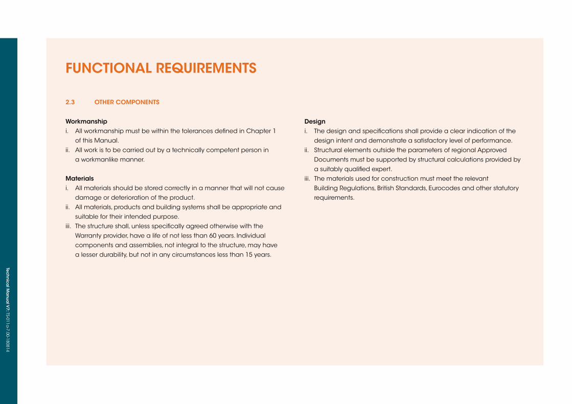
2.3 oTHer CoMPonenTs
Workmanshipi. All workmanship must be within the tolerances defined in Chapter 1
of this Manual.
ii. All work is to be carried out by a technically competent person in
a workmanlike manner.
Materialsi. All materials should be stored correctly in a manner that will not cause
damage or deterioration of the product.
ii. All materials, products and building systems shall be appropriate and
suitable for their intended purpose.
iii. The structure shall, unless specifically agreed otherwise with the
Warranty provider, have a life of not less than 60 years. Individual
components and assemblies, not integral to the structure, may have
a lesser durability, but not in any circumstances less than 15 years.
Design i. The design and specifications shall provide a clear indication of the
design intent and demonstrate a satisfactory level of performance.
ii. Structural elements outside the parameters of regional Approved
Documents must be supported by structural calculations provided by
a suitably qualified expert.
iii. The materials used for construction must meet the relevant
Building Regulations, British Standards, Eurocodes and other statutory
requirements.

CHAPTER 2: MATERIALSCH
APTER 2: M
ATERIA
LS Te
ch
nic
al M
anu
al V
7: TS-011a-7.00-180814
CHAPTER 2
25Figure 10: Protection of blockwork
Figure 11: Protection of masonry walls
2.3.1 Cold weather workingTo meet the Functional Requirements of this
Chapter, minimum working temperatures should
not fall below 2°C when working with masonry.
It is important that during cold weather periods,
regular temperature readings should be taken.
Thermometers should be placed away from
direct sunlight, preferably in a shaded area. When
assessing the temperature, it is also important to
consider wind chill and weather exposure, and
make necessary allowances for sites that have a
higher level of exposure.
2.3.1.1 Protection of materialsCovers should be provided to protect materials
from frost, snow and ice, particularly bricks, blocks,
sand and cement. Frozen materials should never
be used under any circumstances.
2.3.1.2 Protection of masonryAny new walls or other masonry construction will
require protection against frost where temperatures
are expected to drop below 2°C. Ideally, all
masonry should be protected with polythene or
hessian. If temperatures are expected to fall to
an extremely low level, insulation boards may be
required, and heating may even be considered.
2.3.1.3 finishes including rendering, plastering and screedsRendering should only be completed if the outside
temperature is at least 2°C; there should be no frost
within the construction that is to be rendered and,
where possible, rendering should not take place
where freezing weather conditions are anticipated
prior to adequate curing.
No plastering or screeding should take place
unless the building is free from frost. It is acceptable
to use internal heating to warm the building
effectively; however, it is important to ensure that
heaters do not emit excessive vapour into the
dwelling. Adequate ventilation should be provided
to allow moist air to escape. The dwelling should
be appropriately pre-heated before plastering, and
continue to be heated whilst the plaster dries.
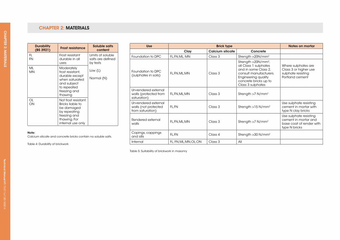
2.3.2 Masonry
2.3.2.1 Bricks Bricks should be of an appropriate durability to
meet the design intention. The type of brick to be
used will affect the specification of the mortar.
Bricks with greater durability should be used where
there is a higher potential for saturation or severe
exposure to wind-driven rain.
CHAPTER 2: MATERIALSCH
APTER 2: M
ATERIA
LSTe
ch
nic
al M
anu
al V
7: TS-011a-7.00-180814
Durability(Bs 3921) frost resistance soluble salts
content
FLFN
Frost resistant durable in all uses
Limits of soluble salts are defined by tests
Low (L)
Normal (N)
MLMN
Moderately frost resistant, durable except when saturated and subject to repeated freezing and thawing
OLON
Not frost resistant. Bricks liable to be damaged by repeating freezing and thawing. For internal use only
note:Calcium silicate and concrete bricks contain no soluble salts.
Table 4: Durability of brickwork
use Brick type notes on mortar
Clay Calcium silicate Concrete
Foundation to DPC FL,FN,ML, MN Class 3 Strength >20N/mm2
Foundation to DPC (sulphates in soils) FL,FN,ML,MN Class 3
Strength >20N/mm2, all Class 1 sulphates and in some Class 2, consult manufacturers. Engineering quality concrete bricks up to Class 3 sulphates
Where sulphates are Class 3 or higher use sulphate resisting Portland cement
un-rendered external walls (protected from saturation)
FL,FN,ML,MN Class 3 Strength >7 N/mm2
un-rendered external walls (not protected from saturation)
FL,FN Class 3 Strength >15 N/mm2use sulphate resisting cement in mortar with type N clay bricks
Rendered external walls FL,FN,ML,MN Class 3 Strength >7 N/mm2
use sulphate resisting cement in mortar and base coat of render with type N bricks
Copings, cappings and sills FL,FN Class 4 Strength >30 N/mm2
Internal FL, FN,ML,MN,OL,ON Class 3 All
Table 5: Suitability of brickwork in masonry
CHAPTER 2: MATERIALSCH
APTER 2: M
ATERIA
LS Te
ch
nic
al M
anu
al V
7: TS-011a-7.00-180814
CHAPTER 2
27
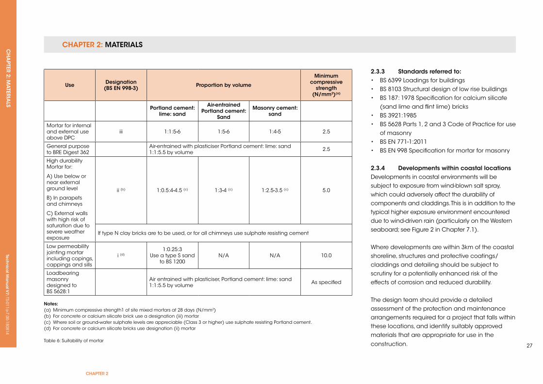
use Designation(Bs en 998-3) Proportion by volume
Minimum compressive
strength (n/mm2)(a)
Portland cement: lime: sand
Air-entrained Portland cement:
sand
Masonry cement: sand
Mortar for internal and external use above DPC
iii 1:1:5-6 1:5-6 1:4-5 2.5
General purpose to BRE Digest 362
Air-entrained with plasticiser Portland cement: lime: sand 1:1:5.5 by volume 2.5
High durability Mortar for:
A) use below or near external ground level
B) In parapets and chimneys
C) External walls with high risk of saturation due to severe weather exposure
ii (b) 1:0.5:4-4.5 (c) 1:3-4 (c) 1:2.5-3.5 (c) 5.0
If type N clay bricks are to be used, or for all chimneys use sulphate resisting cement
Low permeability jointing mortar including copings, cappings and sills
i (d)1:0.25:3
use a type S sand to BS 1200
N/A N/A 10.0
Loadbearing masonry designed to BS 5628:1
Air entrained with plasticiser, Portland cement: lime: sand 1:1:5.5 by volume As specified
notes: (a) Minimum compressive strength1 of site mixed mortars at 28 days (N/mm2)(b) For concrete or calcium silicate brick use a designation (iii) mortar(c) Where soil or ground-water sulphate levels are appreciable (Class 3 or higher) use sulphate resisting Portland cement.(d) For concrete or calcium silicate bricks use designation (ii) mortar
Table 6: Suitability of mortar
2.3.3 standards referred to:• BS 6399 Loadings for buildings• BS 8103 Structural design of low rise buildings• BS 187: 1978 Specification for calcium silicate (sand lime and flint lime) bricks• BS 3921:1985• BS 5628 Parts 1, 2 and 3 Code of Practice for use of masonry• BS EN 771-1:2011• BS EN 998 Specification for mortar for masonry
2.3.4 Developments within coastal locationsDevelopments in coastal environments will be subject to exposure from wind-blown salt spray, which could adversely affect the durability of components and claddings. This is in addition to the typical higher exposure environment encountered due to wind-driven rain (particularly on the Western seaboard; see Figure 2 in Chapter 7.1).
Where developments are within 3km of the coastal shoreline, structures and protective coatings/claddings and detailing should be subject to scrutiny for a potentially enhanced risk of the effects of corrosion and reduced durability.
The design team should provide a detailed assessment of the protection and maintenance arrangements required for a project that falls within these locations, and identify suitably approved materials that are appropriate for use in the
construction.
CHAPTER 2: MATERIALSCH
APTER 2: M
ATERIA
LSTe
ch
nic
al M
anu
al V
7: TS-011a-7.00-180814
Shoreline/sea front developments will be
designated as having a ‘very severe’ exposure
risk, and the design team must provide specific
proposals to demonstrate the durability, suitability
and weather tightness of the construction,
particularly for window and door openings,
cladding and roof fixings, together with planned
maintenance programmes to ensure the
construction meets the requirements of this
Manual.
2.3.4.1 further reference• BS 5628 – 3: 2005 Code of Practice for the use
of masonry (superseded by BS EN 1996).
• BS 8104 Code of Practice for assessing exposure
of walls to wind-driven rain
• BS 7543 Guide to durability of buildings and
building elements, products and components
• BS 5493 Code of Practice for protective coating
of iron and steel structures against corrosion
• BS 5427 Code of Practice for the use of profiled
sheet for roof and wall cladding on buildings.
2.3.5 suitability of materialsIt is important to ensure materials used in
construction:
• Meet the requirements of British Standards
or Codes of Practice or equivalent European
Standards current at the time of application
• Are materials/products or systems covered by
a current approval from an independent
third-party technical approval body accepted
bythe Warranty provider . This would either
be a ukAS or European equivalent accredited
organisation, such as ILAC (International
Laboratory Accreditation Co-operation). Details
of the testing body accreditation will need to be
supplied, as well as the certification document
In addition:
• The independent third-party testing
information must recognise uk Building
Regulation requirements and additional
Warranty standards. Details of the performance
and the limitations of use of the material/
product or system tested must be provided
• Where bearing a CE marking in accordance
with the Construction Products Directive, this
shall be supported by evidence of the testing
carried out on the product
Construction products that do not meet the
requirements of this Technical Manual may not
be acceptable for Warranty approval. It is advised
that the design team must approach the Warranty
provider early in the design stage to discuss
the viability of the use of such a material, and
determine what further independent third-party
testing may be required in advance of the final
design proposal.
CH
APTER 3: M
OD
ERN M
ETHO
DS O
F CO
NSTRU
CTIO
N (M
MC
)Te
ch
nic
al M
anu
al V
7: TS-011a-7.00-180814
CHAPTER 3
29
CHAPTer 3: MoDern MeTHoDs of ConsTruCTion (MMC)
ConTenTs
3.1.1 INTRODuCTION
3.1.2 SuITABILITy OF SySTEMS AND COMPONENTS
3.1.3 TyPES OF MODERN METHODS OF CONSTRuCTION (MMC)
3.1.4 SuITABILITy OF SySTEMS TO MEET WARRANTy REquIREMENTS
Tec
hn
ica
l Ma
nua
l V6: TS-011a
-6.00-010413Te
ch
nic
al M
anu
al V
7: TS-011a-7.00-180814
FUNCTIONAL REQUIREMENTS
Workmanshipi. All workmanship must be within the tolerances defined in Chapter 1
of this Manual.
ii. All work is to be carried out by a technically competent person in a
workmanlike manner.
iii. Certification is required for any work completed by an approved
installer.
Materialsi. All materials should be stored correctly in a manner that will not cause
damage or deterioration of the product.
ii. All materials, products and building systems shall be appropriate and
suitable for their intended purpose.
iii. The structure shall, unless specifically agreed otherwise with the
Warranty provider, have a life of not less than 60 years. Individual
components and assemblies, not integral to the structure, may have
a lesser durability, but not in any circumstances less than 15 years.
3.1 MoDern MeTHoDs of ConsTruCTion (MMC)
Designi. The design and specifications shall provide a clear indication of the
design intent and demonstrate a satisfactory level of performance.
ii. Structural elements outside the parameters of regional Approved
Documents must be supported by structural calculations provided by
a suitably qualified expert.
iii. The construction must meet the relevant Building Regulations, British
Standards, Eurocodes and other statutory requirements.
iv. All MMC systems must be assessed and approved by a recognised
third-party assessment body.
CHAPTER 3: MODERN METHODS OF CONSTRUCTION (MMC)CH
APTER 3: M
OD
ERN M
ETHO
DS O
F CO
NSTRU
CTIO
N (M
MC
)Te
ch
nic
al M
anu
al V
7: TS-011a-7.00-180814
CHAPTER 3
31
3.1.1 introductionModern methods of construction (MMC) are being
used in the construction industry, particularly for
housing, as they potentially represent savings in
time and materials, and provide higher standards
of quality than more conventional methods of
construction.
key points to note are:
• Off-site assembly means quick erection times
on-site and a quick, weather tight construction
achieved.
• The accurate setting out of foundations, etc.
needs to be managed.
• MMC, particularly modular systems and large
panel systems, will require advanced planning
of the site for access, off-loading, installation
and possibly storage of systems.
• The construction, design and layout of a
typical system is planned in advance, so last-
minute changes have to be avoided by good
project management and what is known as a
‘design freeze’, imposed in advance of
production commencing in the factory.
• The quality of the final product will rely on
accurate assembly on-site by factory-trained or
authorised Specialist Contractors.
• MMC take advantage of standardised
construction, and may not be adaptable
for complex architectural or planning design
requirements. Additional testing may be
necessary to ensure standards for durability
and weather tightness can be achieved, e.g.
incorporating flat roof drainage outlets through
closed panel parapet extensions.
3.1.2 suitability of systems and componentsIt is important to ensure that MMC, products or
systems:
• Meet the requirements of British Standards
or Codes of Practice or equivalent European
Standards current at the time of application.
• Are materials/products or systems covered by
a current approval from an independent third-
party technical approval body which is
accepted by MDIS. This would be either a ukAS
accredited or a European equivalent
accredited organisation, such as ILAC
(International Laboratory Accreditation
Co-operation). Details of the testing body
accreditation will need to be supplied, together
with the certification document.
• Carry independent third-party testing that
recognises uk Building Regulation requirements
and additional Warranty standards. Details
of the performance and the limitations of use
of the material/product or system tested must
be provided.
• Bear a CE marking in accordance with the
Construction Products Directive. This shall be
supported by evidence of testing carried out on
the product.
Construction methods that cannot meet the
requirements of this Technical Manual must be
approved in advance by the Warranty provider
at the design stage, well before commencement
on-site.
MMC, products or systems that have third-party
approval will still need to be structurally approved
on a site-by-site basis depending on the layout and
loading of the component. Thermal properties and
measures to prevent condensation will also require
specific assessment depending on exposure,
orientation, etc.
CHAPTER 3: MODERN METHODS OF CONSTRUCTION (MMC)CH
APTER 3: M
OD
ERN M
ETHO
DS O
F CO
NSTRU
CTIO
N (M
MC
)Te
ch
nic
al M
anu
al V
7: TS-011a-7.00-180814
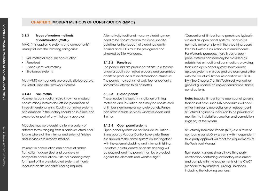
3.1.3 Types of modern methods of construction (MMC)MMC (this applies to systems and components)
usually fall into the following categories:
• Volumetric or modular construction
• Panelised
• Hybrid (semi-volumetric)
• Site-based systems
Most MMC components are usually site-based, e.g.
Insulated Concrete Formwork Systems.
3.1.3.1 volumetricVolumetric construction (also known as modular
construction) involves the ‘off-site’ production of
three-dimensional units. quality controlled systems
of production in the factory should be in place and
expected as part of any third-party approval.
Modules may be brought to site in a variety of
different forms, ranging from a basic structural shell
to one where all the internal and external finishes
and services are already installed.
Volumetric construction can consist of timber
frame, light gauge steel and concrete or
composite constructions. External cladding may
form part of the prefabricated system, with only
localised on-site specialist sealing required.
Alternatively, traditional masonry cladding may
need to be constructed; in this case, specific
detailing for the support of claddings, cavity
barriers and DPCs must be pre-agreed and
checked by Site Managers.
3.1.3.2 PanelisedThe panel units are produced ‘off-site’ in a factory
under a quality controlled process, and assembled
on-site to produce a three-dimensional structure.
The panels may consist of wall, floor or roof units,
sometimes referred to as cassettes.
3.1.3.3 Closed panelsThese involve the factory installation of lining
materials and insulation, and may be constructed
of timber, steel frame or concrete panels. Panels
can often include services, windows, doors and
finishes.
3.1.3.4 open panel systemsOpen panel systems do not include insulation,
lining boards, Vapour Control Layers, etc. These
are applied to the frame system on-site, together
with the external cladding and internal finishing.
Therefore, careful control of on-site finishing will
be required, and the panels must be protected
against the elements until weather tight.
‘Conventional’ timber frame panels are typically
classed as ‘open panel systems’, and would
normally arrive on-site with the sheathing board
fixed but without insulation or internal boards.
For Warranty purposes, these types of open
panel systems can normally be classified as
established or traditional construction, providing
that such open panel systems have quality
assured systems in place and are registered either
with the Structural Timber Association or TRADA
BM (See Chapter 7 of this Technical Manual for
general guidance on conventional timber frame
construction).
note: Bespoke timber frame open panel systems
that do not have such qA procedures will need
either third-party accreditation or independent
Structural Engineer supervision to be provided to
monitor the installation, erection and completion
(sign off) of the system.
Structurally Insulated Panels (SIPs) are a form of
composite panel. Only systems with independent
third-party approval will meet the requirements of
the Technical Manual.
Rain screen systems should have third-party
certification confirming satisfactory assessment,
and comply with the requirements of the CWCT
Standard for Systemised Building Envelopes,
including the following sections:
CHAPTER 3: MODERN METHODS OF CONSTRUCTION (MMC)CH
APTER 3: M
OD
ERN M
ETHO
DS O
F CO
NSTRU
CTIO
N (M
MC
)Te
ch
nic
al M
anu
al V
7: TS-011a-7.00-180814
CHAPTER 3
33
• Part 1: Scope, terminology, testing and
classification
• Part 2: Loadings, fixings and movement
• Part 3: Air, water and wind resistance
• Part 4: Operable components, additional
elements and means of access
• Part 5: Thermal, moisture and acoustic
performance
• Part 6: Fire performance
• Part 7: Robustness, durability, tolerances and
workmanship
• Part 8: Testing
3.1.3.5 HybridAgain off-site manufactured, this combines
both panelised and volumetric approaches,
and typically volumetric units, e.g. student
accommodation or hotel pods.
3.1.3.6 sub-assemblies and componentsThis category covers factory-built sub-assemblies
or components in an otherwise traditionally built
structural form, typically schemes incorporating
the use of floor or roof cassettes, precast concrete
foundation assemblies, preformed service
installations and cladding systems, etc.
3.1.3.7 site-based systemsThese are structural systems that fall outside
the ‘off-site manufactured’ categories, such as
Insulated Concrete Formwork (ICF). Only systems
with independent third-party approval will meet
the requirements of the Technical Manual. The
acceptability of these systems relies heavily on the
quality procedures in place for the installation of
the system on-site, in accordance with third-party
approval.
3.1.4 suitability of systems to meet Warranty requirements(Please also refer to the requirements in Chapter 2
of this Manual.)
An independent third-party assessment of the
system/product must recognise uk Building
Regulation requirements and our additional
Warranty standards.
Details of the performance and the limitations of
use of the material/product or system testing must
be provided to determine if the requirements of this
Manual are met.
The Independent Assessment, e.g. a European
Technical Assessment, must provide details of
performance and testing carried out in the
following areas to demonstrate acceptability to the
Warranty provider:
• Structural integrity
• Performance in fire situations
• Resistance to water penetration (consider
exposure rating of location), vapour
permeability and dangerous substances
• Safety in use
• Acoustic characteristics
• Thermal and movement characteristics
• Compatibility of materials (interaction between
components, structural or otherwise)
• Durability and longevity of materials (60-year
lifespan in accordance with CML requirements)
• Maintenance issues
Structural performance must be identified against
appropriate BS EN standards. The Developer must
provide actual structural calculations for each
project on a case-by-case basis, and the design
shall allow for robustness to disproportionate
collapse.
Where the independent certification does not
recognise our Warranty requirements, additional
checks may be required to confirm the system is
acceptable, e.g. the need to provide a drained
cavity behind some insulated cladding systems
and to external cladding systems on timber and
steel-framed systems. Supporting evidence of
testing undertaken to prove the system may be
asked for.

CHAPTER 3: MODERN METHODS OF CONSTRUCTION (MMC)CH
APTER 3: M
OD
ERN M
ETHO
DS O
F CO
NSTRU
CTIO
N (M
MC
)Te
ch
nic
al M
anu
al V
7: TS-011a-7.00-180814
Durability and weather tightness are key aspects of
the Technical Manual requirements, and the track
record of the MMC will need to be established.
Evidence of experience gained elsewhere, where
environmental conditions may be significantly
different, will need to be assessed, in comparison
with conditions here in the uk.
Treatment of timber components will need to be
assessed with regard to the species of timber used.
The natural durability and the need for preservative
treatment are dependent on the component’s
location in the construction and the Warranty
requirement for durability. Treatment for insect
attack in certain parts of the country will also be
required.
Detailing is critical in providing integrity to the
building, e.g. connections between a wall panel
and a window unit. Supporting documentation
must show the make-up of the tested system. When
assessing projects, a particular design detail may
not have been covered by the MMC certification,
e.g. a balcony junction. This information must be
made known at an early stage.
Certain components of a building have
particular functions and may not be replaced by
components that look similar but might structurally
behave in a different manner. Similarly, a product
with a third-party assessment for a particular use
may not be acceptable in a different form of
construction.
The continuation of quality Management Systems
from manufacture to erection on-site must be
demonstrated. The level of supervision of the
systems on-site is critical to meet the requirements
of this Technical Manual.
CH
APTER 4: SiTE in
vESTig
ATio
n REPo
RTS , gEo
log
y An
d C
on
TAm
inA
Tion
Tec
hn
ica
l ma
nua
l v7: TS-011a
-7.00-180814
CHAPTER 4
35
CHAPTer 4: siTe invesTigATion rePorTs, geoLogy AnD ConTAMinATion
ConTenTs
4.1 INTRODuCTION
4.2 ROLES AND RESPONSIBILITIES
4.3 FLOW CHART OF SITE INVESTIGATION PROCESS
4.4 PHASE 1: GEOENVIRONMENTAL ASSESSMENT (DESk STuDy)
4.5 PHASE 2: GEOENVIRONMENTAL ASSESSMENT (GROuND INVESTIGATION)
4.6 MAIN REFERENCES
APPenDix A CHECkLIST FOR GEOENVIRONMENTAL ASSESSMENT (PHASE 1 AND 2)
APPenDix B SOIL AND ROCk CLASSIFICATION
APPenDix C LABORATORy TESTING
Tec
hn
ica
l Ma
nua
l V6: TS-011a
-6.00-010413Te
ch
nic
al M
anu
al V
7: TS-011a-7.00-180814
FUNCTIONAL REQUIREMENTS
4. siTe invesTigATion rePorTs, geoLogy AnD ConTAMinATion
Workmanshipi. All work is to be carried out by a qualified and technically competent
person in a workmanlike manner.
Materialsi. All samples to be stored and kept in such a way that will not cause
inaccuracy when soils are tested.
Designi. The design and specifications shall provide a clear indication of the
design intent and demonstrate a satisfactory level of performance.
ii. The site investigation should be completed at an appropriate level for
the risk in accordance with the relevant British Standard.
iii. Site investigation and remedial measures must meet the relevant
Building Regulations, British Standards, Eurocodes and other statutory
requirements (refer to Appendix 2a for a list of standards referred to).
These functional requirements apply to the following sections of this chapter:
4.1 Introduction
4.2 Roles and Responsibilities
4.3 Flow Chart of Site Investigation Process
4.4 Phase 1: Geoenvironmental Assessment (Desk Study)
4.5 Phase 2: Geoenvironmental Assessment (Ground Investigation)
CHAPTER 4: SiTE invESTigATion REPoRTS, gEology And ConTAminATionCH
APTER 4: SiTE in
vESTig
ATio
n REPo
RTS , gEo
log
y An
d C
on
TAm
inA
Tion
Tec
hn
ica
l ma
nua
l v7: TS-011a
-7.00-180814
CHAPTER 4
37
4.1 inTroDuCTion
This Chapter sets out the requirements for an
acceptable site investigation. It is intended to
be flexible and user-friendly, and includes simple
checklists aimed at ensuring compliance. The aim
is to raise standards in the interests of both the
Warranty provider and the builder or Developer.
This will lead to a safe and economic design that
will minimise the risk to all those involved in the
project.
Where projects run over time and over budget, this
is usually as a direct result of problems within the
ground. It is therefore vitally important to reduce
the risk of unforeseen conditions that can directly
affect the overall cost of the project. It is believed
that builders and developers will view this work as
an important safeguard, rather than unnecessary
expenditure.
To ensure a consistently high standard, all stages
of the work should be carried out by a Chartered
Engineer or Chartered Geologist with at least five
years’ experience of this type of work. Specifying
properly qualified personnel will considerably
increase the overall industry standard.
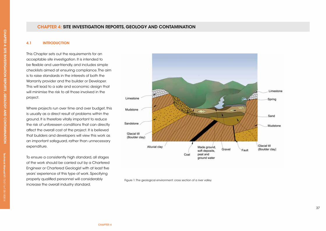
Figure 1: The geological environment: cross section of a river valley
CHAPTER 4: SiTE invESTigATion REPoRTS, gEology And ConTAminATionCH
APTER 4: SiTE in
vESTig
ATio
n REPo
RTS , gEo
log
y An
d C
on
TAm
inA
Tion
Tec
hn
ica
l ma
nua
l v7: TS-011a
-7.00-180814
4.2 roLes AnD resPonsiBiLiTies
The roles and responsibilities of those parties
involved in the development are the Owner,
Developer, Builder and Self-Builder.
4.2.1 owner/Developer/Builder/self BuilderThe provision of clear development proposals for the
site, and the implementation of a competent site
investigation using appropriately qualified personnel,
is now a priority for Regulators. These demonstrate
that any geotechnical and contaminated land risks
can be safely dealt with. Specific Health and Safety
responsibilities, in particular the CDM Regulations,
also require compliance.
4.2.2 environmental Health/Contaminated Land officerThe provision of advice to the local Planning
Department on technical matters and planning
conditions requires a competent and comprehensive
site investigation and associated risk assessment.
4.2.3 Local Authority Building ControlBuilding Control is responsible for enforcing
the Building Regulations, which also requires a
competent and comprehensive site investigation.
4.2.4 Health and safety executiveThe HSE are responsible for health and safety at
work, including the CDM Regulations.
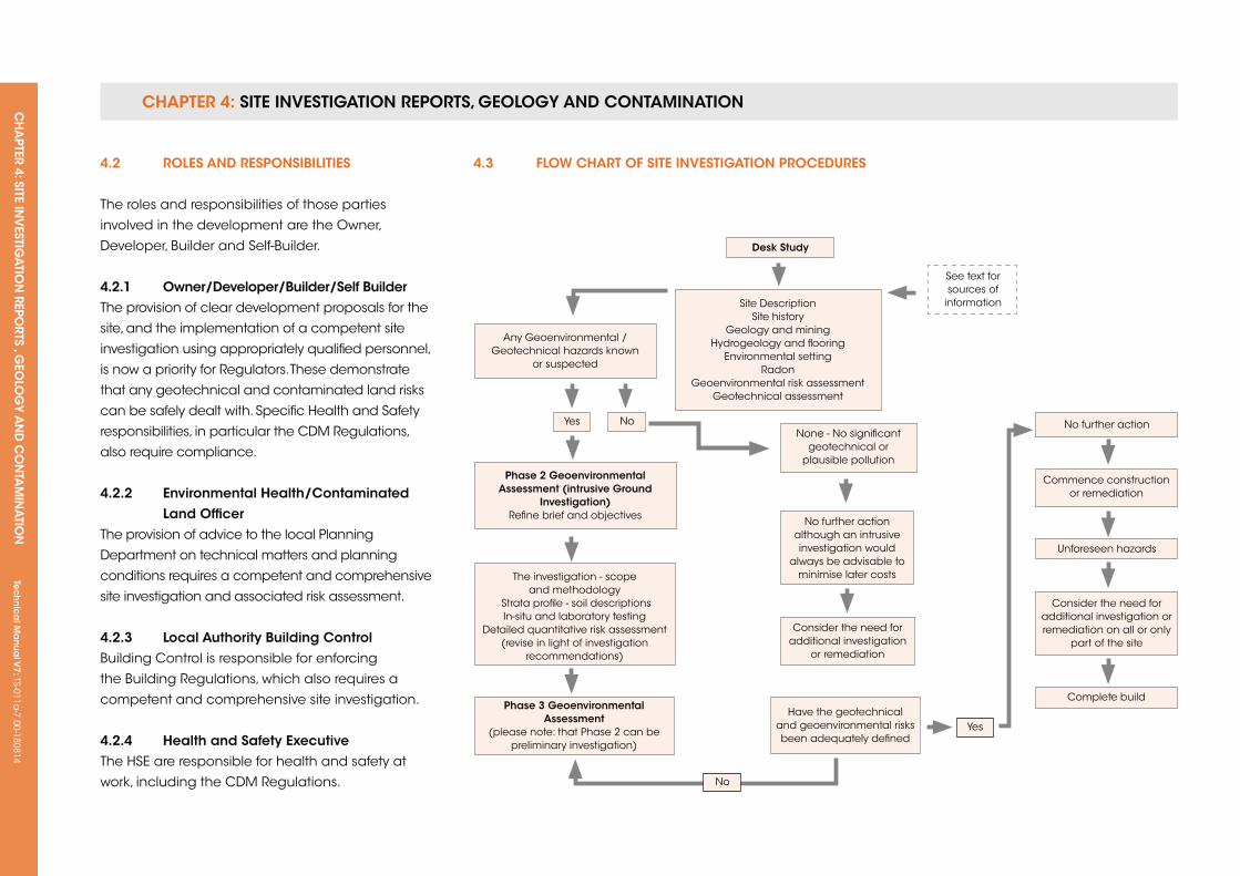
Desk study
yes
yes
No
No
Site Description Site history
Geology and mining Hydrogeology and flooring
Environmental setting Radon
Geoenvironmental risk assessment Geotechnical assessment
See text for sources of
information
None - No significant geotechnical or
plausible pollution
No further action although an intrusive investigation would
always be advisable to minimise later costs
Have the geotechnical and geoenvironmental risks been adequately defined
No further action
unforeseen hazards
Complete build
Commence construction or remediation
Consider the need for additional investigation or remediation on all or only
part of the site Consider the need for
additional investigation or remediation
Any Geoenvironmental / Geotechnical hazards known
or suspected
Phase 2 geoenvironmental Assessment (intrusive ground
investigation) Refine brief and objectives
The investigation - scope and methodology
Strata profile - soil descriptionsIn-situ and laboratory testing
Detailed quantitative risk assessment (revise in light of investigation
recommendations)
Phase 3 geoenvironmental Assessment
(please note: that Phase 2 can be preliminary investigation)
4.3 fLoW CHArT of siTe invesTigATion ProCeDures
CHAPTER 4: SiTE invESTigATion REPoRTS, gEology And ConTAminATionCH
APTER 4: SiTE in
vESTig
ATio
n REPo
RTS , gEo
log
y An
d C
on
TAm
inA
Tion
Tec
hn
ica
l ma
nua
l v7: TS-011a
-7.00-180814
CHAPTER 4
39
4.4 PHAse 1: geoenvironMenTAL AssessMenT (Desk sTuDy)
4.4.1 introductionThe aim of the Phase 1 Geoenvironmental
Assessment is to identify and assess the
potential geotechnical and geoenvironmental
(contamination) hazards on the site. Since all sites
are different, it is important to identify the scope
and purpose of the desk study. This will include
who commissioned the work, the development
proposals, the relevant procedures followed and
the objectives. Any issues specifically excluded
should also be noted if these might normally be
expected as part of the desk study.
4.4.2 site descriptionThe site description should define the exact extent
of the site, and should include a site address, grid
reference and elevation. The boundaries and
topography of the site should be defined.
A site inspection should always be carried out
not only of the site itself, but also the immediate
surrounding area. This should include any
information not apparent from the maps and
describe what currently occupies the site, such as
buildings, hard standing, watercourses, vegetation,
trees and any particular features.
The type and distribution of vegetation can
indicate soil and ground water conditions, and
note should be made of any invasive plants, such
as Japanese knotweed and Giant Hogweed.
Adjacent features and land use should be
reported if there is likely to be an impact on the
development. It is not uncommon for features such
as tanks to be known about but unrecorded.
The walkover should note any potential sources
of contamination and geotechnical hazards,
such as slopes, excavations, land slipping, ground
subsidence, soft ground or desiccated/shrinkable
soils.
All structures on the site should be inspected
both internally and externally for any evidence
of structural damage, such as tilting, cracking or
chemical attack. Any evidence of underground
features should be noted. Where practical, the
local residents can often give valuable information,
although caution should be used in respect of their
‘memories’. Local place names can give useful
indications of former uses, e.g. Gas Works Lane,
Water Lane, Tannery Road, etc. Aerial photographs
and their interpretation can also prove helpful.
A photographic record of the site, and any specific
features of the site, should be included with the
report.
4.4.3 site historyThe history of the site and the surrounding areas is
extremely important when assessing the likelihood
of contamination or geotechnical hazards.
Historical Ordnance Survey maps date back
to the mid-19th Century and often specify the
actual industrial use of particular sites or buildings.
They may show areas of quarrying or infilling,
and indicate where buried obstructions, such as
underground tanks or old foundations, can be
expected.
The influence or impact of off-site past industrial
use will depend upon the type of industry, the
underlying geology and the topography. However,
consideration should normally be given to any
such features within a 250m radius of the site (or
further where appropriate) with the potential to
affect it.
Historical maps are available from libraries and
commercial providers, such as GroundSure or
Envirocheck. The latter provide a cost-effective
method of obtaining maps, and include the
ability to superimpose current site boundaries on
older maps. Issues regarding possible breaches
of copyright are also avoided by using licensed
products.
It should be remembered that historical maps
only provide a snapshot in time, and care must be
CHAPTER 4: SiTE invESTigATion REPoRTS, gEology And ConTAminATionCH
APTER 4: SiTE in
vESTig
ATio
n REPo
RTS , gEo
log
y An
d C
on
TAm
inA
Tion
Tec
hn
ica
l ma
nua
l v7: TS-011a
-7.00-180814
taken when interpreting what may have occurred
in the intervening years. For example, a quarry may
be shown on one map and infilled on the next.
However, in the intervening period, it could have
expanded prior to infilling; similarly, industrial uses
may not always be recorded, while many military or
sensitive uses may have been omitted. Other sources
of information may include the ubiquitous internet
search and historical aerial photographs. Additionally,
it may be necessary to search the libraries of Local
Authorities and Local History departments.
4.4.4 geology and miningThe geology of the site should be recorded by
reference to published geological maps, which
most commonly exist at 1:50,000 (1 inch to 1
mile) and 1:10,000 (6 inch to 1 mile). The British
Geological Survey Geo-Index also provides existing
ground investigation records, including logs and
reports. It should be noted that these records
can relate not only to the surrounding areas but
may also include previous investigation of the
site itself. The information on the geological maps
can also be supplemented with British Geological
Survey technical reports, flood risk appraisals and
memoirs.
The bedrock geology, any overlying superficial
deposits and the effects of weathering should all
be described, together with any geological faults
that may affect the site. An explanation of the
likely ground conditions should be given, together
with reference to any other mapped geological
features, particularly if there are likely to be any
natural cavities or solution features.
4.4.4.1 Mining areasIn former coalfields, or other areas of mineral
extraction, the maps may not always record the
presence of old or active workings. The likelihood of
shallow coal workings affecting surface stability should
be established in conjunction with a Coal Authority
report. Such reports also record areas that have been
affected by the extraction of brine, which is particularly
prevalent in the Cheshire area. Other forms of mineral
extraction will require site-specific research.
The potential for mine workings and mine entries
within an influencing distance of the proposed
development should be addressed by a suitably
qualified and experienced engineer prior to
commencement of works, and in accordance with
CIRIA SP 32: Construction Over Abandoned Mine
Workings, 2002.
Reference should be made to reports on
geological hazards, such as Envirocheck or
GroundSure reports, both on-site and locally.
4.4.4.2 solution features in chalkSolution features (such as pipes, swallow holes and
solution cavities, sometimes loosely infilled with drift
deposits) are commonly found in chalk, caused by
water draining through the chalk and dissolving it.
The risk of solution features should be addressed
in the Site Investigation Report (commonly from an
Envirocheck or GroundSure report on geological
hazards, both on site and locally).
Hazard maps are available with different coloured
areas representing different levels of risk. Where the
risk is moderate or high, special precautions should
be taken, which for strip foundations would include
careful inspection of the excavation, probing and
use of reinforcement to span potential voids.
Where piled foundations are used, CIRIA PR 86
recommends “that a CPT (Cone Penetration
Test) is undertaken at each pile location at sites
identified during desk studies to be prone to
dissolution”. Alternatively, in some instances it can
be appropriate to design the pile for shaft friction
alone, assuming that the pile has no end bearing
due to a solution feature below it. In extreme
circumstances where a site investigation borehole
has encountered an extensive solution feature, the
shaft friction may also be reduced to take account
of this.
The potential effects of soakaways, leaking drains,
run off, etc. on the chalk will need to be considered
and addressed in the design.
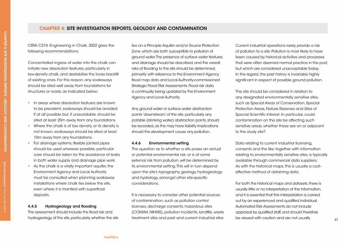
CHAPTER 4: SiTE invESTigATion REPoRTS, gEology And ConTAminATionCH
APTER 4: SiTE in
vESTig
ATio
n REPo
RTS , gEo
log
y An
d C
on
TAm
inA
Tion
Tec
hn
ica
l ma
nua
l v7: TS-011a
-7.00-180814
CHAPTER 4
41
CIRIA C574: Engineering in Chalk, 2002 gives the
following recommendations:
Concentrated ingress of water into the chalk can
initiate new dissolution features, particularly in
low-density chalk, and destabilise the loose backfill
of existing ones. For this reason, any soakaways
should be sited well away from foundations for
structures or roads, as indicated below:
• In areas where dissolution features are known
to be prevalent, soakaways should be avoided
if at all possible but, if unavoidable, should be
sited at least 20m away from any foundations
• Where the chalk is of low density, or its density is
not known, soakaways should be sited at least
10m away from any foundations.
• For drainage systems, flexible jointed pipes
should be used wherever possible; particular
care should be taken for the avoidance of leaks
in both water supply and drainage pipe work.
• As the chalk is a vitally important aquifer, the
Environment Agency and Local Authority
must be consulted when planning soakaway
installations where chalk lies below the site,
even where it is mantled with superficial
deposits.
4.4.5 Hydrogeology and floodingThe assessment should include the flood risk and
hydrogeology of the site, particularly whether the site
lies on a Principle Aquifer and/or Source Protection
Zone, which are both susceptible to pollution of
ground water. The presence of surface water features
and drainage should be described, and the overall
risks of flooding to the site should be determined,
primarily with reference to the Environment Agency
flood map data and Local Authority-commissioned
Strategic Flood Risk Assessments. Flood risk data
is continually being updated by the Environment
Agency and Local Authority.
Any ground water or surface water abstraction
points ‘downstream’ of the site, particularly any
potable (drinking water) abstraction points, should
be recorded, as this may have liability implications
should the development cause any pollution.
4.4.6 environmental settingThe question as to whether a site poses an actual
or potential environmental risk, or is at some
external risk from pollution, will be determined by
its environmental setting. This will in turn depend
upon the site’s topography, geology, hydrogeology
and hydrology, amongst other site-specific
considerations.
It is necessary to consider other potential sources
of contamination, such as pollution control
licenses, discharge consents, hazardous sites
(COMAH, NIHHIS), pollution incidents, landfills, waste
treatment sites and past and current industrial sites.
Current industrial operations rarely provide a risk
of pollution to a site. Pollution is most likely to have
been caused by historical activities and processes
that were often deemed normal practice in the past,
but which are considered unacceptable today.
In this regard, the past history is invariably highly
significant in respect of possible ground pollution.
The site should be considered in relation to
any designated environmentally sensitive sites,
such as Special Areas of Conservation, Special
Protection Areas, Nature Reserves and Sites of
Special Scientific Interest. In particular, could
contamination on the site be affecting such
sensitive areas, whether these are on or adjacent
to the study site?
Data relating to current industrial licensing,
consents and the like, together with information
relating to environmentally sensitive sites, is typically
available through commercial data suppliers.
As with the historical maps, this is usually a cost-
effective method of obtaining data.
For both the historical maps and datasets, there is
usually little or no interpretation of the information,
and it is essential that this interpretation is carried
out by an experienced and qualified individual.
Automated Risk Assessments do not include
appraisal by qualified staff, and should therefore
be viewed with caution and are not usually

CHAPTER 4: SiTE invESTigATion REPoRTS, gEology And ConTAminATionCH
APTER 4: SiTE in
vESTig
ATio
n REPo
RTS , gEo
log
y An
d C
on
TAm
inA
Tion
Tec
hn
ica
l ma
nua
l v7: TS-011a
-7.00-180814
acceptable to Regulators. An example of this was
a contaminated former petrol filling station site
recorded as having no past industrial use. The
historical maps never recorded the site as a filling
station, nor did the environmental data. However, the
walkover quickly identified former bases for pumps
and filling points for underground storage tanks
(uSTs).
4.4.7 radonThe need to incorporate Radon Protection
Measures should be determined by reference
to risk maps produced by the Health Protection
Agency. Such information is also usually included
within commercially available datasets.
4.4.8 geoenvironmental risk Assessment and conceptual site modelA quantitative health and environmental Risk
Assessment should be carried out as part of the
assessment. The process of Risk Assessment is set
out in Part IIA of the Environment Protection Act
1990 and amended in subsequent legislation.
This Act introduces the concept of a pollution
linkage; the linkage consists of a pollution
(contaminative) source or hazard and a receptor,
together with an established pathway between
the two. For land to be contaminated, a pollution
linkage (hazard-pathway-receptor) must exist - this
forms a so-called ‘conceptual model’ of the site.
Examples of pathways and the effects of land contamination (after PPS 23) are shown on Figure 2: Pathways
of potential contaminants.
sourCe PATHWAy reCePTor
Figure 2: Pathways of potential contaminants
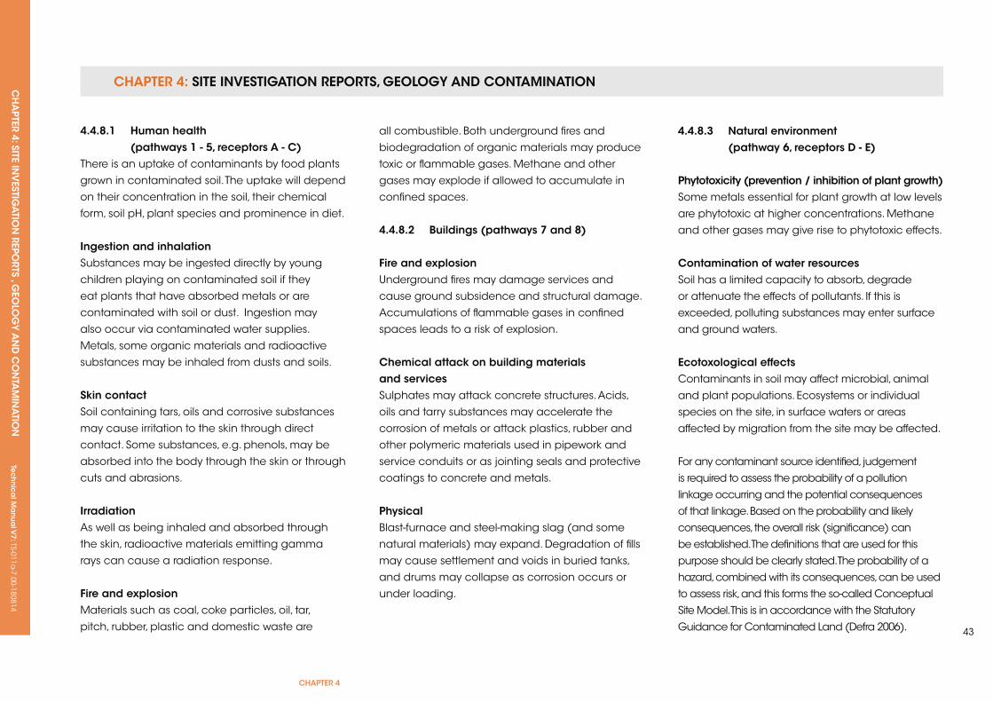
CHAPTER 4: SiTE invESTigATion REPoRTS, gEology And ConTAminATionCH
APTER 4: SiTE in
vESTig
ATio
n REPo
RTS , gEo
log
y An
d C
on
TAm
inA
Tion
Tec
hn
ica
l ma
nua
l v7: TS-011a
-7.00-180814
CHAPTER 4
43
4.4.8.1 Human health (pathways 1 - 5, receptors A - C)There is an uptake of contaminants by food plants
grown in contaminated soil. The uptake will depend
on their concentration in the soil, their chemical
form, soil pH, plant species and prominence in diet.
ingestion and inhalationSubstances may be ingested directly by young
children playing on contaminated soil if they
eat plants that have absorbed metals or are
contaminated with soil or dust. Ingestion may
also occur via contaminated water supplies.
Metals, some organic materials and radioactive
substances may be inhaled from dusts and soils.
skin contactSoil containing tars, oils and corrosive substances
may cause irritation to the skin through direct
contact. Some substances, e.g. phenols, may be
absorbed into the body through the skin or through
cuts and abrasions.
irradiation As well as being inhaled and absorbed through
the skin, radioactive materials emitting gamma
rays can cause a radiation response.
fire and explosionMaterials such as coal, coke particles, oil, tar,
pitch, rubber, plastic and domestic waste are
all combustible. Both underground fires and
biodegradation of organic materials may produce
toxic or flammable gases. Methane and other
gases may explode if allowed to accumulate in
confined spaces.
4.4.8.2 Buildings (pathways 7 and 8)
fire and explosionunderground fires may damage services and
cause ground subsidence and structural damage.
Accumulations of flammable gases in confined
spaces leads to a risk of explosion.
Chemical attack on building materials and servicesSulphates may attack concrete structures. Acids,
oils and tarry substances may accelerate the
corrosion of metals or attack plastics, rubber and
other polymeric materials used in pipework and
service conduits or as jointing seals and protective
coatings to concrete and metals.
Physical Blast-furnace and steel-making slag (and some
natural materials) may expand. Degradation of fills
may cause settlement and voids in buried tanks,
and drums may collapse as corrosion occurs or
under loading.
4.4.8.3 natural environment (pathway 6, receptors D - e)
Phytotoxicity (prevention / inhibition of plant growth)Some metals essential for plant growth at low levels
are phytotoxic at higher concentrations. Methane
and other gases may give rise to phytotoxic effects.
Contamination of water resources Soil has a limited capacity to absorb, degrade
or attenuate the effects of pollutants. If this is
exceeded, polluting substances may enter surface
and ground waters.
ecotoxological effectsContaminants in soil may affect microbial, animal
and plant populations. Ecosystems or individual
species on the site, in surface waters or areas
affected by migration from the site may be affected.
For any contaminant source identified, judgement
is required to assess the probability of a pollution
linkage occurring and the potential consequences
of that linkage. Based on the probability and likely
consequences, the overall risk (significance) can
be established. The definitions that are used for this
purpose should be clearly stated. The probability of a
hazard, combined with its consequences, can be used
to assess risk, and this forms the so-called Conceptual
Site Model. This is in accordance with the Statutory
Guidance for Contaminated Land (Defra 2006).
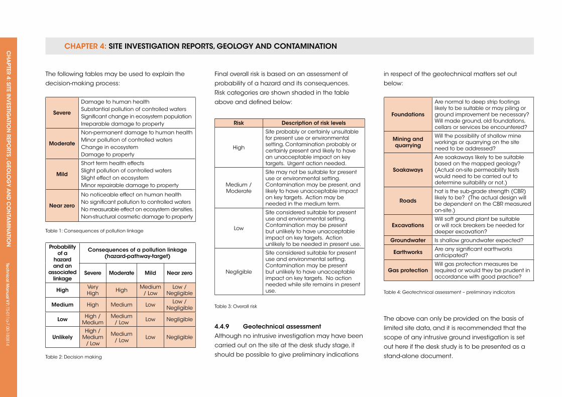
CHAPTER 4: SiTE invESTigATion REPoRTS, gEology And ConTAminATionCH
APTER 4: SiTE in
vESTig
ATio
n REPo
RTS , gEo
log
y An
d C
on
TAm
inA
Tion
Tec
hn
ica
l ma
nua
l v7: TS-011a
-7.00-180814
risk Description of risk levels
High
Site probably or certainly unsuitable for present use or environmental setting. Contamination probably or certainly present and likely to have an unacceptable impact on key targets. urgent action needed.
Medium / Moderate
Site may not be suitable for present use or environmental setting. Contamination may be present, and likely to have unacceptable impact on key targets. Action may be needed in the medium term.
Low
Site considered suitable for present use and environmental setting. Contamination may be present but unlikely to have unacceptable impact on key targets. Action unlikely to be needed in present use.
Negligible
Site considered suitable for present use and environmental setting. Contamination may be present but unlikely to have unacceptable impact on key targets. No action needed while site remains in present use.
Table 3: Overall risk
foundations
Are normal to deep strip footings likely to be suitable or may piling or ground improvement be necessary? Will made ground, old foundations, cellars or services be encountered?
Mining and quarrying
Will the possibility of shallow mine workings or quarrying on the site need to be addressed?
soakaways
Are soakaways likely to be suitable based on the mapped geology? (Actual on-site permeability tests would need to be carried out to determine suitability or not.)
roads
hat is the sub-grade strength (CBR) likely to be? (The actual design will be dependent on the CBR measured on-site.)
excavationsWill soft ground plant be suitable or will rock breakers be needed for deeper excavation?
groundwater Is shallow groundwater expected?
earthworks Are any significant earthworks anticipated?
gas protectionWill gas protection measures be required or would they be prudent in accordance with good practice?
Table 4: Geotechnical assessment – preliminary indicators
The following tables may be used to explain the
decision-making process:
severe
Damage to human healthSubstantial pollution of controlled watersSignificant change in ecosystem populationIrreparable damage to property
Moderate
Non-permanent damage to human healthMinor pollution of controlled watersChange in ecosystemDamage to property
Mild
Short term health effectsSlight pollution of controlled watersSlight effect on ecosystemMinor repairable damage to property
near zero
No noticeable effect on human healthNo significant pollution to controlled watersNo measurable effect on ecosystem densities.Non-structural cosmetic damage to property
Table 1: Consequences of pollution linkage
Final overall risk is based on an assessment of
probability of a hazard and its consequences.
Risk categories are shown shaded in the table
above and defined below:
4.4.9 geotechnical assessmentAlthough no intrusive investigation may have been
carried out on the site at the desk study stage, it
should be possible to give preliminary indications
Probability of a
hazard and an
associated linkage
Consequences of a pollution linkage (hazard-pathway-target)
severe Moderate Mild near zero
High Very High High Medium
/ LowLow /
Negligible
Medium High Medium Low Low / Negligible
Low High / Medium
Medium / Low Low Negligible
unlikelyHigh /
Medium/ Low
Medium / Low Low Negligible
Table 2: Decision making
in respect of the geotechnical matters set out
below:
The above can only be provided on the basis of
limited site data, and it is recommended that the
scope of any intrusive ground investigation is set
out here if the desk study is to be presented as a
stand-alone document.
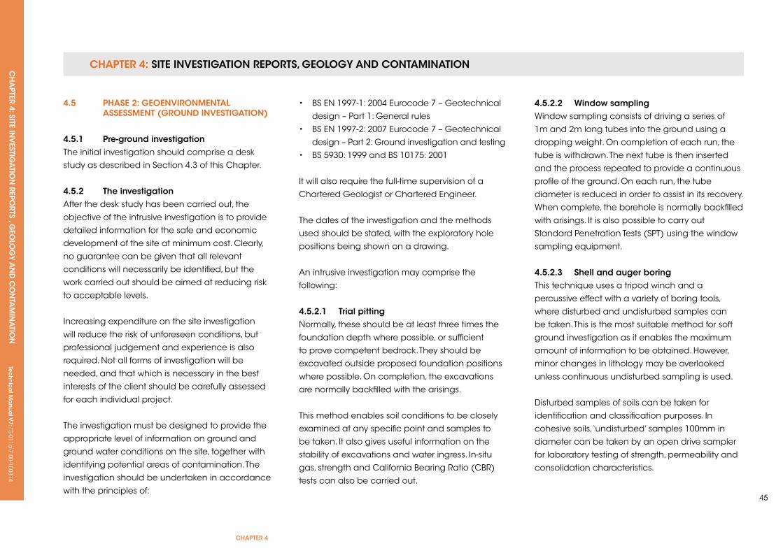
CHAPTER 4: SiTE invESTigATion REPoRTS, gEology And ConTAminATionCH
APTER 4: SiTE in
vESTig
ATio
n REPo
RTS , gEo
log
y An
d C
on
TAm
inA
Tion
Tec
hn
ica
l ma
nua
l v7: TS-011a
-7.00-180814
CHAPTER 4
45
4.5 PHAse 2: geoenvironMenTAL AssessMenT (grounD invesTigATion)
4.5.1 Pre-ground investigation The initial investigation should comprise a desk
study as described in Section 4.3 of this Chapter.
4.5.2 The investigationAfter the desk study has been carried out, the
objective of the intrusive investigation is to provide
detailed information for the safe and economic
development of the site at minimum cost. Clearly,
no guarantee can be given that all relevant
conditions will necessarily be identified, but the
work carried out should be aimed at reducing risk
to acceptable levels.
Increasing expenditure on the site investigation
will reduce the risk of unforeseen conditions, but
professional judgement and experience is also
required. Not all forms of investigation will be
needed, and that which is necessary in the best
interests of the client should be carefully assessed
for each individual project.
The investigation must be designed to provide the
appropriate level of information on ground and
ground water conditions on the site, together with
identifying potential areas of contamination. The
investigation should be undertaken in accordance
with the principles of:
• BS EN 1997-1: 2004 Eurocode 7 – Geotechnical
design – Part 1: General rules
• BS EN 1997-2: 2007 Eurocode 7 – Geotechnical
design – Part 2: Ground investigation and testing
• BS 5930: 1999 and BS 10175: 2001
It will also require the full-time supervision of a
Chartered Geologist or Chartered Engineer.
The dates of the investigation and the methods
used should be stated, with the exploratory hole
positions being shown on a drawing.
An intrusive investigation may comprise the
following:
4.5.2.1 Trial pittingNormally, these should be at least three times the
foundation depth where possible, or sufficient
to prove competent bedrock. They should be
excavated outside proposed foundation positions
where possible. On completion, the excavations
are normally backfilled with the arisings.
This method enables soil conditions to be closely
examined at any specific point and samples to
be taken. It also gives useful information on the
stability of excavations and water ingress. In-situ
gas, strength and California Bearing Ratio (CBR)
tests can also be carried out.
4.5.2.2 Window samplingWindow sampling consists of driving a series of
1m and 2m long tubes into the ground using a
dropping weight. On completion of each run, the
tube is withdrawn. The next tube is then inserted
and the process repeated to provide a continuous
profile of the ground. On each run, the tube
diameter is reduced in order to assist in its recovery.
When complete, the borehole is normally backfilled
with arisings. It is also possible to carry out
Standard Penetration Tests (SPT) using the window
sampling equipment.
4.5.2.3 shell and auger boringThis technique uses a tripod winch and a
percussive effect with a variety of boring tools,
where disturbed and undisturbed samples can
be taken. This is the most suitable method for soft
ground investigation as it enables the maximum
amount of information to be obtained. However,
minor changes in lithology may be overlooked
unless continuous undisturbed sampling is used.
Disturbed samples of soils can be taken for
identification and classification purposes. In
cohesive soils, ‘undisturbed’ samples 100mm in
diameter can be taken by an open drive sampler
for laboratory testing of strength, permeability and
consolidation characteristics.
CHAPTER 4: SiTE invESTigATion REPoRTS, gEology And ConTAminATionCH
APTER 4: SiTE in
vESTig
ATio
n REPo
RTS , gEo
log
y An
d C
on
TAm
inA
Tion
Tec
hn
ica
l ma
nua
l v7: TS-011a
-7.00-180814
SPT are used in granular and cohesive materials
and in soft or weathered rocks. The resulting ‘N’
value can be compared to empirical data on
strength and relative density. Difficulties in obtaining
true ‘N’ values mean they should only be used as a
guide, and not as an absolute value in foundation
design.
4.5.2.4 rotary drillingTwo main types of rotary drilling can be carried out
in rock. Rock coring using a diamond or tungsten
carbide-tipped core bit provides samples and
information on rock types, fissuring and weathering.
Open-hole drilling only produces small particles
for identification purposes, and the information
gained is therefore limited. The latter is, however,
useful as a quick method of detecting major strata
changes and the location of coal seams and old
workings. Water, air, foam or drilling muds may be
used as the flushing medium in either case.
Rotary open-hole drilling is carried out to determine
the existence of any voids or broken ground that
could affect surface stability. Due to the risk of
combustion, the drilling is normally done using
a water flush. On completion, the boreholes are
backfilled with bentonite cement. A Coal Authority
Licence is required in advance of any exploratory
work intended to investigate possible coal
workings.
4.5.2.5 geophysicsGeophysics can be used in certain situations and
is useful where significant anomalies exist in the
ground. Ground-penetrating radar is probably the
most common for defining near-surface features.
The results from geophysics can be variable and,
combined with the relative high cost, should be
used advisedly.
4.5.3 strata profileFull strata descriptions should be given based on
visual identification and in accordance with the
requirements of:
• BS EN ISO 14688-1: 2002 Geotechnical
investigation and testing – Identification and
classification of soil – Part 1
• BS EN ISO 14688-2: 2004 Geotechnical
investigation and testing – Identification and
classification of soil – Part 2
• BS EN ISO 14689-1: 2003 Geotechnical
investigation and testing – Identification and
classification of rock – Part 1
4.5.4 soil descriptionSamples from boreholes or trial pits should be fully
described in accordance with the latest guidance
from the British Standards and Eurocodes. They
should include colour, consistency, structure,
weathering, lithological type, inclusions and origin.
All descriptions should be based on visual and
manual identification as per recognised descriptive
methods. The methodology for soil and rock
description is given in more detail in Appendix B.
4.5.5 in-situ and laboratory testing
4.5.5.1 in-situ gas monitoringMethane is the dominant constituent of landfill
gas, and can form an explosive mixture in air at
concentrations of between 5% and 15%. Thus, 5%
methane in air is known as the Lower Explosive
Limit (LEL). Concentrations less than this do not
normally ignite. Carbon dioxide can also be a
potential problem, especially where it occurs in
concentrations greater than 1.5%.
In-situ gas tests should be carried out in the
boreholes on completion, and in probe holes
made in the sides of the trial pits. Testing is with a
portable meter that measures the methane content
as its percentage volume in air. The corresponding
oxygen and carbon dioxide concentrations are
also measured. Care is needed with this, since the
rapid mixing and dilution of any gases within the
atmosphere can occur very quickly.
A more accurate method used to monitor over the
longer term consists of gas monitoring standpipes
installed in boreholes. These typically comprise
slotted uPVC pipework surrounded by single sized
gravel. The top 0.5m to 1m of pipework is usually
CHAPTER 4: SiTE invESTigATion REPoRTS, gEology And ConTAminATionCH
APTER 4: SiTE in
vESTig
ATio
n REPo
RTS , gEo
log
y An
d C
on
TAm
inA
Tion
Tec
hn
ica
l ma
nua
l v7: TS-011a
-7.00-180814
CHAPTER 4
47
not slotted and is surrounded by bentonite pellets
to seal the borehole. Valves are fitted and the
installations protected by lockable stopcock covers
normally fitted flush with the ground. Monitoring is
again with a portable meter and is usually done
on a fortnightly or monthly basis, with at least six
visits being appropriate for most sites.
The risks associated with the gases should be
considered in accordance with documents
such as:
• BS 8485: 2007 Code of Practice for the
characterisation and remediation from ground
gas in affected developments
• CIRIA Report C665 Assessing risks posed by
hazardous ground gases to buildings
• NHBC Report No. 4 Guidance on evaluation of
development proposals on sites here methane
and carbon dioxide are present
4.5.5.2 in-situ strength testingHand vane and MExE cone penetrometer tests
can be carried out in trial pits in order to assess the
strengths and CBR values of made ground, soils
and heavily weathered bedrock materials.
4.5.5.3 soakaway testingIf sustainable drainage is being considered,
soakaway testing should be carried out. This
is preferably done in trial pits, with the aim of
intersecting permeable soils or naturally occurring
fissures within bedrock.
Soakaway testing involves filling the trial pits with
water from a bowser or such like, and measuring
the fall in water over time. Where possible, two
tests should be carried out to allow the immediate
surrounding ground to become saturated.
By knowing the dimensions of the trial pit, the
permeability and/or rate of dissipation can be
calculated.
Soakaway test results obtained from small
hand-dug pits or shallow boreholes should be
treated with caution.
4.5.5.4 geotechnical laboratory testingSoil testing should be carried out to BS 1377:
1990 Methods of test for soils for civil engineering
purposes, and the laboratory used should be
recorded and conducted by an approved ukAS
laboratory. Normally, the results are summarised
and the full results appended; a summary of the
main types of test is presented in Appendix C.
4.5.5.5 Contamination laboratory testingAs with the investigation, the sampling should be
under the full-time direction of either a Chartered
Engineer or Chartered Geologist. All the recovered
soil samples should be screened on-site for any
visual or olfactory evidence of contamination,
including the presence of Volatile Organic
Compounds (VOCs). Samples should be selected
from the trial pits and boreholes based on those
most likely to be contaminated, and those that
will give the most appropriate indication of the
spread of any contaminants. The samples should
be stored in either glass or plastic containers
and where necessary kept in cooled conditions.
Testing should be carried out by a ukAS accredited
laboratory, in accordance with the Environment
Agency’s Monitoring Certification Scheme; MCERTS
performance standards.
The aim of this is to make a preliminary assessment
of the level of any contamination on the site, in
order to determine if there are any significant risks
associated with contaminants in respect of both
human health and the environment, including
controlled waters. In addition to the soil, ground
water samples should be tested where appropriate.
4.5.6 geoenvironmental risk Assessment (conceptual site model)The qualitative health and environmental risk
assessment carried out as part of the desk study
should be revised, based on the findings of
the ground investigation and the results of the
contamination testing, to produce a Detailed
quantitative Risk Assessment (DqRA).
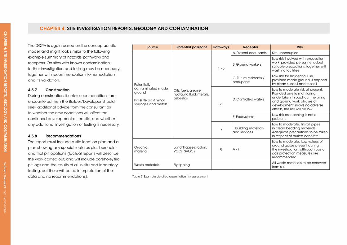
CHAPTER 4: SiTE invESTigATion REPoRTS, gEology And ConTAminATionCH
APTER 4: SiTE in
vESTig
ATio
n REPo
RTS , gEo
log
y An
d C
on
TAm
inA
Tion
Tec
hn
ica
l ma
nua
l v7: TS-011a
-7.00-180814
source Potential pollutant Pathways receptor risk
Potentially contaminated made ground
Possible past minor spillages and metals
Oils, fuels, grease, hydraulic fluid, metals, asbestos
1 - 5
A. Present occupants Site unoccupied
B. Ground workers
Low risk involved with excavation work, provided personnel adopt suitable precautions, together with washing facilities
C. Future residents / occupants
Low risk for residential use, provided made ground is capped by clean subsoil and topsoil
6D. Controlled waters
Low to moderate risk at present. Provided on-site monitoring undertaken throughout the piling and ground work phases of development shows no adverse effects, the risk will be low
E. Ecosystems Low risk as leaching is not a problem
7 F. Building materials and services
Low to moderate. Install pipes in clean bedding materials. Adequate precautions to be taken in respect of buried concrete
Organic material
Landfill gases, radon, VOCs, SVOCs 8 A - F
Low to moderate. Low values of ground gases present during the investigation, although basic gas protection measures are recommended
Waste materials Fly-tipping All waste materials to be removed from site
Table 5: Example detailed quantitative risk assessment
The DqRA is again based on the conceptual site
model, and might look similar to the following
example summary of hazards, pathways and
receptors. On sites with known contamination,
further investigation and testing may be necessary,
together with recommendations for remediation
and its validation.
4.5.7 ConstructionDuring construction, if unforeseen conditions are
encountered then the Builder/Developer should
seek additional advice from the consultant as
to whether the new conditions will affect the
continued development of the site, and whether
any additional investigation or testing is necessary.
4.5.8 recommendationsThe report must include a site location plan and a
plan showing any special features plus borehole
and trial pit locations (factual reports will describe
the work carried out, and will include borehole/trial
pit logs and the results of all in-situ and laboratory
testing, but there will be no interpretation of the
data and no recommendations).
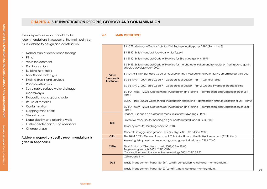
CHAPTER 4: SiTE invESTigATion REPoRTS, gEology And ConTAminATionCH
APTER 4: SiTE in
vESTig
ATio
n REPo
RTS , gEo
log
y An
d C
on
TAm
inA
Tion
Tec
hn
ica
l ma
nua
l v7: TS-011a
-7.00-180814
CHAPTER 4
49
British standards institution
BS 1377: Methods of Test for Soils for Civil Engineering Purposes 1990 (Parts 1 to 8)
BS 3882: British Standard Specification for Topsoil
BS 5930: British Standard Code of Practice for Site Investigations, 1999
BS 8485: British Standard Code of Practice for the characterisation and remediation from ground gas in affected developments, 2007
BS 10175: British Standard Code of Practice for the Investigation of Potentially Contaminated Sites, 2001
BS EN 1997-1: 2004 ‘Euro-Code 7 – Geotechnical Design – Part 1: General Rules’
BS EN 1997-2: 2007 ‘Euro-Code 7 – Geotechnical Design – Part 2: Ground Investigation and Testing’
BS ISO 14688-1: 2002 ‘Geotechnical Investigation and Testing – Identification and Classification of Soil – Part 1’
BS ISO 14688-2: 2004 ‘Geotechnical Investigation and Testing – Identification and Classification of Soil – Part 2’
BS ISO 14689-1: 2003 ‘Geotechnical Investigation and Testing – Identification and Classification of Rock – Part 1’
Bre
Radon: Guidance on protective measures for new dwellings, BR 211
Protective measures for housing on gas-contaminated land, BR 414, 2001
Cover systems for land regeneration, 2004
Concrete in aggressive ground. Special Digest SD1, 3rd Edition, 2005
CieH The LqM / CIEH Generic Assessment Criteria for Human Health Risk Assessment (2nd Edition)
CiriA
Assessing risks posed by hazardous ground gases to buildings, CIRIA C665 Shaft friction of CFA piles in chalk 2003, CIRIA PR 86Engineering in chalk 2002, CIRIA C574Construction over abandoned mine workings 2002, CIRIA SP 32
Doe
CLR reports 1 - 4
Waste Management Paper No. 26A ‘Landfill completion: A technical memorandum…’
Waste Management Paper No. 27 ‘Landfill Gas: A technical memorandum…’
The interpretative report should make
recommendations in respect of the main points or
issues related to design and construction:
• Normal strip or deep trench footings
• Piling
• Vibro replacement
• Raft foundation
• Building near trees
• Landfill and radon gas
• Existing drains and services
• Road construction
• Sustainable surface water drainage
(soakaways)
• Excavations and ground water
• Reuse of materials
• Contamination
• Capping mine shafts
• Site soil reuse
• Slope stability and retaining walls
• Further geotechnical considerations
• Change of use
Advice in respect of specific recommendations is given in Appendix A.
4.6 MAin referenCes
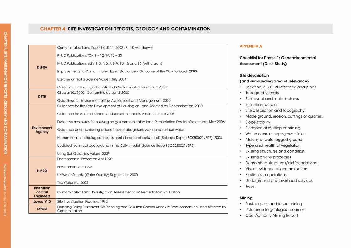
CHAPTER 4: SiTE invESTigATion REPoRTS, gEology And ConTAminATionCH
APTER 4: SiTE in
vESTig
ATio
n REPo
RTS , gEo
log
y An
d C
on
TAm
inA
Tion
Tec
hn
ica
l ma
nua
l v7: TS-011a
-7.00-180814
DefrA
Contaminated Land Report CLR 11, 2002 (7 - 10 withdrawn)
R & D Publications TOx 1 – 12, 14, 16 – 25
R & D Publications SGV 1, 3, 4, 5, 7, 8, 9, 10, 15 and 16 (withdrawn)
Improvements to Contaminated Land Guidance - ‘Outcome of the Way Forward’, 2008
Exercise on Soil Guideline Values. July 2008
Guidance on the Legal Definition of Contaminated Land. July 2008
DeTrCircular 02/2000. Contaminated Land, 2000
Guidelines for Environmental Risk Assessment and Management, 2000
environment Agency
Guidance for the Safe Development of Housing on Land Affected by Contamination, 2000
Guidance for waste destined for disposal in landfills, Version 2, June 2006
Protective measures for housing on gas-contaminated land Remediation Position Statements, May 2006
Guidance and monitoring of landfill leachate, groundwater and surface water
Human health toxicological assessment of contaminants in soil (Science Report SC050021/SR2), 2008
updated technical background in the CLEA model (Science Report SC0520021/SR3)
using Soil Guideline Values, 2009
HMso
Environmental Protection Act 1990
Environment Act 1995
uk Water Supply (Water quality) Regulations 2000
The Water Act 2003
institution of Civil
engineersContaminated Land: Investigation, Assessment and Remediation, 2nd Edition
Joyce M D Site Investigation Practice, 1982
oPDM Planning Policy Statement 23: Planning and Pollution Control Annex 2: Development on Land Affected by Contamination
APPenDix A
Checklist for Phase 1: geoenvironmental Assessment (Desk study)
site description (and surrounding area of relevance)• Location, o.S. Grid reference and plans
• Topography, levels
• Site layout and main features
• Site infrastructure
• Site description and topography
• Made ground, erosion, cuttings or quarries
• Slope stability
• Evidence of faulting or mining
• Watercourses, seepages or sinks
• Marshy or waterlogged ground
• Type and health of vegetation
• Existing structures and condition
• Existing on-site processes
• Demolished structures/old foundations
• Visual evidence of contamination
• Existing site operations
• underground and overhead services
• Trees
Mining• Past, present and future mining
• Reference to geological sources
• Coal Authority Mining Report
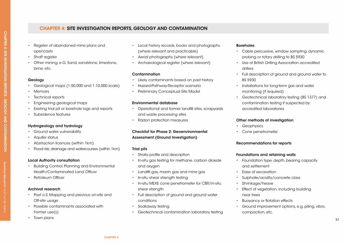
CHAPTER 4: SiTE invESTigATion REPoRTS, gEology And ConTAminATionCH
APTER 4: SiTE in
vESTig
ATio
n REPo
RTS , gEo
log
y An
d C
on
TAm
inA
Tion
Tec
hn
ica
l ma
nua
l v7: TS-011a
-7.00-180814
CHAPTER 4
51
• Register of abandoned mine plans and
opencasts
• Shaft register
• Other mining, e.G. Sand, sandstone, limestone,
brine, etc.
geology• Geological maps (1:50,000 and 1:10,000 scale)
• Memoirs
• Technical reports
• Engineering geological maps
• Existing trial pit or borehole logs and reports
• Subsidence features
Hydrogeology and hydrology• Ground water vulnerability
• Aquifer status
• Abstraction licences (within 1km)
• Flood risk, drainage and watercourses (within 1km)
Local Authority consultation• Building Control, Planning and Environmental
Health/Contaminated Land Officer
• Petroleum Officer
Archival research• Past o.S. Mapping and previous on-site and
Off-site usage
• Possible contaminants associated with
Former use(s)
• Town plans
• Local history records, books and photographs
(where relevant and practicable)
• Aerial photographs (where relevant)
• Archaeological register (where relevant)
Contamination• Likely contaminants based on past history
• Hazard-Pathway-Receptor scenario
• Preliminary Conceptual Site Model
environmental database• Operational and former landfill sites, scrapyards
and waste processing sites
• Radon protection measures
Checklist for Phase 2: geoenvironmental Assessment (ground investigation)
Trial pits• Strata profile and description
• In-situ gas testing for methane, carbon dioxide
and oxygen
• Landfill gas, marsh gas and mine gas
• In-situ shear strength testing
• In-situ MExE cone penetrometer for CBR/in-situ
shear strength
• Full description of ground and ground water
conditions
• Soakaway testing
• Geotechnical contamination laboratory testing
Boreholes• Cable percussive, window sampling, dynamic
probing or rotary drilling to BS 5930
• use of British Drilling Association accredited
drillers
• Full description of ground and ground water to
BS 5930
• Installations for long-term gas and water
monitoring (if required)
• Geotechnical laboratory testing (BS 1377) and
contamination testing if suspected by
accredited laboratories
other methods of investigation• Geophysics
• Cone penetrometer
recommendations for reports
foundations and retaining walls• Foundation type, depth, bearing capacity
and settlement
• Ease of excavation
• Sulphate/acidity/concrete class
• Shrinkage/heave
• Effect of vegetation, including building
near trees
• Buoyancy or flotation effects
• Ground improvement options, e.g. piling, vibro,
compaction, etc.
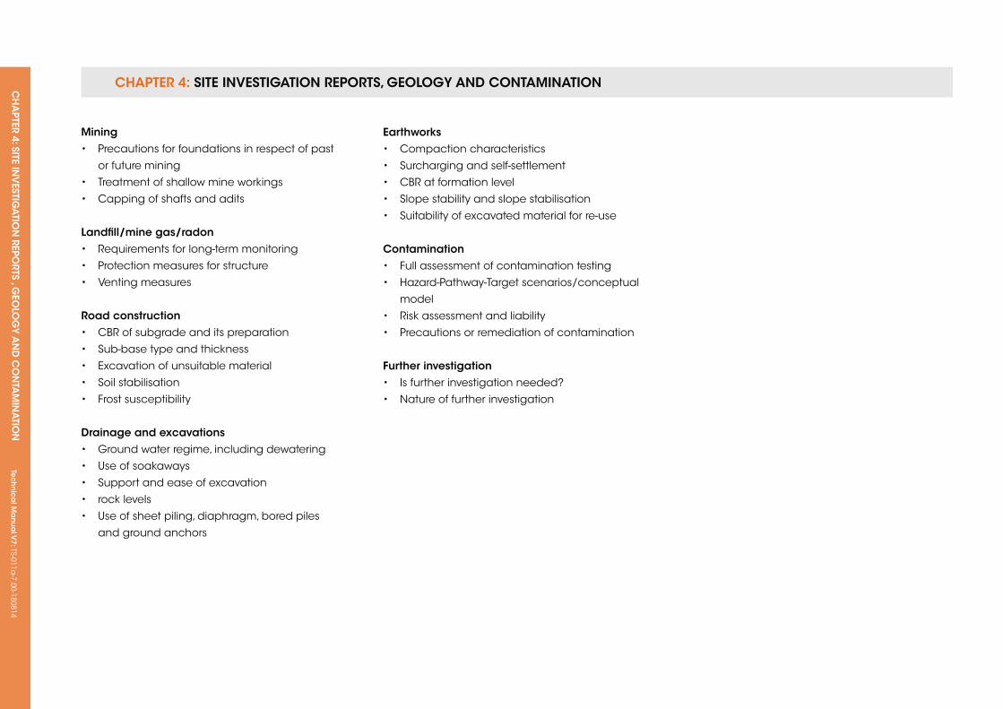
CHAPTER 4: SiTE invESTigATion REPoRTS, gEology And ConTAminATionCH
APTER 4: SiTE in
vESTig
ATio
n REPo
RTS , gEo
log
y An
d C
on
TAm
inA
Tion
Tec
hn
ica
l ma
nua
l v7: TS-011a
-7.00-180814
Mining• Precautions for foundations in respect of past
or future mining
• Treatment of shallow mine workings
• Capping of shafts and adits
Landfill/mine gas/radon• Requirements for long-term monitoring
• Protection measures for structure
• Venting measures
road construction• CBR of subgrade and its preparation
• Sub-base type and thickness
• Excavation of unsuitable material
• Soil stabilisation
• Frost susceptibility
Drainage and excavations• Ground water regime, including dewatering
• use of soakaways
• Support and ease of excavation
• rock levels
• use of sheet piling, diaphragm, bored piles
and ground anchors
earthworks• Compaction characteristics
• Surcharging and self-settlement
• CBR at formation level
• Slope stability and slope stabilisation
• Suitability of excavated material for re-use
Contamination• Full assessment of contamination testing
• Hazard-Pathway-Target scenarios/conceptual
model
• Risk assessment and liability
• Precautions or remediation of contamination
further investigation• Is further investigation needed?
• Nature of further investigation
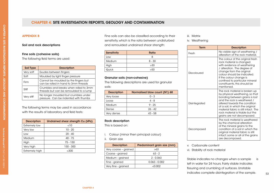
CHAPTER 4: SiTE invESTigATion REPoRTS, gEology And ConTAminATionCH
APTER 4: SiTE in
vESTig
ATio
n REPo
RTS , gEo
log
y An
d C
on
TAm
inA
Tion
Tec
hn
ica
l ma
nua
l v7: TS-011a
-7.00-180814
CHAPTER 4
53
soil Type Description
Very soft Exudes between fingers
Soft Moulded by light finger pressure
Firm Cannot be moulded by the fingers but can be rolled in hand to 3mm threads
Stiff Crumbles and breaks when rolled to 3mm threads but can be remoulded to a lump
Very stiff No longer moulded but crumbles under pressure. Can be indented with thumbs
Description undrained shear strength Cu (kPa)
Extremely low <10
Very low 10 - 20
Low 20 - 40
Medium 40 - 75
High 75 - 150
Very high 150 - 300
Extremely high >300
sensitivity ratio
Low 8
Medium 8 - 30
High >30
quick >50
Description normalised blow count (n1) 60
Very loose 0 - 3
Loose 4 - 8
Medium 9 - 25
Dense 26 - 42
Very dense 43 - 58
Description Predominant grain size (mm)
Very coarse – grained >63
Coarse - grained 63 - 2
Medium - grained 2 - 0.063
Fine - grained 0.063 - 0.002
Very fine - grained <0.002
Term Description
Fresh No visible sign of weathering /alteration of the rock material.
Discoloured
The colour of the original fresh rock material is changed with evidence of weathering / alteration. The degree of change from the original colour should be indicated. If the colour change is confined to particular mineral constituents, this should be mentioned.
Disintegrated
The rock material is broken up by physical weathering, so that bonding between grains is lost and the rock is weathered /altered towards the condition of a soil, in which the original material fabric is still intact. The rock material is friable but the grains are not decomposed.
Decomposed
The rock material is weathered by the chemical alteration of the mineral grains to the condition of a soil in which the original material fabric is still intact; some or all of the grains are decomposed.
APPenDix B
soil and rock descriptions
fine soils (cohesive soils)The following field terms are used:
The following terms may be used in accordance
with the results of laboratory and field tests:
Fine soils can also be classified according to their
sensitivity, which is the ratio between undisturbed
and remoulded undrained shear strength:
granular soils (non-cohesive)The following descriptions are used for granular
soils:
rock descriptionThis is based on:
i. Colour (minor then principal colour)
ii. Grain size
iii. Matrix
iv. Weathering
v. Carbonate content
vi. Stability of rock material
Stable indicates no changes when a sample is
left in water for 24 hours. Fairly stable indicates
fissuring and crumbling of surfaces. unstable
indicates complete disintegration of the sample.

CHAPTER 4: SiTE invESTigATion REPoRTS, gEology And ConTAminATionCH
APTER 4: SiTE in
vESTig
ATio
n REPo
RTS , gEo
log
y An
d C
on
TAm
inA
Tion
Tec
hn
ica
l ma
nua
l v7: TS-011a
-7.00-180814
Term field identification
unconfined Compressive
strength (MPa)
Extremely weak (a) Indented by thumbnail Less than 1
Very weak
Crumbles under firm blows with point of geological hammer, can be peeled by a pocket knife
2 - 5
Weak
Can be peeled by a pocket knife with difficulty, shallow indentations made by firm blow with point of geological hammer
6 - 25
Medium strong
Cannot be scraped or peeled with a pocket knife, specimen can be fractured with single firm blow of geological hammer
26 - 50
StrongSpecimen required more than one blow of geological hammer to fracture it
51 - 100
Very strong
Specimen requires many blows of geological hammer to fracture it
101 - 250
Extremely strong
Specimen can only be chipped with geological hammer
Greater than 250
note:
(a) Some extremely weak rocks will behave as soils and should be described as soils.
Term Description grades
Fresh No visible sign of rock material weathering; perhaps slight discolouration on major discontinuity surfaces 0
Slightly weathered Discolouration indicates weathering of rock material and discontinuity surfaces 1
Moderately weathered
Less than half of the rock material is decomposed or disintegrated. Fresh or discoloured rock is present either as a continuous framework or as core stones 2
Highly weathered
More than half of the rock material is decomposed or disintegrated. Fresh or discoloured rock is present either as a continuous framework or as core stones 3
Completely weathered
All rock material is decomposed and/or disintegrated to soil. The original mass structure is still largely intact 4
Residual soil All rock material is converted to soil. The mass structure and material fabric are destroyed. There is a large change in volume, but the soils have not been significantly transported 5
sedimentary Metamorphic igneous
Bedded Cleaved Massive
Interbedded Foliated Flowbanded
Laminated Schistose Folded
Folded Banded Lineated
Massive Lineated
Graded Gneissose
Folded
vii. unconfined compressive strength viii. Structure
ix. Discontinuities
x. Discontinuity spacing, persistence and
roughness, infilling and seepage
xi. Weathering of the rock mass
xii. Rock mass permeability
In addition to the description of the soils and rocks
and their associated depth, ground water should
be noted in terms of both where it was struck and
changes over time. Any unusual colouration or
odours of any of the soils encountered during the
investigation should be recorded.
It should be noted that lateral and vertical
changes can occur between exploratory points,
and care is needed when extrapolation is used.
This is particularly true of the ‘made ground’, which,
by its nature, can be highly variable in its physical
and chemical composition.
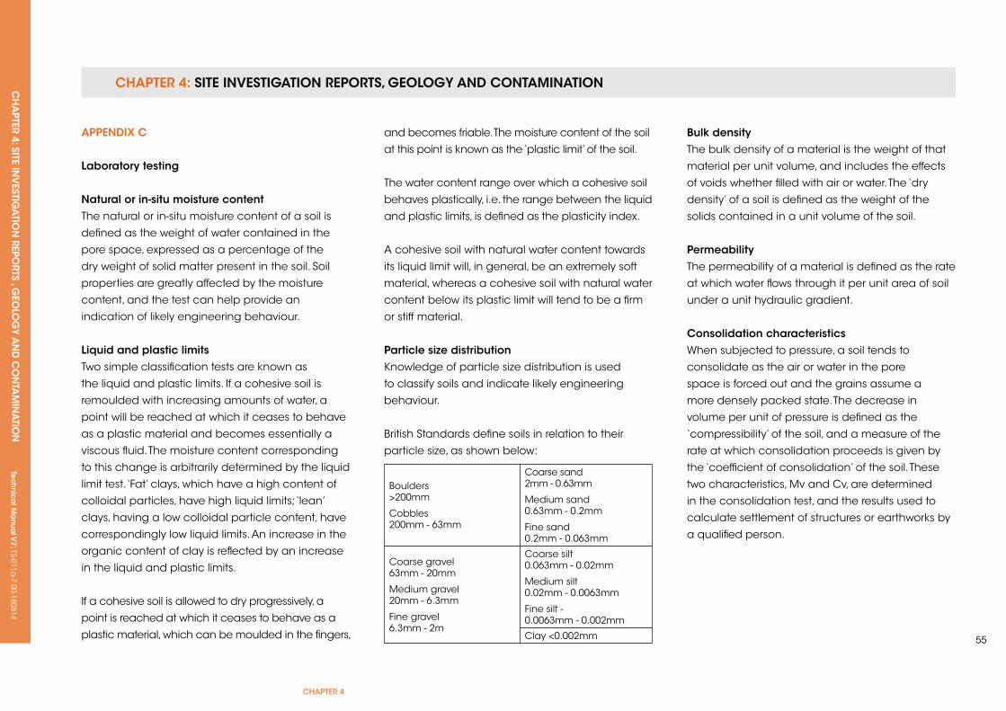
CHAPTER 4: SiTE invESTigATion REPoRTS, gEology And ConTAminATionCH
APTER 4: SiTE in
vESTig
ATio
n REPo
RTS , gEo
log
y An
d C
on
TAm
inA
Tion
Tec
hn
ica
l ma
nua
l v7: TS-011a
-7.00-180814
CHAPTER 4
55
Boulders >200mm
Cobbles 200mm - 63mm
Coarse sand 2mm - 0.63mm
Medium sand 0.63mm - 0.2mm
Fine sand0.2mm - 0.063mm
Coarse gravel 63mm - 20mm
Medium gravel 20mm - 6.3mm
Fine gravel 6.3mm - 2m
Coarse silt 0.063mm - 0.02mm
Medium silt 0.02mm - 0.0063mm
Fine silt - 0.0063mm - 0.002mm
Clay <0.002mm
APPenDix C
Laboratory testing
natural or in-situ moisture contentThe natural or in-situ moisture content of a soil is
defined as the weight of water contained in the
pore space, expressed as a percentage of the
dry weight of solid matter present in the soil. Soil
properties are greatly affected by the moisture
content, and the test can help provide an
indication of likely engineering behaviour.
Liquid and plastic limitsTwo simple classification tests are known as
the liquid and plastic limits. If a cohesive soil is
remoulded with increasing amounts of water, a
point will be reached at which it ceases to behave
as a plastic material and becomes essentially a
viscous fluid. The moisture content corresponding
to this change is arbitrarily determined by the liquid
limit test. ‘Fat’ clays, which have a high content of
colloidal particles, have high liquid limits; ‘lean’
clays, having a low colloidal particle content, have
correspondingly low liquid limits. An increase in the
organic content of clay is reflected by an increase
in the liquid and plastic limits.
If a cohesive soil is allowed to dry progressively, a
point is reached at which it ceases to behave as a
plastic material, which can be moulded in the fingers,
and becomes friable. The moisture content of the soil
at this point is known as the ‘plastic limit’ of the soil.
The water content range over which a cohesive soil
behaves plastically, i.e. the range between the liquid
and plastic limits, is defined as the plasticity index.
A cohesive soil with natural water content towards
its liquid limit will, in general, be an extremely soft
material, whereas a cohesive soil with natural water
content below its plastic limit will tend to be a firm
or stiff material.
Particle size distributionknowledge of particle size distribution is used
to classify soils and indicate likely engineering
behaviour.
British Standards define soils in relation to their
particle size, as shown below:
Bulk densityThe bulk density of a material is the weight of that
material per unit volume, and includes the effects
of voids whether filled with air or water. The ‘dry
density’ of a soil is defined as the weight of the
solids contained in a unit volume of the soil.
PermeabilityThe permeability of a material is defined as the rate
at which water flows through it per unit area of soil
under a unit hydraulic gradient.
Consolidation characteristicsWhen subjected to pressure, a soil tends to
consolidate as the air or water in the pore
space is forced out and the grains assume a
more densely packed state. The decrease in
volume per unit of pressure is defined as the
‘compressibility’ of the soil, and a measure of the
rate at which consolidation proceeds is given by
the ‘coefficient of consolidation’ of the soil. These
two characteristics, Mv and Cv, are determined
in the consolidation test, and the results used to
calculate settlement of structures or earthworks by
a qualified person.
CHAPTER 4: SiTE invESTigATion REPoRTS, gEology And ConTAminATionCH
APTER 4: SiTE in
vESTig
ATio
n REPo
RTS , gEo
log
y An
d C
on
TAm
inA
Tion
Tec
hn
ica
l ma
nua
l v7: TS-011a
-7.00-180814
strength characteristicsThe strength of geological materials is generally
expressed as the maximum resistance that they
offer to deformation or fracture by applied shear
or compressive stress. The strength characteristics
of geological materials depend to an important
degree on their previous history and on the
conditions under which they will be stressed in
practice. Consequently, it is necessary to simulate
in the laboratory tests the conditions under which
the material will be stressed in the field.
In general, the only test carried out on hard rocks
is the determination of their compressive strength,
but consideration must also be given to fissuring,
jointing and bedding planes.
The tests currently used for soils and soft rocks fall
into two main categories. First, those in which the
material is stressed under conditions of no moisture
content change, and second, those in which
full opportunity is permitted for moisture content
changes under the applied stresses.
Tests in the first category are known as undrained
(immediate or quick) tests, while those in the
second category are known as drained (slow or
equilibrium) tests. The tests are normally carried
out in the triaxial compression apparatus, but
granular materials may be tested in the shear box
apparatus.
The undrained triaxial test gives the apparent
(cohesion) Cu and the angle of shearing (resistance)
Øu. In dry sands, Cu = 0 and Øu is equal to the
angle of internal friction, whereas with saturated
non-fissured clays Øu tends to 0 and the apparent
cohesion Cu is equal to one-half the unconfined
compression strength qu. On-site, the vane test gives
an approximate measure of shear strength.
For some stability problems, use is made of a
variant of the undrained triaxial test in which the
specimen is allowed to consolidate fully under the
hydrostatic pressure, and is then tested to failure
under conditions of no moisture content change.
This is known as the consolidated undrained triaxial
test. Pore water pressures may be measured during
this test, or alternatively a fully drained test may
be carried out. In either case, the effective shear
strength parameters C’ and Ø’ can be obtained,
which can be used to calculate shear strength at
any given pore water pressure.
CompactionThe density at which any soil can be placed in
an earth dam, embankment or road depends on
its moisture content and on the amount of work
used in compaction. The influence of these two
factors can be studied in compaction tests, which
can determine the maximum dry density (MDD)
achievable at a certain optimum moisture content
(OMC).
California Bearing ratio (CBr) testIn flexible pavement design, knowledge of the
bearing capacity of the sub-grade is necessary
to determine the thickness of pavement for
any particular combination of traffic and site
conditions. The quality of the subgrade can
be assessed by means of the CBR test, or
approximately by the MExE cone penetrometer.
Chemical testsknowledge of the total soluble sulphate content
and pH of soils and ground water is important in
determining the protection required for concrete
or steel in contact with the ground. Other specialist
tests may be carried out on sites suspected of
being contaminated by toxic materials.
CH
APTER 5: FO
UN
DA
TION
STe
ch
nic
al M
anu
al V
7: TS-011a-7.00-180814
CHAPTER 5
57
CHAPTer 5: founDATions
ConTenTs
5.1 GROuND IMPROVEMENT
5.2 FOuNDATIONS, TREES AND CLAy
5.3 STRIP AND MASS FILLED FOuNDATIONS
5.4 PILED FOuNDATIONS
5.5 RAFT FOuNDATIONS
Tec
hn
ica
l Ma
nua
l V6: TS-011a
-6.00-010413Te
ch
nic
al M
anu
al V
7: TS-011a-7.00-180814
FUNCTIONAL REQUIREMENTS
5.1 grounD iMProveMenT
Workmanshipi. All workmanship must be within the tolerances defined in Chapter 1
of this Manual.
ii. All work is to be carried out by a technically competent person in
a workmanlike manner.
iii. Ground improvement schemes should be appropriately tested
to confirm that the completed works meet design specifications.
The testing regime must be agreed with the Warranty Surveyor prior to
commencement of work.
iv. The Developer shall ensure that adequate quality control procedures
are in place. The quality control must identify that site work meets the
design intention. All procedures should be auditable and available for
inspection.
Materialsi. All materials should be stored correctly in a manner that will not cause
damage or deterioration of the product.
ii. All materials, products and building systems shall be appropriate and
suitable for their intended purpose.
iii. The structure shall, unless specifically agreed otherwise with the
Warranty provider, have a life of not less than 60 years. Individual
components and assemblies, not integral to the structure, may have a
lesser durability, but not in any circumstances less than 15 years.
Designi. The design and specifications shall provide a clear indication of the
design intent and demonstrate a satisfactory level of performance.
ii. Site investigation by an appropriately qualified person should be
supplied and provide the following information:
a. Depth of original soil types below the structure.
b. Details of any filled ground and its suitability to accept ground
improvements techniques.
c. Gas generation or spontaneous combustion from ground
conditions.
The investigation must be endorsed by the Specialist Foundations
Contractor.
iii. Structural elements outside the parameters of Approved Document
A (England and Wales) must be supported by structural calculations
provided by a suitably qualified expert.
iv. The ground improvement works must meet the relevant Building
Regulations, British Standards, Eurocodes and other statutory
requirements.
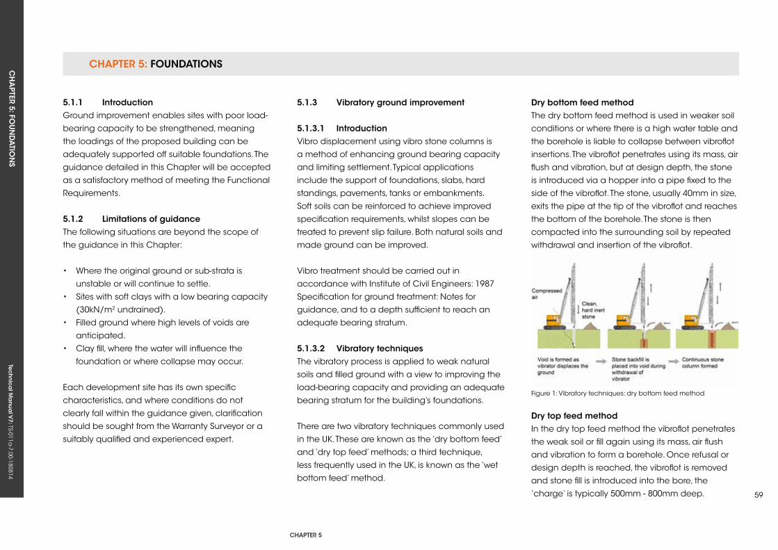
CHAPTER 5: FOUNDATIONSCH
APTER 5: FO
UN
DA
TION
STe
ch
nic
al M
anu
al V
7: TS-011a-7.00-180814
CHAPTER 5
59
Figure 1: Vibratory techniques: dry bottom feed method
5.1.1 introductionGround improvement enables sites with poor load-
bearing capacity to be strengthened, meaning
the loadings of the proposed building can be
adequately supported off suitable foundations. The
guidance detailed in this Chapter will be accepted
as a satisfactory method of meeting the Functional
Requirements.
5.1.2 Limitations of guidanceThe following situations are beyond the scope of
the guidance in this Chapter:
• Where the original ground or sub-strata is
unstable or will continue to settle.
• Sites with soft clays with a low bearing capacity
(30kN/m2 undrained).
• Filled ground where high levels of voids are
anticipated.
• Clay fill, where the water will influence the
foundation or where collapse may occur.
Each development site has its own specific
characteristics, and where conditions do not
clearly fall within the guidance given, clarification
should be sought from the Warranty Surveyor or a
suitably qualified and experienced expert.
5.1.3 vibratory ground improvement
5.1.3.1 introductionVibro displacement using vibro stone columns is
a method of enhancing ground bearing capacity
and limiting settlement. Typical applications
include the support of foundations, slabs, hard
standings, pavements, tanks or embankments.
Soft soils can be reinforced to achieve improved
specification requirements, whilst slopes can be
treated to prevent slip failure. Both natural soils and
made ground can be improved.
Vibro treatment should be carried out in
accordance with Institute of Civil Engineers: 1987
Specification for ground treatment: Notes for
guidance, and to a depth sufficient to reach an
adequate bearing stratum.
5.1.3.2 vibratory techniquesThe vibratory process is applied to weak natural
soils and filled ground with a view to improving the
load-bearing capacity and providing an adequate
bearing stratum for the building’s foundations.
There are two vibratory techniques commonly used
in the uk. These are known as the ‘dry bottom feed’
and ‘dry top feed’ methods; a third technique,
less frequently used in the uk, is known as the ‘wet
bottom feed’ method.
Dry bottom feed methodThe dry bottom feed method is used in weaker soil
conditions or where there is a high water table and
the borehole is liable to collapse between vibroflot
insertions. The vibroflot penetrates using its mass, air
flush and vibration, but at design depth, the stone
is introduced via a hopper into a pipe fixed to the
side of the vibroflot. The stone, usually 40mm in size,
exits the pipe at the tip of the vibroflot and reaches
the bottom of the borehole. The stone is then
compacted into the surrounding soil by repeated
withdrawal and insertion of the vibroflot.
Dry top feed methodIn the dry top feed method the vibroflot penetrates
the weak soil or fill again using its mass, air flush
and vibration to form a borehole. Once refusal or
design depth is reached, the vibroflot is removed
and stone fill is introduced into the bore, the
‘charge’ is typically 500mm - 800mm deep.
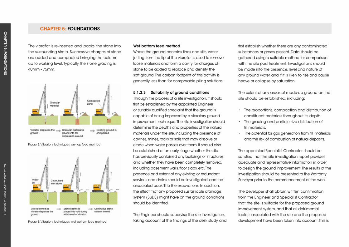
CHAPTER 5: FOUNDATIONSCH
APTER 5: FO
UN
DA
TION
STe
ch
nic
al M
anu
al V
7: TS-011a-7.00-180814
Figure 2: Vibratory techniques: dry top feed method
Figure 3: Vibratory techniques: wet bottom feed method
The vibroflot is re-inserted and ‘packs’ the stone into
the surrounding strata. Successive charges of stone
are added and compacted bringing the column
up to working level. Typically the stone grading is
40mm - 75mm.
Wet bottom feed methodWhere the ground contains fines and silts, water
jetting from the tip of the vibroflot is used to remove
loose materials and form a cavity for charges of
stone to be added to replace and densify the
soft ground. The carbon footprint of this activity is
generally less than for comparable piling solutions.
5.1.3.3 suitability of ground conditionsThrough the process of a site investigation, it should
first be established by the appointed Engineer
or suitably qualified specialist that the ground is
capable of being improved by a vibratory ground
improvement technique. The site investigation should
determine the depths and properties of the natural
materials under the site, including the presence of
cavities, mines, rocks or soils that may dissolve or
erode when water passes over them. It should also
be established at an early stage whether the site
has previously contained any buildings or structures,
and whether they have been completely removed,
including basement walls, floor slabs, etc. The
presence and extent of any existing or redundant
services and drains should be investigated, and the
associated backfill to the excavations. In addition,
the effect that any proposed sustainable drainage
system (SuDS) might have on the ground conditions
should be identified.
The Engineer should supervise the site investigation,
taking account of the findings of the desk study, and
first establish whether there are any contaminated
substances or gases present. Data should be
gathered using a suitable method for comparison
with the site post treatment. Investigations should
be made into the presence, level and nature of
any ground water, and if it is likely to rise and cause
heave or collapse by saturation.
The extent of any areas of made-up ground on the
site should be established, including:
• The proportions, compaction and distribution of
constituent materials throughout its depth.
• The grading and particle size distribution of
fill materials.
• The potential for gas generation from fill materials,
and the risk of combustion of natural deposits.
The appointed Specialist Contractor should be
satisfied that the site investigation report provides
adequate and representative information in order
to design the ground improvement. The results of the
investigation should be presented to the Warranty
Surveyor prior to the commencement of the work.
The Developer shall obtain written confirmation
from the Engineer and Specialist Contractor
that the site is suitable for the proposed ground
improvement system, and that all detrimental
factors associated with the site and the proposed
development have been taken into account. This is

CHAPTER 5: FOUNDATIONSCH
APTER 5: FO
UN
DA
TION
STe
ch
nic
al M
anu
al V
7: TS-011a-7.00-180814
CHAPTER 5
61
to be made available to the Warranty Surveyor prior
to the commencement of any work on the site.
site workmanshipThe Specialist Contractor should appoint an
Engineer to supervise the vibratory foundation
works at all times and ensure that:
• The required depth and bearing capacity of
stone columns are achieved.
• The stone columns are correctly located
beneath the proposed foundation and in
accordance with design drawings.
Figure 4: The intersection of adjacent reinforced concrete strips
Figure 5: Typical engineered fill construction
5.1.4 engineered fill
5.1.4.1 Design of engineered fillCareful selection of the material and controlled
placement should ensure that the engineered fill
forms an adequate foundation material; however,
in some circumstances, significant ground
movements can occur. Engineered fill should
be designed and placed in accordance with
recognised good practice, as noted in references
at the end of this section.
Engineered fills used to produce suitably shaped
landforms for structures should be constructed
to high standards to minimise the risk of ground
movements causing damage to property built on
shallow foundations.
In designing and specifying a fill to form a
foundation for buildings, the following technical
requirements should be established:
• A well-constructed excavation, safely executed,
with all soft and hard spots removed, and made
reasonably dry and well drained.
• Sound fill without undesirable material and
capable of compaction as specified, provided
with starter and capping layers as necessary.
• Placement and compaction to ensure that the
performance of the fill will meet required criteria
as a foundation fill.
• Appropriate monitoring; the Designer must
ensure that all work can be carried out
safely as required by the Health and Safety
Executive Construction Design and
Management Regulations.
CHAPTER 5: FOUNDATIONSCH
APTER 5: FO
UN
DA
TION
STe
ch
nic
al M
anu
al V
7: TS-011a-7.00-180814
5.1.4.2 fill selectionFill should be clearly categorised into material that
may and may not be used: unsuitable fill, general
fill, restricted fill and special fill. Fill materials must
not present an environmental or health hazard.
unsuitable fill should not be used at any location
on the site.
General fill is all material except that which is
unsuitable, restricted or special, and is normally
the majority of the material used. It may include
natural soils as well as some waste products.
Restricted fill is material that would be general fill
except that it contains minerals hostile to the built
environment. It can include natural materials such
as pyritic shales, sulfate-bearing clays and waste
materials, including burnt colliery discard and steel
slag. Its use is precluded where ground water could
rise to the underside of the deepest foundation, or
where it is rejected for pollution reasons. For some
developments, such as housing with gardens,
restricted fills would include fills that are harmful to
people.
Special fill is high-quality material, such as well-
graded natural sands and gravels, crushed rock
or clean demolition rubble. Its use will often have
to be reserved for specifically defined purposes,
such as a capping layer or backfill to retaining
walls. Where possible though, granular soils should
be used as general fill since these materials drain
readily and consolidate quickly. The smaller the
predominant particle size, the longer the potential
time required for consolidation under the self-
weight of the fill.
5.1.4.3 end product criteriaThe greatest threats to successful in-service
performance are:
• Collapse settlement due to inundation of dry
or inadequately compacted fills.
• Excessive consolidation settlement of wet
compressible fill.
• Heave or settlement of clay fills due to climatic
changes or vegetation.
These ground movements depend on moisture
movement, so by reducing the voids in a fill, the
opportunities for excessive in-service movements
should be restricted. A maximum allowable air-
voids content of 5% is a suitable criterion for most
clay fills. However, specifying a 5% air-voids content
is insufficient, as this value may easily be achieved
by adding water to the fill without increasing
compactive effort. A suitable alternative control
method is to specify a minimum acceptable
density as a proportion of the maximum dry density
measured in a standard laboratory compaction
test. Limits on moisture content are required also.
If the fill is too wet, there could be excessive
consolidation settlement, and if the fill is too dry, it
might be vulnerable to collapse compression.
5.1.4.4 Placing engineered fillA successful engineered fill requires not only an
appropriate specification but also adequate control
during placement. All the work must be carried
out with due regard to safety, as required by the
Construction Design and Management Regulations.
5.1.4.5 site preparation and disposition of fillThe site should be cleared of all topsoil and other
unsuitable material.
Soft spots and hard spots, such as derelict
foundations, should be removed, together with ponds
and surface water from depressions. Removing water
by pumping may be necessary when filling some
excavations below the ground water level.
When a variety of material types are used as fill,
they should be deposited in horizontal layers
across the site. If there is only a limited amount
of good granular material, it will be best to use it
in layers interspersed between layers of poorer
cohesive fill.
The fill thicknesses should be reasonably constant
beneath a structure to minimise differential
settlement.
CHAPTER 5: FOUNDATIONSCH
APTER 5: FO
UN
DA
TION
STe
ch
nic
al M
anu
al V
7: TS-011a-7.00-180814
CHAPTER 5
63
Feather-edges, resulting in foundations set partly
on fill and partly on natural ground, should be
avoided, and the site worked in such a way that
structures are located either directly on natural
ground or directly over fill of a consistent thickness.
If fill is to be placed over sloping natural ground,
some stepping of the ground may be necessary.
Construction over the face of a quarry or an
opencast mining high wall should be avoided.
Special measures may have to be taken by
providing flexible connections for services at
the location of high walls and by thickening
construction for service and estate roads.
If the natural ground on which the fill rests is soft
and compressible (for example, layers of peat
or soft clay), the surface of the fill may settle
appreciably and unevenly as a result of the weight
of the fill consolidating the soft layers below. This
settlement will, of course, be additional to that
resulting from the compression of the fill itself.
Sensitive structures may warrant a surface (or
capping) layer formed from special fill compacted
to more onerous standards than the underlying fill.
This should help minimise the differential settlement
suffered by the structure.
Where landscaped or other non load-bearing
areas form part of a development, they need less
compaction than the load-bearing areas. There
should be a transition zone around the load-
bearing area, as shown in Figure 5.
5.1.4.6 fill placementFill should be placed in horizontal layers, with each
layer separately compacted. For a given item of
plant, compaction performance will be determined
by fill layer thickness, fill moisture content and the
number of passes of the compaction equipment.
There are, however, other factors such as the need
to avoid excessive handling.
Whenever possible, site trials should be undertaken
to determine the correct criteria. Some general
information about placing fills is given in BS 6031.
Each layer should be of a thickness that allows the
compactive energy to spread throughout the layer,
producing the specified fill density and low air-voids
content. Loose layers with a thickness greater than
250mm are unlikely to be satisfactory for earth fills
compacted to support low rise structures.
It may be necessary to use layers of 200mm or
less. Moisture content at the time of placing a
fill is fundamental to subsequent performance,
particularly where the fill contains a large
proportion of fine grained cohesive material. If
the fill is too dry, there is the possibility of heave
or collapse settlement; if it is too wet, there is
the possibility of insufficient strength and high
compressibility. It will be difficult to achieve an
air-voids content of 5% or less when the moisture
content is low. In the same way that the addition of
too much water can detract from the performance
of engineered fill, soil can be over-compacted.
Granular soils and cohesive soils drier than
optimum, when rolled excessively, become over-
stressed, and what should have been a firm
compacted surface becomes a loose tilth. This
should be avoided whenever possible. Where a
fill containing a large proportion of fine grained
cohesive material (for example, clay) is used, filling
during wet weather should be avoided.
5.1.4.7 Quality controlquality control procedures should be implemented
to ensure compliance with the specification. The
nature of the control procedure will depend on the
type of specification adopted. The end product
specification requires an appropriate type and
quantity of testing of the fill during placement
to ensure that the desired end product is being
achieved. Depending upon the type of contract,
quality control may be the responsibility of the
Engineer or of the Contractor working under the
supervision of the Engineer. Control parameters
should be the same as those determined during
the site investigation stage. Both design and control
parameters must be reproducible, a term that
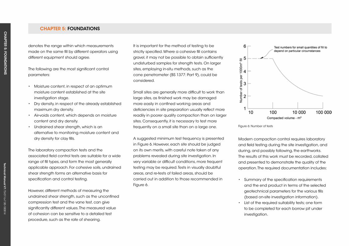
CHAPTER 5: FOUNDATIONSCH
APTER 5: FO
UN
DA
TION
STe
ch
nic
al M
anu
al V
7: TS-011a-7.00-180814
denotes the range within which measurements
made on the same fill by different operators using
different equipment should agree.
The following are the most significant control
parameters:
• Moisture content, in respect of an optimum
moisture content established at the site
investigation stage.
• Dry density, in respect of the already established
maximum dry density.
• Air-voids content, which depends on moisture
content and dry density.
• undrained shear strength, which is an
alternative to monitoring moisture content and
dry density for clay fills.
The laboratory compaction tests and the
associated field control tests are suitable for a wide
range of fill types, and form the most generally
applicable approach. For cohesive soils, undrained
shear strength forms an alternative basis for
specification and control testing.
However, different methods of measuring the
undrained shear strength, such as the unconfined
compression test and the vane test, can give
significantly different values. The measured value
of cohesion can be sensitive to a detailed test
procedure, such as the rate of shearing.
Figure 6: Number of tests
It is important for the method of testing to be
strictly specified. Where a cohesive fill contains
gravel, it may not be possible to obtain sufficiently
undisturbed samples for strength tests. On larger
sites, employing in-situ methods, such as the
cone penetrometer (BS 1377: Part 9), could be
considered.
Small sites are generally more difficult to work than
large sites, as finished work may be damaged
more easily in confined working areas and
deficiencies in site preparation usually reflect more
readily in poorer quality compaction than on larger
sites. Consequently, it is necessary to test more
frequently on a small site than on a large one.
A suggested minimum test frequency is presented
in Figure 6. However, each site should be judged
on its own merits, with careful note taken of any
problems revealed during site investigation. In
very variable or difficult conditions, more frequent
testing may be required. Tests in visually doubtful
areas, and re-tests of failed areas, should be
carried out in addition to those recommended in
Figure 6.
Modern compaction control requires laboratory
and field testing during the site investigation, and
during, and possibly following, the earthworks.
The results of this work must be recorded, collated
and presented to demonstrate the quality of the
operation. The required documentation includes:
• Summary of the specification requirements
and the end product in terms of the selected
geotechnical parameters for the various fills
(based on-site investigation information).
• List of the required suitability tests; one form
to be completed for each borrow pit under
investigation.
CHAPTER 5: FOUNDATIONSCH
APTER 5: FO
UN
DA
TION
STe
ch
nic
al M
anu
al V
7: TS-011a-7.00-180814
CHAPTER 5
65
• Suitability test results for each borrow pit.
• List of the required control tests.
• Results of the control tests on each fill type, layer
or area, as appropriate.
• A list of post-compaction monitoring
requirements.
• The results of post-compaction monitoring; all
completed forms should be signed and dated
by the person responsible, and a list prepared
of any required action or remedial work to be
carried out.
5.1.4.8 Monitoring of fill performanceMonitoring provides a check on the performance
of the fill after compaction, and is particularly
important where vulnerable structures are to be built
or foundation loading is unusually large. It is also
required where the fill is relatively deep or substantial
ground water rise within the fill is expected.
Monitoring techniques include:
• Surface levelling stations to measure the
settlement of the fill surface.
• Magnet extensometers to measure the
settlement of incremental depths of fill.
• Standpipe piezometers to measure the rise in the
ground water table in the fill after placement.
• Load tests for direct estimation of settlement of
surface layers produced by loadings.
Surface levelling stations are easy to install and
very effective. By optical levelling of the stations,
measurement can be made of the total vertical
movement of the fill upon which they rest, together
with any movement of the underlying natural
ground, although this is unlikely to be large if all soft
material has been removed prior to compaction.
Levelling stations should be sufficiently robust to
resist damage due to construction traffic. A round
headed bolt cast into a 1m concrete cube set
300mm into the fill has been found to be effective.
Magnet extensometers are unlikely to be necessary
in shallow-depth fill. Standpipes or piezometers will
be of advantage if there is reason to suspect that
ground water will rise into the fill at any time in the
future, with consequent settlement.
5.1.5 TestingTesting is carried out to confirm that the ground
improvement works meet the design criteria. The
tests are usually completed to determine the
ground bearing capacity.
The Engineer shall require the Specialist Contractor to
verify that the ground treatment has been completed
to a satisfactory standard. This will usually include
carrying out suitable testing to establish the degree of
ground improvement, its load-bearing characteristics
and settlement potential. These tests may include:
5.1.5.1 Plate testsThis test will not determine the design but will allow
for an assessment of the workmanship on the stone
columns. Plate tests should be carried out on stone
columns or treated ground at a frequency of at
least one test per day per rig.
The plate tests should be carried out with a 600mm
diameter plate and minimum test load of 11 tonnes.
5.1.5.2 Mini zone testsA mini zone test (dummy footing) can be used as
a limited substitute for zone tests. The test should
be applied to at least two stone columns and the
area of foundation they support. To be useful, mini
zone tests should be continued for long enough to
establish the presence of creep behaviour.
Mini zone tests (dummy footing) should be carried
out at a rate of one test per 1000m2–3000m2 of
treated ground, along with penetration tests at a
rate of one test for 20–50 stone columns, or one test
for not more than 500m2 of treated ground, with a
minimum of one test per structural unit.
Alternatively, in the absence of penetration tests, one
test per ten houses (with a minimum of two tests per
site) would suffice.
CHAPTER 5: FOUNDATIONSCH
APTER 5: FO
UN
DA
TION
STe
ch
nic
al M
anu
al V
7: TS-011a-7.00-180814
5.1.5.3 Zone testsAn isolated pad or strip footing is used to test up to
eight stone columns and the intervening ground.
Loadings, which should simulate the dwelling loads,
are held for 24 hours at predetermined stages to
examine creep behaviour.
5.1.5.4 in-situ testsWhere vibration will improve the ground itself, e.g.
granular materials, then in-situ testing is appropriate.
The improvement can be assessed when the test
results are compared with the in-situ test results
recorded during the pre-treatment investigation.
5.1.5.5 Trial pitsTrial pits can be excavated around trial stone
columns to prove that they are fully formed and
to the required depth and diameter. This is a
destructive test, and allowance should be made
accordingly.
On completion of the treatment, the Engineer
should satisfy himself that the treated ground has
achieved the anticipated condition assumed in
the design, and provide evidence in writing to the
Warranty Surveyor.
5.1.6 fill materialsThe following materials require testing to ensure
their suitability for use as fill to support structural
foundations and slabs, or as backfill to associated
trenches:
• Acid wastes
• Reactive materials
• Materials that include sulphates (e.g. gypsum)
• Organic materials
• Toxic materials
• Materials that cause noxious fumes, rot, undue
settlement or damage to surrounding materials
The sample tests should be carried out by a suitably
qualified person, and it may be necessary to
take a number of samples to identify the material
characteristics of the fill accurately.
5.1.7 sources of fill materialWhere the material is of a stable and uniform type
from one source, the testing regime may be reduced.
However, if the material is variable or from a number
of sources, regular inspections and/or testing may
be required. Recycled aggregate or other building
materials, such as crushed brick, should only be used
following an inspection by the Warranty Surveyor
Colliery shale and any other residue from mineral
extraction or industrial process bi-products should
only be used with specialist approval.
5.1.8 suitable foundations for sites with improved groundFoundations on sites with improved ground should
either be of a reinforced strip or raft type. Both
foundations will require a full design by a Structural
Engineer.
For ‘low rise structures’, the foundations should
be designed to ensure a maximum settlement of
25mm is not exceeded. In relation to differential
settlement, a design limit for maximum tilt of 1/500 is
appropriate. More stringent values may be required
due to the particular circumstances (e.g. medium
and high rise structures).
Functional Requirement 5.2 must be met where
the foundations are bearing on cohesive soils or
cohesive fill materials and trees nearby.
5.1.9 relevant British standards and guidance documentsRelevant British Standards, Codes of Practice and
authoritative documents include:
• BS 6031 Code of Practice for earthworks
• BS 1377: Part 9 Methods of tests for soils for civil
engineering purposes. In-situ tests
• BS 10175 Investigation of potentially
contaminated sites – Code of Practice
• BS EN 1991 Actions on structures

CHAPTER 5: FOUNDATIONSCH
APTER 5: FO
UN
DA
TION
STe
ch
nic
al M
anu
al V
7: TS-011a-7.00-180814
CHAPTER 5
67
• BS EN 14731 Execution of special geotechnical
works. Ground treatment by deep vibration
• BS EN 1997-1 General rules
• BS EN 1997-2 Ground investigation and testing
• BS EN ISO 14688 Geotechnical investigation and
testing – Identification and classification of soil
• BS EN ISO 14689 Geotechnical investigation and
testing – Identification and classification of rock
• BS EN ISO 22476 Geotechnical investigation and
testing – Field testing
• BR 391 Specifying vibro stone columns
• Institute of Civil Engineers (ICE) Specification for
ground treatment: Notes for guidance, 1987
• CIRIA C572: Treated ground: Engineering
properties and performance, 2002
• CIRIA C573: A guide to ground treatment, 2002
• BRE 424: Building on fill: Geotechnical aspects
• BRE Information Paper 5/97: Collapse
compression on inundation
Tec
hn
ica
l Ma
nua
l V6: TS-011a
-6.00-010413Te
ch
nic
al M
anu
al V
7: TS-011a-7.00-180814
FUNCTIONAL REQUIREMENTS
5.2 founDATions, Trees AnD CLAy
Workmanshipi. All workmanship must be within the tolerances defined in Chapter 1
of this Manual.
ii. All work is to be carried out by a technically competent person in
a workmanlike manner.
iii. Strip foundations should be of a suitable depth in order to achieve
a satisfactory level of performance.
Materialsi. All materials should be stored correctly in a manner that will not cause
damage or deterioration of the product.
ii. All materials, products and building systems shall be appropriate and
suitable for their intended purpose.
iii. The structure shall, unless specifically agreed otherwise with
the Warranty provider, have a life of not less than 60 years. Individual
components and assemblies, not integral to the structure, may have a
lesser durability, but not in any circumstances less than 15 years.
Designi. The design and specifications shall provide a clear indication of the
design intent and demonstrate a satisfactory level of performance;
ii. Foundation type and depth must be suitable to resist movement due
to the influence of nearby trees.
iii. Structural elements outside the parameters of Approved Document
A (England and Wales) must be supported by structural calculations
provided by a suitably qualified expert.
iv. The design and construction of the foundations must meet the
relevant Building Regulations, British Standards, Eurocodes and other
statutory requirements.
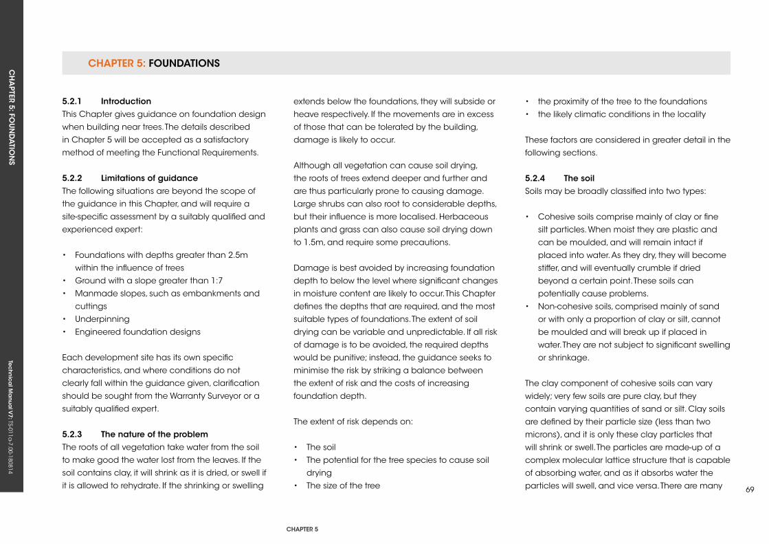
CHAPTER 5: FOUNDATIONSCH
APTER 5: FO
UN
DA
TION
STe
ch
nic
al M
anu
al V
7: TS-011a-7.00-180814
CHAPTER 5
69
5.2.1 introductionThis Chapter gives guidance on foundation design
when building near trees. The details described
in Chapter 5 will be accepted as a satisfactory
method of meeting the Functional Requirements.
5.2.2 Limitations of guidanceThe following situations are beyond the scope of
the guidance in this Chapter, and will require a
site-specific assessment by a suitably qualified and
experienced expert:
• Foundations with depths greater than 2.5m
within the influence of trees
• Ground with a slope greater than 1:7
• Manmade slopes, such as embankments and
cuttings
• underpinning
• Engineered foundation designs
Each development site has its own specific
characteristics, and where conditions do not
clearly fall within the guidance given, clarification
should be sought from the Warranty Surveyor or a
suitably qualified expert.
5.2.3 The nature of the problemThe roots of all vegetation take water from the soil
to make good the water lost from the leaves. If the
soil contains clay, it will shrink as it is dried, or swell if
it is allowed to rehydrate. If the shrinking or swelling
extends below the foundations, they will subside or
heave respectively. If the movements are in excess
of those that can be tolerated by the building,
damage is likely to occur.
Although all vegetation can cause soil drying,
the roots of trees extend deeper and further and
are thus particularly prone to causing damage.
Large shrubs can also root to considerable depths,
but their influence is more localised. Herbaceous
plants and grass can also cause soil drying down
to 1.5m, and require some precautions.
Damage is best avoided by increasing foundation
depth to below the level where significant changes
in moisture content are likely to occur. This Chapter
defines the depths that are required, and the most
suitable types of foundations. The extent of soil
drying can be variable and unpredictable. If all risk
of damage is to be avoided, the required depths
would be punitive; instead, the guidance seeks to
minimise the risk by striking a balance between
the extent of risk and the costs of increasing
foundation depth.
The extent of risk depends on:
• The soil
• The potential for the tree species to cause soil
drying
• The size of the tree
• the proximity of the tree to the foundations
• the likely climatic conditions in the locality
These factors are considered in greater detail in the
following sections.
5.2.4 The soilSoils may be broadly classified into two types:
• Cohesive soils comprise mainly of clay or fine
silt particles. When moist they are plastic and
can be moulded, and will remain intact if
placed into water. As they dry, they will become
stiffer, and will eventually crumble if dried
beyond a certain point. These soils can
potentially cause problems.
• Non-cohesive soils, comprised mainly of sand
or with only a proportion of clay or silt, cannot
be moulded and will break up if placed in
water. They are not subject to significant swelling
or shrinkage.
The clay component of cohesive soils can vary
widely; very few soils are pure clay, but they
contain varying quantities of sand or silt. Clay soils
are defined by their particle size (less than two
microns), and it is only these clay particles that
will shrink or swell. The particles are made-up of a
complex molecular lattice structure that is capable
of absorbing water, and as it absorbs water the
particles will swell, and vice versa. There are many
CHAPTER 5: FOUNDATIONSCH
APTER 5: FO
UN
DA
TION
STe
ch
nic
al M
anu
al V
7: TS-011a-7.00-180814
different types of clay with different molecular
structures, and all of which have different swelling
characteristics. The extent of swelling and shrinkage
that can occur will therefore depend on the type
of clay particles and the proportion of clay, as
opposed to silt or sand, within the soil.
The potential of soil to swell or shrink can be
determined by simple tests to determine its plastic
limit (the moisture content below which it changes
from being plastic and mouldable, and starts to
crumble) and liquid limit (the moisture content
above which it changes from being plastic, and
starts to flow like a liquid). The plastic and liquid
limits can be determined by simple laboratory
tests in accordance with BS 1377. The difference
between the plastic and liquid limits is the plasticity
index; the higher the plasticity index, the greater
the potential volume changes.
5.2.5 Potential of the tree species to cause soil dryingTree species differ in the ability of their roots to
grow and exploit the available water in a cohesive
soil, particularly if it has high clay content. This is
commonly referred to as their ‘water demand’.
Species such as Oak, Poplar and Eucalyptus
are deemed as high water demand as they are
particularly efficient at exploiting clay soils, rooting
to considerable depth. A few species only rarely
cause damage and are deemed of low water
demand, whilst the majority fall into the moderate
category.
Hardwood species tend to have a broad spreading
root system, extending considerable distances
laterally as well as to depth. By contrast, the
influence of most conifers is more localised, but just
as deep. A few species (of both hardwoods and
conifers) have intermediate characteristics. The
guidance takes account of the different patterns
of rooting, but it must be emphasised that the
distribution of roots can be variable, meaning the
guidance should not be taken as indicating a
‘zone of influence’ of a tree.
5.2.6 size of treeThe amount of water taken by the roots relates to
the leaf area and the vigour of the tree. With open
grown trees, height is usually considered the best
indicator of leaf area. The greatest water uptake
occurs as the tree reaches maturity, and so ‘mature
height’ is the determining factor. Individual trees
within a group or row will have a smaller leaf area,
but as they compete with each other, the mature
height of the individual trees remains the relevant
factor.
Although some trees are managed as pollards or
are subject to periodic reduction to control their
size, unless such treatment can be assured in the
future, mature height should be used.
5.2.7 ProximityThe closer the tree, the deeper the potential
influence, and the guidance indicates the required
foundation depth at any distance. The parts of the
foundations closest to the tree require the greatest
depth, but if preferred can be stepped down for
more distant parts.
5.2.8 Likely climatic conditionsWeather conditions play a major role in
determining the extent of soil drying. Hot sunny
weather will increase the rate of water uptake
by the roots, whereas rainfall during the summer
can restore the water that has been taken. As the
hottest and driest conditions tend to be in South
East England, it has the greatest risk. For other,
wetter, parts of the country, the guidance allows for
reducing the required foundation depth.
5.2.9 information required for determining the foundation depth
5.2.9.1 establishing ground conditionsThe British Geological Survey website
(www.bgs.ac.uk) can indicate the likely soil
conditions in any locality. Enter the postcode to
locate the site, and a left click on the location
brings up a box that shows the bedrock geology
and the superficial deposits (if present). The name
of the bedrock or superficial deposits are often
sufficient to indicate probable soil conditions
CHAPTER 5: FOUNDATIONSCH
APTER 5: FO
UN
DA
TION
STe
ch
nic
al M
anu
al V
7: TS-011a-7.00-180814
CHAPTER 5
71
(e.g. London Clay or Plateau Gravel), but if not,
clicking on the name will bring up further details.
unless there is clear evidence that a cohesive soil
is not present, site investigations will be required
to determine the soil type to at least the depth of
potential influence of adjacent trees. usually, trial
holes are an acceptable method for determining
the soil strata, but specialist site investigation
reports are preferred if available.
Soil samples should be taken from at least two
depths, at 1.5m and 2.5m (or the base of the trial
hole, whichever is the shallower), and sent to a
soil laboratory for determination of plastic and
liquid limit (and thus plasticity index). In addition,
the moisture content of the samples is usually
determined. The highest value of plasticity index
should be used for determining foundation depth.
5.2.9.2 identification of treesMany local authorities will require a Tree Survey
and Arboricultural Method Statement as part of
the planning application. This will usually serve
to identify all relevant trees both on and off-site.
If a tree survey is not available, assistance with
identification of all of the more common trees can
be obtained from various websites:
natural History Museumwww.nhm.ac.uk/nature-online/britishnatural-
history/urban-tree-survey/identify-trees/tree-key/
index.html
royal Botanic gardens, kewapps.kew.org/trees
science and Plants for school (particularly useful
for winter identification, using twig characteristics)
www-saps.plantsci.cam.ac.uk/trees/index.htm
If a tree cannot be identified, it must be assumed
to have high water demand (deep rooting).
5.2.9.3 Mature height of treeThe mature heights of common tree species are
provided in Table 4 of Appendix A.
Mature height should be used unless:
• An arboricultural report is obtained, indicating
that a lesser height is appropriate for the
conditions of the site.
• Assurance can be provided that the tree will be
maintained at a lesser height at all times in
future.
5.2.9.4 Proximity of treeMeasurement should be taken from the centre of
the trunk to the nearest part of the foundations.
If preferred, foundations depths can be stepped
down at greater distances, in accordance with
Chapter 5.5.4, by measurement to other locations
around the building.
5.2.9.5 Climatic conditionsDetermine from the map in Figure 7 whether the
depth of foundations can be reduced for the
relevant site location.
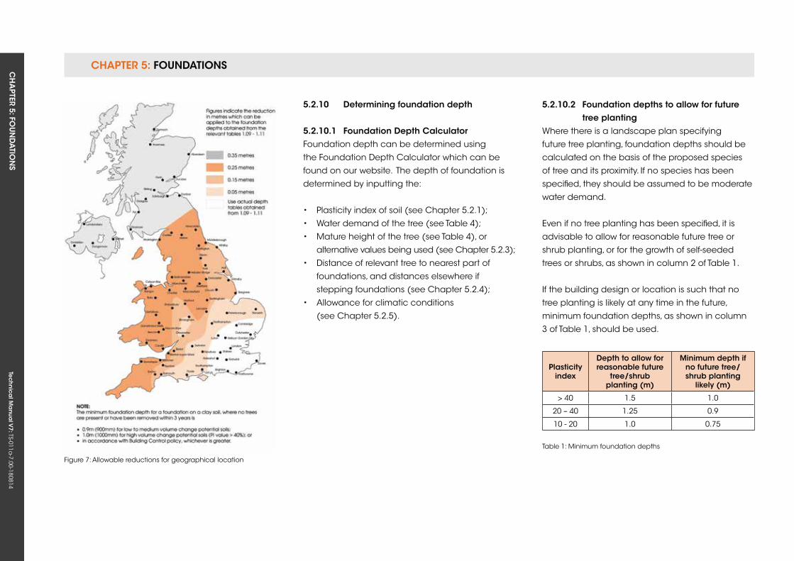
CHAPTER 5: FOUNDATIONSCH
APTER 5: FO
UN
DA
TION
STe
ch
nic
al M
anu
al V
7: TS-011a-7.00-180814
Figure 7: Allowable reductions for geographical location
Plasticity index
Depth to allow forreasonable future
tree/shrub planting (m)
Minimum depth ifno future tree/shrub planting
likely (m)
> 40 1.5 1.0
20 – 40 1.25 0.9
10 - 20 1.0 0.75
Table 1: Minimum foundation depths
5.2.10 Determining foundation depth
5.2.10.1 foundation Depth CalculatorFoundation depth can be determined using
the Foundation Depth Calculator which can be
found on our website. The depth of foundation is
determined by inputting the:
• Plasticity index of soil (see Chapter 5.2.1);
• Water demand of the tree (see Table 4);
• Mature height of the tree (see Table 4), or
alternative values being used (see Chapter 5.2.3);
• Distance of relevant tree to nearest part of
foundations, and distances elsewhere if
stepping foundations (see Chapter 5.2.4);
• Allowance for climatic conditions
(see Chapter 5.2.5).
5.2.10.2 foundation depths to allow for future tree plantingWhere there is a landscape plan specifying
future tree planting, foundation depths should be
calculated on the basis of the proposed species
of tree and its proximity. If no species has been
specified, they should be assumed to be moderate
water demand.
Even if no tree planting has been specified, it is
advisable to allow for reasonable future tree or
shrub planting, or for the growth of self-seeded
trees or shrubs, as shown in column 2 of Table 1.
If the building design or location is such that no
tree planting is likely at any time in the future,
minimum foundation depths, as shown in column
3 of Table 1, should be used.
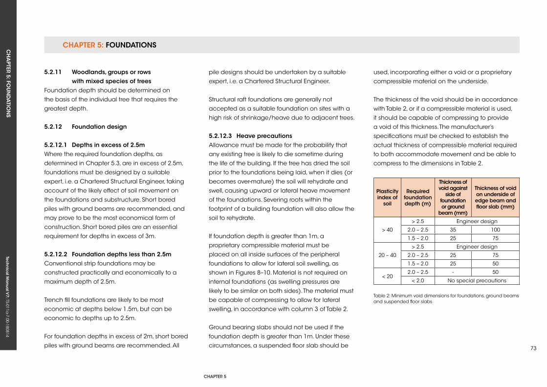
CHAPTER 5: FOUNDATIONSCH
APTER 5: FO
UN
DA
TION
STe
ch
nic
al M
anu
al V
7: TS-011a-7.00-180814
CHAPTER 5
73
Plasticity index of
soil
required foundation depth (m)
Thickness of void against
side of foundation or ground
beam (mm)
Thickness of void on underside of edge beam and floor slab (mm)
> 40
> 2.5 Engineer design
2.0 – 2.5 35 100
1.5 – 2.0 25 75
20 – 40
> 2.5 Engineer design
2.0 – 2.5 25 75
1.5 – 2.0 25 50
< 202.0 – 2.5 - 50
< 2.0 No special precautions
Table 2: Minimum void dimensions for foundations, ground beams and suspended floor slabs
5.2.11 Woodlands, groups or rows with mixed species of treesFoundation depth should be determined on
the basis of the individual tree that requires the
greatest depth.
5.2.12 foundation design
5.2.12.1 Depths in excess of 2.5mWhere the required foundation depths, as
determined in Chapter 5.3, are in excess of 2.5m,
foundations must be designed by a suitable
expert, i.e. a Chartered Structural Engineer, taking
account of the likely effect of soil movement on
the foundations and substructure. Short bored
piles with ground beams are recommended, and
may prove to be the most economical form of
construction. Short bored piles are an essential
requirement for depths in excess of 3m.
5.2.12.2 foundation depths less than 2.5mConventional strip foundations may be
constructed practically and economically to a
maximum depth of 2.5m.
Trench fill foundations are likely to be most
economic at depths below 1.5m, but can be
economic to depths up to 2.5m.
For foundation depths in excess of 2m, short bored
piles with ground beams are recommended. All
pile designs should be undertaken by a suitable
expert, i.e. a Chartered Structural Engineer.
Structural raft foundations are generally not
accepted as a suitable foundation on sites with a
high risk of shrinkage/heave due to adjacent trees.
5.2.12.3 Heave precautionsAllowance must be made for the probability that
any existing tree is likely to die sometime during
the life of the building. If the tree has dried the soil
prior to the foundations being laid, when it dies (or
becomes over-mature) the soil will rehydrate and
swell, causing upward or lateral heave movement
of the foundations. Severing roots within the
footprint of a building foundation will also allow the
soil to rehydrate.
If foundation depth is greater than 1m, a
proprietary compressible material must be
placed on all inside surfaces of the peripheral
foundations to allow for lateral soil swelling, as
shown in Figures 8–10. Material is not required on
internal foundations (as swelling pressures are
likely to be similar on both sides). The material must
be capable of compressing to allow for lateral
swelling, in accordance with column 3 of Table 2.
Ground bearing slabs should not be used if the
foundation depth is greater than 1m. under these
circumstances, a suspended floor slab should be
used, incorporating either a void or a proprietary
compressible material on the underside.
The thickness of the void should be in accordance
with Table 2, or if a compressible material is used,
it should be capable of compressing to provide
a void of this thickness. The manufacturer’s
specifications must be checked to establish the
actual thickness of compressible material required
to both accommodate movement and be able to
compress to the dimensions in Table 2.
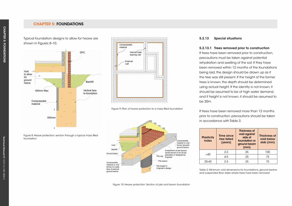
CHAPTER 5: FOUNDATIONSCH
APTER 5: FO
UN
DA
TION
STe
ch
nic
al M
anu
al V
7: TS-011a-7.00-180814
Figure 9: Plan of heave protection to a mass filled foundation
Figure 10: Heave protection: Section of pile and beam foundation
Plasticity index
Time sincetree felled
(years)
Thickness of void against
side of foundation or ground beam
(mm)
Thickness ofvoid belowslab (mm)
>402-3 35 100
4-5 25 75
20-40 2-3 25 75
Table 3: Minimum void dimensions for foundations, ground beams and suspended floor slabs where trees have been removed
Figure 8: Heave protection: section through a typical mass filled foundation
Typical foundation designs to allow for heave are
shown in Figures 8–10.
5.2.13 special situations
5.2.13.1 Trees removed prior to constructionIf trees have been removed prior to construction,
precautions must be taken against potential
rehydration and swelling of the soil. If they have
been removed within 12 months of the foundations
being laid, the design should be drawn up as if
the tree was still present. If the height of the former
trees is known, the depth should be determined
using actual height. If the identity is not known, it
should be assumed to be of high water demand,
and if height is not known, it should be assumed to
be 20m.
If trees have been removed more than 12 months
prior to construction, precautions should be taken
in accordance with Table 3.
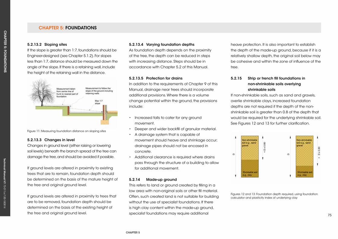
CHAPTER 5: FOUNDATIONSCH
APTER 5: FO
UN
DA
TION
STe
ch
nic
al M
anu
al V
7: TS-011a-7.00-180814
CHAPTER 5
75
Figures 12 and 13: Foundation depth required, using foundation calculator and plasticity index of underlying clay
5.2.13.2 sloping sitesIf the slope is greater than 1:7, foundations should be
Engineer-designed (see Chapter 5.1.2). For slopes
less than 1:7, distance should be measured down the
angle of the slope. If there is a retaining wall, include
the height of the retaining wall in the distance.
Figure 11: Measuring foundation distance on sloping sites
5.2.13.3 Changes in levelChanges in ground level (either raising or lowering
soil levels) beneath the branch spread of the tree can
damage the tree, and should be avoided if possible.
If ground levels are altered in proximity to existing
trees that are to remain, foundation depth should
be determined on the basis of the mature height of
the tree and original ground level.
If ground levels are altered in proximity to trees that
are to be removed, foundation depth should be
determined on the basis of the existing height of
the tree and original ground level.
5.2.13.4 varying foundation depthsAs foundation depth depends on the proximity
of the tree, the depth can be reduced in steps
with increasing distance. Steps should be in
accordance with Chapter 5.2 of this Manual.
5.2.13.5 Protection for drainsIn addition to the requirements of Chapter 9 of this
Manual, drainage near trees should incorporate
additional provisions. Where there is a volume
change potential within the ground, the provisions
include:
• Increased falls to cater for any ground
movement.
• Deeper and wider backfill of granular material.
• A drainage system that is capable of
movement should heave and shrinkage occur;
drainage pipes should not be encased in
concrete.
• Additional clearance is required where drains
pass through the structure of a building to allow
for additional movement.
5.2.14 Made-up groundThis refers to land or ground created by filling in a
low area with non-original soils or other fill material.
Often, such created land is not suitable for building
without the use of specialist foundations. If there
is high clay content within the made-up ground,
specialist foundations may require additional
heave protection. It is also important to establish
the depth of the made-up ground, because if it is a
relatively shallow depth, the original soil below may
be cohesive and within the zone of influence of the
tree.
5.2.15 strip or trench fill foundations in non-shrinkable soils overlying shrinkable soilsIf non-shrinkable soils, such as sand and gravels,
overlie shrinkable clays, increased foundation
depths are not required if the depth of the non-
shrinkable soil is greater than 0.8 of the depth that
would be required for the underlying shrinkable soil.
See Figures 12 and 13 for further clarification.
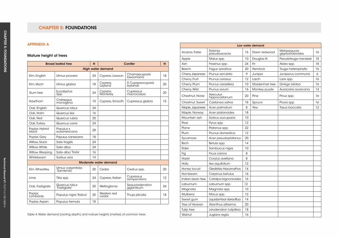
CHAPTER 5: FOUNDATIONSCH
APTER 5: FO
UN
DA
TION
STe
ch
nic
al M
anu
al V
7: TS-011a-7.00-180814
Broad leafed tree H Conifer H
High water demand
Elm, English ulmus procera 24 Cypress, Lawson Chamaecyparis lawsoniana 18
Elm, Wych ulmus glabra 18 Cypress, Leyland
x Cupressocyparis leylandii 20
Gum tree EucalyptusSpp. 24 Cypress,
MontereyCupressus macrocarpa 20
Hawthorn Crataegus monogyna 10 Cypress, Smooth Cupressus glabra 15
Oak, English quercus robur 24
Oak, Holm quercus ilex 16
Oak, Red quercus rubra 20
Oak, Turkey quercus cerris 24
Poplar, Hybrid black
Populus x euramericana 28
Poplar, Grey Populus canescens 18
Willow, Srack Salix fragilis 24
Willow, White Salix alba 24
Willow, Weeping Salix alba ‘Tristis’ 16
Whitebeam Sorbus aria 14
Moderate water demand
Elm, Wheatley ulmus carpinifolia ‘Sarniensis’ 20 Cedar Cedrus spp. 20
Lime Tilia spp. 24 Cypress, Italian Cupressus sempervirens 12
Oak, Fastigiate quercus robur ‘Fastigiata’ 20 Wellingtonia Sequoiadendron
giganteum 24
Poplar, Lombardy Populus nigra ‘Italica’ 25 Western red
cedar Thuja plicata 18
Poplar, Aspen Populus tremula 18
Low water demand
Acacia, False Robinia pseudoacacia 16 Dawn redwood Metasequoia
glyptostroboides 16
Apple Malus spp. 10 Douglas fir Pseudotsuga menziesii 18
Ash Fraxinus spp. 24 Fir Abies spp. 18
Beech Fagus sylvatica 20 Hemlock Tsuga heterophylla 16
Cherry, Japanese Prunus serrulata 9 Juniper Juniperus communis 6
Cherry, Fruit Prunus cerasus 12 Larch Larix spp. 16
Cherry, Plum Prunus cerasifera 10 Maidenhair tree Ginkgo biloba 16
Cherry, Wild Prunus avium 16 Monkey puzzle Auracaria auracana 14
Chestnut, Horse Aesculus hippocastanum 20 Pine Pinus spp. 16
Chestnut, Sweet Castanea sativa 18 Spruce Picea spp. 16
Maple, Japanese Acer palmatum 8 yew Taxus baccata 12
Maple, Norway Acer platanoides 18
Mountain ash Sorbus aucuparia 10
Pear Pyrus spp. 12
Plane Platanus spp. 22
Plum Prunus domestica 12
Sycamore Acer pseudoplatanus 20
Birch Betula spp. 14
Elder Sambucus nigra 10
Fig Ficus carica 8
Hazel Corylus avellana 8
Holly Ilex aquifolium 12
Honey locust Gledistsia triacanathos 14
Hornbeam Carpinus betulus 16
Indian bean tree Catalpa bignonioides 16
Laburnum Laburnum spp. 12
Magnolia Magnolia spp. 10
Mulberry Morus spp. 12
Sweet gum Liquidambar styraciflua 14
Tree of Heaven Ailanthus altissima 20
Tulip tree Liriodendron tulipifera 18
Walnut Juglans regia 16Table 4: Water demand (rooting depth) and mature heights (metres) of common trees
APPenDix A
Mature height of trees

Tec
hn
ica
l Ma
nua
l V6: TS-011a
-6.00-010413Te
ch
nic
al M
anu
al V
7: TS-011a-7.00-180814
FUNCTIONAL REQUIREMENTS
77
5.3 sTriP AnD MAss fiLLeD founDATions
Workmanshipi. All workmanship must be within the tolerances defined in Chapter 1
of this Manual.
ii. All work is to be carried out by a technically competent person in
a workmanlike manner.
iii. Strip foundations should be of a suitable depth in order to achieve
a satisfactory level of performance.
Materialsi. All materials should be stored correctly in a manner that will not cause
damage or deterioration of the product.
ii. All materials, products and building systems shall be appropriate and
suitable for their intended purpose.
iii. The structure shall, unless specifically agreed otherwise with the
Warranty provider, have a life of not less than 60 years. Individual
components and assemblies, not integral to the structure, may have
a lesser durability, but not in any circumstances less than 15 years.
Designi. The design and specifications shall provide a clear indication of the
design intent and demonstrate a satisfactory level of performance.
ii. Structural elements outside the parameters of regional Approved
Documents must be supported by structural calculations provided by
a suitably qualified expert.
iii. Strip foundations must meet the relevant Building Regulations, British
Standards, Eurocodes and other statutory requirements.
CHAPTer 5
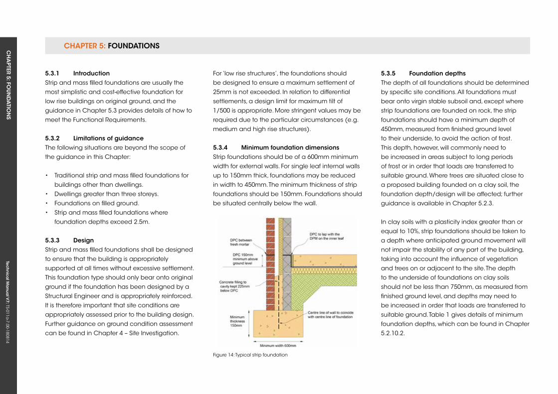
CHAPTER 5: FOUNDATIONSCH
APTER 5: FO
UN
DA
TION
STe
ch
nic
al M
anu
al V
7: TS-011a-7.00-180814
For ‘low rise structures’, the foundations should
be designed to ensure a maximum settlement of
25mm is not exceeded. In relation to differential
settlements, a design limit for maximum tilt of
1/500 is appropriate. More stringent values may be
required due to the particular circumstances (e.g.
medium and high rise structures).
5.3.4 Minimum foundation dimensionsStrip foundations should be of a 600mm minimum
width for external walls. For single leaf internal walls
up to 150mm thick, foundations may be reduced
in width to 450mm. The minimum thickness of strip
foundations should be 150mm. Foundations should
be situated centrally below the wall.
Figure 14: Typical strip foundation
5.3.1 introductionStrip and mass filled foundations are usually the
most simplistic and cost-effective foundation for
low rise buildings on original ground, and the
guidance in Chapter 5.3 provides details of how to
meet the Functional Requirements.
5.3.2 Limitations of guidanceThe following situations are beyond the scope of
the guidance in this Chapter:
• Traditional strip and mass filled foundations for
buildings other than dwellings.
• Dwellings greater than three storeys.
• Foundations on filled ground.
• Strip and mass filled foundations where
foundation depths exceed 2.5m.
5.3.3 DesignStrip and mass filled foundations shall be designed
to ensure that the building is appropriately
supported at all times without excessive settlement.
This foundation type should only bear onto original
ground if the foundation has been designed by a
Structural Engineer and is appropriately reinforced.
It is therefore important that site conditions are
appropriately assessed prior to the building design.
Further guidance on ground condition assessment
can be found in Chapter 4 – Site Investigation.
5.3.5 foundation depthsThe depth of all foundations should be determined
by specific site conditions. All foundations must
bear onto virgin stable subsoil and, except where
strip foundations are founded on rock, the strip
foundations should have a minimum depth of
450mm, measured from finished ground level
to their underside, to avoid the action of frost.
This depth, however, will commonly need to
be increased in areas subject to long periods
of frost or in order that loads are transferred to
suitable ground. Where trees are situated close to
a proposed building founded on a clay soil, the
foundation depth/design will be affected; further
guidance is available in Chapter 5.2.3.
In clay soils with a plasticity index greater than or
equal to 10%, strip foundations should be taken to
a depth where anticipated ground movement will
not impair the stability of any part of the building,
taking into account the influence of vegetation
and trees on or adjacent to the site. The depth
to the underside of foundations on clay soils
should not be less than 750mm, as measured from
finished ground level, and depths may need to
be increased in order that loads are transferred to
suitable ground. Table 1 gives details of minimum
foundation depths, which can be found in Chapter
5.2.10.2.
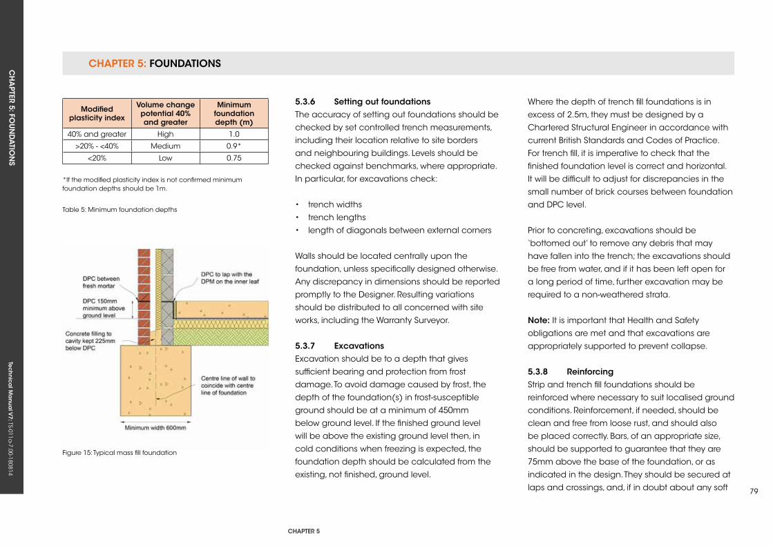
CHAPTER 5: FOUNDATIONSCH
APTER 5: FO
UN
DA
TION
STe
ch
nic
al M
anu
al V
7: TS-011a-7.00-180814
CHAPTER 5
79
Modified plasticity index
volume change potential 40% and greater
Minimum foundation depth (m)
40% and greater High 1.0
>20% - <40% Medium 0.9*
<20% Low 0.75
*If the modified plasticity index is not confirmed minimum foundation depths should be 1m.
Table 5: Minimum foundation depths
Figure 15: Typical mass fill foundation
5.3.6 setting out foundationsThe accuracy of setting out foundations should be
checked by set controlled trench measurements,
including their location relative to site borders
and neighbouring buildings. Levels should be
checked against benchmarks, where appropriate.
In particular, for excavations check:
• trench widths
• trench lengths
• length of diagonals between external corners
Walls should be located centrally upon the
foundation, unless specifically designed otherwise.
Any discrepancy in dimensions should be reported
promptly to the Designer. Resulting variations
should be distributed to all concerned with site
works, including the Warranty Surveyor.
5.3.7 excavationsExcavation should be to a depth that gives
sufficient bearing and protection from frost
damage. To avoid damage caused by frost, the
depth of the foundation(s) in frost-susceptible
ground should be at a minimum of 450mm
below ground level. If the finished ground level
will be above the existing ground level then, in
cold conditions when freezing is expected, the
foundation depth should be calculated from the
existing, not finished, ground level.
Where the depth of trench fill foundations is in
excess of 2.5m, they must be designed by a
Chartered Structural Engineer in accordance with
current British Standards and Codes of Practice.
For trench fill, it is imperative to check that the
finished foundation level is correct and horizontal.
It will be difficult to adjust for discrepancies in the
small number of brick courses between foundation
and DPC level.
Prior to concreting, excavations should be
‘bottomed out’ to remove any debris that may
have fallen into the trench; the excavations should
be free from water, and if it has been left open for
a long period of time, further excavation may be
required to a non-weathered strata.
note: It is important that Health and Safety
obligations are met and that excavations are
appropriately supported to prevent collapse.
5.3.8 reinforcingStrip and trench fill foundations should be
reinforced where necessary to suit localised ground
conditions. Reinforcement, if needed, should be
clean and free from loose rust, and should also
be placed correctly. Bars, of an appropriate size,
should be supported to guarantee that they are
75mm above the base of the foundation, or as
indicated in the design. They should be secured at
laps and crossings, and, if in doubt about any soft
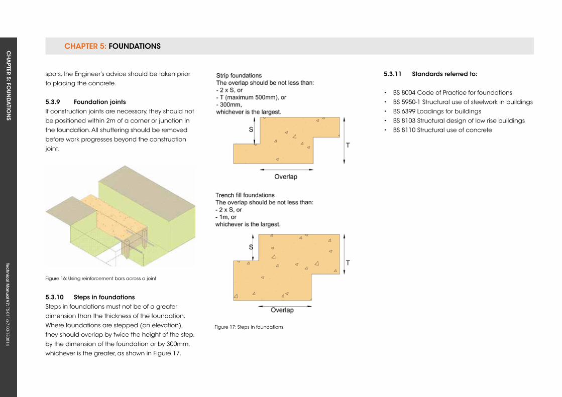
CHAPTER 5: FOUNDATIONSCH
APTER 5: FO
UN
DA
TION
STe
ch
nic
al M
anu
al V
7: TS-011a-7.00-180814
Figure 16: using reinforcement bars across a joint
Figure 17: Steps in foundations
spots, the Engineer’s advice should be taken prior
to placing the concrete.
5.3.9 foundation jointsIf construction joints are necessary, they should not
be positioned within 2m of a corner or junction in
the foundation. All shuttering should be removed
before work progresses beyond the construction
joint.
5.3.10 steps in foundationsSteps in foundations must not be of a greater
dimension than the thickness of the foundation.
Where foundations are stepped (on elevation),
they should overlap by twice the height of the step,
by the dimension of the foundation or by 300mm,
whichever is the greater, as shown in Figure 17.
5.3.11 standards referred to:
• BS 8004 Code of Practice for foundations
• BS 5950-1 Structural use of steelwork in buildings
• BS 6399 Loadings for buildings
• BS 8103 Structural design of low rise buildings
• BS 8110 Structural use of concrete
Tec
hn
ica
l Ma
nua
l V6: TS-011a
-6.00-010413Te
ch
nic
al M
anu
al V
7: TS-011a-7.00-180814
FUNCTIONAL REQUIREMENTS
81
5.4 PiLeD founDATions
Workmanshipi. All workmanship must be within the tolerances defined in Chapter 1
of this Manual.
ii. All work is to be carried out by a technically competent person in
a workmanlike manner.
iii. Pile foundations schemes must be tested to confirm that the
installation meets the design requirements.
Materialsi. All materials should be stored correctly in a manner that will not cause
damage or deterioration of the product.
ii. All materials, products and building systems shall be appropriate and
suitable for their intended purpose.
iii. The structure shall, unless specifically agreed otherwise with the
Warranty provider, have a life of not less than 60 years. Individual
components and assemblies, not integral to the structure, may have a
lesser durability, but not in any circumstances less than 15 years.
Designi. The design and specifications shall provide a clear indication of the
design intent and demonstrate a satisfactory level of performance.
ii. Piled foundation designs must be supported by structural calculations
provided by a suitably qualified expert. Calculations for full piling
systems must be provided by, or endorsed by, the piling manufacturer.
iii. Piled foundations must meet the relevant Building Regulations, British
Standards, Eurocodes and other statutory requirements.
CHAPTer 5
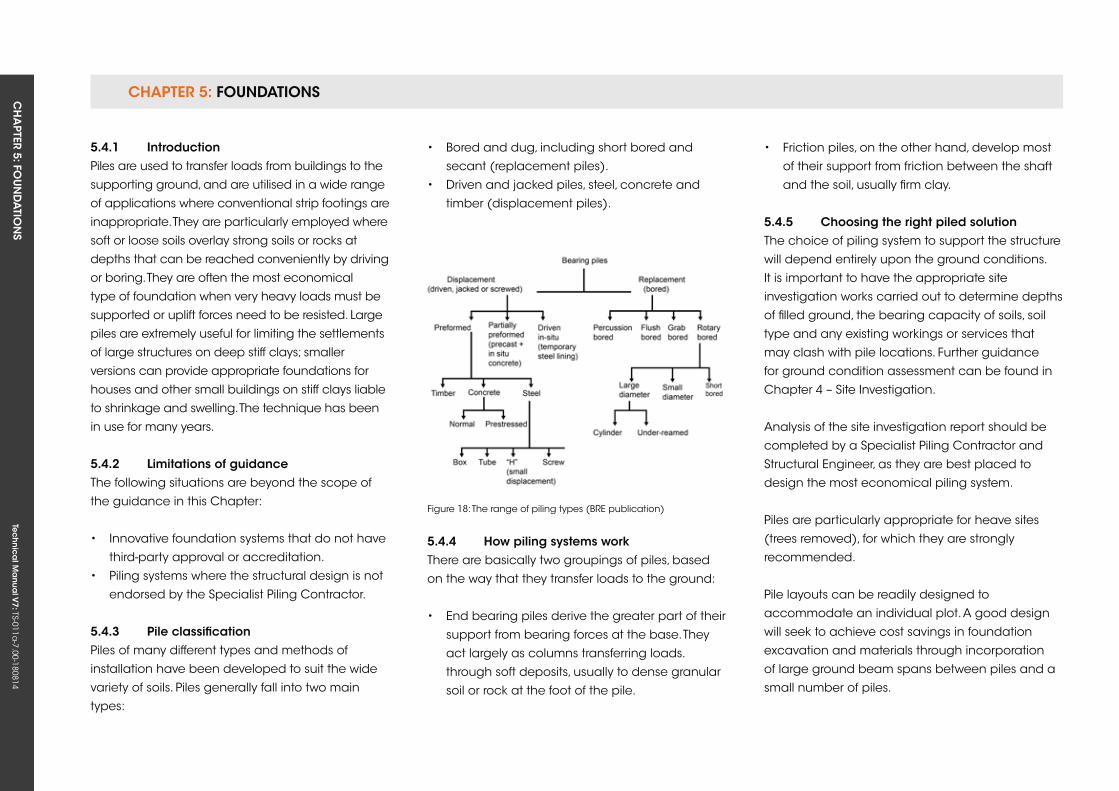
CHAPTER 5: FOUNDATIONSCH
APTER 5: FO
UN
DA
TION
STe
ch
nic
al M
anu
al V
7: TS-011a-7.00-180814
Figure 18: The range of piling types (BRE publication)
5.4.1 introductionPiles are used to transfer loads from buildings to the
supporting ground, and are utilised in a wide range
of applications where conventional strip footings are
inappropriate. They are particularly employed where
soft or loose soils overlay strong soils or rocks at
depths that can be reached conveniently by driving
or boring. They are often the most economical
type of foundation when very heavy loads must be
supported or uplift forces need to be resisted. Large
piles are extremely useful for limiting the settlements
of large structures on deep stiff clays; smaller
versions can provide appropriate foundations for
houses and other small buildings on stiff clays liable
to shrinkage and swelling. The technique has been
in use for many years.
5.4.2 Limitations of guidanceThe following situations are beyond the scope of
the guidance in this Chapter:
• Innovative foundation systems that do not have
third-party approval or accreditation.
• Piling systems where the structural design is not
endorsed by the Specialist Piling Contractor.
5.4.3 Pile classificationPiles of many different types and methods of
installation have been developed to suit the wide
variety of soils. Piles generally fall into two main
types:
• Bored and dug, including short bored and
secant (replacement piles).
• Driven and jacked piles, steel, concrete and
timber (displacement piles).
5.4.4 How piling systems workThere are basically two groupings of piles, based
on the way that they transfer loads to the ground:
• End bearing piles derive the greater part of their
support from bearing forces at the base. They
act largely as columns transferring loads.
through soft deposits, usually to dense granular
soil or rock at the foot of the pile.
• Friction piles, on the other hand, develop most
of their support from friction between the shaft
and the soil, usually firm clay.
5.4.5 Choosing the right piled solutionThe choice of piling system to support the structure
will depend entirely upon the ground conditions.
It is important to have the appropriate site
investigation works carried out to determine depths
of filled ground, the bearing capacity of soils, soil
type and any existing workings or services that
may clash with pile locations. Further guidance
for ground condition assessment can be found in
Chapter 4 – Site Investigation.
Analysis of the site investigation report should be
completed by a Specialist Piling Contractor and
Structural Engineer, as they are best placed to
design the most economical piling system.
Piles are particularly appropriate for heave sites
(trees removed), for which they are strongly
recommended.
Pile layouts can be readily designed to
accommodate an individual plot. A good design
will seek to achieve cost savings in foundation
excavation and materials through incorporation
of large ground beam spans between piles and a
small number of piles.
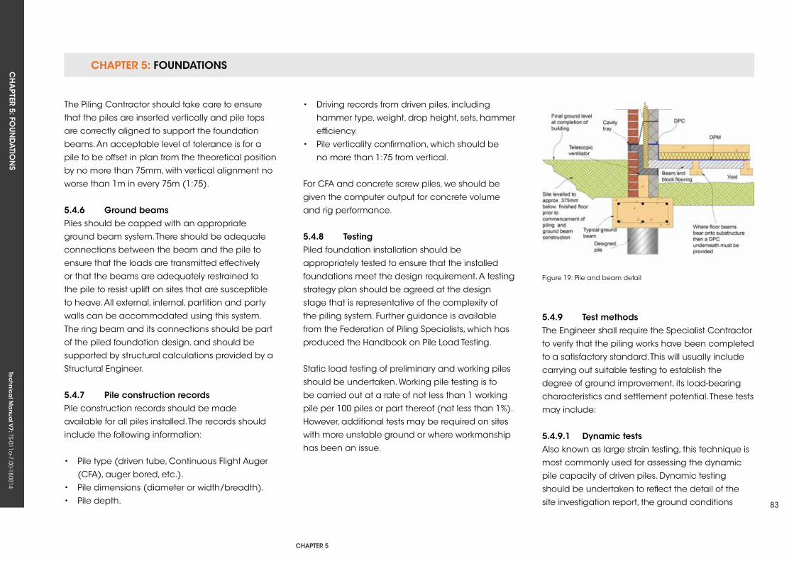
CHAPTER 5: FOUNDATIONSCH
APTER 5: FO
UN
DA
TION
STe
ch
nic
al M
anu
al V
7: TS-011a-7.00-180814
CHAPTER 5
83
Figure 19: Pile and beam detail
The Piling Contractor should take care to ensure
that the piles are inserted vertically and pile tops
are correctly aligned to support the foundation
beams. An acceptable level of tolerance is for a
pile to be offset in plan from the theoretical position
by no more than 75mm, with vertical alignment no
worse than 1m in every 75m (1:75).
5.4.6 ground beamsPiles should be capped with an appropriate
ground beam system. There should be adequate
connections between the beam and the pile to
ensure that the loads are transmitted effectively
or that the beams are adequately restrained to
the pile to resist uplift on sites that are susceptible
to heave. All external, internal, partition and party
walls can be accommodated using this system.
The ring beam and its connections should be part
of the piled foundation design, and should be
supported by structural calculations provided by a
Structural Engineer.
5.4.7 Pile construction recordsPile construction records should be made
available for all piles installed. The records should
include the following information:
• Pile type (driven tube, Continuous Flight Auger
(CFA), auger bored, etc.).
• Pile dimensions (diameter or width/breadth).
• Pile depth.
• Driving records from driven piles, including
hammer type, weight, drop height, sets, hammer
efficiency.
• Pile verticality confirmation, which should be
no more than 1:75 from vertical.
For CFA and concrete screw piles, we should be
given the computer output for concrete volume
and rig performance.
5.4.8 TestingPiled foundation installation should be
appropriately tested to ensure that the installed
foundations meet the design requirement. A testing
strategy plan should be agreed at the design
stage that is representative of the complexity of
the piling system. Further guidance is available
from the Federation of Piling Specialists, which has
produced the Handbook on Pile Load Testing.
Static load testing of preliminary and working piles
should be undertaken. Working pile testing is to
be carried out at a rate of not less than 1 working
pile per 100 piles or part thereof (not less than 1%).
However, additional tests may be required on sites
with more unstable ground or where workmanship
has been an issue.
5.4.9 Test methodsThe Engineer shall require the Specialist Contractor
to verify that the piling works have been completed
to a satisfactory standard. This will usually include
carrying out suitable testing to establish the
degree of ground improvement, its load-bearing
characteristics and settlement potential. These tests
may include:
5.4.9.1 Dynamic testsAlso known as large strain testing, this technique is
most commonly used for assessing the dynamic
pile capacity of driven piles. Dynamic testing
should be undertaken to reflect the detail of the
site investigation report, the ground conditions
CHAPTER 5: FOUNDATIONSCH
APTER 5: FO
UN
DA
TION
STe
ch
nic
al M
anu
al V
7: TS-011a-7.00-180814
and the factor of safety applied to the pile design.
Please submit this information at the time of the
Warranty application and prior to commencement
on site.
5.4.9.2 integrity testsAlso known as low strain testing, there are two types
of tests used solely for assessing pile integrity:
• Cross hole sonic logging
• Pulse echo
For integrity testing of continuous Flight Auger Piles,
100% of the piles should be tested.
5.4.9.3 negative skin frictionWhere piles pass through ground that may
consolidate or change in volume (e.g. due to
a change in water table or loading due to the
raising of levels), the effects of negative skin friction
should be taken into account. The capacity of
the pile to resist the additional compressive and
tensile stresses should be checked at critical cross
sections.
5.4.10 relevant standards and guidance Documents:• BS 8004 Code of Practice for foundations
• BS EN 1997 – 1 Eurocode 7
• BS EN 1997 – 2 Eurocode 7
• BS 5950-1 Structural use of steelwork in buildings
• BS 6399 Loadings for buildings
• BS 8103 Structural design of low rise buildings
• BS 8110 Structural use of concrete
• Piling Good Practice Guide
(please refer to our website for further details)
Tec
hn
ica
l Ma
nua
l V6: TS-011a
-6.00-010413Te
ch
nic
al M
anu
al V
7: TS-011a-7.00-180814
FUNCTIONAL REQUIREMENTS
85
5.5 rAfT founDATions
Workmanshipi. All workmanship must be within the tolerances defined in Chapter 1
of this Manual.
ii. All work is to be carried out by a technically competent person in a
workmanlike manner.
Materialsi. All materials should be stored correctly in a manner that will not cause
damage or deterioration of the product.
ii. All materials, products and building systems shall be appropriate and
suitable for their intended purpose.
iii. The structure shall, unless specifically agreed otherwise with the
Warranty provider, have a life of not less than 60 years. Individual
components and assemblies, not integral to the structure, may have a
lesser durability, but not in any circumstances less than 15 years.
Designi. The design and specifications shall provide a clear indication of the
design intent and demonstrate a satisfactory level of performance.
ii. Raft foundation designs must be supported by structural calculations
provided by a suitably qualified expert.
iii. Raft foundation design and construction must meet the relevant
Building Regulations, British Standards, Eurocodes and other statutory
requirements.
CHAPTer 5
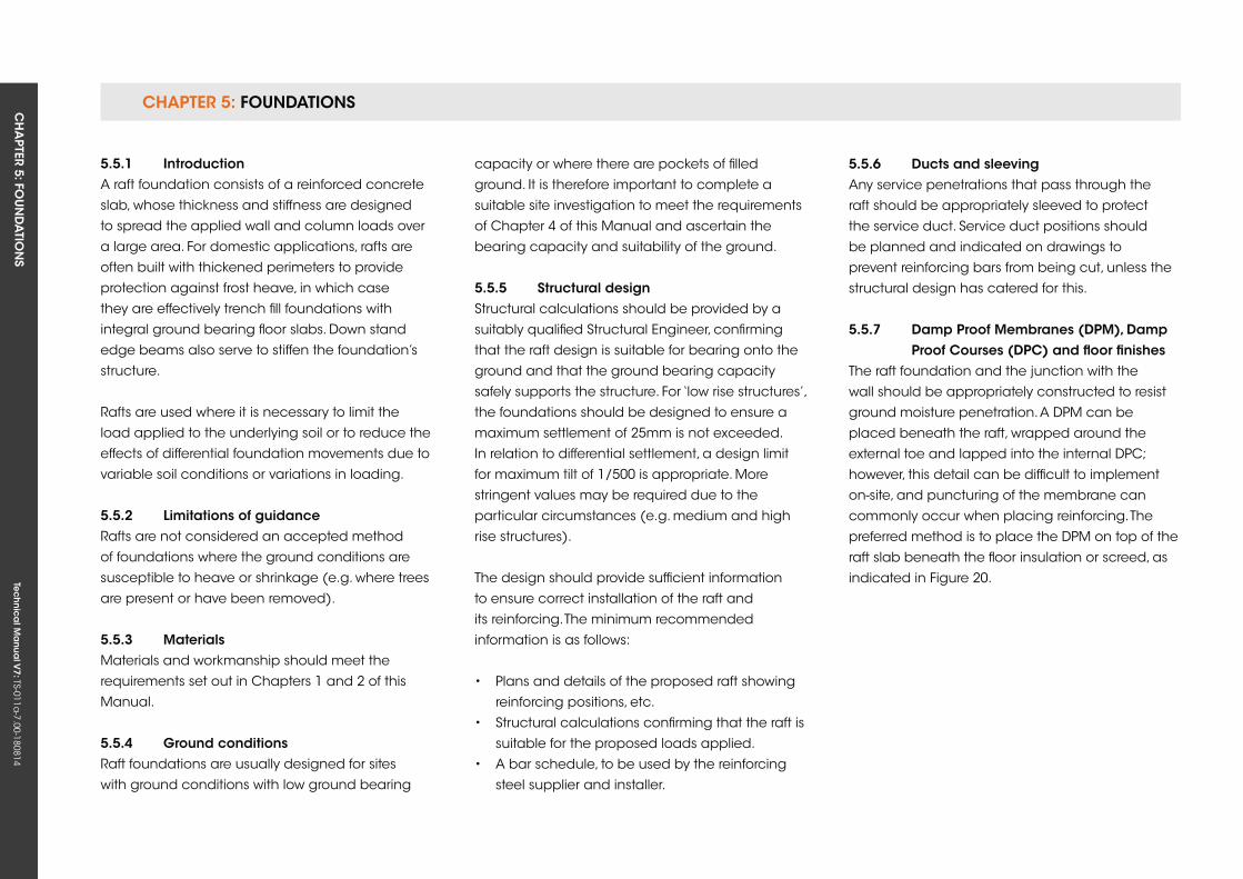
CHAPTER 5: FOUNDATIONSCH
APTER 5: FO
UN
DA
TION
STe
ch
nic
al M
anu
al V
7: TS-011a-7.00-180814
5.5.1 introductionA raft foundation consists of a reinforced concrete
slab, whose thickness and stiffness are designed
to spread the applied wall and column loads over
a large area. For domestic applications, rafts are
often built with thickened perimeters to provide
protection against frost heave, in which case
they are effectively trench fill foundations with
integral ground bearing floor slabs. Down stand
edge beams also serve to stiffen the foundation’s
structure.
Rafts are used where it is necessary to limit the
load applied to the underlying soil or to reduce the
effects of differential foundation movements due to
variable soil conditions or variations in loading.
5.5.2 Limitations of guidanceRafts are not considered an accepted method
of foundations where the ground conditions are
susceptible to heave or shrinkage (e.g. where trees
are present or have been removed).
5.5.3 MaterialsMaterials and workmanship should meet the
requirements set out in Chapters 1 and 2 of this
Manual.
5.5.4 ground conditionsRaft foundations are usually designed for sites
with ground conditions with low ground bearing
capacity or where there are pockets of filled
ground. It is therefore important to complete a
suitable site investigation to meet the requirements
of Chapter 4 of this Manual and ascertain the
bearing capacity and suitability of the ground.
5.5.5 structural designStructural calculations should be provided by a
suitably qualified Structural Engineer, confirming
that the raft design is suitable for bearing onto the
ground and that the ground bearing capacity
safely supports the structure. For ‘low rise structures’,
the foundations should be designed to ensure a
maximum settlement of 25mm is not exceeded.
In relation to differential settlement, a design limit
for maximum tilt of 1/500 is appropriate. More
stringent values may be required due to the
particular circumstances (e.g. medium and high
rise structures).
The design should provide sufficient information
to ensure correct installation of the raft and
its reinforcing. The minimum recommended
information is as follows:
• Plans and details of the proposed raft showing
reinforcing positions, etc.
• Structural calculations confirming that the raft is
suitable for the proposed loads applied.
• A bar schedule, to be used by the reinforcing
steel supplier and installer.
5.5.6 Ducts and sleevingAny service penetrations that pass through the
raft should be appropriately sleeved to protect
the service duct. Service duct positions should
be planned and indicated on drawings to
prevent reinforcing bars from being cut, unless the
structural design has catered for this.
5.5.7 Damp Proof Membranes (DPM), Damp Proof Courses (DPC) and floor finishesThe raft foundation and the junction with the
wall should be appropriately constructed to resist
ground moisture penetration. A DPM can be
placed beneath the raft, wrapped around the
external toe and lapped into the internal DPC;
however, this detail can be difficult to implement
on-site, and puncturing of the membrane can
commonly occur when placing reinforcing. The
preferred method is to place the DPM on top of the
raft slab beneath the floor insulation or screed, as
indicated in Figure 20.
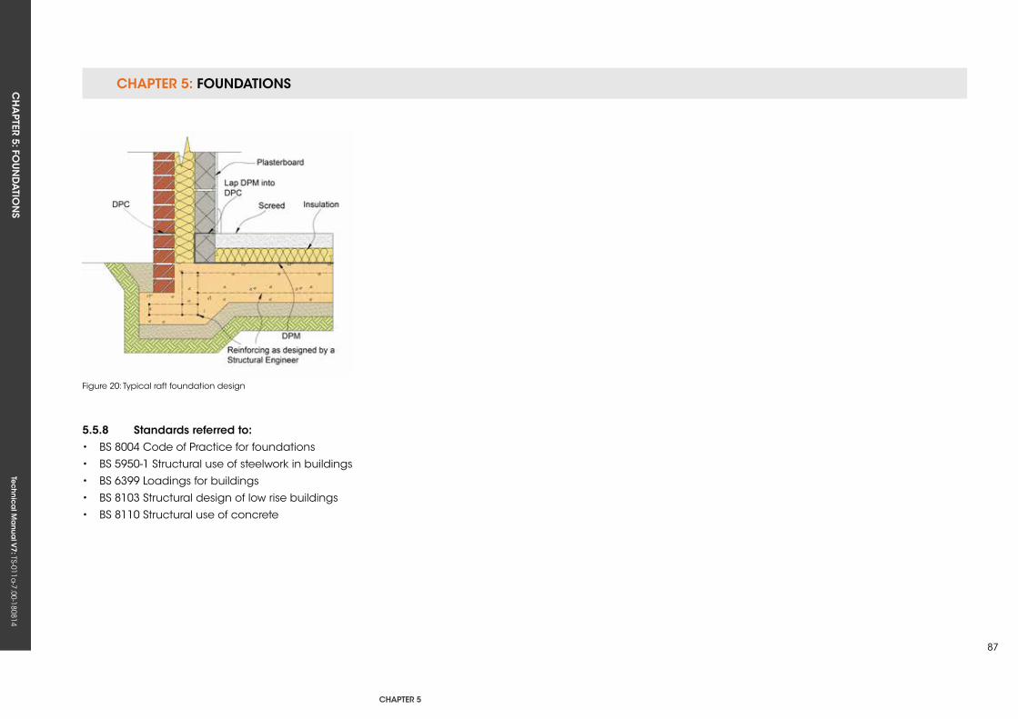
CHAPTER 5: FOUNDATIONSCH
APTER 5: FO
UN
DA
TION
STe
ch
nic
al M
anu
al V
7: TS-011a-7.00-180814
CHAPTER 5
87
Figure 20: Typical raft foundation design
5.5.8 standards referred to:• BS 8004 Code of Practice for foundations
• BS 5950-1 Structural use of steelwork in buildings
• BS 6399 Loadings for buildings
• BS 8103 Structural design of low rise buildings
• BS 8110 Structural use of concrete

Tec
hn
ica
l Ma
nua
l V6: TS-011a
-6.00-010413Te
ch
nic
al M
anu
al V
7: TS-011a-7.00-180814

CH
APTER 6: SU
BSTRUC
TURE
Tec
hn
ica
l Ma
nua
l V7: TS-011a
-7.00-180814
CHAPTER 6
89
CHAPTer 6: suBsTruCTure
ConTenTs
6.1 BASEMENTS
6.2 WALLS BELOW GROuND
6.3 DAMP PROOFING
6.4 GROuND FLOORS

Tec
hn
ica
l Ma
nua
l V6: TS-011a
-6.00-010413Te
ch
nic
al M
anu
al V
7: TS-011a-7.00-180814
FUNCTIONAL REQUIREMENTS
DefinitionFor the purposes of this Chapter, a basement is defined as a storey or
storeys of a building that is constructed partially or entirely below ground.
Workmanshipi. All workmanship must be within the tolerances defined in Chapter 1
of this Manual.
ii. All work is to be carried out by a technically competent person in
a workmanlike manner.
iii. Certification is required for any work completed by an approved
installer.
Materialsi. All materials should be stored correctly in a manner that will not cause
damage or deterioration of the product.
ii. All materials, products and building systems shall be appropriate and
suitable for their intended purpose.
iii. The structure shall, unless specifically agreed otherwise with the
Warranty provider, have a life of not less than 60 years. Individual
components and assemblies, not integral to the structure, may have a
lesser durability, but not in any circumstances less than 15 years.
6.1 BAseMenTs
Designi. Design and specifications shall provide a clear indication of the
design intent and demonstrate a satisfactory level of performance.
ii. Basements shall be appropriately designed to ensure that they
adequately provide a suitable barrier against contaminants, ground
gases and ground water.
iii. Basement design and construction must be supported by structural
calculations provided by a suitably qualified expert.
iv. Design details of the basement waterproofing techniques must be
provided prior to commencement onsite.
v. Basements must meet the relevant Building Regulations, British
Standards, Eurocodes and other statutory requirements.
vi. All basements must be designed and constructed to a minimum of
Grade 2 standard as defined in BS 8102.
vii. The basement design should be completed by a suitably qualified
Waterproofing Design Specialist. The Waterproofing Specialist must
take responsibility for the design liability of the waterproofing and have
appropriate professional indemnity cover which covers their business
activities. They must also have an understanding of hydrology and soil
mechanics and hold a relevant professional qualification (i.e. Certified
Surveyor in Structural Waterproofing (CSSW) or similar).
CHAPTER 6: SUBSTRUCTURE CH
APTER 6: SU
BSTRUC
TURE
Tec
hn
ica
l Ma
nua
l V7: TS-011a
-7.00-180814
CHAPTER 6
91
6.1.1 introductionThis Chapter provides guidance on the
requirements associated with the design and
construction of basements and other below
ground structures. Principally, this concerns
the process by which the risk of ground water
penetration is appraised and addressed, so
that problems associated with penetration do
not occur, while consideration is also given to
economic construction.
This process and rationale is primarily detailed
within BS 8102 (2009) Code of Practice for
protection of below ground structures against
water from the ground (and other associated
design guides). However, further practical
guidance on this and compliance with Warranty
requirements is included herein.
6.1.2 Limitations of guidanceThis document is not intended as a standalone
design guide, and does not include the full
detail of what must be considered to comply
with BS 8102. See ‘References’ for details of other
associated design guides.
It must also be noted that structural waterproofing
design and geotechnical investigation are
specialist fields, and while general guidance is
provided, advice must be sought from suitably
experienced parties. Appropriate structural design
must be undertaken by a Chartered Structural
Engineer.
6.1.3 general principle of waterproofing designThe approach detailed within BS 8102 involves
assessment of a given site to determine the
characteristics that influence risk. With the benefit
of knowledge gained through this investigation
and assessment, suitable designs for dealing with
ground water, gases and contaminants can then
be devised and constructed.
6.1.4 Design responsibility Production of a suitable design is one of the most
important aspects of achieving a successful
outcome, where the required standard of
environment is created within the basement space
and maintained in the long term. A common
assumption in waterproofing is that workmanship
is the most ‘critical factor’, and while this is
undeniably important, the highest standards of
workmanship will not make-up for inadequate
design; hence, correct design is the first step in
achieving the desired outcome.
To this end, BS 8102 includes a section on the
‘design team’, which states that the advice of a
Geotechnical Specialist be sought for assessment
of the geology and hydrogeology, and that a
Waterproofing Specialist be included as part of the
design team from the earliest stages, so that an
integrated and practical waterproofing solution is
created.
The need for a dedicated Waterproofing Specialist
within the design team is intended to reduce the
incidence of issues where systems are designed
without following the advice and considerations
detailed within BS 8102 and associated design
guides.
Such scenarios may occur where Project Designers
take on the role of Waterproofing Designer
without sufficient reference to the stated guides,
commonly relying on standard design details
and without considering all appropriate factors.
Please refer to BS 8102 for a list of requirements
that a Designer must meet in order to fulfil the
Waterproofing Designer role. Designers must also
carry professional indemnity insurance cover
appropriate to the project.
It must be noted that waterproofing product
manufacturer ‘standard details’ typically disclaim
design responsibility, so it is incumbent on the
Waterproofing Designer to ensure that such details
are correct and appropriate for the site and
structure, or offer suitable variation.
The early involvement of a Waterproofing Designer
is an important consideration because the
CHAPTER 6: SUBSTRUCTURE CH
APTER 6: SU
BSTRUC
TURE
Tec
hn
ica
l Ma
nua
l V7: TS-011a
-7.00-180814
waterproofing design typically has an influence
on elements of the structural and/or architectural
design. Early involvement allows the waterproofing
to be duly considered in association with these
other aspects, and prevents situations where
design fees are increased as a result of necessary
redesign, or where waterproofing is compromised
by working within the constraints of an ill-
considered structure relative to achieving the
required standard of environment.
Designers must have ongoing involvement during
the build, maintaining good communication with
site management and providing supervision and
guidance wherever necessary.
6.1.5 site and risk assessmentThe degree of water present within the ground,
and the propensity for waterlogging to occur over
the lifetime of a structure, is a principal driver in
assessing risk and the degree of waterproofing
required. Simplistically, if a basement is constructed
into a permanent high water table, then the
degree of protection will necessarily be greater
than a similar structure constructed into a
generally dry site.
Assessment of a site must be based on the results
of the site investigation and other site-specific
factors. Seasonal variations in the water table must
be accounted for unless long-term monitoring is
undertaken. However, even where standing water
levels are not noted during such pre-start site
investigation, the drainage characteristics of the
ground must receive particular attention. Soils with
low permeability represent a risk of waterlogging
or encouraging a ‘perched water table’, where
water stands temporarily or permanently within
the ground against a structure, and arguably this
affects more properties with basements than the
true water table level.
Other factors, such as topography and orientation,
may have a bearing on the propensity for
pressure to come to bear, and should also
receive consideration. Further guidance on the
drainage characteristics associated with different
types of ground is included within the Basement
Information Centre publication Basements:
Waterproofing – General Guidance to BS 8102:
2009.
Ground gases and contaminants must also be
considered within the risk assessment. It must be
noted that while the site investigation forms part of
what guides the waterproofing design, an equally
important consideration is the intended use of the
space and implicit consequences in the event
that water penetration occurs. For example, in
properties where the consequences of penetration
would be severe, such as in habitable space,
suitably low-risk methods must be provided.
Furthermore, whilst in theory it could be assumed
that, based upon a site investigation, the risk
of water pressure ever occurring is low, BS 8102
advises that consideration is given to the effects
of climate change and burst water mains and
sewers, as well as stating that it should be assumed
that there is risk of waterlogging “even where site
examination indicated dry conditions”.
In summary, the site investigation guides the
design, but it should never be assumed that some
degree of water pressure will not occur.
Furthermore, and particularly if no site investigation
has been undertaken or there is reasonable doubt
as to ground water conditions, pressure to the
full height of the below ground structure must be
assumed at some point in the life of the structure.
The Warranty Surveyor may request a copy of the
Site Investigation Report, Designer’s Risk Assessment
and associated design rationale.
6.1.6 Water-resisting designThe principle of this is to consider and design for
the pressures that the structure/waterproofing
must resist based upon the site investigation and
risk assessment detailed above. However, it also
concerns the means by which the degree of water
in the ground can be influenced by design.
CHAPTER 6: SUBSTRUCTURE CH
APTER 6: SU
BSTRUC
TURE
Tec
hn
ica
l Ma
nua
l V7: TS-011a
-7.00-180814
CHAPTER 6
93
6.1.6.1 structural resistanceThe ability of the structure to provide resistance
to the penetration of water has a bearing upon
all forms of waterproofing. Retaining walls in plain
or reinforced masonry provide comparatively
little resistance to the penetration of water under
pressure because of the crack pattern associated
with the degree of joints (mortar beds) present.
The degree of water excluded by concrete
elements (walls and slab) is influenced by the
nature of the design and construction. While
concrete itself is relatively impermeable, the
degree to which water is excluded will be greatly
influenced by crack sizes and the detailing of
construction joints and service penetrations.
6.1.6.2 exclusion of surface waterSurfaces external of the basement structure
at ground level can act to limit or attenuate
penetration into vulnerable positions, i.e. the more
permeable excavated and backfilled ground
directly around the basement structure. The
inclusion of surface and cut-off drains that remove
standing water away from the vulnerable areas are
also of benefit.
6.1.6.3 sub-surface drainageThe use of land drainage can act to remove water
from around the structure, thus alleviating pressure
and reducing risk accordingly.
The use of land drainage is not viable on all
sites, examples being where there is no available
location to discharge collected ground water,
or where high water tables and permeable
ground conditions make it impractical to remove
sufficiently the quantities of water present. A
Geotechnical Specialist and/or Waterproofing
Specialist can advise further in this respect.
Notwithstanding such conditions, the provision of
effective land drains is often an economic means
of greatly reducing risk, and must be included
where viable.
The following considerations apply:
• Perforated land drains must be surrounded in
clean graded stone and wrapped in a suitable
geo-textile filter fabric to reduce the risk of
clogging. This is particularly important in fine
granular and clay soils where land drains are
susceptible to clogging.
• Rodding points must be included (ideally at
changes in direction) to facilitate maintenance,
which will allow the system to function in the
long term. This maintenance should be
undertaken at suitable intervals (annually as a
minimum), with the detail of this being written
into the documentation passed to homeowners.
• Land drains must link to a reliable point
of discharge. Where sump pump systems
are employed, the implications of power cuts
should be considered in that land drains may
in such scenarios not function as intended. The
effectiveness of battery back-up systems, where
employed in sumps servicing land drains,
should be considered in relation to assessment
of the likely degree of ground water.
It is not unknown for issues of waterproofing failure
to occur where land drains (that form part of the
Waterproofing System) are linked into soakaways. The
limitation on soakaways is that, depending on the
nature of the ground, they may become saturated
(similar to the ground around a basement), meaning
that no more water can be accepted, with pressure
subsequently coming to bear upon the structure. In
such cases, the soakaway often also accepts water
from rain water goods, thus providing a direct path for
water from the roof to the basement. Therefore, land
drains must not be directly linked to soakaways by
gravity, unless it is not possible for water to surcharge,
i.e. where the top of the soakaway is below the level
of the actual land drains.
Land drain positioning is a critical consideration,
specifically in respect of systems where there is
no viable access for repair (or suitable repair
strategy). Further to the advice detailed with
regard to defects and remedial measures (see
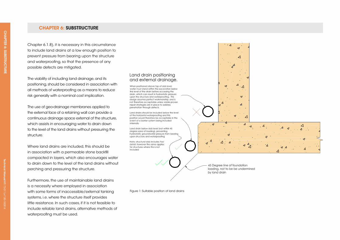
CHAPTER 6: SUBSTRUCTURE CH
APTER 6: SU
BSTRUC
TURE
Tec
hn
ica
l Ma
nua
l V7: TS-011a
-7.00-180814
Chapter 6.1.8), it is necessary in this circumstance
to include land drains at a low enough position to
prevent pressure from bearing upon the structure
and waterproofing, so that the presence of any
possible defects are mitigated.
The viability of including land drainage, and its
positioning, should be considered in association with
all methods of waterproofing as a means to reduce
risk generally with a nominal cost implication.
The use of geo-drainage membranes applied to
the external face of a retaining wall can provide a
continuous drainage space external of the structure,
which assists in encouraging water to drain down
to the level of the land drains without pressuring the
structure.
Where land drains are included, this should be
in association with a permeable stone backfill
compacted in layers, which also encourages water
to drain down to the level of the land drains without
perching and pressuring the structure.
Furthermore, the use of maintainable land drains
is a necessity where employed in association
with some forms of inaccessible/external tanking
systems, i.e. where the structure itself provides
little resistance. In such cases, if it is not feasible to
include reliable land drains, alternative methods of
waterproofing must be used.
Figure 1: Suitable position of land drains
CHAPTER 6: SUBSTRUCTURE CH
APTER 6: SU
BSTRUC
TURE
Tec
hn
ica
l Ma
nua
l V7: TS-011a
-7.00-180814
CHAPTER 6
95
The Warranty Surveyor is to be supplied with design
details where external land drainage is included.
6.1.7 intended use and required standard of environmentusage dictates the required ‘grade’ of environment,
or in other words how ‘dry’ a given basement
space must be in order to be suitable for a given
usage. The Designer must therefore consider
how this will be achieved in a particular site and
structure; BS 8102 provides three definitions of
environmental grades (Grades 1, 2 and 3).
Notably, habitable space is Grade 3, where water
penetration is unacceptable. Appropriately
designed environmental controls, such as vapour
barriers, insulation, heating, ventilation and
dehumidification, must be included to control
vapour introduced via occupation sufficiently,
thereby preventing problems of condensation.
Example usage for Grade 2 includes store rooms,
and again water penetration is not acceptable;
however, heating and ventilation is not necessarily
required, albeit that some degree of ventilation
is recommended even in basic storage space,
which may otherwise suffer condensation-related
dampness.
Grade 1 differs in that some degree of liquid
water penetration is acceptable, i.e. minimal
seepage as long as a space remains fit for
purpose. An example of Grade 1 is basic car
parking. Most basements should be constructed
to allow a minimum of Grade 2, with Grade 3
being necessary for occupied space. Grade 1 is
suitable for basement car parking only (excluding
basement store rooms and access wells), and this
should be agreed on a per scheme basis.
6.1.8 Defects and remedial measuresWithin BS 8102, Designers are advised to consider
the probability that systems may not be installed
perfectly and that defects may occur as a result
of this, or that defects may be present in supplied
materials.
Designing on the assumption that a system will not
be totally perfect or free of defects necessitates
that consideration is given to the feasibility of
repairing those defects, or ensuring that they
are of no consequence, such as where systems
are not accessible for repair. Different structures,
Waterproofing Systems and sites have a bearing
upon this consideration.
Strategies for repair of a given system must be
considered as part of the design process. Further
commentary is provided within each of the specific
system type sections.
The detail of an appropriate repair strategy may be
requested by the Warranty Surveyor in relation to a
given waterproofing design.
6.1.9 forms of waterproofingBS 8102 defines three forms of waterproofing
protection: Type A, barrier protection (commonly
referred to as ‘tanking’), Type B, structurally integral
protection, and Type C, drained protection.
6.1.9.1 Type A, barrier protectionThis form of waterproofing relies on the inclusion of
a physical barrier material applied on or within the
structure, often where the structure itself provides
little resistance to the penetration of water. A variety
of considerations apply:
• Suitability of the substrate, primarily applicable
where tanking products are applied internally,
in that the bond between the product and the
substrate on which it is applied must be
sufficient to resist hydrostatic ground water
pressure.
• The requirement for preparation of substrates to
accept tanking mediums.
• Movement, which in rigid tanking systems may
encourage cracking through which water may
penetrate, where pressure comes to bear.
• Loading, where hydrostatic pressure is applied
to the structure as a result of exclusion via the
tanking medium, i.e. structures must be
designed to resist loads applied to them.
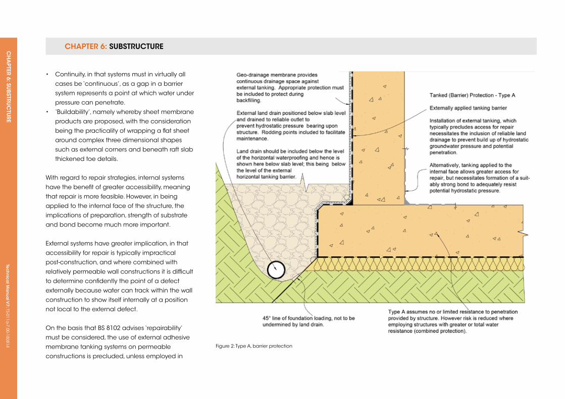
CHAPTER 6: SUBSTRUCTURE CH
APTER 6: SU
BSTRUC
TURE
Tec
hn
ica
l Ma
nua
l V7: TS-011a
-7.00-180814
• Continuity, in that systems must in virtually all
cases be ‘continuous’, as a gap in a barrier
system represents a point at which water under
pressure can penetrate.
• ‘Buildability’, namely whereby sheet membrane
products are proposed, with the consideration
being the practicality of wrapping a flat sheet
around complex three dimensional shapes
such as external corners and beneath raft slab
thickened toe details.
With regard to repair strategies, internal systems
have the benefit of greater accessibility, meaning
that repair is more feasible. However, in being
applied to the internal face of the structure, the
implications of preparation, strength of substrate
and bond become much more important.
External systems have greater implication, in that
accessibility for repair is typically impractical
post-construction, and where combined with
relatively permeable wall constructions it is difficult
to determine confidently the point of a defect
externally because water can track within the wall
construction to show itself internally at a position
not local to the external defect.
On the basis that BS 8102 advises ‘repairability’
must be considered, the use of external adhesive
membrane tanking systems on permeable
constructions is precluded, unless employed in
Figure 2: Type A, barrier protection
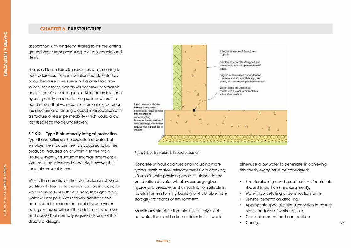
CHAPTER 6: SUBSTRUCTURE CH
APTER 6: SU
BSTRUC
TURE
Tec
hn
ica
l Ma
nua
l V7: TS-011a
-7.00-180814
CHAPTER 6
97
association with long-term strategies for preventing
ground water from pressuring, e.g. serviceable land
drains.
The use of land drains to prevent pressure coming to
bear addresses the consideration that defects may
occur, because if pressure is not allowed to come
to bear then these defects will not allow penetration
and so are of no consequence. Risk can be lessened
by using a ‘fully bonded’ tanking system, where the
bond is such that water cannot track along between
the structure and tanking product, in association with
a structure of lesser permeability which would allow
localised repair to be undertaken.
6.1.9.2 Type B, structurally integral protectionType B also relies on the exclusion of water, but
employs the structure itself as opposed to barrier
products included on or within it. In the main,
Figure 3 -Type B, Structurally Integral Protection; is
formed using reinforced concrete; however, this
may take several forms.
Where the objective is the total exclusion of water,
additional steel reinforcement can be included to
limit cracking to less than 0.2mm, through which
water will not pass. Alternatively, additives can
be included to reduce permeability, with water
being excluded without the addition of steel over
and above that normally required as part of the
structural design.
Figure 3: Type B, structurally integral protection
Concrete without additives and including more
typical levels of steel reinforcement (with cracking
<0.3mm), while providing good resistance to the
penetration of water, will allow seepage given
hydrostatic pressure, and as such is not suitable in
isolation unless forming basic (non-habitable, non-
storage) standards of environment.
As with any structure that aims to entirely block
out water, this must be free of defects that would
otherwise allow water to penetrate. In achieving
this, the following must be considered:
• Structural design and specification of materials
(based in part on site assessment).
• Water stop detailing at construction joints.
• Service penetration detailing.
• Appropriate specialist site supervision to ensure
high standards of workmanship.
• Good placement and compaction.
• Curing.
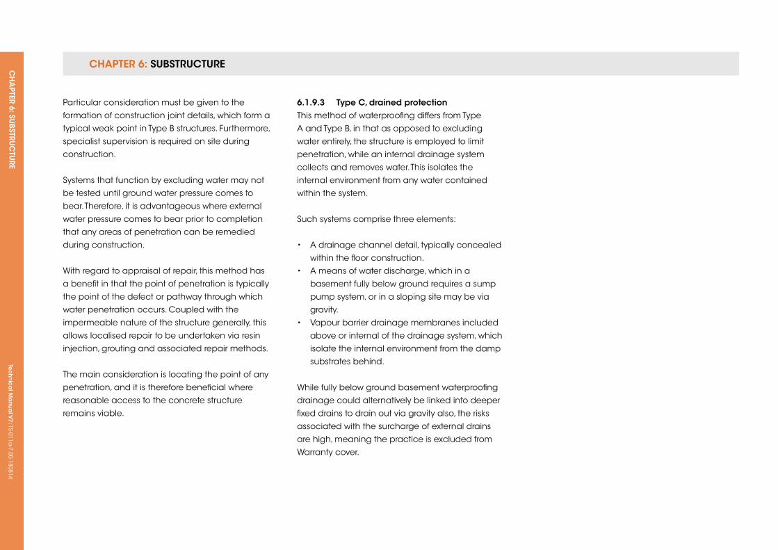
CHAPTER 6: SUBSTRUCTURE CH
APTER 6: SU
BSTRUC
TURE
Tec
hn
ica
l Ma
nua
l V7: TS-011a
-7.00-180814
Particular consideration must be given to the
formation of construction joint details, which form a
typical weak point in Type B structures. Furthermore,
specialist supervision is required on site during
construction.
Systems that function by excluding water may not
be tested until ground water pressure comes to
bear. Therefore, it is advantageous where external
water pressure comes to bear prior to completion
that any areas of penetration can be remedied
during construction.
With regard to appraisal of repair, this method has
a benefit in that the point of penetration is typically
the point of the defect or pathway through which
water penetration occurs. Coupled with the
impermeable nature of the structure generally, this
allows localised repair to be undertaken via resin
injection, grouting and associated repair methods.
The main consideration is locating the point of any
penetration, and it is therefore beneficial where
reasonable access to the concrete structure
remains viable.
6.1.9.3 Type C, drained protectionThis method of waterproofing differs from Type
A and Type B, in that as opposed to excluding
water entirely, the structure is employed to limit
penetration, while an internal drainage system
collects and removes water. This isolates the
internal environment from any water contained
within the system.
Such systems comprise three elements:
• A drainage channel detail, typically concealed
within the floor construction.
• A means of water discharge, which in a
basement fully below ground requires a sump
pump system, or in a sloping site may be via
gravity.
• Vapour barrier drainage membranes included
above or internal of the drainage system, which
isolate the internal environment from the damp
substrates behind.
While fully below ground basement waterproofing
drainage could alternatively be linked into deeper
fixed drains to drain out via gravity also, the risks
associated with the surcharge of external drains
are high, meaning the practice is excluded from
Warranty cover.
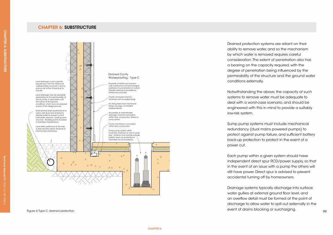
CHAPTER 6: SUBSTRUCTURE CH
APTER 6: SU
BSTRUC
TURE
Tec
hn
ica
l Ma
nua
l V7: TS-011a
-7.00-180814
CHAPTER 6
99Figure 4: Type C, drained protection
Drained protection systems are reliant on their ability to remove water, and so the mechanism by which water is removed requires careful consideration. The extent of penetration also has a bearing on the capacity required, with the degree of penetration being influenced by the permeability of the structure and the ground water conditions externally.
Notwithstanding the above, the capacity of such systems to remove water must be adequate to deal with a worst-case scenario, and should be engineered with this in mind to provide a suitably low-risk system.
Sump pump systems must include mechanical redundancy (dual mains powered pumps) to protect against pump failure, and sufficient battery back-up protection to protect in the event of a power cut.
Each pump within a given system should have independent direct spur RCD/power supply, so that in the event of an issue with a pump the others will still have power. Direct spur is advised to prevent accidental turning off by homeowners.
Drainage systems typically discharge into surface water gullies at external ground floor level, and an overflow detail must be formed at the point of discharge to allow water to spill out externally in the
event of drains blocking or surcharging.
CHAPTER 6: SUBSTRUCTURE CH
APTER 6: SU
BSTRUC
TURE
Tec
hn
ica
l Ma
nua
l V7: TS-011a
-7.00-180814
Systems can drain by gravity to low ground
externally, i.e. where properties are part retaining
and constructed into sloping sites. As with pumped
systems, if connecting to mains drains, an overflow
detail must be employed to allow water to spill
externally in the event of an issue.
Internal drained protection systems must include
drainage channels local to the external wall floor
junctions, which facilitates maintenance and
allows systems to function and protect in the long
term. Where larger footprints are involved, cross
floor channels must be included, ideally local to
construction joints where the structure is more
vulnerable to ground water penetration.
Systems must be maintained annually as a
minimum. The detail of this requirement must be
included in the documentation provided to the
homeowner.
Water moving over and through new concrete
leaches free lime within the early life of the
structure, and suitable treatments should be
applied to concrete to minimise this.
Substrates should be clean and free of loose
or friable materials prior to the application of
membrane linings.
Flood testing of a system should be undertaken
during construction to check efficacy and that
water flows freely to the discharge point. Testing
in this manner to prove that a system functions
as intended is a key benefit of this method of
waterproofing, and must be part of the process.
Systems creating a habitable space require the
inclusion of vapour barrier drainage membranes
within the wall and floor construction.
Where elements of the drained protection system
are included within cavities, cavities must be kept
clear of mortar snots and debris.
Continuity of the structure must be considered
because the resistance to water provided by a
given structure is reduced by apertures through
which water can freely move. Examples could
include holes present within existing buildings, or
in new construction where land drains are linked
to sump pump systems, with the sumps being
installed internal of the retaining shell, e.g. in light
wells, thus providing a pathway for water to enter.
Temporary 110v pumps should be included during
construction to address water penetration as
necessary; 240v systems should be installed and
commissioned as soon as viable once the 240v
supply is installed.
Systems must not link directly by gravity to
soakaways where any of the previously stated
scenarios occur because of the danger
of backflow of water through the pipes or
waterlogging of the local ground above slab/
DPM level. However, where such conditions are not
present, sump pump systems may be employed to
lift water up to ground level externally, discharging
into gullies linked to soakaways. This detail should
be designed by the Waterproofing Specialist.
In consideration of the repair of defects, the
inclusion of drained protection systems internally
generally ensures that systems can be accessed
for localised repair; however, this may be lessened
where systems are sandwiched within the structure,
i.e. within cavities.
Part of the underlying rationale of drained
protection is that water is removed continuously, so
that it does not collect and place pressure upon
membrane linings installed over the drainage.
If water does not place pressure upon such
membranes, then the incidence of any defects
within them is generally of no consequence, and
so maintaining the efficacy of the drainage in the
long term ensures that such defects are negated.
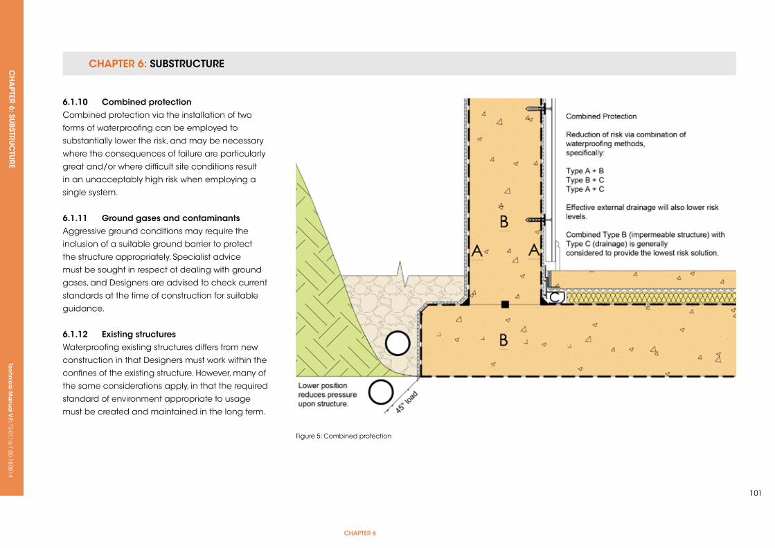
CHAPTER 6: SUBSTRUCTURE CH
APTER 6: SU
BSTRUC
TURE
Tec
hn
ica
l Ma
nua
l V7: TS-011a
-7.00-180814
CHAPTER 6
101
6.1.10 Combined protectionCombined protection via the installation of two
forms of waterproofing can be employed to
substantially lower the risk, and may be necessary
where the consequences of failure are particularly
great and/or where difficult site conditions result
in an unacceptably high risk when employing a
single system.
6.1.11 ground gases and contaminantsAggressive ground conditions may require the
inclusion of a suitable ground barrier to protect
the structure appropriately. Specialist advice
must be sought in respect of dealing with ground
gases, and Designers are advised to check current
standards at the time of construction for suitable
guidance.
6.1.12 existing structuresWaterproofing existing structures differs from new
construction in that Designers must work within the
confines of the existing structure. However, many of
the same considerations apply, in that the required
standard of environment appropriate to usage
must be created and maintained in the long term.
Figure 5: Combined protection

Tec
hn
ica
l Ma
nua
l V6: TS-011a
-6.00-010413Te
ch
nic
al M
anu
al V
7: TS-011a-7.00-180814
FUNCTIONAL REQUIREMENTS
6.2 WALLs BeLoW grounD
Workmanshipi. All workmanship must be within the tolerances defined in Chapter 1
of this Manual.
ii. All work is to be carried out by a technically competent person in
a workmanlike manner.
Materialsi. All materials should be stored correctly in a manner that will not cause
damage or deterioration of the product.
ii. All materials, products and building systems shall be appropriate and
suitable for their intended purpose.
iii. The structure shall, unless specifically agreed otherwise with the
Warranty provider, have a life of not less than 60 years. Individual
components and assemblies, not integral to the structure, may have
a lesser durability, but not in any circumstances less than 15 years.
Designi. The design and specifications shall provide a clear indication of the
design intent and demonstrate a satisfactory level of performance.
ii. Structural elements outside the parameters of regional Approved
Documents must be supported by structural calculations provided by
a suitably qualified expert.
iii. The design and construction must meet the relevant Building
Regulations, British Standards, Eurocodes and other statutory
requirements.

CHAPTER 6: SUBSTRUCTURE CH
APTER 6: SU
BSTRUC
TURE
Tec
hn
ica
l Ma
nua
l V7: TS-011a
-7.00-180814
CHAPTER 6
103
6.2.1 Bricks and blocks below groundThe selected bricks should be appropriately
durable against saturation in accordance with
BS 3921; the brick and block classifications suitable
for walls up to Damp Proof Course (DPC) are
shown in Table 1.
If there are sulphates in the ground and/or there
is ground water present, confirmation by the
manufacturer that the brick or block is suitable for
use below ground should be provided.
6.2.2 Mortar mixesMortars below DPC are exposed to higher
saturation and therefore require a higher durability,
as indicated in Table 2.
Brick / block type use / minimum standard of brick or block
Walls up to DPC Walls up to DPC (sulphates in soils)
Clay bricks FL,FN,ML,MN (a) FL,FN,ML,MN (a)
Calcium silicate bricks Class 3 (b) Class 3 (b)
Concrete bricks Min strength 20N/mm2 (c) Min strength 20N/mm2 (c)
Block work Min strength 7N/mm2 and density greater than 1500kg/m3 (d)
Min strength 7N/mm2 and density greater than 1500kg/m3 (d)
notes:
(a) If the site is wet or saturated at ground level use FL or FN bricks only.(b) Denotes a minimum standard - higher classifications may be used.(c) For Class 1 and Class 2 sulphates, check with manufacturers to confirm suitability of brick; for Class 3 sulphates, use engineering quality concrete bricks.(d) Autoclaved aerated blocks with independent appropriate third party certification are acceptable.
Table 1: Suitability of bricks and blocks below ground
Proportion by volume
High durability mortar for a use below or near external ground level
Classification(Bs en 998-2)
Portland cement:lime: sand
Air-entrained Portland cement:
sand
Masonry cement: sand strength
(ii) (a) 1:0.5:4-4.5 (b) 1:3-4 (b) 1:2.5-3.5 (b) 5.0N/mm2
Notes:
(a) For concrete or calcium silicate brick use a designation (iii) mortar. (b) Where soil or ground water sulphate levels are appreciable (Class 3 or higher) use sulphate resisting Portland Cement.
Table 2: Typical mortar mixes for below ground masonry
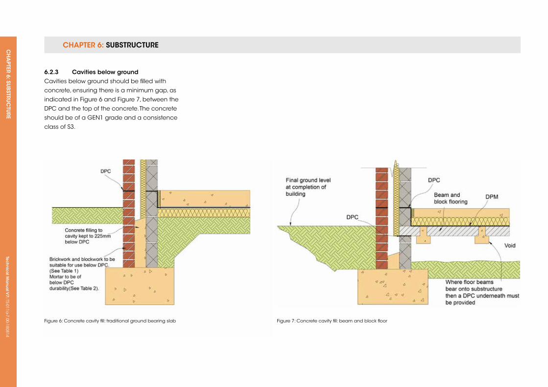
CHAPTER 6: SUBSTRUCTURE CH
APTER 6: SU
BSTRUC
TURE
Tec
hn
ica
l Ma
nua
l V7: TS-011a
-7.00-180814
6.2.3 Cavities below groundCavities below ground should be filled with
concrete, ensuring there is a minimum gap, as
indicated in Figure 6 and Figure 7, between the
DPC and the top of the concrete. The concrete
should be of a GEN1 grade and a consistence
class of S3.
Figure 6: Concrete cavity fill: traditional ground bearing slab Figure 7: Concrete cavity fill: beam and block floor
Tec
hn
ica
l Ma
nua
l V6: TS-011a
-6.00-010413Te
ch
nic
al M
anu
al V
7: TS-011a-7.00-180814
FUNCTIONAL REQUIREMENTS
105
6.3 DAMP Proofing
Workmanshipi. All workmanship must be within the tolerances defined in Chapter 1
of this Manual.
ii. All work is to be carried out by a technically competent person in a
workmanlike manner.
iii. Certification is required for any work completed by an approved
installer.
Materialsi. All materials should be stored correctly in a manner that will not cause
damage or deterioration of the product.
ii. All materials, products and building systems shall be appropriate and
suitable for their intended purpose.
iii. The structure shall, unless specifically agreed otherwise with the
Warranty provider, have a life of not less than 60 years. Individual
components and assemblies, not integral to the structure, may have a
lesser durability, but not in any circumstances less than 15 years.
Designi. The design and specifications shall provide a clear indication of the
design intent and demonstrate a satisfactory level of performance.
ii. Damp proofing works should prevent any external moisture passing
into the internal environment of the dwelling.
iii. Structural elements outside the parameters of regional Approved
Documents must be supported by structural calculations provided by
a suitably qualified expert.
iv. The design and construction must meet the relevant Building
Regulations, British Standards, Eurocodes and other statutory
requirements.
CHAPTer 6
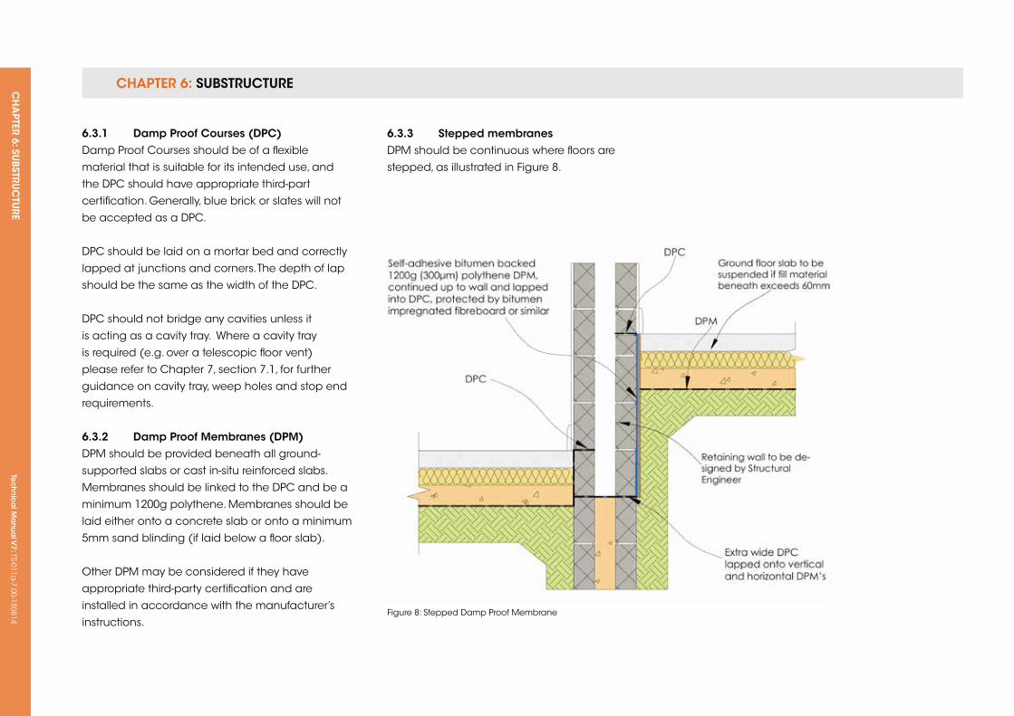
CHAPTER 6: SUBSTRUCTURE CH
APTER 6: SU
BSTRUC
TURE
Tec
hn
ica
l Ma
nua
l V7: TS-011a
-7.00-180814
6.3.1 Damp Proof Courses (DPC)Damp Proof Courses should be of a flexible
material that is suitable for its intended use, and
the DPC should have appropriate third-part
certification. Generally, blue brick or slates will not
be accepted as a DPC.
DPC should be laid on a mortar bed and correctly
lapped at junctions and corners. The depth of lap
should be the same as the width of the DPC.
DPC should not bridge any cavities unless it
is acting as a cavity tray. Where a cavity tray
is required (e.g. over a telescopic floor vent)
please refer to Chapter 7, section 7.1, for further
guidance on cavity tray, weep holes and stop end
requirements.
6.3.2 Damp Proof Membranes (DPM)DPM should be provided beneath all ground-
supported slabs or cast in-situ reinforced slabs.
Membranes should be linked to the DPC and be a
minimum 1200g polythene. Membranes should be
laid either onto a concrete slab or onto a minimum
5mm sand blinding (if laid below a floor slab).
Other DPM may be considered if they have
appropriate third-party certification and are
installed in accordance with the manufacturer’s
instructions.
6.3.3 stepped membranesDPM should be continuous where floors are
stepped, as illustrated in Figure 8.
Figure 8: Stepped Damp Proof Membrane

Tec
hn
ica
l Ma
nua
l V6: TS-011a
-6.00-010413Te
ch
nic
al M
anu
al V
7: TS-011a-7.00-180814
FUNCTIONAL REQUIREMENTS
107
6.4 grounD fLoors
Workmanshipi. All workmanship must be within the tolerances defined in Chapter 1
of this Manual.
ii. All work is to be carried out by a technically competent person in
a workmanlike manner.
Materialsi. All materials should be stored correctly in a manner that will not cause
damage or deterioration of the product.
ii. All materials, products and building systems shall be appropriate and
suitable for their intended purpose.
iii. The structure shall, unless specifically agreed otherwise with the
Warranty provider, have a life of not less than 60 years. Individual
components and assemblies, not integral to the structure, may have
a lesser durability, but not in any circumstances less than 15 years.
Designi. The design and specifications shall provide a clear indication of the
design intent and demonstrate a satisfactory level of performance.
ii. Structural elements outside the parameters of regional Approved
Documents must be supported by structural calculations provided by
a suitably qualified expert.
iii. The design and construction must meet the relevant Building
Regulations, British Standards, Eurocodes and other statutory
requirements.
iv. Precast structural elements must have structural calculations that
prove their adequacy endorsed by the manufacturer.
CHAPTer 6

CHAPTER 6: SUBSTRUCTURE CH
APTER 6: SU
BSTRUC
TURE
Tec
hn
ica
l Ma
nua
l V7: TS-011a
-7.00-180814
6.4.1 ground supported concrete floors
6.4.1.1 site preparationThe site beneath the floor should be stripped of all
topsoil, organic matter or tree roots prior to filling
and compaction.
Suitable hard core would include inert quarried
material such as limestone or granite. Recycled
aggregates may be used, which include crushed
concrete or broken brick; however, these must be
completely free of contaminants and plaster and
should be delivered to site from a supplier that has
a quality audit process in place.
Materials available as a result of any site
demolition should not be used as hard core
beneath floor slabs unless specifically agreed by
the Warranty Surveyor, and only then if it can be
demonstrated that the material is completely free
of contaminants and plaster.
Hard core should be placed and compacted in
150mm nominal layers and be fully consolidated
using a mechanical compactor. A ground
supported concrete floor will not be acceptable
where the depth of hard core required exceeds
600mm, and an alternative ground floor solution,
e.g. beam and block, should be considered.
Hard core material should not be saturated, and
caution should be taken to ensure that new walls
are not disturbed by compaction of the hard core.
6.4.1.2 Damp Proof Membranes (DPM)DPM can be laid either above or below the floor
slab depending on the finish of the floor. The
membrane should be lapped into the DPC by at
least 100mm.
Figure 9: Typical ground bearing floor slab
6.4.1.3 insulationInsulation that is to be provided to ground floor
can be placed either above or below the concrete
slab. Insulation should be installed in accordance
with the manufacturer’s instructions and be
durable enough to withstand floor loadings and
moisture. A number of insulation products require
an additional DPM to protect the surface of the
insulation. It is important that this additional
membrane is incorporated, which is shown in
Figure 9.
6.4.1.4 Concreting of floorsPrior to concreting, any water or debris that may
have collected on top of the DPM should be
removed. Concrete should ideally be ready mixed
and be of at least GEN3. Expansion joints should
be provided in accordance with Chapter 2.2 of this
Manual.
6.4.2 suspended reinforced in-situ slabs
6.4.2.1 structural designA cast in-situ suspended concrete slab should
be designed by a qualified Structural Engineer.
The structural design should include the following
information:
• Adequacy of walls that support the concrete
slab (intermediate and perimeter walls).
• Suitable thickness, correct durability of concrete
and correct provision of reinforcing.
• Provision of anti-crack reinforcing to the
perimeter of floors.
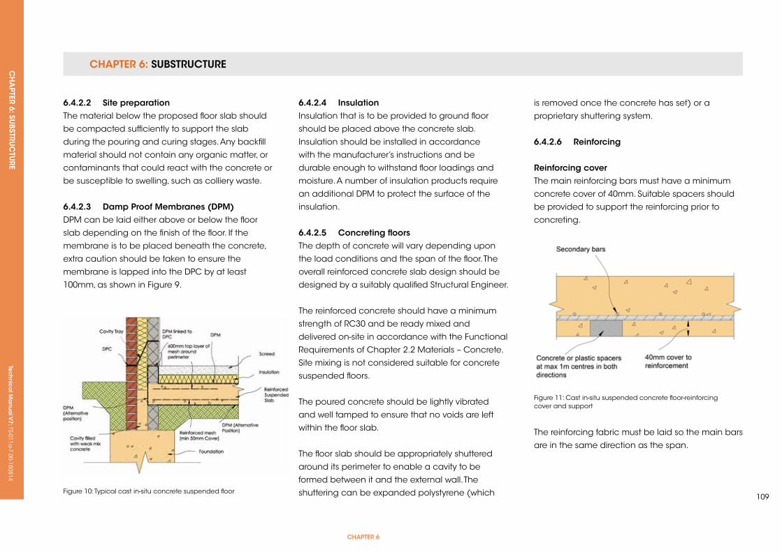
CHAPTER 6: SUBSTRUCTURE CH
APTER 6: SU
BSTRUC
TURE
Tec
hn
ica
l Ma
nua
l V7: TS-011a
-7.00-180814
CHAPTER 6
109
6.4.2.2 site preparationThe material below the proposed floor slab should
be compacted sufficiently to support the slab
during the pouring and curing stages. Any backfill
material should not contain any organic matter, or
contaminants that could react with the concrete or
be susceptible to swelling, such as colliery waste.
6.4.2.3 Damp Proof Membranes (DPM)DPM can be laid either above or below the floor
slab depending on the finish of the floor. If the
membrane is to be placed beneath the concrete,
extra caution should be taken to ensure the
membrane is lapped into the DPC by at least
100mm, as shown in Figure 9.
Figure 10: Typical cast in-situ concrete suspended floor
Figure 11: Cast in-situ suspended concrete floor-reinforcing cover and support
6.4.2.4 insulationInsulation that is to be provided to ground floor
should be placed above the concrete slab.
Insulation should be installed in accordance
with the manufacturer’s instructions and be
durable enough to withstand floor loadings and
moisture. A number of insulation products require
an additional DPM to protect the surface of the
insulation.
6.4.2.5 Concreting floorsThe depth of concrete will vary depending upon
the load conditions and the span of the floor. The
overall reinforced concrete slab design should be
designed by a suitably qualified Structural Engineer.
The reinforced concrete should have a minimum
strength of RC30 and be ready mixed and
delivered on-site in accordance with the Functional
Requirements of Chapter 2.2 Materials – Concrete.
Site mixing is not considered suitable for concrete
suspended floors.
The poured concrete should be lightly vibrated
and well tamped to ensure that no voids are left
within the floor slab.
The floor slab should be appropriately shuttered
around its perimeter to enable a cavity to be
formed between it and the external wall. The
shuttering can be expanded polystyrene (which
is removed once the concrete has set) or a
proprietary shuttering system.
6.4.2.6 reinforcing
reinforcing coverThe main reinforcing bars must have a minimum
concrete cover of 40mm. Suitable spacers should
be provided to support the reinforcing prior to
concreting.
The reinforcing fabric must be laid so the main bars
are in the same direction as the span.
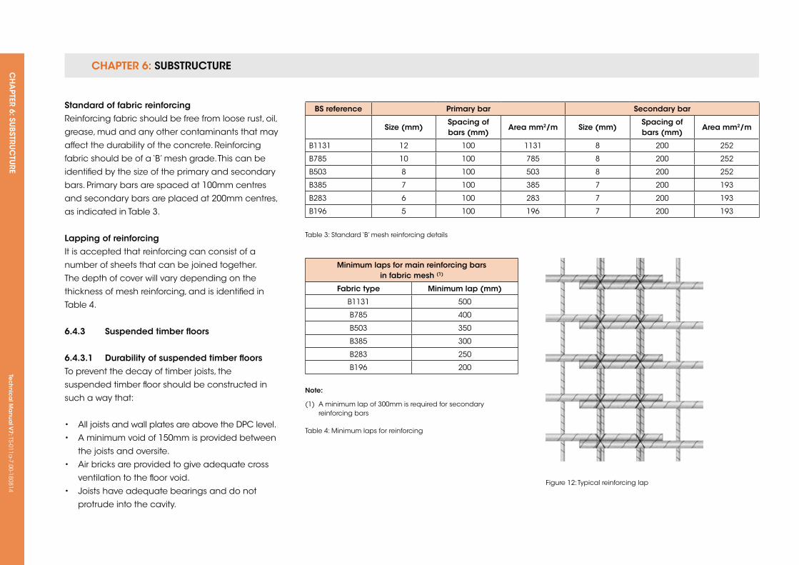
CHAPTER 6: SUBSTRUCTURE CH
APTER 6: SU
BSTRUC
TURE
Tec
hn
ica
l Ma
nua
l V7: TS-011a
-7.00-180814
standard of fabric reinforcingReinforcing fabric should be free from loose rust, oil,
grease, mud and any other contaminants that may
affect the durability of the concrete. Reinforcing
fabric should be of a ‘B’ mesh grade. This can be
identified by the size of the primary and secondary
bars. Primary bars are spaced at 100mm centres
and secondary bars are placed at 200mm centres,
as indicated in Table 3.
Lapping of reinforcing It is accepted that reinforcing can consist of a
number of sheets that can be joined together.
The depth of cover will vary depending on the
thickness of mesh reinforcing, and is identified in
Table 4.
6.4.3 suspended timber floors
6.4.3.1 Durability of suspended timber floorsTo prevent the decay of timber joists, the
suspended timber floor should be constructed in
such a way that:
• All joists and wall plates are above the DPC level.
• A minimum void of 150mm is provided between
the joists and oversite.
• Air bricks are provided to give adequate cross
ventilation to the floor void.
• Joists have adequate bearings and do not
protrude into the cavity.
Bs reference Primary bar secondary bar
size (mm)spacing of bars (mm)
Area mm2/m size (mm)spacing of bars (mm)
Area mm2/m
B1131 12 100 1131 8 200 252
B785 10 100 785 8 200 252
B503 8 100 503 8 200 252
B385 7 100 385 7 200 193
B283 6 100 283 7 200 193
B196 5 100 196 7 200 193
Minimum laps for main reinforcing bars in fabric mesh (1)
fabric type Minimum lap (mm)
B1131 500
B785 400
B503 350
B385 300
B283 250
B196 200
note:
(1) A minimum lap of 300mm is required for secondary reinforcing bars
Table 4: Minimum laps for reinforcing
Table 3: Standard ‘B’ mesh reinforcing details
Figure 12: Typical reinforcing lap
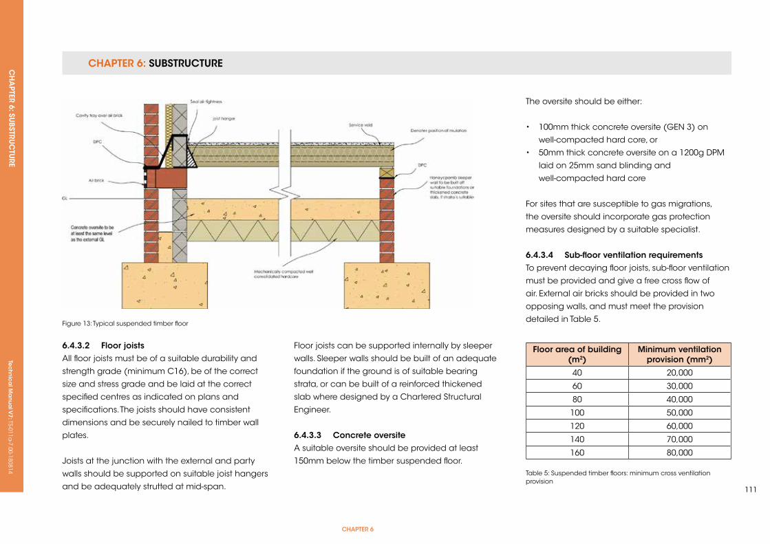
CHAPTER 6: SUBSTRUCTURE CH
APTER 6: SU
BSTRUC
TURE
Tec
hn
ica
l Ma
nua
l V7: TS-011a
-7.00-180814
CHAPTER 6
111
6.4.3.2 floor joistsAll floor joists must be of a suitable durability and
strength grade (minimum C16), be of the correct
size and stress grade and be laid at the correct
specified centres as indicated on plans and
specifications. The joists should have consistent
dimensions and be securely nailed to timber wall
plates.
Joists at the junction with the external and party
walls should be supported on suitable joist hangers
and be adequately strutted at mid-span.
Figure 13: Typical suspended timber floor
Floor joists can be supported internally by sleeper
walls. Sleeper walls should be built of an adequate
foundation if the ground is of suitable bearing
strata, or can be built of a reinforced thickened
slab where designed by a Chartered Structural
Engineer.
6.4.3.3 Concrete oversiteA suitable oversite should be provided at least
150mm below the timber suspended floor.
The oversite should be either:
• 100mm thick concrete oversite (GEN 3) on
well-compacted hard core, or
• 50mm thick concrete oversite on a 1200g DPM
laid on 25mm sand blinding and
well-compacted hard core
For sites that are susceptible to gas migrations,
the oversite should incorporate gas protection
measures designed by a suitable specialist.
6.4.3.4 sub-floor ventilation requirementsTo prevent decaying floor joists, sub-floor ventilation
must be provided and give a free cross flow of
air. External air bricks should be provided in two
opposing walls, and must meet the provision
detailed in Table 5.
Table 5: Suspended timber floors: minimum cross ventilation provision
floor area of building (m2)
Minimum ventilation provision (mm2)
40 20,000
60 30,000
80 40,000
100 50,000
120 60,000
140 70,000
160 80,000
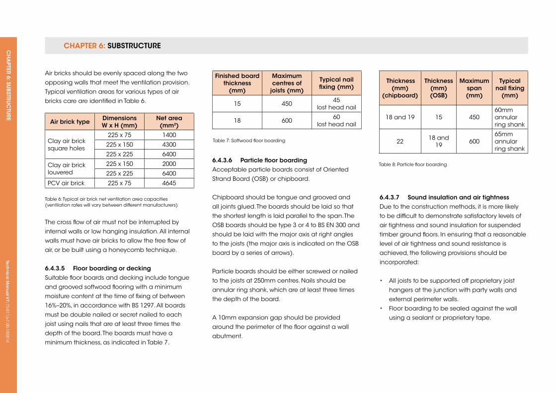
CHAPTER 6: SUBSTRUCTURE CH
APTER 6: SU
BSTRUC
TURE
Tec
hn
ica
l Ma
nua
l V7: TS-011a
-7.00-180814
The cross flow of air must not be interrupted by
internal walls or low hanging insulation. All internal
walls must have air bricks to allow the free flow of
air, or be built using a honeycomb technique.
6.4.3.5 floor boarding or deckingSuitable floor boards and decking include tongue
and grooved softwood flooring with a minimum
moisture content at the time of fixing of between
16%–20%, in accordance with BS 1297. All boards
must be double nailed or secret nailed to each
joist using nails that are at least three times the
depth of the board. The boards must have a
minimum thickness, as indicated in Table 7.
Table 6: Typical air brick net ventilation area capacities (ventilation rates will vary between different manufacturers)
Table 7: Softwood floor boarding
Air brick type Dimensions W x H (mm)
net area (mm2)
Clay air brick square holes
225 x 75 1400
225 x 150 4300
225 x 225 6400
Clay air brick louvered
225 x 150 2000
225 x 225 6400
PCV air brick 225 x 75 4645
6.4.3.6 Particle floor boarding Acceptable particle boards consist of Oriented
Strand Board (OSB) or chipboard.
Chipboard should be tongue and grooved and
all joints glued. The boards should be laid so that
the shortest length is laid parallel to the span. The
OSB boards should be type 3 or 4 to BS EN 300 and
should be laid with the major axis at right angles
to the joists (the major axis is indicated on the OSB
board by a series of arrows).
Particle boards should be either screwed or nailed
to the joists at 250mm centres. Nails should be
annular ring shank, which are at least three times
the depth of the board.
A 10mm expansion gap should be provided
around the perimeter of the floor against a wall
abutment.
finished board thickness
(mm)
Maximum centres of
joists (mm)
Typical nail fixing (mm)
15 450 45 lost head nail
18 600 60 lost head nail
Thickness (mm)
(chipboard)
Thickness (mm) (osB)
Maximum span (mm)
Typical nail fixing
(mm)
18 and 19 15 45060mm annular ring shank
22 18 and19 600
65mm annular ring shank
Table 8: Particle floor boarding
6.4.3.7 sound insulation and air tightnessDue to the construction methods, it is more likely
to be difficult to demonstrate satisfactory levels of
air tightness and sound insulation for suspended
timber ground floors. In ensuring that a reasonable
level of air tightness and sound resistance is
achieved, the following provisions should be
incorporated:
• All joists to be supported off proprietary joist
hangers at the junction with party walls and
external perimeter walls.
• Floor boarding to be sealed against the wall
using a sealant or proprietary tape.
Air bricks should be evenly spaced along the two
opposing walls that meet the ventilation provision.
Typical ventilation areas for various types of air
bricks care are identified in Table 6.
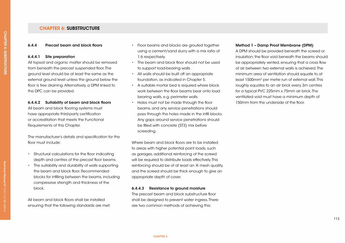
CHAPTER 6: SUBSTRUCTURE CH
APTER 6: SU
BSTRUC
TURE
Tec
hn
ica
l Ma
nua
l V7: TS-011a
-7.00-180814
CHAPTER 6
113
6.4.4 Precast beam and block floors
6.4.4.1 site preparationAll topsoil and organic matter should be removed
from beneath the precast suspended floor. The
ground level should be at least the same as the
external ground level unless the ground below the
floor is free draining. Alternatively, a DPM linked to
the DPC can be provided.
6.4.4.2 suitability of beam and block floorsAll beam and block flooring systems must
have appropriate third-party certification
or accreditation that meets the Functional
Requirements of this Chapter.
The manufacturer’s details and specification for the
floor must include:
• Structural calculations for the floor indicating
depth and centres of the precast floor beams.
• The suitability and durability of walls supporting
the beam and block floor. Recommended
blocks for infilling between the beams, including
compressive strength and thickness of the
block.
All beam and block floors shall be installed
ensuring that the following standards are met:
• Floor beams and blocks are grouted together
using a cement/sand slurry with a mix ratio of
1:6 respectively.
• The beam and block floor should not be used
to support load-bearing walls .
• All walls should be built off an appropriate
foundation, as indicated in Chapter 5.
• A suitable mortar bed is required where block
work between the floor beams bear onto load
bearing walls, e.g. perimeter walls.
• Holes must not be made through the floor
beams, and any service penetrations should
pass through the holes made in the infill blocks.
Any gaps around service penetrations should
be filled with concrete (ST3) mix before
screeding.
Where beam and block floors are to be installed
to areas with higher potential point loads, such
as garages, additional reinforcing of the screed
will be required to distribute loads effectively. This
reinforcing should be of at least an ‘A’ mesh quality,
and the screed should be thick enough to give an
appropriate depth of cover.
6.4.4.3 resistance to ground moistureThe precast beam and block substructure floor
shall be designed to prevent water ingress. There
are two common methods of achieving this:
Method 1 – Damp Proof Membrane (DPM)A DPM should be provided beneath the screed or
insulation; the floor void beneath the beams should
be appropriately vented, ensuring that a cross flow
of air between two external walls is achieved. The
minimum area of ventilation should equate to at
least 1500mm2 per metre run of external wall. This
roughly equates to an air brick every 3m centres
for a typical PVC 225mm x 75mm air brick. The
ventilated void must have a minimum depth of
150mm from the underside of the floor.
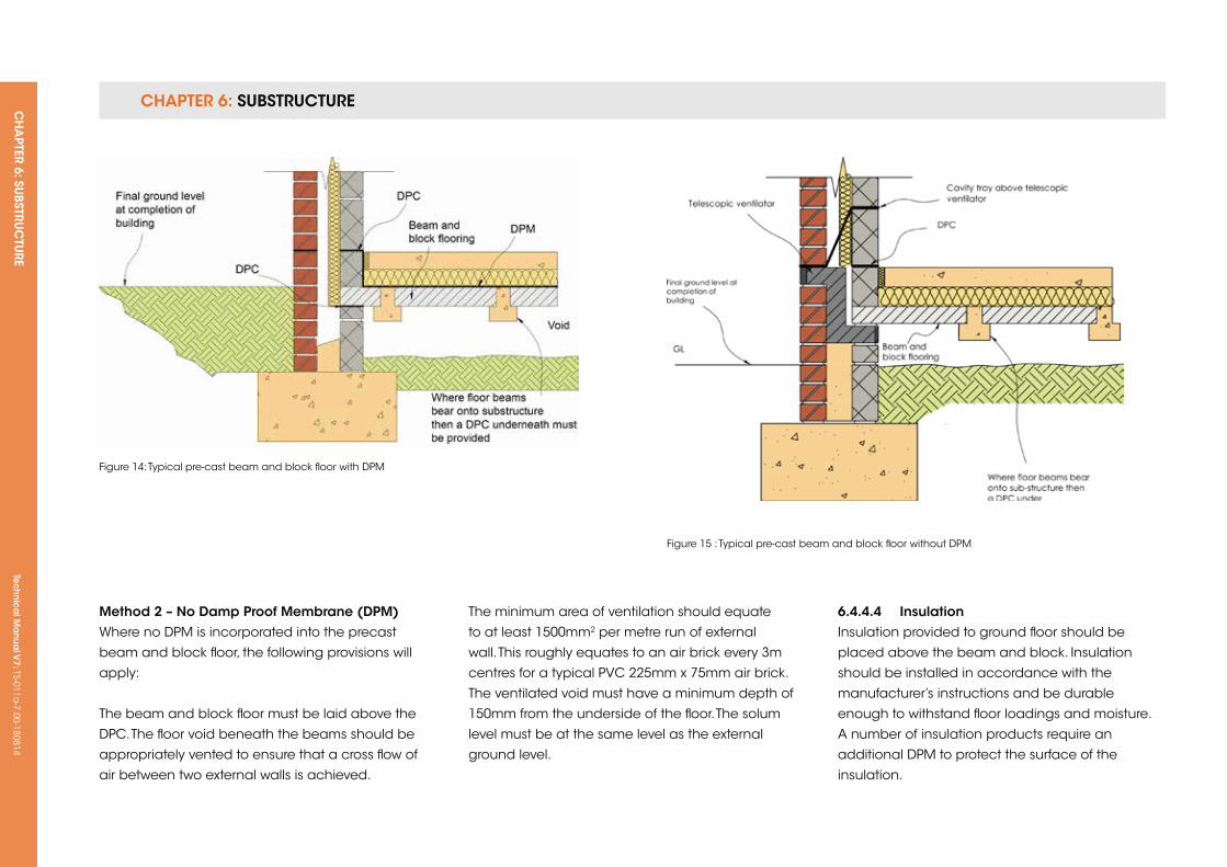
CHAPTER 6: SUBSTRUCTURE CH
APTER 6: SU
BSTRUC
TURE
Tec
hn
ica
l Ma
nua
l V7: TS-011a
-7.00-180814
Method 2 – no Damp Proof Membrane (DPM)Where no DPM is incorporated into the precast
beam and block floor, the following provisions will
apply:
The beam and block floor must be laid above the
DPC. The floor void beneath the beams should be
appropriately vented to ensure that a cross flow of
air between two external walls is achieved.
Figure 14: Typical pre-cast beam and block floor with DPM
Figure 15 : Typical pre-cast beam and block floor without DPM
The minimum area of ventilation should equate
to at least 1500mm2 per metre run of external
wall. This roughly equates to an air brick every 3m
centres for a typical PVC 225mm x 75mm air brick.
The ventilated void must have a minimum depth of
150mm from the underside of the floor. The solum
level must be at the same level as the external
ground level.
6.4.4.4 insulationInsulation provided to ground floor should be
placed above the beam and block. Insulation
should be installed in accordance with the
manufacturer’s instructions and be durable
enough to withstand floor loadings and moisture.
A number of insulation products require an
additional DPM to protect the surface of the
insulation.
CH
APTER 7: Su
PERSTRuC
TuRE
Tec
hn
ica
l Ma
nua
l V7: TS-011a
-7.00-180814
CHAPTER 7
115
CHAPTer 7: suPersTruCTure
ConTenTs
7.1 ExTERNAL MASONRy WALLS
7.2 STEEL FRAME
7.3 TIMBER FRAME
7.4 WINDOWS AND DOORS
7.5 CHIMNEyS
7.6 BALCONIES
7.7 CLADDING
7.8 ROOF STRuCTuRE
7.9 ROOF COVERING – TRADITIONAL SLATE AND TILES
7.10 ROOF COVERING – CONTINuOuS MEMBRANE ROOFING
7.11 ROOF COVERING – GREEN ROOFING
7.12 ROOF COVERING – METAL DECk ROOFING
Tec
hn
ica
l Ma
nua
l V6: TS-011a
-6.00-010413Te
ch
nic
al M
anu
al V
7: TS-011a-7.00-180814
FUNCTIONAL REQUIREMENTS
Workmanshipi. All workmanship must be within the tolerances defined in Chapter 1
of this Manual.
ii. All work is to be carried out by a technically competent person in
a workmanlike manner.
iii. Cavities should be clear from mortar droppings to prevent moisture
ingress.
iv. Masonry walls should not be laid in extreme weather conditions.
Materialsi. All materials should be stored correctly in a manner that will not cause
damage or deterioration of the product.
ii. All materials, products and building systems shall be appropriate and
suitable for their intended purpose.
iii. Materials should be suitable for the relative exposure of the building in
accordance with the relevant British Standard.
iv. The structure shall, unless specifically agreed otherwise with the
Warranty provider, have a life of not less than 60 years. Individual
components and assemblies, not integral to the structure, may have
a lesser durability, but not in any circumstances less than 15 years.
7.1 exTernAL MAsonry WALLs
Designi. The design and specifications shall provide a clear indication of the
design intent and demonstrate a satisfactory level of performance.
ii. Structural elements outside the parameters of regional Approved
Documents must be supported by structural calculations provided by
a suitably qualified expert.
iii. The design and construction of masonry walls must meet the relevant
Building Regulations, British Standards, Eurocodes and other statutory
requirements.
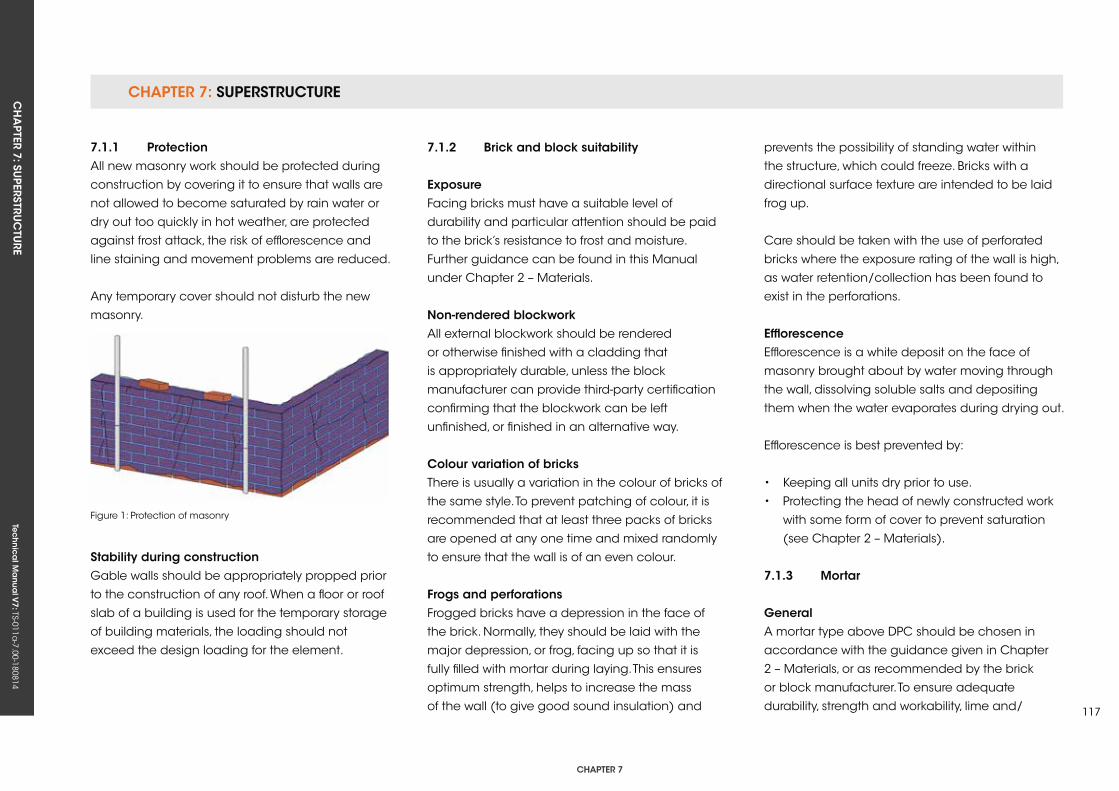
CHAPTER 7: SuPERSTRuCTuRECH
APTER 7: Su
PERSTRuC
TuRE
Tec
hn
ica
l Ma
nua
l V7: TS-011a
-7.00-180814
CHAPTER 7
117
7.1.1 ProtectionAll new masonry work should be protected during
construction by covering it to ensure that walls are
not allowed to become saturated by rain water or
dry out too quickly in hot weather, are protected
against frost attack, the risk of efflorescence and
line staining and movement problems are reduced.
Any temporary cover should not disturb the new
masonry.
stability during constructionGable walls should be appropriately propped prior
to the construction of any roof. When a floor or roof
slab of a building is used for the temporary storage
of building materials, the loading should not
exceed the design loading for the element.
7.1.2 Brick and block suitability
exposureFacing bricks must have a suitable level of
durability and particular attention should be paid
to the brick’s resistance to frost and moisture.
Further guidance can be found in this Manual
under Chapter 2 – Materials.
non-rendered blockworkAll external blockwork should be rendered
or otherwise finished with a cladding that
is appropriately durable, unless the block
manufacturer can provide third-party certification
confirming that the blockwork can be left
unfinished, or finished in an alternative way.
Colour variation of bricksThere is usually a variation in the colour of bricks of
the same style. To prevent patching of colour, it is
recommended that at least three packs of bricks
are opened at any one time and mixed randomly
to ensure that the wall is of an even colour.
frogs and perforationsFrogged bricks have a depression in the face of
the brick. Normally, they should be laid with the
major depression, or frog, facing up so that it is
fully filled with mortar during laying. This ensures
optimum strength, helps to increase the mass
of the wall (to give good sound insulation) and
Figure 1: Protection of masonry
prevents the possibility of standing water within
the structure, which could freeze. Bricks with a
directional surface texture are intended to be laid
frog up.
Care should be taken with the use of perforated
bricks where the exposure rating of the wall is high,
as water retention/collection has been found to
exist in the perforations.
efflorescenceEfflorescence is a white deposit on the face of
masonry brought about by water moving through
the wall, dissolving soluble salts and depositing
them when the water evaporates during drying out.
Efflorescence is best prevented by:
• keeping all units dry prior to use.
• Protecting the head of newly constructed work
with some form of cover to prevent saturation
(see Chapter 2 – Materials).
7.1.3 Mortar
generalA mortar type above DPC should be chosen in
accordance with the guidance given in Chapter
2 – Materials, or as recommended by the brick
or block manufacturer. To ensure adequate
durability, strength and workability, lime and/
CHAPTER 7: SuPERSTRuCTuRE CH
APTER 7: Su
PERSTRuC
TuRE
Tec
hn
ica
l Ma
nua
l V7: TS-011a
-7.00-180814
or air entraining plasticisers may be added to
cement in accordance with the manufacturer’s
recommendations. Cement and sand alone
should not be used unless a strong mix is
specifically required by the design.
Batchingkeep batching and mixing equipment clean to
avoid contamination with materials used previously.
Mortar should be mixed by machine, or use ready
mixed retarded mortars.
MixingMortar should be carefully and consistently
proportioned, and then thoroughly mixed using a
mechanical mixer, except for very small quantities.
7.1.4 Adverse weather
Working in adverse weatherPrecautions should be taken when necessary to
maintain the temperature of bricks, blocks and
mortar above 3°C. The use of anti-freeze as a frost
resistant additive in mortar is not permitted. Further
guidance can be found in Chapter 2 – Materials.
During prolonged periods of hot weather, when
masonry units can become very dry, absorbent
clay bricks may be wetted to reduce suction. Low
absorption bricks, i.e. engineering bricks, should
not be wetted. For calcium silicate and concrete
units, the mortar specification may need to be
changed in order to incorporate an admixture to
assist with water retention. On no account should
masonry units or completed work be saturated with
water.
Dealing with areas of high exposure to frost and wind-driven rain
frost attackFrost-resistant bricks should be used in areas that
are prone to prolonged periods of frost.
If there are any doubts about the suitability of
facing bricks in areas of severe frost exposure,
written clarification by the brick manufacturer
confirming the suitability of the brick should be
provided.
Wind-driven rainTo ascertain the risk relating to wind-driven rain, the
following should be determined:
• The exposure to wind-driven rain, using Figure 2.
• The correct type of construction, including the
correct application of insulation.
• The correct level of workmanship and design
detailing, particularly around window and door
openings.
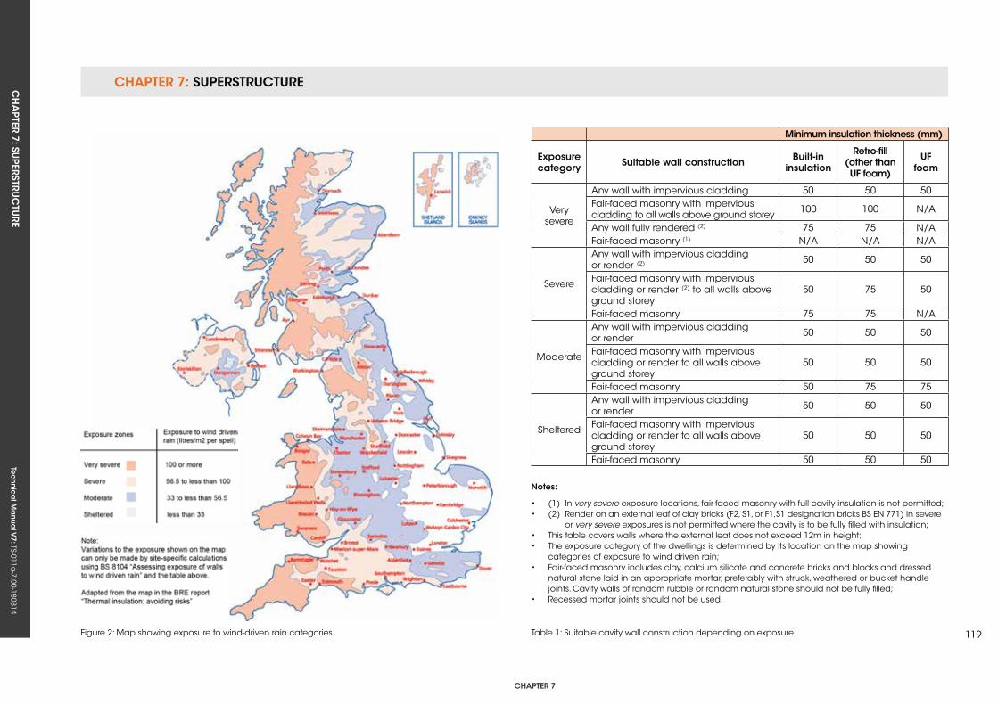
CHAPTER 7: SuPERSTRuCTuRECH
APTER 7: Su
PERSTRuC
TuRE
Tec
hn
ica
l Ma
nua
l V7: TS-011a
-7.00-180814
CHAPTER 7
119Figure 2: Map showing exposure to wind-driven rain categories Table 1: Suitable cavity wall construction depending on exposure
Minimum insulation thickness (mm)
exposure category suitable wall construction Built-in
insulation
retro-fill (other than uf foam)
uf foam
Very severe
Any wall with impervious cladding 50 50 50Fair-faced masonry with impervious cladding to all walls above ground storey 100 100 N/A
Any wall fully rendered (2) 75 75 N/AFair-faced masonry (1) N/A N/A N/A
Severe
Any wall with impervious cladding or render (2) 50 50 50
Fair-faced masonry with impervious cladding or render (2) to all walls above ground storey
50 75 50
Fair-faced masonry 75 75 N/A
Moderate
Any wall with impervious cladding or render 50 50 50
Fair-faced masonry with impervious cladding or render to all walls above ground storey
50 50 50
Fair-faced masonry 50 75 75
Sheltered
Any wall with impervious cladding or render 50 50 50
Fair-faced masonry with impervious cladding or render to all walls above ground storey
50 50 50
Fair-faced masonry 50 50 50
notes:
• (1) In very severe exposure locations, fair-faced masonry with full cavity insulation is not permitted;• (2) Render on an external leaf of clay bricks (F2, S1, or F1,S1 designation bricks BS EN 771) in severe or very severe exposures is not permitted where the cavity is to be fully filled with insulation;• This table covers walls where the external leaf does not exceed 12m in height;• The exposure category of the dwellings is determined by its location on the map showing categories of exposure to wind driven rain;• Fair-faced masonry includes clay, calcium silicate and concrete bricks and blocks and dressed natural stone laid in an appropriate mortar, preferably with struck, weathered or bucket handle joints. Cavity walls of random rubble or random natural stone should not be fully filled;• Recessed mortar joints should not be used.
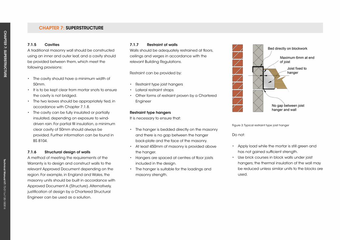
CHAPTER 7: SuPERSTRuCTuRE CH
APTER 7: Su
PERSTRuC
TuRE
Tec
hn
ica
l Ma
nua
l V7: TS-011a
-7.00-180814
7.1.5 CavitiesA traditional masonry wall should be constructed
using an inner and outer leaf, and a cavity should
be provided between them, which meet the
following provisions:
• The cavity should have a minimum width of
50mm.
• It is to be kept clear from mortar snots to ensure
the cavity is not bridged.
• The two leaves should be appropriately tied, in
accordance with Chapter 7.1.8.
• The cavity can be fully insulated or partially
insulated, depending on exposure to wind-
driven rain. For partial fill insulation, a minimum
clear cavity of 50mm should always be
provided. Further information can be found in
BS 8104.
7.1.6 structural design of wallsA method of meeting the requirements of the
Warranty is to design and construct walls to the
relevant Approved Document depending on the
region. For example, in England and Wales, the
masonry units should be built in accordance with
Approved Document A (Structure). Alternatively,
justification of design by a Chartered Structural
Engineer can be used as a solution.
7.1.7 restraint of wallsWalls should be adequately restrained at floors,
ceilings and verges in accordance with the
relevant Building Regulations.
Restraint can be provided by:
• Restraint type joist hangers
• Lateral restraint straps
• Other forms of restraint proven by a Chartered
Engineer
restraint type hangersIt is necessary to ensure that:
• The hanger is bedded directly on the masonry
and there is no gap between the hanger
back-plate and the face of the masonry.
• At least 450mm of masonry is provided above
the hanger.
• Hangers are spaced at centres of floor joists
included in the design.
• The hanger is suitable for the loadings and
masonry strength.
Do not:
• Apply load while the mortar is still green and
has not gained sufficient strength.
• use brick courses in block walls under joist
hangers; the thermal insulation of the wall may
be reduced unless similar units to the blocks are
used.
Figure 3: Typical restraint type joist hanger
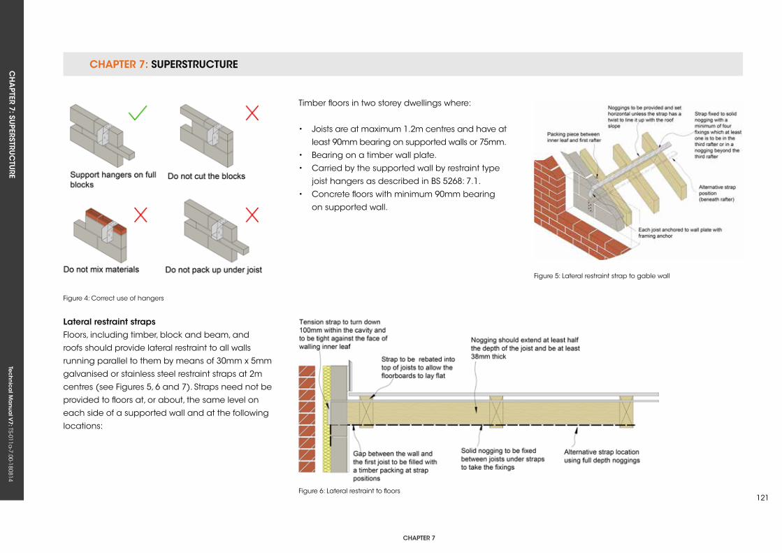
CHAPTER 7: SuPERSTRuCTuRECH
APTER 7: Su
PERSTRuC
TuRE
Tec
hn
ica
l Ma
nua
l V7: TS-011a
-7.00-180814
CHAPTER 7
121
Lateral restraint strapsFloors, including timber, block and beam, and
roofs should provide lateral restraint to all walls
running parallel to them by means of 30mm x 5mm
galvanised or stainless steel restraint straps at 2m
centres (see Figures 5, 6 and 7). Straps need not be
provided to floors at, or about, the same level on
each side of a supported wall and at the following
locations:
Figure 4: Correct use of hangers
Figure 6: Lateral restraint to floors
Timber floors in two storey dwellings where:
• Joists are at maximum 1.2m centres and have at
least 90mm bearing on supported walls or 75mm.
• Bearing on a timber wall plate.
• Carried by the supported wall by restraint type
joist hangers as described in BS 5268: 7.1.
• Concrete floors with minimum 90mm bearing
on supported wall.
Figure 5: Lateral restraint strap to gable wall
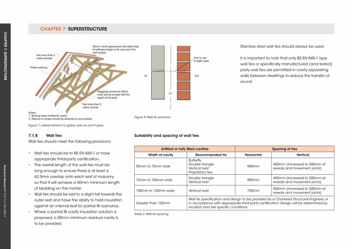
CHAPTER 7: SuPERSTRuCTuRE CH
APTER 7: Su
PERSTRuC
TuRE
Tec
hn
ica
l Ma
nua
l V7: TS-011a
-7.00-180814
Stainless steel wall ties should always be used.
It is important to note that only BS EN 845-1 type
wall ties or specifically manufactured (and tested)
party wall ties are permitted in cavity separating
walls between dwellings to reduce the transfer of
sound.
Figure 8: Wall tie provision
unfilled or fully filled cavities spacing of ties
Width of cavity recommended tie Horizontal vertical
50mm to 75mm wide
ButterflyDouble triangle Vertical twistProprietary ties
900mm 450mm (increased to 300mm at reveals and movement joints)
75mm to 100mm wide Double triangle Vertical twist 900mm 450mm (increased to 300mm at
reveals and movement joints)
100mm to 150mm wide Vertical twist 750mm 450mm (increased to 300mm at reveals and movement joints)
Greater than 150mmWall tie specification and design to be provided by a Chartered Structural Engineer, or in accordance with appropriate third party certification. Design will be determined by location and site specific conditions.
suitability and spacing of wall ties
Table 2: Wall tie spacing
7.1.8 Wall tiesWall ties should meet the following provisions:
• Wall ties should be to BS EN 845-1 or have
appropriate third-party certification.
• The overall length of the wall ties must be
long enough to ensure there is at least a
62.5mm overlap onto each leaf of masonry,
so that it will achieve a 50mm minimum length
of bedding on the mortar.
• Wall ties should be laid to a slight fall towards the
outer leaf and have the ability to hold insulation
against an internal leaf for partial fill scenarios.
• Where a partial fill cavity insulation solution is
proposed, a 50mm minimum residual cavity is
to be provided.
Figure 7: Lateral restraint to gable wall via roof trusses
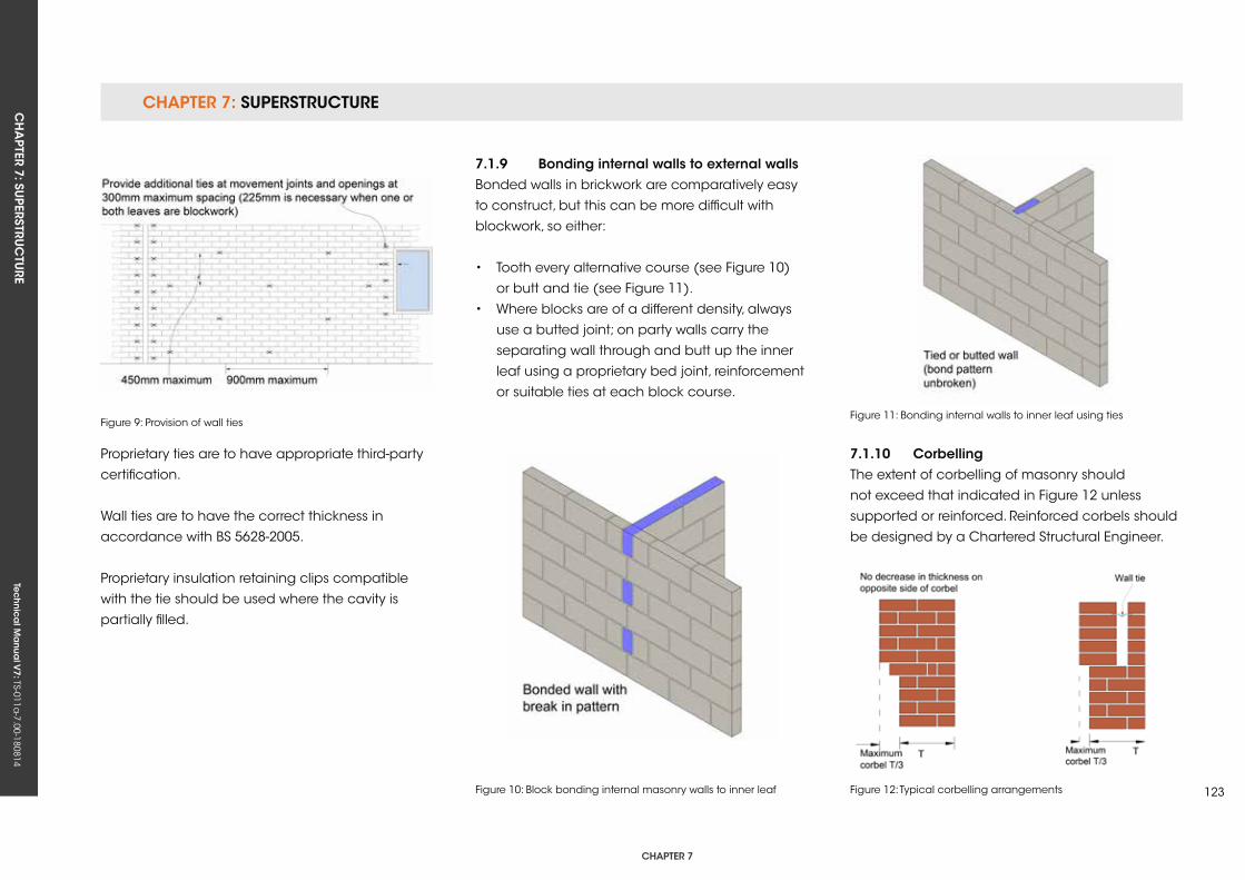
CHAPTER 7: SuPERSTRuCTuRECH
APTER 7: Su
PERSTRuC
TuRE
Tec
hn
ica
l Ma
nua
l V7: TS-011a
-7.00-180814
CHAPTER 7
123
7.1.9 Bonding internal walls to external wallsBonded walls in brickwork are comparatively easy
to construct, but this can be more difficult with
blockwork, so either:
• Tooth every alternative course (see Figure 10)
or butt and tie (see Figure 11).
• Where blocks are of a different density, always
use a butted joint; on party walls carry the
separating wall through and butt up the inner
leaf using a proprietary bed joint, reinforcement
or suitable ties at each block course.
Figure 10: Block bonding internal masonry walls to inner leaf Figure 12: Typical corbelling arrangements
Figure 11: Bonding internal walls to inner leaf using ties
7.1.10 CorbellingThe extent of corbelling of masonry should
not exceed that indicated in Figure 12 unless
supported or reinforced. Reinforced corbels should
be designed by a Chartered Structural Engineer.
Figure 9 - Provision of wall ties
Figure 9: Provision of wall ties
Proprietary ties are to have appropriate third-party
certification.
Wall ties are to have the correct thickness in
accordance with BS 5628-2005.
Proprietary insulation retaining clips compatible
with the tie should be used where the cavity is
partially filled.
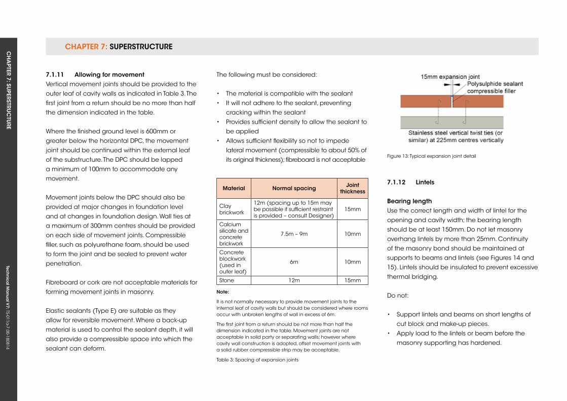
CHAPTER 7: SuPERSTRuCTuRE CH
APTER 7: Su
PERSTRuC
TuRE
Tec
hn
ica
l Ma
nua
l V7: TS-011a
-7.00-180814
The following must be considered:
• The material is compatible with the sealant
• It will not adhere to the sealant, preventing
cracking within the sealant
• Provides sufficient density to allow the sealant to
be applied
• Allows sufficient flexibility so not to impede
lateral movement (compressible to about 50% of
its original thickness); fibreboard is not acceptable
Material normal spacing Joint thickness
Claybrickwork
12m (spacing up to 15m may be possible if sufficient restraint is provided – consult Designer)
15mm
Calcium silicate andconcretebrickwork
7.5m – 9m 10mm
Concrete blockwork (used in outer leaf)
6m 10mm
Stone 12m 15mm
Table 3: Spacing of expansion joints
7.1.12 Lintels
Bearing lengthuse the correct length and width of lintel for the
opening and cavity width; the bearing length
should be at least 150mm. Do not let masonry
overhang lintels by more than 25mm. Continuity
of the masonry bond should be maintained at
supports to beams and lintels (see Figures 14 and
15). Lintels should be insulated to prevent excessive
thermal bridging.
Do not:
• Support lintels and beams on short lengths of
cut block and make-up pieces.
• Apply load to the lintels or beam before the
masonry supporting has hardened.
Figure 13: Typical expansion joint detail
note:
It is not normally necessary to provide movement joints to the internal leaf of cavity walls but should be considered where rooms occur with unbroken lengths of wall in excess of 6m.
The first joint from a return should be not more than half the dimension indicated in the table. Movement joints are not acceptable in solid party or separating walls; however where cavity wall construction is adopted, offset movement joints with a solid rubber compressible strip may be acceptable.
7.1.11 Allowing for movementVertical movement joints should be provided to the
outer leaf of cavity walls as indicated in Table 3. The
first joint from a return should be no more than half
the dimension indicated in the table.
Where the finished ground level is 600mm or
greater below the horizontal DPC, the movement
joint should be continued within the external leaf
of the substructure. The DPC should be lapped
a minimum of 100mm to accommodate any
movement.
Movement joints below the DPC should also be
provided at major changes in foundation level
and at changes in foundation design. Wall ties at
a maximum of 300mm centres should be provided
on each side of movement joints. Compressible
filler, such as polyurethane foam, should be used
to form the joint and be sealed to prevent water
penetration.
Fibreboard or cork are not acceptable materials for
forming movement joints in masonry.
Elastic sealants (Type E) are suitable as they
allow for reversible movement. Where a back-up
material is used to control the sealant depth, it will
also provide a compressible space into which the
sealant can deform.
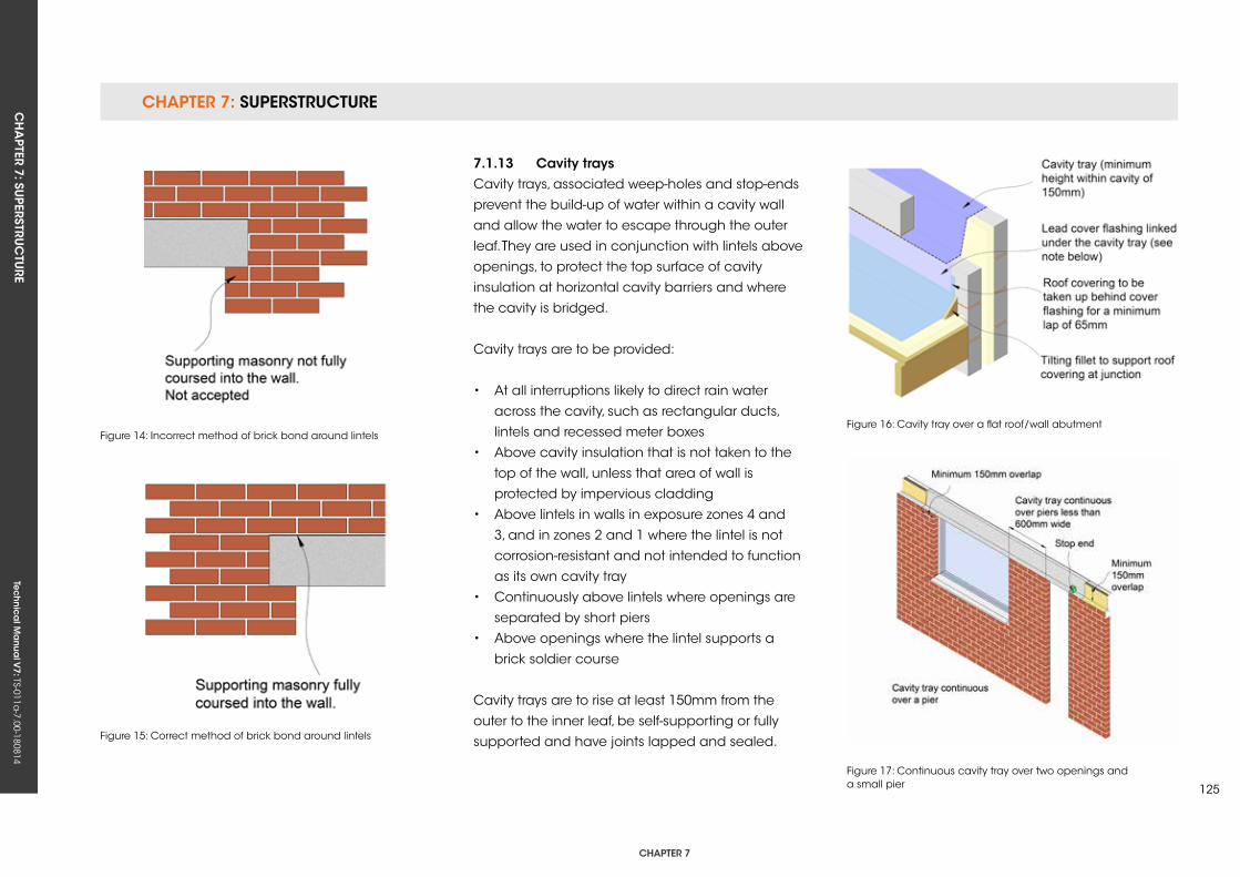
CHAPTER 7: SuPERSTRuCTuRECH
APTER 7: Su
PERSTRuC
TuRE
Tec
hn
ica
l Ma
nua
l V7: TS-011a
-7.00-180814
CHAPTER 7
125
7.1.13 Cavity traysCavity trays, associated weep-holes and stop-ends
prevent the build-up of water within a cavity wall
and allow the water to escape through the outer
leaf. They are used in conjunction with lintels above
openings, to protect the top surface of cavity
insulation at horizontal cavity barriers and where
the cavity is bridged.
Cavity trays are to be provided:
• At all interruptions likely to direct rain water
across the cavity, such as rectangular ducts,
lintels and recessed meter boxes
• Above cavity insulation that is not taken to the
top of the wall, unless that area of wall is
protected by impervious cladding
• Above lintels in walls in exposure zones 4 and
3, and in zones 2 and 1 where the lintel is not
corrosion-resistant and not intended to function
as its own cavity tray
• Continuously above lintels where openings are
separated by short piers
• Above openings where the lintel supports a
brick soldier course
Cavity trays are to rise at least 150mm from the
outer to the inner leaf, be self-supporting or fully
supported and have joints lapped and sealed.
Figure 16: Cavity tray over a flat roof/wall abutment
Figure 17: Continuous cavity tray over two openings and a small pier
Figure 14: Incorrect method of brick bond around lintels
Figure 15: Correct method of brick bond around lintels
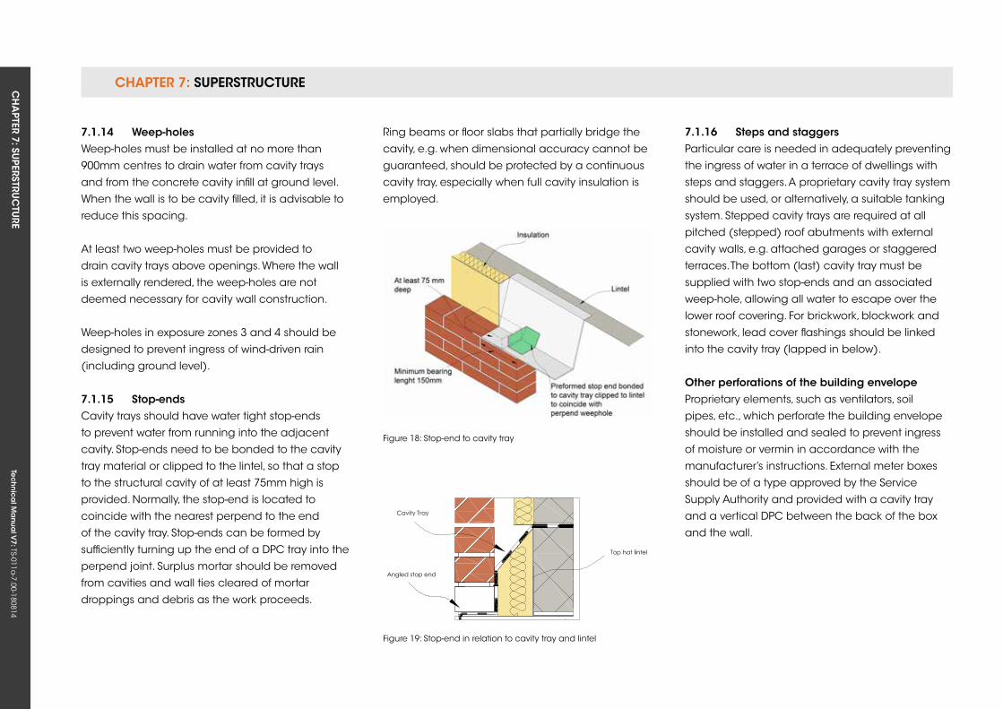
CHAPTER 7: SuPERSTRuCTuRE CH
APTER 7: Su
PERSTRuC
TuRE
Tec
hn
ica
l Ma
nua
l V7: TS-011a
-7.00-180814
Ring beams or floor slabs that partially bridge the
cavity, e.g. when dimensional accuracy cannot be
guaranteed, should be protected by a continuous
cavity tray, especially when full cavity insulation is
employed.
Figure 18: Stop-end to cavity tray
Figure 19: Stop-end in relation to cavity tray and lintel
7.1.16 steps and staggersParticular care is needed in adequately preventing
the ingress of water in a terrace of dwellings with
steps and staggers. A proprietary cavity tray system
should be used, or alternatively, a suitable tanking
system. Stepped cavity trays are required at all
pitched (stepped) roof abutments with external
cavity walls, e.g. attached garages or staggered
terraces. The bottom (last) cavity tray must be
supplied with two stop-ends and an associated
weep-hole, allowing all water to escape over the
lower roof covering. For brickwork, blockwork and
stonework, lead cover flashings should be linked
into the cavity tray (lapped in below).
other perforations of the building envelopeProprietary elements, such as ventilators, soil
pipes, etc., which perforate the building envelope
should be installed and sealed to prevent ingress
of moisture or vermin in accordance with the
manufacturer’s instructions. External meter boxes
should be of a type approved by the Service
Supply Authority and provided with a cavity tray
and a vertical DPC between the back of the box
and the wall.
7.1.14 Weep-holesWeep-holes must be installed at no more than
900mm centres to drain water from cavity trays
and from the concrete cavity infill at ground level.
When the wall is to be cavity filled, it is advisable to
reduce this spacing.
At least two weep-holes must be provided to
drain cavity trays above openings. Where the wall
is externally rendered, the weep-holes are not
deemed necessary for cavity wall construction.
Weep-holes in exposure zones 3 and 4 should be
designed to prevent ingress of wind-driven rain
(including ground level).
7.1.15 stop-endsCavity trays should have water tight stop-ends
to prevent water from running into the adjacent
cavity. Stop-ends need to be bonded to the cavity
tray material or clipped to the lintel, so that a stop
to the structural cavity of at least 75mm high is
provided. Normally, the stop-end is located to
coincide with the nearest perpend to the end
of the cavity tray. Stop-ends can be formed by
sufficiently turning up the end of a DPC tray into the
perpend joint. Surplus mortar should be removed
from cavities and wall ties cleared of mortar
droppings and debris as the work proceeds.
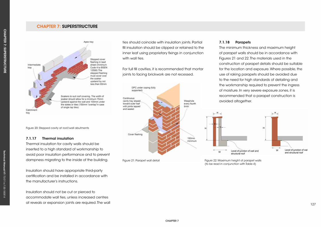
CHAPTER 7: SuPERSTRuCTuRECH
APTER 7: Su
PERSTRuC
TuRE
Tec
hn
ica
l Ma
nua
l V7: TS-011a
-7.00-180814
CHAPTER 7
127
ties should coincide with insulation joints. Partial
fill insulation should be clipped or retained to the
inner leaf using proprietary fixings in conjunction
with wall ties.
For full fill cavities, it is recommended that mortar
joints to facing brickwork are not recessed.
Figure 21: Parapet wall detail Figure 22: Maximum height of parapet walls (to be read in conjunction with Table 4)
7.1.17 Thermal insulationThermal insulation for cavity walls should be
inserted to a high standard of workmanship to
avoid poor insulation performance and to prevent
dampness migrating to the inside of the building.
Insulation should have appropriate third-party
certification and be installed in accordance with
the manufacturer’s instructions.
Insulation should not be cut or pierced to
accommodate wall ties, unless increased centres
at reveals or expansion joints are required. The wall
Figure 20: Stepped cavity at roof/wall abutments
7.1.18 ParapetsThe minimum thickness and maximum height
of parapet walls should be in accordance with
Figures 21 and 22. The materials used in the
construction of parapet details should be suitable
for the location and exposure. Where possible, the
use of raking parapets should be avoided due
to the need for high standards of detailing and
the workmanship required to prevent the ingress
of moisture. In very severe exposure zones, it is
recommended that a parapet construction is
avoided altogether.
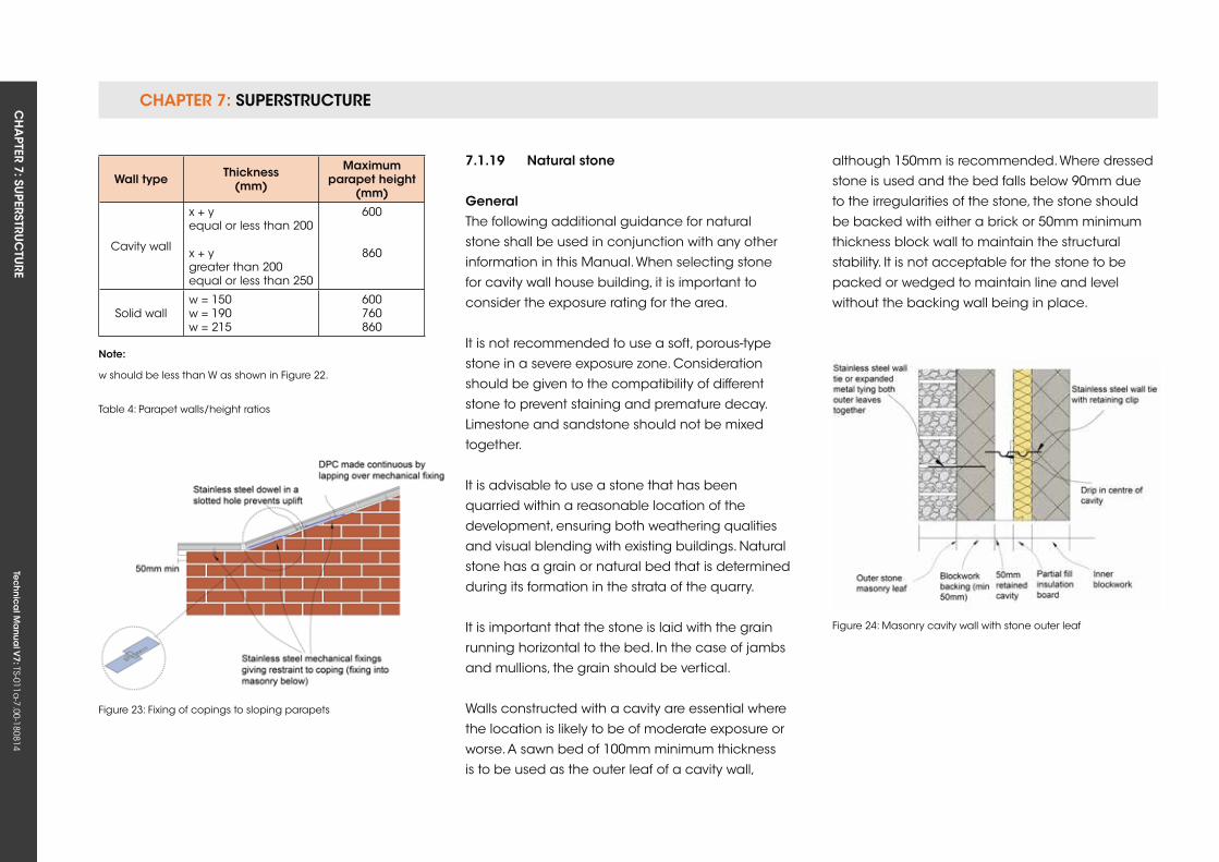
CHAPTER 7: SuPERSTRuCTuRE CH
APTER 7: Su
PERSTRuC
TuRE
Tec
hn
ica
l Ma
nua
l V7: TS-011a
-7.00-180814
7.1.19 natural stone
generalThe following additional guidance for natural
stone shall be used in conjunction with any other
information in this Manual. When selecting stone
for cavity wall house building, it is important to
consider the exposure rating for the area.
It is not recommended to use a soft, porous-type
stone in a severe exposure zone. Consideration
should be given to the compatibility of different
stone to prevent staining and premature decay.
Limestone and sandstone should not be mixed
together.
It is advisable to use a stone that has been
quarried within a reasonable location of the
development, ensuring both weathering qualities
and visual blending with existing buildings. Natural
stone has a grain or natural bed that is determined
during its formation in the strata of the quarry.
It is important that the stone is laid with the grain
running horizontal to the bed. In the case of jambs
and mullions, the grain should be vertical.
Walls constructed with a cavity are essential where
the location is likely to be of moderate exposure or
worse. A sawn bed of 100mm minimum thickness
is to be used as the outer leaf of a cavity wall,
although 150mm is recommended. Where dressed
stone is used and the bed falls below 90mm due
to the irregularities of the stone, the stone should
be backed with either a brick or 50mm minimum
thickness block wall to maintain the structural
stability. It is not acceptable for the stone to be
packed or wedged to maintain line and level
without the backing wall being in place.
Figure 24: Masonry cavity wall with stone outer leaf
Figure 23: Fixing of copings to sloping parapets
Wall type Thickness (mm)
Maximum parapet height
(mm)
Cavity wall
x + yequal or less than 200
x + ygreater than 200equal or less than 250
600
860
Solid wallw = 150w = 190w = 215
600760860
note:
w should be less than W as shown in Figure 22.
Table 4: Parapet walls/height ratios
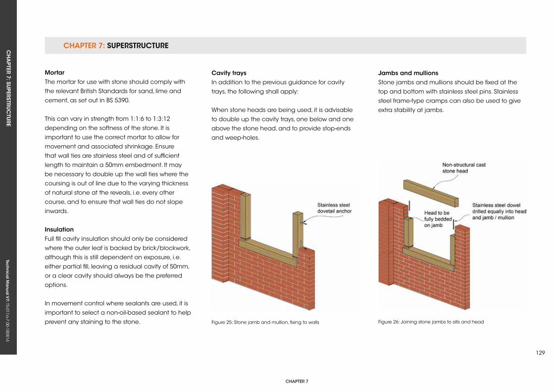
CHAPTER 7: SuPERSTRuCTuRECH
APTER 7: Su
PERSTRuC
TuRE
Tec
hn
ica
l Ma
nua
l V7: TS-011a
-7.00-180814
CHAPTER 7
129
Cavity traysIn addition to the previous guidance for cavity
trays, the following shall apply:
When stone heads are being used, it is advisable
to double up the cavity trays, one below and one
above the stone head, and to provide stop-ends
and weep-holes.
Figure 25: Stone jamb and mullion, fixing to walls Figure 26: Joining stone jambs to sills and head
MortarThe mortar for use with stone should comply with
the relevant British Standards for sand, lime and
cement, as set out in BS 5390.
This can vary in strength from 1:1:6 to 1:3:12
depending on the softness of the stone. It is
important to use the correct mortar to allow for
movement and associated shrinkage. Ensure
that wall ties are stainless steel and of sufficient
length to maintain a 50mm embedment. It may
be necessary to double up the wall ties where the
coursing is out of line due to the varying thickness
of natural stone at the reveals, i.e. every other
course, and to ensure that wall ties do not slope
inwards.
insulationFull fill cavity insulation should only be considered
where the outer leaf is backed by brick/blockwork,
although this is still dependent on exposure, i.e.
either partial fill, leaving a residual cavity of 50mm,
or a clear cavity should always be the preferred
options.
In movement control where sealants are used, it is
important to select a non-oil-based sealant to help
prevent any staining to the stone.
Jambs and mullionsStone jambs and mullions should be fixed at the
top and bottom with stainless steel pins. Stainless
steel frame-type cramps can also be used to give
extra stability at jambs.
Tec
hn
ica
l Ma
nua
l V6: TS-011a
-6.00-010413Te
ch
nic
al M
anu
al V
7: TS-011a-7.00-180814
FUNCTIONAL REQUIREMENTS
Workmanshipi. All workmanship must be within the tolerances defined in Chapter 1
of this Manual.
ii. All work is to be carried out by a technically competent person in
a workmanlike manner.
Materialsi. All materials should be stored correctly in a manner that will not cause
damage or deterioration of the product.
ii. All materials, products and building systems shall be appropriate and
suitable for their intended purpose.
iii. Steel frames should be appropriately treated to prevent corrosion.
iv. The structure shall, unless specifically agreed otherwise with the
Warranty provider, have a life of not less than 60 years. Individual
components and assemblies, not integral to the structure, may have a
lesser durability, but not in any circumstances less than 15 years.
Designi. The design and specifications shall provide a clear indication of the
design intent and demonstrate a satisfactory level of performance.
ii. The design of the steel frame must be supported by structural
calculations completed by a suitably qualified engineer. The design
and construction must meet the relevant Building Regulations, British
Standards, Eurocodes and other statutory requirements.
7.2 sTeeL frAMe
CHAPTER 7: SuPERSTRuCTuRECH
APTER 7: Su
PERSTRuC
TuRE
Tec
hn
ica
l Ma
nua
l V7: TS-011a
-7.00-180814
CHAPTER 7
131
7.2.1 steel frame Galvanised strip steel should be designated
either grade S280GD or 350GD to BS EN 10326.
The structural design should be in accordance
with BS 5950–5: 1998, and imposed loads should
be calculated in accordance with BS EN 1991,
including:
• Dead loads
• Imposed loads
• Wind loads
Steel and fixings should be suitable for the design
and adequately protected against corrosion. Load-
bearing walls should be designed to support and
transfer loads to foundations safely and without
undue movement.
Wall panels may provide resistance to racking
forces using one or more of the following
techniques:
• Internal bracing
• Cross flat bracing
• External sheathing board
• Internal sheathing board
• Rigid frame action
The design should detail how joints between the wall
panels and other elements are to be securely fixed:
• To the structure
• To adjacent panels
• To the floor and roof
The design should ensure that the structure is
adequately protected from the effects of moisture.
Exterior claddings should be compatible with the
steel frame. Suspended floors should be designed
to support and transmit loads safely to the
supporting structure without undue deflection.
Services should be adequately protected from
damage. Walls and floors should resist the spread
of fire. Internal walls and floors should be designed
to resist the passage of sound adequately.
7.2.2 site tolerancesIt is essential that the accuracy of setting out
foundations and ground beams are checked well
in advance of materials being delivered to site.
For accurate erection of the frame, the following
tolerances are required at the level of the base of
the wall frame:
• Length of wall frame: +/-10mm in 10m.
• Line of wall frame: +/-5mm from outer face
of plate.
• Level of base of wall frame: +/-5mm over
complete wall line.
Some packing may be needed to achieve the
required tolerances:
• Less than 10mm; pack under each steel with
pre-galvanised steel shims.
• 10mm–20mm; pack under each steel with
steel shims and grout over length of sole plate.
• Over 20mm; refer to Frame Designer.
7.2.3 fixing of frames to substructuresThe oversite DPM should be attached to the side
of the slab and returned under the DPC on which
the frame is placed. The DPC/DPM detail requires
careful attention to prevent the cavity being bridged
and providing a ledge for mortar droppings.
Holding down anchors may be galvanised, or
preferably stainless steel straps that are fixed to the
stud wall and attached to masonry supports or
concrete foundation, or holding down bolts fixed to
the concrete slab.
7.2.4 WallsIf stainless steel straps are used, they should be
grade 1.4301 steel to BS EN 10088 and isolated
from the studs with neoprene gaskets or similar.
Non-stainless connections should be isolated from
the straps with suitable grommets and washers.
CHAPTER 7: SuPERSTRuCTuRE CH
APTER 7: Su
PERSTRuC
TuRE
Tec
hn
ica
l Ma
nua
l V7: TS-011a
-7.00-180814
Resin or expanding anchors should be used in
an in-situ concrete raft of a minimum C20/GEN3
grade concrete. If required, steel frames can be
fixed to timber sole plates.
For guidance on fixing sole plates, refer to the
timber frame section in this Manual. The metal
frame should be located entirely above DPC
level. Where this is not possible, Z460 galvanising
or equivalent, or a suitable bituminous coating,
should be applied to all components below DPC
level. It is recommended that the inner leaf DPC
is turned up approximately 30mm above the
screed to protect the bottom of the studs from
construction moisture and spillage, and weep-
holes are provided at 900mm centres to drain
cavities at ground level.
7.2.5 Metal stud frameworkThe wall panel usually consists of a head rail, base
rail (sole plate) and possibly horizontal noggins at
mid-height, together with vertical wall studs:
• Recommended site connections include self-
drilling, self-tapping screws or 10mm–12mm
diameter grade 4.6 bolts. Welding is not
recommended on-site.
• Workmanship should comply with BS 8000: 5.
• Framed walls should be accurately aligned,
plumb, level without twist and securely fixed to
adjacent elements.
Vertical tolerances are:
• +/-15mm in overall height of wall 3 storey or
• +/-10mm in overall height of wall 2 storey or
• +/-5mm in storey height (approx. 2.5m)
A lintel should be provided where one or more
studs is cut or displaced to form an opening.
A lintel is not required where an opening falls
between studs. Non-load-bearing walls should
have adequate strength and support.
Non-load-bearing walls should not bridge
movement joints in the main structure. A movement
joint should be constructed between the frame
and any chimney flue lift shaft to prevent load
transfer. Cavity barriers and fire stops should be
provided in accordance with relevant Building
Regulations, and steel joists should be spaced at
centres no greater than 600mm.
Cutting holes for services on-site is not
recommended, but where essential should be
carried out with specialist tools. The maximum size
of rectangular holes should not exceed 40% of the
overall section, and length should not exceed 60%
of the overall section or be the depth of the section
apart. No holes should be closer than 1.5 times
the depth of the section to the end of the member.
Notches are not acceptable.
7.2.6 Thermal insulationRigid thermal insulation material should be fixed
to the outside face of the steel studs to create a
‘warm frame’ construction.
Where the condensation risk has been assessed
and shown to be negligible, additional insulation
may be placed between the studs. The additional
insulation should be placed in contact with the
studs to minimise air gaps and prevent local
condensation.
The following are acceptable:
• Mineral wool to BS EN 13162
• FR (flame retardant) grade expanded
polystyrene to BS EN 13163
• FR (flame retardant) grade extruded polystyrene
to BS EN 13164
• Rigid polyurethane foam and polyisocyanurate
to BS EN 13166
• Cellular glass to BS EN 13167
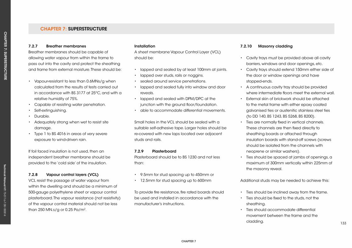
CHAPTER 7: SuPERSTRuCTuRECH
APTER 7: Su
PERSTRuC
TuRE
Tec
hn
ica
l Ma
nua
l V7: TS-011a
-7.00-180814
CHAPTER 7
133
7.2.7 Breather membranesBreather membranes should be capable of
allowing water vapour from within the frame to
pass out into the cavity and protect the sheathing
and frame from external moisture. These should be:
• Vapour-resistant to less than 0.6MNs/g when
calculated from the results of tests carried out
in accordance with BS 3177 at 25ºC, and with a
relative humidity of 75%.
• Capable of resisting water penetration.
• Self-extinguishing.
• Durable.
• Adequately strong when wet to resist site
damage.
• Type 1 to BS 4016 in areas of very severe
exposure to wind-driven rain.
If foil faced insulation is not used, then an
independent breather membrane should be
provided to the ‘cold side’ of the insulation.
7.2.8 vapour control layers (vCL)VCL resist the passage of water vapour from
within the dwelling and should be a minimum of
500-gauge polyethylene sheet or vapour control
plasterboard. The vapour resistance (not resistivity)
of the vapour control material should not be less
than 250 MN.s/g or 0.25 Pa/m2.
installationA sheet membrane Vapour Control Layer (VCL)
should be:
• lapped and sealed by at least 100mm at joints.
• lapped over studs, rails or noggins.
• sealed around service penetrations.
• lapped and sealed fully into window and door
reveals.
• lapped and sealed with DPM/DPC at the
junction with the ground floor/foundation.
• able to accommodate differential movements.
Small holes in the VCL should be sealed with a
suitable self-adhesive tape. Larger holes should be
re-covered with new laps located over adjacent
studs and rails.
7.2.9 PlasterboardPlasterboard should be to BS 1230 and not less
than:
• 9.5mm for stud spacing up to 450mm or
• 12.5mm for stud spacing up to 600mm
To provide fire resistance, fire rated boards should
be used and installed in accordance with the
manufacturer’s instructions.
7.2.10 Masonry cladding
• Cavity trays must be provided above all cavity
barriers, windows and door openings, etc.
• Cavity trays should extend 150mm either side of
the door or window openings and have
stopped-ends.
• A continuous cavity tray should be provided
where intermediate floors meet the external wall.
• External skin of brickwork should be attached
to the metal frame with either epoxy coated
galvanised ties or austenitic stainless steel ties
(to DD 140, BS 1243, BS 5268, BS 8200).
• Ties are normally fixed in vertical channels.
These channels are then fixed directly to
sheathing boards or attached through
insulation boards with stand-off screws (screws
should be isolated from the channels with
neoprene or similar washers).
• Ties should be spaced at jambs of openings, a
maximum of 300mm vertically within 225mm of
the masonry reveal.
Additional studs may be needed to achieve this:
• Ties should be inclined away from the frame.
• Ties should be fixed to the studs, not the
sheathing.
• Ties should accommodate differential
movement between the frame and the
cladding.
CHAPTER 7: SuPERSTRuCTuRE CH
APTER 7: Su
PERSTRuC
TuRE
Tec
hn
ica
l Ma
nua
l V7: TS-011a
-7.00-180814
• Soft joints should be provided to allow for
differential movement. A gap of 1mm per metre
of masonry should be provided at openings
and soffits.
• All brick support angles should be installed by
the manufacturer or Specialist Contractor.
7.2.11 CladdingsMore traditional claddings can include, amongst
others, timber boarding, plywood and tile hanging.
These types of cladding should be fixed to battens
and suitably attached at stud positions. For further
details, refer to the timber frame section of this
Manual and the manufacturer’s recommendations.
Render on metal lath combined with a breather
membrane should also be fixed to battens
attached to studs.
Breather membranes should be provided in areas
of severe exposure or worse.
Other claddings should only be used if they
are provided with an acceptable third-party
accreditation certificate.
Tec
hn
ica
l Ma
nua
l V6: TS-011a
-6.00-010413Te
ch
nic
al M
anu
al V
7: TS-011a-7.00-180814
FUNCTIONAL REQUIREMENTS
135
7.3 TiMBer frAMe
Workmanshipi. All workmanship must be within the tolerances defined in Chapter 1
of this Manual.
ii. All work is to be carried out by a technically competent person in
a workmanlike manner.
iii. Certification is required for any work completed by an approved
installer.
Materialsi. All materials should be stored correctly in a manner that will not cause
damage or deterioration of the product. Timber frame elements
should be appropriately covered to keep components dry.
ii. All materials, products and building systems shall be appropriate and
suitable for their intended purpose.
iii. The structure shall, unless specifically agreed otherwise with the
Warranty provider, have a life of not less than 60 years. Individual
components and assemblies, not integral to the structure, may have a
lesser durability, but not in any circumstances less than 15 years.
Designi. The design and specifications shall provide a clear indication of
the design intent and demonstrate a satisfactory level of performance,
supported by structural calculations provided by a suitably qualified
expert.
ii. The materials, design and construction must meet the relevant
Building Regulations, British Standards, Eurocodes and other statutory
requirements.
iii. Any off-site manufactured engineered beams/posts must have
structural calculations endorsed by the manufacturer.
CHAPTer 7
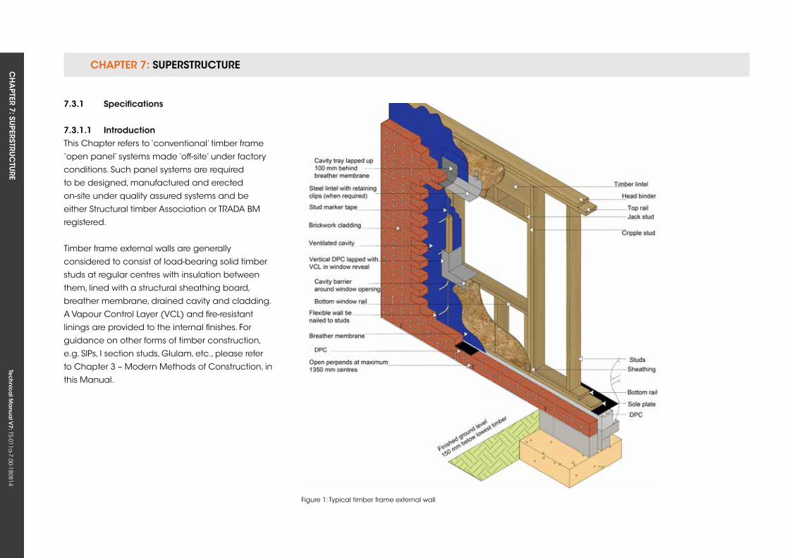
CHAPTER 7: SuPERSTRuCTuRE CH
APTER 7: Su
PERSTRuC
TuRE
Tec
hn
ica
l Ma
nua
l V7: TS-011a
-7.00-180814
7.3.1 specifications
7.3.1.1 introductionThis Chapter refers to ‘conventional’ timber frame
‘open panel’ systems made ‘off-site’ under factory
conditions. Such panel systems are required
to be designed, manufactured and erected
on-site under quality assured systems and be
either Structural timber Association or TRADA BM
registered.
Timber frame external walls are generally
considered to consist of load-bearing solid timber
studs at regular centres with insulation between
them, lined with a structural sheathing board,
breather membrane, drained cavity and cladding.
A Vapour Control Layer (VCL) and fire-resistant
linings are provided to the internal finishes. For
guidance on other forms of timber construction,
e.g. SIPs, I section studs, Glulam, etc., please refer
to Chapter 3 – Modern Methods of Construction, in
this Manual.
Figure 1: Typical timber frame external wall
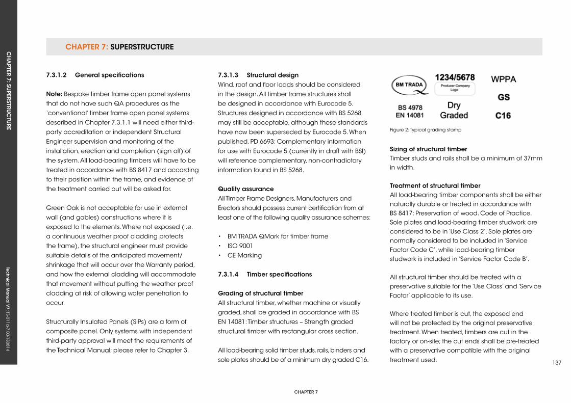
CHAPTER 7: SuPERSTRuCTuRECH
APTER 7: Su
PERSTRuC
TuRE
Tec
hn
ica
l Ma
nua
l V7: TS-011a
-7.00-180814
CHAPTER 7
137
7.3.1.2 general specifications
note: Bespoke timber frame open panel systems
that do not have such qA procedures as the
‘conventional’ timber frame open panel systems
described in Chapter 7.3.1.1 will need either third-
party accreditation or independent Structural
Engineer supervision and monitoring of the
installation, erection and completion (sign off) of
the system. All load-bearing timbers will have to be
treated in accordance with BS 8417 and according
to their position within the frame, and evidence of
the treatment carried out will be asked for.
Green Oak is not acceptable for use in external
wall (and gables) constructions where it is
exposed to the elements. Where not exposed (i.e.
a continuous weather proof cladding protects
the frame), the structural engineer must provide
suitable details of the anticipated movement/
shrinkage that will occur over the Warranty period,
and how the external cladding will accommodate
that movement without putting the weather proof
cladding at risk of allowing water penetration to
occur.
Structurally Insulated Panels (SIPs) are a form of
composite panel. Only systems with independent
third-party approval will meet the requirements of
the Technical Manual; please refer to Chapter 3.
7.3.1.3 structural designWind, roof and floor loads should be considered
in the design. All timber frame structures shall
be designed in accordance with Eurocode 5.
Structures designed in accordance with BS 5268
may still be acceptable, although these standards
have now been superseded by Eurocode 5. When
published, PD 6693: Complementary information
for use with Eurocode 5 (currently in draft with BSI)
will reference complementary, non-contradictory
information found in BS 5268.
Quality assuranceAll Timber Frame Designers, Manufacturers and
Erectors should possess current certification from at
least one of the following quality assurance schemes:
• BM TRADA qMark for timber frame
• ISO 9001
• CE Marking
7.3.1.4 Timber specifications
grading of structural timberAll structural timber, whether machine or visually
graded, shall be graded in accordance with BS
EN 14081: Timber structures – Strength graded
structural timber with rectangular cross section.
All load-bearing solid timber studs, rails, binders and
sole plates should be of a minimum dry graded C16.
Figure 2: Typical grading stamp
sizing of structural timberTimber studs and rails shall be a minimum of 37mm in width.
Treatment of structural timberAll load-bearing timber components shall be either naturally durable or treated in accordance with BS 8417: Preservation of wood. Code of Practice. Sole plates and load-bearing timber studwork are considered to be in ‘use Class 2’. Sole plates are normally considered to be included in ‘Service Factor Code C’, while load-bearing timber studwork is included in ‘Service Factor Code B’.
All structural timber should be treated with a preservative suitable for the ‘use Class’ and ‘Service Factor’ applicable to its use.
Where treated timber is cut, the exposed end will not be protected by the original preservative treatment. When treated, timbers are cut in the factory or on-site; the cut ends shall be pre-treated with a preservative compatible with the original
treatment used.
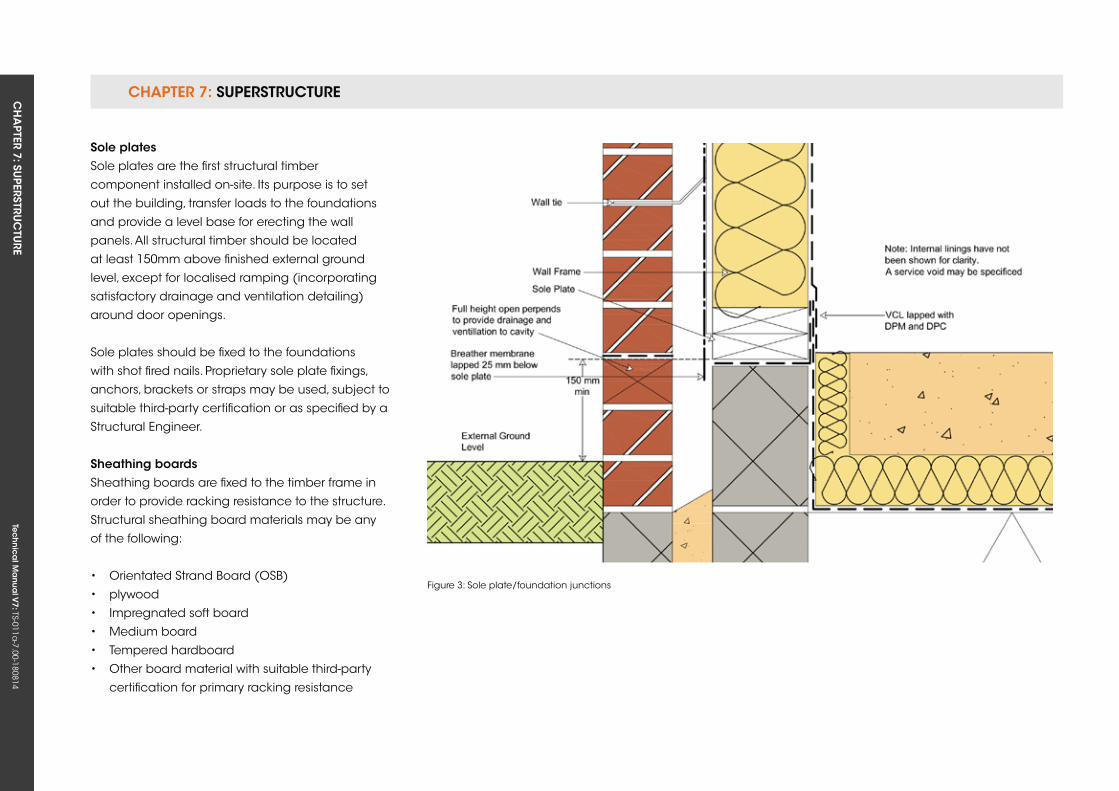
CHAPTER 7: SuPERSTRuCTuRE CH
APTER 7: Su
PERSTRuC
TuRE
Tec
hn
ica
l Ma
nua
l V7: TS-011a
-7.00-180814
sole plates Sole plates are the first structural timber
component installed on-site. Its purpose is to set
out the building, transfer loads to the foundations
and provide a level base for erecting the wall
panels. All structural timber should be located
at least 150mm above finished external ground
level, except for localised ramping (incorporating
satisfactory drainage and ventilation detailing)
around door openings.
Sole plates should be fixed to the foundations
with shot fired nails. Proprietary sole plate fixings,
anchors, brackets or straps may be used, subject to
suitable third-party certification or as specified by a
Structural Engineer.
sheathing boardsSheathing boards are fixed to the timber frame in
order to provide racking resistance to the structure.
Structural sheathing board materials may be any
of the following:
• Orientated Strand Board (OSB)
• plywood
• Impregnated soft board
• Medium board
• Tempered hardboard
• Other board material with suitable third-party
certification for primary racking resistance
Figure 3: Sole plate/foundation junctions
CHAPTER 7: SuPERSTRuCTuRECH
APTER 7: Su
PERSTRuC
TuRE
Tec
hn
ica
l Ma
nua
l V7: TS-011a
-7.00-180814
CHAPTER 7
139
All wood-based panel products should comply with BS EN 13986: Wood-based panels for use in construction – Characteristics, evaluation of conformity and marking.
OSB should be grade 3 or 4 in accordance with BS EN 300: Oriented Strand Boards (OSB) –Definitions, classification and specifications.
Plywood should be Class 3 Structural in accordance with BS EN 636: Plywood Specifications.
Impregnated soft boards should be Type SB.HLS in accordance with BS EN 622-4: Fibreboards. Specifications. Requirements for soft boards.
Medium board should be type MBH.HLS1 or MBH.HLS2 in accordance with BS EN 622-3: Fibreboards. Specifications. Requirements for medium boards.
Tempered hardboards should be Type HB.HLA1 or HB.HLA2 in accordance with BS EN 622-2: Fibreboards. Specifications. Requirements for hardboards.
7.3.1.5 other material specifications
fixingsAll sole plate fixings and holding down products should be austenitic stainless steel.
Timber components and structural sheathing
boards may be fixed with:
• Nails
• Staples
Nail fixings should be:
• Austenitic stainless steel
• Galvanised
• Sheradised
Staple fixings should be austenitic stainless steel or
similar.
Breather membraneA breather membrane is a water-resistant, moisture
vapour permeable membrane used to provide
temporary weather protection during construction,
and secondary protection from moisture once the
building is complete.
The timber frame structure should always be
protected by a breather membrane.
Breather membranes should be:
• A Type 1 membrane in accordance with
BS 4016: Specifications for flexible building
membranes (breather type).
• Self-extinguishing.• Securely fixed to protect the outside face of the timber frame structure with austenitic stainless steel staples.
Cavity barriersCavity barriers are required to prevent the spread of smoke and flame within concealed spaces.
Cavity barriers may be constructed from:
• Steel at least 0.5mm thick• Timber at least 38mm thick• Polythene sleeved mineral wool• Mineral wool slab• Calcium silicate, cement-based or gypsum-based board at least 12mm thick• An independently assessed and certified proprietary product
insulation materialsInsulation materials should be chosen with consideration for their breathability and interaction with the timber frame.
Thermal insulation products typically used are:
• Mineral fibre (glass or rock)• Wood fibre/wool
• Blown cellulose
Other insulation materials may be used, subject to
relevant third-party certification.
Insulation may be specified in any or all of the
following locations:
CHAPTER 7: SuPERSTRuCTuRE CH
APTER 7: Su
PERSTRuC
TuRE
Tec
hn
ica
l Ma
nua
l V7: TS-011a
-7.00-180814
• Between the load-bearing studs
• On the outside of the timber frame
• On the inside of the timber frame
Insulation installed to the outside of the timber
frame structure should have third-party certification
for this application and retain a clear cavity
dimension, as detailed in Table 1 in Chapter 7.3.4.
External walls should be subject to u-Value and
condensation risk calculations. A wall build up will
be considered satisfactory if there is no calculated
risk of surface or interstitial condensation at any
time of the year, and it fulfils the minimum National
Requirement for thermal performance.
Special consideration should be given to
condensation risk where non-breathable insulation
products are installed on the outside of the timber
frame structure.
vapour Control Layer (vCL)A VCL is a moisture vapour-resistant material
located on or near the warm side of the thermal
insulation.
Its purpose is to:
• Restrict the passage of moisture vapour through
the structure of the wall
• Mitigate the risk of interstitial condensation
The VCL should have a minimum vapour resistance
of 250 MN.s/g or 0.25 Pa/m2. It is also typically used
as an air tightness layer.
The VCL may take the form of:
• A vapour control plasterboard comprising a
metallised polyester film bonded to the back
face of the plasterboard.
• A minimum 125 micron thick (500 gauge)
polythene sheet.
• A third-party approved proprietary vapour
control membrane product.
Subject to a favourable condensation risk analysis,
a novel or reverse wall construction may not
require the use of a high moisture vapour-resistant
vapour control membrane.
Wall liningsThe internal lining of the timber frame wall may be
required to perform four functions:
• Provide the finish or a substrate to accept the
finish on the inner face of the wall.
• Contribute to the racking resistance of the wall.
• Contribute to the fire resistance of the wall.
• Contribute to the acoustic performance
of the wall.
Wall linings are typically:
• Gypsum plasterboard
• Cement bonded particle board
Other lining materials may be used subject to
the material satisfying any relevant performance
criteria, e.g. fire resistance, and possessing relevant
third-party certification.
Masonry supporting timber frame, foundations, kerb upstands, etc.Foundations and masonry supporting timber
frame structures should be in accordance with the
relevant Technical Manual Chapter, as indicated
below:
• Chapter 2 – Materials
• Chapter 4 – Site Investigation
• Chapter 5 – Foundations
• Chapter 6 – Substructure
• Chapter 7 – Superstructure
CladdingsTimber frame external walls should be finished
externally with a cladding system, which may take
the form of masonry or a lightweight rain screen
system. Regardless of the cladding system used, a
cavity with provision for drainage and ventilation
should be provided between the cladding and the
timber frame.

CHAPTER 7: SuPERSTRuCTuRECH
APTER 7: Su
PERSTRuC
TuRE
Tec
hn
ica
l Ma
nua
l V7: TS-011a
-7.00-180814
CHAPTER 7
141
Wall tiesExternal wall ties and fixings between the timber
frame and masonry cladding shall:
• Comply with BS EN 845: Specification for
ancillary components for masonry. Ties, tension
straps, hangers and brackets.
• Be constructed from austenitic stainless steel
• Accommodate all anticipated differential
movement.
• Be of adequate length and masonry bond to
provide a clear cavity of at least 50mm.
7.3.2 Manufacture
7.3.2.1 TimberAll structural timber components should be
specified in accordance with the requirements of
Chapter 7.3.1.
Timber frame external wall panels shall:
• Be manufactured in accordance with the
Structural Engineer’s design.
• Consist of solid timber studs and rails.
• Have studs at a maximum of 600mm centres.
• Be braced with a structural sheathing board.
Figure 4: Typical wall panel
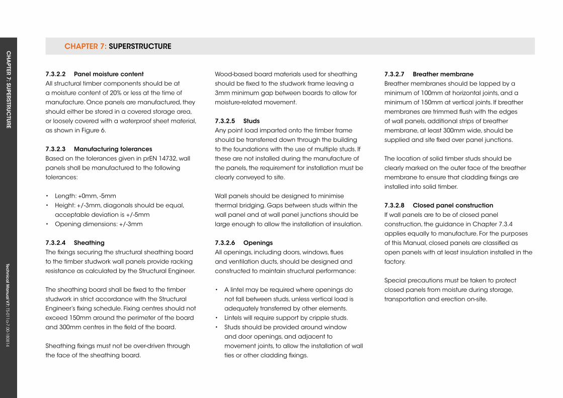
CHAPTER 7: SuPERSTRuCTuRE CH
APTER 7: Su
PERSTRuC
TuRE
Tec
hn
ica
l Ma
nua
l V7: TS-011a
-7.00-180814
7.3.2.2 Panel moisture contentAll structural timber components should be at
a moisture content of 20% or less at the time of
manufacture. Once panels are manufactured, they
should either be stored in a covered storage area,
or loosely covered with a waterproof sheet material,
as shown in Figure 6.
7.3.2.3 Manufacturing tolerancesBased on the tolerances given in prEN 14732, wall
panels shall be manufactured to the following
tolerances:
• Length: +0mm, -5mm
• Height: +/-3mm, diagonals should be equal,
acceptable deviation is +/-5mm
• Opening dimensions: +/-3mm
7.3.2.4 sheathing The fixings securing the structural sheathing board
to the timber studwork wall panels provide racking
resistance as calculated by the Structural Engineer.
The sheathing board shall be fixed to the timber
studwork in strict accordance with the Structural
Engineer’s fixing schedule. Fixing centres should not
exceed 150mm around the perimeter of the board
and 300mm centres in the field of the board.
Sheathing fixings must not be over-driven through
the face of the sheathing board.
Wood-based board materials used for sheathing
should be fixed to the studwork frame leaving a
3mm minimum gap between boards to allow for
moisture-related movement.
7.3.2.5 studsAny point load imparted onto the timber frame
should be transferred down through the building
to the foundations with the use of multiple studs. If
these are not installed during the manufacture of
the panels, the requirement for installation must be
clearly conveyed to site.
Wall panels should be designed to minimise
thermal bridging. Gaps between studs within the
wall panel and at wall panel junctions should be
large enough to allow the installation of insulation.
7.3.2.6 openingsAll openings, including doors, windows, flues
and ventilation ducts, should be designed and
constructed to maintain structural performance:
• A lintel may be required where openings do
not fall between studs, unless vertical load is
adequately transferred by other elements.
• Lintels will require support by cripple studs.
• Studs should be provided around window
and door openings, and adjacent to
movement joints, to allow the installation of wall
ties or other cladding fixings.
7.3.2.7 Breather membraneBreather membranes should be lapped by a
minimum of 100mm at horizontal joints, and a
minimum of 150mm at vertical joints. If breather
membranes are trimmed flush with the edges
of wall panels, additional strips of breather
membrane, at least 300mm wide, should be
supplied and site fixed over panel junctions.
The location of solid timber studs should be
clearly marked on the outer face of the breather
membrane to ensure that cladding fixings are
installed into solid timber.
7.3.2.8 Closed panel constructionIf wall panels are to be of closed panel
construction, the guidance in Chapter 7.3.4
applies equally to manufacture. For the purposes
of this Manual, closed panels are classified as
open panels with at least insulation installed in the
factory.
Special precautions must be taken to protect
closed panels from moisture during storage,
transportation and erection on-site.
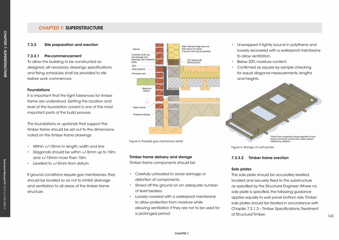
CHAPTER 7: SuPERSTRuCTuRECH
APTER 7: Su
PERSTRuC
TuRE
Tec
hn
ica
l Ma
nua
l V7: TS-011a
-7.00-180814
CHAPTER 7
143
7.3.3 site preparation and erection
7.3.3.1 Pre-commencementTo allow the building to be constructed as
designed, all necessary drawings, specifications
and fixing schedules shall be provided to site
before work commences.
foundationsIt is important that the tight tolerances for timber
frame are understood. Getting the location and
level of the foundation correct is one of the most
important parts of the build process.
The foundations or upstands that support the
timber frame should be set out to the dimensions
noted on the timber frame drawings:
• Within +/-10mm in length, width and line
• Diagonals should be within +/-5mm up to 10m,
and +/-10mm more than 10m
• Levelled to +/-5mm from datum
If ground conditions require gas membranes, they
should be located so as not to inhibit drainage
and ventilation to all areas of the timber frame
structure.
Figure 5: Possible gas membrane detail
Figure 6: Storage of wall panels
Timber frame delivery and storageTimber frame components should be:
• Carefully unloaded to avoid damage or
distortion of components.
• Stored off the ground on an adequate number
of level bearers.
• Loosely covered with a waterproof membrane
to allow protection from moisture while
allowing ventilation if they are not to be used for
a prolonged period.
• unwrapped if tightly bound in polythene and
loosely recovered with a waterproof membrane
to allow ventilation.
• Below 20% moisture content.
• Confirmed as square by sample checking
for equal diagonal measurements, lengths
and heights.
7.3.3.2 Timber frame erection
sole platesThe sole plate should be accurately levelled,
located and securely fixed to the substructure
as specified by the Structural Engineer. Where no
sole plate is specified, the following guidance
applies equally to wall panel bottom rails. Timber
sole plates should be treated in accordance with
Chapter 7.3.1.3 – Timber Specifications, Treatment
of Structural Timber.

CHAPTER 7: SuPERSTRuCTuRE CH
APTER 7: Su
PERSTRuC
TuRE
Tec
hn
ica
l Ma
nua
l V7: TS-011a
-7.00-180814
LocationSole plates should:
• Be located so that all structural timber is at least 150mm above external ground level (except for localised ramping at door openings). The use of a foundation kerb upstand may be an appropriate method to achieve this.• Be levelled to +/-5mm from datum.• Not overhang or be set back from the foundation edge by more than 10mm.• Be set out within +/-10mm in length and in line within +/-5mm, as defined by the timber frame drawings.• Diagonals should be within +/-5mm up to 10m, and +/-10mm for more than 10m.
Damp Proof Course (DPC)A DPC should:
• Be located directly below all timber sole plates bearing on other materials that may transfer moisture.• Overlap at DPC junctions by at least 100mm.• Be located flush to the outside edge of the sole plate.
PackingStructural shims or grout may be required under sole plates to level them and transfer vertical load. Longer sole plate to foundation fixings may be
needed to allow for the size of the gap.
Figure 7: Locating sole plates
Figure 8: kerb upstand detail to allow level threshold
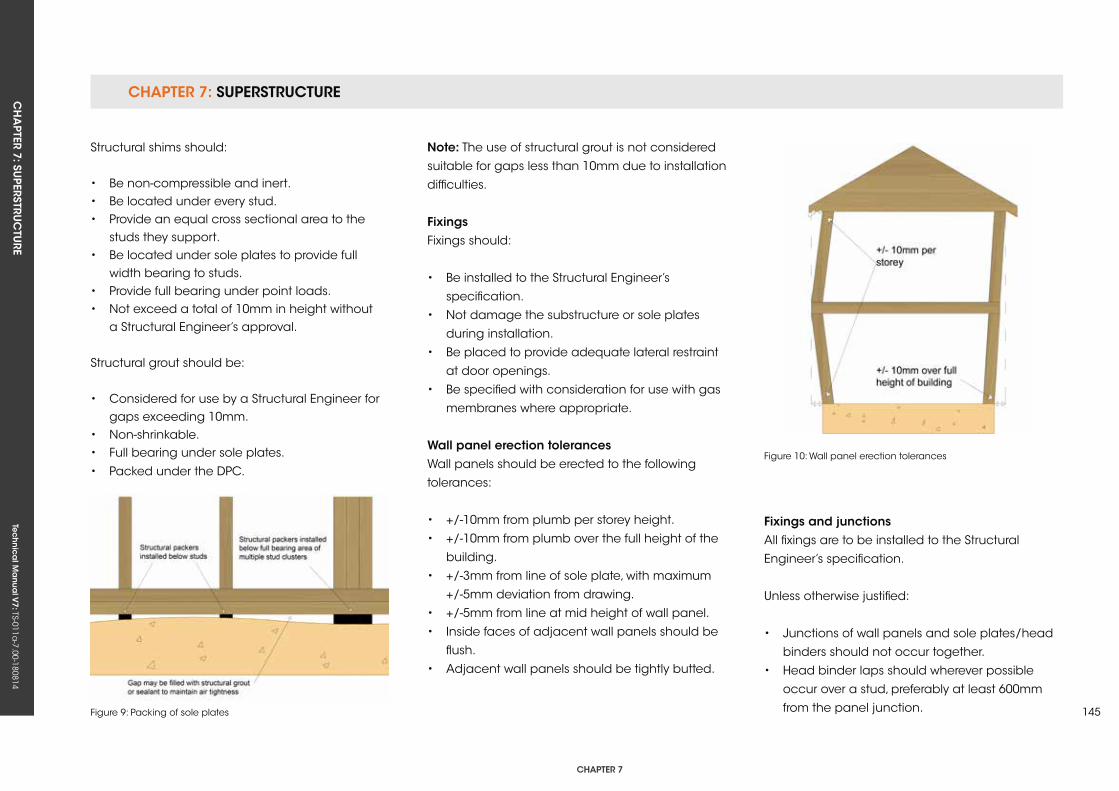
CHAPTER 7: SuPERSTRuCTuRECH
APTER 7: Su
PERSTRuC
TuRE
Tec
hn
ica
l Ma
nua
l V7: TS-011a
-7.00-180814
CHAPTER 7
145
Structural shims should:
• Be non-compressible and inert.• Be located under every stud.• Provide an equal cross sectional area to the studs they support.• Be located under sole plates to provide full width bearing to studs.• Provide full bearing under point loads.• Not exceed a total of 10mm in height without a Structural Engineer’s approval.
Structural grout should be:
• Considered for use by a Structural Engineer for gaps exceeding 10mm.• Non-shrinkable.• Full bearing under sole plates.
• Packed under the DPC.
Figure 9: Packing of sole plates
Figure 10: Wall panel erection tolerances
note: The use of structural grout is not considered
suitable for gaps less than 10mm due to installation
difficulties.
fixingsFixings should:
• Be installed to the Structural Engineer’s
specification.
• Not damage the substructure or sole plates
during installation.
• Be placed to provide adequate lateral restraint
at door openings.
• Be specified with consideration for use with gas
membranes where appropriate.
Wall panel erection tolerancesWall panels should be erected to the following
tolerances:
• +/-10mm from plumb per storey height.
• +/-10mm from plumb over the full height of the
building.
• +/-3mm from line of sole plate, with maximum
+/-5mm deviation from drawing.
• +/-5mm from line at mid height of wall panel.
• Inside faces of adjacent wall panels should be
flush.
• Adjacent wall panels should be tightly butted.
fixings and junctionsAll fixings are to be installed to the Structural
Engineer’s specification.
unless otherwise justified:
• Junctions of wall panels and sole plates/head
binders should not occur together.
• Head binder laps should wherever possible
occur over a stud, preferably at least 600mm
from the panel junction.

CHAPTER 7: SuPERSTRuCTuRE CH
APTER 7: Su
PERSTRuC
TuRE
Tec
hn
ica
l Ma
nua
l V7: TS-011a
-7.00-180814
• Wall panel to wall panel connections should be
a maximum of 300mm centres.
• Bottom rail to sole plate fixings should be one or
two per stud bay.
• Wall panels should be adequately braced
during erection to maintain tolerances.
• Disproportionate collapse fitting and fixings
must be installed if specified.
• Multiple stud clusters must be installed to the full
width of point load bearings.
• Point loads must be transferred down through
wall panels and floor zones to foundations.
• Closed panel walls manufactured off-site must
be fixed together as specified.
• Closed panel walls should not be exposed for
longer than necessary to avoid moisture ingress.
• Engineered timber components should not be
exposed to moisture for longer periods than
those stated by the manufacturer.
• Roof trusses/rafters should be adequately fixed
to wall panels.
• Floor joists should be nailed down to wall
panels.
• If no head binder is present, floor joists must
bear directly over studs.
• Waistbands and alignment of floors over walls
should remain within tolerances for wall panels.
Air leakageDetailing and installation instructions must be
followed to achieve adequate air tightness.
Figure 11: Head binder lapping Figure 12: Typical floor zone air tightness detail
Breather membraneBreather membrane should be:
• Lapped to deflect moisture away from the
timber frame structure.
• Lapped by a minimum of 100mm at horizontal
joints and a minimum of 150mm at vertical joints.
• Trimmed to leave a 25mm lap below the lowest
timber sole plate.
• Repaired if damaged.
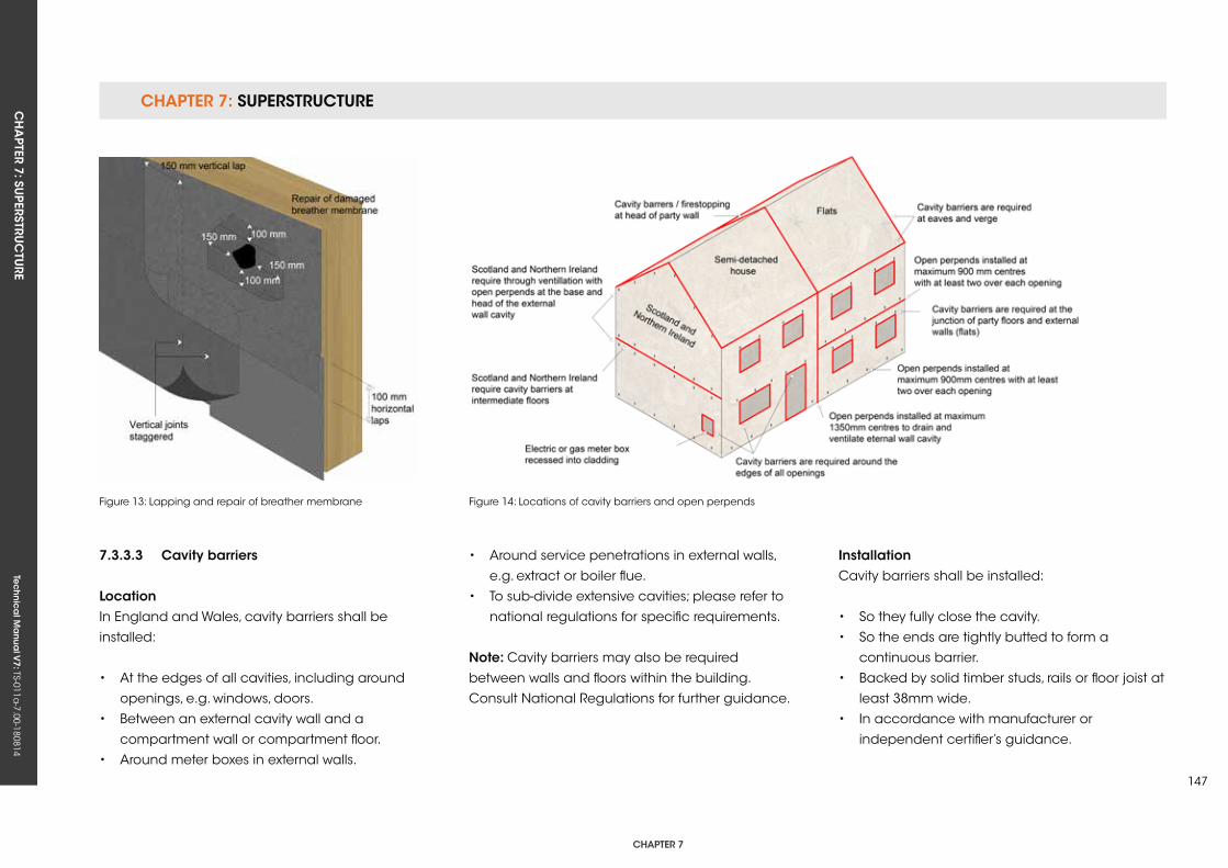
CHAPTER 7: SuPERSTRuCTuRECH
APTER 7: Su
PERSTRuC
TuRE
Tec
hn
ica
l Ma
nua
l V7: TS-011a
-7.00-180814
CHAPTER 7
147
7.3.3.3 Cavity barriers
LocationIn England and Wales, cavity barriers shall be
installed:
• At the edges of all cavities, including around
openings, e.g. windows, doors.
• Between an external cavity wall and a
compartment wall or compartment floor.
• Around meter boxes in external walls.
Figure 13: Lapping and repair of breather membrane Figure 14: Locations of cavity barriers and open perpends
• Around service penetrations in external walls,
e.g. extract or boiler flue.
• To sub-divide extensive cavities; please refer to
national regulations for specific requirements.
note: Cavity barriers may also be required
between walls and floors within the building.
Consult National Regulations for further guidance.
installationCavity barriers shall be installed:
• So they fully close the cavity.
• So the ends are tightly butted to form a
continuous barrier.
• Backed by solid timber studs, rails or floor joist at
least 38mm wide.
• In accordance with manufacturer or
independent certifier’s guidance.
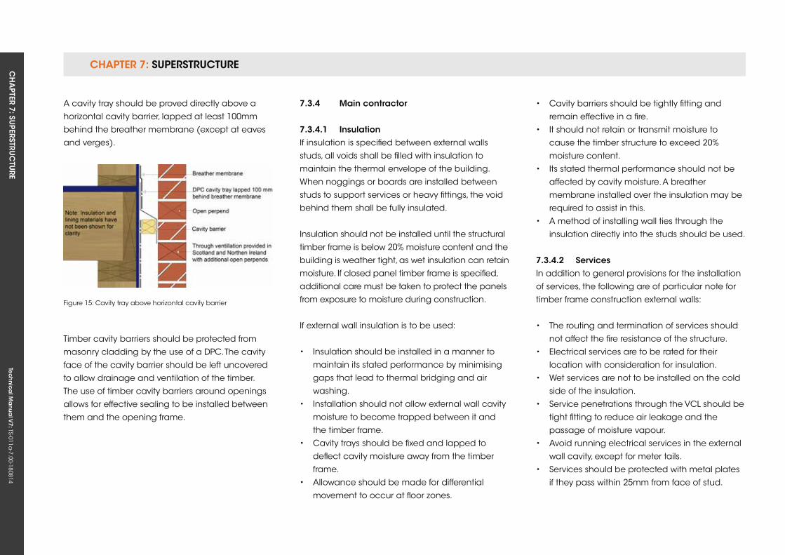
CHAPTER 7: SuPERSTRuCTuRE CH
APTER 7: Su
PERSTRuC
TuRE
Tec
hn
ica
l Ma
nua
l V7: TS-011a
-7.00-180814
A cavity tray should be proved directly above a
horizontal cavity barrier, lapped at least 100mm
behind the breather membrane (except at eaves
and verges).
Figure 15: Cavity tray above horizontal cavity barrier
Timber cavity barriers should be protected from
masonry cladding by the use of a DPC. The cavity
face of the cavity barrier should be left uncovered
to allow drainage and ventilation of the timber.
The use of timber cavity barriers around openings
allows for effective sealing to be installed between
them and the opening frame.
7.3.4 Main contractor
7.3.4.1 insulationIf insulation is specified between external walls
studs, all voids shall be filled with insulation to
maintain the thermal envelope of the building.
When noggings or boards are installed between
studs to support services or heavy fittings, the void
behind them shall be fully insulated.
Insulation should not be installed until the structural
timber frame is below 20% moisture content and the
building is weather tight, as wet insulation can retain
moisture. If closed panel timber frame is specified,
additional care must be taken to protect the panels
from exposure to moisture during construction.
If external wall insulation is to be used:
• Insulation should be installed in a manner to
maintain its stated performance by minimising
gaps that lead to thermal bridging and air
washing.
• Installation should not allow external wall cavity
moisture to become trapped between it and
the timber frame.
• Cavity trays should be fixed and lapped to
deflect cavity moisture away from the timber
frame.
• Allowance should be made for differential
movement to occur at floor zones.
• Cavity barriers should be tightly fitting and
remain effective in a fire.
• It should not retain or transmit moisture to
cause the timber structure to exceed 20%
moisture content.
• Its stated thermal performance should not be
affected by cavity moisture. A breather
membrane installed over the insulation may be
required to assist in this.
• A method of installing wall ties through the
insulation directly into the studs should be used.
7.3.4.2 servicesIn addition to general provisions for the installation
of services, the following are of particular note for
timber frame construction external walls:
• The routing and termination of services should
not affect the fire resistance of the structure.
• Electrical services are to be rated for their
location with consideration for insulation.
• Wet services are not to be installed on the cold
side of the insulation.
• Service penetrations through the VCL should be
tight fitting to reduce air leakage and the
passage of moisture vapour.
• Avoid running electrical services in the external
wall cavity, except for meter tails.
• Services should be protected with metal plates
if they pass within 25mm from face of stud.
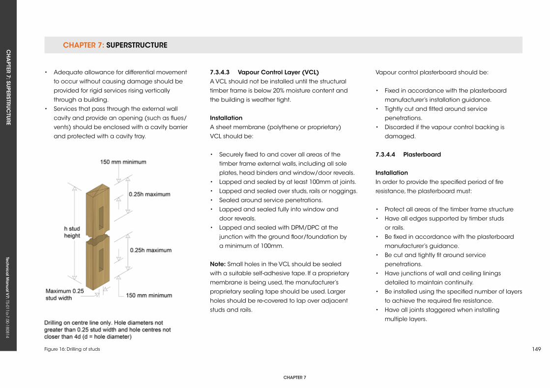
CHAPTER 7: SuPERSTRuCTuRECH
APTER 7: Su
PERSTRuC
TuRE
Tec
hn
ica
l Ma
nua
l V7: TS-011a
-7.00-180814
CHAPTER 7
149Figure 16: Drilling of studs
• Adequate allowance for differential movement
to occur without causing damage should be
provided for rigid services rising vertically
through a building.
• Services that pass through the external wall
cavity and provide an opening (such as flues/
vents) should be enclosed with a cavity barrier
and protected with a cavity tray.
7.3.4.3 vapour Control Layer (vCL)A VCL should not be installed until the structural
timber frame is below 20% moisture content and
the building is weather tight.
installationA sheet membrane (polythene or proprietary)
VCL should be:
• Securely fixed to and cover all areas of the
timber frame external walls, including all sole
plates, head binders and window/door reveals.
• Lapped and sealed by at least 100mm at joints.
• Lapped and sealed over studs, rails or noggings.
• Sealed around service penetrations.
• Lapped and sealed fully into window and
door reveals.
• Lapped and sealed with DPM/DPC at the
junction with the ground floor/foundation by
a minimum of 100mm.
note: Small holes in the VCL should be sealed
with a suitable self-adhesive tape. If a proprietary
membrane is being used, the manufacturer’s
proprietary sealing tape should be used. Larger
holes should be re-covered to lap over adjacent
studs and rails.
Vapour control plasterboard should be:
• Fixed in accordance with the plasterboard
manufacturer’s installation guidance.
• Tightly cut and fitted around service
penetrations.
• Discarded if the vapour control backing is
damaged.
7.3.4.4 Plasterboard
installationIn order to provide the specified period of fire
resistance, the plasterboard must:
• Protect all areas of the timber frame structure
• Have all edges supported by timber studs
or rails.
• Be fixed in accordance with the plasterboard
manufacturer’s guidance.
• Be cut and tightly fit around service
penetrations.
• Have junctions of wall and ceiling linings
detailed to maintain continuity.
• Be installed using the specified number of layers
to achieve the required fire resistance.
• Have all joints staggered when installing
multiple layers.
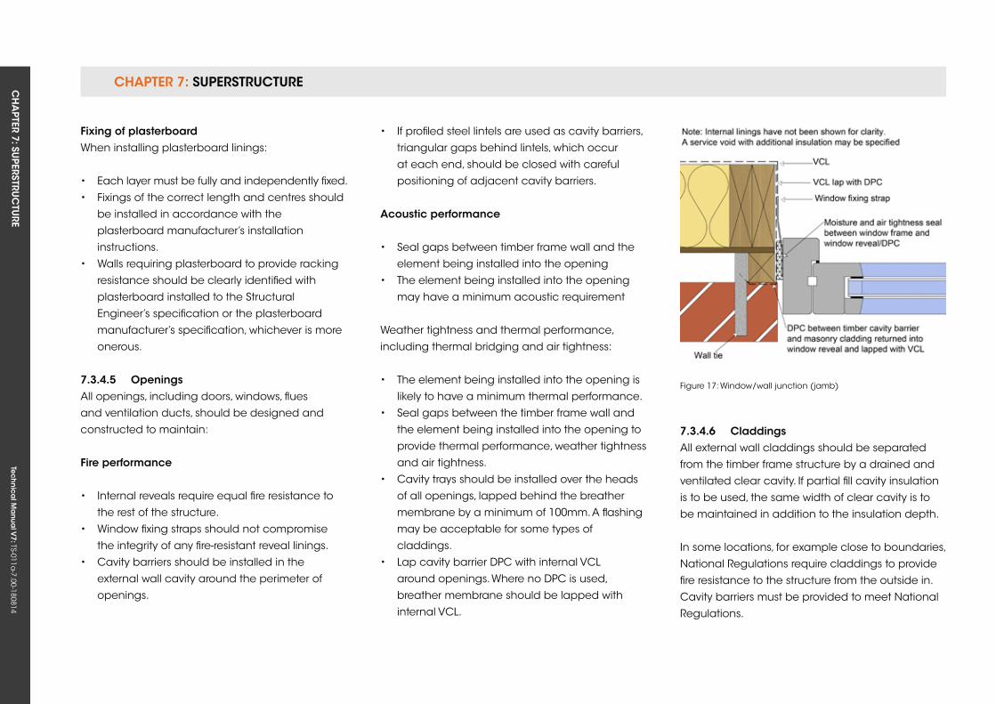
CHAPTER 7: SuPERSTRuCTuRE CH
APTER 7: Su
PERSTRuC
TuRE
Tec
hn
ica
l Ma
nua
l V7: TS-011a
-7.00-180814
fixing of plasterboardWhen installing plasterboard linings:
• Each layer must be fully and independently fixed.
• Fixings of the correct length and centres should
be installed in accordance with the
plasterboard manufacturer’s installation
instructions.
• Walls requiring plasterboard to provide racking
resistance should be clearly identified with
plasterboard installed to the Structural
Engineer’s specification or the plasterboard
manufacturer’s specification, whichever is more
onerous.
7.3.4.5 openingsAll openings, including doors, windows, flues
and ventilation ducts, should be designed and
constructed to maintain:
fire performance
• Internal reveals require equal fire resistance to
the rest of the structure.
• Window fixing straps should not compromise
the integrity of any fire-resistant reveal linings.
• Cavity barriers should be installed in the
external wall cavity around the perimeter of
openings.
Figure 17: Window/wall junction (jamb)
• If profiled steel lintels are used as cavity barriers,
triangular gaps behind lintels, which occur
at each end, should be closed with careful
positioning of adjacent cavity barriers.
Acoustic performance
• Seal gaps between timber frame wall and the
element being installed into the opening
• The element being installed into the opening
may have a minimum acoustic requirement
Weather tightness and thermal performance,
including thermal bridging and air tightness:
• The element being installed into the opening is
likely to have a minimum thermal performance.
• Seal gaps between the timber frame wall and
the element being installed into the opening to
provide thermal performance, weather tightness
and air tightness.
• Cavity trays should be installed over the heads
of all openings, lapped behind the breather
membrane by a minimum of 100mm. A flashing
may be acceptable for some types of
claddings.
• Lap cavity barrier DPC with internal VCL
around openings. Where no DPC is used,
breather membrane should be lapped with
internal VCL.
7.3.4.6 CladdingsAll external wall claddings should be separated
from the timber frame structure by a drained and
ventilated clear cavity. If partial fill cavity insulation
is to be used, the same width of clear cavity is to
be maintained in addition to the insulation depth.
In some locations, for example close to boundaries,
National Regulations require claddings to provide
fire resistance to the structure from the outside in.
Cavity barriers must be provided to meet National
Regulations.
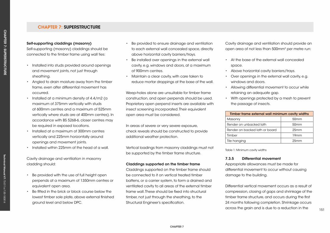
CHAPTER 7: SuPERSTRuCTuRECH
APTER 7: Su
PERSTRuC
TuRE
Tec
hn
ica
l Ma
nua
l V7: TS-011a
-7.00-180814
CHAPTER 7
151
self-supporting claddings (masonry)Self-supporting (masonry) claddings should be
connected to the timber frame using wall ties:
• Installed into studs provided around openings
and movement joints, not just through
sheathing.
• Angled to drain moisture away from the timber
frame, even after differential movement has
occurred.
• Installed at a minimum density of 4.4/m2 (a
maximum of 375mm vertically with studs
at 600mm centres and a maximum of 525mm
vertically where studs are at 400mm centres). In
accordance with BS 5268-6, closer centres may
be required in exposed locations.
• Installed at a maximum of 300mm centres
vertically and 225mm horizontally around
openings and movement joints.
• Installed within 225mm of the head of a wall.
Cavity drainage and ventilation in masonry
cladding should:
• Be provided with the use of full height open
perpends at a maximum of 1350mm centres or
equivalent open area.
• Be fitted in the brick or block course below the
lowest timber sole plate, above external finished
ground level and below DPC.
• Be provided to ensure drainage and ventilation
to each external wall concealed space, directly
above horizontal cavity barriers/trays.
• Be installed over openings in the external wall
cavity, e.g. windows and doors, at a maximum
of 900mm centres.
• Maintain a clear cavity, with care taken to
reduce mortar droppings at the base of the wall.
Weep-holes alone are unsuitable for timber frame
construction, and open perpends should be used.
Proprietary open perpend inserts are available with
insect screening incorporated. Their equivalent
open area must be considered.
In areas of severe or very severe exposure,
check reveals should be constructed to provide
additional weather protection.
Vertical loadings from masonry claddings must not
be supported by the timber frame structure.
Claddings supported on the timber frame Claddings supported on the timber frame should
be connected to it on vertical treated timber
battens, or a carrier system, to form a drained and
ventilated cavity to all areas of the external timber
frame wall. These should be fixed into structural
timber, not just through the sheathing, to the
Structural Engineer’s specification.
Timber frame external wall minimum cavity widths
Masonry 50mm
Render on unbacked lath 50mm
Render on backed lath or board 25mm
Timber 19mm
Tile hanging 25mm
Table 1: Minimum cavity widths
Cavity drainage and ventilation should provide an
open area of not less than 500mm2 per metre run:
• At the base of the external wall concealed
space.
• Above horizontal cavity barriers/trays.
• Over openings in the external wall cavity, e.g.
windows and doors.
• Allowing differential movement to occur while
retaining an adequate gap.
• With openings protected by a mesh to prevent
the passage of insects.
7.3.5 Differential movementAppropriate allowances must be made for
differential movement to occur without causing
damage to the building.
Differential vertical movement occurs as a result of
compression, closing of gaps and shrinkage of the
timber frame structure, and occurs during the first
24 months following completion. Shrinkage occurs
across the grain and is due to a reduction in the
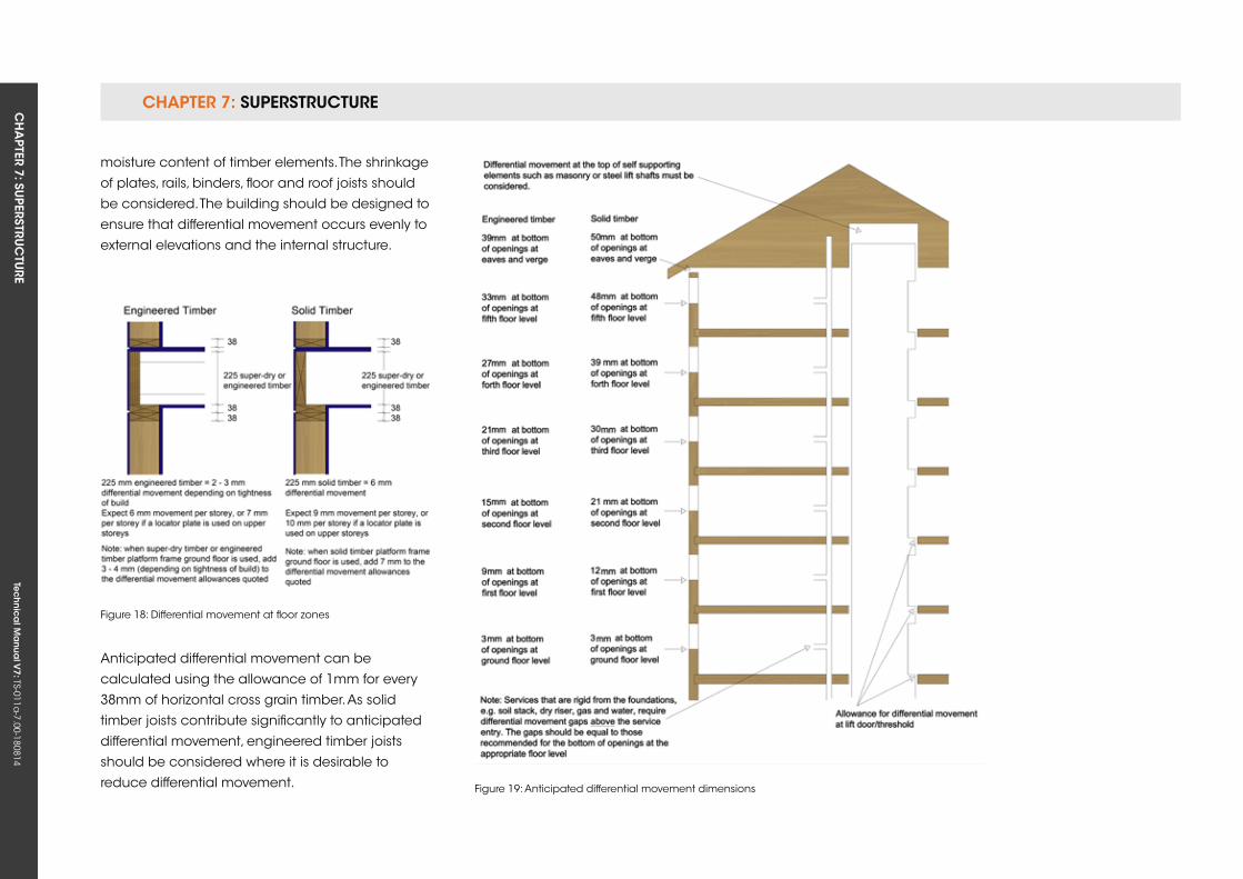
CHAPTER 7: SuPERSTRuCTuRE CH
APTER 7: Su
PERSTRuC
TuRE
Tec
hn
ica
l Ma
nua
l V7: TS-011a
-7.00-180814
Figure 18: Differential movement at floor zones
Figure 19: Anticipated differential movement dimensions
moisture content of timber elements. The shrinkage
of plates, rails, binders, floor and roof joists should
be considered. The building should be designed to
ensure that differential movement occurs evenly to
external elevations and the internal structure.
Anticipated differential movement can be
calculated using the allowance of 1mm for every
38mm of horizontal cross grain timber. As solid
timber joists contribute significantly to anticipated
differential movement, engineered timber joists
should be considered where it is desirable to
reduce differential movement.
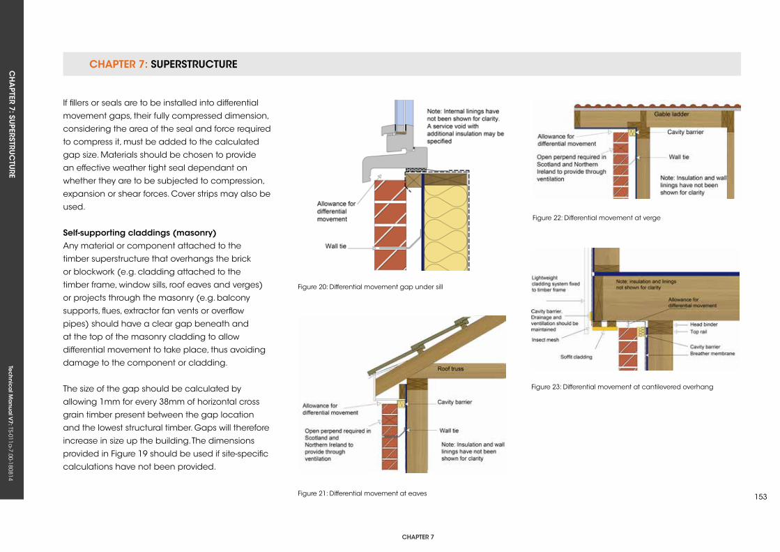
CHAPTER 7: SuPERSTRuCTuRECH
APTER 7: Su
PERSTRuC
TuRE
Tec
hn
ica
l Ma
nua
l V7: TS-011a
-7.00-180814
CHAPTER 7
153
Figure 20: Differential movement gap under sill
Figure 22: Differential movement at verge
Figure 21: Differential movement at eaves
Figure 23: Differential movement at cantilevered overhang
If fillers or seals are to be installed into differential
movement gaps, their fully compressed dimension,
considering the area of the seal and force required
to compress it, must be added to the calculated
gap size. Materials should be chosen to provide
an effective weather tight seal dependant on
whether they are to be subjected to compression,
expansion or shear forces. Cover strips may also be
used.
self-supporting claddings (masonry)Any material or component attached to the
timber superstructure that overhangs the brick
or blockwork (e.g. cladding attached to the
timber frame, window sills, roof eaves and verges)
or projects through the masonry (e.g. balcony
supports, flues, extractor fan vents or overflow
pipes) should have a clear gap beneath and
at the top of the masonry cladding to allow
differential movement to take place, thus avoiding
damage to the component or cladding.
The size of the gap should be calculated by
allowing 1mm for every 38mm of horizontal cross
grain timber present between the gap location
and the lowest structural timber. Gaps will therefore
increase in size up the building. The dimensions
provided in Figure 19 should be used if site-specific
calculations have not been provided.
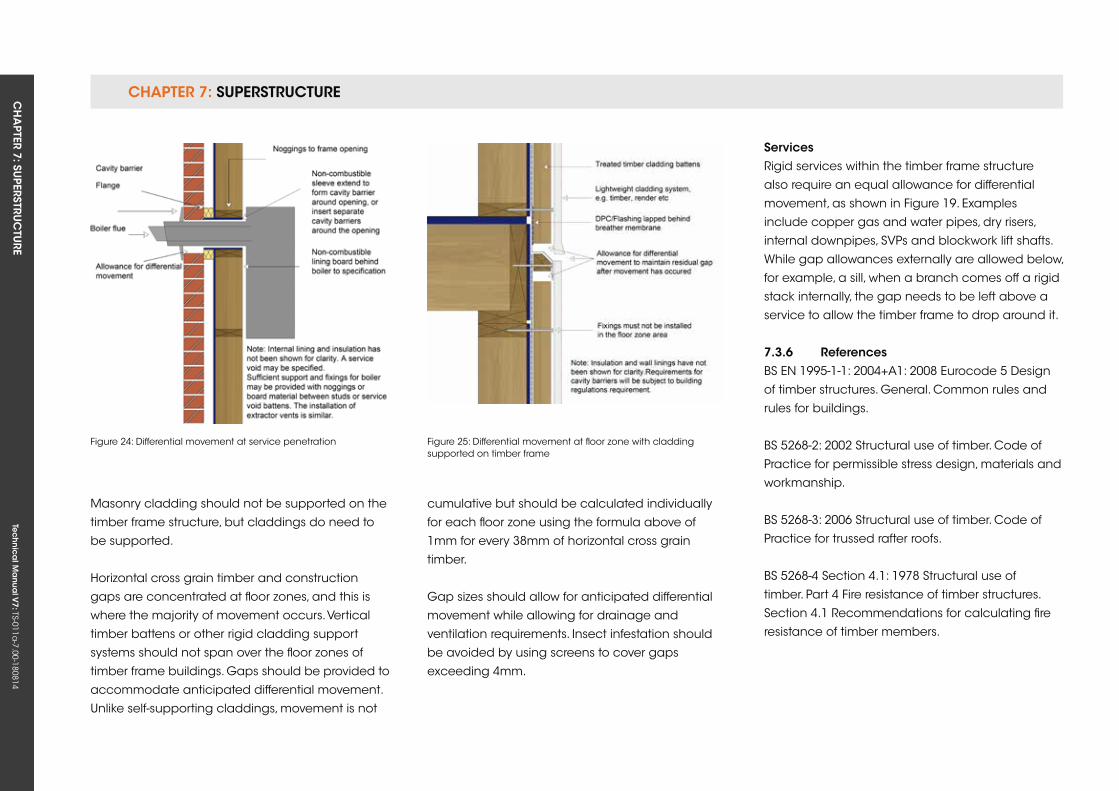
CHAPTER 7: SuPERSTRuCTuRE CH
APTER 7: Su
PERSTRuC
TuRE
Tec
hn
ica
l Ma
nua
l V7: TS-011a
-7.00-180814
Figure 24: Differential movement at service penetration Figure 25: Differential movement at floor zone with cladding supported on timber frame
Masonry cladding should not be supported on the
timber frame structure, but claddings do need to
be supported.
Horizontal cross grain timber and construction
gaps are concentrated at floor zones, and this is
where the majority of movement occurs. Vertical
timber battens or other rigid cladding support
systems should not span over the floor zones of
timber frame buildings. Gaps should be provided to
accommodate anticipated differential movement.
unlike self-supporting claddings, movement is not
cumulative but should be calculated individually
for each floor zone using the formula above of
1mm for every 38mm of horizontal cross grain
timber.
Gap sizes should allow for anticipated differential
movement while allowing for drainage and
ventilation requirements. Insect infestation should
be avoided by using screens to cover gaps
exceeding 4mm.
servicesRigid services within the timber frame structure
also require an equal allowance for differential
movement, as shown in Figure 19. Examples
include copper gas and water pipes, dry risers,
internal downpipes, SVPs and blockwork lift shafts.
While gap allowances externally are allowed below,
for example, a sill, when a branch comes off a rigid
stack internally, the gap needs to be left above a
service to allow the timber frame to drop around it.
7.3.6 referencesBS EN 1995-1-1: 2004+A1: 2008 Eurocode 5 Design
of timber structures. General. Common rules and
rules for buildings.
BS 5268-2: 2002 Structural use of timber. Code of
Practice for permissible stress design, materials and
workmanship.
BS 5268-3: 2006 Structural use of timber. Code of
Practice for trussed rafter roofs.
BS 5268-4 Section 4.1: 1978 Structural use of
timber. Part 4 Fire resistance of timber structures.
Section 4.1 Recommendations for calculating fire
resistance of timber members.
CHAPTER 7: SuPERSTRuCTuRECH
APTER 7: Su
PERSTRuC
TuRE
Tec
hn
ica
l Ma
nua
l V7: TS-011a
-7.00-180814
CHAPTER 7
155
BS 5268-4 Section 4.2: 1990 Structural use of
timber. Part 4 Fire resistance of timber structures.
Section 4.2 Recommendations for calculating fire
resistance of timber stud walls and joisted floor
constructions.
BS 5268-6.1: 1996 Structural use of timber. Code
of Practice for timber frame walls. Dwellings not
exceeding seven storeys.
BS 5268-6.2: 2001 Structural use of timber. Code of
Practice for timber frame walls. Buildings other than
dwellings not exceeding four storeys.
BS EN 14081-1: 2005 Timber structures. Strength
graded structural timber with rectangular cross
section. General requirements.
BS 8417: 2003 Preservation of timber.
Recommendations.
BS EN 13986: 2006 Wood-based panels for use
in construction. Characteristics, evaluation of
conformity and marking.
BS EN 300: 2006 Oriented strand boards (OSB).
Definitions, classification and specifications.
BS EN 636: 2003 Plywood. Specifications.
BS EN 622-4: 2009 Fibreboards – Specifications.
Requirements for softboards.
BS EN 622-3: 2004 Fibreboards – Specifications.
Requirements for medium boards.
BS EN 622-2: 2004 Fibreboards – Specifications.
Requirements for hardboards.
BS 4016: 1997 Specification for flexible building
membranes (breather type).
BS EN 845-1: 2003+A1: 2008 Specification for
ancillary components for masonry. Ties, tension
straps, hangers and brackets.
EN 14732: 2011 Timber structures. Prefabricated wall,
floor and roof elements. Requirements Draft
for comment.
Tec
hn
ica
l Ma
nua
l V6: TS-011a
-6.00-010413Te
ch
nic
al M
anu
al V
7: TS-011a-7.00-180814
FUNCTIONAL REQUIREMENTS
Workmanshipi. All workmanship must be within the tolerances defined in Chapter 1
of this Manual.
ii. All work is to be carried out by a technically competent person in
a workmanlike manner.
iii. Certification is required for any work completed by an approved
installer.
Materialsi. All materials should be stored correctly in a manner that will not cause
damage or deterioration of the product.
ii. All materials, products and building systems shall be appropriate and
suitable for their intended purpose.
iii. The structure shall, unless specifically agreed otherwise with the
Warranty provider, have a life of not less than 60 years. Individual
components and assemblies, not integral to the structure, may have
a lesser durability, but not in any circumstances less than 15 years.
Designi. The design and specifications shall provide a clear indication of the
design intent and demonstrate a satisfactory level of performance.
ii. Structural elements outside the parameters of regional Approved
Documents must be supported by structural calculations provided by
a suitably qualified expert.
iii. The materials, design and construction must meet the relevant
Building Regulations, British Standards, Eurocodes and other statutory
requirements.
7.4 WinDoWs AnD Doors
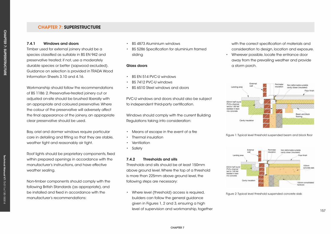
CHAPTER 7: SuPERSTRuCTuRECH
APTER 7: Su
PERSTRuC
TuRE
Tec
hn
ica
l Ma
nua
l V7: TS-011a
-7.00-180814
CHAPTER 7
157
7.4.1 Windows and doors Timber used for external joinery should be a
species classified as suitable in BS EN 942 and
preservative treated; if not, use a moderately
durable species or better (sapwood excluded).
Guidance on selection is provided in TRADA Wood
Information Sheets 3.10 and 4.16.
Workmanship should follow the recommendations
of BS 1186: 2. Preservative-treated joinery cut or
adjusted on-site should be brushed liberally with
an appropriate and coloured preservative. Where
the colour of the preservative will adversely affect
the final appearance of the joinery, an appropriate
clear preservative should be used.
Bay, oriel and dormer windows require particular
care in detailing and fitting so that they are stable,
weather tight and reasonably air tight.
Roof lights should be proprietary components, fixed
within prepared openings in accordance with the
manufacturer’s instructions, and have effective
weather sealing.
Non-timber components should comply with the
following British Standards (as appropriate), and
be installed and fixed in accordance with the
manufacturer’s recommendations:
• BS 4873 Aluminium windows
• BS 5286 Specification for aluminium framed
sliding
glass doors
• BS EN 514 PVC-u windows
• BS 7412 PVC-u windows
• BS 6510 Steel windows and doors
PVC-u windows and doors should also be subject
to independent third-party certification.
Windows should comply with the current Building
Regulations taking into consideration:
• Means of escape in the event of a fire
• Thermal insulation
• Ventilation
• Safety
7.4.2 Thresholds and sillsThresholds and sills should be at least 150mm
above ground level. Where the top of a threshold
is more than 225mm above ground level, the
following steps are necessary:
• Where level (threshold) access is required,
builders can follow the general guidance
given in Figures 1, 2 and 3, ensuring a high
level of supervision and workmanship, together
with the correct specification of materials and
consideration to design, location and exposure.
• Wherever possible, locate the entrance door
away from the prevailing weather and provide
a storm porch.
Figure 1: Typical level threshold suspended beam and block floor
Figure 2: Typical level threshold suspended concrete slab
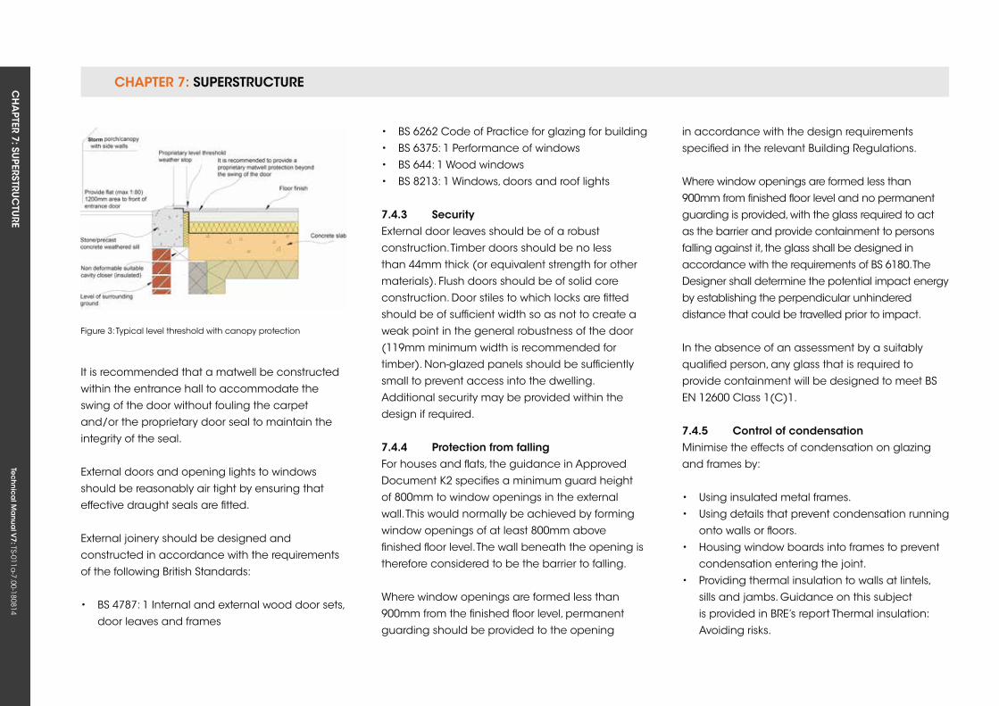
CHAPTER 7: SuPERSTRuCTuRE CH
APTER 7: Su
PERSTRuC
TuRE
Tec
hn
ica
l Ma
nua
l V7: TS-011a
-7.00-180814
It is recommended that a matwell be constructed
within the entrance hall to accommodate the
swing of the door without fouling the carpet
and/or the proprietary door seal to maintain the
integrity of the seal.
External doors and opening lights to windows
should be reasonably air tight by ensuring that
effective draught seals are fitted.
External joinery should be designed and
constructed in accordance with the requirements
of the following British Standards:
• BS 4787: 1 Internal and external wood door sets,
door leaves and frames
Figure 3: Typical level threshold with canopy protection
• BS 6262 Code of Practice for glazing for building
• BS 6375: 1 Performance of windows
• BS 644: 1 Wood windows
• BS 8213: 1 Windows, doors and roof lights
7.4.3 securityExternal door leaves should be of a robust
construction. Timber doors should be no less
than 44mm thick (or equivalent strength for other
materials). Flush doors should be of solid core
construction. Door stiles to which locks are fitted
should be of sufficient width so as not to create a
weak point in the general robustness of the door
(119mm minimum width is recommended for
timber). Non-glazed panels should be sufficiently
small to prevent access into the dwelling.
Additional security may be provided within the
design if required.
7.4.4 Protection from fallingFor houses and flats, the guidance in Approved
Document k2 specifies a minimum guard height
of 800mm to window openings in the external
wall. This would normally be achieved by forming
window openings of at least 800mm above
finished floor level. The wall beneath the opening is
therefore considered to be the barrier to falling.
Where window openings are formed less than
900mm from the finished floor level, permanent
guarding should be provided to the opening
in accordance with the design requirements
specified in the relevant Building Regulations.
Where window openings are formed less than
900mm from finished floor level and no permanent
guarding is provided, with the glass required to act
as the barrier and provide containment to persons
falling against it, the glass shall be designed in
accordance with the requirements of BS 6180. The
Designer shall determine the potential impact energy
by establishing the perpendicular unhindered
distance that could be travelled prior to impact.
In the absence of an assessment by a suitably
qualified person, any glass that is required to
provide containment will be designed to meet BS
EN 12600 Class 1(C)1.
7.4.5 Control of condensationMinimise the effects of condensation on glazing
and frames by:
• using insulated metal frames.
• using details that prevent condensation running
onto walls or floors.
• Housing window boards into frames to prevent
condensation entering the joint.
• Providing thermal insulation to walls at lintels,
sills and jambs. Guidance on this subject
is provided in BRE’s report Thermal insulation:
Avoiding risks.
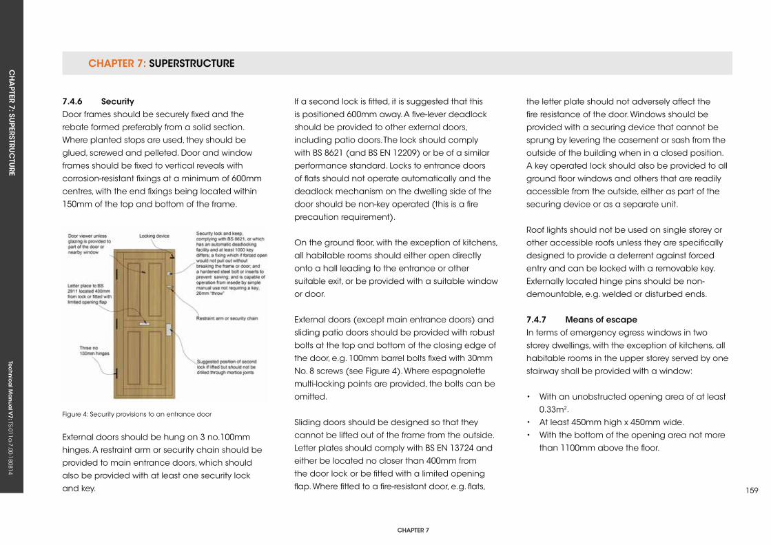
CHAPTER 7: SuPERSTRuCTuRECH
APTER 7: Su
PERSTRuC
TuRE
Tec
hn
ica
l Ma
nua
l V7: TS-011a
-7.00-180814
CHAPTER 7
159
7.4.6 securityDoor frames should be securely fixed and the
rebate formed preferably from a solid section.
Where planted stops are used, they should be
glued, screwed and pelleted. Door and window
frames should be fixed to vertical reveals with
corrosion-resistant fixings at a minimum of 600mm
centres, with the end fixings being located within
150mm of the top and bottom of the frame.
Figure 4: Security provisions to an entrance door
External doors should be hung on 3 no.100mm
hinges. A restraint arm or security chain should be
provided to main entrance doors, which should
also be provided with at least one security lock
and key.
If a second lock is fitted, it is suggested that this
is positioned 600mm away. A five-lever deadlock
should be provided to other external doors,
including patio doors. The lock should comply
with BS 8621 (and BS EN 12209) or be of a similar
performance standard. Locks to entrance doors
of flats should not operate automatically and the
deadlock mechanism on the dwelling side of the
door should be non-key operated (this is a fire
precaution requirement).
On the ground floor, with the exception of kitchens,
all habitable rooms should either open directly
onto a hall leading to the entrance or other
suitable exit, or be provided with a suitable window
or door.
External doors (except main entrance doors) and
sliding patio doors should be provided with robust
bolts at the top and bottom of the closing edge of
the door, e.g. 100mm barrel bolts fixed with 30mm
No. 8 screws (see Figure 4). Where espagnolette
multi-locking points are provided, the bolts can be
omitted.
Sliding doors should be designed so that they
cannot be lifted out of the frame from the outside.
Letter plates should comply with BS EN 13724 and
either be located no closer than 400mm from
the door lock or be fitted with a limited opening
flap. Where fitted to a fire-resistant door, e.g. flats,
the letter plate should not adversely affect the
fire resistance of the door. Windows should be
provided with a securing device that cannot be
sprung by levering the casement or sash from the
outside of the building when in a closed position.
A key operated lock should also be provided to all
ground floor windows and others that are readily
accessible from the outside, either as part of the
securing device or as a separate unit.
Roof lights should not be used on single storey or
other accessible roofs unless they are specifically
designed to provide a deterrent against forced
entry and can be locked with a removable key.
Externally located hinge pins should be non-
demountable, e.g. welded or disturbed ends.
7.4.7 Means of escapeIn terms of emergency egress windows in two
storey dwellings, with the exception of kitchens, all
habitable rooms in the upper storey served by one
stairway shall be provided with a window:
• With an unobstructed opening area of at least
0.33m2.
• At least 450mm high x 450mm wide.
• With the bottom of the opening area not more
than 1100mm above the floor.
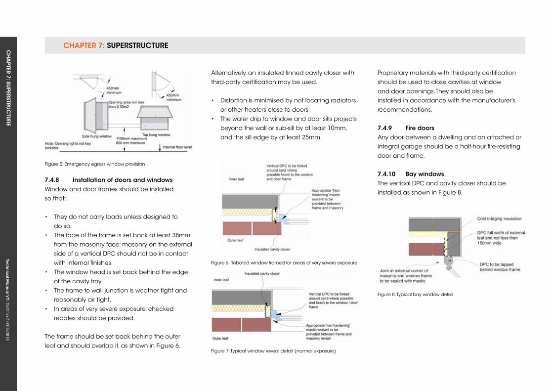
CHAPTER 7: SuPERSTRuCTuRE CH
APTER 7: Su
PERSTRuC
TuRE
Tec
hn
ica
l Ma
nua
l V7: TS-011a
-7.00-180814
7.4.8 installation of doors and windowsWindow and door frames should be installed
so that:
• They do not carry loads unless designed to
do so.
• The face of the frame is set back at least 38mm
from the masonry face; masonry on the external
side of a vertical DPC should not be in contact
with internal finishes.
• The window head is set back behind the edge
of the cavity tray.
• The frame to wall junction is weather tight and
reasonably air tight.
• In areas of very severe exposure, checked
rebates should be provided.
The frame should be set back behind the outer
leaf and should overlap it, as shown in Figure 6.
Figure 5: Emergency egress window provision
Figure 6: Rebated window framed for areas of very severe exposure
Figure 7: Typical window reveal detail (normal exposure)
Alternatively, an insulated finned cavity closer with
third-party certification may be used.
• Distortion is minimised by not locating radiators
or other heaters close to doors.
• The water drip to window and door sills projects
beyond the wall or sub-sill by at least 10mm,
and the sill edge by at least 25mm.
Figure 8: Typical bay window detail
Proprietary materials with third-party certification
should be used to close cavities at window
and door openings. They should also be
installed in accordance with the manufacturer’s
recommendations.
7.4.9 fire doorsAny door between a dwelling and an attached or
integral garage should be a half-hour fire-resisting
door and frame.
7.4.10 Bay windowsThe vertical DPC and cavity closer should be
installed as shown in Figure 8.
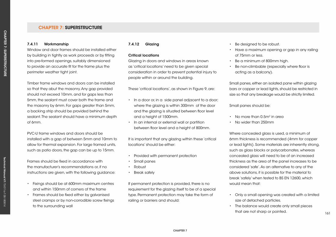
CHAPTER 7: SuPERSTRuCTuRECH
APTER 7: Su
PERSTRuC
TuRE
Tec
hn
ica
l Ma
nua
l V7: TS-011a
-7.00-180814
CHAPTER 7
161
7.4.11 WorkmanshipWindow and door frames should be installed either
by building in tightly as work proceeds or by fitting
into pre-formed openings, suitably dimensioned
to provide an accurate fit for the frame plus the
perimeter weather tight joint.
Timber frame windows and doors can be installed
so that they abut the masonry. Any gap provided
should not exceed 10mm, and for gaps less than
5mm, the sealant must cover both the frame and
the masonry by 6mm. For gaps greater than 5mm,
a backing strip should be provided behind the
sealant. The sealant should have a minimum depth
of 6mm.
PVC-u frame windows and doors should be
installed with a gap of between 5mm and 10mm to
allow for thermal expansion. For large framed units,
such as patio doors, the gap can be up to 15mm.
Frames should be fixed in accordance with
the manufacturer’s recommendations or, if no
instructions are given, with the following guidance:
• Fixings should be at 600mm maximum centres
and within 150mm of corners of the frame
• Frames should be fixed either by galvanised
steel cramps or by non-corrodible screw fixings
to the surrounding wall
7.4.12 glazing
Critical locationsGlazing in doors and windows in areas known
as ‘critical locations’ need to be given special
consideration in order to prevent potential injury to
people within or around the building.
These ‘critical locations’, as shown in Figure 9, are:
• In a door or, in a side panel adjacent to a door;
where the glazing is within 300mm of the door
and the glazing is situated between floor level
and a height of 1500mm.
• In an internal or external wall or partition
between floor level and a height of 800mm.
It is important that any glazing within these ‘critical
locations’ should be either:
• Provided with permanent protection
• Small panes
• Robust
• Break safely
If permanent protection is provided, there is no
requirement for the glazing itself to be of a special
type. Permanent protection may take the form of
railing or barriers and should:
• Be designed to be robust.
• Have a maximum opening or gap in any railing
of 75mm or less.
• Be a minimum of 800mm high.
• Be non-climbable (especially where floor is
acting as a balcony).
Small panes, either an isolated pane within glazing
bars or copper or lead lights, should be restricted in
size so that any breakage would be strictly limited.
Small panes should be:
• No more than 0.5m2 in area
• No wider than 250mm
Where concealed glass is used, a minimum of
6mm thickness is recommended (4mm for copper
or lead lights). Some materials are inherently strong,
such as glass blocks or polycarbonates, whereas
concealed glass will need to be of an increased
thickness as the area of the panel increases to be
considered ‘safe’. As an alternative to any of the
above solutions, it is possible for the material to
break ‘safely’ when tested to BS EN 12600, which
would mean that:
• Only a small opening was created with a limited
size of detached particles.
• The balance would create only small pieces
that are not sharp or pointed.
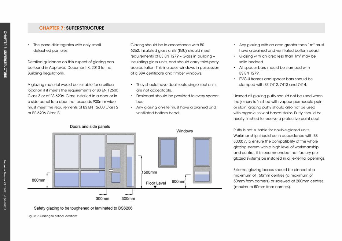
CHAPTER 7: SuPERSTRuCTuRE CH
APTER 7: Su
PERSTRuC
TuRE
Tec
hn
ica
l Ma
nua
l V7: TS-011a
-7.00-180814
Glazing should be in accordance with BS
6262. Insulated glass units (IGu) should meet
requirements of BS EN 1279 – Glass in building –
insulating glass units, and should carry third-party
accreditation. This includes windows in possession
of a BBA certificate and timber windows.
• They should have dual seals; single seal units
are not acceptable.
• Desiccant should be provided to every spacer
bar.
• Any glazing on-site must have a drained and
ventilated bottom bead.
• Any glazing with an area greater than 1m2 must
have a drained and ventilated bottom bead.
• Glazing with an area less than 1m2 may be
solid bedded.
• All spacer bars should be stamped with
BS EN 1279.
• PVC-u frames and spacer bars should be
stamped with BS 7412, 7413 and 7414.
Linseed oil glazing putty should not be used when
the joinery is finished with vapour permeable paint
or stain; glazing putty should also not be used
with organic solvent-based stains. Putty should be
neatly finished to receive a protective paint coat.
Putty is not suitable for double-glazed units.
Workmanship should be in accordance with BS
8000: 7. To ensure the compatibility of the whole
glazing system with a high level of workmanship
and control, it is recommended that factory pre-
glazed systems be installed in all external openings.
External glazing beads should be pinned at a
maximum of 150mm centres (a maximum of
50mm from corners) or screwed at 200mm centres
(maximum 50mm from corners).
Figure 9: Glazing to critical locations
• The pane disintegrates with only small
detached particles.
Detailed guidance on this aspect of glazing can
be found in Approved Document k: 2013 to the
Building Regulations.
A glazing material would be suitable for a critical
location if it meets the requirements of BS EN 12600
Class 3 or of BS 6206. Glass installed in a door or in
a side panel to a door that exceeds 900mm wide
must meet the requirements of BS EN 12600 Class 2
or BS 6206 Class B.
CHAPTER 7: SuPERSTRuCTuRECH
APTER 7: Su
PERSTRuC
TuRE
Tec
hn
ica
l Ma
nua
l V7: TS-011a
-7.00-180814
CHAPTER 7
163
The preferred method of installation for double-
glazed units is either:
• Drained and ventilated frames, as
recommended by the Glass and Glazing
Federation (GGF). Where possible, this method
should be adopted for external glazing.
• Solid bedding of units in 16mm–18mm deep frame
rebates; 18mm rebates are recommended
by the GGF to allow for tolerances. In all cases,
sealants should not be sensitive to ultraviolet
light. External glazing beads should be fixed at
a maximum of 150mm centres, and the glazing
bedded in non-setting putty. Louvre windows
should not be used. Double-glazing should be
fixed and bedded as recommended by the GGF.
Control of condensationMinimise the effects of condensation on glazing
and frames by:
• using insulated metal frames.
• using details that prevent condensation running
onto walls or floors.
• Housing window boards into frames to prevent
condensation entering the joint.
• Providing thermal insulation to walls at lintels,
sills and jambs.
• using trickle ventilators, or similar, to provide
background ventilation where required by the
Building Regulations. Further guidance on this
subject is provided in BRE report BR 262, Thermal
insulation: Avoiding risks 2002.
glazingGlass must meet the visual assessment criteria of
CWCT Technical Note 35 (TN 35). The total number
of faults permitted in a glass unit shall be the sum
total of those permitted by the relevant BS EN
Standard for each pane of glass incorporated into
the unit concerned.
Faults include:
• Bubbles or blisters
• Hairlines or blobs
• Fine scratches not more than 25mm long
• Minute particles
When assessing the appearance of glass:
• The viewing distance used shall be the furthest
stated in any of the BS EN Standards for the
glass types incorporated in the glazed unit. In
the event of doubt, the viewing distance shall
be three metres.
• The viewing shall commence at the viewing
distance, and shall not be preceded by viewing
at a closer distance.
• The viewing shall be undertaken in normal
daylight conditions without use of
magnification.
The above does not apply within 6mm of the edge
of the pane, where minor scratching is acceptable.
Scratches on doors, windows and frames and
factory finished door and window components
should not have conspicuous abrasions or
scratches when viewed from a distance of 0.5m.
• Surface abrasions caused during the building-
in process should be removed in accordance
with the manufacturer’s instructions, which may
include polishing out, re-spraying or painting.
• In rooms where there is no daylight, scratches
should be viewed in artificial light from fixed wall
or ceiling outlets, and not from portable
equipment.
Where window openings are formed less than
900mm from finished floor level and no permanent
guarding is provided, with the glass required
to act as the barrier and provide containment
to persons falling against it, the glass shall be
designed in accordance with the requirements of
BS 6180. The Designer shall determine the potential
impact energy by establishing the perpendicular
unhindered distance that could be travelled prior
to impact.
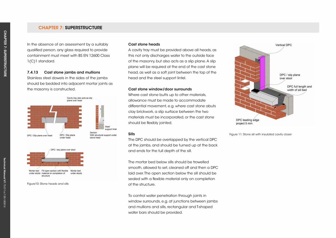
CHAPTER 7: SuPERSTRuCTuRE CH
APTER 7: Su
PERSTRuC
TuRE
Tec
hn
ica
l Ma
nua
l V7: TS-011a
-7.00-180814
In the absence of an assessment by a suitably
qualified person, any glass required to provide
containment must meet with BS EN 12600 Class
1(C)1 standard.
7.4.13 Cast stone jambs and mullionsStainless steel dowels in the sides of the jambs
should be bedded into adjacent mortar joints as
the masonry is constructed.
Figure10: Stone heads and sills
Figure 11: Stone sill with insulated cavity closer
Cast stone headsA cavity tray must be provided above all heads, as
this not only discharges water to the outside face
of the masonry, but also acts as a slip plane. A slip
plane will be required at the end of the cast stone
head, as well as a soft joint between the top of the
head and the steel support lintel.
Cast stone window/door surroundsWhere cast stone butts up to other materials,
allowance must be made to accommodate
differential movement, e.g. where cast stone abuts
clay brickwork, a slip surface between the two
materials must be incorporated, or the cast stone
should be flexibly jointed.
sillsThe DPC should be overlapped by the vertical DPC
at the jambs, and should be turned up at the back
and ends for the full depth of the sill.
The mortar bed below sills should be trowelled
smooth, allowed to set, cleaned off and then a DPC
laid over. The open section below the sill should be
sealed with a flexible material only on completion
of the structure.
To control water penetration through joints in
window surrounds, e.g. at junctions between jambs
and mullions and sills, rectangular and T-shaped
water bars should be provided.

Tec
hn
ica
l Ma
nua
l V6: TS-011a
-6.00-010413Te
ch
nic
al M
anu
al V
7: TS-011a-7.00-180814
FUNCTIONAL REQUIREMENTS
165
7.5 CHiMneys
Workmanshipi. All workmanship must be within the tolerances defined in Chapter 1
of this Manual.
ii. All work is to be carried out by a technically competent person in
a workmanlike manner.
iii. Certification is required for any work completed by an approved
installer.
Materialsi. All materials should be stored correctly in a manner that will not cause
damage or deterioration of the product.
ii. All materials, products and building systems shall be appropriate and
suitable for their intended purpose.
iii. The structure shall, unless specifically agreed otherwise with the
Warranty provider, have a life of not less than 60 years. Individual
components and assemblies, not integral to the structure, may have a
lesser durability, but not in any circumstances less than 15 years.
Designi. The design and specifications shall provide a clear indication of the
design intent and demonstrate a satisfactory level of performance.
ii. Structural elements outside the parameters of regional Approved
Documents must be supported by structural calculations provided by
a suitably qualified expert.
iii. The materials, design and construction must meet the relevant
Building Regulations, British Standards, Eurocodes and other statutory
requirements.
CHAPTer 7
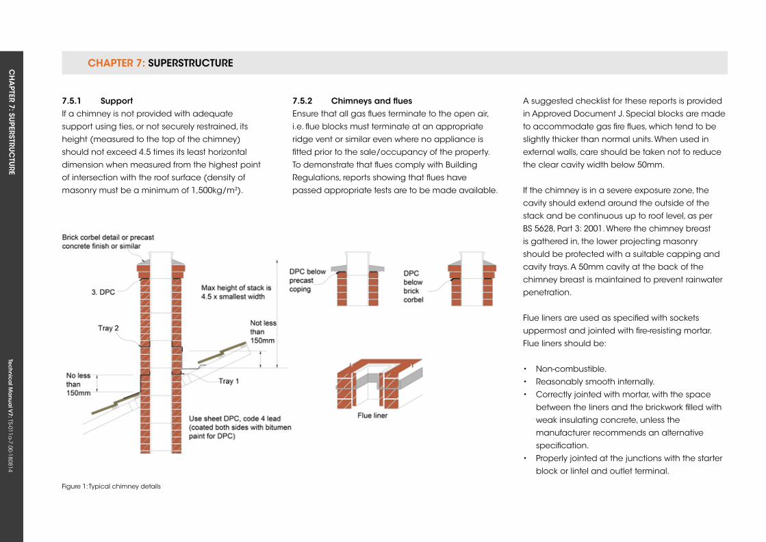
CHAPTER 7: SuPERSTRuCTuRE CH
APTER 7: Su
PERSTRuC
TuRE
Tec
hn
ica
l Ma
nua
l V7: TS-011a
-7.00-180814
7.5.1 supportIf a chimney is not provided with adequate
support using ties, or not securely restrained, its
height (measured to the top of the chimney)
should not exceed 4.5 times its least horizontal
dimension when measured from the highest point
of intersection with the roof surface (density of
masonry must be a minimum of 1,500kg/m3).
7.5.2 Chimneys and fluesEnsure that all gas flues terminate to the open air,
i.e. flue blocks must terminate at an appropriate
ridge vent or similar even where no appliance is
fitted prior to the sale/occupancy of the property.
To demonstrate that flues comply with Building
Regulations, reports showing that flues have
passed appropriate tests are to be made available.
Figure 1: Typical chimney details
A suggested checklist for these reports is provided
in Approved Document J. Special blocks are made
to accommodate gas fire flues, which tend to be
slightly thicker than normal units. When used in
external walls, care should be taken not to reduce
the clear cavity width below 50mm.
If the chimney is in a severe exposure zone, the
cavity should extend around the outside of the
stack and be continuous up to roof level, as per
BS 5628, Part 3: 2001. Where the chimney breast
is gathered in, the lower projecting masonry
should be protected with a suitable capping and
cavity trays. A 50mm cavity at the back of the
chimney breast is maintained to prevent rainwater
penetration.
Flue liners are used as specified with sockets
uppermost and jointed with fire-resisting mortar.
Flue liners should be:
• Non-combustible.
• Reasonably smooth internally.
• Correctly jointed with mortar, with the space
between the liners and the brickwork filled with
weak insulating concrete, unless the
manufacturer recommends an alternative
specification.
• Properly jointed at the junctions with the starter
block or lintel and outlet terminal.
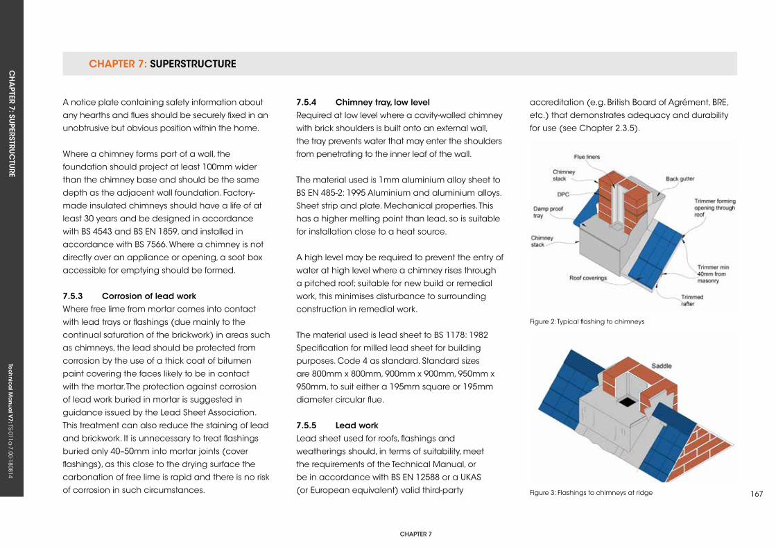
CHAPTER 7: SuPERSTRuCTuRECH
APTER 7: Su
PERSTRuC
TuRE
Tec
hn
ica
l Ma
nua
l V7: TS-011a
-7.00-180814
CHAPTER 7
167
A notice plate containing safety information about
any hearths and flues should be securely fixed in an
unobtrusive but obvious position within the home.
Where a chimney forms part of a wall, the
foundation should project at least 100mm wider
than the chimney base and should be the same
depth as the adjacent wall foundation. Factory-
made insulated chimneys should have a life of at
least 30 years and be designed in accordance
with BS 4543 and BS EN 1859, and installed in
accordance with BS 7566. Where a chimney is not
directly over an appliance or opening, a soot box
accessible for emptying should be formed.
7.5.3 Corrosion of lead workWhere free lime from mortar comes into contact
with lead trays or flashings (due mainly to the
continual saturation of the brickwork) in areas such
as chimneys, the lead should be protected from
corrosion by the use of a thick coat of bitumen
paint covering the faces likely to be in contact
with the mortar. The protection against corrosion
of lead work buried in mortar is suggested in
guidance issued by the Lead Sheet Association.
This treatment can also reduce the staining of lead
and brickwork. It is unnecessary to treat flashings
buried only 40–50mm into mortar joints (cover
flashings), as this close to the drying surface the
carbonation of free lime is rapid and there is no risk
of corrosion in such circumstances.
7.5.4 Chimney tray, low levelRequired at low level where a cavity-walled chimney
with brick shoulders is built onto an external wall,
the tray prevents water that may enter the shoulders
from penetrating to the inner leaf of the wall.
The material used is 1mm aluminium alloy sheet to
BS EN 485-2: 1995 Aluminium and aluminium alloys.
Sheet strip and plate. Mechanical properties. This
has a higher melting point than lead, so is suitable
for installation close to a heat source.
A high level may be required to prevent the entry of
water at high level where a chimney rises through
a pitched roof; suitable for new build or remedial
work, this minimises disturbance to surrounding
construction in remedial work.
The material used is lead sheet to BS 1178: 1982
Specification for milled lead sheet for building
purposes. Code 4 as standard. Standard sizes
are 800mm x 800mm, 900mm x 900mm, 950mm x
950mm, to suit either a 195mm square or 195mm
diameter circular flue.
7.5.5 Lead workLead sheet used for roofs, flashings and
weatherings should, in terms of suitability, meet
the requirements of the Technical Manual, or
be in accordance with BS EN 12588 or a ukAS
(or European equivalent) valid third-party
Figure 2: Typical flashing to chimneys
Figure 3: Flashings to chimneys at ridge
accreditation (e.g. British Board of Agrément, BRE,
etc.) that demonstrates adequacy and durability
for use (see Chapter 2.3.5).
Tec
hn
ica
l Ma
nua
l V6: TS-011a
-6.00-010413Te
ch
nic
al M
anu
al V
7: TS-011a-7.00-180814
FUNCTIONAL REQUIREMENTS
7.6 BALConies
Workmanshipi. All workmanship must be within the tolerances defined in Chapter 1
of this manual.
ii. All work is to be carried out by a technically competent person in
a workmanlike manner.
Materialsi. All materials should be stored correctly in a manner that will not cause
damage or deterioration of the product.
ii. All materials, products and building systems shall be appropriate and
suitable for their intended purpose.
iii. The structure shall, unless specifically agreed otherwise with the
Warranty provider, have a life of not less than 60 years. Individual
components and assemblies, not integral to the structure, may have
a lesser durability, but not in any circumstances less than 15 years.
Designi. The design and specifications shall provide a clear indication of the
design intent and demonstrate a satisfactory level of performance.
ii. Structural elements outside the parameters of regional Approved
Documents must be supported by structural calculations provided by
a suitably qualified expert.
iii. Balconies must have appropriate guarding meeting the relevant
Building Regulations.
iv. The balcony design and construction must meet the relevant
Building Regulations, British Standards, Eurocodes and other statutory
requirements.
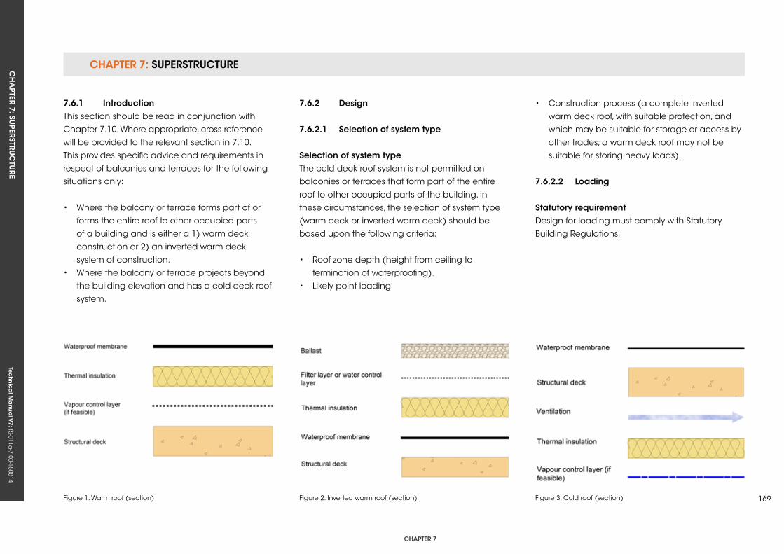
CHAPTER 7: SuPERSTRuCTuRECH
APTER 7: Su
PERSTRuC
TuRE
Tec
hn
ica
l Ma
nua
l V7: TS-011a
-7.00-180814
CHAPTER 7
169
7.6.1 introductionThis section should be read in conjunction with
Chapter 7.10. Where appropriate, cross reference
will be provided to the relevant section in 7.10.
This provides specific advice and requirements in
respect of balconies and terraces for the following
situations only:
• Where the balcony or terrace forms part of or
forms the entire roof to other occupied parts
of a building and is either a 1) warm deck
construction or 2) an inverted warm deck
system of construction.
• Where the balcony or terrace projects beyond
the building elevation and has a cold deck roof
system.
7.6.2 Design
7.6.2.1 selection of system type
selection of system typeThe cold deck roof system is not permitted on
balconies or terraces that form part of the entire
roof to other occupied parts of the building. In
these circumstances, the selection of system type
(warm deck or inverted warm deck) should be
based upon the following criteria:
• Roof zone depth (height from ceiling to
termination of waterproofing).
• Likely point loading.
• Construction process (a complete inverted
warm deck roof, with suitable protection, and
which may be suitable for storage or access by
other trades; a warm deck roof may not be
suitable for storing heavy loads).
7.6.2.2 Loading
statutory requirementDesign for loading must comply with Statutory
Building Regulations.
Figure 1: Warm roof (section) Figure 2: Inverted warm roof (section) Figure 3: Cold roof (section)
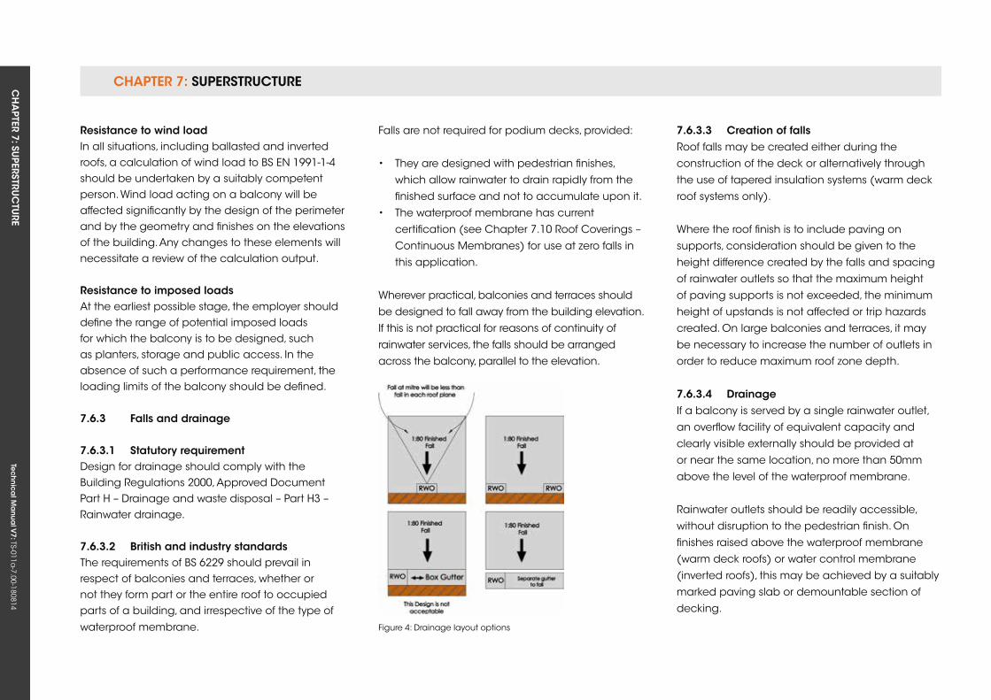
CHAPTER 7: SuPERSTRuCTuRE CH
APTER 7: Su
PERSTRuC
TuRE
Tec
hn
ica
l Ma
nua
l V7: TS-011a
-7.00-180814
resistance to wind loadIn all situations, including ballasted and inverted roofs, a calculation of wind load to BS EN 1991-1-4 should be undertaken by a suitably competent person. Wind load acting on a balcony will be affected significantly by the design of the perimeter and by the geometry and finishes on the elevations of the building. Any changes to these elements will necessitate a review of the calculation output.
resistance to imposed loadsAt the earliest possible stage, the employer should define the range of potential imposed loads for which the balcony is to be designed, such as planters, storage and public access. In the absence of such a performance requirement, the loading limits of the balcony should be defined.
7.6.3 falls and drainage
7.6.3.1 statutory requirementDesign for drainage should comply with the Building Regulations 2000, Approved Document Part H – Drainage and waste disposal – Part H3 – Rainwater drainage.
7.6.3.2 British and industry standardsThe requirements of BS 6229 should prevail in respect of balconies and terraces, whether or not they form part or the entire roof to occupied parts of a building, and irrespective of the type of
waterproof membrane.
Falls are not required for podium decks, provided:
• They are designed with pedestrian finishes,
which allow rainwater to drain rapidly from the
finished surface and not to accumulate upon it.
• The waterproof membrane has current
certification (see Chapter 7.10 Roof Coverings –
Continuous Membranes) for use at zero falls in
this application.
Wherever practical, balconies and terraces should
be designed to fall away from the building elevation.
If this is not practical for reasons of continuity of
rainwater services, the falls should be arranged
across the balcony, parallel to the elevation.
7.6.3.3 Creation of fallsRoof falls may be created either during the
construction of the deck or alternatively through
the use of tapered insulation systems (warm deck
roof systems only).
Where the roof finish is to include paving on
supports, consideration should be given to the
height difference created by the falls and spacing
of rainwater outlets so that the maximum height
of paving supports is not exceeded, the minimum
height of upstands is not affected or trip hazards
created. On large balconies and terraces, it may
be necessary to increase the number of outlets in
order to reduce maximum roof zone depth.
7.6.3.4 DrainageIf a balcony is served by a single rainwater outlet,
an overflow facility of equivalent capacity and
clearly visible externally should be provided at
or near the same location, no more than 50mm
above the level of the waterproof membrane.
Rainwater outlets should be readily accessible,
without disruption to the pedestrian finish. On
finishes raised above the waterproof membrane
(warm deck roofs) or water control membrane
(inverted roofs), this may be achieved by a suitably
marked paving slab or demountable section of
decking.
Figure 4: Drainage layout options
CHAPTER 7: SuPERSTRuCTuRECH
APTER 7: Su
PERSTRuC
TuRE
Tec
hn
ica
l Ma
nua
l V7: TS-011a
-7.00-180814
CHAPTER 7
171
Where rainwater downpipes from other higher
roof areas or balconies discharge via a lower
balcony or terrace, an open downpipe shoe is not
permitted. The downpipe should be connected
directly to the downpipe serving the lower balcony
or terrace.
7.6.4 Thermal performanceDesign for thermal performance must comply with
the current Building Regulations, as appropriate.
7.6.5 external fire performance
7.6.5.1 statutory requirementDesign for external fire performance must comply
with the current Building Regulations.
7.6.6 Provision for access
7.6.6.1 statutory requirementBalconies should have suitable access and
drainage meeting the requirements of the current
Building Regulations.
7.6.6.2 edge protectionThe guarding to the perimeter of balconies,
terraces and podium decks should be designed
to provide the simplest means of achieving
waterproofing integrity, given that installation of
balustrade or glazing stanchions may occur after
the installation of the roof system.
Acceptable examples include the following, in
order of preference:
• Full-height parapet walls.
• Stanchions or rails secured to low parapet walls
above the level of the waterproof membrane
(incorporated in copings or secured to
elevation).
• Stanchions secured, clamped and sealed to
stainless steel bolts set in raised plinths, which
were constructed prior to application of the
waterproof membrane (suitable for warm deck
and inverted warm deck roof systems).
• Stanchions secured, clamped and sealed to
stainless steel bolts set at deck level, which were
installed prior to application of the waterproof
membrane (suitable for warm deck roof systems
only).
If the design requires a collar of waterproof
membrane at the stanchion, the stanchion should
be of circular section at this point and should
incorporate a weathering apron.
7.6.6.3 Protection of waterproof system during constructionAt the earliest possible stage, the anticipated
loading of the balcony, terrace or podium area
by plant and access during service should be
assessed in terms of:
• Load, e.g. foot traffic, equipment
• Frequency
• Risk of impact
If such usage is intense or long-lasting during the
construction phase, consideration should be given
to temporary works only, with completion occurring
after all non-roofing usage has ceased, as follows:
• Warm deck roof system: installation of
temporary Vapour Control Layer (VCL), to be
overlaid when remainder of system is installed.
• Inverted warm deck roof system: overlay of
completed waterproof membrane with
geotextile and continuous temporary decking,
such as plywood, oriented strand board or
compatible recycled thermoplastic board.
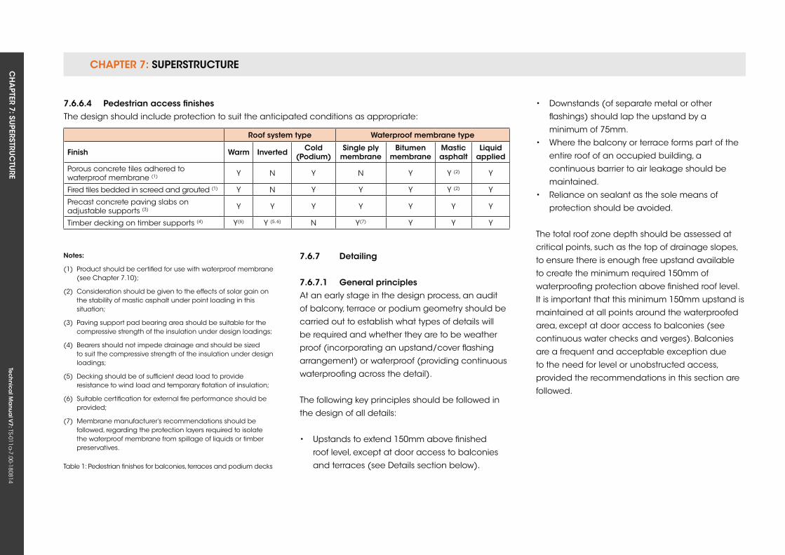
CHAPTER 7: SuPERSTRuCTuRE CH
APTER 7: Su
PERSTRuC
TuRE
Tec
hn
ica
l Ma
nua
l V7: TS-011a
-7.00-180814
7.6.7 Detailing
7.6.7.1 general principlesAt an early stage in the design process, an audit
of balcony, terrace or podium geometry should be
carried out to establish what types of details will
be required and whether they are to be weather
proof (incorporating an upstand/cover flashing
arrangement) or waterproof (providing continuous
waterproofing across the detail).
The following key principles should be followed in
the design of all details:
• upstands to extend 150mm above finished
roof level, except at door access to balconies
and terraces (see Details section below).
roof system type Waterproof membrane type
finish Warm inverted Cold (Podium)
single ply membrane
Bitumen membrane
Mastic asphalt
Liquid applied
Porous concrete tiles adhered to waterproof membrane (1) y N y N y y (2) y
Fired tiles bedded in screed and grouted (1) y N y y y y (2) y
Precast concrete paving slabs on adjustable supports (3) y y y y y y y
Timber decking on timber supports (4) y(6) y (5, 6) N y(7) y y y
notes:
(1) Product should be certified for use with waterproof membrane (see Chapter 7.10);
(2) Consideration should be given to the effects of solar gain on the stability of mastic asphalt under point loading in this situation;
(3) Paving support pad bearing area should be suitable for the compressive strength of the insulation under design loadings;
(4) Bearers should not impede drainage and should be sized to suit the compressive strength of the insulation under design loadings;
(5) Decking should be of sufficient dead load to provide resistance to wind load and temporary flotation of insulation;
(6) Suitable certification for external fire performance should be provided;
(7) Membrane manufacturer’s recommendations should be followed, regarding the protection layers required to isolate the waterproof membrane from spillage of liquids or timber preservatives.
• Downstands (of separate metal or other
flashings) should lap the upstand by a
minimum of 75mm.
• Where the balcony or terrace forms part of the
entire roof of an occupied building, a
continuous barrier to air leakage should be
maintained.
• Reliance on sealant as the sole means of
protection should be avoided.
The total roof zone depth should be assessed at
critical points, such as the top of drainage slopes,
to ensure there is enough free upstand available
to create the minimum required 150mm of
waterproofing protection above finished roof level.
It is important that this minimum 150mm upstand is
maintained at all points around the waterproofed
area, except at door access to balconies (see
continuous water checks and verges). Balconies
are a frequent and acceptable exception due
to the need for level or unobstructed access,
provided the recommendations in this section are
followed.
7.6.6.4 Pedestrian access finishesThe design should include protection to suit the anticipated conditions as appropriate:
Table 1: Pedestrian finishes for balconies, terraces and podium decks
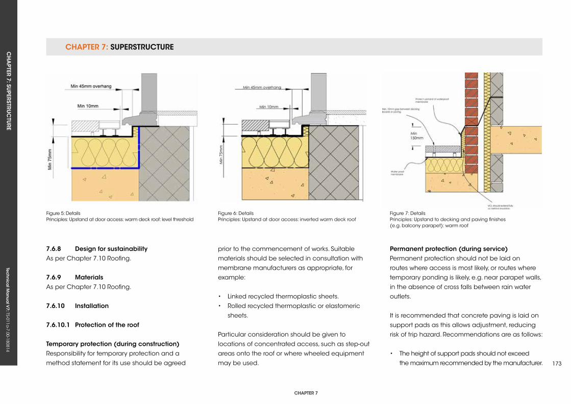
CHAPTER 7: SuPERSTRuCTuRECH
APTER 7: Su
PERSTRuC
TuRE
Tec
hn
ica
l Ma
nua
l V7: TS-011a
-7.00-180814
CHAPTER 7
173
Figure 5: Details Principles: upstand at door access: warm deck roof: level threshold
Figure 6: DetailsPrinciples: upstand at door access: inverted warm deck roof
Figure 7: DetailsPrinciples: upstand to decking and paving finishes (e.g. balcony parapet): warm roof
7.6.8 Design for sustainabilityAs per Chapter 7.10 Roofing.
7.6.9 MaterialsAs per Chapter 7.10 Roofing.
7.6.10 installation
7.6.10.1 Protection of the roof
Temporary protection (during construction)Responsibility for temporary protection and a
method statement for its use should be agreed
prior to the commencement of works. Suitable
materials should be selected in consultation with
membrane manufacturers as appropriate, for
example:
• Linked recycled thermoplastic sheets.
• Rolled recycled thermoplastic or elastomeric
sheets.
Particular consideration should be given to
locations of concentrated access, such as step-out
areas onto the roof or where wheeled equipment
may be used.
Permanent protection (during service)Permanent protection should not be laid on
routes where access is most likely, or routes where
temporary ponding is likely, e.g. near parapet walls,
in the absence of cross falls between rain water
outlets.
It is recommended that concrete paving is laid on
support pads as this allows adjustment, reducing
risk of trip hazard. Recommendations are as follows:
• The height of support pads should not exceed
the maximum recommended by the manufacturer.
CHAPTER 7: SuPERSTRuCTuRE CH
APTER 7: Su
PERSTRuC
TuRE
Tec
hn
ica
l Ma
nua
l V7: TS-011a
-7.00-180814
• Paving should not be cut.
• Paving should be firmly butted up against
support pad separating pegs.
• Support pad separating pegs should provide
clear space for rapid disposal of rain water
between paving slabs.
• Provision for movement at perimeters should
comprise either a 75mm margin of washed
stone or a compressible rubberised fill. In either
case, drainage should not be obstructed and
a suitable restraint trim should be used to ensure
stone does not fall beneath the paving
adjacent.
7.6.10.2 vapour Control Layer (vCL)As per Chapter 7.10 Roofing.
7.6.10.3 Thermal insulationAs per Chapter 7.10 Roofing.
7.6.10.4 Waterproof membraneAs per Chapter 7.10 Roofing.
7.6.11 Testing
7.6.11.1 final inspectionAt practical completion of the balcony, terrace or
podium deck, all areas should be clear of stored
material, other site operations and all protection.
A thorough, recorded, visual inspection of all
areas, including details, should be carried out with
representation from the General Contractor and
Roofing Contractor in attendance.
7.6.11.2 Procurement of testing servicesIf testing to demonstrate waterproofing integrity is
required, it should be undertaken by a third-party
that is independent of the roofing contract. The
testing service provider should provide evidence of
the following:
• Efficacy of the method proposed in the
circumstances of the project.
• Experience and training of operator.
• Membership of an appropriate trade
association that sets a Code of Conduct for the
service.
7.6.11.3 Methods of test
Low voltage earth leakageLow voltage earth leakage is a safe and effective
method for the testing of waterproofing integrity
in roofs, where the waterproof membrane is an
electrical insulator and the deck provides an
electrical earth. It is not suitable for testing flat
roofs where the waterproof membrane has been
overlaid with insulation and ballast (inverted roofs)
or ballast only (ballasted warm roofs); therefore,
testing should be carried out prior to completion of
the roofing system.
High voltage electrical discharge The high voltage electrical discharge method is
best suited to the testing of continuous thin films,
such as liquid-applied coatings. Its use is not
recommended with polymeric single ply, reinforced
bitumen membranes and mastic asphalt.
vacuum Vacuum testing of seams of membranes
manufactured off-site is an effective means of
quality assessment, but is not recommended as a
method of demonstrating the integrity of flat roofs.
flood testingFlood testing is a suitable method of demonstrating
the integrity of balconies, terraces and podium
decks. However, consideration should be given to
the effect of possible ingress to the construction
during the test and risk of entrapped water in
insulation (warm deck roofs) and decks (all types).
The area under any one test should not exceed
50m2.
CHAPTER 7: SuPERSTRuCTuRECH
APTER 7: Su
PERSTRuC
TuRE
Tec
hn
ica
l Ma
nua
l V7: TS-011a
-7.00-180814
CHAPTER 7
175
7.6.12 Provision of information
7.6.12.1 operation and maintenance Manual The following information is required:
• Specification, as-built:
- Waterproof membrane: generic type,
product(s) and (as appropriate) thickness.
- Thermal insulation: generic type, product(s)
and thickness.
- Acoustic insulation: generic type, product
and (as appropriate) thickness.
- Vapour Control Layer: generic type, product
(as appropriate) and thickness (as
appropriate).
- Rainwater outlets: type, product, capacity,
location and means of access.
• Procedure for maintenance of waterproof
membrane, including (where appropriate)
recommended frequency and method of
application of solar reflective finish.
• Procedure for repair of waterproof membrane.
Tec
hn
ica
l Ma
nua
l V6: TS-011a
-6.00-010413Te
ch
nic
al M
anu
al V
7: TS-011a-7.00-180814
FUNCTIONAL REQUIREMENTS
7.7 CLADDing
Workmanshipi. All workmanship must be within the tolerances defined in Chapter 1
of this Manual.
ii. All work is to be carried out by a technically competent person in
a workmanlike manner.
iii. Certification is required for any work completed by an approved
installer.
Materialsi. All materials should be handled and stored correctly in a manner that
will not cause damage or deterioration of the product.
ii. All materials, products and building systems shall be appropriate and
suitable for their intended purpose.
iii. The structure shall, unless specifically agreed otherwise with the
Warranty provider, have a life of not less than 60 years. Individual
components and assemblies that can be inspected and replaced
and which are not integral to the structure may have a lesser
durability, but not in any circumstances less than 15 years.
Designi. The design and specifications shall provide a clear indication of the
design intent and demonstrate a satisfactory level of performance.
ii. The cladding materials, design and construction must meet the
relevant Building Regulations, British Standards, Eurocodes and other
statutory requirements.
iii. The design of primary framing members (e.g. mullions and transoms,
backing wall framing sections, etc.) and the connections of these
members/panels to the structure must be supported by structural
calculations provided by a suitably qualified professional.
CHAPTER 7: SuPERSTRuCTuRECH
APTER 7: Su
PERSTRuC
TuRE
Tec
hn
ica
l Ma
nua
l V7: TS-011a
-7.00-180814
CHAPTER 7
177
7.7.1 renderRendering should be in accordance with BS 5262
and workmanship in accordance with BS 8000.
In particular, the following should be considered:
• Abutments between cement render and other
cladding materials or components should be
weather tight and allow for differential
movement.
• Any joints in the wall where movement may
occur should be continued through the
rendering.
• Render should not bridge the Damp Proof
Course (DPC) and be finished onto a durable
render stop.
• External rendering should comply with BS 5262.
• Sand for rendering should be stored separately
from other building and concreting sands.
• For bellcasts, a galvanised steel bead is
acceptable.
• For other beads and stops, an epoxy or PVC-
coated galvanised steel is acceptable.
• Render systems that include a cavity as a
secondary defence system should also
incorporate cavity barriers within the cavity
to prevent the spread of fire through the cavity.
The cavity barriers should not obstruct more
than 50% of the cavity. The cavity must retain its
ability to drain. The cavity barrier must activate
and fully close the cavity when exposed to fire.
• Renders will be reinforced at corners and
penetrations.
• Renders installed between pedestrian level
and 6.0m above ground level will be designed
to accommodate higher maintenance and
impact loads in accordance with Table 2 of
BS 8200.
7.7.1.1 Timber frame backgroundA drained and vented cavity should be provided
behind render on timber frame construction. The
mesh or metal lathing used should be approved
by an independent authority and fixed to vertical
battens at stud centres. The minimum size of the
cavity should be 19mm when the mesh or metal
lathing is backed by a water-resistant membrane,
and 50mm when the mesh or metal lathing is
unbacked. A DPC should be provided between
unbacked render and timber battens.
Battens should be either 25mm x 38mm or
50mm x 50mm, preservative treated (BS 8417, or
equivalent, hazard class 2) and fixed at spacings
recommended in BS 5262. Fixings and preservatives
should be compatible.
Battens should be fixed to each stud with annular
ring nails of length at least twice the batten
thickness plus the sheathing thickness. Nails should
be hot dipped galvanised stainless steel or equally
durable. Where cavity barriers are required, they
should be correctly fitted without gaps, fill the cavity
and be fixed with stainless steel staples or equally
durable fixings. Maintain settlement joints below
external frames and soffits.
Where cement render spans across an
intermediate floor zone in timber frame
construction, allow for differential movement due
to timber shrinkage by incorporating a movement
joint. Vertical movement joints should also be
provided at maximum 5m horizontal centres.
7.7.1.2 Masonry backgroundWalls should be examined for excessive moisture
content prior to rendering. This is particularly
important where the masonry background has
no upper limit on its soluble salts content, e.g. N
designation clay bricks. Sulphate-resisting cement
should be employed in the render and mortar
used for parapets, chimneys, retaining walls and
walls below DPC level with this background.
It is recommended that:
• The backs and exposed horizontal surfaces
of parapets are not rendered.
• Throats or drips to copings of parapets and
chimneys should project beyond the finished
faces to throw water clear.
CHAPTER 7: SuPERSTRuCTuRE CH
APTER 7: Su
PERSTRuC
TuRE
Tec
hn
ica
l Ma
nua
l V7: TS-011a
-7.00-180814
• Rendering to chimneys should only be carried
out where brickwork contains little or no
sulphates. Splatterdash treatment should be used.
• As before, horizontal DPC and damp proof
membranes (DPM) must not be bridged.
• Rendering is not used below DPC. However,
where this is not practical, the render must still
not be allowed to bridge the DPC. A bellcast
must be formed in the render above the DPC.
7.7.1.3 other construction detailingEnsure that drips and throating to sills, coping, etc.
project beyond the face of the finished render
above the DPC.
Notwithstanding wind loadings, the larger the
eaves overhang the better. This will provide
protection to the top joint and prevent rain water
percolating behind the render.
Angles, stop beads and jointing sections should
be secured with drilled or shot-fired fixings, and not
with gypsum plaster.
Check whether the rendering can be applied
directly onto the wall, or whether any preparatory
treatment is required in accordance with the
manufacturer’s instructions.
The surface should be checked for suction by
dampening the wall with clean water.
7.7.1.4 vertical and horizontal flatnessRendering should have a maximum vertical and
horizontal deviation from flatness of +/-10mm in 5m,
and is measured in a similar way to straightness on
plan and plumb of masonry.
7.7.2 Curtain walling
7.7.2.1 generalCurtain walling systems should have third-party
certification confirming satisfactory assessment,
and comply with the requirements of the CWCT
Standard for Systemised Building Envelopes,
including the following sections:
• Part 1: Scope, terminology, testing and
classification.
• Part 2: Loadings, fixings and movement.
• Part 3: Air, water and wind resistance.
• Part 4: Operable components, additional
elements and means of access.
• Part 5: Thermal, moisture and acoustic
performance.
• Part 6: Fire performance.
• Part 7: Robustness, durability, tolerances and
workmanship.
• Part 8: Testing.
The CWCT Standard provides detailed guidance
on performance and testing.
Dead and live loads should be transferred safely to
the building structure without undue permanent
deformation or deflection of any component.
Imposed loads should be calculated in
accordance with BS EN 1991. Movement should
be accommodated without any reduction in
performance.
Fixings and supports should be designed to
accommodate specified loads and take account
of the product manufacturer’s recommendations.
CE marking is to be provided for all curtain walling
covered by EN 13830 in buildings constructed after
July 2013, and will therefore include the following
curtain wall types:
• Stick construction
• unitised construction
• Double skin walls
• Structural sealant glazing
• Bolted glazing
Cavity barriers and fire stops should be provided in
accordance with relevant Building Regulations.
CHAPTER 7: SuPERSTRuCTuRECH
APTER 7: Su
PERSTRuC
TuRE
Tec
hn
ica
l Ma
nua
l V7: TS-011a
-7.00-180814
CHAPTER 7
179
7.7.2.2 TestingThe curtain wall system will have been tested and
provided with a classification given in BS EN 13830.
Pull-out or destructive testing of anchors should be
carried out in accordance with BS 5080 and the
Construction Fixings Association Guidance Note,
Procedure for Site Testing Construction Fixings.
Packing of brackets to achieve surface tolerance
should be permitted only in accordance with the
manufacturer’s recommendations, and should
not exceed the maximum depth stated in the
Designer’s calculations.
All packers for brackets supporting or restraining
the curtain wall must be metal.
The completed curtain wall system should resist
the passage of water to the inside of the building,
allowing free drainage and not trapping water, and
should have:
• External and internal air and water seals.
• Drained and ventilated glazing rebates.
Sealants should be specified in accordance with
BS 6213 or BS EN 15651, and the performance
determined by BS EN 11600 and the manufacturer’s
recommendations.
The system should be designed to minimise the
risk of surface and interstitial condensation by the
use of thermal breaks and a continuous Vapour
Control Layer. It should be designed to resist the
passage of airborne and impact sound within the
building, and particular attention should be given
to flanking transmission at:
• The edges of separating floors.
• The outer edges of separating walls.
• The outer edges of partition walls.
• The junctions with roof constructions
and parapets.
Where curtain wall members run uninterrupted past
floor slabs and partition walls, consideration must be
given to structure-borne sound (impact sound).
It should comply with BS 7671 Requirements for
electrical installations for electrical continuity and
earth bonding, and where it is required to form
part of a lightning protection system it must be
designed to comply with the requirements of BS
6651.
The risk of bimetallic corrosion should be avoided
through the isolation of dissimilar metals.
The curtain wall system should not include
materials liable to infestation attack by
micro-organisms, fungi, insects or vermin.
7.7.2.3 TolerancesDesign should allow for the line, level, plumb and
plane of the completed curtain wall to be within
the acceptable tolerances of:
• Line: +/-2mm in any one storey height or
structural bay width, and +/-5mm overall.
• Level: +/-2mm of horizontal in any one structural
bay width, and +/-5mm overall.
• Plumb: +/-2mm of vertical in any one structural
bay width, and +/-5mm overall.
• Plane: +/-2mm of the principle plane in any
one storey height or structural bay width, and
+/- 5mm overall.
7.7.3 insulated render systemsThese are systems applied to the exterior walls of
existing or new buildings, comprising of an insulant
and a weather protective finish, of which there are
three main types:
• Traditional renders and finishes.
• Thin coat renders and synthetic finishes.
• Pre-formed cladding materials.
All insulated render systems must have appropriate
third-party certification.
CHAPTER 7: SuPERSTRuCTuRE CH
APTER 7: Su
PERSTRuC
TuRE
Tec
hn
ica
l Ma
nua
l V7: TS-011a
-7.00-180814
7.7.4 Timber claddingTimber and boards for exterior use should be of
a durable species, with sapwood excluded, or
preservative treated by pressure impregnation
using preservatives suitable for use in hazard Class
3 in compliance with BS 8417: 2003, or equivalent.
Further guidance on the durability of timber is
provided in Chapter 2 – Materials.
Where timber boarding or plywood spans across
an intermediate floor zone in a timber frame
construction, allow for differential movement
caused through timber shrinkage by incorporating
a movement joint.
Where cavity barriers are required, they should be
correctly fitted without gaps, fill the cavity and be
fixed with stainless steel staples or equally durable
fixings.
Abutments between cladding and other weather-
resisting elements should be neatly made,
weather tight and allow for differential movement.
Workmanship should comply with BS 8000: 5.
7.7.4.1 Timber boardingTimber boarding should be at least 16mm thick,
and allowance for moisture movement in boarding
should be achieved by making tongues, joints or
overlaps at least 10% of the board width.
Timber boarding should be battened off the
supporting background to provide a minimum
19mm cavity for draining and venting.
Battens should be a minimum of 38mm wide,
preservative treated and at maximum 600mm
centres. A breather membrane should always
be installed when horizontal battens are located
against the sheathing. Battens on timber frame
should be fixed to each stud (and not to the
sheathing) with annular ring nails of length at
least twice the batten thickness plus the sheathing
thickness (or plain shank nails of length 2.5 times
the batten thickness plus the sheathing thickness).
Boards should be fixed to battens by face or secret
nailing with annular ring nails at least twice the
board thickness or plain shank nails at least 2.5
times the board thickness.
Butt joints at board ends should occur at battens.
Nails should be either hot dipped galvanised,
stainless steel or equally durable. Aluminium nails
should not be used with timber treated with a
preservative containing copper. Galvanised nails
should not be used with Western Red Cedar.

Tec
hn
ica
l Ma
nua
l V6: TS-011a
-6.00-010413Te
ch
nic
al M
anu
al V
7: TS-011a-7.00-180814
FUNCTIONAL REQUIREMENTS
181
7.8 roof sTruCTure
Workmanshipi. All workmanship must be within the tolerances defined in Chapter 1
of this Manual.
ii. All work is to be carried out by a technically competent person in
a workmanlike manner.
Materialsi. All materials should be stored correctly in a manner that will not cause
damage or deterioration of the product.
ii. All materials, products and building systems shall be appropriate and
suitable for their intended purpose.
iii. The structure shall, unless specifically agreed otherwise with the
Warranty provider, have a life of not less than 60 years. Individual
components and assemblies, not integral to the structure, may have
a lesser durability, but not in any circumstances less than 15 years.
Designi. The design and specifications shall provide a clear indication of the
design intent and demonstrate a satisfactory level of performance.
ii. Structural elements outside the parameters of regional Approved
Documents must be supported by structural calculations provided by
a suitably qualified expert.
iii. The materials, design and construction must meet the relevant
Building Regulations, British Standards, Eurocodes and other statutory
requirements.
CHAPTer 7

CHAPTER 7: SuPERSTRuCTuRE CH
APTER 7: Su
PERSTRuC
TuRE
Tec
hn
ica
l Ma
nua
l V7: TS-011a
-7.00-180814
7.8.1 statutory requirements
roof structure and loadingRoof framing and rafter design must be in
accordance with current Building Regulations.
The roof of the building shall be constructed so
that the combined dead, imposed and wind loads
are sustained and transmitted by it to the ground
safely, and without causing such deflection or
deformation of any part of the building, or such
movement of the ground, as to impair the stability
of any part of another building.
Section 2A of Approved Document A (England and
Wales) gives basic requirements for the stability of
low rise residential buildings. With respect to the
roof, it requires that the structure should be of such
construction that it has adequate interconnection
with the walls, allowing it to act as a horizontal
diaphragm capable of transferring the wind forces
to buttressing elements of the building.
In this respect, it is acknowledged that a traditional
cut roof, i.e. using rafters, purlins and ceiling
joists, generally has sufficient built-in resistance
to instability and wind forces, e.g. from either
hipped ends, tiling battens, rigid sarking or the
like. However, the need for diagonal rafter bracing
equivalent to that recommended in BS EN 1995-1:
2004+A1, or Annex H of BS 8103-3 for trussed rafter
roofs, should be considered, especially for
single-hipped and non-hipped roofs of more
than 40° for detached houses.
Section 2B of Approved Document A (England and
Wales) contains advice on ‘sizing of certain timber
members in floors and roofs for dwellings’, and
refers the Designer to the following sources:
• Span tables for solid timber members in floors,
ceilings and roofs (excluding trussed rafter
roofs) for dwellings. Published by TRADA.
• BS 8103-3, Structure design of low rise buildings,
Code of Practice for timber floors and roofs for
dwellings.
• BS EN 1995-1: 2004+A1, Eurocode 5 design of
timber structures. General. Common rules and
rules for buildings.
section 2C of Approved Document A The design criteria set out is intended to be
adequate for imposed roof loads of 1.00kN/m2
for spans not exceeding 12m, and 1.50kN/m2 for
spans not exceeding 6m.
All structural timber used in a conventional cut roof,
i.e. rafters, purlins, ceiling joists, binders and other
timber elements, should be stress graded. All such
timber must be stamped as either ‘DRy’ or ‘kD’ (kiln
Dry). The use of ungraded, or ‘green’, timber is not
acceptable.
Allowances for wind loading The need for a roof to withstand wind pressure and
suction will be met if the proposed roof is braced
effectively, as discussed elsewhere in this Manual,
and secured to the structure, as detailed below,
with walls adequately restrained.
The securing of roofs to the supporting structure
roof timbers normally involves a timber wall plate
or similar, which should be levelled using a spirit
level so that loadings from the roof are directed
perpendicularly down the supporting wall.
The wall plate may, as good practice, be fixed to
ensure correct positioning when roof timbers or
trusses are being installed by means of galvanised
mild steel holding down straps (30mm x 5mm x
1,000mm long at maximum 2m centres) nailed
to the wall plate and securely fixed to the inner
surface of the wall with compatible fixings.
There is a need to ensure that holding down straps
are provided in areas of severe wind exposure
where required by the roof design.
7.8.2 Treatment of timberPreservative treatment of roof timbers is normally
unnecessary, except where specifically required
under relevant standards and Codes of Practice,
and in the following circumstances:
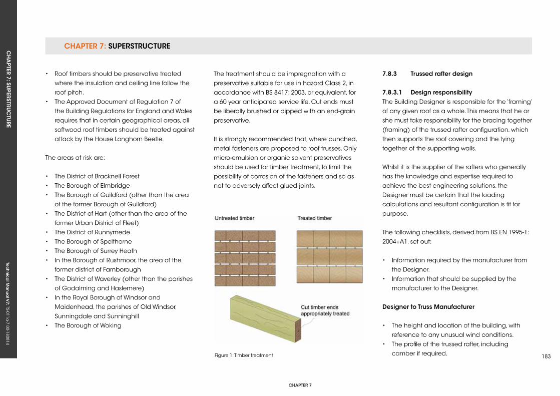
CHAPTER 7: SuPERSTRuCTuRECH
APTER 7: Su
PERSTRuC
TuRE
Tec
hn
ica
l Ma
nua
l V7: TS-011a
-7.00-180814
CHAPTER 7
183
• Roof timbers should be preservative treated
where the insulation and ceiling line follow the
roof pitch.
• The Approved Document of Regulation 7 of
the Building Regulations for England and Wales
requires that in certain geographical areas, all
softwood roof timbers should be treated against
attack by the House Longhorn Beetle.
The areas at risk are:
• The District of Bracknell Forest
• The Borough of Elmbridge
• The Borough of Guildford (other than the area
of the former Borough of Guildford)
• The District of Hart (other than the area of the
former urban District of Fleet)
• The District of Runnymede
• The Borough of Spelthorne
• The Borough of Surrey Heath
• In the Borough of Rushmoor, the area of the
former district of Farnborough
• The District of Waverley (other than the parishes
of Godalming and Haslemere)
• In the Royal Borough of Windsor and
Maidenhead, the parishes of Old Windsor,
Sunningdale and Sunninghill
• The Borough of Woking
The treatment should be impregnation with a
preservative suitable for use in hazard Class 2, in
accordance with BS 8417: 2003, or equivalent, for
a 60 year anticipated service life. Cut ends must
be liberally brushed or dipped with an end-grain
preservative.
It is strongly recommended that, where punched,
metal fasteners are proposed to roof trusses. Only
micro-emulsion or organic solvent preservatives
should be used for timber treatment, to limit the
possibility of corrosion of the fasteners and so as
not to adversely affect glued joints.
7.8.3 Trussed rafter design
7.8.3.1 Design responsibilityThe Building Designer is responsible for the ‘framing’
of any given roof as a whole. This means that he or
she must take responsibility for the bracing together
(framing) of the trussed rafter configuration, which
then supports the roof covering and the tying
together of the supporting walls.
Whilst it is the supplier of the rafters who generally
has the knowledge and expertise required to
achieve the best engineering solutions, the
Designer must be certain that the loading
calculations and resultant configuration is fit for
purpose.
The following checklists, derived from BS EN 1995-1:
2004+A1, set out:
• Information required by the manufacturer from
the Designer.
• Information that should be supplied by the
manufacturer to the Designer.
Designer to Truss Manufacturer
• The height and location of the building, with
reference to any unusual wind conditions.
• The profile of the trussed rafter, including
camber if required.Figure 1: Timber treatment
CHAPTER 7: SuPERSTRuCTuRE CH
APTER 7: Su
PERSTRuC
TuRE
Tec
hn
ica
l Ma
nua
l V7: TS-011a
-7.00-180814
• The span of the trussed rafter.
• The pitch or pitches of the roof.
• The method of support and position of supports.
• The type or weights of roof tiles or covering,
including sarking, insulation and ceiling
materials.
• The size and approximate position of any water
tanks or other equipment to be supported on
the trussed rafters.
• The overhang of the rafters at eaves, and other
eaves details.
• The positions and dimensions of hatches,
chimneys and other openings.
• The service use of the building, with reference
to any unusual environmental conditions and
the type of preservative treatment where
required.
• The spacing of trussed rafters and special
timber sizes where these are required to match
existing construction.
Truss Manufacturer to Designer
• Finished sizes, species, stress grades or strength
classes of timber members.
• The type, sizes and positions of all jointing
devices with tolerances, or the number of
effective teeth or nails required in each member
at each joint.
• The positions and sizes of all bearings.
• Loadings and other conditions for which the
trussed rafters are designed.
• The spacing of trussed rafters.
• The positions, fixings and sizes of any lateral
supports necessary to prevent buckling of
compression members, such as rafters and
struts. (Details of the permanent bracing
necessary to ensure the overall stability of the
complete roof structure and supporting walls
should be provided by the Building Designer).
• The method of support for tanks and ancillary
equipment, together with the capacity or
magnitude of additional load assumed.
• The range of reactions to be accommodated
at the support positions, including those
required to resist wind uplift forces.
• The basis of the design.
• Details of any changes in spacing to
accommodate chimneys or openings.
• Any special precautions for handling and
erection, in addition to those covered by
BS EN 1995-1: 2004+A1.
7.8.3.2 spansMaximum permissible spans for the most common
building types and rafter configurations are given
in BS EN 1995-1: 2004+A1 Section 9. For designs that
fall outside BS EN 1995-1: 2004+A1 conditions, the
trussed rafter must demonstrate adequate jointing
and structural integrity by calculation.
7.8.3.3 LoadsTrussed rafters and the framed roof must support
the dead loads as specified in BS EN 1991-1 and
BS EN 1991-1-7, the wind loads in BS EN 1991-1-4:
2005+A1 and the imposed loads in BS EN 1991-1-
3. Loads acting on rafters are dead loads (tiles/
slates, battens, underlay and rafter self-weight),
imposed loads (snow load and maintenance) and
the wind uplift load. Other dead loads that act on
the ceiling ties (ceiling, insulation, water tanks and
the tie self-weight) and imposed loads (loft access
and weight of storage) will also have to be taken
into account by the Designer.
BS EN 1991-1 and BS EN 1991-1-7 specify the
following limits for imposed loads on the rafters
uniformly distributed over the whole roof, measured
on plan:
• Roofs pitched 10° to 30°: 0.75kN/m2.
• Roofs pitched 31° to 75°: 0.75kN/m2 – 0 kN/m2
(reduced linearly).
Or:
• A concentrated load of 0.9kN, whichever
produces the greater stress or deflection.
Experience shows that for most common tiled and
slated roofs, the uniformly distributed load is more
severe.
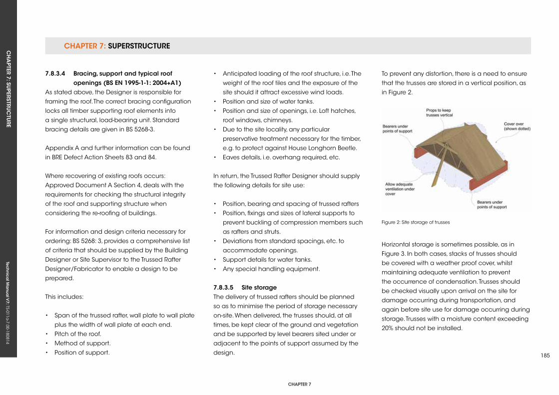
CHAPTER 7: SuPERSTRuCTuRECH
APTER 7: Su
PERSTRuC
TuRE
Tec
hn
ica
l Ma
nua
l V7: TS-011a
-7.00-180814
CHAPTER 7
185
7.8.3.4 Bracing, support and typical roof openings (Bs en 1995-1-1: 2004+A1)As stated above, the Designer is responsible for
framing the roof. The correct bracing configuration
locks all timber supporting roof elements into
a single structural, load-bearing unit. Standard
bracing details are given in BS 5268-3.
Appendix A and further information can be found
in BRE Defect Action Sheets 83 and 84.
Where recovering of existing roofs occurs:
Approved Document A Section 4, deals with the
requirements for checking the structural integrity
of the roof and supporting structure when
considering the re-roofing of buildings.
For information and design criteria necessary for
ordering: BS 5268: 3, provides a comprehensive list
of criteria that should be supplied by the Building
Designer or Site Supervisor to the Trussed Rafter
Designer/Fabricator to enable a design to be
prepared.
This includes:
• Span of the trussed rafter, wall plate to wall plate
plus the width of wall plate at each end.
• Pitch of the roof.
• Method of support.
• Position of support.
• Anticipated loading of the roof structure, i.e. The
weight of the roof tiles and the exposure of the
site should it attract excessive wind loads.
• Position and size of water tanks.
• Position and size of openings, i.e. Loft hatches,
roof windows, chimneys.
• Due to the site locality, any particular
preservative treatment necessary for the timber,
e.g. to protect against House Longhorn Beetle.
• Eaves details, i.e. overhang required, etc.
In return, the Trussed Rafter Designer should supply
the following details for site use:
• Position, bearing and spacing of trussed rafters
• Position, fixings and sizes of lateral supports to
prevent buckling of compression members such
as rafters and struts.
• Deviations from standard spacings, etc. to
accommodate openings.
• Support details for water tanks.
• Any special handling equipment.
7.8.3.5 site storageThe delivery of trussed rafters should be planned
so as to minimise the period of storage necessary
on-site. When delivered, the trusses should, at all
times, be kept clear of the ground and vegetation
and be supported by level bearers sited under or
adjacent to the points of support assumed by the
design.
To prevent any distortion, there is a need to ensure
that the trusses are stored in a vertical position, as
in Figure 2.
Horizontal storage is sometimes possible, as in
Figure 3. In both cases, stacks of trusses should
be covered with a weather proof cover, whilst
maintaining adequate ventilation to prevent
the occurrence of condensation. Trusses should
be checked visually upon arrival on the site for
damage occurring during transportation, and
again before site use for damage occurring during
storage. Trusses with a moisture content exceeding
20% should not be installed.
Figure 2: Site storage of trusses
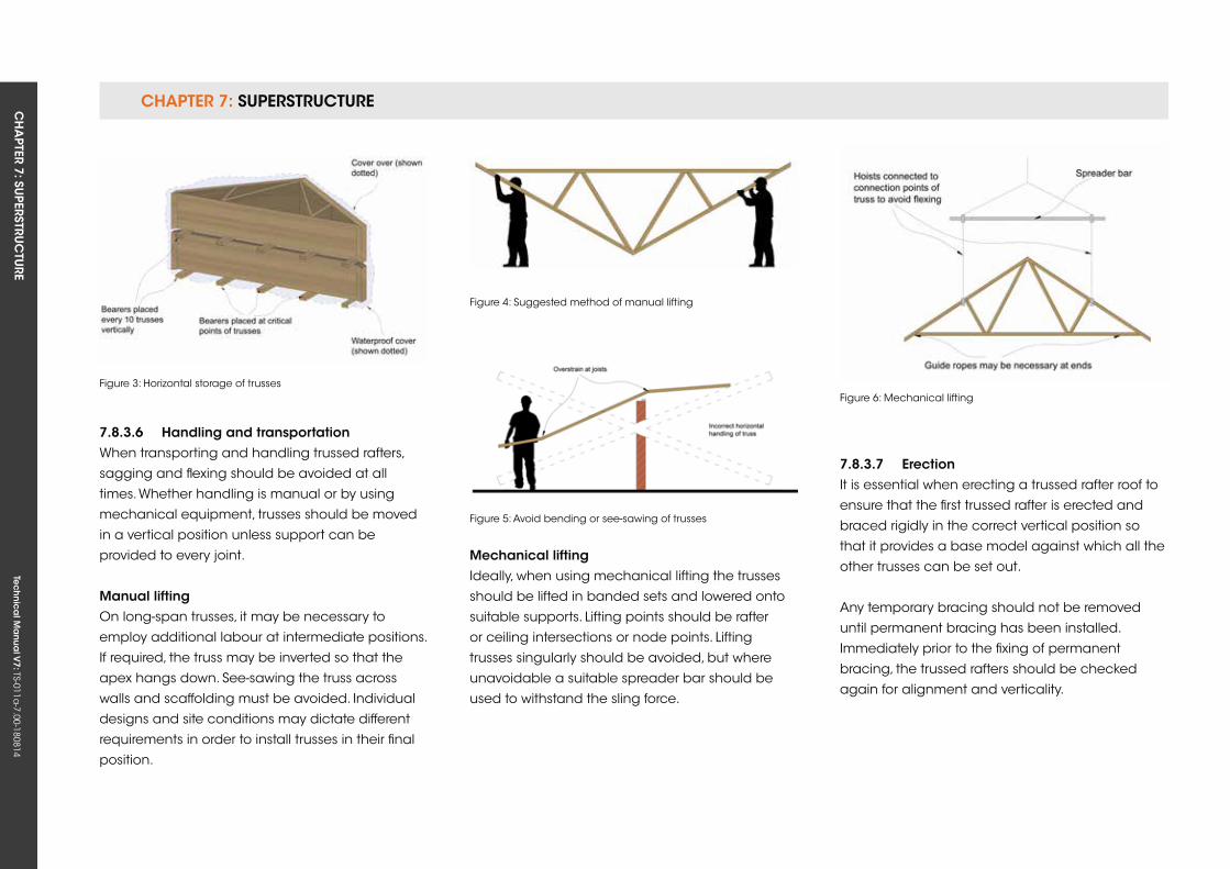
CHAPTER 7: SuPERSTRuCTuRE CH
APTER 7: Su
PERSTRuC
TuRE
Tec
hn
ica
l Ma
nua
l V7: TS-011a
-7.00-180814
7.8.3.6 Handling and transportationWhen transporting and handling trussed rafters,
sagging and flexing should be avoided at all
times. Whether handling is manual or by using
mechanical equipment, trusses should be moved
in a vertical position unless support can be
provided to every joint.
Manual liftingOn long-span trusses, it may be necessary to
employ additional labour at intermediate positions.
If required, the truss may be inverted so that the
apex hangs down. See-sawing the truss across
walls and scaffolding must be avoided. Individual
designs and site conditions may dictate different
requirements in order to install trusses in their final
position.
Figure 3: Horizontal storage of trusses
Figure 4: Suggested method of manual lifting
Mechanical liftingIdeally, when using mechanical lifting the trusses
should be lifted in banded sets and lowered onto
suitable supports. Lifting points should be rafter
or ceiling intersections or node points. Lifting
trusses singularly should be avoided, but where
unavoidable a suitable spreader bar should be
used to withstand the sling force.
Figure 5: Avoid bending or see-sawing of trusses
Figure 6: Mechanical lifting
7.8.3.7 erectionIt is essential when erecting a trussed rafter roof to
ensure that the first trussed rafter is erected and
braced rigidly in the correct vertical position so
that it provides a base model against which all the
other trusses can be set out.
Any temporary bracing should not be removed
until permanent bracing has been installed.
Immediately prior to the fixing of permanent
bracing, the trussed rafters should be checked
again for alignment and verticality.
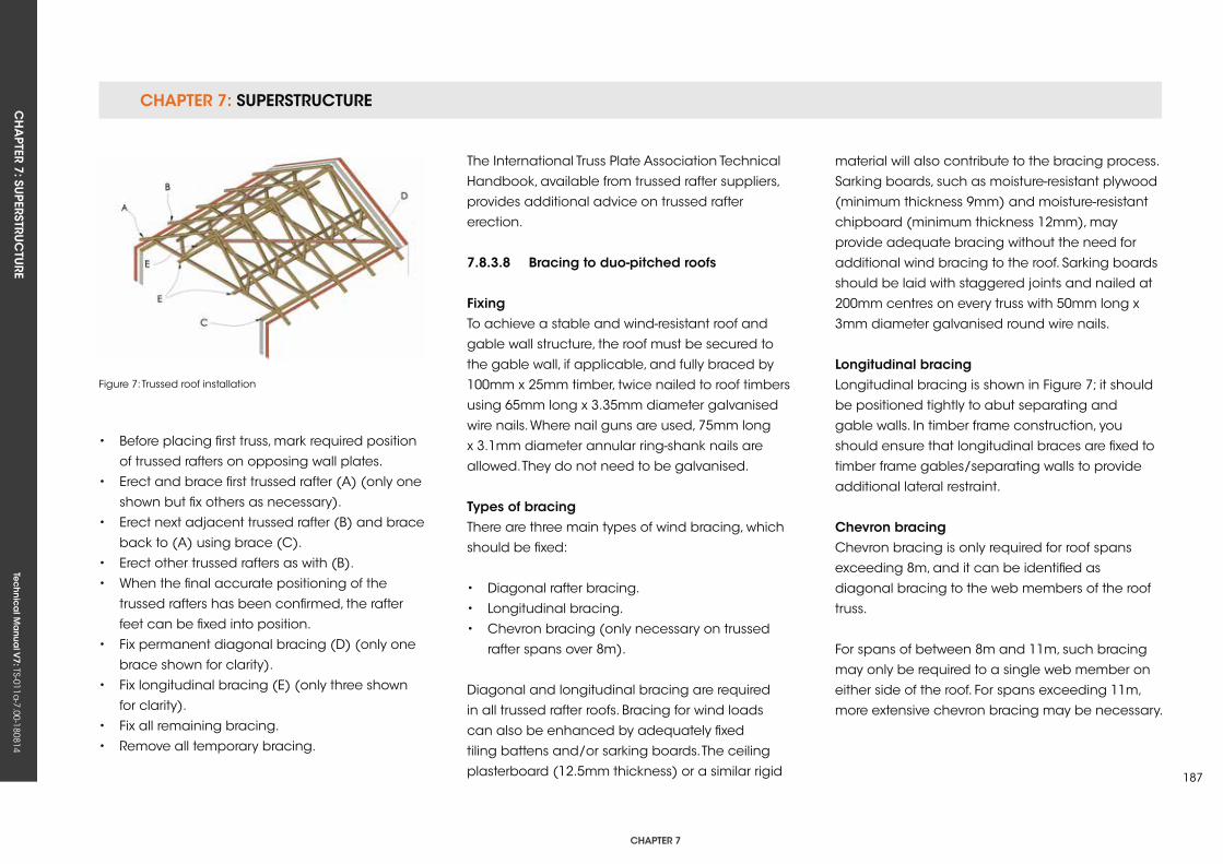
CHAPTER 7: SuPERSTRuCTuRECH
APTER 7: Su
PERSTRuC
TuRE
Tec
hn
ica
l Ma
nua
l V7: TS-011a
-7.00-180814
CHAPTER 7
187
• Before placing first truss, mark required position
of trussed rafters on opposing wall plates.
• Erect and brace first trussed rafter (A) (only one
shown but fix others as necessary).
• Erect next adjacent trussed rafter (B) and brace
back to (A) using brace (C).
• Erect other trussed rafters as with (B).
• When the final accurate positioning of the
trussed rafters has been confirmed, the rafter
feet can be fixed into position.
• Fix permanent diagonal bracing (D) (only one
brace shown for clarity).
• Fix longitudinal bracing (E) (only three shown
for clarity).
• Fix all remaining bracing.
• Remove all temporary bracing.
Figure 7: Trussed roof installation
The International Truss Plate Association Technical
Handbook, available from trussed rafter suppliers,
provides additional advice on trussed rafter
erection.
7.8.3.8 Bracing to duo-pitched roofs
fixingTo achieve a stable and wind-resistant roof and
gable wall structure, the roof must be secured to
the gable wall, if applicable, and fully braced by
100mm x 25mm timber, twice nailed to roof timbers
using 65mm long x 3.35mm diameter galvanised
wire nails. Where nail guns are used, 75mm long
x 3.1mm diameter annular ring-shank nails are
allowed. They do not need to be galvanised.
Types of bracingThere are three main types of wind bracing, which
should be fixed:
• Diagonal rafter bracing.
• Longitudinal bracing.
• Chevron bracing (only necessary on trussed
rafter spans over 8m).
Diagonal and longitudinal bracing are required
in all trussed rafter roofs. Bracing for wind loads
can also be enhanced by adequately fixed
tiling battens and/or sarking boards. The ceiling
plasterboard (12.5mm thickness) or a similar rigid
material will also contribute to the bracing process.
Sarking boards, such as moisture-resistant plywood
(minimum thickness 9mm) and moisture-resistant
chipboard (minimum thickness 12mm), may
provide adequate bracing without the need for
additional wind bracing to the roof. Sarking boards
should be laid with staggered joints and nailed at
200mm centres on every truss with 50mm long x
3mm diameter galvanised round wire nails.
Longitudinal bracingLongitudinal bracing is shown in Figure 7; it should
be positioned tightly to abut separating and
gable walls. In timber frame construction, you
should ensure that longitudinal braces are fixed to
timber frame gables/separating walls to provide
additional lateral restraint.
Chevron bracingChevron bracing is only required for roof spans
exceeding 8m, and it can be identified as
diagonal bracing to the web members of the roof
truss.
For spans of between 8m and 11m, such bracing
may only be required to a single web member on
either side of the roof. For spans exceeding 11m,
more extensive chevron bracing may be necessary.
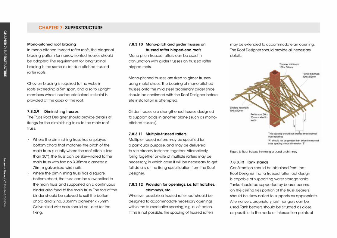
CHAPTER 7: SuPERSTRuCTuRE CH
APTER 7: Su
PERSTRuC
TuRE
Tec
hn
ica
l Ma
nua
l V7: TS-011a
-7.00-180814
Mono-pitched roof bracingIn mono-pitched trussed rafter roofs, the diagonal
bracing pattern for narrow-fronted houses should
be adopted. The requirement for longitudinal
bracing is the same as for duo-pitched trussed
rafter roofs.
Chevron bracing is required to the webs in
roofs exceeding a 5m span, and also to upright
members where inadequate lateral restraint is
provided at the apex of the roof.
7.8.3.9 Diminishing trussesThe Truss Roof Designer should provide details of
fixings for the diminishing truss to the main roof
truss.
• Where the diminishing truss has a splayed
bottom chord that matches the pitch of the
main truss (usually where the roof pitch is less
than 30º), the truss can be skew-nailed to the
main truss with two no 3.35mm diameter x
75mm galvanised wire nails.
• Where the diminishing truss has a square
bottom chord, the truss can be skew-nailed to
the main truss and supported on a continuous
binder also fixed to the main truss. The top of the
binder should be splayed to suit the bottom
chord and; 2 no. 3.35mm diameter x 75mm.
Galvanised wire nails should be used for the
fixing.
7.8.3.10 Mono-pitch and girder trusses on trussed rafter hipped-end roofsMono-pitch trussed rafters can be used in
conjunction with girder trusses on trussed rafter
hipped roofs.
Mono-pitched trusses are fixed to girder trusses
using metal shoes. The bearing of mono-pitched
trusses onto the mild steel proprietary girder shoe
should be confirmed with the Roof Designer before
site installation is attempted.
Girder trusses are strengthened trusses designed
to support loads in another plane (such as mono-
pitched trusses).
7.8.3.11 Multiple-trussed raftersMultiple-trussed rafters may be specified for
a particular purpose, and may be delivered
to site already fastened together. Alternatively,
fixing together on-site of multiple rafters may be
necessary, in which case it will be necessary to get
full details of the fixing specification from the Roof
Designer.
7.8.3.12 Provision for openings, i.e. loft hatches, chimneys, etc.Wherever possible, a trussed rafter roof should be
designed to accommodate necessary openings
within the trussed rafter spacing, e.g. a loft hatch.
If this is not possible, the spacing of trussed rafters
may be extended to accommodate an opening.
The Roof Designer should provide all necessary
details.
7.8.3.13 Tank standsConfirmation should be obtained from the
Roof Designer that a trussed rafter roof design
is capable of supporting water storage tanks.
Tanks should be supported by bearer beams,
on the ceiling ties portion of the truss. Bearers
should be skew-nailed to supports as appropriate.
Alternatively, proprietary joist hangers can be
used. Tank bearers should be situated as close
as possible to the node or intersection points of
Figure 8: Roof trusses trimming around a chimney
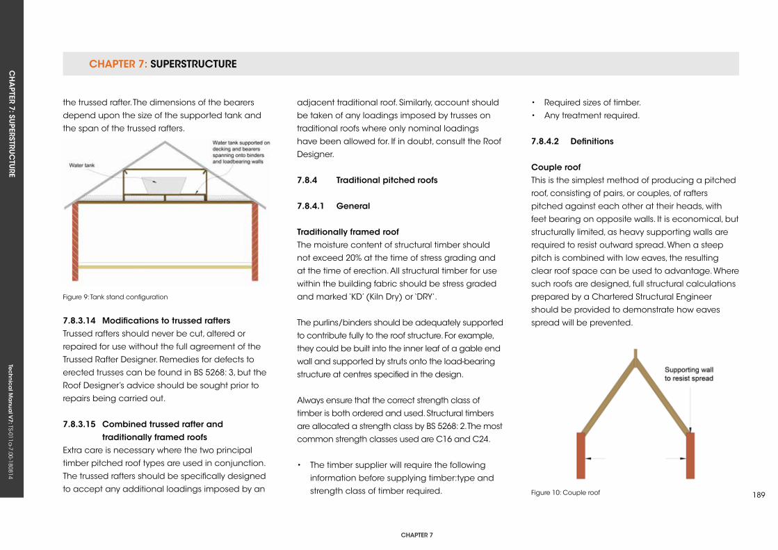
CHAPTER 7: SuPERSTRuCTuRECH
APTER 7: Su
PERSTRuC
TuRE
Tec
hn
ica
l Ma
nua
l V7: TS-011a
-7.00-180814
CHAPTER 7
189
the trussed rafter. The dimensions of the bearers
depend upon the size of the supported tank and
the span of the trussed rafters.
Figure 9: Tank stand configuration
Figure 10: Couple roof
7.8.3.14 Modifications to trussed raftersTrussed rafters should never be cut, altered or
repaired for use without the full agreement of the
Trussed Rafter Designer. Remedies for defects to
erected trusses can be found in BS 5268: 3, but the
Roof Designer’s advice should be sought prior to
repairs being carried out.
7.8.3.15 Combined trussed rafter and traditionally framed roofsExtra care is necessary where the two principal
timber pitched roof types are used in conjunction.
The trussed rafters should be specifically designed
to accept any additional loadings imposed by an
adjacent traditional roof. Similarly, account should
be taken of any loadings imposed by trusses on
traditional roofs where only nominal loadings
have been allowed for. If in doubt, consult the Roof
Designer.
7.8.4 Traditional pitched roofs
7.8.4.1 general
Traditionally framed roof The moisture content of structural timber should
not exceed 20% at the time of stress grading and
at the time of erection. All structural timber for use
within the building fabric should be stress graded
and marked ‘kD’ (kiln Dry) or ‘DRy’.
The purlins/binders should be adequately supported
to contribute fully to the roof structure. For example,
they could be built into the inner leaf of a gable end
wall and supported by struts onto the load-bearing
structure at centres specified in the design.
Always ensure that the correct strength class of
timber is both ordered and used. Structural timbers
are allocated a strength class by BS 5268: 2. The most
common strength classes used are C16 and C24.
• The timber supplier will require the following
information before supplying timber:type and
strength class of timber required.
• Required sizes of timber.
• Any treatment required.
7.8.4.2 Definitions
Couple roofThis is the simplest method of producing a pitched
roof, consisting of pairs, or couples, of rafters
pitched against each other at their heads, with
feet bearing on opposite walls. It is economical, but
structurally limited, as heavy supporting walls are
required to resist outward spread. When a steep
pitch is combined with low eaves, the resulting
clear roof space can be used to advantage. Where
such roofs are designed, full structural calculations
prepared by a Chartered Structural Engineer
should be provided to demonstrate how eaves
spread will be prevented.
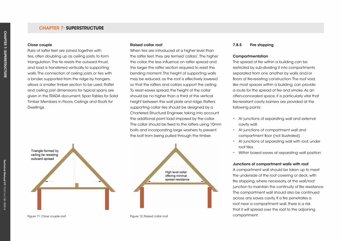
CHAPTER 7: SuPERSTRuCTuRE CH
APTER 7: Su
PERSTRuC
TuRE
Tec
hn
ica
l Ma
nua
l V7: TS-011a
-7.00-180814
Close couplePairs of rafter feet are joined together with
ties, often doubling up as ceiling joists, to form
triangulation. The tie resists the outward thrust,
and load is transferred vertically to supporting
walls. The connection of ceiling joists or ties with
a binder, supported from the ridge by hangers,
allows a smaller timber section to be used. Rafter
and ceiling joist dimensions for typical spans are
given in the TRADA document, Span Tables for Solid
Timber Members in Floors, Ceilings and Roofs for
Dwellings.
raised collar roofWhen ties are introduced at a higher level than
the rafter feet, they are termed ‘collars’. The higher
the collar, the less influence on rafter spread and
the larger the rafter section required to resist the
bending moment. The height of supporting walls
may be reduced, as the roof is effectively lowered
so that the rafters and collars support the ceiling.
To resist eaves spread, the height of the collar
should be no higher than a third of the vertical
height between the wall plate and ridge. Rafters
supporting collar ties should be designed by a
Chartered Structural Engineer, taking into account
the additional point load imposed by the collar.
The collar should be fixed to the rafters using 10mm
bolts and incorporating large washers to prevent
the bolt from being pulled through the timber.
Figure 11: Close couple roof Figure 12: Raised collar roof
7.8.5 fire stopping
CompartmentationThe spread of fire within a building can be
restricted by sub-dividing it into compartments
separated from one another by walls and/or
floors of fire-resisting construction. The roof void,
like most spaces within a building, can provide
a route for the spread of fire and smoke. As an
often-concealed space, it is particularly vital that
fire-resistant cavity barriers are provided at the
following points:
• At junctions of separating wall and external
cavity wall.
• At junctions of compartment wall and
compartment floor (not illustrated).
• At junctions of separating wall with roof, under
roof tiles.
• Within boxed eaves at separating wall position.
Junctions of compartment walls with roofA compartment wall should be taken up to meet
the underside of the roof covering or deck, with
fire stopping, where necessary, at the wall/roof
junction to maintain the continuity of fire resistance.
The compartment wall should also be continued
across any eaves cavity. If a fire penetrates a
roof near a compartment wall, there is a risk
that it will spread over the roof to the adjoining
compartment.
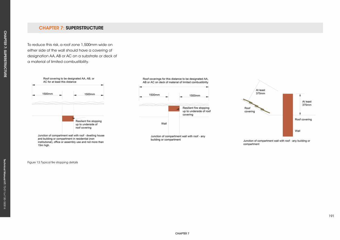
CHAPTER 7: SuPERSTRuCTuRECH
APTER 7: Su
PERSTRuC
TuRE
Tec
hn
ica
l Ma
nua
l V7: TS-011a
-7.00-180814
CHAPTER 7
191
To reduce this risk, a roof zone 1,500mm wide on
either side of the wall should have a covering of
designation AA, AB or AC on a substrate or deck of
a material of limited combustibility.
Figure 13: Typical fire stopping details

Tec
hn
ica
l Ma
nua
l V6: TS-011a
-6.00-010413Te
ch
nic
al M
anu
al V
7: TS-011a-7.00-180814
FUNCTIONAL REQUIREMENTS
7.9 roof Coverings - TrADiTionAL sLATe AnD TiLes
Workmanshipi. All workmanship must be within the tolerances defined in Chapter 1
of this Manual.
ii. All work is to be carried out by a technically competent person in
a workmanlike manner.
iii. Certification is required for any work completed by an approved
installer.
Materialsi. All materials should be stored correctly in a manner that will not cause
damage or deterioration of the product.
ii. All materials, products and building systems shall be appropriate and
suitable for their intended purpose.
iii. The structure shall, unless specifically agreed otherwise with the
Warranty provider, have a life of not less than 60 years. Individual
components and assemblies, not integral to the structure, may have
a lesser durability, but not in any circumstances less than 15 years.
Designi. The design and specifications shall provide a clear indication of the
design intent and demonstrate a satisfactory level of performance.
ii. Roof coverings must prevent any external moisture from passing into
the internal environment of the dwelling.
iii. Structural elements outside the parameters of regional Approved
Documents A must be supported by structural calculations provided
by a suitably qualified expert.
iv. The materials, design and construction must meet the relevant
Building Regulations, British Standards, Eurocodes and other statutory
requirements.
CHAPTER 7: SuPERSTRuCTuRECH
APTER 7: Su
PERSTRuC
TuRE
Tec
hn
ica
l Ma
nua
l V7: TS-011a
-7.00-180814
CHAPTER 7
193
7.9.1 Legislation and planningTiled and pitched roof coverings should be in
accordance with the relevant Building Regulations.
The principal British Standards relevant to this
document are:
• BS 5534 Code of Practice for slating and tiling
(including shingles). This gives
recommendations for the design, materials,
application, installation and performance
of slates and tiles (BS 5534 should be read in
conjunction with BS 8000-6).
• BS 8000-6 Workmanship on building sites.
Code of Practice for slating and tiling of roofs
and claddings. This applies to the laying and
fixing of clay and concrete tiles, natural and
fibre cement slates and their associated fixings
and accessories.
• BS 5250 Control of condensation in buildings.
This describes the causes and effects of surface
and interstitial condensation in buildings,
and gives recommendations for control of
condensation in roofs.
To ensure safe working practices during construction,
the Designer should consider relevant safety
regulations. These include the Construction (Design
and Management) Regulations and the Health and
Safety Executive’s Approved Code of Practice for
Management of Health and Safety at Work.
Certain advisory bodies, such as the Loss
Prevention Council, Building Research
Establishment Ltd (BRE) and Timber Research
and Development Association (TRADA), also
produce recommendations and guidance on roof
construction.
7.9.2 Weather exposure
7.9.2.1 rain and snowThe roof of the building shall adequately protect
the building and people who use the building
from harmful effects caused by precipitation and
wind-driven spray. Roofs are required to resist the
penetration of precipitation (rainfall) to the inside
of the building, thereby preventing damage to any
part of the building where it might be carried.
Most pitched roofs keep the rain and snow out of
the building and give a satisfactory performance.
However, it is acknowledged that similar roofs
built to the same design and using identical
roof materials, but in different locations, may not
necessarily provide the same level of assurance
since they will be subject to different weather
conditions and exposure.
exposure to driving rainThe uk has a high risk of severe driving rain, and
even in some sheltered locations may be subject
to high levels of deluge rainfall. BS 5534 defines two
categories of exposure, based on the driving rain
data given in BS 8104 and BR 262, and should be
used for buildings up to 12m in height. For buildings
over 12m in height, the influence of increased wind
speeds should be taken into account using BS EN
1991-1-4: 2005+A1.
Performance of tiles and slatesRain penetration of the roof covering is dependent
on a combination of the rainfall rate, wind speed
and the ability of the roof tile or slate to resist the
ingress of snow and rain water. The Designer should
therefore be aware of the various means by which
rain and snow can, under certain conditions,
penetrate the roof covering.
These include:
• Capillary action and rain water creep.
• Raindrop bounce and negative pressure rain
suction.
• Driving rain, deluge rain and flooding.
• Surcharging of rain water over laps on
long-rafter roofs.
• Wind-driven snow.
CHAPTER 7: SuPERSTRuCTuRE CH
APTER 7: Su
PERSTRuC
TuRE
Tec
hn
ica
l Ma
nua
l V7: TS-011a
-7.00-180814
roof pitchWhen determining the pitch, head-lap and/or
side-lap of a tile or slate, the roof pitch is taken to
be equal to the rafter pitch. Hence, all references
to pitch refer to the rafter pitch, with the laid angle
of the roof tile or slate always being less than roof
pitch.
The actual pitch of a slate or tile should be
determined in accordance with the following
guidelines:
• Tile/slate to rafter pitch angles.
• Plain tiles: 7° less than rafter pitch.
• Interlocking single-lap tiles and slates: 5° less
than rafter pitch.
• Double-lap fibre cement slates: 1.25° less than
rafter pitch.
If the design rafter pitch is less than the minimum
recommended rafter pitch for the particular tile
or slate, then they can be considered as having
an aesthetic function only. In such cases, the true
weather proofing of the roof system must rely on
a fully supported waterproof membrane with an
uninterrupted drainage path between counter
battens to the eaves gutter.
7.9.2.2 Wind
Design for wind loadingWhen considering the wind loading on the roof
covering, Designers should consult BS 5534. This
provides calculation methods to assess the wind
load on each tile or slate as a uniformly distributed
load, and also takes into account the porosity
of the tiles or slates and the effectiveness of the
substrate (boarding or sarking), and/or underlay
shielding, when calculating wind uplift loads.
The standard method in BS EN 1991-1-4: 2005+A1
Eurocode 1. Actions on structures. General actions.
Wind actions should be used to determine the
basic wind speed of the site, which is then used to
calculate the effective wind speed and dynamic
wind pressure on the roof by applying a series of
factors to account for terrain, topography, building
height and length, etc.
Control of internal pressureThe total wind force on a roof is dependent on
the pressure differential between the inner and
outer faces of the roof covering. Such pressures
are significantly reduced by the use of underlay or
boarding beneath tiling or slating. Its contribution
towards shielding the underside of the tiles or slates
from the full transmission of internal pressures means
the underlay is required to have an adequate
tensile strength for the specific application. The
tensile strength of the underlay, its air permeability
factor and the withdrawal resistance of batten nail
fixings are therefore important when determining the
overall resistance to wind uplift of the roof system.
ridges, hips, verges and valleysThe use of mortar for the bedding of concrete
or clay ridge and ridged hip tiles on concrete or
clay tiles or fibre cement slates; does not provide
sufficient tensile bond strength to resist wind uplift
as it can be affected by a number of factors,
such as wind loadings, mix of mortar, design and
movement of the roof structure. The use of mortar
bedding should be supplemented by suitable
mechanical fixings to ensure the component is
mechanically fixed.
note: Dry fix ridge and hip systems are available to
provide full mechanical fixing of all ridge and hip
tiles to meet BS 5534 recommendations.
Aircraft vorticesRoofs near airports can experience high local
wind load forces due to air vortices created by
certain aircraft when taking off and landing, which
may be greater than the wind loads calculated
to BS 5534. Designers should seek advice from
the Airport Authority Planning Department when
designing roof fixings in these locations, and refer
to the guidance contained in BRE Digest 467 Slate
and tile roofs: avoiding damage from aircraft wake
vortices.
CHAPTER 7: SuPERSTRuCTuRECH
APTER 7: Su
PERSTRuC
TuRE
Tec
hn
ica
l Ma
nua
l V7: TS-011a
-7.00-180814
CHAPTER 7
195
Calculating the fixing specificationThe procedures for calculating the wind loads
and determining the fixing specification for tiles
and slates in accordance with BS EN 1991-1-4:
2005+A1 and BS 5534 are complex to undertake.
Designers are advised to obtain a full roofing
fixing specification either from the slate or tile
manufacturer or by reference to the Zonal Fixing
Method tables, which provide a conservative
interpretation of the fixing requirements in BS 5534.
Zonal fixing methodThe zonal method is a means of obtaining a fixing
specification for roof tiles and is a simplification
of the calculations defined in BS 5534 Code of
Practice for slating and tiling (including shingles)
and BS EN 1991-1-4: 2005+A1 Eurocode 1. Actions
on structures. General actions. Wind actions. The
assumptions made in the simplification process
may produce a specification with more or stronger
fixings than those required if the full BS 5534
calculation is used.
Zonal fixing specification single lap tiles Double lap tiles
A No fixings required
Refer to manufacturer
B
Each tile once nailed (right hand nail hole – flat tiles)
CEach tile twice nailed (flat tiles only)
D Each tile clipped
EEach tile once nailed and clipped
FEach tile twice nailed and clipped
notes:
(1) The manufacturer may also specify the use of improved nails for fixing tiles, e.g., ring shank nails. Where these are required, the Zonal fixing specification letter will be marked with an asterisk, e.g., C*.(2) Manufacturers may define additional fixing specifications to those in the table and assign fixing specification letters from ‘G’ onwards. (3) In some cases, the manufacturer may specify a ‘proprietary fixing system’ and this will be marked ‘PS’. The manufacturer should be contacted for details of the requirements for this fixing method.
7.9.3 Condensation and ventilation
7.9.3.1 statutory requirementsThe roof should be designed and constructed in
accordance with clause 8.4 of BS 5250 and BS
EN ISO 13788. Detailed information on methods
to control harmful condensation is provided in BS
5250 Code of Practice for control of condensation
in buildings, Section 8.4 Roofs.
Prevention of condensation in roof voids is best
achieved through the provision of natural air
ventilation. BS 5250 states that the Designer should
take account of the following moisture sources in
buildings:
• Water incorporated during the construction
process (including precipitation).
• Precipitation after construction.
• Water vapour arising from the occupants and
their activities.
• Temporary condensation occurring when cold
weather conditions are followed by warm,
humid weather.
sealed ceilingsBS 9250 emphasises the importance of well-sealed
ceilings as a means of curbing the transfer of
moisture into a roof space by means of
moisture-laden air.
Table 1: Zonal fixing specification
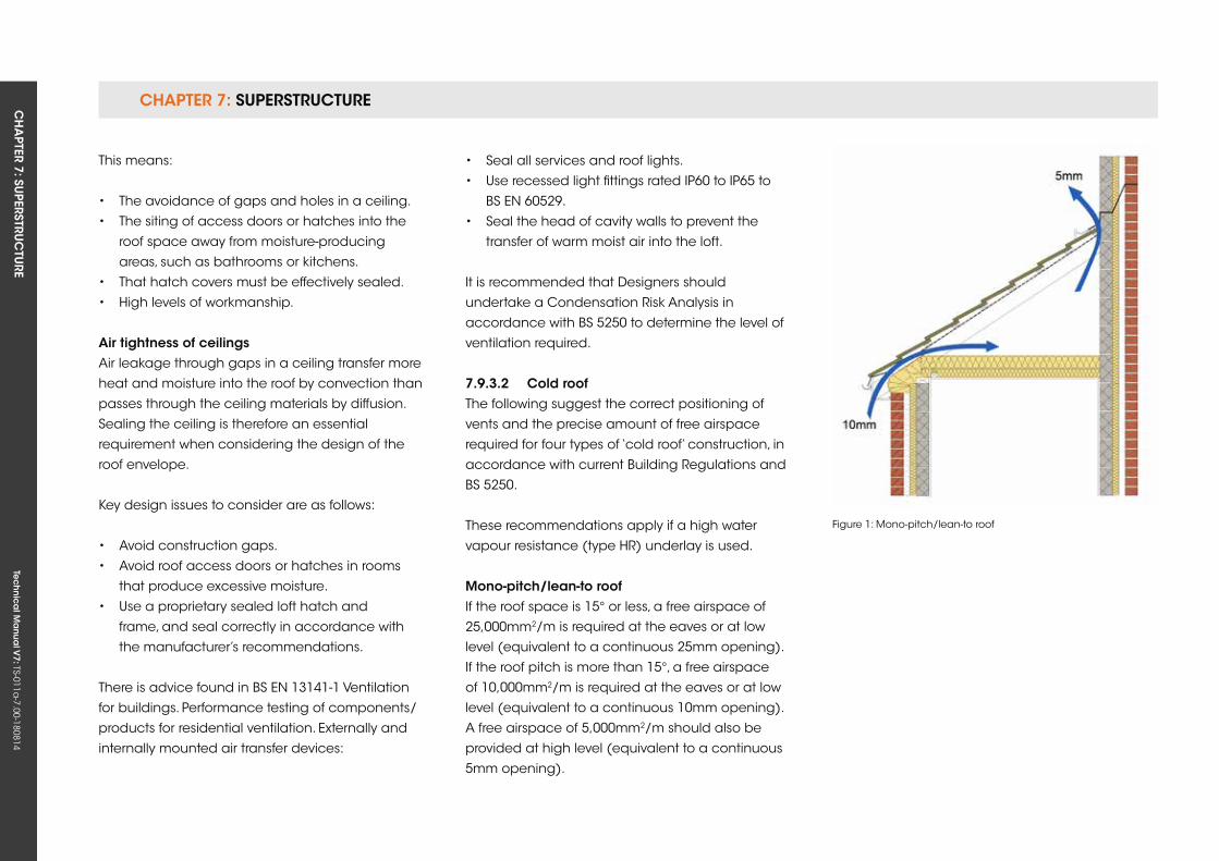
CHAPTER 7: SuPERSTRuCTuRE CH
APTER 7: Su
PERSTRuC
TuRE
Tec
hn
ica
l Ma
nua
l V7: TS-011a
-7.00-180814
This means:
• The avoidance of gaps and holes in a ceiling.
• The siting of access doors or hatches into the
roof space away from moisture-producing
areas, such as bathrooms or kitchens.
• That hatch covers must be effectively sealed.
• High levels of workmanship.
Air tightness of ceilingsAir leakage through gaps in a ceiling transfer more
heat and moisture into the roof by convection than
passes through the ceiling materials by diffusion.
Sealing the ceiling is therefore an essential
requirement when considering the design of the
roof envelope.
key design issues to consider are as follows:
• Avoid construction gaps.
• Avoid roof access doors or hatches in rooms
that produce excessive moisture.
• use a proprietary sealed loft hatch and
frame, and seal correctly in accordance with
the manufacturer’s recommendations.
There is advice found in BS EN 13141-1 Ventilation
for buildings. Performance testing of components/
products for residential ventilation. Externally and
internally mounted air transfer devices:
• Seal all services and roof lights.
• use recessed light fittings rated IP60 to IP65 to
BS EN 60529.
• Seal the head of cavity walls to prevent the
transfer of warm moist air into the loft.
It is recommended that Designers should
undertake a Condensation Risk Analysis in
accordance with BS 5250 to determine the level of
ventilation required.
7.9.3.2 Cold roof The following suggest the correct positioning of
vents and the precise amount of free airspace
required for four types of ‘cold roof’ construction, in
accordance with current Building Regulations and
BS 5250.
These recommendations apply if a high water
vapour resistance (type HR) underlay is used.
Mono-pitch/lean-to roof If the roof space is 15° or less, a free airspace of
25,000mm2/m is required at the eaves or at low
level (equivalent to a continuous 25mm opening).
If the roof pitch is more than 15°, a free airspace
of 10,000mm2/m is required at the eaves or at low
level (equivalent to a continuous 10mm opening).
A free airspace of 5,000mm2/m should also be
provided at high level (equivalent to a continuous
5mm opening).
Figure 1: Mono-pitch/lean-to roof
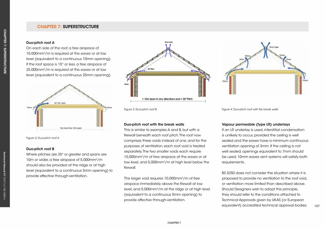
CHAPTER 7: SuPERSTRuCTuRECH
APTER 7: Su
PERSTRuC
TuRE
Tec
hn
ica
l Ma
nua
l V7: TS-011a
-7.00-180814
CHAPTER 7
197
Duo-pitch roof AOn each side of the roof, a free airspace of
10,000mm2/m is required at the eaves or at low
level (equivalent to a continuous 10mm opening).
If the roof space is 15° or less, a free airspace of
25,000mm2/m is required at the eaves or at low
level (equivalent to a continuous 25mm opening).
Figure 2: Duo-pitch roof A
Figure 3: Duo-pitch roof B Figure 4: Duo-pitch roof with fire break walls
Duo-pitch roof BWhere pitches are 35° or greater and spans are
10m or wider, a free airspace of 5,000mm2/m
should also be provided at the ridge or at high
level (equivalent to a continuous 5mm opening) to
provide effective through-ventilation.
Duo-pitch roof with fire break wallsThis is similar to examples A and B, but with a
firewall beneath each roof pitch. The roof now
comprises three voids instead of one, and for the
purposes of ventilation, each roof void is treated
separately. The two smaller voids each require
10,000mm2/m of free airspace at the eaves or at
low level, and 5,000mm2/m at high level below the
firewall.
The larger void requires 10,000mm2/m of free
airspace immediately above the firewall at low
level, and 5,000mm2/m at the ridge or at high level
(equivalent to a continuous 5mm opening) to
provide effective through-ventilation.
vapour permeable (type Lr) underlaysIf an LR underlay is used, interstitial condensation
is unlikely to occur, provided the ceiling is well
sealed and the eaves have a minimum continuous
ventilation opening of 3mm. If the ceiling is not
well sealed, openings equivalent to 7mm should
be used; 10mm eaves vent systems will satisfy both
requirements.
BS 5250 does not consider the situation where it is
proposed to provide no ventilation to the roof void,
or ventilation more limited than described above.
Should Designers wish to adopt this principle,
they should refer to the conditions attached to
Technical Approvals given by ukAS (or European
equivalent) accredited technical approval bodies.
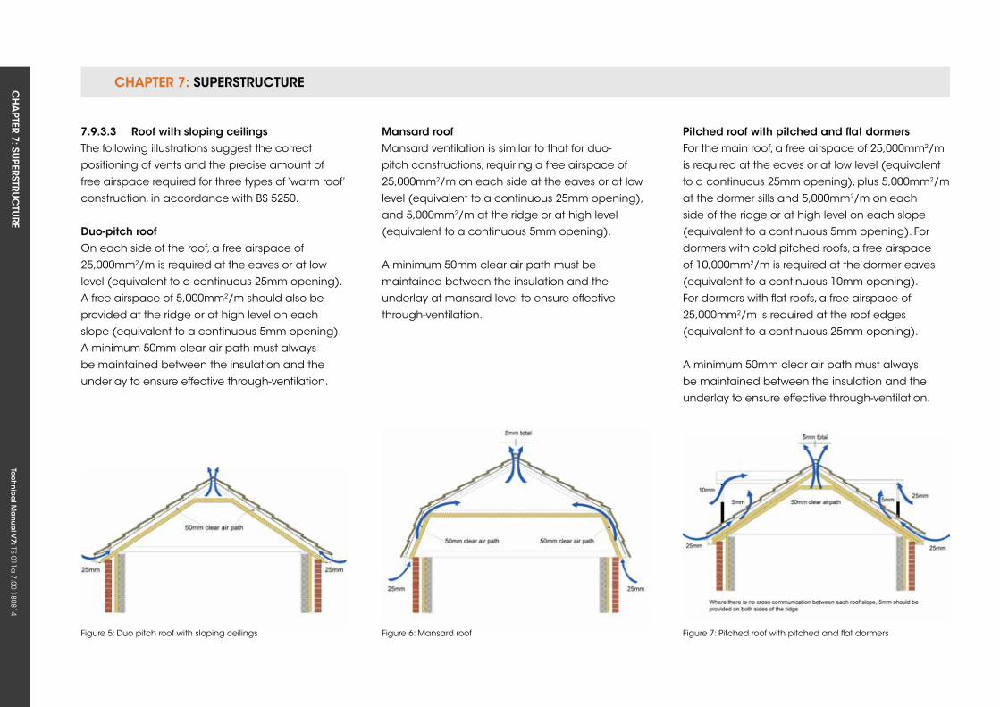
CHAPTER 7: SuPERSTRuCTuRE CH
APTER 7: Su
PERSTRuC
TuRE
Tec
hn
ica
l Ma
nua
l V7: TS-011a
-7.00-180814
7.9.3.3 roof with sloping ceilings The following illustrations suggest the correct
positioning of vents and the precise amount of
free airspace required for three types of ‘warm roof’
construction, in accordance with BS 5250.
Duo-pitch roofOn each side of the roof, a free airspace of
25,000mm2/m is required at the eaves or at low
level (equivalent to a continuous 25mm opening).
A free airspace of 5,000mm2/m should also be
provided at the ridge or at high level on each
slope (equivalent to a continuous 5mm opening).
A minimum 50mm clear air path must always
be maintained between the insulation and the
underlay to ensure effective through-ventilation.
Mansard roofMansard ventilation is similar to that for duo-
pitch constructions, requiring a free airspace of
25,000mm2/m on each side at the eaves or at low
level (equivalent to a continuous 25mm opening),
and 5,000mm2/m at the ridge or at high level
(equivalent to a continuous 5mm opening).
A minimum 50mm clear air path must be
maintained between the insulation and the
underlay at mansard level to ensure effective
through-ventilation.
Figure 5: Duo pitch roof with sloping ceilings Figure 6: Mansard roof
Pitched roof with pitched and flat dormers For the main roof, a free airspace of 25,000mm2/m
is required at the eaves or at low level (equivalent
to a continuous 25mm opening), plus 5,000mm2/m
at the dormer sills and 5,000mm2/m on each
side of the ridge or at high level on each slope
(equivalent to a continuous 5mm opening). For
dormers with cold pitched roofs, a free airspace
of 10,000mm2/m is required at the dormer eaves
(equivalent to a continuous 10mm opening).
For dormers with flat roofs, a free airspace of
25,000mm2/m is required at the roof edges
(equivalent to a continuous 25mm opening).
A minimum 50mm clear air path must always
be maintained between the insulation and the
underlay to ensure effective through-ventilation.
Figure 7: Pitched roof with pitched and flat dormers
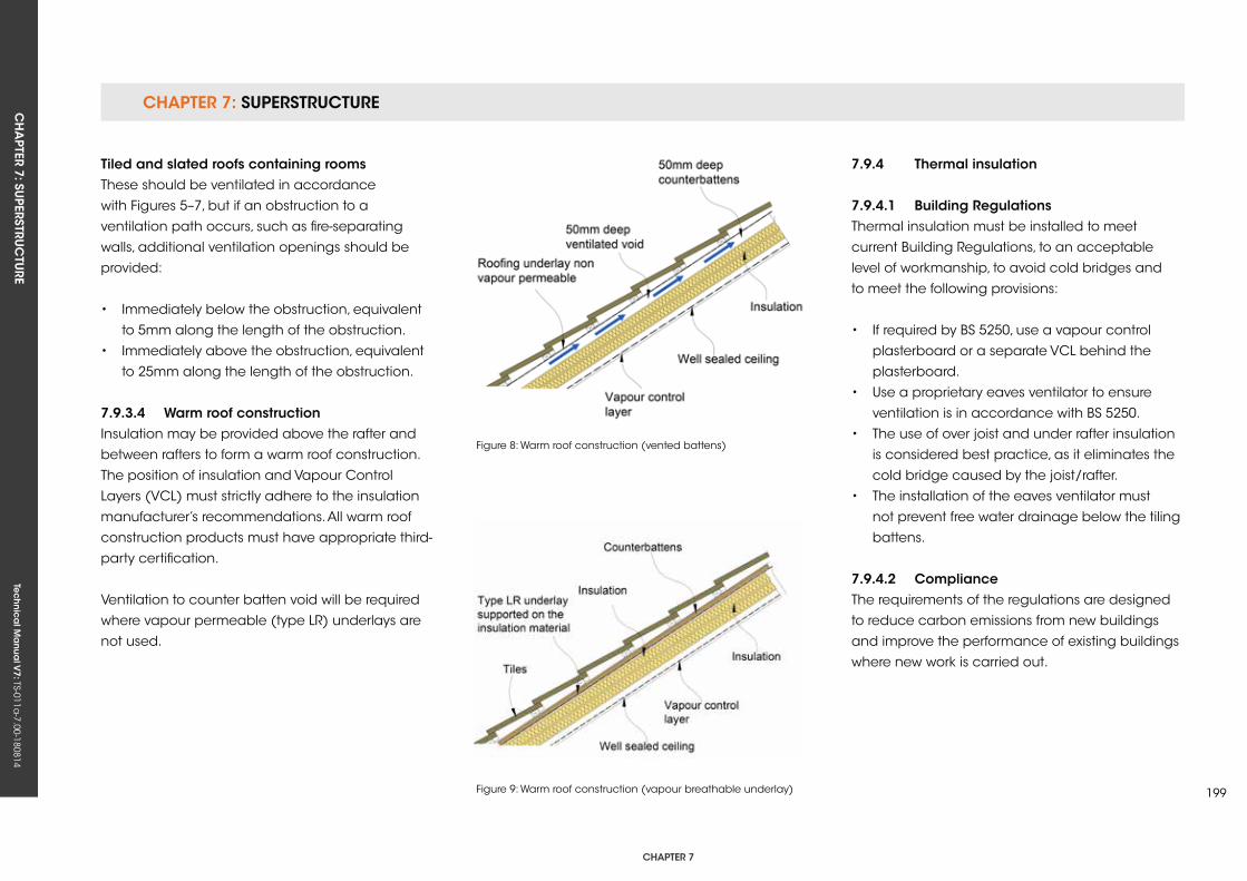
CHAPTER 7: SuPERSTRuCTuRECH
APTER 7: Su
PERSTRuC
TuRE
Tec
hn
ica
l Ma
nua
l V7: TS-011a
-7.00-180814
CHAPTER 7
199
Tiled and slated roofs containing rooms These should be ventilated in accordance
with Figures 5–7, but if an obstruction to a
ventilation path occurs, such as fire-separating
walls, additional ventilation openings should be
provided:
• Immediately below the obstruction, equivalent
to 5mm along the length of the obstruction.
• Immediately above the obstruction, equivalent
to 25mm along the length of the obstruction.
7.9.3.4 Warm roof constructionInsulation may be provided above the rafter and
between rafters to form a warm roof construction.
The position of insulation and Vapour Control
Layers (VCL) must strictly adhere to the insulation
manufacturer’s recommendations. All warm roof
construction products must have appropriate third-
party certification.
Ventilation to counter batten void will be required
where vapour permeable (type LR) underlays are
not used.
Figure 8: Warm roof construction (vented battens)
Figure 9: Warm roof construction (vapour breathable underlay)
7.9.4 Thermal insulation
7.9.4.1 Building regulationsThermal insulation must be installed to meet
current Building Regulations, to an acceptable
level of workmanship, to avoid cold bridges and
to meet the following provisions:
• If required by BS 5250, use a vapour control
plasterboard or a separate VCL behind the
plasterboard.
• use a proprietary eaves ventilator to ensure
ventilation is in accordance with BS 5250.
• The use of over joist and under rafter insulation
is considered best practice, as it eliminates the
cold bridge caused by the joist/rafter.
• The installation of the eaves ventilator must
not prevent free water drainage below the tiling
battens.
7.9.4.2 ComplianceThe requirements of the regulations are designed
to reduce carbon emissions from new buildings
and improve the performance of existing buildings
where new work is carried out.
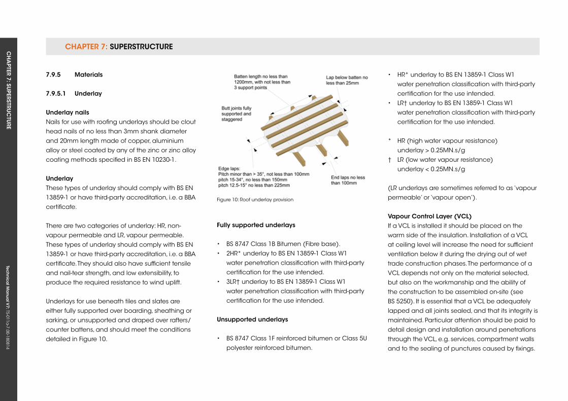
CHAPTER 7: SuPERSTRuCTuRE CH
APTER 7: Su
PERSTRuC
TuRE
Tec
hn
ica
l Ma
nua
l V7: TS-011a
-7.00-180814
7.9.5 Materials
7.9.5.1 underlay
underlay nailsNails for use with roofing underlays should be clout
head nails of no less than 3mm shank diameter
and 20mm length made of copper, aluminium
alloy or steel coated by any of the zinc or zinc alloy
coating methods specified in BS EN 10230-1.
underlayThese types of underlay should comply with BS EN
13859-1 or have third-party accreditation, i.e. a BBA
certificate.
There are two categories of underlay: HR, non-
vapour permeable and LR, vapour permeable.
These types of underlay should comply with BS EN
13859-1 or have third-party accreditation, i.e. a BBA
certificate. They should also have sufficient tensile
and nail-tear strength, and low extensibility, to
produce the required resistance to wind uplift.
underlays for use beneath tiles and slates are
either fully supported over boarding, sheathing or
sarking, or unsupported and draped over rafters/
counter battens, and should meet the conditions
detailed in Figure 10.
fully supported underlays
• BS 8747 Class 1B Bitumen (Fibre base).
• 2HR* underlay to BS EN 13859-1 Class W1
water penetration classification with third-party
certification for the use intended.
• 3LR† underlay to BS EN 13859-1 Class W1
water penetration classification with third-party
certification for the use intended.
unsupported underlays
• BS 8747 Class 1F reinforced bitumen or Class 5u
polyester reinforced bitumen.
Figure 10: Roof underlay provision
• HR* underlay to BS EN 13859-1 Class W1
water penetration classification with third-party
certification for the use intended.
• LR† underlay to BS EN 13859-1 Class W1
water penetration classification with third-party
certification for the use intended.
* HR (high water vapour resistance)
underlay > 0.25MN.s/g
† LR (low water vapour resistance)
underlay < 0.25MN.s/g
(LR underlays are sometimes referred to as ‘vapour
permeable’ or ‘vapour open’).
vapour Control Layer (vCL)If a VCL is installed it should be placed on the
warm side of the insulation. Installation of a VCL
at ceiling level will increase the need for sufficient
ventilation below it during the drying out of wet
trade construction phases. The performance of a
VCL depends not only on the material selected,
but also on the workmanship and the ability of
the construction to be assembled on-site (see
BS 5250). It is essential that a VCL be adequately
lapped and all joints sealed, and that its integrity is
maintained. Particular attention should be paid to
detail design and installation around penetrations
through the VCL, e.g. services, compartment walls
and to the sealing of punctures caused by fixings.
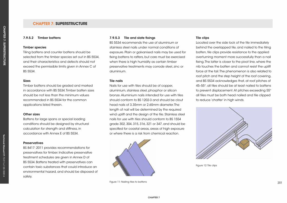
CHAPTER 7: SuPERSTRuCTuRECH
APTER 7: Su
PERSTRuC
TuRE
Tec
hn
ica
l Ma
nua
l V7: TS-011a
-7.00-180814
CHAPTER 7
201
7.9.5.2 Timber battens
Timber speciesTiling battens and counter battens should be
selected from the timber species set out in BS 5534,
and their characteristics and defects should not
exceed the permissible limits given in Annex C of
BS 5534.
sizesTimber battens should be graded and marked
in accordance with BS 5534. Timber batten sizes
should be not less than the minimum values
recommended in BS 5534 for the common
applications listed therein.
other sizesBattens for large spans or special loading
conditions should be designed by structural
calculation for strength and stiffness, in
accordance with Annex E of BS 5534.
PreservativesBS 8417: 2011 provides recommendations for
preservatives for timber. Indicative preservative
treatment schedules are given in Annex D of
BS 5534. Battens treated with preservatives can
contain toxic substances that could introduce an
environmental hazard, and should be disposed of
safely.
7.9.5.3 Tile and slate fixingsBS 5534 recommends the use of aluminium or
stainless steel nails under normal conditions of
exposure. Plain or galvanised nails may be used for
fixing battens to rafters, but care must be exercised
when there is high humidity as certain timber
preservative treatments may corrode steel, zinc or
aluminium.
Tile nailsNails for use with tiles should be of copper,
aluminium, stainless steel, phosphor or silicon
bronze. Aluminium nails intended for use with tiles
should conform to BS 1202-3 and should be clout
head nails of 3.35mm or 2.65mm diameter. The
length of nail will be determined by the required
wind uplift and the design of the tile. Stainless steel
nails for use with tiles should conform to BS 1554
grade 302, 304, 315, 316, 321 or 347, and should be
specified for coastal areas, areas of high exposure
or where there is a risk from chemical reaction.
Figure 11: Nailing tiles to battens
Figure 12: Tile clips
Tile clipsLocated over the side lock of the tile immediately
behind the overlapped tile, and nailed to the tiling
batten, tile clips provide resistance to the applied
overturning moment more successfully than a nail
fixing. The latter is closer to the pivot line, where the
nib touches the batten and cannot resist the uplift
force at the tail. The phenomenon is also related to
roof pitch and the step height of the roof covering,
and BS 5534 acknowledges that, at roof pitches of
45–55°, all tiles should be at least nailed to battens
to prevent displacement. At pitches exceeding 55°
all tiles must be both head nailed and tile clipped
to reduce ‘chatter’ in high winds.
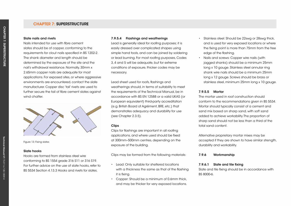
CHAPTER 7: SuPERSTRuCTuRE CH
APTER 7: Su
PERSTRuC
TuRE
Tec
hn
ica
l Ma
nua
l V7: TS-011a
-7.00-180814
slate nails and rivetsNails intended for use with fibre cement
slates should be of copper, conforming to the
requirements for clout nails specified in BS 1202-2.
The shank diameter and length should be
determined by the exposure of the site and the
nail’s withdrawal resistance. Normally, 30mm x
2.65mm copper nails are adequate for most
applications. For exposed sites, or where aggressive
environments are encountered, contact the slate
manufacturer. Copper disc ‘tail’ rivets are used to
further secure the tail of fibre cement slates against
wind chatter.
Figure 13: Fixing slates
slate hooksHooks are formed from stainless steel wire
conforming to BS 1554 grade 316 S11 or 316 S19.
For further advice on the use of slate hooks, refer to
BS 5534 Section 4.13.3 Hooks and rivets for slates.
7.9.5.4 flashings and weatheringsLead is generally ideal for roofing purposes; it is
easily dressed over complicated shapes using
simple hand tools, and can be joined by soldering
or lead burning. For most roofing purposes, Codes
3, 4 and 5 will be adequate, but for extreme
conditions of exposure, thicker codes may be
necessary.
Lead sheet used for roofs, flashings and
weatherings should, in terms of suitability to meet
the requirements of the Technical Manual, be in
accordance with BS EN 12588 or a valid ukAS (or
European equivalent) third-party accreditation
(e.g. British Board of Agrément, BRE, etc.) that
demonstrates adequacy and durability for use
(see Chapter 2.3.5).
Clips Clips for flashings are important in all roofing
applications, and where used should be fixed
at 300mm–500mm centres, depending on the
exposure of the building.
Clips may be formed from the following materials:
• Lead: Only suitable for sheltered locations
with a thickness the same as that of the flashing
it is fixing.
• Copper: Should be a minimum of 0.6mm thick,
and may be thicker for very exposed locations.
• Stainless steel: Should be 22swg or 28swg thick,
and is used for very exposed locations or where
the fixing point is more than 75mm from the free
edge of the flashing.
• Nails and screws: Copper wire nails (with
jagged shanks) should be a minimum 25mm
long x 10 gauge. Stainless steel annular ring
shank wire nails should be a minimum 25mm
long x 12 gauge. Screws should be brass or
stainless steel, minimum 25mm long x 10 gauge.
7.9.5.5 MortarThe mortar used in roof construction should
conform to the recommendations given in BS 5534.
Mortar should typically consist of a cement and
sand mix based on sharp sand, with soft sand
added to achieve workability. The proportion of
sharp sand should not be less than a third of the
total sand content.
Alternative proprietary mortar mixes may be
accepted if they are shown to have similar strength,
durability and workability.
7.9.6 Workmanship
7.9.6.1 slate and tile fixing Slate and tile fixing should be in accordance with
BS 8000-6.
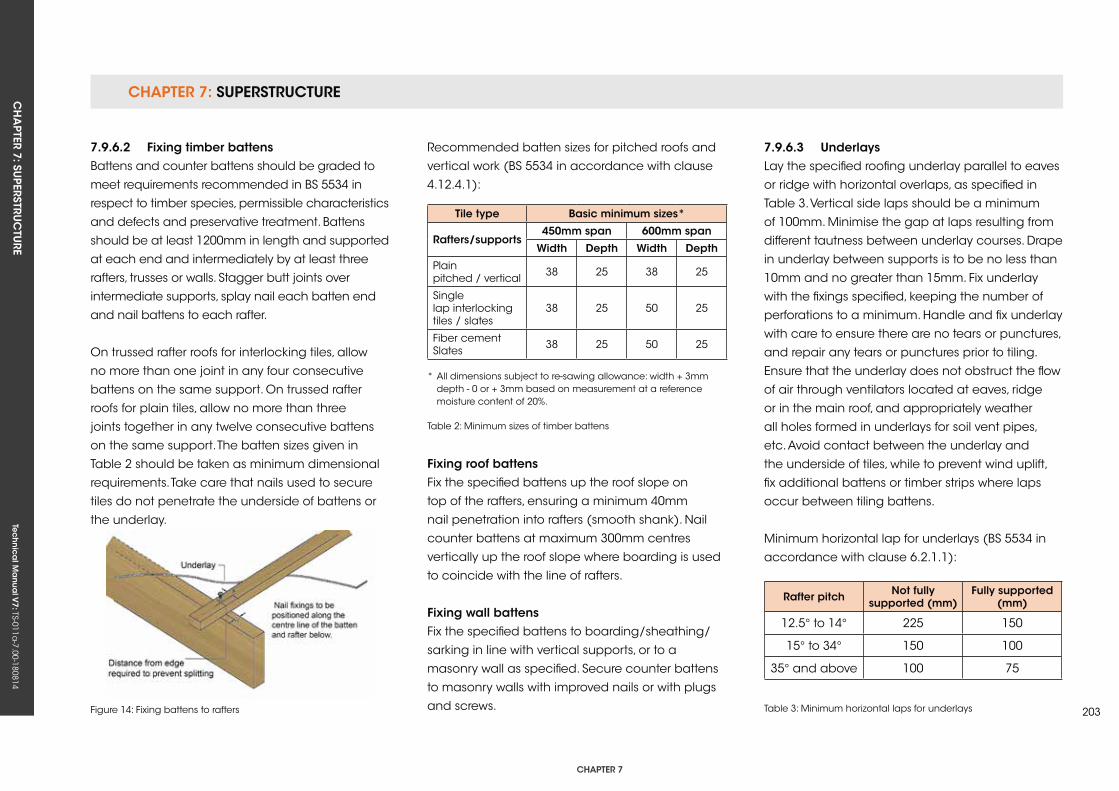
CHAPTER 7: SuPERSTRuCTuRECH
APTER 7: Su
PERSTRuC
TuRE
Tec
hn
ica
l Ma
nua
l V7: TS-011a
-7.00-180814
CHAPTER 7
203
7.9.6.2 fixing timber battensBattens and counter battens should be graded to
meet requirements recommended in BS 5534 in
respect to timber species, permissible characteristics
and defects and preservative treatment. Battens
should be at least 1200mm in length and supported
at each end and intermediately by at least three
rafters, trusses or walls. Stagger butt joints over
intermediate supports, splay nail each batten end
and nail battens to each rafter.
On trussed rafter roofs for interlocking tiles, allow
no more than one joint in any four consecutive
battens on the same support. On trussed rafter
roofs for plain tiles, allow no more than three
joints together in any twelve consecutive battens
on the same support. The batten sizes given in
Table 2 should be taken as minimum dimensional
requirements. Take care that nails used to secure
tiles do not penetrate the underside of battens or
the underlay.
Figure 14: Fixing battens to rafters
Recommended batten sizes for pitched roofs and
vertical work (BS 5534 in accordance with clause
4.12.4.1):
Tile type Basic minimum sizes*
rafters/supports450mm span 600mm span
Width Depth Width Depth
Plainpitched / vertical 38 25 38 25
Single lap interlockingtiles / slates
38 25 50 25
Fiber cementSlates 38 25 50 25
* All dimensions subject to re-sawing allowance: width + 3mm depth - 0 or + 3mm based on measurement at a reference moisture content of 20%.
Table 2: Minimum sizes of timber battens
fixing roof battensFix the specified battens up the roof slope on
top of the rafters, ensuring a minimum 40mm
nail penetration into rafters (smooth shank). Nail
counter battens at maximum 300mm centres
vertically up the roof slope where boarding is used
to coincide with the line of rafters.
fixing wall battensFix the specified battens to boarding/sheathing/
sarking in line with vertical supports, or to a
masonry wall as specified. Secure counter battens
to masonry walls with improved nails or with plugs
and screws.
7.9.6.3 underlaysLay the specified roofing underlay parallel to eaves
or ridge with horizontal overlaps, as specified in
Table 3. Vertical side laps should be a minimum
of 100mm. Minimise the gap at laps resulting from
different tautness between underlay courses. Drape
in underlay between supports is to be no less than
10mm and no greater than 15mm. Fix underlay
with the fixings specified, keeping the number of
perforations to a minimum. Handle and fix underlay
with care to ensure there are no tears or punctures,
and repair any tears or punctures prior to tiling.
Ensure that the underlay does not obstruct the flow
of air through ventilators located at eaves, ridge
or in the main roof, and appropriately weather
all holes formed in underlays for soil vent pipes,
etc. Avoid contact between the underlay and
the underside of tiles, while to prevent wind uplift,
fix additional battens or timber strips where laps
occur between tiling battens.
Minimum horizontal lap for underlays (BS 5534 in
accordance with clause 6.2.1.1):
rafter pitch not fully supported (mm)
fully supported (mm)
12.5° to 14° 225 150
15° to 34° 150 100
35° and above 100 75
Table 3: Minimum horizontal laps for underlays
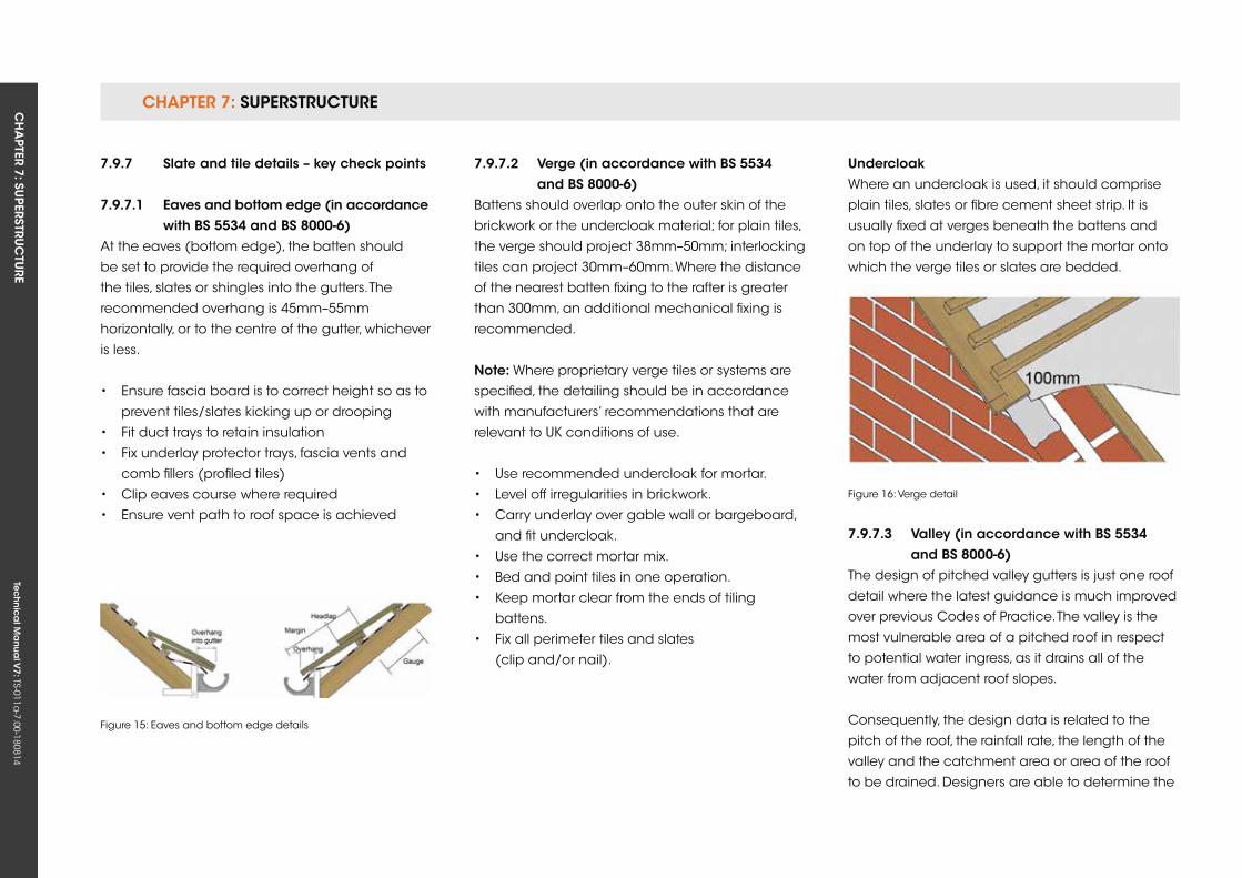
CHAPTER 7: SuPERSTRuCTuRE CH
APTER 7: Su
PERSTRuC
TuRE
Tec
hn
ica
l Ma
nua
l V7: TS-011a
-7.00-180814
7.9.7 slate and tile details – key check points
7.9.7.1 eaves and bottom edge (in accordance with Bs 5534 and Bs 8000-6)At the eaves (bottom edge), the batten should
be set to provide the required overhang of
the tiles, slates or shingles into the gutters. The
recommended overhang is 45mm–55mm
horizontally, or to the centre of the gutter, whichever
is less.
• Ensure fascia board is to correct height so as to
prevent tiles/slates kicking up or drooping
• Fit duct trays to retain insulation
• Fix underlay protector trays, fascia vents and
comb fillers (profiled tiles)
• Clip eaves course where required
• Ensure vent path to roof space is achieved
7.9.7.2 verge (in accordance with Bs 5534 and Bs 8000-6)Battens should overlap onto the outer skin of the
brickwork or the undercloak material; for plain tiles,
the verge should project 38mm–50mm; interlocking
tiles can project 30mm–60mm. Where the distance
of the nearest batten fixing to the rafter is greater
than 300mm, an additional mechanical fixing is
recommended.
note: Where proprietary verge tiles or systems are
specified, the detailing should be in accordance
with manufacturers’ recommendations that are
relevant to uk conditions of use.
• use recommended undercloak for mortar.
• Level off irregularities in brickwork.
• Carry underlay over gable wall or bargeboard,
and fit undercloak.
• use the correct mortar mix.
• Bed and point tiles in one operation.
• keep mortar clear from the ends of tiling
battens.
• Fix all perimeter tiles and slates
(clip and/or nail).
Figure 15: Eaves and bottom edge details
Figure 16: Verge detail
undercloakWhere an undercloak is used, it should comprise
plain tiles, slates or fibre cement sheet strip. It is
usually fixed at verges beneath the battens and
on top of the underlay to support the mortar onto
which the verge tiles or slates are bedded.
7.9.7.3 valley (in accordance with Bs 5534 and Bs 8000-6)The design of pitched valley gutters is just one roof
detail where the latest guidance is much improved
over previous Codes of Practice. The valley is the
most vulnerable area of a pitched roof in respect
to potential water ingress, as it drains all of the
water from adjacent roof slopes.
Consequently, the design data is related to the
pitch of the roof, the rainfall rate, the length of the
valley and the catchment area or area of the roof
to be drained. Designers are able to determine the
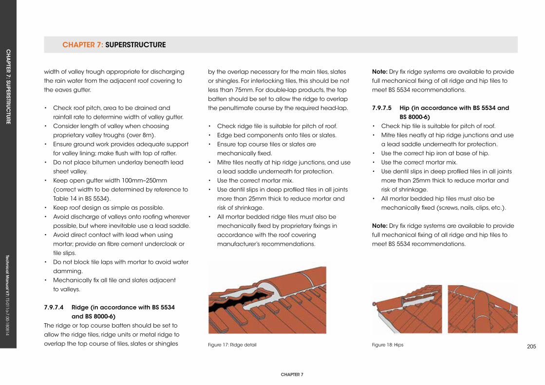
CHAPTER 7: SuPERSTRuCTuRECH
APTER 7: Su
PERSTRuC
TuRE
Tec
hn
ica
l Ma
nua
l V7: TS-011a
-7.00-180814
CHAPTER 7
205
width of valley trough appropriate for discharging
the rain water from the adjacent roof covering to
the eaves gutter.
• Check roof pitch, area to be drained and
rainfall rate to determine width of valley gutter.
• Consider length of valley when choosing
proprietary valley troughs (over 8m).
• Ensure ground work provides adequate support
for valley lining; make flush with top of rafter.
• Do not place bitumen underlay beneath lead
sheet valley.
• keep open gutter width 100mm–250mm
(correct width to be determined by reference to
Table 14 in BS 5534).
• keep roof design as simple as possible.
• Avoid discharge of valleys onto roofing wherever
possible, but where inevitable use a lead saddle.
• Avoid direct contact with lead when using
mortar; provide an fibre cement undercloak or
tile slips.
• Do not block tile laps with mortar to avoid water
damming.
• Mechanically fix all tile and slates adjacent
to valleys.
7.9.7.4 ridge (in accordance with Bs 5534 and Bs 8000-6)The ridge or top course batten should be set to
allow the ridge tiles, ridge units or metal ridge to
overlap the top course of tiles, slates or shingles
by the overlap necessary for the main tiles, slates
or shingles. For interlocking tiles, this should be not
less than 75mm. For double-lap products, the top
batten should be set to allow the ridge to overlap
the penultimate course by the required head-lap.
• Check ridge tile is suitable for pitch of roof.
• Edge bed components onto tiles or slates.
• Ensure top course tiles or slates are
mechanically fixed.
• Mitre tiles neatly at hip ridge junctions, and use
a lead saddle underneath for protection.
• use the correct mortar mix.
• use dentil slips in deep profiled tiles in all joints
more than 25mm thick to reduce mortar and
risk of shrinkage.
• All mortar bedded ridge tiles must also be
mechanically fixed by proprietary fixings in
accordance with the roof covering
manufacturer’s recommendations.
note: Dry fix ridge systems are available to provide
full mechanical fixing of all ridge and hip tiles to
meet BS 5534 recommendations.
7.9.7.5 Hip (in accordance with Bs 5534 and Bs 8000-6)• Check hip tile is suitable for pitch of roof.
• Mitre tiles neatly at hip ridge junctions and use
a lead saddle underneath for protection.
• use the correct hip iron at base of hip.
• use the correct mortar mix.
• use dentil slips in deep profiled tiles in all joints
more than 25mm thick to reduce mortar and
risk of shrinkage.
• All mortar bedded hip tiles must also be
mechanically fixed (screws, nails, clips, etc.).
note: Dry fix ridge systems are available to provide
full mechanical fixing of all ridge and hip tiles to
meet BS 5534 recommendations.
Figure 17: Ridge detail Figure 18: Hips
CHAPTER 7: SuPERSTRuCTuRE CH
APTER 7: Su
PERSTRuC
TuRE
Tec
hn
ica
l Ma
nua
l V7: TS-011a
-7.00-180814
7.9.7.6 flashings and weatheringsThe following is a brief summary of metal flashing
details; for the best advice on the use of lead,
reference may be made to the Lead Sheet
Association or the metal flashing manufacturer’s
recommendations.
A coat of patination oil should be applied to lead
flashings after fixing. Lead can be used in contact
with other metals, such as copper and stainless
steel, without risk of bimetallic corrosion, but should
not be used with aluminium in a marine or coastal
environment.
Lead sheet used for roofs, flashings and
weatherings should, in terms of suitability to meet
the requirements of the Technical Manual, be in
accordance with BS EN 12588 or a valid ukAS (or
European equivalent) third-party accreditation
(e.g. British Board of Agrément, BRE, etc.) that
demonstrates adequacy and durability for use
(see Chapter 2.3.5).
interlocking tile
side abutmentsThere are three common ways of weathering a
side abutment with interlocking tiles; stepped cover
flashings, secret gutters and a combination of
stepped cover flashing above secret gutter.
side abutment (stepped cover flashing)
• Turn roofing underlay a minimum of 50mm
up at the abutment.
• Finish the tiling battens as close to the
abutment as possible.
• Lay the tiles to butt as close as possible to
the wall.
• Cut a piece of Code 4 lead to form a
combined step and cover flashing.
• Flashing should not exceed 1.5m in length, and
should be 150mm–200mm in width or wide
enough to cover the first roll, whichever gives
the greater cover.
• Chase out brickwork mortar joints and push
folds of flashing into chases; wedge in with small
pieces of lead.
• Dress cover flashing as tightly as possible to tile
profile.
• Repoint brickwork.
• In areas of high exposure, or when dressing
lead over flat tiles, use clips to hold cover
flashing in place; when using this type of
flashing with flat tiles below 25°, increase cover
of flashing over tile to 200mm.
side abutment (secret gutter with and without cover flashing)A secret gutter may be formed as an alternative to
a step and cover flashing when using single-lap flat
interlocking tiles and slates. In view of the increased
risk of water penetrating under the lead, especially
on low pitches in exposed locations, maximum
security can be achieved using a combination of
both secret gutter and cover flashing.
• Form secret gutters before starting tiling.
• Fix a support between the last rafter and the
abutment; this should be a minimum of 75mm
wide and run the full length of the abutment.
• Fix a splayed timber fillet at the discharge
point to raise lead lining to the right height;
avoid backward falls.
• Fix a counter batten along the outer edge
of rafter.
• Line gutter with Code 4 or 5 lead, in lengths of
no more than 1.5m.
• Lap each strip offered over the lower one by a
minimum of 150mm, and fix with copper nails
at head.
• Turn up lead welts to provide a weather check
and exclude birds and vermin from entering tile
batten space.
• Gutter should be a minimum of 25mm deep
and have a vertical upstand of no less than
65mm above the top surface of the tiles or slates.
• Fit a stepped flashing, chased into brickwork as
before and dressed over vertical upstand.
• Turn roofing the underlay up the side of the
counter battens and butt the tiling battens up
to the counter batten.
CHAPTER 7: SuPERSTRuCTuRECH
APTER 7: Su
PERSTRuC
TuRE
Tec
hn
ica
l Ma
nua
l V7: TS-011a
-7.00-180814
CHAPTER 7
207
• Lay tiles to leave a gap of 15mm by the side of
the abutment.
• A lead cover flashing above the secret gutter
is advisable for interlocking tiles and slates,
particularly in areas of high exposure or on
roofs under trees, where the risk of blockage is
high. If this is done, the width of the secret gutter
may be reduced to 50mm.
Top edge abutment
• Turn roofing underlay a minimum of 50mm up
at the abutment.
• Fix the top tiling batten as close as possible to
the abutment.
• Complete tiling in the usual way.
• Chase abutment and insert lengths of code 4
lead, no more than 1.5m long; wedge in with
small pieces of lead, no less than 450mm apart.
• Lead should be wide enough to give at least
150mm cover to top course of tiles, e.g. below
30° this increases to 290mm at 15° rafter pitch.
• Vertical upstand should be 75mm–100mm.
• Lap each length of lead by no less than 100mm.
• Dress lead to the profile of the tiles.
• Secure lead flashings with copper or
stainless steel clips, with frequency dependent
on exposure (see the Lead Sheet Association
recommendations).
Double-lap plain tilesSide abutment (soakers and step flashings)
Soakers are used where double-lap plain tiles abut
a wall.
• Turn underlay 50mm up the abutment and cut
tiling battens 10mm–25mm short of the wall and
fix securely.
• Lay tiles close to the abutment with a soaker
fitted between each tile.
• Form code 3 lead soakers with an upstand of
75mm to place against the abutment. They
should be 175mm wide and 190mm long,
allowing a 25mm downturn over the back of the
tile. After all tiles and soakers have been fixed,
insert a stepped flashing into the abutment wall
and dress down over the upturned edges of the
soakers.
fibre cement and natural slates
side abutment (step and cover flashing with soakers)
• Continue the underlay across the roof and
turn up the wall by a minimum of 50mm. Cut
the battens 10mm–25mm short of the wall, and
fix securely.
• Finish the slating with alternate courses of slates
and slate-and-a-half slates, cut as necessary to
maintain the bond.
• Code 3 lead soakers, with a minimum width of
175mm and length equal to gauge + lap +
20mm, are to be interleaved with the slates and
turned 75mm up the wall.
• The Code 4 stepped lead flashing should be
secured in the brickwork bed joints with lead
wedges and dressed neatly over the soakers.
Top edge abutment flashings
• Continue underlay a minimum of 50mm up
the wall.
• Position two battens downslope from the
abutment, the upper to receive the top edge of
the top course slate and the lower the top of
the full length slate.
• Head nail the top course slate and use a disc
rivet to secure the tail in the usual manner.
Centre nail and rivet the full length slate below
in the normal way.
• Dress Code 4 lead cover flashing over the top
course slates and turn up the wall face a
minimum of 100mm, with the top edge turned
into the brickwork bed joint and secured with
wedges.
• Extend lead down over the slate to lap the
surface a minimum of 150mm, and secure the
bottom edge with a clip to resist wind uplift.
CHAPTER 7: SuPERSTRuCTuRE CH
APTER 7: Su
PERSTRuC
TuRE
Tec
hn
ica
l Ma
nua
l V7: TS-011a
-7.00-180814
DormersTreat tiled dormer roofs in a similar way to the main
roof work. However, single-lap tiling is less suitable
for small covered areas, and for a dormer, it is
generally preferable to adopt an alternative form of
covering.
When dormer cheeks are tile hung, close cut
vertical tiles to the roof rake over a flashing fixed
to the side of the dormer, and dress well into the
adjacent tiles. The formation of a secret gutter is
not recommended.
Back guttersBack gutters may be lead welded off-site and
positioned when tiling is undertaken. A gutter
should be formed where the bottom edge of tiling
meets an abutment. Form the gutter before tiling,
but after felting and battening is complete.
• Fix a lay board to support lead lining, with a
tilting fillet, close to the abutment to flatten the
pitch of the lead.
• Dress a sheet of Code 5 lead (width of
abutment plus 450mm) into position with
a vertical upstand of at least 100mm up the
abutment.
• Dress the extra width of lead around the
corner of the abutment after any side abutment
weathering has been fitted.
• Dress the upper edge of lead over the tilting
fillet and turn it back to form a welt.
• Chase abutment, insert a cover flashing of
Code 4 lead and dress it over the vertical
upstand of the gutter.
roof protrusionsThe treatment of tiling against chimney stacks,
skylights and other similar projections through the
roof surface should be similar to that described for
abutments where appropriate.
• Make perforations for pipes, chimney stays,
supports for ladders, etc. weather tight by
dressing over and under tiling with a lead
or copper slate to which a sleeve is burned or
soldered.
• Boss sleeve around pipe or stay, and seal at top
with a collar.
saddlesThe following details can apply to any type of
valley or hip/ridge intersection:
• use Code 4 lead no less than 450mm square
and large enough to give a lap of at least
150mm over the gutter lining on each side.
• Saddles should be capable of being readily
dressed down when in position.
7.9.7.7 vertical tiling and slatingVertical slating with fibre cement slates
Fibre cement slates can be fixed to vertical
surfaces and provide an attractive and weather
proof cladding on both timber frame and masonry
constructions.
The following guidance notes apply to this detail:
• use counter battens over masonry construction
(38mm x 25mm minimum) to reduce direct
fixing. Special masonry fixings may be required.
• Slate-and-a-half should be used in alternate
courses at internal and external corners and
adjacent to openings.
• use Code 3 lead soakers to weather internal
and external corners.
• Fix slates by two nails and one rivet, and slate-
and-a-half by three nails and two rivets.
• Code 4 lead cover flashings should be used
above and below openings, in accordance with
Lead Sheet Association recommendations.
CHAPTER 7: SuPERSTRuCTuRECH
APTER 7: Su
PERSTRuC
TuRE
Tec
hn
ica
l Ma
nua
l V7: TS-011a
-7.00-180814
CHAPTER 7
209
vertical tiling with plain tilesPlain tiling is an excellent, weather proof and
attractive cladding to the vertical walls of any
building. Feature and ornamental tiles may also be
used with normal plain tiles to create decorative
patterns. Fibre cement slates can also be used for
vertical cladding.
• use counter battens over masonry construction
(38mm x 25mm minimum) to reduce direct
fixing. Special masonry fixings may be required.
• Ensure tiling details do not interfere with the
opening of windows and doors.
• Lead flashings and soakers should be used
around openings, in accordance with Lead
Sheet Association details.
• use double course of tiles at eaves, by laying
first course of eaves/tops tiles with course of full
tiles laid over.
• At the top of a wall or under a sill, use a course
of eaves/tops tile laid over a course of full tiles.
Dress a Code 4 lead cover flashing over by
100mm.
• use internal and external angle tiles at all 90°
corners. Purpose-made 135° angle tiles are also
available. For other angles, close mitre tiles and
use Code 3 lead soakers.
• All tiles should be twice nailed.
7.9.7.8 Dry fix systemsProprietary dry roofing products and systems may
be used as an alternative to mortar bedding
at verges, ridges, hips and valleys to provide
weathering and mechanical resistance properties.
Dry roofing products as fitted should not adversely
affect the performance of the roof as laid.
Specifiers should seek evidence that this will not be
the case, and should use dry roofing products only
if such evidence is available.
note 1: There are no British Standards for these
products. Specifiers should seek evidence of third-
party testing.
note 2: users should pay particular attention to the
resistance to wind load and durability performance
of dry roofing products.
Appendix British Standards:
BS EN 490
BS EN 492
BS EN 1304
BS 5250
BS EN 1990: 2002+A1
BS 5534: 2003+A1
BS EN 1991-1-4: 2005+A1
BS 8000-6
EN 13859-1
BS 6399–2
further guidanceNFRC Zonal Method user Guide
(available from the NFRC website www.nfrc.co.uk/)
Practical guidance on the application of single-lap
and double-lap tiling can also be obtained from
CITB/CS Trainer Resource Package for Operatives
in the Construction Industry Manuals, Construction
Industry Training Board, 2002:
• CTP 036/1 – Roof Slating and Tiling – Common
Materials and Methods
• CTP 036/2 – Roof Slating and Tiling – Single-lap,
Variable Gauge, Interlocking Tiles
• CTP 036/3 – Roof Slating and Tiling – Double-lap,
Variable Gauge, Plain Tiles
• CTP 036/5 – Roof Slating and Tiling – Single-lap,
Fixed Gauge, Interlocking and Mitred Tiles
Tec
hn
ica
l Ma
nua
l V6: TS-011a
-6.00-010413Te
ch
nic
al M
anu
al V
7: TS-011a-7.00-180814
FUNCTIONAL REQUIREMENTS
7.10 roof Coverings – ConTinuous MeMBrAne roofing
Workmanshipi. All workmanship must be within the tolerances defined in Chapter 1
of this Manual.
ii. All work is to be carried out by a technically competent person in
a workmanlike manner.
iii. Certification is required for any work completed by an approved
installer.
Materialsi. All materials should be stored correctly in a manner that will not cause
damage or deterioration of the product.
ii. All materials, products and building systems shall be appropriate and
suitable for their intended purpose.
iii. The structure shall, unless specifically agreed otherwise with the
Warranty provider, have a life of not less than 60 years. Individual
components and assemblies, not integral to the structure, may have a
lesser durability, but not in any circumstances less than 15 years.
Designi. The design and specifications shall provide a clear indication of the
design intent and demonstrate a satisfactory level of performance.
ii. Roof coverings must prevent any external moisture passing into the
internal environment of the dwelling.
iii. Structural elements outside the parameters of regional Approved
Documents must be supported by structural calculations provided by
a suitably qualified expert.
iv. The materials, design and construction must meet the relevant
Building Regulations, British Standards, Eurocodes and other statutory
requirements.
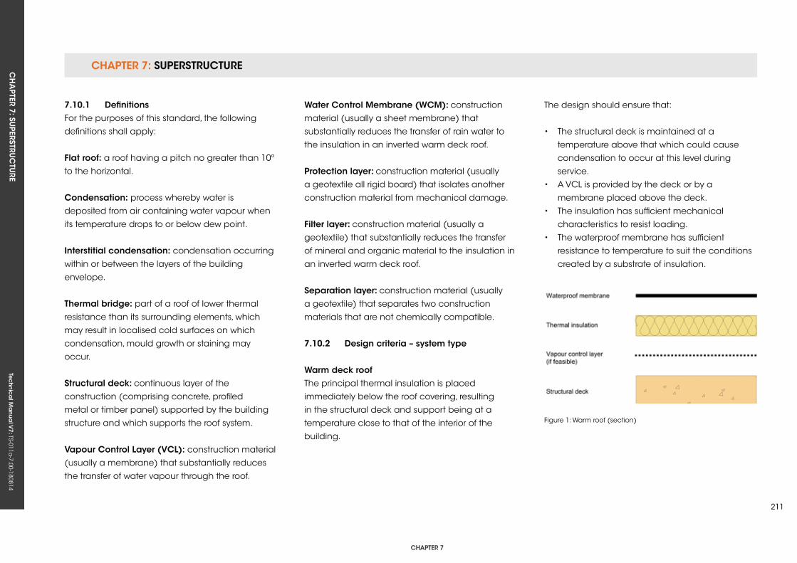
CHAPTER 7: SuPERSTRuCTuRECH
APTER 7: Su
PERSTRuC
TuRE
Tec
hn
ica
l Ma
nua
l V7: TS-011a
-7.00-180814
CHAPTER 7
211
7.10.1 DefinitionsFor the purposes of this standard, the following
definitions shall apply:
flat roof: a roof having a pitch no greater than 10º
to the horizontal.
Condensation: process whereby water is
deposited from air containing water vapour when
its temperature drops to or below dew point.
interstitial condensation: condensation occurring
within or between the layers of the building
envelope.
Thermal bridge: part of a roof of lower thermal
resistance than its surrounding elements, which
may result in localised cold surfaces on which
condensation, mould growth or staining may
occur.
structural deck: continuous layer of the
construction (comprising concrete, profiled
metal or timber panel) supported by the building
structure and which supports the roof system.
vapour Control Layer (vCL): construction material
(usually a membrane) that substantially reduces
the transfer of water vapour through the roof.
Water Control Membrane (WCM): construction
material (usually a sheet membrane) that
substantially reduces the transfer of rain water to
the insulation in an inverted warm deck roof.
Protection layer: construction material (usually
a geotextile all rigid board) that isolates another
construction material from mechanical damage.
filter layer: construction material (usually a
geotextile) that substantially reduces the transfer
of mineral and organic material to the insulation in
an inverted warm deck roof.
separation layer: construction material (usually
a geotextile) that separates two construction
materials that are not chemically compatible.
7.10.2 Design criteria – system type
Warm deck roofThe principal thermal insulation is placed
immediately below the roof covering, resulting
in the structural deck and support being at a
temperature close to that of the interior of the
building.
The design should ensure that:
• The structural deck is maintained at a
temperature above that which could cause
condensation to occur at this level during
service.
• A VCL is provided by the deck or by a
membrane placed above the deck.
• The insulation has sufficient mechanical
characteristics to resist loading.
• The waterproof membrane has sufficient
resistance to temperature to suit the conditions
created by a substrate of insulation.
Figure 1: Warm roof (section)
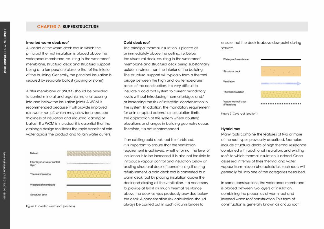
CHAPTER 7: SuPERSTRuCTuRE CH
APTER 7: Su
PERSTRuC
TuRE
Tec
hn
ica
l Ma
nua
l V7: TS-011a
-7.00-180814
inverted warm deck roofA variant of the warm deck roof in which the
principal thermal insulation is placed above the
waterproof membrane, resulting in the waterproof
membrane, structural deck and structural support
being at a temperature close to that of the interior
of the building. Generally, the principal insulation is
secured by separate ballast (paving or stone).
A filter membrane or (WCM) should be provided
to control mineral and organic material passing
into and below the insulation joints. A WCM is
recommended because it will provide improved
rain water run off, which may allow for a reduced
thickness of insulation and reduced loading of
ballast. If a WCM is included, it is essential that the
drainage design facilitates the rapid transfer of rain
water across the product and to rain water outlets.
Figure 2: Inverted warm roof (section)
Cold deck roofThe principal thermal insulation is placed at
or immediately above the ceiling, i.e. below
the structural deck, resulting in the waterproof
membrane and structural deck being substantially
colder in winter than the interior of the building.
The structural support will typically form a thermal
bridge between the high and low temperature
zones of the construction. It is very difficult to
insulate a cold roof system to current mandatory
levels without introducing thermal bridges and/
or increasing the risk of interstitial condensation in
the system. In addition, the mandatory requirement
for uninterrupted external air circulation limits
the application of the system where abutting
elevations or changes in building geometry occur.
Therefore, it is not recommended.
If an existing cold deck roof is refurbished,
it is important to ensure that the ventilation
requirement is achieved, whether or not the level of
insulation is to be increased. It is also not feasible to
introduce vapour control and insulation below an
existing structural deck of concrete, e.g. if during
refurbishment, a cold deck roof is converted to a
warm deck roof by placing insulation above the
deck and closing off the ventilation. It is necessary
to provide at least as much thermal resistance
above the deck as was previously provided below
the deck. A condensation risk calculation should
always be carried out in such circumstances to
ensure that the deck is above dew point during
service.
Hybrid roofMany roofs combine the features of two or more
of the roof types previously described. Examples
include structural decks of high thermal resistance
combined with additional insulation, and existing
roofs to which thermal insulation is added. Once
assessed in terms of their thermal and water
vapour transmission characteristics, such roofs will
generally fall into one of the categories described.
In some constructions, the waterproof membrane
is placed between two layers of insulation,
combining the properties of warm roof and
inverted warm roof construction. This form of
construction is generally known as a ‘duo roof’.
Figure 3: Cold roof (section)
CHAPTER 7: SuPERSTRuCTuRECH
APTER 7: Su
PERSTRuC
TuRE
Tec
hn
ica
l Ma
nua
l V7: TS-011a
-7.00-180814
CHAPTER 7
213
7.10.3 Loading
7.10.3.1 statutory requirementDesign for loading complies with the current
Building Regulations.
7.10.3.2 resistance to wind loadIn all situations, including ballasted, green and
inverted roofs, a calculation of wind load at each
zone of the roof to BS EN 1991-1-4 should be
undertaken by a suitably competent person.
7.10.3.3 resistance to imposed loadsAt the earliest possible stage, the employer should
define the range of potential functions of the
roof with regards loading with equipment, e.g.
air handling, renewable energy capture and the
intensity and frequency of foot traffic. This should
inform the selection of the deck, insulation, safety
guarding and protection.
7.10.4 falls and drainage
7.10.4.1 statutory requirementDesign for drainage should comply with the current
Building Regulations.
7.10.4.2 British and industry standardsBS 6229 states that a minimum finished fall at any
point of 1:80 (1.25%) should be achieved. Since
adjoining roof planes at 1:80 will meet at a mitre
of less than 1:80, the intended finished fall at such
intersections should be considered at an early stage.
Design falls should take account of any potential
deflection and construction tolerances. In the
absence of detailed calculations, this may
necessitate design falls of twice the minimum
finished falls (1:40 or 2.5%). Cut-to-falls systems are
often produced to a 1:60 (1.7%) fall or 1:40 (2.5%)
fall to ensure that deflection of the deck and/
or construction tolerances are overcome. This is
particularly important in designing inverted roofs,
where calculation of dead loading should be
based upon the ballast type and depth to be used.
The manufacturers of certain waterproofing
products have certification for their use in
‘completely flat’ or ‘zero falls’ applications. For the
purposes of this standard, the design conditions of
BS 6229 shall be assumed to prevail.
Consideration should also be given to:
• The available upstand height at the high end
of the falls. This may be a limiting factor on the
length/size of the roof area to be drained.
• Avoidance of ponding behind wide
obstructions to the drained slope, such as plant
plinths or roof lights.
• Avoidance of gutters by designing with
intersecting roof planes.
• Falls between rain water outlets along a
perimeter.
Since the primary function of the roof is to exclude
water, it is important to consider how best to direct
this into the drainage system.
Ponding on membrane roofs should be avoided
because:
• It encourages the deposition of dirt and leaves,
which can be unsightly, may obstruct outlets
and/or become a slip hazard.
• In the event of damage, the interior will suffer
increased water ingress.
• The load may cause progressive deflection of
the deck.
• Ice or algae may create a slip or wind hazard,
particularly on walkways.
Independent research has shown that roofs with
extensive ponding require increased maintenance
input.
Waterproof coverings of all types are tested for
water absorption and water tightness as part of
third-party certification. However, the construction
process, including the installation of components
and the forming of seams, is clearly facilitated in
dry, well-drained conditions.
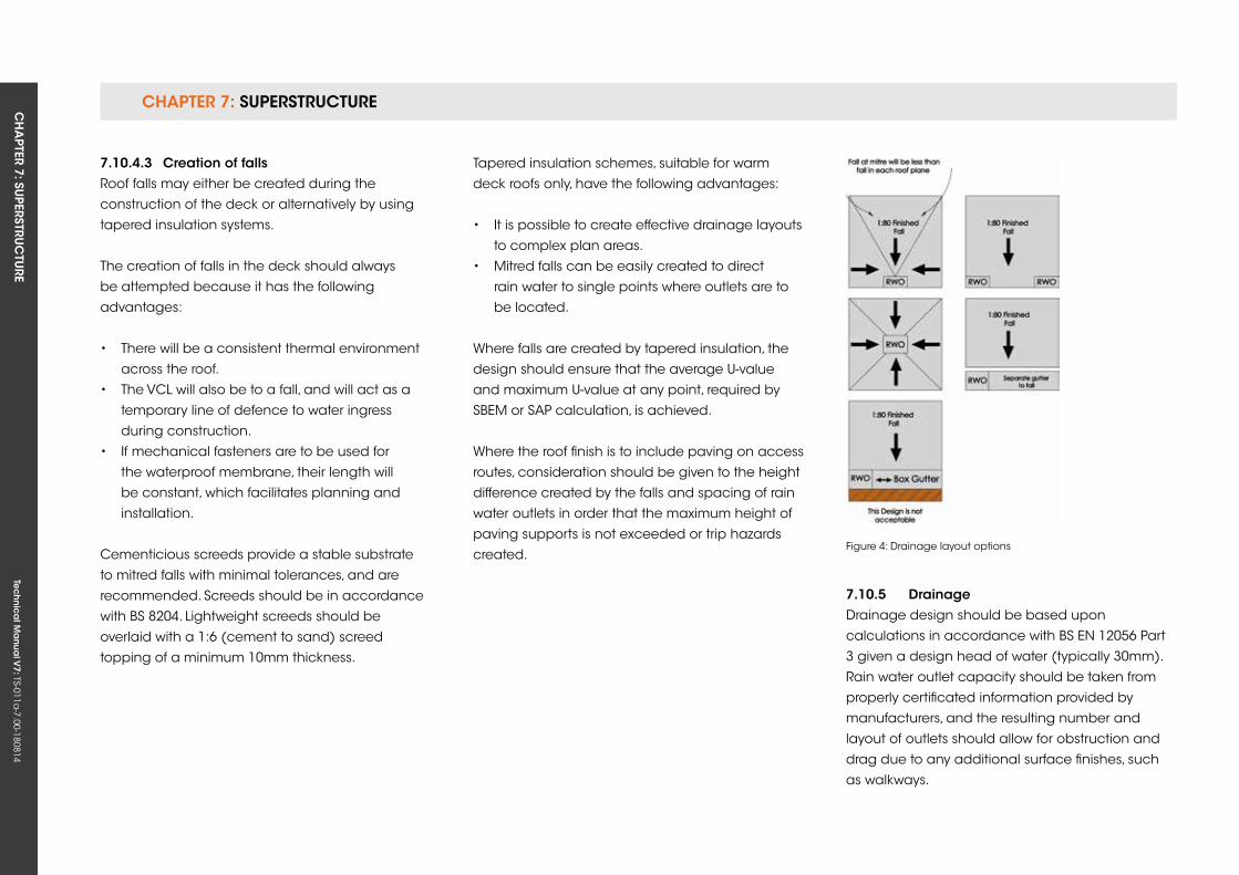
CHAPTER 7: SuPERSTRuCTuRE CH
APTER 7: Su
PERSTRuC
TuRE
Tec
hn
ica
l Ma
nua
l V7: TS-011a
-7.00-180814
7.10.4.3 Creation of fallsRoof falls may either be created during the
construction of the deck or alternatively by using
tapered insulation systems.
The creation of falls in the deck should always
be attempted because it has the following
advantages:
• There will be a consistent thermal environment
across the roof.
• The VCL will also be to a fall, and will act as a
temporary line of defence to water ingress
during construction.
• If mechanical fasteners are to be used for
the waterproof membrane, their length will
be constant, which facilitates planning and
installation.
Cementicious screeds provide a stable substrate
to mitred falls with minimal tolerances, and are
recommended. Screeds should be in accordance
with BS 8204. Lightweight screeds should be
overlaid with a 1:6 (cement to sand) screed
topping of a minimum 10mm thickness.
Tapered insulation schemes, suitable for warm
deck roofs only, have the following advantages:
• It is possible to create effective drainage layouts
to complex plan areas.
• Mitred falls can be easily created to direct
rain water to single points where outlets are to
be located.
Where falls are created by tapered insulation, the
design should ensure that the average u-value
and maximum u-value at any point, required by
SBEM or SAP calculation, is achieved.
Where the roof finish is to include paving on access
routes, consideration should be given to the height
difference created by the falls and spacing of rain
water outlets in order that the maximum height of
paving supports is not exceeded or trip hazards
created.
7.10.5 DrainageDrainage design should be based upon
calculations in accordance with BS EN 12056 Part
3 given a design head of water (typically 30mm).
Rain water outlet capacity should be taken from
properly certificated information provided by
manufacturers, and the resulting number and
layout of outlets should allow for obstruction and
drag due to any additional surface finishes, such
as walkways.
Figure 4: Drainage layout options
CHAPTER 7: SuPERSTRuCTuRECH
APTER 7: Su
PERSTRuC
TuRE
Tec
hn
ica
l Ma
nua
l V7: TS-011a
-7.00-180814
CHAPTER 7
215
It is not generally necessary to provide separate
box gutters where two planes of roofing intersect,
or where a single plane falls to an abutment. In the
latter case, there will be no fall between outlets, so
consideration should be given to creating these
in the structure or insulation. Box gutters are slow,
difficult to construct and introduce unnecessary
complexity. The need to maintain a fall in gutters
and comply with the energy requirements of the
Building Regulations may be difficult to achieve.
All waterproof membranes are compatible with
siphonic roof drainage systems, which for larger
roofs offer many advantages:
• Very high capacity, enabling fewer outlets and
therefore less detailing work on-site.
• Smaller bore horizontal collector pipe work,
enabling reduced roof void depth.
• Self-cleaning in many situations.
For further information, see
www.siphonic-roof-drainage.co.uk
7.10.6 Thermal performance
7.10.6.1 statutory requirementDesign for thermal performance must comply with
current Building Regulations, as appropriate.
7.10.6.2 Thermal transmittanceDesign for thermal transmittance should take
account of the effect of thermal bridging within the
roof field and at interfaces between the roof system
and adjoining elements, such as parapet walls or
abutments.
In particular, allowance should be made for the
effect of:
• Thermal bridging by metal fasteners used to
secure insulation and/or membrane. Thermal
break telescopic tube fasteners are
recommended to avoid this.
• Thermal bridging due to drainage of rain
water or snow-melt through insulation in
inverted roofs. The use of WCMs beneath ballast
to reduce thermal bridging is recommended.
• The locations of above-average thermal
transmittance at sumps, gutters or areas of
minimum thickness of tapered insulation.
Manufacturers of thermal insulation and WCMs
provide calculations of the effects of thermal
bridging by fasteners and drainage respectively.
Further advice is available in Building Research
Establishment BR 262 Thermal insulation: avoiding
risks, 2002 edition.
7.10.6.3 Air permeabilityRelevant contract drawings should define the
position of the component – the air barrier – that
determines resistance to air permeability. This may
be achieved by an additional, purpose-designed
membrane or by an additional function of another
component, such as the deck or waterproof
membrane.
7.10.6.4 Control of condensationAny provision required to control interstitial
condensation within the roof should be
determined to the calculation method defined by
BS 5250, but with ambient conditions set in BS 6229.
Calculated maximum accumulation of moisture
within thermal insulation should not exceed the
limits defined in BS 6229.
7.10.7 external fire performance
7.10.7.1 statutory requirementDesign for external fire performance must comply
with current Building Regulations.
7.10.7.2 Certification of systemThe manufacturer of the waterproof membrane
must demonstrate by reference to independent
test certification that the system of waterproofing
and insulation (type and thickness) for a particular
project meets or exceeds the minimum level of fire
performance defined by the Building Regulations.
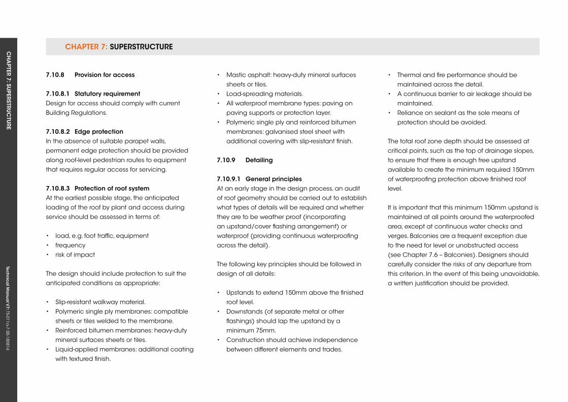
CHAPTER 7: SuPERSTRuCTuRE CH
APTER 7: Su
PERSTRuC
TuRE
Tec
hn
ica
l Ma
nua
l V7: TS-011a
-7.00-180814
7.10.8 Provision for access
7.10.8.1 statutory requirementDesign for access should comply with current
Building Regulations.
7.10.8.2 edge protectionIn the absence of suitable parapet walls,
permanent edge protection should be provided
along roof-level pedestrian routes to equipment
that requires regular access for servicing.
7.10.8.3 Protection of roof systemAt the earliest possible stage, the anticipated
loading of the roof by plant and access during
service should be assessed in terms of:
• load, e.g. foot traffic, equipment
• frequency
• risk of impact
The design should include protection to suit the
anticipated conditions as appropriate:
• Slip-resistant walkway material.
• Polymeric single ply membranes: compatible
sheets or tiles welded to the membrane.
• Reinforced bitumen membranes: heavy-duty
mineral surfaces sheets or tiles.
• Liquid-applied membranes: additional coating
with textured finish.
• Mastic asphalt: heavy-duty mineral surfaces
sheets or tiles.
• Load-spreading materials.
• All waterproof membrane types: paving on
paving supports or protection layer.
• Polymeric single ply and reinforced bitumen
membranes: galvanised steel sheet with
additional covering with slip-resistant finish.
7.10.9 Detailing
7.10.9.1 general principlesAt an early stage in the design process, an audit
of roof geometry should be carried out to establish
what types of details will be required and whether
they are to be weather proof (incorporating
an upstand/cover flashing arrangement) or
waterproof (providing continuous waterproofing
across the detail).
The following key principles should be followed in
design of all details:
• upstands to extend 150mm above the finished
roof level.
• Downstands (of separate metal or other
flashings) should lap the upstand by a
minimum 75mm.
• Construction should achieve independence
between different elements and trades.
• Thermal and fire performance should be
maintained across the detail.
• A continuous barrier to air leakage should be
maintained.
• Reliance on sealant as the sole means of
protection should be avoided.
The total roof zone depth should be assessed at
critical points, such as the top of drainage slopes,
to ensure that there is enough free upstand
available to create the minimum required 150mm
of waterproofing protection above finished roof
level.
It is important that this minimum 150mm upstand is
maintained at all points around the waterproofed
area, except at continuous water checks and
verges. Balconies are a frequent exception due
to the need for level or unobstructed access
(see Chapter 7.6 – Balconies). Designers should
carefully consider the risks of any departure from
this criterion. In the event of this being unavoidable,
a written justification should be provided.
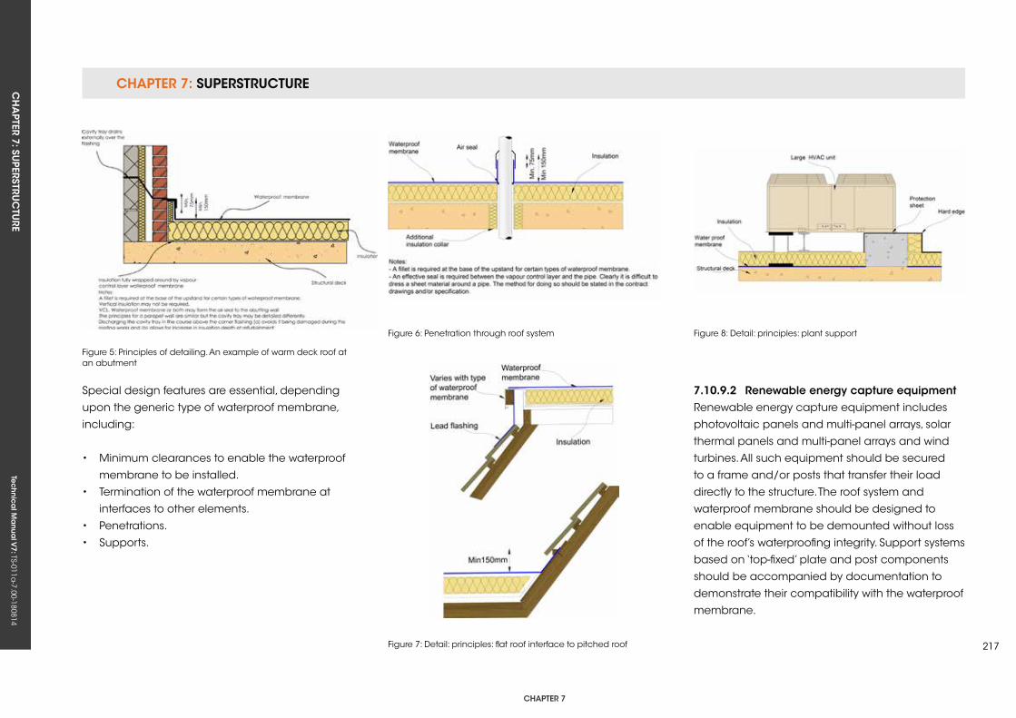
CHAPTER 7: SuPERSTRuCTuRECH
APTER 7: Su
PERSTRuC
TuRE
Tec
hn
ica
l Ma
nua
l V7: TS-011a
-7.00-180814
CHAPTER 7
217
Figure 5: Principles of detailing. An example of warm deck roof at an abutment
Figure 6: Penetration through roof system Figure 8: Detail: principles: plant support
Figure 7: Detail: principles: flat roof interface to pitched roof
Special design features are essential, depending
upon the generic type of waterproof membrane,
including:
• Minimum clearances to enable the waterproof
membrane to be installed.
• Termination of the waterproof membrane at
interfaces to other elements.
• Penetrations.
• Supports.
7.10.9.2 renewable energy capture equipmentRenewable energy capture equipment includes
photovoltaic panels and multi-panel arrays, solar
thermal panels and multi-panel arrays and wind
turbines. All such equipment should be secured
to a frame and/or posts that transfer their load
directly to the structure. The roof system and
waterproof membrane should be designed to
enable equipment to be demounted without loss
of the roof’s waterproofing integrity. Support systems
based on ‘top-fixed’ plate and post components
should be accompanied by documentation to
demonstrate their compatibility with the waterproof
membrane.
CHAPTER 7: SuPERSTRuCTuRE CH
APTER 7: Su
PERSTRuC
TuRE
Tec
hn
ica
l Ma
nua
l V7: TS-011a
-7.00-180814
7.10.9.3 Handrails and balustradesSee Chapter 7.6 – Balconies.
7.10.9.4 Mechanical and electrical servicesDetailed design should take account of the
installation of such equipment by other (usually
following) trades, as follows:
• Services entry/exit points should be suitably
weathered to enable connection without loss of
integrity of the waterproof membrane.
• The upstand of the waterproof membrane at
risers should be arranged to enable a separate
downstand or weathering flashing to be formed
in ductwork.
• Cladding to insulation placed around ductwork
should not be sealed to the waterproof
membrane.
• Sufficient clearance should be provided to
horizontal ductwork to ensure it does not rest
upon the waterproof membrane or roof finish.
7.10.10 Materials
7.10.10.1 requirement
generalMaterials for use in flat roofing systems are suitable
only if the manufacturer has declared compliance
with the relevant harmonised European Product
Specification and has affixed the CE Mark to the
product. Where no relevant harmonised European
Product Specification exists, the product should
either comply with a relevant British Standard or be
independently certificated for fitness for purpose by
the British Board of Agrément or other notified body.
7.10.10.2 structural deck
generalAt the earliest practical stage, the likely deflection
in the deck, and the tolerance in the level of its
finish, should be confirmed, because this informs
the design for drainage. If the deck is intended to
receive mechanical fasteners for the attachment
of roof system components such as insulation,
or equipment such as fall-arrest line posts, its
resistance to pull-out should also be confirmed.
Concrete Precast concrete construction should be designed
in accordance with BS 8110. Information on span
capability and the installation requirements
of precast panels can be obtained from
manufacturers. Information on the location of
required movement joints should be obtained early
in the design process as they have implications
for drainage layout and detailing. Precast panels
installed to a fall can provide a simple layout but
without cross falls.
In-situ concrete construction should be designed
in accordance with BS 8110. It is more difficult to
lay to a fall, and it is more common to create falls
in the insulation (warm roofs only) or by using an
additional screed. Information on compressive
strength, resistance to point load and drying
periods of wet screeds can be obtained from
suppliers and relevant trade associations.
Where structural movement joints are required in
large concrete decks, a clearly defined movement
joint detail should be constructed to a design and
with the materials that afford durability equivalent
to that of the roof system.
Profiled metal (steel or aluminium)Profiled metal decks should have a crown width at
least 50% of the profile width. To provide a sound
base for the insulation and waterproofing system,
and to avoid reduced drainage performance,
the mid-span deflection of the metal deck should
not exceed 1/200 of the span under uniformly
distributed design loads. When considering the
deck profile and the necessity for side lap stitching
and metal deck closures, reference should be
made to the manufacturers of the deck, insulation
and membrane.
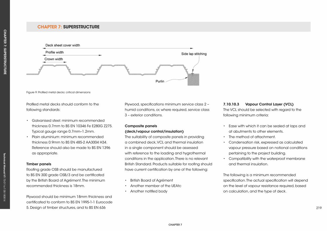
CHAPTER 7: SuPERSTRuCTuRECH
APTER 7: Su
PERSTRuC
TuRE
Tec
hn
ica
l Ma
nua
l V7: TS-011a
-7.00-180814
CHAPTER 7
219
Profiled metal decks should conform to the
following standards:
• Galvanised steel: minimum recommended
thickness 0.7mm to BS EN 10346 Fe E280G Z275.
Typical gauge range 0.7mm–1.2mm.
• Plain aluminium: minimum recommended
thickness 0.9mm to BS EN 485-2 AA3004 H34.
Reference should also be made to BS EN 1396
as appropriate.
Timber panelsRoofing grade OSB should be manufactured
to BS EN 300 grade OSB/3 and be certificated
by the British Board of Agrément. The minimum
recommended thickness is 18mm.
Plywood should be minimum 18mm thickness and
certificated to conform to BS EN 1995-1-1 Eurocode
5. Design of timber structures, and to BS EN 636
Figure 9: Profiled metal decks: critical dimensions
Plywood, specifications minimum service class 2 –
humid conditions, or, where required, service class
3 – exterior conditions.
Composite panels (deck/vapour control/insulation)The suitability of composite panels in providing
a combined deck, VCL and thermal insulation
in a single component should be assessed
with reference to the loading and hygrothermal
conditions in the application. There is no relevant
British Standard. Products suitable for roofing should
have current certification by one of the following:
• British Board of Agrément
• Another member of the uEAtc
• Another notified body
7.10.10.3 vapour Control Layer (vCL)The VCL should be selected with regard to the
following minimum criteria:
• Ease with which it can be sealed at laps and
at abutments to other elements.
• The method of attachment.
• Condensation risk, expressed as calculated
vapour pressure based on notional conditions
pertaining to the project building.
• Compatibility with the waterproof membrane
and thermal insulation.
The following is a minimum recommended
specification. The actual specification will depend
on the level of vapour resistance required, based
on calculation, and the type of deck.
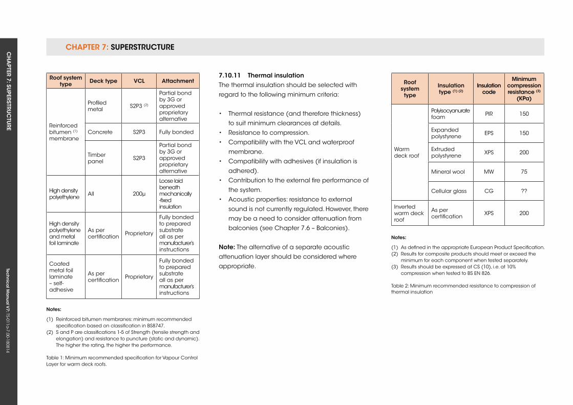
CHAPTER 7: SuPERSTRuCTuRE CH
APTER 7: Su
PERSTRuC
TuRE
Tec
hn
ica
l Ma
nua
l V7: TS-011a
-7.00-180814
7.10.11 Thermal insulationThe thermal insulation should be selected with
regard to the following minimum criteria:
• Thermal resistance (and therefore thickness)
to suit minimum clearances at details.
• Resistance to compression.
• Compatibility with the VCL and waterproof
membrane.
• Compatibility with adhesives (if insulation is
adhered).
• Contribution to the external fire performance of
the system.
• Acoustic properties: resistance to external
sound is not currently regulated. However, there
may be a need to consider attenuation from
balconies (see Chapter 7.6 – Balconies).
note: The alternative of a separate acoustic
attenuation layer should be considered where
appropriate.
roof system type Deck type vCL Attachment
Reinforced bitumen (1) membrane
Profiled metal S2P3 (2)
Partial bond by 3G or approved proprietary alternative
Concrete S2P3 Fully bonded
Timber panel S2P3
Partial bond by 3G or approved proprietary alternative
High density polyethylene All 200μ
Loose laid beneath mechanically-fixed insulation
High density polyethylene and metal foil laminate
As per certification Proprietary
Fully bonded to prepared substrate all as per manufacturer’s instructions
Coated metal foil laminate – self-adhesive
As per certification Proprietary
Fully bonded to prepared substrate all as per manufacturer’s instructions
notes:
(1) Reinforced bitumen membranes: minimum recommended specification based on classification in BS8747.(2) S and P are classifications 1-5 of Strength (tensile strength and elongation) and resistance to puncture (static and dynamic). The higher the rating, the higher the performance.
Table 1: Minimum recommended specification for Vapour Control Layer for warm deck roofs.
roof system
type
insulation type (1) (2)
insulation code
Minimum compression resistance (3)
(kPa)
Warm deck roof
Polyisocyanurate foam PIR 150
Expanded polystyrene EPS 150
Extruded polystyrene xPS 200
Mineral wool MW 75
Cellular glass CG ??
Inverted warm deck roof
As per certification xPS 200
notes:
(1) As defined in the appropriate European Product Specification.(2) Results for composite products should meet or exceed the minimum for each component when tested separately. (3) Results should be expressed at CS (10), i.e. at 10% compression when tested to BS EN 826.
Table 2: Minimum recommended resistance to compression of thermal insulation
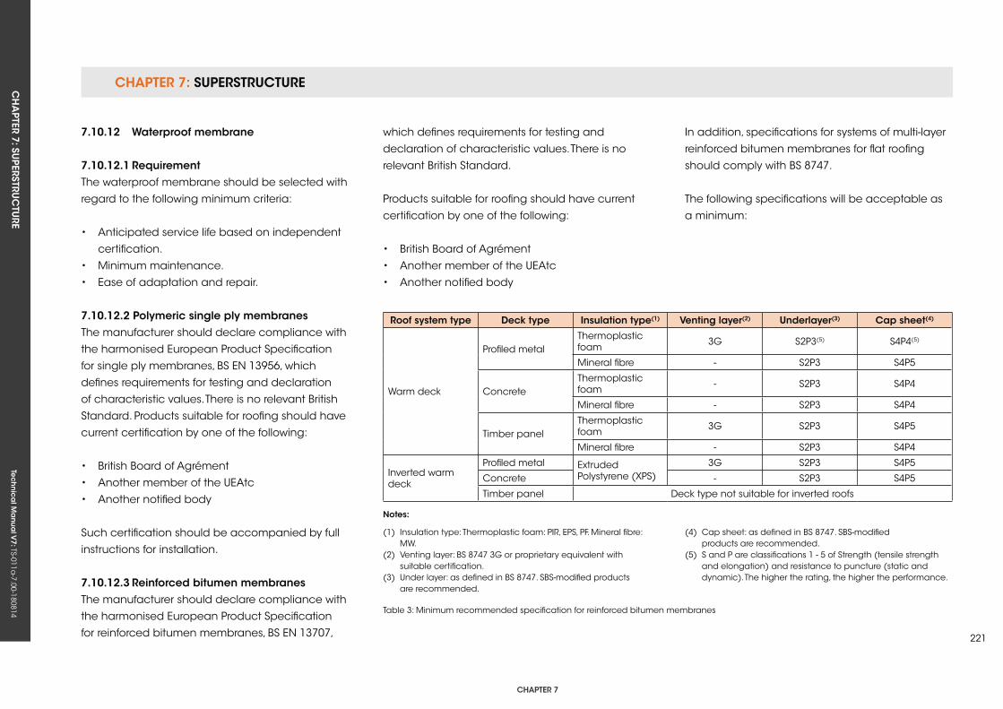
CHAPTER 7: SuPERSTRuCTuRECH
APTER 7: Su
PERSTRuC
TuRE
Tec
hn
ica
l Ma
nua
l V7: TS-011a
-7.00-180814
CHAPTER 7
221
which defines requirements for testing and
declaration of characteristic values. There is no
relevant British Standard.
Products suitable for roofing should have current
certification by one of the following:
• British Board of Agrément
• Another member of the uEAtc
• Another notified body
notes:
roof system type Deck type insulation type(1) venting layer(2) underlayer(3) Cap sheet(4)
Warm deck
Profiled metalThermoplastic foam 3G S2P3(5) S4P4(5)
Mineral fibre - S2P3 S4P5
ConcreteThermoplastic foam - S2P3 S4P4
Mineral fibre - S2P3 S4P4
Timber panelThermoplastic foam 3G S2P3 S4P5
Mineral fibre - S2P3 S4P4
Inverted warm deck
Profiled metal Extruded Polystyrene (xPS)
3G S2P3 S4P5
Concrete - S2P3 S4P5
Timber panel Deck type not suitable for inverted roofs
In addition, specifications for systems of multi-layer
reinforced bitumen membranes for flat roofing
should comply with BS 8747.
The following specifications will be acceptable as
a minimum:
Table 3: Minimum recommended specification for reinforced bitumen membranes
(1) Insulation type: Thermoplastic foam: PIR, EPS, PF. Mineral fibre: MW.(2) Venting layer: BS 8747 3G or proprietary equivalent with suitable certification.(3) under layer: as defined in BS 8747. SBS-modified products are recommended.
(4) Cap sheet: as defined in BS 8747. SBS-modified products are recommended.(5) S and P are classifications 1 - 5 of Strength (tensile strength and elongation) and resistance to puncture (static and dynamic). The higher the rating, the higher the performance.
7.10.12 Waterproof membrane
7.10.12.1 requirementThe waterproof membrane should be selected with
regard to the following minimum criteria:
• Anticipated service life based on independent
certification.
• Minimum maintenance.
• Ease of adaptation and repair.
7.10.12.2 Polymeric single ply membranesThe manufacturer should declare compliance with
the harmonised European Product Specification
for single ply membranes, BS EN 13956, which
defines requirements for testing and declaration
of characteristic values. There is no relevant British
Standard. Products suitable for roofing should have
current certification by one of the following:
• British Board of Agrément
• Another member of the uEAtc
• Another notified body
Such certification should be accompanied by full
instructions for installation.
7.10.12.3 reinforced bitumen membranesThe manufacturer should declare compliance with
the harmonised European Product Specification
for reinforced bitumen membranes, BS EN 13707,
CHAPTER 7: SuPERSTRuCTuRE CH
APTER 7: Su
PERSTRuC
TuRE
Tec
hn
ica
l Ma
nua
l V7: TS-011a
-7.00-180814
Bitumen membranes should be protected from
solar radiation. This should be by integral protection
provided in the product in the form of:
• Mineral granules
• Metal foil
The use of solar reflective paint is not permitted.
The use of stone chippings is not recommended
unless required to achieve enhanced external fire
performance. If used, chippings should be washed,
crushed rock, normally 10mm–14mm nominal size
aggregate, bedded in a proprietary gritting solution.
7.10.12.4 Liquid-applied membranesThere is no harmonised European Product
Specification for liquid applied membranes
for roofing. The European Technical Approval
Guideline ETAG 005 Part 1 – General gives overall
guidance on assessment of fitness for use,
including methods of verification and attestation
of conformity. The remaining seven parts, known
as the Complementary Parts or the ETA Parts, deal
with specific requirements for particular families
of products, and are the generic types covered
primarily by this Guidance Note, shown as follows:
• Part 2: Polymer modified bitumen emulsions
and solutions
• Part 3: Glass reinforced resilient unsaturated
polyester resins
• Part 4: Flexible unsaturated polyesters
• Part 5: Hot applied polymer modified
bitumens
• Part 6: Polyurethanes
• Part 7: Bitumen emulsions and solutions
• Part 8: Water dispersible polymers
The manufacturer of a product for use in flat
roofing should declare compliance with the
relevant parts of ETAG 005. In the absence of this
declaration, the product should have a current
certificate of fitness for purpose issued by one of
the following:
• British Board of Agrément
• Another member of the uEAtc
• Another notified body
Such certification should be accompanied by full
instructions for installation.
7.10.12.5 Mastic asphaltThere is no harmonised European Product
Specification for mastic asphalt for roofing. Products
used for flat roofing should comply with BS 6925:
1988 Specification for mastic asphalt for buildings
and civil engineering (limestone aggregate).
Proprietary grades of polymer modified mastic
asphalt are produced for roofing and paving
applications. There is no British Standard or
European Standard for these products.
Products suitable for roofing should have current
certification by one of the following:
• British Board of Agrément
• Another member of the uEAtc
• Another notified body
The separating membrane should be one of the
following, and should be laid directly under the
mastic asphalt:
• Sheathing felt, comprising a base of flax or jute,
or other suitable fibres, impregnated with bitumen.
• Glass fibre tissue.
Bitumen-coated plain expanded metal lathing
should be in accordance with BS EN 13658-2.
Stone chippings (bedded) for use as a protective
topping should be washed, crushed rock, normally
10mm–14mm nominal size aggregate, bedded in a
proprietary gritting solution over the mastic asphalt
membrane.
CHAPTER 7: SuPERSTRuCTuRECH
APTER 7: Su
PERSTRuC
TuRE
Tec
hn
ica
l Ma
nua
l V7: TS-011a
-7.00-180814
CHAPTER 7
223
7.10.12.6 site-applied hot-melt coveringsThere is no harmonised European Product
Specification for site-applied hot-melt waterproofing
systems.
Products suitable for roofing should have current
certification by one of the following:
• British Board of Agrément
• Another member of the uEAtc
• Another notified body
As these systems comprise a multi-layer application
(usually a base coat, reinforcement and top coat),
a detailed specification for the system should be
available prior to commencement of the works to
enable its suitability for the project to be confirmed.
7.10.13 Ancillary components
7.10.13.1 non-access areas: stone ballastStone ballast for inverted warm deck roofs and
ballasted warm deck roofs should be clean,
rounded aggregate graded 20mm–40mm and
as free from fines as practicable. Ballast should be
applied over a protection layer or WCM in warm
ballasted and inverted warm roofs respectively.
7.10.13.2 Access areas: concrete paving slabs Concrete paving slabs for use as walkways or
as paving on terrace decks should conform to
BS EN 1340, and be laid in accordance with the
manufacturer’s instructions.
7.10.13.3 Access areas: porous concrete tiles (for use on reinforced bitumen sheets and mastic asphalt only)Porous concrete tiles should be fully bonded in hot
bitumen in accordance with the manufacturer’s
instructions.
7.10.13.4 Access areas: flexible walkway tilesEvidence of the compatibility of the tile with the
waterproof membrane is required. Tiles for walkways
or terrace deck paving should be bedded in
a bonding compound compatible with the
waterproof membrane and fixed in accordance
with the tile manufacturer’s recommendations.
7.10.13.5 rain water outletsThe following should be confirmed by reference
to the manufacturer’s information or independent
certification, as appropriate:
• Capacity in litres per second at a range of
typical water heads.
• Compatibility with the waterproof membrane.
• Integral insulation to avoid condensation.
• Method of attachment.
7.10.13.6 fall-arrest and edge protection equipmentThe following should be confirmed by reference
to the manufacturer’s information or independent
certification, as appropriate:
• Compliance with BS EN 795.
• Method of attachment.
• Compatibility with the waterproof membrane.
• Means of forming a water tight seal to the
waterproof membrane.
7.10.13.7 Lightning protectionThe following should be confirmed by reference
to the manufacturer’s information or independent
certification, as appropriate:
• Design in compliance with BS EN 62305.
• Method of attachment to the waterproof
membrane, including arrangements for self-
ballasting of conductors and finials (centres,
compressive loads).
• Recommended detailing at penetration of roof
system.
7.10.13.8 support for renewable energy capture equipmentRenewable energy equipment includes
photovoltaic panels and multi-panel arrays,
solar thermal panels and multi-panel arrays and
wind turbines. All such equipment should be
CHAPTER 7: SuPERSTRuCTuRE CH
APTER 7: Su
PERSTRuC
TuRE
Tec
hn
ica
l Ma
nua
l V7: TS-011a
-7.00-180814
secured to a frame and/or posts that transfer
their load directly to the structure. Support systems
based on ‘top-fixed’ plate and post components
are acceptable only if accompanied by
documentation to demonstrate their dead and
live loading capacity and compatibility with the
waterproof membrane.
7.10.14 Compatibility of componentsThe selection of components within the roofing
system should be discussed in detail with the
membrane manufacturer or appropriate trade
association to ensure chemical and mechanical
compatibility between components, since the
incorrect specification may lead to reduced
performance or premature failure of the roofing
system. The correct choice of insulation is also
important when it is to be adhered to the substrate.
In case of doubt, the insulation manufacturer or
relevant trade association should be consulted.
7.10.15 installation
7.10.15.1 Protection of the roofTemporary protection (during construction)
Responsibility for temporary protection and a
method statement for its use should be agreed
prior to commencement of works. Suitable
materials should be selected in consultation with
membrane manufacturers as appropriate, for
example:
• Linked recycled thermoplastic sheets.
• Rolled recycled thermoplastic or elastomeric
sheets.
Particular consideration should be given to
locations of concentrated access, such as step-out
areas onto the roof or where wheeled equipment
may be used.
Permanent protection (during service)Permanent protection should not be laid on routes
where access is most likely, and should not be laid
on routes where temporary ponding is likely, e.g.
near parapet walls in the absence of cross falls
between rain water outlets.
It is recommended that concrete paving is laid
on support pads, as this allows adjustment, thus
reducing the risk of a trip hazard:
• The height of support pads should not exceed
the maximum recommended by the
manufacturer.
• Paving should not be cut.
• Paving should be firmly butted up against
support pad separating pegs.
7.10.15.2 vapour Control Layer (vCL)The attachment of the VCL should be designed to
resist calculated wind load by a declared margin
of safety. All laps should be sealed and the VCL
should be sealed to the adjoining element, which
forms the continuation of the resistance to air
permeability. The VCL should be extended behind
all thermal insulation, including insulation placed
on vertical surfaces such as parapet walls. Where
the roof system is penetrated by a detail such as
a pipe or duct, a suitable method for providing
continuous vapour control should be provided,
and this method should be followed in practice.
Where a reinforced bitumen membrane VCL is
used, its installation should be in accordance with
BS 8217.
7.10.15.3 Thermal insulationThe attachment of the thermal insulation should
be designed to resist calculated wind load by a
declared margin of safety. This includes consideration
of dead loads required in all roof zones in ballasted
warm roofs and inverted warm roofs.
Except in tapered insulation schemes, thermal
insulation should always be laid in a broken bond
pattern. Where two or more layers are laid, the
joints in each layer should be offset. On substrates
of profiled metal, the short dimension should be
parallel to the deck crowns and supported across
half the crown width.
Insulation should be lightly butted so as to avoid
thermal bridging caused by gaps. If large gaps are
created by damaged or undersized boards, any
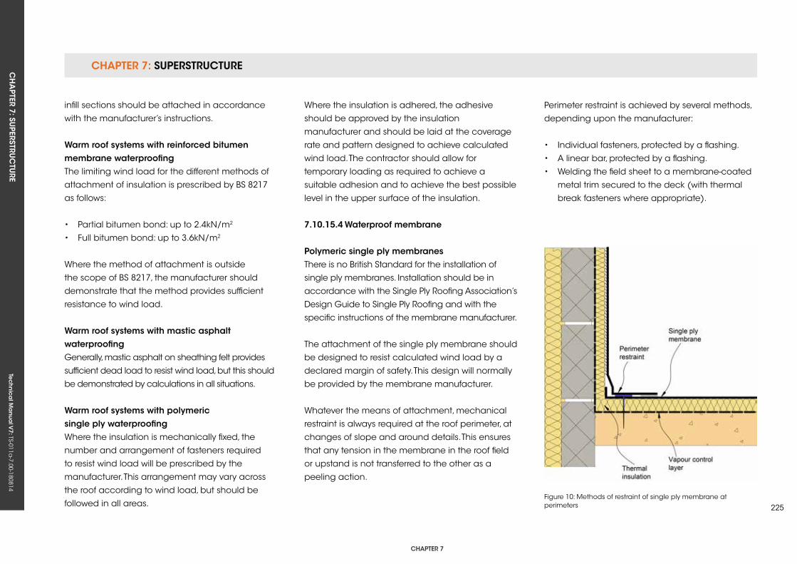
CHAPTER 7: SuPERSTRuCTuRECH
APTER 7: Su
PERSTRuC
TuRE
Tec
hn
ica
l Ma
nua
l V7: TS-011a
-7.00-180814
CHAPTER 7
225
infill sections should be attached in accordance
with the manufacturer’s instructions.
Warm roof systems with reinforced bitumen membrane waterproofingThe limiting wind load for the different methods of
attachment of insulation is prescribed by BS 8217
as follows:
• Partial bitumen bond: up to 2.4kN/m2
• Full bitumen bond: up to 3.6kN/m2
Where the method of attachment is outside
the scope of BS 8217, the manufacturer should
demonstrate that the method provides sufficient
resistance to wind load.
Warm roof systems with mastic asphalt waterproofingGenerally, mastic asphalt on sheathing felt provides
sufficient dead load to resist wind load, but this should
be demonstrated by calculations in all situations.
Warm roof systems with polymeric single ply waterproofingWhere the insulation is mechanically fixed, the
number and arrangement of fasteners required
to resist wind load will be prescribed by the
manufacturer. This arrangement may vary across
the roof according to wind load, but should be
followed in all areas.
Where the insulation is adhered, the adhesive
should be approved by the insulation
manufacturer and should be laid at the coverage
rate and pattern designed to achieve calculated
wind load. The contractor should allow for
temporary loading as required to achieve a
suitable adhesion and to achieve the best possible
level in the upper surface of the insulation.
7.10.15.4 Waterproof membrane
Polymeric single ply membranesThere is no British Standard for the installation of
single ply membranes. Installation should be in
accordance with the Single Ply Roofing Association’s
Design Guide to Single Ply Roofing and with the
specific instructions of the membrane manufacturer.
The attachment of the single ply membrane should
be designed to resist calculated wind load by a
declared margin of safety. This design will normally
be provided by the membrane manufacturer.
Whatever the means of attachment, mechanical
restraint is always required at the roof perimeter, at
changes of slope and around details. This ensures
that any tension in the membrane in the roof field
or upstand is not transferred to the other as a
peeling action.
Perimeter restraint is achieved by several methods,
depending upon the manufacturer:
• Individual fasteners, protected by a flashing.
• A linear bar, protected by a flashing.
• Welding the field sheet to a membrane-coated
metal trim secured to the deck (with thermal
break fasteners where appropriate).
Figure 10: Methods of restraint of single ply membrane at perimeters
CHAPTER 7: SuPERSTRuCTuRE CH
APTER 7: Su
PERSTRuC
TuRE
Tec
hn
ica
l Ma
nua
l V7: TS-011a
-7.00-180814
If the remainder of the roof system is to be bonded,
it is essential that the design resistance to wind
load is also achieved for the attachment of these
components.
Irrespective of the wind uplift considerations
or distribution requirements for securing the
membrane, the fixing of the insulation boards
should always be considered separately, unless
specifically sanctioned by the membrane
manufacturer. The number and distribution
of mechanical fasteners required to fix the
insulation boards may vary with the insulation
type, geographical location of the building,
topographical data and the height of the roof
concerned.
The upper termination of the single ply membrane
at linear details such as plinths, parapets,
abutments and door openings should be secured
by one of the following mechanical means:
• Clamping beneath a metal rail, e.g. a parapet
capping or roof light frame.
• Welding to a membrane-metal laminate trim
(itself mechanically fixed).
• Mechanical fixing using individual fasteners or
a mechanically fixed termination bar.
reinforced bitumen membranesInstallation should be in accordance with BS
8217. In case of doubt, or where the waterproof
membrane is beyond the scope of the Standard,
the advice of the Flat Roofing Alliance (National
Federation of Roofing Contractors) should prevail.
The safe use of gas torches, and the positioning,
monitoring and transferring hot bitumen to the
work face, should be adopted, all in accordance
with the Health & Safety Executive/Flat Roofing
Alliance Code of Practice for Safe Handling of
Bitumen.
The practice of applying reinforced bitumen
membranes by torching onto thermoplastic foam
insulation is not permitted, unless the boards
are manufactured with a covering of reinforced
bitumen membrane.
Liquid-applied membranesThere is no British Standard for the installation of
liquid-applied membranes. Installation should
be in accordance with the Liquid Roofing and
Waterproofing Association guidance, as follows:
• Guidance Note No. 2 – Substrates for Liquid-
applied Waterproofing.
• Guidance Note No. 4 – Roof, Balcony and
Walkway Refurbishment using Liquid-applied
Waterproofing Systems.
• Guidance Note No. 5 – Health and Safety
Provision for LAWS on Roofs, Balconies and
Walkways.
• Guidance Note No. 6 – Safe use of Liquid-
applied Waterproofing Systems.
Mastic asphaltThe number of coats should be appropriate to the
waterproofing requirements and traffic conditions
of the roof. When laid to falls of 1:80 or more, mastic
asphalt roofing is laid in two coats to a thickness
of 20mm, on a separating membrane of sheathing
felt, all in accordance with BS 8218.
On sloping and vertical surfaces over 10° pitch,
the mastic asphalt should be laid in three coats
to a thickness of 20mm without a separating
membrane.
On sloping and vertical surfaces of timber or
lightweight concrete, the mastic asphalt should
be laid in three coats to a thickness of 20mm
on expanded metal lathing over a separating
membrane of sheathing felt.
site-applied hot-melt coveringsThere is no British Standard for the application of
proprietary hot-melt waterproof membrane systems.
Reference should be made to independent
certification and the manufacturer’s detailed
instructions.
CHAPTER 7: SuPERSTRuCTuRECH
APTER 7: Su
PERSTRuC
TuRE
Tec
hn
ica
l Ma
nua
l V7: TS-011a
-7.00-180814
CHAPTER 7
227
7.10.16 Testing
7.10.16.1 final inspectionAt practical completion of the flat roof, all
areas should be clear of stored material, other
site operations and all protection. A thorough,
recorded, visual inspection of all areas, including
details, should be carried out with representation
from the General Contractor and Roofing
Contractor in attendance.
7.10.16.2 Procurement of testing servicesIf testing to demonstrate waterproofing integrity is
required, it should be undertaken by a third-party
that is independent of the roofing contract.
The testing service provider should provide
evidence of the following:
• Efficacy of the method proposed in the
circumstances of the project.
• Experience and training of operator.
• Membership of an appropriate trade
association that sets a Code of Conduct for the
service.
7.10.16.3 Methods of test
Low voltage earth leakageLow voltage earth leakage is a safe and effective
method for the testing of waterproofing integrity
in roofs where the waterproof membrane is an
electrical insulator and the deck provides an
electrical earth. It is not suitable for testing flat
roofs where the waterproof membrane has been
overlaid with insulation and ballast (inverted roofs)
or ballast only (ballasted warm roofs); therefore,
testing should be carried out prior to completion of
the roofing system.
High voltage electrical discharge The high voltage electrical discharge method is
best suited to the testing of continuous thin films,
such as liquid-applied coatings. Its use is not
recommended with polymeric single ply, reinforced
bitumen membranes and mastic asphalt.
vacuum Vacuum testing of seams of membranes
manufactured off-site is an effective means of
quality assessment, but is not recommended as a
method of demonstrating the integrity of flat roofs.
flood testingFlood testing is not recommended as a method of
demonstrating the integrity of flat roofs. It may be
used to test balconies (see Chapter 7.6 – Balconies).
7.10.17 Provision of information
operation and maintenance manual The following information is required:
• Specification, as-built:
- Waterproof membrane: generic type,
product(s) and (as appropriate) thickness.
- Thermal insulation: generic type, product(s)
and thickness.
- Acoustic insulation: generic type, product
and (as appropriate) thickness.
- Vapour Control Layer: generic type, product
(as appropriate) and thickness (as
appropriate).
- Rain water outlets: type, product and
capacity.
• Procedure for maintenance of waterproof
membrane, including (where appropriate)
recommended frequency and method of
application of solar reflective finish.
• Procedure for repair of waterproof membrane.

Tec
hn
ica
l Ma
nua
l V6: TS-011a
-6.00-010413Te
ch
nic
al M
anu
al V
7: TS-011a-7.00-180814
FUNCTIONAL REQUIREMENTS
7.11 roof Coverings – green roofing
Workmanshipi. All workmanship must be within the tolerances defined in Chapter 1
of this Manual.
ii. All work is to be carried out by a technically competent person in a
workmanlike manner.
iii. Certification is required for any work completed by an approved
installer.
Materialsi. All materials should be stored correctly in a manner that will not cause
damage or deterioration of the product.
ii. All materials, products and building systems shall be appropriate and
suitable for their intended purpose.
iii. The structure shall, unless specifically agreed otherwise with the
Warranty provider, have a life of not less than 60 years. Individual
components and assemblies, not integral to the structure, may have a
lesser durability, but not in any circumstances less than 15 years.
Designi. The design and specifications shall provide a clear indication of the
design intent and demonstrate a satisfactory level of performance.
ii. Roof coverings must prevent any external moisture passing into the
internal environment of the dwelling.
iii. Structural elements outside the parameters of regional Approved
Documents must be supported by structural calculations provided by
a suitably qualified expert.
iv. The materials, design and construction must meet the relevant
Building Regulations, British Standards, Eurocodes and other statutory
requirements.
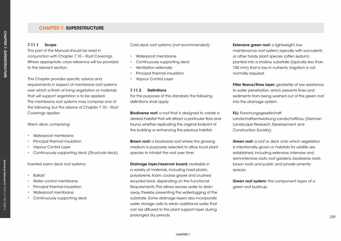
CHAPTER 7: SuPERSTRuCTuRECH
APTER 7: Su
PERSTRuC
TuRE
Tec
hn
ica
l Ma
nua
l V7: TS-011a
-7.00-180814
CHAPTER 7
229
7.11.1 scopeThis part of the Manual should be read in
conjunction with Chapter 7.10 – Roof Coverings.
Where appropriate, cross reference will be provided
to the relevant section.
This Chapter provides specific advice and
requirements in respect of membrane roof systems
over which a finish of living vegetation or materials
that will support vegetation is to be applied.
The membrane roof systems may comprise one of
the following, but the advice of Chapter 7.10 – Roof
Coverings applies:
Warm deck, comprising:
• Waterproof membrane
• Principal thermal insulation
• Vapour Control Layer
• Continuously supporting deck (Structural deck)
Inverted warm deck roof systems:
• Ballast
• Water control membrane
• Principal thermal insulation
• Waterproof membrane
• Continuously supporting deck
Cold deck roof systems (not recommended):
• Waterproof membrane
• Continuously supporting deck
• Ventilation externally
• Principal thermal insulation
• Vapour Control Layer
7.11.2 DefinitionsFor the purposes of this standard, the following
definitions shall apply:
Biodiverse roof: a roof that is designed to create a
desired habitat that will attract a particular flora and
fauna, whether replicating the original footprint of
the building or enhancing the previous habitat.
Brown roof: a biodiverse roof where the growing
medium is purposely selected to allow local plant
species to inhabit the roof over time.
Drainage layer/reservoir board: available in
a variety of materials, including hard plastic,
polystyrene, foam, coarse gravel and crushed
recycled brick, depending on the Functional
Requirements. This allows excess water to drain
away, thereby preventing the waterlogging of the
substrate. Some drainage layers also incorporate
water storage cells to retain additional water that
can be diffused to the plant support layer during
prolonged dry periods.
extensive green roof: a lightweight, low
maintenance roof system, typically with succulents
or other hardy plant species (often sedum)
planted into a shallow substrate (typically less than
100 mm) that is low in nutrients. Irrigation is not
normally required.
filter fleece/fines layer: geotextile of low resistance
to water penetration, which prevents fines and
sediments from being washed out of the green roof
into the drainage system.
fLL: Forschungsgesellschaft
Landschaftsentwicklung Landschaftbau (German
Landscape Research, Development and
Construction Society).
green roof: a roof or deck onto which vegetation
is intentionally grown or habitats for wildlife are
established, including extensive, intensive and
semi-intensive roofs, roof gardens, biodiverse roofs,
brown roofs and public and private amenity
spaces.
green roof system: the component layers of a
green roof build-up.
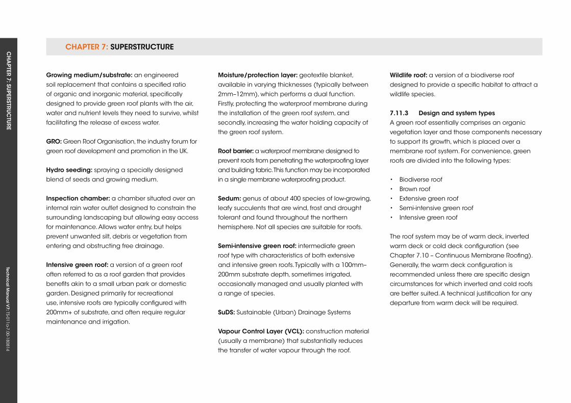
CHAPTER 7: SuPERSTRuCTuRE CH
APTER 7: Su
PERSTRuC
TuRE
Tec
hn
ica
l Ma
nua
l V7: TS-011a
-7.00-180814
growing medium/substrate: an engineered
soil replacement that contains a specified ratio
of organic and inorganic material, specifically
designed to provide green roof plants with the air,
water and nutrient levels they need to survive, whilst
facilitating the release of excess water.
gro: Green Roof Organisation, the industry forum for
green roof development and promotion in the uk.
Hydro seeding: spraying a specially designed
blend of seeds and growing medium.
inspection chamber: a chamber situated over an
internal rain water outlet designed to constrain the
surrounding landscaping but allowing easy access
for maintenance. Allows water entry, but helps
prevent unwanted silt, debris or vegetation from
entering and obstructing free drainage.
intensive green roof: a version of a green roof
often referred to as a roof garden that provides
benefits akin to a small urban park or domestic
garden. Designed primarily for recreational
use, intensive roofs are typically configured with
200mm+ of substrate, and often require regular
maintenance and irrigation.
Moisture/protection layer: geotextile blanket,
available in varying thicknesses (typically between
2mm–12mm), which performs a dual function.
Firstly, protecting the waterproof membrane during
the installation of the green roof system, and
secondly, increasing the water holding capacity of
the green roof system.
root barrier: a waterproof membrane designed to
prevent roots from penetrating the waterproofing layer
and building fabric. This function may be incorporated
in a single membrane waterproofing product.
sedum: genus of about 400 species of low-growing,
leafy succulents that are wind, frost and drought
tolerant and found throughout the northern
hemisphere. Not all species are suitable for roofs.
semi-intensive green roof: intermediate green
roof type with characteristics of both extensive
and intensive green roofs. Typically with a 100mm–
200mm substrate depth, sometimes irrigated,
occasionally managed and usually planted with
a range of species.
suDs: Sustainable (urban) Drainage Systems
vapour Control Layer (vCL): construction material
(usually a membrane) that substantially reduces
the transfer of water vapour through the roof.
Wildlife roof: a version of a biodiverse roof
designed to provide a specific habitat to attract a
wildlife species.
7.11.3 Design and system typesA green roof essentially comprises an organic
vegetation layer and those components necessary
to support its growth, which is placed over a
membrane roof system. For convenience, green
roofs are divided into the following types:
• Biodiverse roof
• Brown roof
• Extensive green roof
• Semi-intensive green roof
• Intensive green roof
The roof system may be of warm deck, inverted
warm deck or cold deck configuration (see
Chapter 7.10 – Continuous Membrane Roofing).
Generally, the warm deck configuration is
recommended unless there are specific design
circumstances for which inverted and cold roofs
are better suited. A technical justification for any
departure from warm deck will be required.
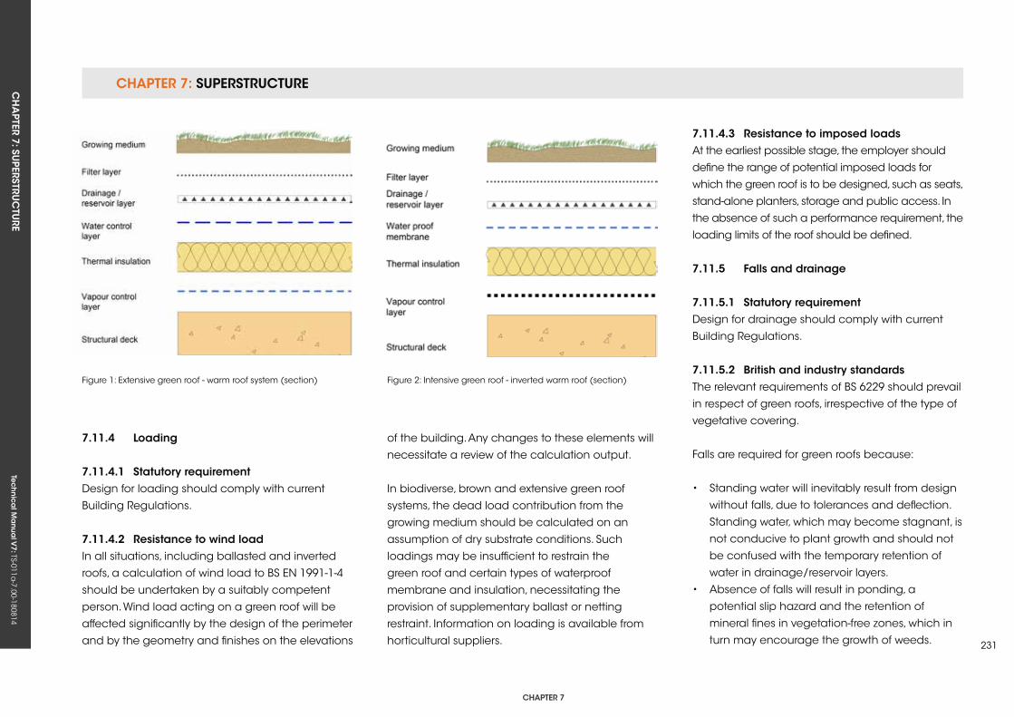
CHAPTER 7: SuPERSTRuCTuRECH
APTER 7: Su
PERSTRuC
TuRE
Tec
hn
ica
l Ma
nua
l V7: TS-011a
-7.00-180814
CHAPTER 7
231
7.11.4 Loading
7.11.4.1 statutory requirementDesign for loading should comply with current
Building Regulations.
7.11.4.2 resistance to wind loadIn all situations, including ballasted and inverted
roofs, a calculation of wind load to BS EN 1991-1-4
should be undertaken by a suitably competent
person. Wind load acting on a green roof will be
affected significantly by the design of the perimeter
and by the geometry and finishes on the elevations
Figure 1: Extensive green roof - warm roof system (section) Figure 2: Intensive green roof - inverted warm roof (section)
of the building. Any changes to these elements will
necessitate a review of the calculation output.
In biodiverse, brown and extensive green roof
systems, the dead load contribution from the
growing medium should be calculated on an
assumption of dry substrate conditions. Such
loadings may be insufficient to restrain the
green roof and certain types of waterproof
membrane and insulation, necessitating the
provision of supplementary ballast or netting
restraint. Information on loading is available from
horticultural suppliers.
7.11.4.3 resistance to imposed loadsAt the earliest possible stage, the employer should
define the range of potential imposed loads for
which the green roof is to be designed, such as seats,
stand-alone planters, storage and public access. In
the absence of such a performance requirement, the
loading limits of the roof should be defined.
7.11.5 falls and drainage
7.11.5.1 statutory requirementDesign for drainage should comply with current
Building Regulations.
7.11.5.2 British and industry standards The relevant requirements of BS 6229 should prevail
in respect of green roofs, irrespective of the type of
vegetative covering.
Falls are required for green roofs because:
• Standing water will inevitably result from design
without falls, due to tolerances and deflection.
Standing water, which may become stagnant, is
not conducive to plant growth and should not
be confused with the temporary retention of
water in drainage/reservoir layers.
• Absence of falls will result in ponding, a
potential slip hazard and the retention of
mineral fines in vegetation-free zones, which in
turn may encourage the growth of weeds.
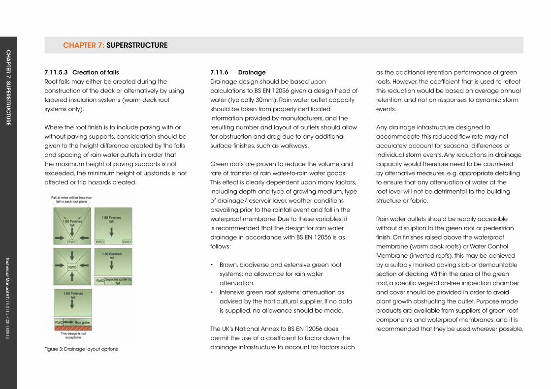
CHAPTER 7: SuPERSTRuCTuRE CH
APTER 7: Su
PERSTRuC
TuRE
Tec
hn
ica
l Ma
nua
l V7: TS-011a
-7.00-180814
7.11.5.3 Creation of fallsRoof falls may either be created during the
construction of the deck or alternatively by using
tapered insulation systems (warm deck roof
systems only).
Where the roof finish is to include paving with or
without paving supports, consideration should be
given to the height difference created by the falls
and spacing of rain water outlets in order that
the maximum height of paving supports is not
exceeded, the minimum height of upstands is not
affected or trip hazards created.
7.11.6 DrainageDrainage design should be based upon
calculations to BS EN 12056 given a design head of
water (typically 30mm). Rain water outlet capacity
should be taken from properly certificated
information provided by manufacturers, and the
resulting number and layout of outlets should allow
for obstruction and drag due to any additional
surface finishes, such as walkways.
Green roofs are proven to reduce the volume and
rate of transfer of rain water-to-rain water goods.
This effect is clearly dependent upon many factors,
including depth and type of growing medium, type
of drainage/reservoir layer, weather conditions
prevailing prior to the rainfall event and fall in the
waterproof membrane. Due to these variables, it
is recommended that the design for rain water
drainage in accordance with BS EN 12056 is as
follows:
• Brown, biodiverse and extensive green roof
systems: no allowance for rain water
attenuation.
• Intensive green roof systems: attenuation as
advised by the horticultural supplier. If no data
is supplied, no allowance should be made.
The uk’s National Annex to BS EN 12056 does
permit the use of a coefficient to factor down the
drainage infrastructure to account for factors such Figure 3: Drainage layout options
as the additional retention performance of green
roofs. However, the coefficient that is used to reflect
this reduction would be based on average annual
retention, and not on responses to dynamic storm
events.
Any drainage infrastructure designed to
accommodate this reduced flow rate may not
accurately account for seasonal differences or
individual storm events. Any reductions in drainage
capacity would therefore need to be countered
by alternative measures, e.g. appropriate detailing
to ensure that any attenuation of water at the
roof level will not be detrimental to the building
structure or fabric.
Rain water outlets should be readily accessible
without disruption to the green roof or pedestrian
finish. On finishes raised above the waterproof
membrane (warm deck roofs) or Water Control
Membrane (inverted roofs), this may be achieved
by a suitably marked paving slab or demountable
section of decking. Within the area of the green
roof, a specific vegetation-free inspection chamber
and cover should be provided in order to avoid
plant growth obstructing the outlet. Purpose made
products are available from suppliers of green roof
components and waterproof membranes, and it is
recommended that they be used wherever possible.
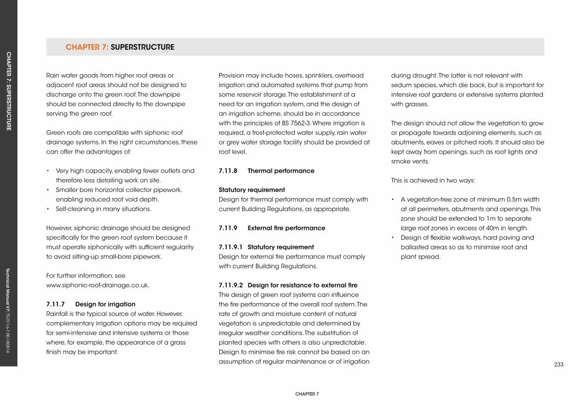
CHAPTER 7: SuPERSTRuCTuRECH
APTER 7: Su
PERSTRuC
TuRE
Tec
hn
ica
l Ma
nua
l V7: TS-011a
-7.00-180814
CHAPTER 7
233
Rain water goods from higher roof areas or
adjacent roof areas should not be designed to
discharge onto the green roof. The downpipe
should be connected directly to the downpipe
serving the green roof.
Green roofs are compatible with siphonic roof
drainage systems. In the right circumstances, these
can offer the advantages of:
• Very high capacity, enabling fewer outlets and
therefore less detailing work on site.
• Smaller bore horizontal collector pipework,
enabling reduced roof void depth.
• Self-cleaning in many situations.
However, siphonic drainage should be designed
specifically for the green roof system because it
must operate siphonically with sufficient regularity
to avoid silting-up small-bore pipework.
For further information, see
www.siphonic-roof-drainage.co.uk.
7.11.7 Design for irrigationRainfall is the typical source of water. However,
complementary irrigation options may be required
for semi-intensive and intensive systems or those
where, for example, the appearance of a grass
finish may be important.
Provision may include hoses, sprinklers, overhead
irrigation and automated systems that pump from
some reservoir storage. The establishment of a
need for an irrigation system, and the design of
an irrigation scheme, should be in accordance
with the principles of BS 7562-3. Where irrigation is
required, a frost-protected water supply, rain water
or grey water storage facility should be provided at
roof level.
7.11.8 Thermal performance
statutory requirementDesign for thermal performance must comply with
current Building Regulations, as appropriate.
7.11.9 external fire performance
7.11.9.1 statutory requirementDesign for external fire performance must comply
with current Building Regulations.
7.11.9.2 Design for resistance to external fireThe design of green roof systems can influence
the fire performance of the overall roof system. The
rate of growth and moisture content of natural
vegetation is unpredictable and determined by
irregular weather conditions. The substitution of
planted species with others is also unpredictable.
Design to minimise fire risk cannot be based on an
assumption of regular maintenance or of irrigation
during drought. The latter is not relevant with
sedum species, which die back, but is important for
intensive roof gardens or extensive systems planted
with grasses.
The design should not allow the vegetation to grow
or propagate towards adjoining elements, such as
abutments, eaves or pitched roofs. It should also be
kept away from openings, such as roof lights and
smoke vents.
This is achieved in two ways:
• A vegetation-free zone of minimum 0.5m width
at all perimeters, abutments and openings. This
zone should be extended to 1m to separate
large roof zones in excess of 40m in length.
• Design of flexible walkways, hard paving and
ballasted areas so as to minimise root and
plant spread.
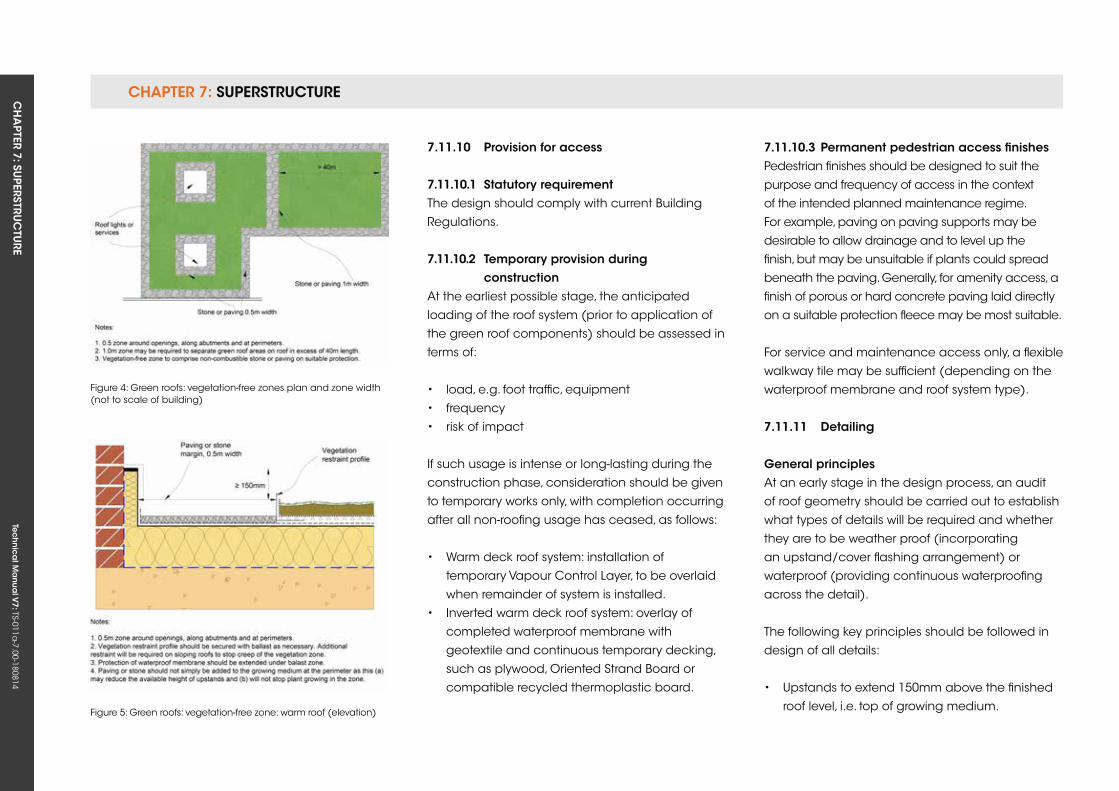
CHAPTER 7: SuPERSTRuCTuRE CH
APTER 7: Su
PERSTRuC
TuRE
Tec
hn
ica
l Ma
nua
l V7: TS-011a
-7.00-180814
Figure 5: Green roofs: vegetation-free zone: warm roof (elevation)
7.11.10 Provision for access
7.11.10.1 statutory requirementThe design should comply with current Building
Regulations.
7.11.10.2 Temporary provision during constructionAt the earliest possible stage, the anticipated
loading of the roof system (prior to application of
the green roof components) should be assessed in
terms of:
• load, e.g. foot traffic, equipment
• frequency
• risk of impact
If such usage is intense or long-lasting during the
construction phase, consideration should be given
to temporary works only, with completion occurring
after all non-roofing usage has ceased, as follows:
• Warm deck roof system: installation of
temporary Vapour Control Layer, to be overlaid
when remainder of system is installed.
• Inverted warm deck roof system: overlay of
completed waterproof membrane with
geotextile and continuous temporary decking,
such as plywood, Oriented Strand Board or
compatible recycled thermoplastic board.
7.11.10.3 Permanent pedestrian access finishesPedestrian finishes should be designed to suit the
purpose and frequency of access in the context
of the intended planned maintenance regime.
For example, paving on paving supports may be
desirable to allow drainage and to level up the
finish, but may be unsuitable if plants could spread
beneath the paving. Generally, for amenity access, a
finish of porous or hard concrete paving laid directly
on a suitable protection fleece may be most suitable.
For service and maintenance access only, a flexible
walkway tile may be sufficient (depending on the
waterproof membrane and roof system type).
7.11.11 Detailing
general principlesAt an early stage in the design process, an audit
of roof geometry should be carried out to establish
what types of details will be required and whether
they are to be weather proof (incorporating
an upstand/cover flashing arrangement) or
waterproof (providing continuous waterproofing
across the detail).
The following key principles should be followed in
design of all details:
• upstands to extend 150mm above the finished
roof level, i.e. top of growing medium.
Figure 4: Green roofs: vegetation-free zones plan and zone width (not to scale of building)
CHAPTER 7: SuPERSTRuCTuRECH
APTER 7: Su
PERSTRuC
TuRE
Tec
hn
ica
l Ma
nua
l V7: TS-011a
-7.00-180814
CHAPTER 7
235
• Downstands (of separate metal or other
flashings) should lap the upstand by a
minimum of 75mm.
• Reliance on sealant as the sole means of
protection should be avoided.
• Consideration of the effect of vegetation growth
on the integrity of the weather proofing.
The total roof zone depth should be measured from
the surface of the growing medium and assessed
at critical points, such as the top of drainage
slopes, to ensure that there is enough free upstand
available to create the minimum required 150mm
of waterproofing protection above finished roof
level. It is important that this minimum 150mm
upstand is maintained at all points around the
area of the green roof, except at continuous water
checks and at verges.
7.11.12 Design for sustainabilityAs per Chapter 7.10 – Continuous Membrane
Roofing.
7.11.13 MaterialsAs per Chapter 7.10 – Continuous Membrane
Roofing.
note: If the waterproof membrane is also intended
to provide root resistance, suitable certification of
testing in accordance with BS EN 13948 should be
available.
7.11.14 installation
7.11.14.1 Protection of the roof
Temporary protection (during construction)Responsibility for temporary protection and a
method statement for its use should be agreed
prior to commencement of works. Suitable
materials should be selected in consultation with
membrane manufacturers as appropriate, for
example:
• Linked recycled thermoplastic sheets
• Rolled recycled thermoplastic or elastomeric
sheets
Particular consideration should be given to
locations of concentrated access, such as step-out
areas onto the roof or where wheeled equipment
may be used.
Permanent protection (during service)See 7.11.14.1 (above).
7.11.14.2 vapour Control Layer (vCL)As per Chapter 7.10 – Continuous Membrane
Roofing.
7.11.14.3 Thermal insulationAs per Chapter 7.10 – Continuous Membrane
Roofing.
7.11.14.4 Waterproof membraneAs per Chapter 7.10 – Continuous Membrane
Roofing.
note: Warm roof systems – restraint against wind
load. It is unusual for the installation of ballast and
green roof components to follow immediately after
installation of the roof system. This may be because
the roof system and green roof overlay are to be
installed by different contractors, or because of
site factors, such as limited storage. unless it is
sequenced to do so, the roof system should be
installed with restraint against wind load based
on an assumption of an exposed waterproof
membrane.
7.11.15 Testing
7.11.15.1 final inspectionA thorough, recorded, visual inspection of all
areas, including details, should be carried out, with
representation from the General Contractor and
Roofing Contractor in attendance.
7.11.15.2 Procurement of testing servicesThe waterproof membrane should be tested
for integrity before the application of any
other components above it. Testing should be
undertaken by a third-party that is independent of
the roofing contract. The testing service provider
should provide evidence of the following:
CHAPTER 7: SuPERSTRuCTuRE CH
APTER 7: Su
PERSTRuC
TuRE
Tec
hn
ica
l Ma
nua
l V7: TS-011a
-7.00-180814
• Efficacy of the method proposed in the
circumstances of the project.
• Experience and training of operator.
• Membership of an appropriate trade
association that sets a Code of Conduct for
the service.
7.11.15.3 Methods of test
Low voltage earth leakageLow voltage earth leakage is a safe and effective
method for the testing of waterproofing integrity
in roofs where the waterproof membrane is an
electrical insulator and the deck provides an
electrical earth. It is not suitable for testing flat
roofs where the waterproof membrane has been
overlaid with insulation and ballast (inverted roofs)
or ballast only (ballasted warm roofs); therefore,
testing should be carried out prior to completion of
the roofing system.
High voltage electrical discharge The high voltage electrical discharge method is
best suited to the testing of continuous thin films,
such as liquid-applied coatings. Its use is not
recommended with polymeric single ply, reinforced
bitumen membranes and mastic asphalt.
vacuum Vacuum testing of seams of membranes
manufactured off-site is an effective means of
quality assessment, but is not recommended as a
method of demonstrating the integrity of flat roofs.
flood testingFlood testing is a suitable method of demonstrating
the integrity of small areas of roof to which a green
roof system is to be applied. However, consideration
should be given to the effect of ingress on
programme and the risk of entrapped water in
insulation (warm deck roofs) and decks (all types).
The area under any one test should not exceed
50m2.
7.11.15.4 Testing after installation of a green roof systemNo reliable method is available for testing the
integrity of a green roof following application
of the green roof components. With extensive
greening on certain warm roof systems, it may be
feasible to use low voltage earth leakage, but any
defects recorded will in any case involve removal
of the green roof components. Therefore, it is
strongly recommended to ensure the very highest
possible standards of protection of the waterproof
membrane during the application of the green
roof components.
7.11.16 Provision of information
7.11.16.1 operation and Maintenance Manual The following information is required:
• Specification, as-built:
- Waterproof membrane: generic type,
product(s) and (as appropriate) thickness.
- Thermal insulation: generic type, product(s)
and thickness.
- Acoustic insulation: generic type, product
and (as appropriate) thickness.
- Vapour Control Layer: generic type, product
(as appropriate) and thickness (as
appropriate).
- Rain water outlets: type, product, capacity,
location and means of access.
• Procedure for maintenance of waterproof
membrane, including (where appropriate)
recommended frequency and method of
application of solar reflective finish.
• Procedure for repair of waterproof membrane.
• Instructions for irrigation (method/frequency),
weed control and application of fertiliser
(type/season/frequency).

Tec
hn
ica
l Ma
nua
l V6: TS-011a
-6.00-010413Te
ch
nic
al M
anu
al V
7: TS-011a-7.00-180814
FUNCTIONAL REQUIREMENTS
237
7.12 roof Coverings – MeTAL DeCk roofing
Workmanshipi. All workmanship must be within the tolerances defined in Chapter 1
of this Manual.
ii. All work is to be carried out by a technically competent person in
a workmanlike manner.
iii. Certification is required for any work completed by an approved
installer.
Materialsi. All materials should be stored correctly in a manner that will not cause
damage or deterioration of the product.
ii. All materials, products and building systems shall be appropriate and
suitable for their intended purpose.
iii. The structure shall, unless specifically agreed otherwise with the
Warranty provider, have a life of not less than 60 years. Individual
components and assemblies, not integral to the structure, may have
a lesser durability, but not in any circumstances less than 15 years.
Designi. The design and specifications shall provide a clear indication of the
design intent and demonstrate a satisfactory level of performance.
ii. Roof coverings must prevent any external moisture passing into the
internal environment of the dwelling.
iii. Structural elements outside the parameters of regional Approved
Documents must be supported by structural calculations provided by
a suitably qualified expert.
iv. The materials, design and construction must meet the relevant
Building Regulations, British Standards, Eurocodes and other statutory
requirements.
CHAPTer 7

CHAPTER 7: SuPERSTRuCTuRE CH
APTER 7: Su
PERSTRuC
TuRE
Tec
hn
ica
l Ma
nua
l V7: TS-011a
-7.00-180814
7.12.1 introductionMetal roofing is usually built to a decent standard,
but occasionally there are problems, especially
where site workmanship has not been up to
standard.
7.12.2 Double skin insulated roofs
7.12.2.1 What is a double skin insulated roof?A double skin insulated roof is made-up on-site
from separate components generally comprising:
liner sheet, Vapour Control Layer (VCL), spacer
system, insulation, breather membrane and
finished externally with top weathering sheets.
Top weathering sheets are generally secret fixed
onto clips or standing seam sheets onto halters,
these being machine seamed once fixed. Pierce
fixed sheets are still widely used, which are fixed
directly to the spacer system with external visible
fixings.
Figure 1: Typical metal double skin insulated roof
Liner sheets can be solid or perforated to give an acoustic, sound-deadening roof. They are fixed directly to purlins, and can act as a VCL if a separate vapour barrier is not specified. If the liner is not used as a VCL, a reinforced vapour control sheet should be incorporated within the roof.
Insulation must be installed between the VCL and the top weathering sheet; some systems may require ventilation above the insulation and others may not; it varies from manufacturer to manufacturer. Where there is no requirement to ventilate, the insulation should be compressed slightly to ensure that there are no air voids where condensation may occur.
7.12.2.2 Workmanship
Top weathering sheetsEnsure that the top weathering sheets are installed in accordance with the manufacturer’s instructions.
These must be long enough to discharge into the gutter correctly and allow for an eaves angle if required by the system.
Check that end and side lap tape sizes conform to the manufacturer’s requirements.
For pierce fixed trapezoidal sheets, check for tell tales to end laps and side laps for the correct
number of rows of tape.
Liner sheetsWhere the liner sheet is solid and used as a vapour
check, note the following:
• Frequency of main fixings to purlins and
frequency of side lap stitchers.
• End laps to be sealed with mastic tape; check
the size and that this is continuous. Side laps
have a wider 50mm Polyband tape placed from
the inside so this is visible from above.
• Check for cuts or splits in this metal liner.
• Ensure that to eaves and ridge the correct
filler blocks have been used, bedded in mastic;
if necessary, a closure flashing must be used
from the crown of the sheet to the wall junction
to maintain a vapour check. Check the use of
sealant tapes and fire-retardant foam.
separate vapour Control Layer (vCL)This should be a reinforced sheet, and is used
to ensure a more positive air seal around the
perimeter of the building. The vapour check
should be sealed in the field area with the correct
tape, with the number of rows dependant on the
application. Check the integrity of these tapes
and that they are continuous and correctly
joined. Where the vapour check abuts the walls
to the verge or eaves, it must be properly sealed
in accordance with the Architect’s detail. Around
penetrations, the vapour check must be cut and
sealed to any pipes or upstands.
CHAPTER 7: SuPERSTRuCTuRECH
APTER 7: Su
PERSTRuC
TuRE
Tec
hn
ica
l Ma
nua
l V7: TS-011a
-7.00-180814
CHAPTER 7
239
The spacer system is fixed through the vapour
check and liner into the purlins. The spacer system
will have a soft sealing pad to ensure the vapour
check is maintained around the fixing.
Check for punctures of the vapour check by foot
traffic or damage, and patch as required.
insulationCheck the packaging to ensure that the correct
thickness is being used if one layer is used, or a
combination of thicknesses to give the correct
specified thickness. For two thicknesses or more,
check that all joints are staggered and check the
Lambda value against the specification.
Ensure that no packaging or debris is left in the
roof void prior to or during the installation of the
insulation. The insulation should fill the void or be
compressed into the void; there should be no
slumping or gaps and it should be packed into
voids at the junctions of the ridge and verge.
With standing seam roofs, a rigid mineral slab
insulation should be placed at eaves, ridge and
around all penetrations and walkways to support
the vulnerable areas of the roof, which will give a
solid support to the roof sheet pans. This is easy
to see during construction and easily felt on
completion. The supported pan of the sheet feels
solid to walk on.
support systemCheck the frequency of brackets against the
specification and the number of fixings per bracket,
and that they are the correct type of fixing.
With standing seam roofs, the halter may be fixed
with a stainless steel fixing; check the type and
frequency of fixing. Check the orientation of the
halter in relation to the lay of the sheet, i.e. will they
pick up the seam, as there is a right and wrong
way round for halters.
Manufacturers provide halter templates to set out
halters, and there must be one on-site to obtain the
correct gauging of the halters.
roof penetrationsThese must be sealed to maintain the VCL.
Where the liner is used as a VCL, the metal-to-
metal junction must be sealed with fire-retardant
foam. With a separate VCL, this must be sealed
to the upstand or pipes with the appropriate
tape. Externally with aluminium roof sheets, the
junctions with penetrations should be site welded
or weathered using glass reinforced plastic (GRP)
in-situ weathering.
roof lightsStanding seam roof sheets are usually on separate
insulated upstands. With pierce fixed trapezoidal
roof sheets, roof lights are in line, either factory or
site assembled. Ensure that the correct size of tape
is used, check the number of rows of tape that are
required and that side lap tapes are not twisted by
fasteners.
generalCheck surface finishes for abrasions, dents and
cuts, and that the roof has not been used as a
cutting surface for flashings or other metal. Hot
swarf from angle grinders burns into the plastisol
coating of steel sheets, marks aluminium and
rapidly turns to rust. Flashings should have sufficient
overlap or butt straps, 150mm wide, and be sealed
and supported. Check the frequency of fixings and
that they are of the correct type.
7.12.3 Composite panel metal roofing
7.12.3.1 What is a composite panel roof?A simple sheet roof system with ensured insulation
thickness that is delivered with the top weathering
sheet, insulation and white liner all in one sheet.
With the increase in insulation, thickness panels
are being made shorter in length so they can be
handled into position. This means that there are
more end laps to be checked.
The standard manufacturer’s details are to be
adhered to, but the following need to be checked.
CHAPTER 7: SuPERSTRuCTuRE CH
APTER 7: Su
PERSTRuC
TuRE
Tec
hn
ica
l Ma
nua
l V7: TS-011a
-7.00-180814
7.12.3.2 Workmanship and installation
fixingsThere may be a requirement for stainless steel
fixings to be used. Check by inspecting boxes and
use a magnet; drill points will be magnetic only.
Check fixings are suitable for the purlin type – steel,
light gauge cold rolled, heavy gauge or timber –
as all fixings are different.
Check the bearing area of the purlin; if the building
is not square, the sheets will run out and the
end lap detail will not be supported. This can be
overcome by using a galvanised support that is
fixed to the purlin and which supports the end lap.
Check that the right number of fixings has been
used for the panel and the frequency of side lap
stitchers; ensure that they are side lap stitchers and
not main fixings.
sealant tapesCheck the number of rows required by the
manufacturer of the panel for end laps. Tell tales
should be visible at side laps of each sheet. Tell
tales are the ends of the mastic tape run that can
be seen or must be felt for at the side of each
sheet. The same applies to side laps; there should
be a tell tale at the end of the sheet. use the end of
a hacksaw blade to locate the rows of mastic tape.
On roof lights, mastic tape is visible; check
its location, that its size complies with the
manufacturer’s requirements and that there are the
correct number of rows. Tape should not be twisted
by the fixings.
Air tightnessThere must be a supply of gun foam, fire rated,
at roof level for filling in voids before flashings
are fixed. If there is not one on site, air tightness
and maintaining the insulation cannot be fully
achieved.
The use of foam needs to be inspected during
the course of construction, and internal tapes to
eaves and ridge purlins need to be inspected for
size and position. At the ridge, the gap between
panels needs to be filled with foam to maintain the
insulation and prevent condensation forming. There
also needs to be a suitably sealed inner ridge.
Verge details are difficult and it may be necessary
for an internal verge to be cut and sealed around
purlins. Check sealant tapes and the use of gun
foam to maintain insulation. The manufacturer’s
details may not be achievable, but an alternative
must be devised to maintain air tightness. A degree
of confidence in this requirement should be shown
on-site as an indication of the importance of air
tightness and how this can be achieved.
gutter junctionsIf parapet or valley gutters are being used, check
the air seal at the junction of the two. Gutter joints
are not always level, and any gaps have to be
filled. This will not only prevent wind-driven rain from
entering the building, but will also maintain an air
seal.
Check that roof sheets are oversailing into the
gutter correctly.
roof penetrationsPenetrations such as flues, vents, upstand-type roof
lights and sun tubes need to be sealed internally,
the insulation being maintained with site-applied
foam. Externally, upstands must be weathered
correctly and, with steel composite sheets, this is
best achieved using GRP in-situ weathering.
generalCheck surface finish for cuts and abrasions.
Check that the roof has not been used as a
cutting surface for flashings or other metal. Hot
swarf from angle grinders burns into the plastisol
coating and rapidly turns to rust.
Flashings should have a sufficient overlap and be
sealed and supported. Check the frequency of
fixings and that they are of the right type.
CHAPTER 7: SuPERSTRuCTuRECH
APTER 7: Su
PERSTRuC
TuRE
Tec
hn
ica
l Ma
nua
l V7: TS-011a
-7.00-180814
CHAPTER 7
241
Check for closure from gutters and sheet oversails.
There should be suitable shrouds to prevent birds or
vermin from getting into the building, which can be
often overlooked.
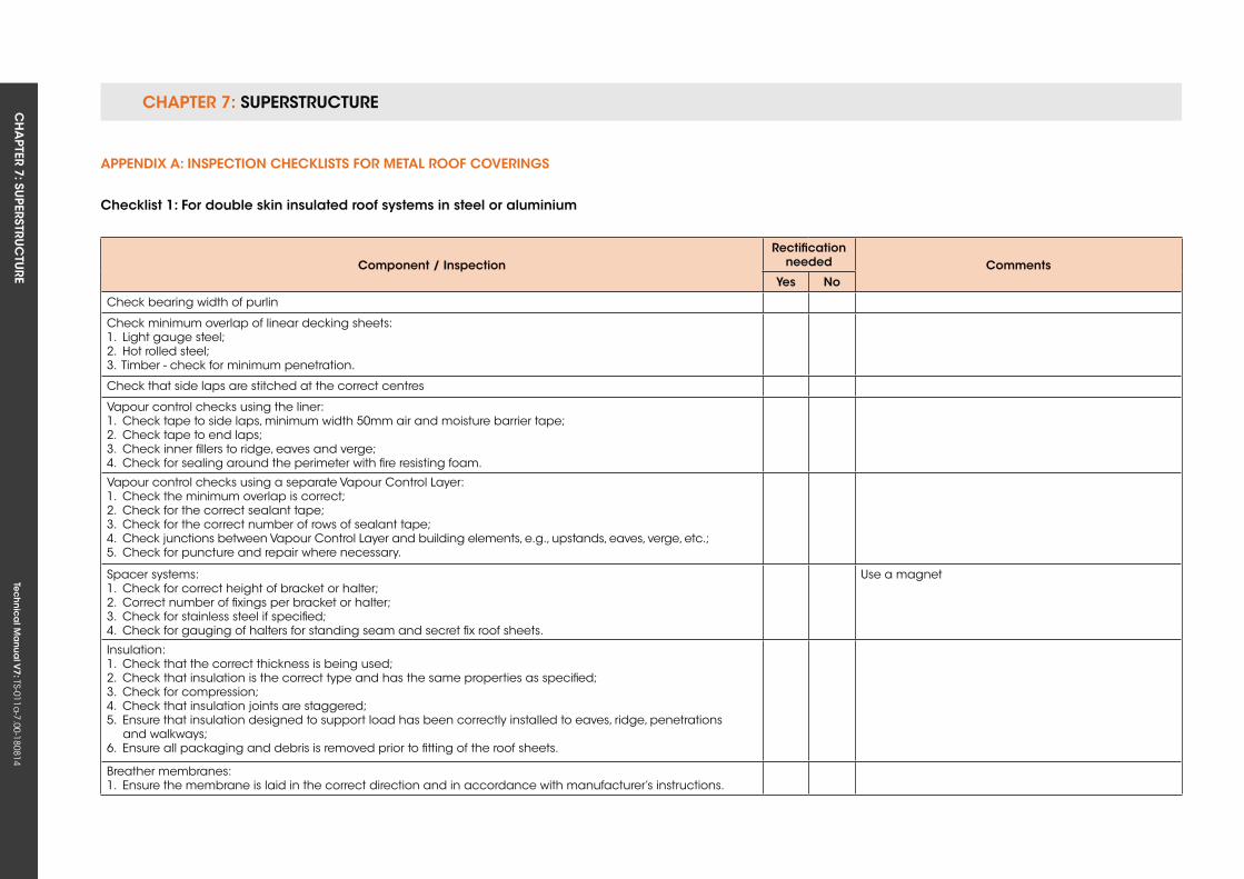
CHAPTER 7: SuPERSTRuCTuRE CH
APTER 7: Su
PERSTRuC
TuRE
Tec
hn
ica
l Ma
nua
l V7: TS-011a
-7.00-180814
APPenDix A: insPeCTion CHeCkLisTs for MeTAL roof Coverings
Checklist 1: for double skin insulated roof systems in steel or aluminium
Component / inspectionrectification
needed Commentsyes no
Check bearing width of purlin
Check minimum overlap of linear decking sheets:1. Light gauge steel;2. Hot rolled steel;3. Timber - check for minimum penetration.
Check that side laps are stitched at the correct centres
Vapour control checks using the liner:1. Check tape to side laps, minimum width 50mm air and moisture barrier tape;2. Check tape to end laps;3. Check inner fillers to ridge, eaves and verge;4. Check for sealing around the perimeter with fire resisting foam.
Vapour control checks using a separate Vapour Control Layer:1. Check the minimum overlap is correct;2. Check for the correct sealant tape;3. Check for the correct number of rows of sealant tape;4. Check junctions between Vapour Control Layer and building elements, e.g., upstands, eaves, verge, etc.;5. Check for puncture and repair where necessary.
Spacer systems:1. Check for correct height of bracket or halter;2. Correct number of fixings per bracket or halter;3. Check for stainless steel if specified;4. Check for gauging of halters for standing seam and secret fix roof sheets.
use a magnet
Insulation:1. Check that the correct thickness is being used;2. Check that insulation is the correct type and has the same properties as specified;3. Check for compression;4. Check that insulation joints are staggered;5. Ensure that insulation designed to support load has been correctly installed to eaves, ridge, penetrations and walkways;6. Ensure all packaging and debris is removed prior to fitting of the roof sheets.
Breather membranes:1. Ensure the membrane is laid in the correct direction and in accordance with manufacturer’s instructions.
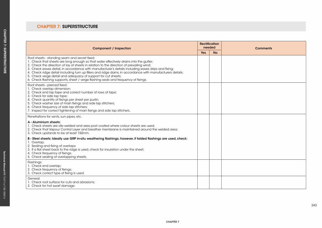
CHAPTER 7: SuPERSTRuCTuRECH
APTER 7: Su
PERSTRuC
TuRE
Tec
hn
ica
l Ma
nua
l V7: TS-011a
-7.00-180814
CHAPTER 7
243
Component / inspectionrectification
needed Commentsyes no
Roof sheets - standing seam and secret fixed:1. Check that sheets are long enough so that water effectively drains into the gutter;2. Check the direction of lay of sheets in relation to the direction of prevailing wind;3. Check eaves detail, in accordance with manufacturer’s details including eaves drips and fixing;4. Check ridge detail including turn up fillers and ridge dams, in accordance with manufacturers details;5. Check verge detail and adequacy of support for cut sheets;6. Check flashing supports, sheet / verge flashing seals and frequency of fixings.
Roof sheets - pierced fixed:1. Check overlap dimension;2. Check end lap tape and correct number of rows of tape;3. Check for side lap tape;4. Check quantity of fixings per sheet per purlin;5. Check washer size of main fixings and side lap stitchers;6. Check frequency of side lap stitchers;7. Inspect for correct tightening of main fixings and side lap stitchers.
Penetrations for vents, sun pipes, etc.
A - Aluminium sheets:1. Check sheets are site welded and area post coated where colour sheets are used;2. Check that Vapour Control Layer and breather membrane is maintained around the welded area;3. Check upstands to be at least 150mm.
B - steel sheets: ideally use grP in-situ weathering flashings; however, if folded flashings are used, check:1. Overlap;2. Sealing and fixing of overlaps;3. If a flat sheet back to the ridge is used, check for insulation under the sheet;4. Check frequency of fixings;5. Check sealing of overlapping sheets.
Flashings:1. Check end overlap;2. Check frequency of fixings;3. Check correct type of fixing is used.
General1. Check roof surface for cuts and abrasions;2. Check for hot swarf damage.
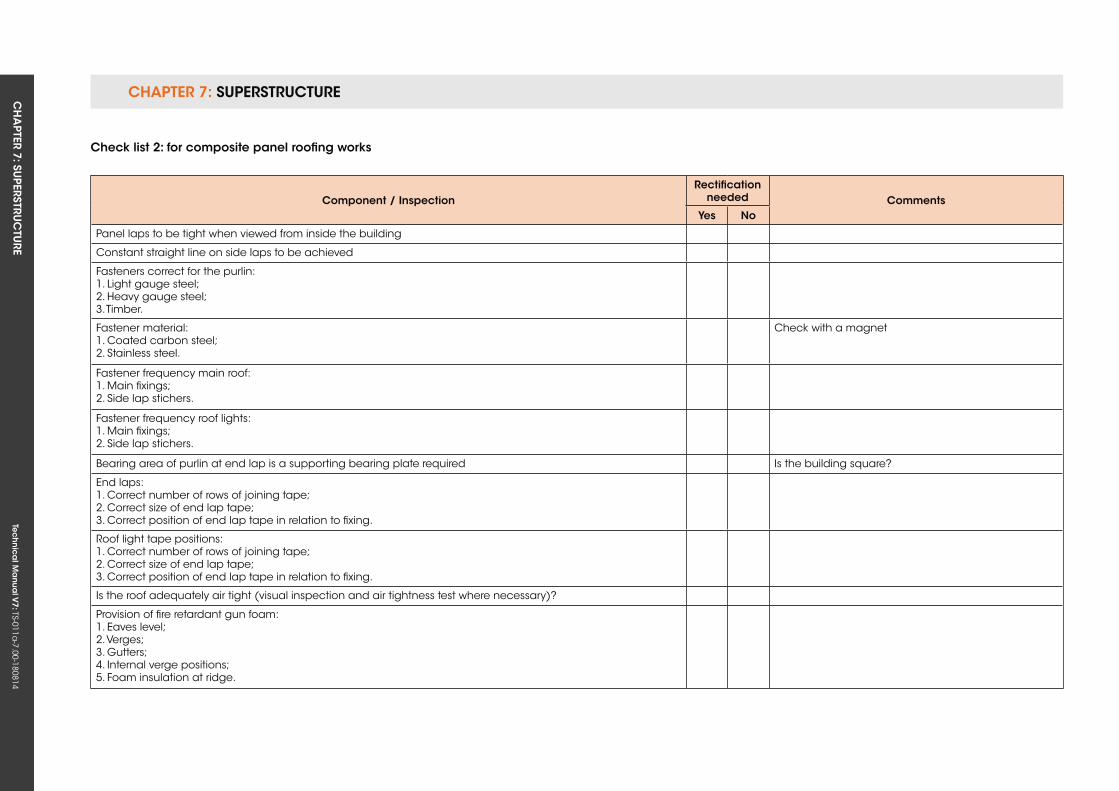
CHAPTER 7: SuPERSTRuCTuRE CH
APTER 7: Su
PERSTRuC
TuRE
Tec
hn
ica
l Ma
nua
l V7: TS-011a
-7.00-180814
Check list 2: for composite panel roofing works
Component / inspectionrectification
needed Commentsyes no
Panel laps to be tight when viewed from inside the building
Constant straight line on side laps to be achieved
Fasteners correct for the purlin: 1. Light gauge steel;2. Heavy gauge steel;3. Timber.
Fastener material:1. Coated carbon steel;2. Stainless steel.
Check with a magnet
Fastener frequency main roof:1. Main fixings;2. Side lap stichers.
Fastener frequency roof lights:1. Main fixings;2. Side lap stichers.
Bearing area of purlin at end lap is a supporting bearing plate required Is the building square?
End laps:1. Correct number of rows of joining tape;2. Correct size of end lap tape;3. Correct position of end lap tape in relation to fixing.
Roof light tape positions:1. Correct number of rows of joining tape;2. Correct size of end lap tape;3. Correct position of end lap tape in relation to fixing.
Is the roof adequately air tight (visual inspection and air tightness test where necessary)?
Provision of fire retardant gun foam:1. Eaves level;2. Verges;3. Gutters;4. Internal verge positions;5. Foam insulation at ridge.
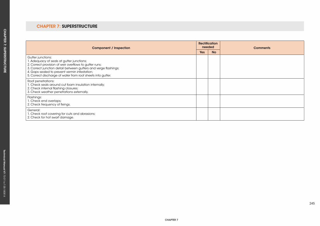
CHAPTER 7: SuPERSTRuCTuRECH
APTER 7: Su
PERSTRuC
TuRE
Tec
hn
ica
l Ma
nua
l V7: TS-011a
-7.00-180814
CHAPTER 7
245
Component / inspectionrectification
needed Commentsyes no
Gutter junctions:1. Adequacy of seals at gutter junctions;2. Correct provision of weir overflows to gutter runs;3. Correct junction detail between gutters and verge flashings;4. Gaps sealed to prevent vermin infestation;5. Correct discharge of water from roof sheets into gutter.
Roof penetrations:1. Check seals around cut foam insulation internally;2. Check internal flashing closures;3. Check weather penetrations externally.
Flashings:1. Check end overlaps;2. Check frequency of fixings.
General:1. Check roof covering for cuts and abrasions;2. Check for hot swarf damage.

Tec
hn
ica
l Ma
nua
l V6: TS-011a
-6.00-010413Te
ch
nic
al M
anu
al V
7: TS-011a-7.00-180814

CH
APTER 8: SU
PERSTRUC
TURE (IN
TERNA
L) Te
ch
nic
al M
anu
al V
7: TS-011a-7.00-180814
CHAPTER 8
247
CHAPTer 8: suPersTruCTure (inTernAL)
ConTenTs
8.1 INTERNAL WALLS
8.2 uPPER FLOORS
8.3 STAIRS
8.4 FIRE STOPPING AND FIRE PROTECTION TO FLATS AND APARTMENTS
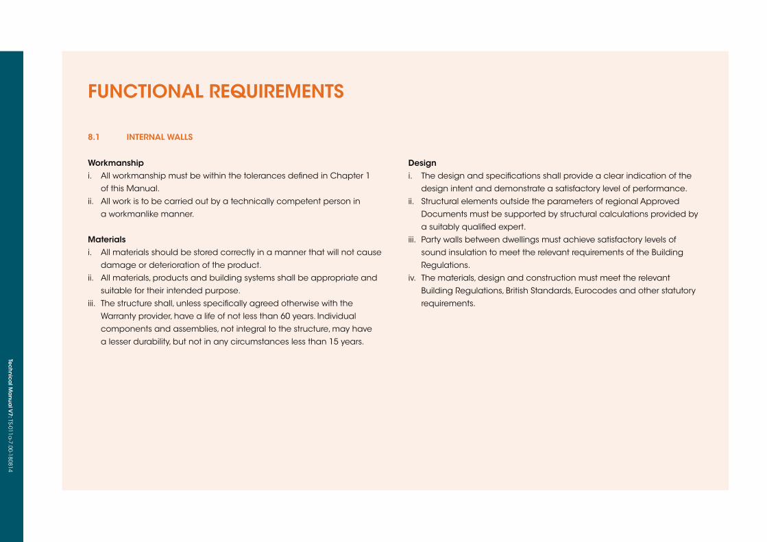
Tec
hn
ica
l Ma
nua
l V6: TS-011a
-6.00-010413Te
ch
nic
al M
anu
al V
7: TS-011a-7.00-180814
FUNCTIONAL REQUIREMENTS
8.1 inTernAL WALLs
Workmanshipi. All workmanship must be within the tolerances defined in Chapter 1
of this Manual.
ii. All work is to be carried out by a technically competent person in
a workmanlike manner.
Materialsi. All materials should be stored correctly in a manner that will not cause
damage or deterioration of the product.
ii. All materials, products and building systems shall be appropriate and
suitable for their intended purpose.
iii. The structure shall, unless specifically agreed otherwise with the
Warranty provider, have a life of not less than 60 years. Individual
components and assemblies, not integral to the structure, may have
a lesser durability, but not in any circumstances less than 15 years.
Designi. The design and specifications shall provide a clear indication of the
design intent and demonstrate a satisfactory level of performance.
ii. Structural elements outside the parameters of regional Approved
Documents must be supported by structural calculations provided by
a suitably qualified expert.
iii. Party walls between dwellings must achieve satisfactory levels of
sound insulation to meet the relevant requirements of the Building
Regulations.
iv. The materials, design and construction must meet the relevant
Building Regulations, British Standards, Eurocodes and other statutory
requirements.
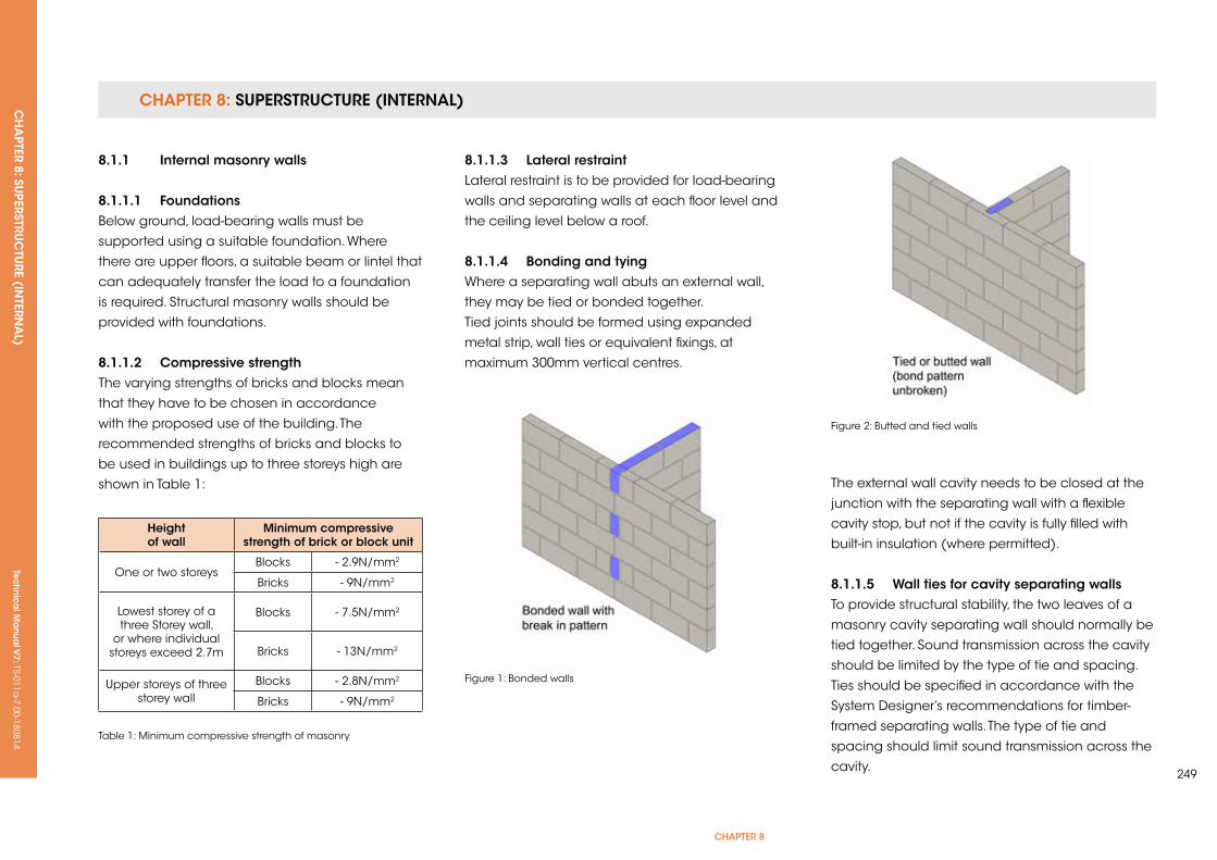
CHAPTER 8: SUPERSTRUCTURE (INTERNAL) CH
APTER 8: SU
PERSTRUC
TURE (IN
TERNA
L) Te
ch
nic
al M
anu
al V
7: TS-011a-7.00-180814
CHAPTER 8
249
8.1.1 internal masonry walls
8.1.1.1 foundationsBelow ground, load-bearing walls must be
supported using a suitable foundation. Where
there are upper floors, a suitable beam or lintel that
can adequately transfer the load to a foundation
is required. Structural masonry walls should be
provided with foundations.
8.1.1.2 Compressive strengthThe varying strengths of bricks and blocks mean
that they have to be chosen in accordance
with the proposed use of the building. The
recommended strengths of bricks and blocks to
be used in buildings up to three storeys high are
shown in Table 1:
Height of wall
Minimum compressive strength of brick or block unit
One or two storeysBlocks - 2.9N/mm2
Bricks - 9N/mm2
Lowest storey of a three Storey wall,
or where individual storeys exceed 2.7m
Blocks - 7.5N/mm2
Bricks - 13N/mm2
upper storeys of threestorey wall
Blocks - 2.8N/mm2
Bricks - 9N/mm2
Table 1: Minimum compressive strength of masonry
8.1.1.3 Lateral restraintLateral restraint is to be provided for load-bearing
walls and separating walls at each floor level and
the ceiling level below a roof.
8.1.1.4 Bonding and tyingWhere a separating wall abuts an external wall,
they may be tied or bonded together.
Tied joints should be formed using expanded
metal strip, wall ties or equivalent fixings, at
maximum 300mm vertical centres.
The external wall cavity needs to be closed at the
junction with the separating wall with a flexible
cavity stop, but not if the cavity is fully filled with
built-in insulation (where permitted).
8.1.1.5 Wall ties for cavity separating wallsTo provide structural stability, the two leaves of a
masonry cavity separating wall should normally be
tied together. Sound transmission across the cavity
should be limited by the type of tie and spacing.
Ties should be specified in accordance with the
System Designer’s recommendations for timber-
framed separating walls. The type of tie and
spacing should limit sound transmission across the
cavity.
Figure 1: Bonded walls
Figure 2: Butted and tied walls
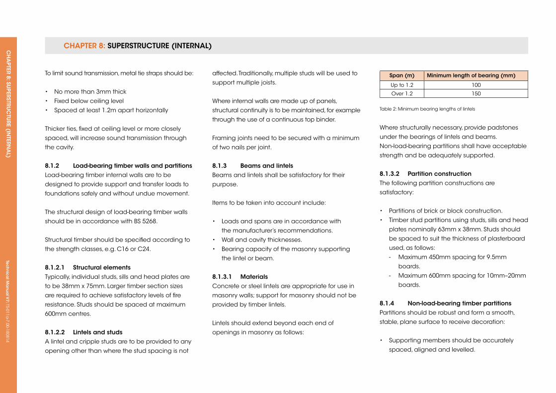
CHAPTER 8: SUPERSTRUCTURE (INTERNAL) CH
APTER 8: SU
PERSTRUC
TURE (IN
TERNA
L) Te
ch
nic
al M
anu
al V
7: TS-011a-7.00-180814
To limit sound transmission, metal tie straps should be:
• No more than 3mm thick
• Fixed below ceiling level
• Spaced at least 1.2m apart horizontally
Thicker ties, fixed at ceiling level or more closely
spaced, will increase sound transmission through
the cavity.
8.1.2 Load-bearing timber walls and partitionsLoad-bearing timber internal walls are to be
designed to provide support and transfer loads to
foundations safely and without undue movement.
The structural design of load-bearing timber walls
should be in accordance with BS 5268.
Structural timber should be specified according to
the strength classes, e.g. C16 or C24.
8.1.2.1 structural elementsTypically, individual studs, sills and head plates are
to be 38mm x 75mm. Larger timber section sizes
are required to achieve satisfactory levels of fire
resistance. Studs should be spaced at maximum
600mm centres.
8.1.2.2 Lintels and studsA lintel and cripple studs are to be provided to any
opening other than where the stud spacing is not
affected. Traditionally, multiple studs will be used to
support multiple joists.
Where internal walls are made up of panels,
structural continuity is to be maintained, for example
through the use of a continuous top binder.
Framing joints need to be secured with a minimum
of two nails per joint.
8.1.3 Beams and lintelsBeams and lintels shall be satisfactory for their
purpose.
Items to be taken into account include:
• Loads and spans are in accordance with
the manufacturer’s recommendations.
• Wall and cavity thicknesses.
• Bearing capacity of the masonry supporting
the lintel or beam.
8.1.3.1 MaterialsConcrete or steel lintels are appropriate for use in
masonry walls; support for masonry should not be
provided by timber lintels.
Lintels should extend beyond each end of
openings in masonry as follows:
span (m) Minimum length of bearing (mm)
up to 1.2 100
Over 1.2 150
Table 2: Minimum bearing lengths of lintels
Where structurally necessary, provide padstones
under the bearings of lintels and beams.
Non-load-bearing partitions shall have acceptable
strength and be adequately supported.
8.1.3.2 Partition constructionThe following partition constructions are
satisfactory:
• Partitions of brick or block construction.
• Timber stud partitions using studs, sills and head
plates nominally 63mm x 38mm. Studs should
be spaced to suit the thickness of plasterboard
used, as follows:
- Maximum 450mm spacing for 9.5mm
boards.
- Maximum 600mm spacing for 10mm–20mm
boards.
8.1.4 non-load-bearing timber partitionsPartitions should be robust and form a smooth,
stable, plane surface to receive decoration:
• Supporting members should be accurately
spaced, aligned and levelled.
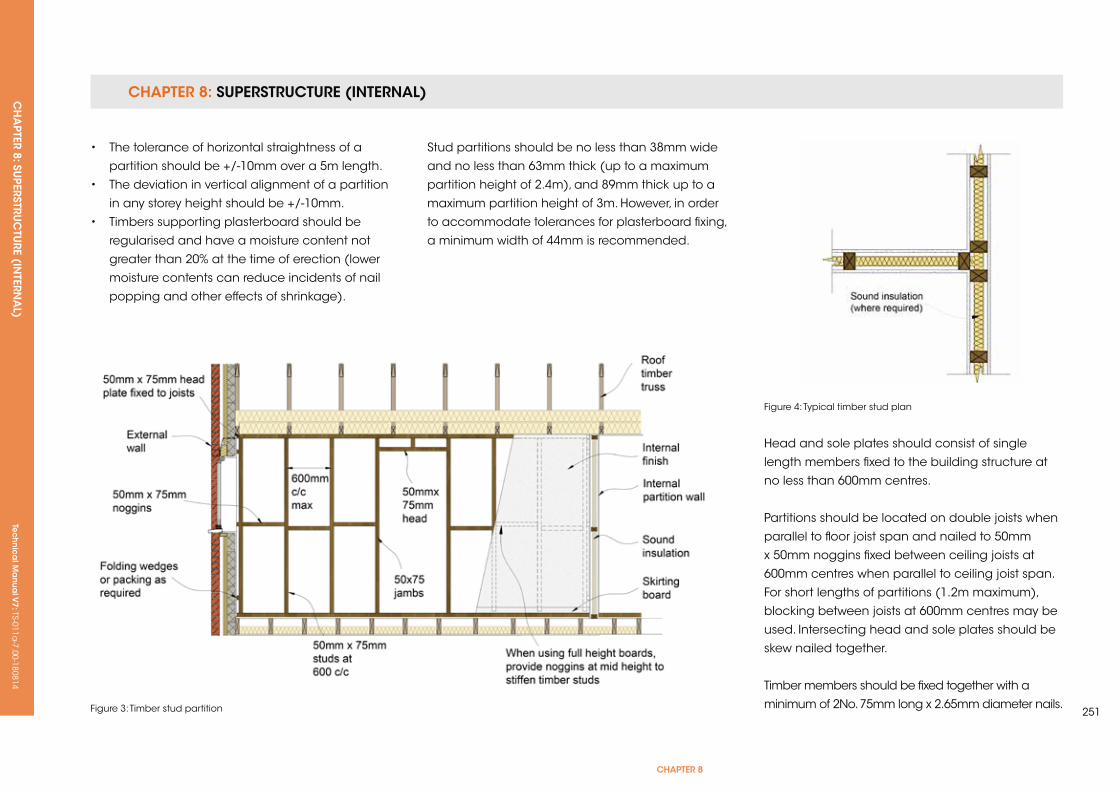
CHAPTER 8: SUPERSTRUCTURE (INTERNAL) CH
APTER 8: SU
PERSTRUC
TURE (IN
TERNA
L) Te
ch
nic
al M
anu
al V
7: TS-011a-7.00-180814
CHAPTER 8
251
• The tolerance of horizontal straightness of a
partition should be +/-10mm over a 5m length.
• The deviation in vertical alignment of a partition
in any storey height should be +/-10mm.
• Timbers supporting plasterboard should be
regularised and have a moisture content not
greater than 20% at the time of erection (lower
moisture contents can reduce incidents of nail
popping and other effects of shrinkage).
Stud partitions should be no less than 38mm wide
and no less than 63mm thick (up to a maximum
partition height of 2.4m), and 89mm thick up to a
maximum partition height of 3m. However, in order
to accommodate tolerances for plasterboard fixing,
a minimum width of 44mm is recommended.
Figure 3: Timber stud partition
Head and sole plates should consist of single
length members fixed to the building structure at
no less than 600mm centres.
Partitions should be located on double joists when
parallel to floor joist span and nailed to 50mm
x 50mm noggins fixed between ceiling joists at
600mm centres when parallel to ceiling joist span.
For short lengths of partitions (1.2m maximum),
blocking between joists at 600mm centres may be
used. Intersecting head and sole plates should be
skew nailed together.
Timber members should be fixed together with a
minimum of 2No. 75mm long x 2.65mm diameter nails.
Figure 4: Typical timber stud plan
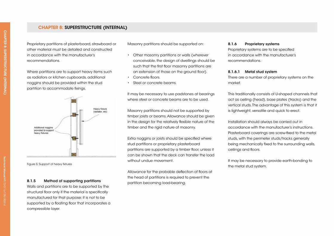
CHAPTER 8: SUPERSTRUCTURE (INTERNAL) CH
APTER 8: SU
PERSTRUC
TURE (IN
TERNA
L) Te
ch
nic
al M
anu
al V
7: TS-011a-7.00-180814
Proprietary partitions of plasterboard, strawboard or
other material must be detailed and constructed
in accordance with the manufacturer’s
recommendations.
Where partitions are to support heavy items such
as radiators or kitchen cupboards, additional
noggins should be provided within the stud
partition to accommodate fixings.
8.1.5 Method of supporting partitionsWalls and partitions are to be supported by the
structural floor only if the material is specifically
manufactured for that purpose; it is not to be
supported by a floating floor that incorporates a
compressible layer.
Figure 5: Support of heavy fixtures
Masonry partitions should be supported on:
• Other masonry partitions or walls (wherever
conceivable, the design of dwellings should be
such that the first floor masonry partitions are
an extension of those on the ground floor).
• Concrete floors.
• Steel or concrete beams.
It may be necessary to use padstones at bearings
where steel or concrete beams are to be used.
Masonry partitions should not be supported by
timber joists or beams. Allowance should be given
in the design for the relatively flexible nature of the
timber and the rigid nature of masonry.
Extra noggins or joists should be specified where
stud partitions or proprietary plasterboard
partitions are supported by a timber floor, unless it
can be shown that the deck can transfer the load
without undue movement.
Allowance for the probable deflection of floors at
the head of partitions is required to prevent the
partition becoming load-bearing.
8.1.6 Proprietary systemsProprietary systems are to be specified
in accordance with the manufacturer’s
recommendations.
8.1.6.1 Metal stud systemThere are a number of proprietary systems on the
market.
This traditionally consists of u-shaped channels that
act as ceiling (head), base plates (tracks) and the
vertical studs. The advantage of this system is that it
is lightweight, versatile and quick to erect.
Installation should always be carried out in
accordance with the manufacturer’s instructions.
Plasterboard coverings are screw-fixed to the metal
studs, with the perimeter studs/tracks generally
being mechanically fixed to the surrounding walls,
ceilings and floors.
It may be necessary to provide earth-bonding to
the metal stud system.
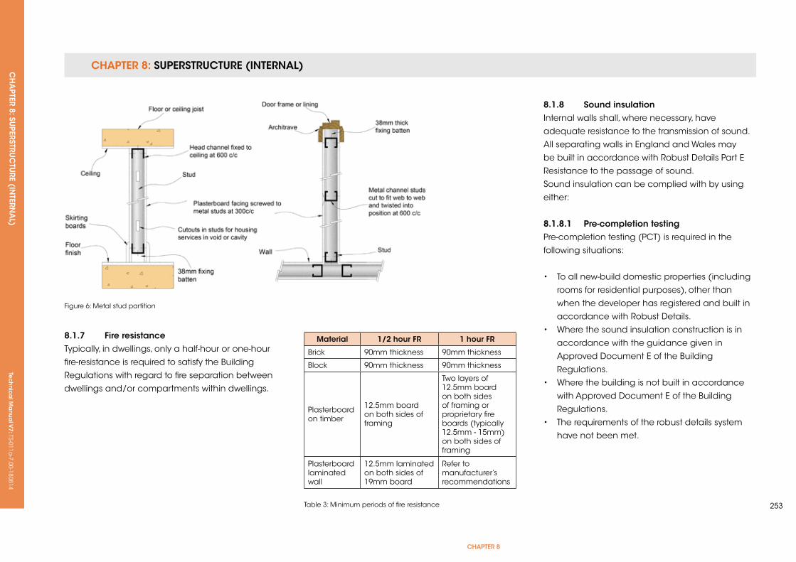
CHAPTER 8: SUPERSTRUCTURE (INTERNAL) CH
APTER 8: SU
PERSTRUC
TURE (IN
TERNA
L) Te
ch
nic
al M
anu
al V
7: TS-011a-7.00-180814
CHAPTER 8
253
8.1.7 fire resistanceTypically, in dwellings, only a half-hour or one-hour
fire-resistance is required to satisfy the Building
Regulations with regard to fire separation between
dwellings and/or compartments within dwellings.
Figure 6: Metal stud partition
8.1.8 sound insulationInternal walls shall, where necessary, have
adequate resistance to the transmission of sound.
All separating walls in England and Wales may
be built in accordance with Robust Details Part E
Resistance to the passage of sound.
Sound insulation can be complied with by using
either:
8.1.8.1 Pre-completion testing Pre-completion testing (PCT) is required in the
following situations:
• To all new-build domestic properties (including
rooms for residential purposes), other than
when the developer has registered and built in
accordance with Robust Details.
• Where the sound insulation construction is in
accordance with the guidance given in
Approved Document E of the Building
Regulations.
• Where the building is not built in accordance
with Approved Document E of the Building
Regulations.
• The requirements of the robust details system
have not been met.
Material 1/2 hour fr 1 hour fr
Brick 90mm thickness 90mm thickness
Block 90mm thickness 90mm thickness
Plasterboard on timber
12.5mm board on both sides of framing
Two layers of 12.5mm board on both sides of framing or proprietary fire boards (typically 12.5mm - 15mm) on both sides of framing
Plasterboard laminated wall
12.5mm laminated on both sides of 19mm board
Refer to manufacturer’s recommendations
Table 3: Minimum periods of fire resistance
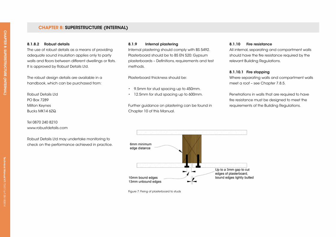
CHAPTER 8: SUPERSTRUCTURE (INTERNAL) CH
APTER 8: SU
PERSTRUC
TURE (IN
TERNA
L) Te
ch
nic
al M
anu
al V
7: TS-011a-7.00-180814
8.1.8.2 robust details The use of robust details as a means of providing
adequate sound insulation applies only to party
walls and floors between different dwellings or flats.
It is approved by Robust Details Ltd.
The robust design details are available in a
handbook, which can be purchased from:
Robust Details Ltd
PO Box 7289
Milton keynes
Bucks Mk14 6Zq
Tel 0870 240 8210
www.robustdetails.com
Robust Details Ltd may undertake monitoring to
check on the performance achieved in practice.
Figure 7: Fixing of plasterboard to studs
8.1.9 internal plasteringInternal plastering should comply with BS 5492.
Plasterboard should be to BS EN 520: Gypsum
plasterboards – Definitions, requirements and test
methods.
Plasterboard thickness should be:
• 9.5mm for stud spacing up to 450mm.
• 12.5mm for stud spacing up to 600mm.
Further guidance on plastering can be found in
Chapter 10 of this Manual.
8.1.10 fire resistanceAll internal, separating and compartment walls
should have the fire resistance required by the
relevant Building Regulations.
8.1.10.1 fire stoppingWhere separating walls and compartment walls
meet a roof – see Chapter 7.8.5.
Penetrations in walls that are required to have
fire resistance must be designed to meet the
requirements of the Building Regulations.
Tec
hn
ica
l Ma
nua
l V6: TS-011a
-6.00-010413Te
ch
nic
al M
anu
al V
7: TS-011a-7.00-180814
FUNCTIONAL REQUIREMENTS
255
CHAPTer 8
8.2 uPPer fLoors
Workmanshipi. All workmanship must be within the tolerances defined in Chapter 1
of this Manual.
ii. All work is to be carried out by a technically competent person in
a workmanlike manner.
Materialsi. All materials should be stored correctly in a manner that will not cause
damage or deterioration of the product.
ii. All materials, products and building systems shall be appropriate and
suitable for their intended purpose.
iii. The structure shall, unless specifically agreed otherwise with the
Warranty provider, have a life of not less than 60 years. Individual
components and assemblies, not integral to the structure, may have
a lesser durability, but not in any circumstances less than 15 years.
Designi. The design and specifications shall provide a clear indication of the
design intent and demonstrate a satisfactory level of performance.
ii. Party floors between dwellings must achieve satisfactory levels of
sound insulation to meet the relevant requirements of the Building
Regulations.
iii. Structural elements outside the parameters of regional Approved
Documents must be supported by structural calculations provided by
a suitably qualified expert.
iv. The materials, design and construction must meet the relevant
Building Regulations, British Standards, Eurocodes and other statutory
requirements.
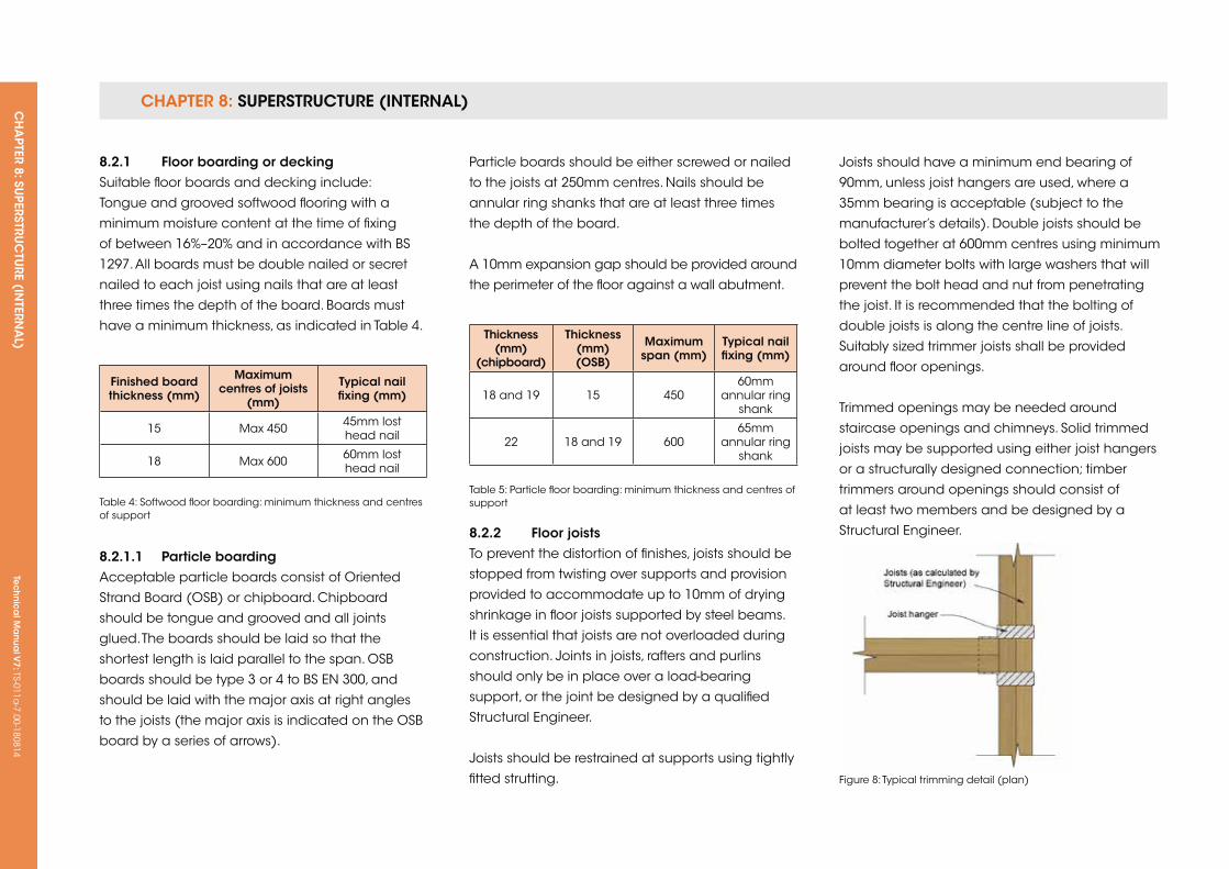
CHAPTER 8: SUPERSTRUCTURE (INTERNAL) CH
APTER 8: SU
PERSTRUC
TURE (IN
TERNA
L) Te
ch
nic
al M
anu
al V
7: TS-011a-7.00-180814
finished board thickness (mm)
Maximum centres of joists
(mm)
Typical nail fixing (mm)
15 Max 450 45mm lost head nail
18 Max 600 60mm lost head nail
Table 4: Softwood floor boarding: minimum thickness and centres of support
Thickness (mm)
(chipboard)
Thickness (mm) (osB)
Maximum span (mm)
Typical nail fixing (mm)
18 and 19 15 45060mm
annular ring shank
22 18 and 19 60065mm
annular ring shank
Table 5: Particle floor boarding: minimum thickness and centres of support
Figure 8: Typical trimming detail (plan)
8.2.1 floor boarding or deckingSuitable floor boards and decking include:
Tongue and grooved softwood flooring with a
minimum moisture content at the time of fixing
of between 16%–20% and in accordance with BS
1297. All boards must be double nailed or secret
nailed to each joist using nails that are at least
three times the depth of the board. Boards must
have a minimum thickness, as indicated in Table 4.
8.2.1.1 Particle boardingAcceptable particle boards consist of Oriented
Strand Board (OSB) or chipboard. Chipboard
should be tongue and grooved and all joints
glued. The boards should be laid so that the
shortest length is laid parallel to the span. OSB
boards should be type 3 or 4 to BS EN 300, and
should be laid with the major axis at right angles
to the joists (the major axis is indicated on the OSB
board by a series of arrows).
Particle boards should be either screwed or nailed
to the joists at 250mm centres. Nails should be
annular ring shanks that are at least three times
the depth of the board.
A 10mm expansion gap should be provided around
the perimeter of the floor against a wall abutment.
8.2.2 floor joistsTo prevent the distortion of finishes, joists should be
stopped from twisting over supports and provision
provided to accommodate up to 10mm of drying
shrinkage in floor joists supported by steel beams.
It is essential that joists are not overloaded during
construction. Joints in joists, rafters and purlins
should only be in place over a load-bearing
support, or the joint be designed by a qualified
Structural Engineer.
Joists should be restrained at supports using tightly
fitted strutting.
Joists should have a minimum end bearing of
90mm, unless joist hangers are used, where a
35mm bearing is acceptable (subject to the
manufacturer’s details). Double joists should be
bolted together at 600mm centres using minimum
10mm diameter bolts with large washers that will
prevent the bolt head and nut from penetrating
the joist. It is recommended that the bolting of
double joists is along the centre line of joists.
Suitably sized trimmer joists shall be provided
around floor openings.
Trimmed openings may be needed around
staircase openings and chimneys. Solid trimmed
joists may be supported using either joist hangers
or a structurally designed connection; timber
trimmers around openings should consist of
at least two members and be designed by a
Structural Engineer.
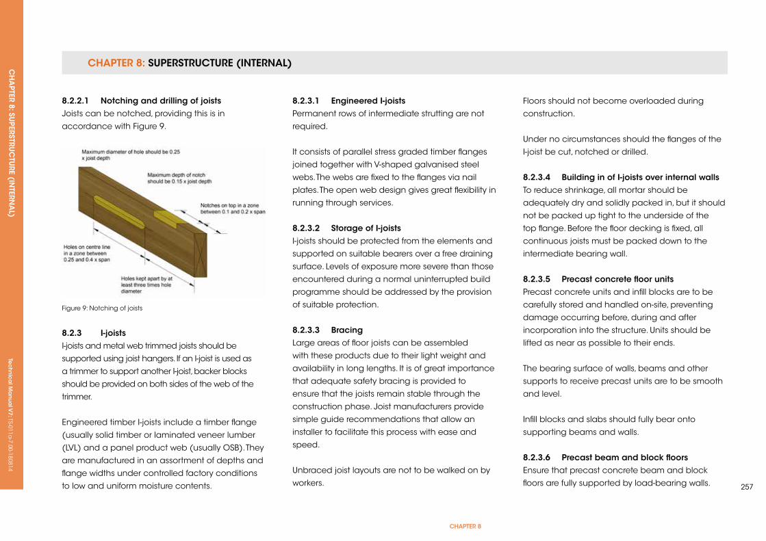
CHAPTER 8: SUPERSTRUCTURE (INTERNAL) CH
APTER 8: SU
PERSTRUC
TURE (IN
TERNA
L) Te
ch
nic
al M
anu
al V
7: TS-011a-7.00-180814
CHAPTER 8
257
Figure 9: Notching of joists
8.2.2.1 notching and drilling of joistsJoists can be notched, providing this is in
accordance with Figure 9.
8.2.3 i-joistsI-joists and metal web trimmed joists should be
supported using joist hangers. If an I-joist is used as
a trimmer to support another I-joist, backer blocks
should be provided on both sides of the web of the
trimmer.
Engineered timber I-joists include a timber flange
(usually solid timber or laminated veneer lumber
(LVL) and a panel product web (usually OSB). They
are manufactured in an assortment of depths and
flange widths under controlled factory conditions
to low and uniform moisture contents.
8.2.3.1 engineered i-joistsPermanent rows of intermediate strutting are not
required.
It consists of parallel stress graded timber flanges
joined together with V-shaped galvanised steel
webs. The webs are fixed to the flanges via nail
plates. The open web design gives great flexibility in
running through services.
8.2.3.2 storage of i-joistsI-joists should be protected from the elements and
supported on suitable bearers over a free draining
surface. Levels of exposure more severe than those
encountered during a normal uninterrupted build
programme should be addressed by the provision
of suitable protection.
8.2.3.3 BracingLarge areas of floor joists can be assembled
with these products due to their light weight and
availability in long lengths. It is of great importance
that adequate safety bracing is provided to
ensure that the joists remain stable through the
construction phase. Joist manufacturers provide
simple guide recommendations that allow an
installer to facilitate this process with ease and
speed.
unbraced joist layouts are not to be walked on by
workers.
Floors should not become overloaded during
construction.
under no circumstances should the flanges of the
I-joist be cut, notched or drilled.
8.2.3.4 Building in of i-joists over internal walls To reduce shrinkage, all mortar should be
adequately dry and solidly packed in, but it should
not be packed up tight to the underside of the
top flange. Before the floor decking is fixed, all
continuous joists must be packed down to the
intermediate bearing wall.
8.2.3.5 Precast concrete floor unitsPrecast concrete units and infill blocks are to be
carefully stored and handled on-site, preventing
damage occurring before, during and after
incorporation into the structure. units should be
lifted as near as possible to their ends.
The bearing surface of walls, beams and other
supports to receive precast units are to be smooth
and level.
Infill blocks and slabs should fully bear onto
supporting beams and walls.
8.2.3.6 Precast beam and block floorsEnsure that precast concrete beam and block
floors are fully supported by load-bearing walls.
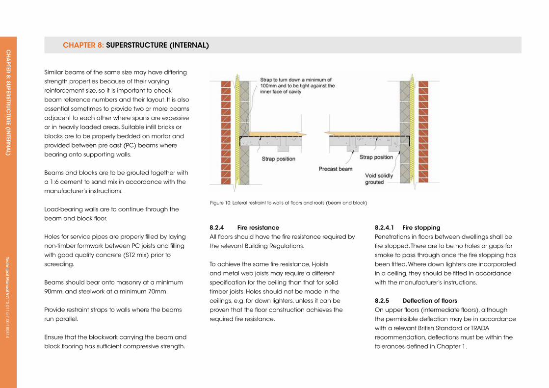
CHAPTER 8: SUPERSTRUCTURE (INTERNAL) CH
APTER 8: SU
PERSTRUC
TURE (IN
TERNA
L) Te
ch
nic
al M
anu
al V
7: TS-011a-7.00-180814
Figure 10: Lateral restraint to walls at floors and roofs (beam and block)
Similar beams of the same size may have differing
strength properties because of their varying
reinforcement size, so it is important to check
beam reference numbers and their layout. It is also
essential sometimes to provide two or more beams
adjacent to each other where spans are excessive
or in heavily loaded areas. Suitable infill bricks or
blocks are to be properly bedded on mortar and
provided between pre cast (PC) beams where
bearing onto supporting walls.
Beams and blocks are to be grouted together with
a 1:6 cement to sand mix in accordance with the
manufacturer’s instructions.
Load-bearing walls are to continue through the
beam and block floor.
Holes for service pipes are properly filled by laying
non-timber formwork between PC joists and filling
with good quality concrete (ST2 mix) prior to
screeding.
Beams should bear onto masonry at a minimum
90mm, and steelwork at a minimum 70mm.
Provide restraint straps to walls where the beams
run parallel.
Ensure that the blockwork carrying the beam and
block flooring has sufficient compressive strength.
8.2.4 fire resistanceAll floors should have the fire resistance required by
the relevant Building Regulations.
To achieve the same fire resistance, I-joists
and metal web joists may require a different
specification for the ceiling than that for solid
timber joists. Holes should not be made in the
ceilings, e.g. for down lighters, unless it can be
proven that the floor construction achieves the
required fire resistance.
8.2.4.1 fire stoppingPenetrations in floors between dwellings shall be
fire stopped. There are to be no holes or gaps for
smoke to pass through once the fire stopping has
been fitted. Where down lighters are incorporated
in a ceiling, they should be fitted in accordance
with the manufacturer’s instructions.
8.2.5 Deflection of floorsOn upper floors (intermediate floors), although
the permissible deflection may be in accordance
with a relevant British Standard or TRADA
recommendation, deflections must be within the
tolerances defined in Chapter 1.
Tec
hn
ica
l Ma
nua
l V6: TS-011a
-6.00-010413Te
ch
nic
al M
anu
al V
7: TS-011a-7.00-180814
FUNCTIONAL REQUIREMENTS
259
CHAPTer 8
8.3 sTAirs
Workmanshipi. All workmanship must be within the tolerances defined in Chapter 1
of this Manual.
ii. All work is to be carried out by a technically competent person in
a workmanlike manner.
Materialsi. All materials should be stored correctly in a manner that will not cause
damage or deterioration of the product.
ii. All materials, products and building systems shall be appropriate and
suitable for their intended purpose.
iii. The structure shall, unless specifically agreed otherwise with the
Warranty provider, have a life of not less than 60 years. Individual
components and assemblies, not integral to the structure, may have a
lesser durability, but not in any circumstances less than 15 years.
Designi. The design and specifications shall provide a clear indication of the
design intent and demonstrate a satisfactory level of performance.
ii. Stairs and landings must have appropriate guarding to meet the
relevant Building Regulations
iii. Structural elements outside the parameters of regional Approved
Documents must be supported by structural calculations provided by
a suitably qualified expert.
iv. The material, design and construction must meet the relevant
Building Regulations, British Standards, Eurocodes and other statutory
requirements.
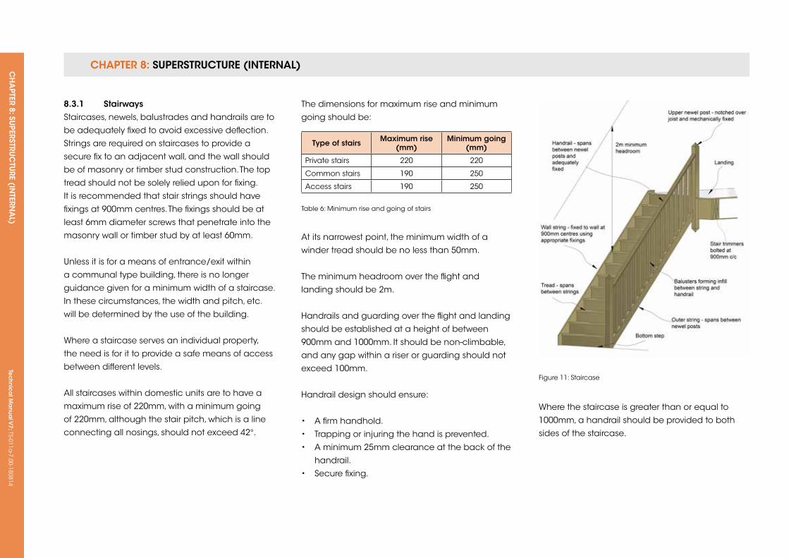
CHAPTER 8: SUPERSTRUCTURE (INTERNAL) CH
APTER 8: SU
PERSTRUC
TURE (IN
TERNA
L) Te
ch
nic
al M
anu
al V
7: TS-011a-7.00-180814
Type of stairs Maximum rise (mm)
Minimum going (mm)
Private stairs 220 220
Common stairs 190 250
Access stairs 190 250
Table 6: Minimum rise and going of stairs
Figure 11: Staircase
8.3.1 stairwaysStaircases, newels, balustrades and handrails are to
be adequately fixed to avoid excessive deflection.
Strings are required on staircases to provide a
secure fix to an adjacent wall, and the wall should
be of masonry or timber stud construction. The top
tread should not be solely relied upon for fixing.
It is recommended that stair strings should have
fixings at 900mm centres. The fixings should be at
least 6mm diameter screws that penetrate into the
masonry wall or timber stud by at least 60mm.
unless it is for a means of entrance/exit within
a communal type building, there is no longer
guidance given for a minimum width of a staircase.
In these circumstances, the width and pitch, etc.
will be determined by the use of the building.
Where a staircase serves an individual property,
the need is for it to provide a safe means of access
between different levels.
All staircases within domestic units are to have a
maximum rise of 220mm, with a minimum going
of 220mm, although the stair pitch, which is a line
connecting all nosings, should not exceed 42°.
The dimensions for maximum rise and minimum
going should be:
At its narrowest point, the minimum width of a
winder tread should be no less than 50mm.
The minimum headroom over the flight and
landing should be 2m.
Handrails and guarding over the flight and landing
should be established at a height of between
900mm and 1000mm. It should be non-climbable,
and any gap within a riser or guarding should not
exceed 100mm.
Handrail design should ensure:
• A firm handhold.
• Trapping or injuring the hand is prevented.
• A minimum 25mm clearance at the back of the
handrail.
• Secure fixing.
Where the staircase is greater than or equal to
1000mm, a handrail should be provided to both
sides of the staircase.
CHAPTER 8: SUPERSTRUCTURE (INTERNAL) CH
APTER 8: SU
PERSTRUC
TURE (IN
TERNA
L) Te
ch
nic
al M
anu
al V
7: TS-011a-7.00-180814
CHAPTER 8
261
8.3.2 Location and fixing
8.3.2.1 HeadroomThe overall floor opening is to be checked for the
size required to accept the stairs and allow for
sufficient headroom.
The minimum headroom above the stairs is to be
measured vertically from the pitch line. The clear
headroom should be 2m over the entire length
and width of a stairway, including landings.
8.3.2.2 overall vertical riseStaircases are traditionally manufactured off-site,
so the floor-to-floor dimensions should be extremely
accurate, although an allowance should be made
for floor finishes to structural floors or staircase
treads.
8.3.2.3 PitchStaircases should be accurately located and fixed
with the string at the correct angle, so that all
treads are horizontal.
8.3.2.4 LandingsLandings are to be properly framed to provide full
support to, and secure fixings for, flights, nosings,
newels, apron linings, etc.
8.3.2.5 floor finishesAllowance should be made for stair and floor
finishes, ensuring that all risers are equal.
8.3.2.6 PitchThe maximum angle of pitch of a stairway should
not exceed:
• 42° for private stairs
• 38° for common or access stairs
8.3.2.7 LightingArtificial light sources should be provided to all
staircases and landings. Within a dwelling, lighting
to stairs should be controlled by two-way switching.
Automatic light-sensitive controls may be used in
common areas, provided lights can also be two-
way switched manually.
Where staircases are lit by glazing, any glass
immediately adjacent to the stair should be:
• protected by a balustrade or railing, or
• toughened or laminated glass, or
• constructed of glass blocks
Tec
hn
ica
l Ma
nua
l V6: TS-011a
-6.00-010413Te
ch
nic
al M
anu
al V
7: TS-011a-7.00-180814
FUNCTIONAL REQUIREMENTS
8.4 fire sToPPing AnD fire ProTeCTion To fLATs AnD APArTMenTs
Workmanshipi. All workmanship must be within the tolerances defined in Chapter 1
of this Manual.
ii. All work is to be carried out by a technically competent person in
a workmanlike manner.
iii. Fire stopping is to be completed by a third-party approved contractor.
Materialsi. All materials should be stored correctly in a manner that will not cause
damage or deterioration of the product.
ii. All materials, products and building systems shall be appropriate and
suitable for their intended purpose.
iii. The structure shall, unless specifically agreed otherwise with the
Warranty provider, have a life of not less than 60 years. Individual
components and assemblies, not integral to the structure, may have a
lesser durability, but not in any circumstances less than 15 years.
iv. Fire stopping and fire protection materials are to have relevant third-
party certification confirming suitability in its application.
Designi. The design and specifications shall provide a clear indication of the
design intent and demonstrate a satisfactory level of performance.
ii. Structural elements outside the parameters of regional Approved
Documents must be supported by structural calculations provided by
a suitably qualified expert.
iii. The materials, design and construction must meet the relevant
Building Regulations, British Standards, Eurocodes and other statutory
requirements.
iv. Layouts indicating the positions of compartment walls/floors and
other lines of fire resistance must be available to the Builder and Risk
Management Surveyor.
Limitation of this sectionChapter 8.4 applies to any building that contains flats or apartments with
a floor four or more storeys above the ground.
CHAPTER 8: SUPERSTRUCTURE (INTERNAL) CH
APTER 8: SU
PERSTRUC
TURE (IN
TERNA
L) Te
ch
nic
al M
anu
al V
7: TS-011a-7.00-180814
CHAPTER 8
263
8.4.1 introductionAlthough building legislation is robust in applying
provisions for fire protection and fire stopping, it can
often be difficult to implement high standards of
fire stopping in complex buildings. This can lead to
significant safety risks if the building does not have
the correct levels of fire protection and if holes
in compartment walls are not sealed correctly.
This section assists Developers in providing good
standards of fire stopping and fire protection.
It is not the intention to enhance the requirements
of the Building Regulations in this section, but
more to ensure that the statutory requirements
are applied correctly to the construction. It is
therefore deemed that the requirements of Part B
of the Building Regulations in England and Wales,
or Section 2 of the Scottish Building Standards
(whichever is appropriate depending on region),
that apply to fire stopping, separating walls, service
penetrations, minimum periods of fire resistance
and concealed spaces will also meet the
requirements of this Technical Manual.
This section applies to buildings with four or more
storeys that contain flats or apartments; however, it
is recommended that the guidance is followed for
buildings constructed using Modern Methods of
Construction and Innovative Materials.
8.4.2 fire stopping
Design informationDrawings showing the lines of compartmentation
and the lines of fire-resisting construction should
be provided to the Surveyor and the Builder. The
drawings should also give the required level of fire
resistance for each element. Drawings to show the
position of cavity barriers should be provided, and
the specification of cavity barriers included.
Materials for fire stopping and cavity barriersAll materials used to form a fire barrier must have
relevant third-party certification in accordance
with section 3 of this Manual, or be CE marked
in accordance with the Construction Products
Regulations. The materials must be installed in
accordance with the manufacturer’s instructions
and recommendations.
installationThe fire stopping material or cavity barriers
should be installed by a person who is deemed
competent to install such products. A competent
person is deemed to be a third-party approved
contractor specialising in fire stopping and passive
fire protection.
8.4.3 fire protection in buildings
Design informationThe design details must show the correct level of
fire resistance for the building, in accordance with
the Part B of the Building Regulations or Section 2
of the Scottish Building Standards, depending on
region.
Materials for fire protectionAll materials used to form a fire barrier must have
relevant third-party certification in accordance
with Chapter 2 of this Manual, or be CE marked
in accordance with the Construction Products
Regulations. The materials must be installed in
accordance with the manufacturer’s instructions
and recommendations.
installationThe fire stopping material or cavity barriers
should be installed by a person who is deemed
competent to install such products.
Where intumescent paints are used to provide
the required level of fire protection, certification
confirming that the paint applied will achieve the
correct level of fire protection is required.

Tec
hn
ica
l Ma
nua
l V6: TS-011a
-6.00-010413Te
ch
nic
al M
anu
al V
7: TS-011a-7.00-180814
CH
APTER 9: BU
ILDIN
G SERV
ICES
Tec
hn
ica
l Ma
nua
l V7: TS-011a
-7.00-180814
CHAPTER 9
265
CHAPTer 9: BuiLDing serviCes
ConTenTs
9.1 DRAINAGE (BELOW GROuND)
9.2 DRAINAGE (ABOVE GROuND)
9.3 ELECTRICAL INSTALLATIONS
9.4 HEATING AND MECHANICAL SERVICES

Tec
hn
ica
l Ma
nua
l V6: TS-011a
-6.00-010413Te
ch
nic
al M
anu
al V
7: TS-011a-7.00-180814
FUNCTIONAL REQUIREMENTS
9.1 DrAinAge (BeLoW grounD)
Workmanshipi. All workmanship must be within the tolerances defined in Chapter 1
of this Manual.
ii. All work is to be carried out by a technically competent person in
a workmanlike manner.
Materialsi. All materials should be stored correctly in a manner that will not cause
damage or deterioration of the product.
ii. All materials, products and building systems shall be appropriate and
suitable for their intended purpose.
iii. The structure shall, unless specifically agreed otherwise with the
Warranty provider, have a life of not less than 60 years. Individual
components and assemblies, not integral to the structure, may have a
lesser durability, but not in any circumstances less than 15 years.
Designi. The design and specifications shall provide a clear indication of the
design intent and demonstrate a satisfactory level of performance.
ii. The materials, design and construction must meet the relevant
Building Regulations, British Standards, Eurocodes and other statutory
requirements.
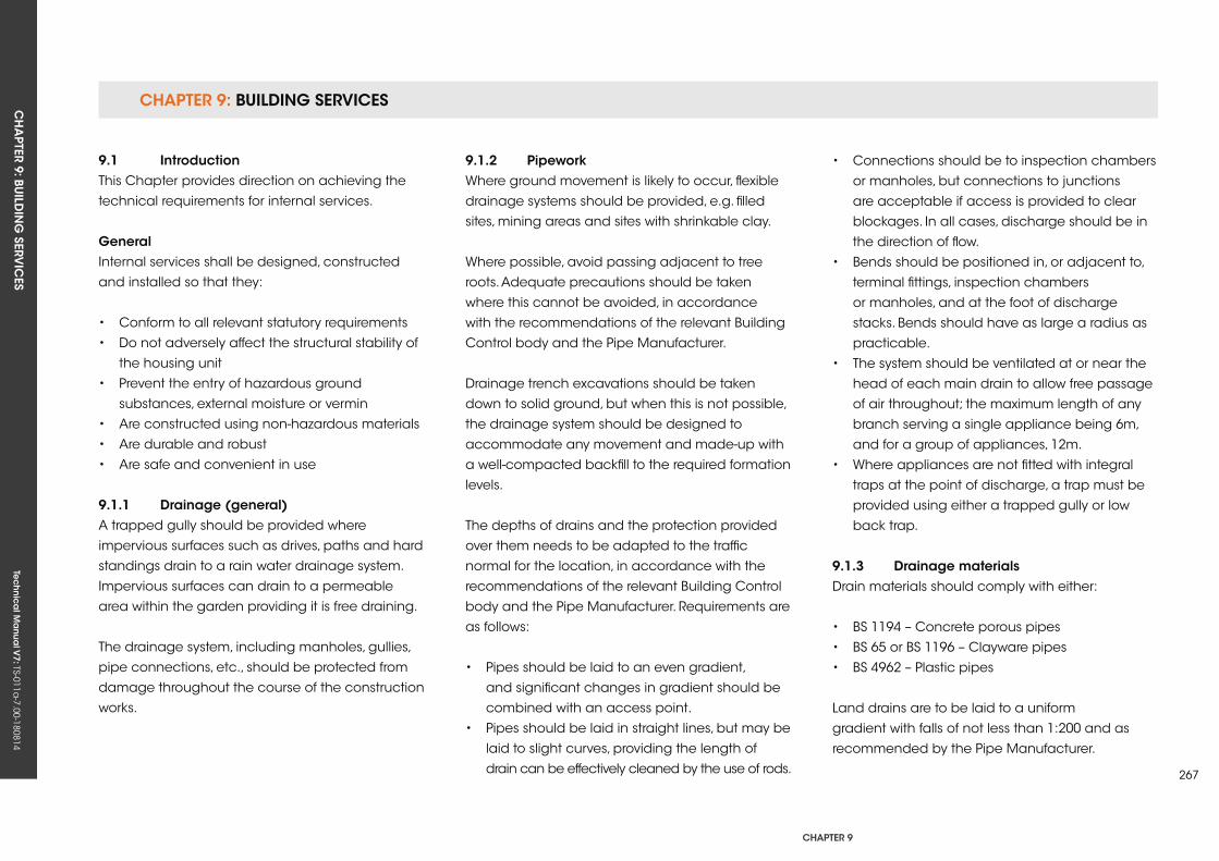
CHAPTER 9: BUILDING SERVICESCH
APTER 9: BU
ILDIN
G SERV
ICES
Tec
hn
ica
l Ma
nua
l V7: TS-011a
-7.00-180814
CHAPTER 9
267
9.1 introductionThis Chapter provides direction on achieving the
technical requirements for internal services.
generalInternal services shall be designed, constructed
and installed so that they:
• Conform to all relevant statutory requirements
• Do not adversely affect the structural stability of
the housing unit
• Prevent the entry of hazardous ground
substances, external moisture or vermin
• Are constructed using non-hazardous materials
• Are durable and robust
• Are safe and convenient in use
9.1.1 Drainage (general)A trapped gully should be provided where
impervious surfaces such as drives, paths and hard
standings drain to a rain water drainage system.
Impervious surfaces can drain to a permeable
area within the garden providing it is free draining.
The drainage system, including manholes, gullies,
pipe connections, etc., should be protected from
damage throughout the course of the construction
works.
9.1.2 PipeworkWhere ground movement is likely to occur, flexible
drainage systems should be provided, e.g. filled
sites, mining areas and sites with shrinkable clay.
Where possible, avoid passing adjacent to tree
roots. Adequate precautions should be taken
where this cannot be avoided, in accordance
with the recommendations of the relevant Building
Control body and the Pipe Manufacturer.
Drainage trench excavations should be taken
down to solid ground, but when this is not possible,
the drainage system should be designed to
accommodate any movement and made-up with
a well-compacted backfill to the required formation
levels.
The depths of drains and the protection provided
over them needs to be adapted to the traffic
normal for the location, in accordance with the
recommendations of the relevant Building Control
body and the Pipe Manufacturer. Requirements are
as follows:
• Pipes should be laid to an even gradient,
and significant changes in gradient should be
combined with an access point.
• Pipes should be laid in straight lines, but may be
laid to slight curves, providing the length of
drain can be effectively cleaned by the use of rods.
• Connections should be to inspection chambers
or manholes, but connections to junctions
are acceptable if access is provided to clear
blockages. In all cases, discharge should be in
the direction of flow.
• Bends should be positioned in, or adjacent to,
terminal fittings, inspection chambers
or manholes, and at the foot of discharge
stacks. Bends should have as large a radius as
practicable.
• The system should be ventilated at or near the
head of each main drain to allow free passage
of air throughout; the maximum length of any
branch serving a single appliance being 6m,
and for a group of appliances, 12m.
• Where appliances are not fitted with integral
traps at the point of discharge, a trap must be
provided using either a trapped gully or low
back trap.
9.1.3 Drainage materials Drain materials should comply with either:
• BS 1194 – Concrete porous pipes
• BS 65 or BS 1196 – Clayware pipes
• BS 4962 – Plastic pipes
Land drains are to be laid to a uniform
gradient with falls of not less than 1:200 and as
recommended by the Pipe Manufacturer.
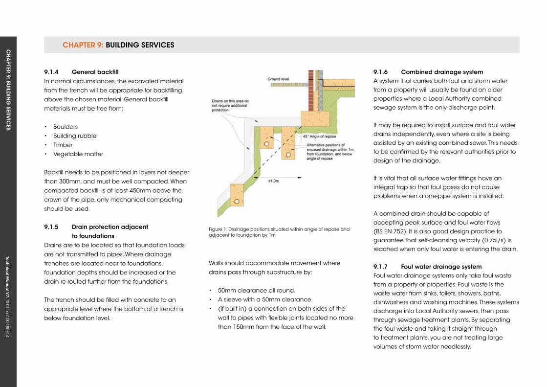
CHAPTER 9: BUILDING SERVICESCH
APTER 9: BU
ILDIN
G SERV
ICES
Tec
hn
ica
l Ma
nua
l V7: TS-011a
-7.00-180814
9.1.4 general backfillIn normal circumstances, the excavated material
from the trench will be appropriate for backfilling
above the chosen material. General backfill
materials must be free from:
• Boulders
• Building rubble
• Timber
• Vegetable matter
Backfill needs to be positioned in layers not deeper
than 300mm, and must be well compacted. When
compacted backfill is at least 450mm above the
crown of the pipe, only mechanical compacting
should be used.
9.1.5 Drain protection adjacent to foundationsDrains are to be located so that foundation loads
are not transmitted to pipes. Where drainage
trenches are located near to foundations,
foundation depths should be increased or the
drain re-routed further from the foundations.
The trench should be filled with concrete to an
appropriate level where the bottom of a trench is
below foundation level.
Walls should accommodate movement where
drains pass through substructure by:
• 50mm clearance all round.
• A sleeve with a 50mm clearance.
• (If built in) a connection on both sides of the
wall to pipes with flexible joints located no more
than 150mm from the face of the wall.
Figure 1: Drainage positions situated within angle of repose and adjacent to foundation by 1m
9.1.6 Combined drainage systemA system that carries both foul and storm water from a property will usually be found on older properties where a Local Authority combined sewage system is the only discharge point.
It may be required to install surface and foul water drains independently, even where a site is being assisted by an existing combined sewer. This needs to be confirmed by the relevant authorities prior to design of the drainage.
It is vital that all surface water fittings have an integral trap so that foul gases do not cause problems when a one-pipe system is installed.
A combined drain should be capable of accepting peak surface and foul water flows (BS EN 752). It is also good design practice to guarantee that self-cleansing velocity (0.75l/s) is reached when only foul water is entering the drain.
9.1.7 foul water drainage systemFoul water drainage systems only take foul waste from a property or properties. Foul waste is the waste water from sinks, toilets, showers, baths, dishwashers and washing machines. These systems discharge into Local Authority sewers, then pass through sewage treatment plants. By separating the foul waste and taking it straight through to treatment plants, you are not treating large
volumes of storm water needlessly.
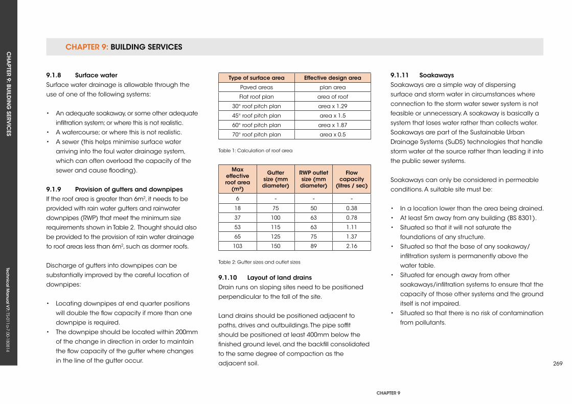
CHAPTER 9: BUILDING SERVICESCH
APTER 9: BU
ILDIN
G SERV
ICES
Tec
hn
ica
l Ma
nua
l V7: TS-011a
-7.00-180814
CHAPTER 9
269
9.1.8 surface waterSurface water drainage is allowable through the
use of one of the following systems:
• An adequate soakaway, or some other adequate
infiltration system; or where this is not realistic.
• A watercourse; or where this is not realistic.
• A sewer (this helps minimise surface water
arriving into the foul water drainage system,
which can often overload the capacity of the
sewer and cause flooding).
9.1.9 Provision of gutters and downpipesIf the roof area is greater than 6m2, it needs to be
provided with rain water gutters and rainwater
downpipes (RWP) that meet the minimum size
requirements shown in Table 2. Thought should also
be provided to the provision of rain water drainage
to roof areas less than 6m2, such as dormer roofs.
Discharge of gutters into downpipes can be
substantially improved by the careful location of
downpipes:
• Locating downpipes at end quarter positions
will double the flow capacity if more than one
downpipe is required.
• The downpipe should be located within 200mm
of the change in direction in order to maintain
the flow capacity of the gutter where changes
in the line of the gutter occur.
9.1.10 Layout of land drainsDrain runs on sloping sites need to be positioned
perpendicular to the fall of the site.
Land drains should be positioned adjacent to
paths, drives and outbuildings. The pipe soffit
should be positioned at least 400mm below the
finished ground level, and the backfill consolidated
to the same degree of compaction as the
adjacent soil.
Type of surface area effective design area
Paved areas plan area
Flat roof plan area of roof
30° roof pitch plan area x 1.29
45° roof pitch plan area x 1.5
60° roof pitch plan area x 1.87
70° roof pitch plan area x 0.5
Table 1: Calculation of roof area
Max effective roof area
(m²)
gutter size (mm diameter)
rWP outlet size (mm diameter)
flow capacity
(litres / sec)
6 - - -18 75 50 0.38
37 100 63 0.78
53 115 63 1.11
65 125 75 1.37
103 150 89 2.16
Table 2: Gutter sizes and outlet sizes
9.1.11 soakawaysSoakaways are a simple way of dispersing
surface and storm water in circumstances where
connection to the storm water sewer system is not
feasible or unnecessary. A soakaway is basically a
system that loses water rather than collects water.
Soakaways are part of the Sustainable urban
Drainage Systems (SuDS) technologies that handle
storm water at the source rather than leading it into
the public sewer systems.
Soakaways can only be considered in permeable
conditions. A suitable site must be:
• In a location lower than the area being drained.
• At least 5m away from any building (BS 8301).
• Situated so that it will not saturate the
foundations of any structure.
• Situated so that the base of any soakaway/
infiltration system is permanently above the
water table.
• Situated far enough away from other
soakaways/infiltration systems to ensure that the
capacity of those other systems and the ground
itself is not impaired.
• Situated so that there is no risk of contamination
from pollutants.
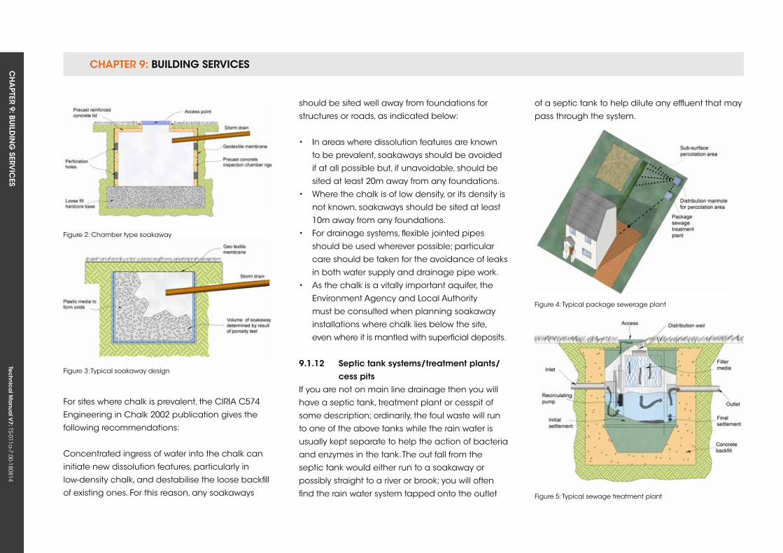
CHAPTER 9: BUILDING SERVICESCH
APTER 9: BU
ILDIN
G SERV
ICES
Tec
hn
ica
l Ma
nua
l V7: TS-011a
-7.00-180814
For sites where chalk is prevalent, the CIRIA C574
Engineering in Chalk 2002 publication gives the
following recommendations:
Concentrated ingress of water into the chalk can
initiate new dissolution features, particularly in
low-density chalk, and destabilise the loose backfill
of existing ones. For this reason, any soakaways
Figure 2: Chamber type soakaway
Figure 3: Typical soakaway design
Figure 4: Typical package sewerage plant
Figure 5: Typical sewage treatment plant
should be sited well away from foundations for
structures or roads, as indicated below:
• In areas where dissolution features are known
to be prevalent, soakaways should be avoided
if at all possible but, if unavoidable, should be
sited at least 20m away from any foundations.
• Where the chalk is of low density, or its density is
not known, soakaways should be sited at least
10m away from any foundations.
• For drainage systems, flexible jointed pipes
should be used wherever possible; particular
care should be taken for the avoidance of leaks
in both water supply and drainage pipe work.
• As the chalk is a vitally important aquifer, the
Environment Agency and Local Authority
must be consulted when planning soakaway
installations where chalk lies below the site,
even where it is mantled with superficial deposits.
9.1.12 septic tank systems/treatment plants/ cess pitsIf you are not on main line drainage then you will
have a septic tank, treatment plant or cesspit of
some description; ordinarily, the foul waste will run
to one of the above tanks while the rain water is
usually kept separate to help the action of bacteria
and enzymes in the tank. The out fall from the
septic tank would either run to a soakaway or
possibly straight to a river or brook; you will often
find the rain water system tapped onto the outlet
of a septic tank to help dilute any effluent that may
pass through the system.
Tec
hn
ica
l Ma
nua
l V6: TS-011a
-6.00-010413Te
ch
nic
al M
anu
al V
7: TS-011a-7.00-180814
FUNCTIONAL REQUIREMENTS
271
CHAPTer 9
9.2 DrAinAge (ABove grounD)
Workmanshipi. All workmanship must be within the tolerances defined in Chapter 1
of this Manual.
ii. All work is to be carried out by a technically competent person in
a workmanlike manner.
Materialsi. All materials should be stored correctly in a manner that will not cause
damage or deterioration of the product.
ii. All materials, products and building systems shall be appropriate and
suitable for their intended purpose.
iii. The structure shall, unless specifically agreed otherwise with the
Warranty provider, have a life of not less than 60 years. Individual
components and assemblies, not integral to the structure, may have
a lesser durability, but not in any circumstances less than 15 years.
Designi. The design and specifications shall provide a clear indication of the
design intent and demonstrate a satisfactory level of performance.
ii. The materials, design and construction must meet the relevant
Building Regulations, British Standards, Eurocodes and other statutory
requirements.
CHAPTER 9: BUILDING SERVICESCH
APTER 9: BU
ILDIN
G SERV
ICES
Tec
hn
ica
l Ma
nua
l V7: TS-011a
-7.00-180814
9.2.1 Above ground drainageAll above ground plumbing systems need to be
designed to allow the unobstructed flow of waste
water from an appliance to the underground
drainage system. To achieve this, the points below
should be noted at the design and installation
stages:
• Provide rodding access facilities at all changes
of direction.
• Avoid bends and changes of direction in the
wet part of the above ground drainage system.
• 75mm-deep seal traps should always be used,
except on a WC or where an appliance on the
ground floor discharges directly into a trapped
gully.
• Pipe sizes should not exceed the dimensions for
diameter against pipe length.
• Pipes should be laid at gradient 1:80 or better.
• Any admittance valve fitted to the system
should be located above the highest flood level
of any appliance connected to that stack pipe.
• Enclosures to air admittance valves should be
adequately ventilated.
• The highest point of a drainage system (head
of run) should always be vented to the external
air.
9.2.2 soil and waste systemsIn all above ground plumbing systems, the
unobstructed flow of waste from an appliance to
the underground drainage will be allowed. This will
be achieved by following the notes below at the
design and installation stages:
• Rodding access is to be provided at all
direction changes.
• Pipe and gutter sizes are adequate to take the
expected rate of discharge, and are laid at
suitable gradients with the minimum of direction
changes.
• 75mm deep seal traps should always be used,
except on a WC where a 50mm depth of water
seal can be used on the above ground
drainage system.
• Pipe sizes should not exceed the dimensions for
diameter against pipe length.
• Pipes should be laid at a gradient of 1:80 or
better.
• Venting to the external air will be required at the
highest point of a drainage system (head of run).
• At the head of underground drains, ventilation
is to be provided, either by a soil pipe or a
separate ventilation pipe.
• A soil or ventilation pipe should extend at least
900mm above an opening if it is less than 3m
away from an opening into the building.
• The drains are adequately protected from
ground loads.
9.2.3 Air admittance valvesAir admittance valves provide a means of
ventilation to the drainage system to prevent the
loss of water seals in traps.
They are suitable for use in domestic buildings, e.g.
bungalows, houses, multi-storey flats, and they only
allow air to enter the drainage system. Their use
does not avoid the need to ventilate the drainage
system adequately.
Where air admittance valves are used to terminate
soil pipes they should comply with Building
Standards. Valves within the building should be:
• Positioned in areas that are not liable to freezing.
• Positioned in areas with adequate ventilation.
• Accessible for maintenance.
If the discharge stack provides the only ventilation
to septic tanks or cesspits, the connecting drain
is subject to periodic surcharging or is fitted with
intercepting traps, air admittance valves are not
suitable for providing ventilation.
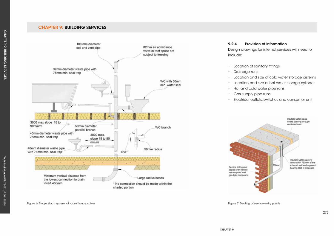
CHAPTER 9: BUILDING SERVICESCH
APTER 9: BU
ILDIN
G SERV
ICES
Tec
hn
ica
l Ma
nua
l V7: TS-011a
-7.00-180814
CHAPTER 9
273
Figure 6: Single stack system: air admittance valves Figure 7: Sealing of service entry points
9.2.4 Provision of informationDesign drawings for internal services will need to
include:
• Location of sanitary fittings
• Drainage runs
• Location and size of cold water storage cisterns
• Location and size of hot water storage cylinder
• Hot and cold water pipe runs
• Gas supply pipe runs
• Electrical outlets, switches and consumer unit
Tec
hn
ica
l Ma
nua
l V6: TS-011a
-6.00-010413Te
ch
nic
al M
anu
al V
7: TS-011a-7.00-180814
FUNCTIONAL REQUIREMENTS
9.3 eLeCTriCAL insTALLATions
Workmanshipi. All workmanship must be within the tolerances defined in Chapter 1
of this Manual.
ii. All work is to be carried out by a technically competent person in
a workmanlike manner.
iii. Certification is required for any work completed by an approved
installer.
Materialsi. All materials should be stored correctly in a manner that will not cause
damage or deterioration of the product.
ii. All materials, products and building systems shall be appropriate and
suitable for their intended purpose.
iii. The structure shall, unless specifically agreed otherwise with the
Warranty provider, have a life of not less than 60 years. Individual
components and assemblies, not integral to the structure, may have a
lesser durability, but not in any circumstances less than 15 years.
Designi. The design and specifications shall provide a clear indication of the
design intent and demonstrate a satisfactory level of performance.
ii. The materials, design and installation must meet the relevant
Building Regulations, British Standards, Eurocodes and other statutory
requirements.
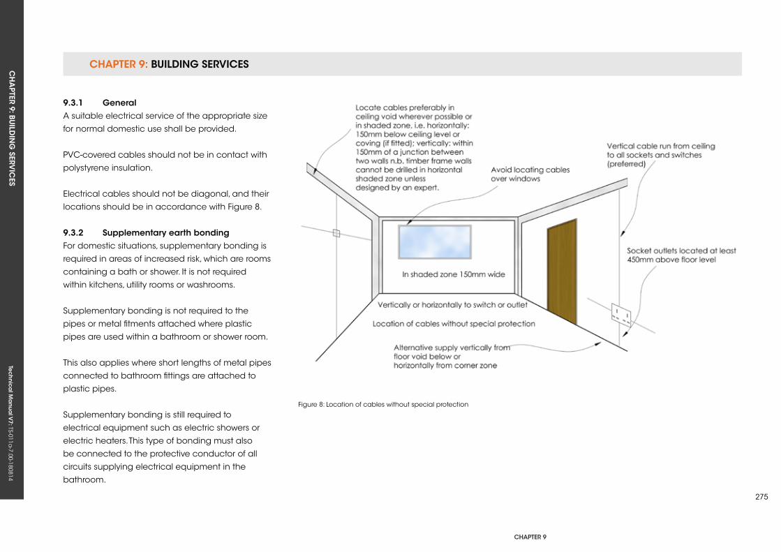
CHAPTER 9: BUILDING SERVICESCH
APTER 9: BU
ILDIN
G SERV
ICES
Tec
hn
ica
l Ma
nua
l V7: TS-011a
-7.00-180814
CHAPTER 9
275
Figure 8: Location of cables without special protection
9.3.1 generalA suitable electrical service of the appropriate size
for normal domestic use shall be provided.
PVC-covered cables should not be in contact with
polystyrene insulation.
Electrical cables should not be diagonal, and their
locations should be in accordance with Figure 8.
9.3.2 supplementary earth bondingFor domestic situations, supplementary bonding is
required in areas of increased risk, which are rooms
containing a bath or shower. It is not required
within kitchens, utility rooms or washrooms.
Supplementary bonding is not required to the
pipes or metal fitments attached where plastic
pipes are used within a bathroom or shower room.
This also applies where short lengths of metal pipes
connected to bathroom fittings are attached to
plastic pipes.
Supplementary bonding is still required to
electrical equipment such as electric showers or
electric heaters. This type of bonding must also
be connected to the protective conductor of all
circuits supplying electrical equipment in the
bathroom.
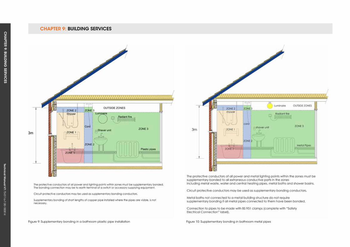
CHAPTER 9: BUILDING SERVICESCH
APTER 9: BU
ILDIN
G SERV
ICES
Tec
hn
ica
l Ma
nua
l V7: TS-011a
-7.00-180814
Figure 9: Supplementary bonding in a bathroom plastic pipe installation Figure 10: Supplementary bonding in bathroom metal pipes
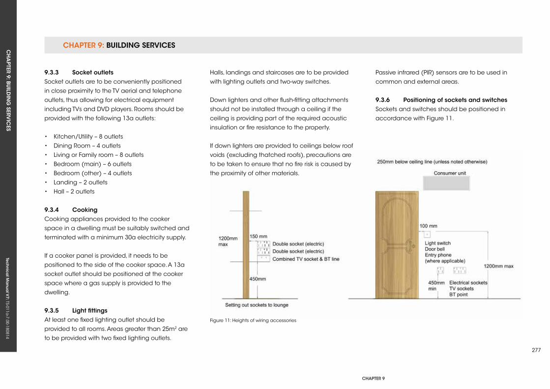
CHAPTER 9: BUILDING SERVICESCH
APTER 9: BU
ILDIN
G SERV
ICES
Tec
hn
ica
l Ma
nua
l V7: TS-011a
-7.00-180814
CHAPTER 9
277
Figure 11: Heights of wiring accessories
9.3.3 socket outletsSocket outlets are to be conveniently positioned
in close proximity to the TV aerial and telephone
outlets, thus allowing for electrical equipment
including TVs and DVD players. Rooms should be
provided with the following 13a outlets:
• kitchen/utility – 8 outlets
• Dining Room – 4 outlets
• Living or Family room – 8 outlets
• Bedroom (main) – 6 outlets
• Bedroom (other) – 4 outlets
• Landing – 2 outlets
• Hall – 2 outlets
9.3.4 CookingCooking appliances provided to the cooker
space in a dwelling must be suitably switched and
terminated with a minimum 30a electricity supply.
If a cooker panel is provided, it needs to be
positioned to the side of the cooker space. A 13a
socket outlet should be positioned at the cooker
space where a gas supply is provided to the
dwelling.
9.3.5 Light fittingsAt least one fixed lighting outlet should be
provided to all rooms. Areas greater than 25m2 are
to be provided with two fixed lighting outlets.
Halls, landings and staircases are to be provided
with lighting outlets and two-way switches.
Down lighters and other flush-fitting attachments
should not be installed through a ceiling if the
ceiling is providing part of the required acoustic
insulation or fire resistance to the property.
If down lighters are provided to ceilings below roof
voids (excluding thatched roofs), precautions are
to be taken to ensure that no fire risk is caused by
the proximity of other materials.
Passive infrared (PIR) sensors are to be used in
common and external areas.
9.3.6 Positioning of sockets and switchesSockets and switches should be positioned in
accordance with Figure 11.
Tec
hn
ica
l Ma
nua
l V6: TS-011a
-6.00-010413Te
ch
nic
al M
anu
al V
7: TS-011a-7.00-180814
FUNCTIONAL REQUIREMENTS
9.4 HeATing AnD MeCHAniCAL serviCes
Workmanshipi. All workmanship must be within the tolerances defined in Chapter 1
of this Manual.
ii. All work is to be carried out by a technically competent person in
a workmanlike manner.
iii. Certification is required for any work completed by an approved
installer.
Materialsi. All materials should be stored correctly in a manner that will not cause
damage or deterioration of the product.
ii. All materials, products and building systems shall be appropriate and
suitable for their intended purpose.
iii. The structure shall, unless specifically agreed otherwise with the
Warranty provider, have a life of not less than 60 years. Individual
components and assemblies, not integral to the structure, may have a
lesser durability, but not in any circumstances less than 15 years.
Designi. The design and specifications shall provide a clear indication of the
design intent and demonstrate a satisfactory level of performance.
ii. The materials, design and installation must meet the relevant
Building Regulations, British Standards, Eurocodes and other statutory
requirements.
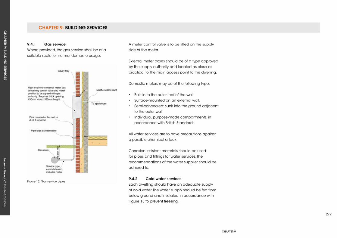
CHAPTER 9: BUILDING SERVICESCH
APTER 9: BU
ILDIN
G SERV
ICES
Tec
hn
ica
l Ma
nua
l V7: TS-011a
-7.00-180814
CHAPTER 9
279
Figure 12: Gas service pipes
9.4.1 gas serviceWhere provided, the gas service shall be of a
suitable scale for normal domestic usage.
A meter control valve is to be fitted on the supply
side of the meter.
External meter boxes should be of a type approved
by the supply authority and located as close as
practical to the main access point to the dwelling.
Domestic meters may be of the following type:
• Built-in to the outer leaf of the wall.
• Surface-mounted on an external wall.
• Semi-concealed: sunk into the ground adjacent
to the outer wall.
• Individual, purpose-made compartments, in
accordance with British Standards.
All water services are to have precautions against
a possible chemical attack.
Corrosion-resistant materials should be used
for pipes and fittings for water services. The
recommendations of the water supplier should be
adhered to.
9.4.2 Cold water servicesEach dwelling should have an adequate supply
of cold water. The water supply should be fed from
below ground and insulated in accordance with
Figure 13 to prevent freezing.

CHAPTER 9: BUILDING SERVICESCH
APTER 9: BU
ILDIN
G SERV
ICES
Tec
hn
ica
l Ma
nua
l V7: TS-011a
-7.00-180814
Figure 13: Insulation of incoming services
CHAPTER 9: BUILDING SERVICESCH
APTER 9: BU
ILDIN
G SERV
ICES
Tec
hn
ica
l Ma
nua
l V7: TS-011a
-7.00-180814
CHAPTER 9
281
Cold water systems may have provision for storage or be directly connected to the main supply. Drinking water needs to be supplied directly from the main supply.
Cold water pipes and storage cisterns located in roof spaces and other unheated areas should be appropriately insulated to the relevant standards.
Cold water storage cisterns will require the capacity specified in the design. Suitable support should be given for the cistern filled with water.
To stop the cistern bottom being deformed, permanent support is to be given where necessary. Adequate materials for support platforms are:
• Softwood boarding• Marine Plywood• Chipboard Type P5• Oriented Strand Board Type OSB3 to British Standards
All water tanks should be accessible. Gangway boarding is required to each cistern opening from the roof space access. An area of 1m2 of boarding is to be provided next to cisterns to permit routine maintenance.
Water storage cisterns should be protected from contamination by a rigid, close-fitting cover (which is not air tight) that excludes light and insects.
Holes should be formed with a cutter in the positions shown in the design.
Overflows in warning pipes should be no less than 19mm diameter and situated 25mm from the shut off water level in the cistern. The pipe may dip below the water level in accordance with water regulations. Alternatively, the pipe should terminate vertically downwards, or a tee should be fitted horizontally at the discharge end.
9.4.3 Hot water servicesHot water systems may have provision for storage or may be of the instantaneous type, e.g. combi boilers.
Vertical installation of cylinders is required with access, and cylinders are to be insulated as specified in the design.
Where an immersion heater is fitted, it should be:
• Appropriate for the type of water supplied to the dwelling.• Thermostatically controlled.• Located so that it can be withdrawn for replacement.• Fitted with an on/off switch.
Cisterns, vent pipes and all water services in unheated spaces should be insulated against freezing as specified in the design. Insulation is not to be placed below a cold waste tank where
it can benefit from heat from beneath. Tanks that are raised need to be insulated on all sides in an unheated roof space.
Fully insulated bends and junctions are required, especially near openings to the outside air, such as the eaves. If possible, water pipes should not be located within a loft space where they could be affected by cold ventilation air.
9.4.3.1 Provision for expansionAn expansion pipe is to be provided on vented systems for hot water.
9.4.3.2 unvented hot water systemsThird-party accreditation is required where an unvented hot water system with a storage capacity greater than 15 litres is required by the design. Installation is to be completed by a competent person.
9.4.3.3 Draining down facilityHot and cold water installations require the capability to be drained down.
9.4.4 use of materialsMaterials that are safe and minimise the risk of corrosion are to be used for pipes and fittings for water services. The recommendations of the water supplier with regard to materials and fittings should
be followed.
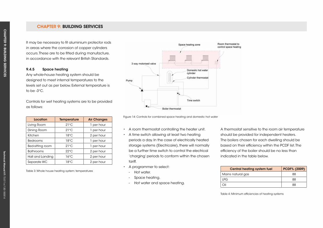
CHAPTER 9: BUILDING SERVICESCH
APTER 9: BU
ILDIN
G SERV
ICES
Tec
hn
ica
l Ma
nua
l V7: TS-011a
-7.00-180814
Figure 14: Controls for combined space heating and domestic hot water
Central heating system fuel PCDf% (2009)
Mains natural gas 88
LPG 88
Oil 88
Table 4: Minimum efficiencies of heating systems
It may be necessary to fit aluminium protector rods
in areas where the corrosion of copper cylinders
occurs. These are to be fitted during manufacture,
in accordance with the relevant British Standards.
9.4.5 space heatingAny whole-house heating system should be
designed to meet internal temperatures to the
levels set out as per below. External temperature is
to be -3°C.
Controls for wet heating systems are to be provided
as follows:
Location Temperature Air Changes
Living Room 21°C 1 per hour
Dining Room 21°C 1 per hour
kitchen 18°C 2 per hour
Bedrooms 18°C 1 per hour
Bed-sitting room 21°C 1 per hour
Bathrooms 22°C 2 per hour
Hall and Landing 16°C 2 per hour
Separate WC 18°C 2 per hour
Table 3: Whole house heating system: temperatures
• A room thermostat controlling the heater unit.
• A time switch allowing at least two heating
periods a day. In the case of electrically heated
storage systems (Electricaire), there will normally
be a further time switch to control the electrical
‘charging’ periods to conform within the chosen
tariff.
• A programmer to select:
- Hot water.
- Space heating.
- Hot water and space heating.
A thermostat sensitive to the room air temperature
should be provided for independent heaters.
The boilers chosen for each dwelling should be
based on their efficiency within the PCDF list. The
efficiency of the boiler should be no less than
indicated in the table below.
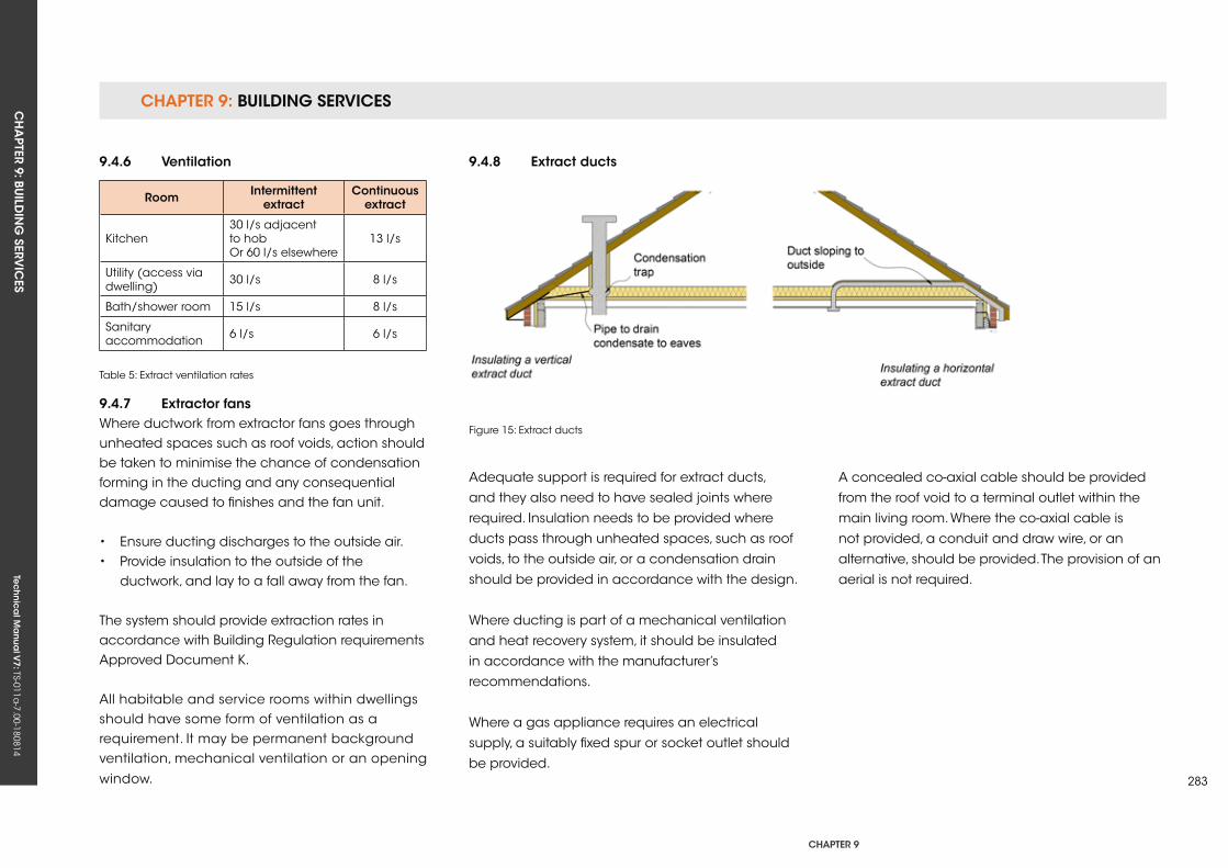
CHAPTER 9: BUILDING SERVICESCH
APTER 9: BU
ILDIN
G SERV
ICES
Tec
hn
ica
l Ma
nua
l V7: TS-011a
-7.00-180814
CHAPTER 9
283
Figure 15: Extract ducts
9.4.6 ventilation
room intermittent extract
Continuous extract
kitchen30 l/s adjacent to hobOr 60 l/s elsewhere
13 l/s
utility (access via dwelling) 30 l/s 8 l/s
Bath/shower room 15 l/s 8 l/s
Sanitary accommodation 6 l/s 6 l/s
Table 5: Extract ventilation rates
9.4.7 extractor fansWhere ductwork from extractor fans goes through unheated spaces such as roof voids, action should be taken to minimise the chance of condensation forming in the ducting and any consequential damage caused to finishes and the fan unit.
• Ensure ducting discharges to the outside air.• Provide insulation to the outside of the ductwork, and lay to a fall away from the fan.
The system should provide extraction rates in accordance with Building Regulation requirements Approved Document k.
All habitable and service rooms within dwellings should have some form of ventilation as a requirement. It may be permanent background ventilation, mechanical ventilation or an opening
window.
9.4.8 extract ducts
Adequate support is required for extract ducts,
and they also need to have sealed joints where
required. Insulation needs to be provided where
ducts pass through unheated spaces, such as roof
voids, to the outside air, or a condensation drain
should be provided in accordance with the design.
Where ducting is part of a mechanical ventilation
and heat recovery system, it should be insulated
in accordance with the manufacturer’s
recommendations.
Where a gas appliance requires an electrical
supply, a suitably fixed spur or socket outlet should
be provided.
A concealed co-axial cable should be provided
from the roof void to a terminal outlet within the
main living room. Where the co-axial cable is
not provided, a conduit and draw wire, or an
alternative, should be provided. The provision of an
aerial is not required.
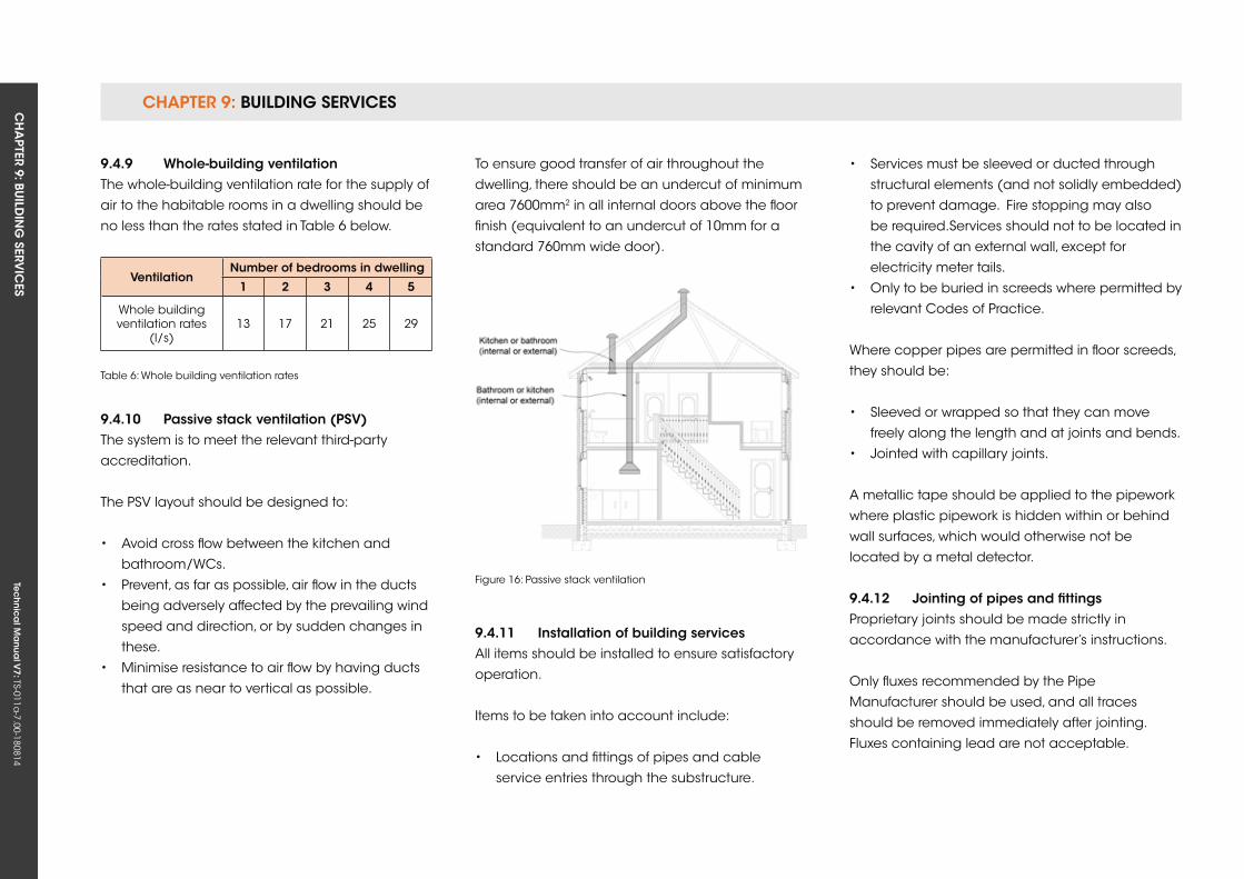
CHAPTER 9: BUILDING SERVICESCH
APTER 9: BU
ILDIN
G SERV
ICES
Tec
hn
ica
l Ma
nua
l V7: TS-011a
-7.00-180814
To ensure good transfer of air throughout the
dwelling, there should be an undercut of minimum
area 7600mm2 in all internal doors above the floor
finish (equivalent to an undercut of 10mm for a
standard 760mm wide door).
Figure 16: Passive stack ventilation
9.4.11 installation of building servicesAll items should be installed to ensure satisfactory
operation.
Items to be taken into account include:
• Locations and fittings of pipes and cable
service entries through the substructure.
ventilationnumber of bedrooms in dwelling
1 2 3 4 5
Whole building ventilation rates
(l/s)13 17 21 25 29
Table 6: Whole building ventilation rates
9.4.9 Whole-building ventilationThe whole-building ventilation rate for the supply of
air to the habitable rooms in a dwelling should be
no less than the rates stated in Table 6 below.
9.4.10 Passive stack ventilation (Psv)The system is to meet the relevant third-party
accreditation.
The PSV layout should be designed to:
• Avoid cross flow between the kitchen and
bathroom/WCs.
• Prevent, as far as possible, air flow in the ducts
being adversely affected by the prevailing wind
speed and direction, or by sudden changes in
these.
• Minimise resistance to air flow by having ducts
that are as near to vertical as possible.
• Services must be sleeved or ducted through
structural elements (and not solidly embedded)
to prevent damage. Fire stopping may also
be required.Services should not to be located in
the cavity of an external wall, except for
electricity meter tails.
• Only to be buried in screeds where permitted by
relevant Codes of Practice.
Where copper pipes are permitted in floor screeds,
they should be:
• Sleeved or wrapped so that they can move
freely along the length and at joints and bends.
• Jointed with capillary joints.
A metallic tape should be applied to the pipework
where plastic pipework is hidden within or behind
wall surfaces, which would otherwise not be
located by a metal detector.
9.4.12 Jointing of pipes and fittingsProprietary joints should be made strictly in
accordance with the manufacturer’s instructions.
Only fluxes recommended by the Pipe
Manufacturer should be used, and all traces
should be removed immediately after jointing.
Fluxes containing lead are not acceptable.
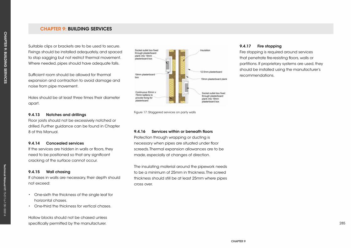
CHAPTER 9: BUILDING SERVICESCH
APTER 9: BU
ILDIN
G SERV
ICES
Tec
hn
ica
l Ma
nua
l V7: TS-011a
-7.00-180814
CHAPTER 9
285
9.4.16 services within or beneath floorsProtection through wrapping or ducting is
necessary when pipes are situated under floor
screeds. Thermal expansion allowances are to be
made, especially at changes of direction.
The insulating material around the pipework needs
to be a minimum of 25mm in thickness. The screed
thickness should still be at least 25mm where pipes
cross over.
Figure 17: Staggered services on party walls
Suitable clips or brackets are to be used to secure. Fixings should be installed adequately, and spaced to stop sagging but not restrict thermal movement. Where needed, pipes should have adequate falls.
Sufficient room should be allowed for thermal expansion and contraction to avoid damage and noise from pipe movement.
Holes should be at least three times their diameter apart.
9.4.13 notches and drillingsFloor joists should not be excessively notched or drilled. Further guidance can be found in Chapter 8 of this Manual.
9.4.14 Concealed servicesIf the services are hidden in walls or floors, they need to be positioned so that any significant cracking of the surface cannot occur.
9.4.15 Wall chasingIf chases in walls are necessary, their depth should not exceed:
• One-sixth the thickness of the single leaf for horizontal chases.• One-third the thickness for vertical chases.
Hollow blocks should not be chased unless
specifically permitted by the manufacturer.
9.4.17 fire stoppingFire stopping is required around services
that penetrate fire-resisting floors, walls or
partitions. If proprietary systems are used, they
should be installed using the manufacturer’s
recommendations.
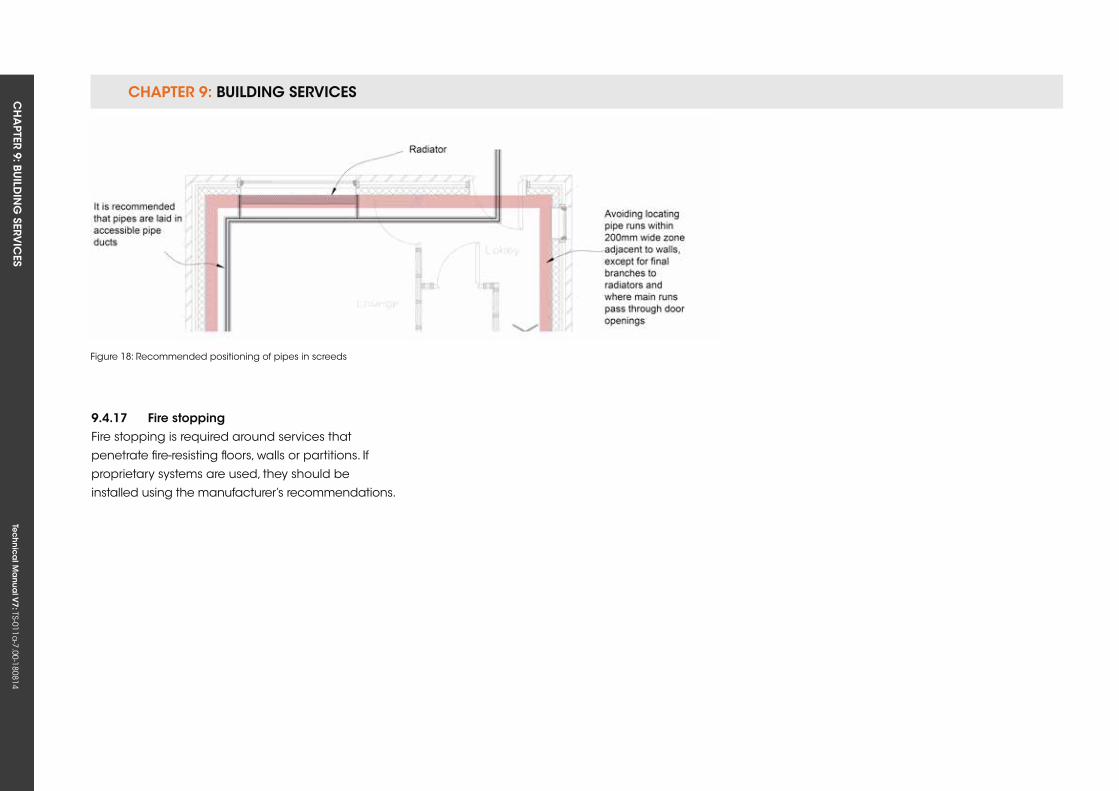
CHAPTER 9: BUILDING SERVICESCH
APTER 9: BU
ILDIN
G SERV
ICES
Tec
hn
ica
l Ma
nua
l V7: TS-011a
-7.00-180814
Figure 18: Recommended positioning of pipes in screeds
9.4.17 fire stoppingFire stopping is required around services that
penetrate fire-resisting floors, walls or partitions. If
proprietary systems are used, they should be
installed using the manufacturer’s recommendations.
CH
APTER 10: FIN
ISHES
Tec
hn
ica
l Ma
nua
l V7: TS-011a
-7.00-180814
CHAPTER 10
287
CHAPTer 10: finisHes
ConTenTs
10.1 PLASTERWORk
10.2 SECOND AND THIRD FIx FINISHES
Tec
hn
ica
l Ma
nua
l V6: TS-011a
-6.00-010413Te
ch
nic
al M
anu
al V
7: TS-011a-7.00-180814
FUNCTIONAL REQUIREMENTS
10.1 PLAsTerWork
Workmanshipi. All workmanship must be within the tolerances defined in Chapter 1
of this Manual.
ii. All work is to be carried out by a technically competent person in
a workmanlike manner.
Materialsi. All materials should be stored correctly in a manner that will not cause
damage or deterioration of the product.
ii. All materials, products and building systems shall be appropriate and
suitable for their intended purpose.
iii. The structure shall, unless specifically agreed otherwise with the
Warranty provider, have a life of not less than 60 years. Individual
components and assemblies, not integral to the structure, may have
a lesser durability, but not in any circumstances less than 15 years.
Designi. The design and specifications shall provide a clear indication of the
design intent and demonstrate a satisfactory level of performance.
ii. Surfaces that will be subjected to water from the use of a showerhead
over a bath should be tiled or have an appropriate alternative water-
resistant finish.
iii. The materials and construction must meet the relevant Building
Regulations, British standards, Eurocodes and other statutory
requirements.
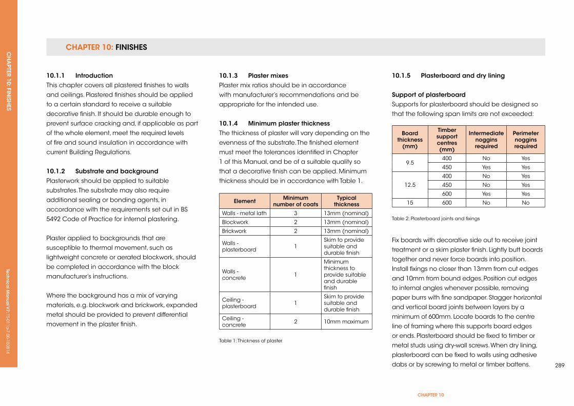
CHAPTER 10: FINISHESCH
APTER 10: FIN
ISHES
Tec
hn
ica
l Ma
nua
l V7: TS-011a
-7.00-180814
CHAPTER 10
289
10.1.1 introductionThis chapter covers all plastered finishes to walls
and ceilings. Plastered finishes should be applied
to a certain standard to receive a suitable
decorative finish. It should be durable enough to
prevent surface cracking and, if applicable as part
of the whole element, meet the required levels
of fire and sound insulation in accordance with
current Building Regulations.
10.1.2 substrate and backgroundPlasterwork should be applied to suitable
substrates. The substrate may also require
additional sealing or bonding agents, in
accordance with the requirements set out in BS
5492 Code of Practice for internal plastering.
Plaster applied to backgrounds that are
susceptible to thermal movement, such as
lightweight concrete or aerated blockwork, should
be completed in accordance with the block
manufacturer’s instructions.
Where the background has a mix of varying
materials, e.g. blockwork and brickwork, expanded
metal should be provided to prevent differential
movement in the plaster finish.
10.1.3 Plaster mixesPlaster mix ratios should be in accordance
with manufacturer’s recommendations and be
appropriate for the intended use.
10.1.4 Minimum plaster thicknessThe thickness of plaster will vary depending on the
evenness of the substrate. The finished element
must meet the tolerances identified in Chapter
1 of this Manual, and be of a suitable quality so
that a decorative finish can be applied. Minimum
thickness should be in accordance with Table 1.
element Minimum number of coats
Typical thickness
Walls - metal lath 3 13mm (nominal)
Blockwork 2 13mm (nominal)
Brickwork 2 13mm (nominal)
Walls - plasterboard 1
Skim to provide suitable and durable finish
Walls - concrete 1
Minimum thickness to provide suitable and durable finish
Ceiling - plasterboard 1
Skim to provide suitable and durable finish
Ceiling - concrete 2 10mm maximum
Table 1: Thickness of plaster
10.1.5 Plasterboard and dry lining
support of plasterboardSupports for plasterboard should be designed so
that the following span limits are not exceeded:
Board thickness
(mm)
Timber support centres (mm)
intermediate noggins required
Perimeter noggins required
9.5400 No yes
450 yes yes
12.5
400 No yes
450 No yes
600 yes yes
15 600 No No
Table 2: Plasterboard joints and fixings
Fix boards with decorative side out to receive joint
treatment or a skim plaster finish. Lightly butt boards
together and never force boards into position.
Install fixings no closer than 13mm from cut edges
and 10mm from bound edges. Position cut edges
to internal angles whenever possible, removing
paper burrs with fine sandpaper. Stagger horizontal
and vertical board joints between layers by a
minimum of 600mm. Locate boards to the centre
line of framing where this supports board edges
or ends. Plasterboard should be fixed to timber or
metal studs using dry-wall screws. When dry lining,
plasterboard can be fixed to walls using adhesive
dabs or by screwing to metal or timber battens.

CHAPTER 10: FINISHESCH
APTER 10: FIN
ISHES
Tec
hn
ica
l Ma
nua
l V7: TS-011a
-7.00-180814
Alternatively, a proprietary wall system can be
used, providing it has third-party certification. Gaps
between boards should not exceed 3mm and
consideration should be given to sealing all gaps
to improve dwelling air tightness.

Tec
hn
ica
l Ma
nua
l V6: TS-011a
-6.00-010413Te
ch
nic
al M
anu
al V
7: TS-011a-7.00-180814
FUNCTIONAL REQUIREMENTS
291
10.2 seConD AnD THirD fix finisHes
Workmanshipi. All workmanship must be within the tolerances defined in Chapter 1
of this Manual.
ii. All work is to be carried out by a technically competent person in
a workmanlike manner.
Materialsi. All materials should be stored correctly in a manner that will not cause
damage or deterioration of the product.
ii. All materials, products and building systems shall be appropriate and
suitable for their intended purpose.
iii. The structure shall, unless specifically agreed otherwise with the
Warranty provider, have a life of not less than 60 years. Individual
components and assemblies, not integral to the structure, may have
a lesser durability, but not in any circumstances less than 15 years.
Designi. The design and specifications shall provide a clear indication of the
design intent and demonstrate a satisfactory level of performance.
ii. The materials, design and construction must meet the relevant
Building Regulations, British Standards, Eurocodes and other statutory
requirements.
CHAPTer 10
CHAPTER 10: FINISHESCH
APTER 10: FIN
ISHES
Tec
hn
ica
l Ma
nua
l V7: TS-011a
-7.00-180814
10.2.1 Ceramic wall tiling
10.2.1.1 introduction Tiles should be fit for purpose, have a suitable finish
and be of an appropriate size and thickness.
10.2.1.2 Background surfacesBackground surfaces should be adequate to
support ceramic tiles, and as a minimum should:
• Be even, to adequately support the whole tile.
• Be strong and durable enough to support the
tile.
• Have sufficient absorbency to ensure that
adhesives will stick effectively or a suitable
bonding agent applied.
• Be of the same construction type; where two
construction types are present, e.g. blockwork
and timber stud, light reinforcing should be
provided over the junction between the two
types.
10.2.1.3 fixingDepending on the background, tiles should be
fixed using cement mortar or a suitable adhesive
purposely designed for ceramic tiling. Tiles to
shower enclosures and other areas that will be
exposed to water should be fixed with waterproof
adhesive.
10.2.1.4 groutingFor shower enclosures where tiling can be
saturated, grouting should be cement-based,
epoxy resin or a proprietary waterproof product.
A sealing method should be specified for the joint
between sanitary fittings and adjacent tiling. This is
particularly important where movement can take
place, e.g. where timber floors are used.
Ensure that design and specification information
is issued to Site Supervisors and relevant specialist
subcontractors and/or suppliers.
10.2.1.5 Ceramic floor tilingTile floorings shall provide a suitable surface and
be fit for purpose.
10.2.1.6 Background surfacesBackground surfaces should be adequate to
support ceramic tiles, and as a minimum should
be:
• Level and even enough to provide a plane
surface; falls should be specified where required.
• Resistant to ground moisture; a Damp Proof
Membrane (DPM) should be provided to a
ground bearing slab.
• Adequately dry, i.e. at least six weeks drying out
time for concrete base, three weeks for screed.
10.2.1.7 Tiles on wood-based substrateThe floor must be fit for purpose and should
have adequate stiffness to support the tiles and
adhesive.
For floors supported by joists up to 600mm centres,
the floor decking should be:
• 18mm exterior grade plywood screwed to the
joists at 300mm centres with all square edges
supported on joists or noggins. Plywood should
be laid with a 1.5mm–2mm movement gap
between boards and at abutments.
• Chipboard floor decking overlaid with a
minimum 10mm exterior grade plywood fixed to
joists at 300mm centres, or proprietary
separating/de-coupling layers, tile backer
boards or tile bedding reinforcement sheets
used in accordance with the manufacturer’s
recommendations.
• Tiles should be suitable for laying over a
timber base and deformable (flexible) tile
adhesive (e.g. C2S1), and grout should be used
in accordance with the adhesive
manufacturer’s recommendations.
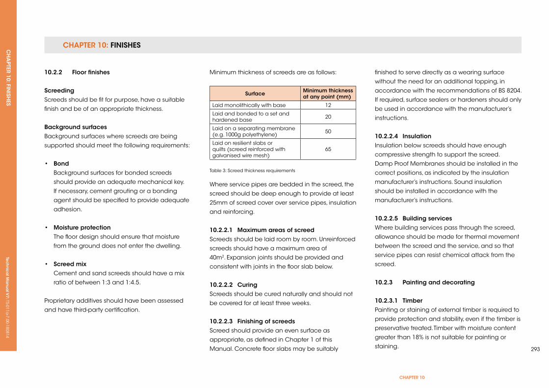
CHAPTER 10: FINISHESCH
APTER 10: FIN
ISHES
Tec
hn
ica
l Ma
nua
l V7: TS-011a
-7.00-180814
CHAPTER 10
293
10.2.2 floor finishes
screedingScreeds should be fit for purpose, have a suitable
finish and be of an appropriate thickness.
Background surfacesBackground surfaces where screeds are being
supported should meet the following requirements:
• Bond Background surfaces for bonded screeds
should provide an adequate mechanical key.
If necessary, cement grouting or a bonding
agent should be specified to provide adequate
adhesion.
• Moisture protection The floor design should ensure that moisture
from the ground does not enter the dwelling.
• screed mix Cement and sand screeds should have a mix
ratio of between 1:3 and 1:4.5.
Proprietary additives should have been assessed
and have third-party certification.
Where service pipes are bedded in the screed, the
screed should be deep enough to provide at least
25mm of screed cover over service pipes, insulation
and reinforcing.
10.2.2.1 Maximum areas of screedScreeds should be laid room by room. unreinforced
screeds should have a maximum area of
40m2. Expansion joints should be provided and
consistent with joints in the floor slab below.
10.2.2.2 CuringScreeds should be cured naturally and should not
be covered for at least three weeks.
10.2.2.3 finishing of screedsScreed should provide an even surface as
appropriate, as defined in Chapter 1 of this
Manual. Concrete floor slabs may be suitably
Minimum thickness of screeds are as follows:
surface Minimum thickness at any point (mm)
Laid monolithically with base 12
Laid and bonded to a set and hardened base 20
Laid on a separating membrane (e.g. 1000g polyethylene) 50
Laid on resilient slabs or quilts (screed reinforced with galvanised wire mesh)
65
Table 3: Screed thickness requirements
finished to serve directly as a wearing surface
without the need for an additional topping, in
accordance with the recommendations of BS 8204.
If required, surface sealers or hardeners should only
be used in accordance with the manufacturer’s
instructions.
10.2.2.4 insulationInsulation below screeds should have enough
compressive strength to support the screed.
Damp Proof Membranes should be installed in the
correct positions, as indicated by the insulation
manufacturer’s instructions. Sound insulation
should be installed in accordance with the
manufacturer’s instructions.
10.2.2.5 Building servicesWhere building services pass through the screed,
allowance should be made for thermal movement
between the screed and the service, and so that
service pipes can resist chemical attack from the
screed.
10.2.3 Painting and decorating
10.2.3.1 TimberPainting or staining of external timber is required to
provide protection and stability, even if the timber is
preservative treated. Timber with moisture content
greater than 18% is not suitable for painting or
staining.
CHAPTER 10: FINISHESCH
APTER 10: FIN
ISHES
Tec
hn
ica
l Ma
nua
l V7: TS-011a
-7.00-180814
The paint and stain systems specified should be
compatible with any timber preservatives and
timber species used.
Where windows and doors are to be stained,
proprietary sealants and beads should be
used in glazing rebates in accordance with the
manufacturer’s instructions as an alternative to
linseed oil putty.
stainingTimber should be stained in accordance with the
manufacturer’s recommendations.
PaintingPainting of timber should consist of at least
one primer coat, one undercoat and one finish
coat, or alternatively in accordance with the
manufacturer’s instructions.
10.2.3.2 Masonry and renderingExternal brickwork and render should be dry
before paint is applied, and paint systems for
external brickwork or render should be applied in
accordance with the manufacturer’s instructions.
10.2.3.3 MetalInternal and external structural steel should be
protected with at least two coats of zinc phosphate
primer. A decorative paint finish may then be
applied.
Internal and external steel that has been
galvanised to a rate of at least 450g/m2 is
acceptable without further protection. Steel
galvanised to a rate of less than 450g/m2 should
be protected with at least two coats of zinc
phosphate primer and a suitable decorative finish,
where required.
Intumescent paint coverings must be applied in
accordance with the manufacturer’s instructions.
10.2.3.4 Plaster and plasterboardPlaster and plasterboard surfaces should be
prepared and made ready for decorating in
accordance with the manufacturer’s instructions.
CH
APTER 11: EX
TERNA
L WO
RKS
Tec
hn
ica
l Ma
nua
l V7: TS-011a
-7.00-180814
CHAPTER 11
295
CHAPTer 11: exTernAL Works
ConTenTs
11.1 PAVING AND DRIVEWAyS
11.2 (THIS SECTION HAS BEEN REMOVED)
11.3 OuTBuILDINGS
Tec
hn
ica
l Ma
nua
l V6: TS-011a
-6.00-010413Te
ch
nic
al M
anu
al V
7: TS-011a-7.00-180814
FUNCTIONAL REQUIREMENTS
11.1 PAving AnD DriveWAys
Workmanshipi. All workmanship must be within the tolerances defined in Chapter 1
of this Manual.
ii. All work is to be carried out by a technically competent person in
a workmanlike manner.
Materialsi. All materials should be stored correctly in a manner that will not cause
damage or deterioration of the product.
ii. All materials, products and building systems shall be appropriate and
suitable for their intended purpose.
iii. The structure shall, unless specifically agreed otherwise with the
Warranty provider, have a life of not less than 60 years. Individual
components and assemblies, not integral to the structure, may have a
lesser durability, but not in any circumstances less than 15 years.
Designi. The design and specifications shall provide a clear indication of the
design intent and demonstrate a satisfactory level of performance.
ii. Structural elements outside the parameters of regional Approved
Documents must be supported by structural calculations provided by
a suitably qualified expert.
iii. The materials, design and construction must meet the relevant
Building Regulations, British Standards, Eurocodes and other statutory
requirements.
Limitations of functional requirementsThe Functional Requirements for external pathways and drives apply
only to the drive and pathway leading to the principle entrance to the
dwelling.
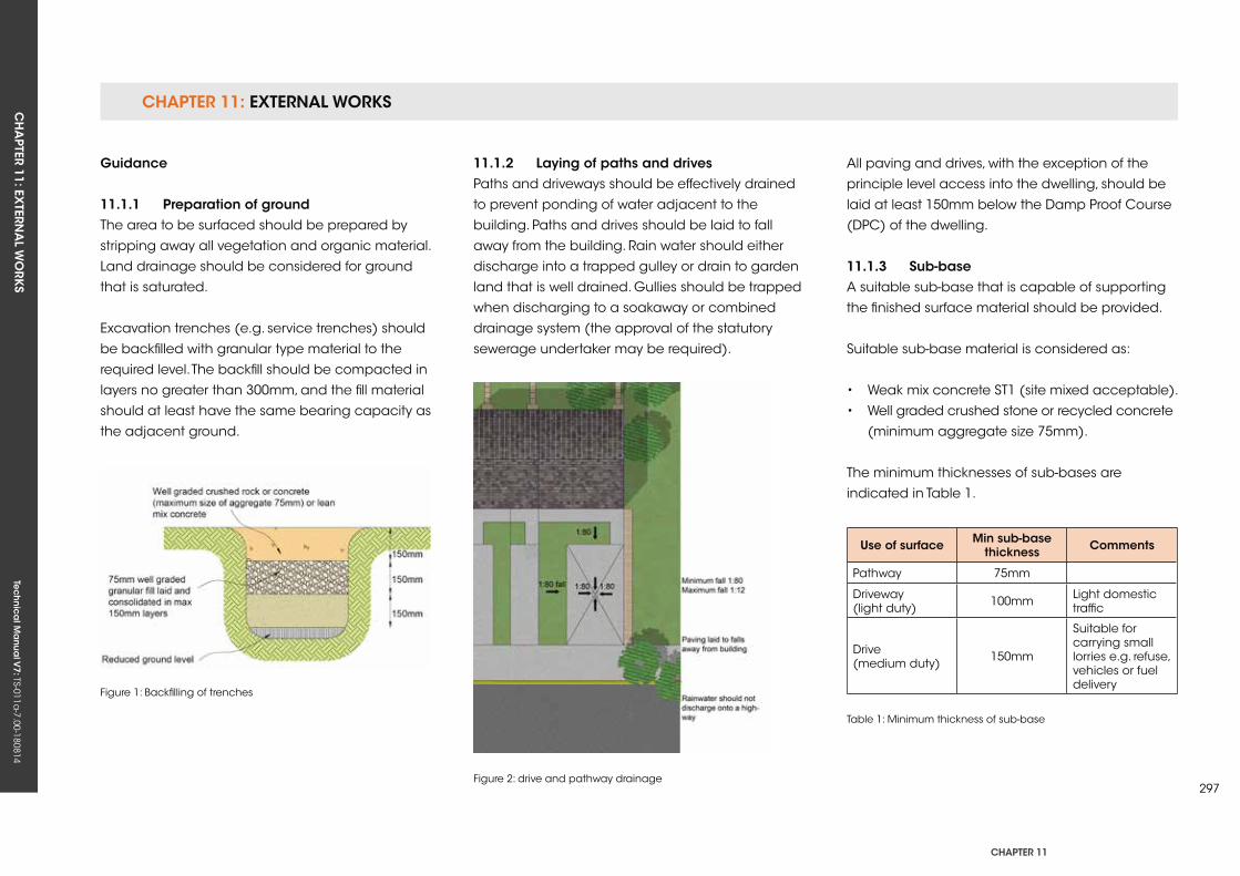
CHAPTER 11: EXTERNAL WORKSCH
APTER 11: EX
TERNA
L WO
RKS
Tec
hn
ica
l Ma
nua
l V7: TS-011a
-7.00-180814
CHAPTER 11
297
guidance
11.1.1 Preparation of groundThe area to be surfaced should be prepared by
stripping away all vegetation and organic material.
Land drainage should be considered for ground
that is saturated.
Excavation trenches (e.g. service trenches) should
be backfilled with granular type material to the
required level. The backfill should be compacted in
layers no greater than 300mm, and the fill material
should at least have the same bearing capacity as
the adjacent ground.
Figure 1: Backfilling of trenches
Figure 2: drive and pathway drainage
11.1.2 Laying of paths and drivesPaths and driveways should be effectively drained
to prevent ponding of water adjacent to the
building. Paths and drives should be laid to fall
away from the building. Rain water should either
discharge into a trapped gulley or drain to garden
land that is well drained. Gullies should be trapped
when discharging to a soakaway or combined
drainage system (the approval of the statutory
sewerage undertaker may be required).
All paving and drives, with the exception of the
principle level access into the dwelling, should be
laid at least 150mm below the Damp Proof Course
(DPC) of the dwelling.
11.1.3 sub-baseA suitable sub-base that is capable of supporting
the finished surface material should be provided.
Suitable sub-base material is considered as:
• Weak mix concrete ST1 (site mixed acceptable).
• Well graded crushed stone or recycled concrete
(minimum aggregate size 75mm).
The minimum thicknesses of sub-bases are
indicated in Table 1.
use of surface Min sub-base thickness Comments
Pathway 75mm
Driveway (light duty) 100mm Light domestic
traffic
Drive (medium duty) 150mm
Suitable for carrying small lorries e.g. refuse, vehicles or fuel delivery
Table 1: Minimum thickness of sub-base
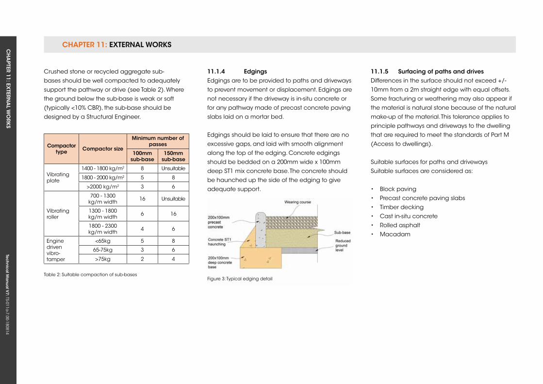
CHAPTER 11: EXTERNAL WORKSCH
APTER 11: EX
TERNA
L WO
RKS
Tec
hn
ica
l Ma
nua
l V7: TS-011a
-7.00-180814
Compactor type Compactor size
Minimum number of passes
100mm sub-base
150mm sub-base
Vibrating plate
1400 - 1800 kg/m2 8 unsuitable
1800 - 2000 kg/m2 5 8
>2000 kg/m2 3 6
Vibrating roller
700 - 1300 kg/m width 16 unsuitable
1300 - 1800 kg/m width 6 16
1800 - 2300 kg/m width 4 6
Engine driven vibro-tamper
<65kg 5 8
65-75kg 3 6
>75kg 2 4
Table 2: Suitable compaction of sub-bases
11.1.4 edgingsEdgings are to be provided to paths and driveways
to prevent movement or displacement. Edgings are
not necessary if the driveway is in-situ concrete or
for any pathway made of precast concrete paving
slabs laid on a mortar bed.
Edgings should be laid to ensure that there are no
excessive gaps, and laid with smooth alignment
along the top of the edging. Concrete edgings
should be bedded on a 200mm wide x 100mm
deep ST1 mix concrete base. The concrete should
be haunched up the side of the edging to give
adequate support.
Figure 3: Typical edging detail
11.1.5 surfacing of paths and drivesDifferences in the surface should not exceed +/-
10mm from a 2m straight edge with equal offsets.
Some fracturing or weathering may also appear if
the material is natural stone because of the natural
make-up of the material. This tolerance applies to
principle pathways and driveways to the dwelling
that are required to meet the standards of Part M
(Access to dwellings).
Suitable surfaces for paths and driveways
Suitable surfaces are considered as:
• Block paving
• Precast concrete paving slabs
• Timber decking
• Cast in-situ concrete
• Rolled asphalt
• Macadam
Crushed stone or recycled aggregate sub-
bases should be well compacted to adequately
support the pathway or drive (see Table 2). Where
the ground below the sub-base is weak or soft
(typically <10% CBR), the sub-base should be
designed by a Structural Engineer.
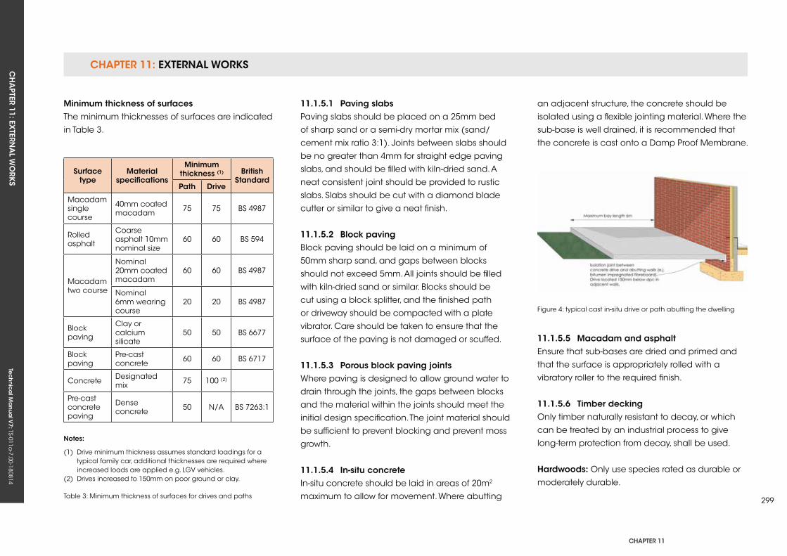
CHAPTER 11: EXTERNAL WORKSCH
APTER 11: EX
TERNA
L WO
RKS
Tec
hn
ica
l Ma
nua
l V7: TS-011a
-7.00-180814
CHAPTER 11
299
Minimum thickness of surfacesThe minimum thicknesses of surfaces are indicated
in Table 3.
11.1.5.1 Paving slabsPaving slabs should be placed on a 25mm bed
of sharp sand or a semi-dry mortar mix (sand/
cement mix ratio 3:1). Joints between slabs should
be no greater than 4mm for straight edge paving
slabs, and should be filled with kiln-dried sand. A
neat consistent joint should be provided to rustic
slabs. Slabs should be cut with a diamond blade
cutter or similar to give a neat finish.
11.1.5.2 Block pavingBlock paving should be laid on a minimum of
50mm sharp sand, and gaps between blocks
should not exceed 5mm. All joints should be filled
with kiln-dried sand or similar. Blocks should be
cut using a block splitter, and the finished path
or driveway should be compacted with a plate
vibrator. Care should be taken to ensure that the
surface of the paving is not damaged or scuffed.
11.1.5.3 Porous block paving jointsWhere paving is designed to allow ground water to
drain through the joints, the gaps between blocks
and the material within the joints should meet the
initial design specification. The joint material should
be sufficient to prevent blocking and prevent moss
growth.
11.1.5.4 in-situ concreteIn-situ concrete should be laid in areas of 20m2
maximum to allow for movement. Where abutting
Figure 4: typical cast in-situ drive or path abutting the dwelling
an adjacent structure, the concrete should be
isolated using a flexible jointing material. Where the
sub-base is well drained, it is recommended that
the concrete is cast onto a Damp Proof Membrane.
surface type
Material specifications
Minimum thickness (1) British
standardPath Drive
Macadam single course
40mm coated macadam 75 75 BS 4987
Rolled asphalt
Coarse asphalt 10mm nominal size
60 60 BS 594
Macadam two course
Nominal 20mm coated macadam
60 60 BS 4987
Nominal 6mm wearing course
20 20 BS 4987
Block paving
Clay or calcium silicate
50 50 BS 6677
Block paving
Pre-cast concrete 60 60 BS 6717
Concrete Designated mix 75 100 (2)
Pre-cast concrete paving
Dense concrete 50 N/A BS 7263:1
notes:
(1) Drive minimum thickness assumes standard loadings for a typical family car, additional thicknesses are required where increased loads are applied e.g. LGV vehicles.(2) Drives increased to 150mm on poor ground or clay.
Table 3: Minimum thickness of surfaces for drives and paths
11.1.5.5 Macadam and asphaltEnsure that sub-bases are dried and primed and
that the surface is appropriately rolled with a
vibratory roller to the required finish.
11.1.5.6 Timber deckingOnly timber naturally resistant to decay, or which
can be treated by an industrial process to give
long-term protection from decay, shall be used.
Hardwoods: Only use species rated as durable or
moderately durable.
CHAPTER 11: EXTERNAL WORKSCH
APTER 11: EX
TERNA
L WO
RKS
Tec
hn
ica
l Ma
nua
l V7: TS-011a
-7.00-180814
softwoods: Only use species/components with
natural durability or which have been treated
in accordance with BS EN 335 to a ‘use Class’
standard appropriate to their use, i.e. ‘use Class
4’ treatment for posts and other structural
components in direct ground or freshwater
contact, or ‘use Class 3’ treatment for all
components out of direct ground contact subject
to frequent wetting.
note:
• Whitewood should not be used for posts
embedded in the ground or for other elements
(joists) in the ground or other non-permeable
surface, e.g. concrete slab.
• All crosscuts, notches or large boreholes shall
be treated on site with a suitable preservative.
For full guidance on wood preservation
specification, contact the Wood Protection
Association.
Timber grade (strength class): C16 minimumThe grade (strength class) of timber used for
structural components such as posts, beams and
joists shall be sufficient to cope with the loads
placed upon it during its service life. Softwood
with a strength class rating of C16 is considered
the minimum standard for decks above 600mm
in height, and is a requirement of Building
Regulations for such raised-level structures. The
higher strength classes, typically C18 and C24,
should be specified where smaller component
sections, longer spans or commercial deck
performance design considerations are required.
For decks below 600mm in height, the use of C16
timber is also recommended.
Posts can be made from laminated sections, solid
timber or round poles, and should have a load-
bearing capability/size/spacing appropriate to the
scale and end use of the structure. For extended
life, the surface mounting of posts on precast piers
or metal shoes is recommended.
note:
• Do not exceed the recommended load
and span for each strength class; for detailed
recommendations, refer to span tables in TDA/
TRADA Timber Decking: The Professionals’
Manual.
• use ‘noggins’/blocking to strengthen frames
where appropriate to prevent flexing.
• Timber moisture content at installation: 20%
maximum.
To minimise the effects of shrinkage, e.g. cupping,
cracking, warping, etc., install timber as close as
possible to the equilibrium moisture content of the
site. For outdoor wood, moisture content varies from
19% in winter to 13% in summer in the uk. For best
results, always install wood with moisture content
lower than 20%. The stability of all wood used
outdoors can be improved by the use of water-
repellent treatments.
Board spacingWhen laying timber decking boards:
• Allow for a 5mm minimum to 8mm maximum
gap between board lengths.
• where the board abuts a post, allow a 5mm
gap.
• where board ends meet, allow a 3mm gap.
Metal fixingsAll metal fixings shall be made from corrosion-
resistant materials, such as stainless steel, hot
dipped, galvanised or other specialist coating.
Before use, verify with the manufacturer that the
fixings you have chosen are suitable for use with
treated timber. Aluminium fasteners should not be
used with treated wood. Prevent galvanic corrosion
by using the same type of metal for both fixings
and connectors.
Screws should be at least two-and-a-half times the
thickness of the board being fixed. Ideally, choose
screws that are self-countersinking. Pre-drilling pilot
holes will help prevent splitting, and always drill
pilot holes 2mm oversize when fixing hardwoods.
CHAPTER 11: EXTERNAL WORKSCH
APTER 11: EX
TERNA
L WO
RKS
Tec
hn
ica
l Ma
nua
l V7: TS-011a
-7.00-180814
CHAPTER 11
301
At all joist crossing points, secure boards with two
fixings positioned at the outer quarter points of
the deck board, i.e. 25% in from either edge. On
grooved boards, fixings should always be at the
bottom of grooves. Take care using high-pressure
nail guns as they can damage timber.
fallTo aid drainage, build a gentle fall of 1:100 into the
deck, away from any adjacent property. Grooved
deck boards are designed to assist the drainage of
surface water, so lay them in the direction of the fall.
11.1.6 further specification references
• TDA/TRADA Timber Decking: The Professionals’
Manual – second edition November 2006
• TDA Technical Bulletin TB 02: Statutory
requirements
• TDA Technical Bulletin TB 04: Parapet design and
construction
• TDA Technical Bulletin TB 08: Metal fixings
• TDA Code of Practice TDA/RD 08/01: Raised
timber decks on new homes – desired service
life 60 years
• Wood Protection Association: Timber
Preservation Manual
British standards The standards set out below all have a relevance
to the creation of high-performance timber decks.
Bs en 335-1 use classes of wood and wood-based products
against biological attack – Part 1: Classification of
use classes
Bs en 335-2 use classes of wood and wood-based products
against biological attack – Part 2: Guide to the
application of use classes to solid wood
Bs en 335-3 Durability of wood and wood-based products –
Definition of hazard classes of biological attack –
Part 3: Application to wood-based panels
Bs en 350-1 Durability of wood and wood-based products –
Natural durability of solid wood – Part 1: Guide to
the principles of testing and classification of the
natural durability of wood
Bs en 350-2 Durability of wood and wood-based products –
Natural durability of solid wood – Part 2: Guide to
natural durability and treatability of selected wood
species of importance in Europe
Bs en 351-1 Durability of wood and wood-based products –
Preservative-treated solid wood – Part 1: Classification
of preservative penetration and retention
Bs en 351-2 Durability of wood and wood-based products –
Preservative-treated solid wood – Part 2: Guidance
on sampling for the analysis of preservative-treated
wood
Bs en 460 Durability of wood and wood-based products
– Natural durability of solid wood: Guide to the
durability requirements for wood to be used in
hazard classes
Bs en 599-1 Durability of wood and wood-based products –
Performance of wood preservatives as determined
by biological tests – Part 1: Specification according
to hazard class
Bs 8417 Preservation of timber – Recommendations.
Guidance for specifiers on the treatment of timber
drawing on relevant sections of BS EN Standards
Bs 5756: 1985 Specification for visual strength grading of
hardwood
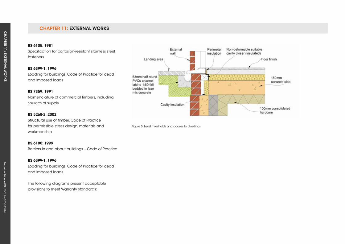
CHAPTER 11: EXTERNAL WORKSCH
APTER 11: EX
TERNA
L WO
RKS
Tec
hn
ica
l Ma
nua
l V7: TS-011a
-7.00-180814
Figure 5: Level thresholds and access to dwellings
Bs 6105: 1981 Specification for corrosion-resistant stainless steel
fasteners
Bs 6399-1: 1996 Loading for buildings. Code of Practice for dead
and imposed loads
Bs 7359: 1991 Nomenclature of commercial timbers, including
sources of supply
Bs 5268-2: 2002 Structural use of timber. Code of Practice
for permissible stress design, materials and
workmanship
Bs 6180: 1999 Barriers in and about buildings – Code of Practice
Bs 6399-1: 1996 Loading for buildings. Code of Practice for dead
and imposed loads
The following diagrams present acceptable
provisions to meet Warranty standards:

CHAPTER 11: EXTERNAL WORKSCH
APTER 11: EX
TERNA
L WO
RKS
Tec
hn
ica
l Ma
nua
l V7: TS-011a
-7.00-180814
CHAPTER 11
303
Figure 7: Level threshold: with canopy protection (block and beam floor)
Figure 6: Typical level threshold cast in-situ concrete slab
Tec
hn
ica
l Ma
nua
l V6: TS-011a
-6.00-010413Te
ch
nic
al M
anu
al V
7: TS-011a-7.00-180814
FUNCTIONAL REQUIREMENTS
seCTion 11.2
This section has been removed from the Technical Manual.

Tec
hn
ica
l Ma
nua
l V6: TS-011a
-6.00-010413Te
ch
nic
al M
anu
al V
7: TS-011a-7.00-180814
FUNCTIONAL REQUIREMENTS
305
11.3 ouTBuiLDings
Workmanshipi. All workmanship must be within the tolerances defined in Chapter 1
of this Manual.
ii. All work is to be carried out by a technically competent person in
a workmanlike manner.
Materialsi. All materials should be stored correctly in a manner that will not cause
damage or deterioration of the product.
ii. All materials, products and building systems shall be appropriate and
suitable for their intended purpose.
iii. The structure shall, unless specifically agreed otherwise with the
Warranty provider, have a life of not less than 60 years. Individual
components and assemblies, not integral to the structure, may have
a lesser durability, but not in any circumstances less than 15 years.
Designi. The design and specifications shall provide a clear indication of the
design intent and demonstrate a satisfactory level of performance.
ii. Outbuildings should be constructed to resist lateral and vertical loads
adequately.
iii. Foundations should be designed and constructed to suit local ground
conditions and adequately support the weight of the structure and
imposed loads.
iv. The materials and construction must meet the relevant Building
Regulations, British Standards, Eurocodes and other statutory
requirements.
CHAPTer 11
CHAPTER 11: EXTERNAL WORKSCH
APTER 11: EX
TERNA
L WO
RKS
Tec
hn
ica
l Ma
nua
l V7: TS-011a
-7.00-180814
11.3.1 LimitationsThis section does not apply to outbuildings where:
• The building is heated or protected against frost
damage.
• The building is used as a habitable space,
including home offices.
• It is essential that the walls will resist wind-driven
rain.
11.3.2 introductionIn order to achieve a satisfactory standard of
performance, garages, conservatories, small
outbuildings and extensions should be designed
and constructed so that:
• They are able to sustain and transmit all normal
loads to the ground without affecting their own
stability or that of the housing unit (or any
adjacent buildings) by excessive deflection
or deformation that would adversely affect
the appearance, value and serviceability of the
building or the housing unit.
• They provide an acceptable and durable
external surface and are not adversely affected
by harmful or toxic materials in the atmosphere
or from the ground.
• They are resistant to moisture and do not allow
the passage of moisture to parts of the building
that would be adversely affected by it.
• They encourage the rapid discharge of
moisture due to rain or snow from their surfaces
to suitable gutters and down pipes, or to
some other form of collection and discharge
that prevents moisture from re-entering the
building, where it might have adverse effects.
• In the event of fire, they resist fire spread to the
housing unit and to adjacent buildings.
• They are provided with sufficient locks or other
devices to resist unauthorised entry.
• Where additional services installations are
provided (such as central heating boilers or
electrical or plumbing installations), these
comply with Chapter 9 of this Manual.
• The risk of injury from accidental breakage of
the glazing (where fitted) is reduced to a
minimum.
A satisfactory performance for the design and
construction of garages, conservatories, small
outbuildings and extensions may be achieved
by meeting the relevant parts of the Approved
Documents.
11.3.3 foundationsFoundations should be constructed so that loads
are adequately transferred; further guidance can
be found in Chapter 5 of this Manual.
11.3.4 floorsFloors should have a minimum concrete thickness
of 100mm and bear onto a suitable sub-base. The
concrete should be float finished and to at least
a GEN3 grade. Further guidance can be found in
Chapter 6 of this Manual.
11.3.5 WallsSingle leaf 100mm walls are considered
acceptable, providing that the following provisions
are met:
• The height of wall does not exceed 2400mm
from ground level.
• Intermediate piers are provided, in accordance
with Figure 9.
• The wall is adequately restrained at ceiling and
verge level.
• The walls are capable of adequately
transferring the roof loadings to the foundation.
• Walls are pointed both internally and externally.
• Walls should be provided with a suitable DPC
located at least 150mm above ground level.
• Proprietary lintels should be provided over
window/door openings.
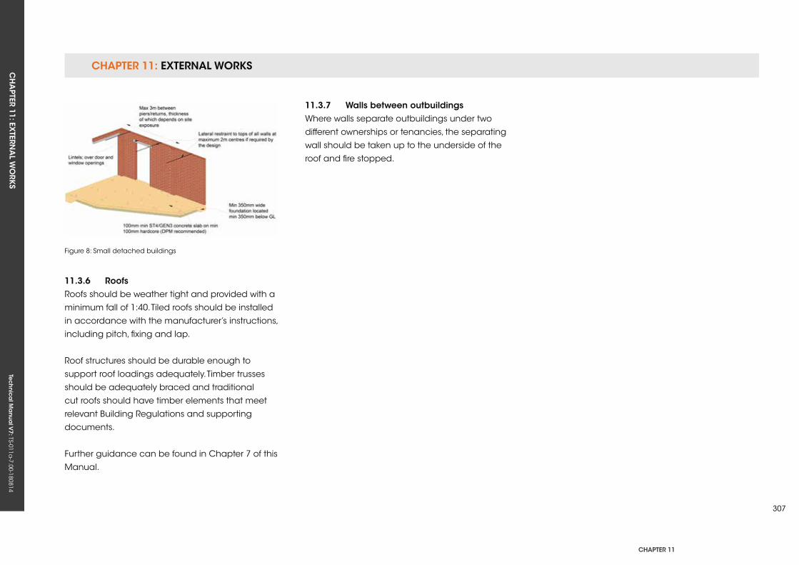
CHAPTER 11: EXTERNAL WORKSCH
APTER 11: EX
TERNA
L WO
RKS
Tec
hn
ica
l Ma
nua
l V7: TS-011a
-7.00-180814
CHAPTER 11
307
11.3.6 roofsRoofs should be weather tight and provided with a
minimum fall of 1:40. Tiled roofs should be installed
in accordance with the manufacturer’s instructions,
including pitch, fixing and lap.
Roof structures should be durable enough to
support roof loadings adequately. Timber trusses
should be adequately braced and traditional
cut roofs should have timber elements that meet
relevant Building Regulations and supporting
documents.
Further guidance can be found in Chapter 7 of this
Manual.
11.3.7 Walls between outbuildingsWhere walls separate outbuildings under two
different ownerships or tenancies, the separating
wall should be taken up to the underside of the
roof and fire stopped.
Figure 8: Small detached buildings

Tec
hn
ica
l Ma
nua
l V6: TS-011a
-6.00-010413Te
ch
nic
al M
anu
al V
7: TS-011a-7.00-180814
CH
APTER 12: C
ON
VERSIO
N A
ND
REFURBISH
MEN
TTe
ch
nic
al M
anu
al V
7: TS-011a-7.00-180814
CHAPTER 12
309
CHAPTer 12: Conversion AnD refurBisHMenT
ConTenTs
12.1 ExISTING ELEMENTS
12.2 NEW ELEMENTS CONNECTING TO ExISTING STRuCTuRE
Tec
hn
ica
l Ma
nua
l V6: TS-011a
-6.00-010413Te
ch
nic
al M
anu
al V
7: TS-011a-7.00-180814
FUNCTIONAL REQUIREMENTS
12.1 exisTing eLeMenTs
Workmanshipi. All workmanship is to be completed by a technically competent
person in a workmanlike manner.
ii. Any new work must meet the tolerances defined in Chapter 1 of this
Manual. Tolerances will not apply to existing finishes that have not
been upgraded or altered, or where the supporting elements will not
allow for the tolerances to be met.
Materialsi. All new materials should be stored correctly in a manner that will not
cause damage or deterioration of the product.
ii. Materials, products and building systems shall be appropriate and
suitable for their intended purpose.
iii. The structure, regardless of whether it is a new or existing element,
shall, unless specifically agreed otherwise with the Warranty provider,
have a life of not less than 60 years. Individual components and
assemblies, not integral to the structure, may have a lesser durability,
but not in any circumstances under 15 years
iv. Existing elements that are to be retained must provide a ‘waterproof
envelope’ to the building and be structurally adequate.
Designi. The design and specifications should give clear indication of the
design intent and demonstrate a satisfactory level of performance
with regards the renovation of components and the interaction of new
elements.
ii. Specialist reports are required to confirm that existing elements will
have an adequate level of structural stability, as defined in the Materials
section above; the reports must confirm the adequacy of the existing
‘waterproof envelope’.
CHAPTER 12: CONVERSION AND REFURBISHMENTCH
APTER 12: C
ON
VERSIO
N A
ND
REFURBISH
MEN
T Te
ch
nic
al M
anu
al V
7: TS-011a-7.00-180814
CHAPTER 12
311
12.1.1 introductionThe following guidance has been formulated to
assist both Warranty Surveyors and Developers
on projects involving either the conversion or
refurbishment of existing buildings.
Conversions and refurbishments are projects that
involve work to existing buildings or parts of existing
buildings. This could include the conversion of
industrial or commercial buildings into housing; the
conversion of an existing residential building into
flats; an additional storey to an existing building;
the refurbishment of an existing residential building;
or a façade retention project.
The Warranty includes cover for the retained structural elements and waterproof envelope of
any existing building for the duration of the policy.
The Warranty Surveyor will always undertake an
initial assessment of the existing fabric to ascertain
in general terms if the proposal is capable of
representing a standard risk to the underwriter. If
deemed acceptable, the development is then
subject to a technical audit process during
construction, and the following guidance is
intended to assist all parties in ensuring the
relevant requirements are met, as well as providing
an element of consistency in approach.
Depending on the condition of the original
building; an expert survey may be required for the
different elements of the building as described in
the following sections of this Chapter. If the survey
concludes that any of these elements are unable
to meet the life expectancy of 60 years for structure
and 15 years for non-structural elements, they
should be systematically replaced or repaired.
Existing buildings and structures can present
particular problems both initially and on an
ongoing basis. Therefore, it is essential that
thorough and comprehensive survey work is
undertaken prior to new works commencing to
understand both the current condition of any
structure and the impact any proposed works may
have. Although initially this may be considered
an unnecessary early expense, the savings in
reconstruction costs can greatly outweigh the cost
of the preparatory work.
Elements of the retained structure and proposed
works should not be considered in isolation, as
a solution for one problem may cause issues
elsewhere. Past performance is no guarantee of
ongoing adequate performance because different
expectations and changing living conditions can
all impact on both the actual and perceived
performance of a converted/refurbished structure.
It is not possible to cover every building type within
this Chapter; therefore, the guidance is general,
and certainly will not apply in every scenario. It
is strongly recommended that early discussions
are held to determine exact requirements and to
enable a full review of the proposed strategy and
development.
Where new work is proposed, it should follow the
guidance for those elements in this Technical
Manual. Where new work is applied to, or meets,
existing elements, consideration on how these
areas will interact must be made; for example, new
cavity masonry that abuts an existing solid wall
construction.
Please note that the requirements of the technical audit are quite different from those undertaken for the purposes of compliance with Building Control and planning legislation. if any such bodies have imposed restrictions on the areas above, we suggest that you contact the Technical services Department before undertaking any works.
CHAPTER 12: CONVERSION AND REFURBISHMENTCH
APTER 12: C
ON
VERSIO
N A
ND
REFURBISH
MEN
TTe
ch
nic
al M
anu
al V
7: TS-011a-7.00-180814
12.1.2 retained elements, foundations and load-bearing structures (including floors, walls and roofs)Any areas of cracking or suspected movement are
to be assessed, and remedial measures provided
by an appropriately qualified and experienced
Structural Engineer. Any additional loads must
be catered for. Consideration of the impact of
any landscaping and drainage works is required.
Spalling masonry can be locally repaired, with units
cut out and replaced, or re-used with sound face
showing. Larger areas will require a schedule of
repair to be submitted and agreed.
Damp Proof Courses (DPC) and membranes All walls, floors and basements should include
a DPC. Ground levels and ventilation should be
checked before any remedial DPC treatments
are considered. However, where remedial
DPC treatments are required, these need to
be appropriate to the type of construction,
independently tested/approved and provided with
a 10 year insurance-backed guarantee. Installed
by a member of the Property Care Association,
the guarantees must cover workmanship and
materials. The construction of any existing ground
floor will need to be assessed, and details provided
to the Warranty Surveyor for consideration.
Timber treatment against insect and fungal attackAll retained timbers will need to be assessed,
logged and the remedial treatment noted.
Timbers that are embedded should be exposed
or removed and replaced with masonry. Where
this is not possible, core samples should be taken
to assess the moisture content, and remedial
works considered. Any remedial treatment must
be provided with a 10 year insurance-backed
guarantee and undertaken by a member of the
Property Care Association, where guarantees must
cover workmanship and materials.
roof coveringsCoverings and support systems should be
replaced unless a specialist report compiled by
an independent, competent and appropriately
experienced Chartered Building Surveyor
concludes that the system can provide a life
span of at least 15 years. This should include the
covering, battens, felt, flat roof decking, fascias,
soffits, flashings, nails and clips, etc.
Weather resistance of walls, including claddings, render, re-pointing, etc.The remedial works for the external walls must have
regard for the exposure rating provided in BS 5628.
Any retained cladding system must be surveyed
to determine a minimum 15 year life expectancy.
Provision of additional thermal insulation must also
be considered.
external doors and windows A condition survey should be provided by an
independent, competent and appropriately
qualified Surveyor or Specialist to confirm life
expectancy of 15 years. Consideration must be
given to improving the thermal characteristics.
External and internal services
Any services to be retained should be suitably
tested and reported by a Specialist.
Drainage A CCTV survey should be undertaken to ensure the
integrity and design of any retained system. Where
the lengths of existing retained drainage do not
have rodding access in accordance with current
requirements, additional access points should be
provided. Inspection chambers and manholes
located within habitable parts of the building will
not normally be acceptable. Existing interceptors
should be removed, and any proposal to retain
existing septic tanks/cesspools will normally be
rejected.
Where some of the elements are new and
replaced as part of the conversion/refurbishment,
no report is necessary.
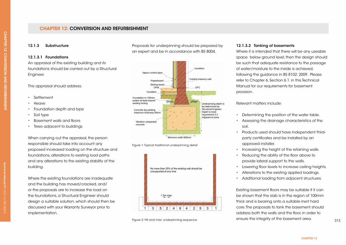
CHAPTER 12: CONVERSION AND REFURBISHMENTCH
APTER 12: C
ON
VERSIO
N A
ND
REFURBISH
MEN
T Te
ch
nic
al M
anu
al V
7: TS-011a-7.00-180814
CHAPTER 12
313
12.1.3 substructure
12.1.3.1 foundationsAn appraisal of the existing building and its
foundations should be carried out by a Structural
Engineer.
This appraisal should address:
• Settlement
• Heave
• Foundation depth and type
• Soil type
• Basement walls and floors
• Trees adjacent to buildings
When carrying out the appraisal, the person
responsible should take into account any
proposed increased loading on the structure and
foundations, alterations to existing load paths
and any alterations to the existing stability of the
building.
Where the existing foundations are inadequate
and the building has moved/cracked, and/
or the proposals are to increase the load on
the foundations, a Structural Engineer should
design a suitable solution, which should then be
discussed with your Warranty Surveyor prior to
implementation.
Proposals for underpinning should be prepared by
an expert and be in accordance with BS 8004.
Figure 1: Typical traditional underpinning detail
Figure 2:‘Hit and miss’ underpinning sequence
12.1.3.2 Tanking of basementsWhere it is intended that there will be any useable
space below ground level, then the design should
be such that adequate resistance to the passage
of water/moisture to the inside is achieved,
following the guidance in BS 8102: 2009. Please
refer to Chapter 6, Section 6.1. in this Technical
Manual for our requirements for basement
provision.
Relevant matters include:
• Determining the position of the water table.
• Assessing the drainage characteristics of the
soil.
• Products used should have independent third-
party certificates and be installed by an
approved installer.
• Increasing the height of the retaining walls.
• Reducing the ability of the floor above to
provide lateral support to the walls.
• Lowering floor levels to increase ceiling heights.
• Alterations to the existing applied loadings.
• Additional loading from adjacent structures.
Existing basement floors may be suitable if it can
be shown that the slab is in the region of 100mm
thick and is bearing onto a suitable inert hard
core. The proposals to tank the basement should
address both the walls and the floor, in order to
ensure the integrity of the basement area.
CHAPTER 12: CONVERSION AND REFURBISHMENTCH
APTER 12: C
ON
VERSIO
N A
ND
REFURBISH
MEN
TTe
ch
nic
al M
anu
al V
7: TS-011a-7.00-180814
It should not be assumed that a wall that is dry at
the time of the survey will not cause a problem in
future. Existing basements should be provided with
a new structural waterproofing (tanking) system
designed by a suitably qualified and experienced
waterproofing Specialist. The work should be
carried out by a competent Specialist Contractor
who has been approved by the Warranty Surveyor
and is a member of the Structural Waterproofing
Group. Land drainage to the external perimeter
of the basement must be considered in order to
reduce hydrostatic pressure to acceptable levels.
Internal walls will also require tanking if they do not
have an effective DPC located at the same level as
the floor tanking membrane or if they link with an
external wall that is in contact with the adjacent
ground.
Built-in structural timbers, such as timber lintels, shall
be replaced, e.g. with concrete lintels, if they are
sealed by tanking.
It should be ensured that continuity of tanking is
maintained around chimney breasts. To simplify
the problem, consideration should be given to the
removal of the chimney breast in the basement
and providing adequate support at ground level to
the retained chimney.
In accordance with BS 8102: 2009, adequate
provision should be made to prevent surface and
interstitial condensation within the basement.
Consideration must be given to:
• Appropriate ventilation
• Adequate heating
• Appropriate insulation
• Avoiding cold bridging
• Treatment of hygroscopic salts contained in
walls and floors
• Removal of water vapour from kitchens and
bathrooms
12.1.3.3 Damp proofingWhere an existing DPC cannot be identified or is
found to be defective, a remedial DPC should be
provided; it should have an insurance-backed
guarantee and be installed by a Property Care
Association Member. A suitable DPC should be
provided to existing walls, placed at least 150mm
above external ground level to ensure that ground
moisture does not enter the inside of the building.
Consideration must be given to the height of the
ground floor.
Some types of wall are not suitable for treatment by
a remedial DPC system. These include:
• Walls of exceptional thickness, i.e. greater than
600mm.
• Rubble-filled walls.
• Random flint/granite walls, or those of other
similar impermeable materials.
• Mud walls (cob), wattle and daub.
• Rat trap bond.
Advice should be sought from the Property Care
Association Member as to the suitability of their
proposed products/system. Products used in
chemically injected systems should always hold
current independent third-party certificates.
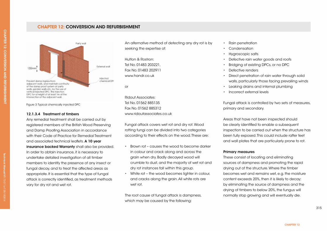
CHAPTER 12: CONVERSION AND REFURBISHMENTCH
APTER 12: C
ON
VERSIO
N A
ND
REFURBISH
MEN
T Te
ch
nic
al M
anu
al V
7: TS-011a-7.00-180814
CHAPTER 12
315
12.1.3.4 Treatment of timbers Any remedial treatment shall be carried out by
registered members of the British Wood Preserving
and Damp Proofing Association in accordance
with their Code of Practice for Remedial Treatment
and associated technical leaflets. A 10 year insurance backed Warranty shall also be provided.
In order to obtain insurance, it is necessary to
undertake detailed investigation of all timber
members to identify the presence of any insect or
fungal decay, and to treat the affected areas as
appropriate. It is essential that the type of fungal
attack is correctly identified, as treatment methods
vary for dry rot and wet rot.
Figure 3: Typical chemically injected DPC
An alternative method of detecting any dry rot is by
seeking the expertise of:
Hutton & Rostron:
Tel No. 01483 203221,
Fax No. 01483 202911
www.handr.co.uk
or
Ridout Associates:
Tel No. 01562 885135
Fax No. 01562 885312
www.ridoutassociates.co.uk
Fungal attack covers wet rot and dry rot. Wood
rotting fungi can be divided into two categories
according to their effects on the wood. These are:
• Brown rot – causes the wood to become darker
in colour and crack along and across the
grain when dry. Badly decayed wood will
crumble to dust, and the majority of wet rot and
dry rot instances fall within this group.
• White rot – the wood becomes lighter in colour,
and cracks along the grain. All white rots are
wet rot.
The root cause of fungal attack is dampness,
which may be caused by the following:
• Rain penetration
• Condensation
• Hygroscopic salts
• Defective rain water goods and roofs
• Bridging of existing DPCs, or no DPC
• Defective renders
• Direct penetration of rain water through solid
walls, particularly those facing prevailing winds
• Leaking drains and internal plumbing
• Incorrect external levels
Fungal attack is controlled by two sets of measures,
primary and secondary.
Areas that have not been inspected should
be clearly identified to enable a subsequent
inspection to be carried out when the structure has
been fully exposed. This could include rafter feet
and wall plates that are particularly prone to rot.
Primary measuresThese consist of locating and eliminating
sources of dampness and promoting the rapid
drying out of the structure. Where the timber
becomes wet and remains wet, e.g. the moisture
content exceeds 20%, then it is likely to decay;
by eliminating the source of dampness and the
drying of timbers to below 20%, the fungus will
normally stop growing and will eventually die.
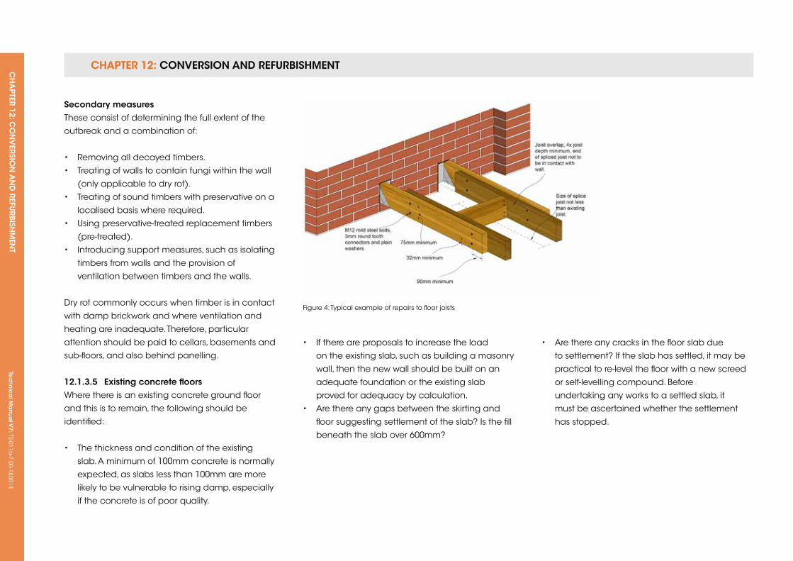
CHAPTER 12: CONVERSION AND REFURBISHMENTCH
APTER 12: C
ON
VERSIO
N A
ND
REFURBISH
MEN
TTe
ch
nic
al M
anu
al V
7: TS-011a-7.00-180814
secondary measuresThese consist of determining the full extent of the
outbreak and a combination of:
• Removing all decayed timbers.
• Treating of walls to contain fungi within the wall
(only applicable to dry rot).
• Treating of sound timbers with preservative on a
localised basis where required.
• using preservative-treated replacement timbers
(pre-treated).
• Introducing support measures, such as isolating
timbers from walls and the provision of
ventilation between timbers and the walls.
Dry rot commonly occurs when timber is in contact
with damp brickwork and where ventilation and
heating are inadequate. Therefore, particular
attention should be paid to cellars, basements and
sub-floors, and also behind panelling.
12.1.3.5 existing concrete floorsWhere there is an existing concrete ground floor
and this is to remain, the following should be
identified:
• The thickness and condition of the existing
slab. A minimum of 100mm concrete is normally
expected, as slabs less than 100mm are more
likely to be vulnerable to rising damp, especially
if the concrete is of poor quality.
Figure 4: Typical example of repairs to floor joists
• If there are proposals to increase the load
on the existing slab, such as building a masonry
wall, then the new wall should be built on an
adequate foundation or the existing slab
proved for adequacy by calculation.
• Are there any gaps between the skirting and
floor suggesting settlement of the slab? Is the fill
beneath the slab over 600mm?
• Are there any cracks in the floor slab due
to settlement? If the slab has settled, it may be
practical to re-level the floor with a new screed
or self-levelling compound. Before
undertaking any works to a settled slab, it
must be ascertained whether the settlement
has stopped.
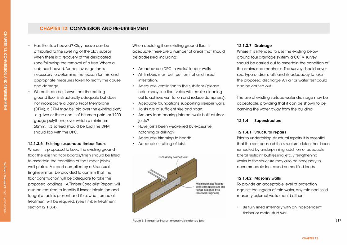
CHAPTER 12: CONVERSION AND REFURBISHMENTCH
APTER 12: C
ON
VERSIO
N A
ND
REFURBISH
MEN
T Te
ch
nic
al M
anu
al V
7: TS-011a-7.00-180814
CHAPTER 12
317
• Has the slab heaved? Clay heave can be
attributed to the swelling of the clay subsoil
when there is a recovery of the desiccated
zone following the removal of a tree. Where a
slab has heaved, further investigation is
necessary to determine the reason for this, and
appropriate measures taken to rectify the cause
and damage.
• Where it can be shown that the existing
ground floor is structurally adequate but does
not incorporate a Damp Proof Membrane
(DPM), a DPM may be laid over the existing slab,
e.g. two or three coats of bitumen paint or 1200
gauge polythene, over which a minimum
50mm, 1:3 screed should be laid. The DPM
should lap with the DPC.
12.1.3.6 existing suspended timber floorsWhere it is proposed to keep the existing ground
floor, the existing floor boards/finish should be lifted
to ascertain the condition of the timber joists/
wall plates. A report compiled by a Structural
Engineer must be provided to confirm that the
floor construction will be adequate to take the
proposed loadings. A Timber Specialist Report will
also be required to identify if insect infestation and
fungal attack is present and if so, what remedial
treatment will be required. (See Timber treatment
section12.1.3.4).
Figure 5: Strengthening an excessively notched joist
When deciding if an existing ground floor is
adequate, there are a number of areas that should
be addressed, including:
• An adequate DPC to walls/sleeper walls
• All timbers must be free from rot and insect
infestation.
• Adequate ventilation to the sub-floor (please
note, many sub-floor voids will require cleaning
out to achieve ventilation and reduce dampness).
• Adequate foundations supporting sleeper walls.
• Joists are of sufficient size and span.
• Are any load-bearing internal walls built off floor
joists?
• Have joists been weakened by excessive
notching or drilling?
• Adequate trimming to hearth.
• Adequate strutting of joist.
12.1.3.7 DrainageWhere it is intended to use the existing below
ground foul drainage system, a CCTV survey
should be carried out to ascertain the condition of
the drains and manholes. The survey should cover
size, type of drain, falls and its adequacy to take
the proposed discharge. An air or water test could
also be carried out.
The use of existing surface water drainage may be
acceptable, providing that it can be shown to be
carrying the water away from the building.
12.1.4 superstructure
12.1.4.1 structural repairs Prior to undertaking structural repairs, it is essential
that the root cause of the structural defect has been
remedied by underpinning, addition of adequate
lateral restraint, buttressing, etc. Strengthening
works to the structure may also be necessary to
accommodate increased or modified loads.
12.1.4.2 Masonry wallsTo provide an acceptable level of protection
against the ingress of rain water, any retained solid
masonry external walls should either:
• Be fully lined internally with an independent
timber or metal stud wall.
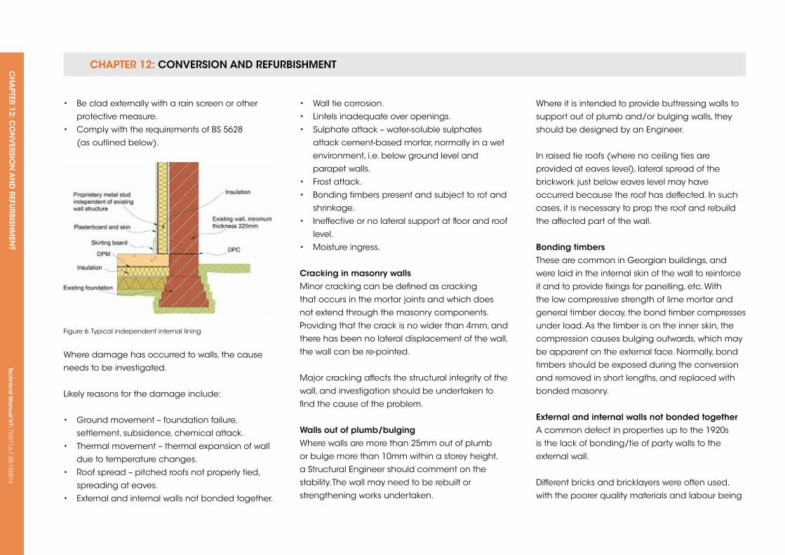
CHAPTER 12: CONVERSION AND REFURBISHMENTCH
APTER 12: C
ON
VERSIO
N A
ND
REFURBISH
MEN
TTe
ch
nic
al M
anu
al V
7: TS-011a-7.00-180814
• Be clad externally with a rain screen or other
protective measure.
• Comply with the requirements of BS 5628
(as outlined below).
• Wall tie corrosion.
• Lintels inadequate over openings.
• Sulphate attack – water-soluble sulphates
attack cement-based mortar, normally in a wet
environment, i.e. below ground level and
parapet walls.
• Frost attack.
• Bonding timbers present and subject to rot and
shrinkage.
• Ineffective or no lateral support at floor and roof
level.
• Moisture ingress.
Cracking in masonry wallsMinor cracking can be defined as cracking
that occurs in the mortar joints and which does
not extend through the masonry components.
Providing that the crack is no wider than 4mm, and
there has been no lateral displacement of the wall,
the wall can be re-pointed.
Major cracking affects the structural integrity of the
wall, and investigation should be undertaken to
find the cause of the problem.
Walls out of plumb/bulgingWhere walls are more than 25mm out of plumb
or bulge more than 10mm within a storey height,
a Structural Engineer should comment on the
stability. The wall may need to be rebuilt or
strengthening works undertaken.
Where it is intended to provide buttressing walls to
support out of plumb and/or bulging walls, they
should be designed by an Engineer.
In raised tie roofs (where no ceiling ties are
provided at eaves level), lateral spread of the
brickwork just below eaves level may have
occurred because the roof has deflected. In such
cases, it is necessary to prop the roof and rebuild
the affected part of the wall.
Bonding timbersThese are common in Georgian buildings, and
were laid in the internal skin of the wall to reinforce
it and to provide fixings for panelling, etc. With
the low compressive strength of lime mortar and
general timber decay, the bond timber compresses
under load. As the timber is on the inner skin, the
compression causes bulging outwards, which may
be apparent on the external face. Normally, bond
timbers should be exposed during the conversion
and removed in short lengths, and replaced with
bonded masonry.
external and internal walls not bonded togetherA common defect in properties up to the 1920s
is the lack of bonding/tie of party walls to the
external wall.
Different bricks and bricklayers were often used,
with the poorer quality materials and labour being
Figure 6: Typical independent internal lining
Where damage has occurred to walls, the cause
needs to be investigated.
Likely reasons for the damage include:
• Ground movement – foundation failure,
settlement, subsidence, chemical attack.
• Thermal movement – thermal expansion of wall
due to temperature changes.
• Roof spread – pitched roofs not properly tied,
spreading at eaves.
• External and internal walls not bonded together.
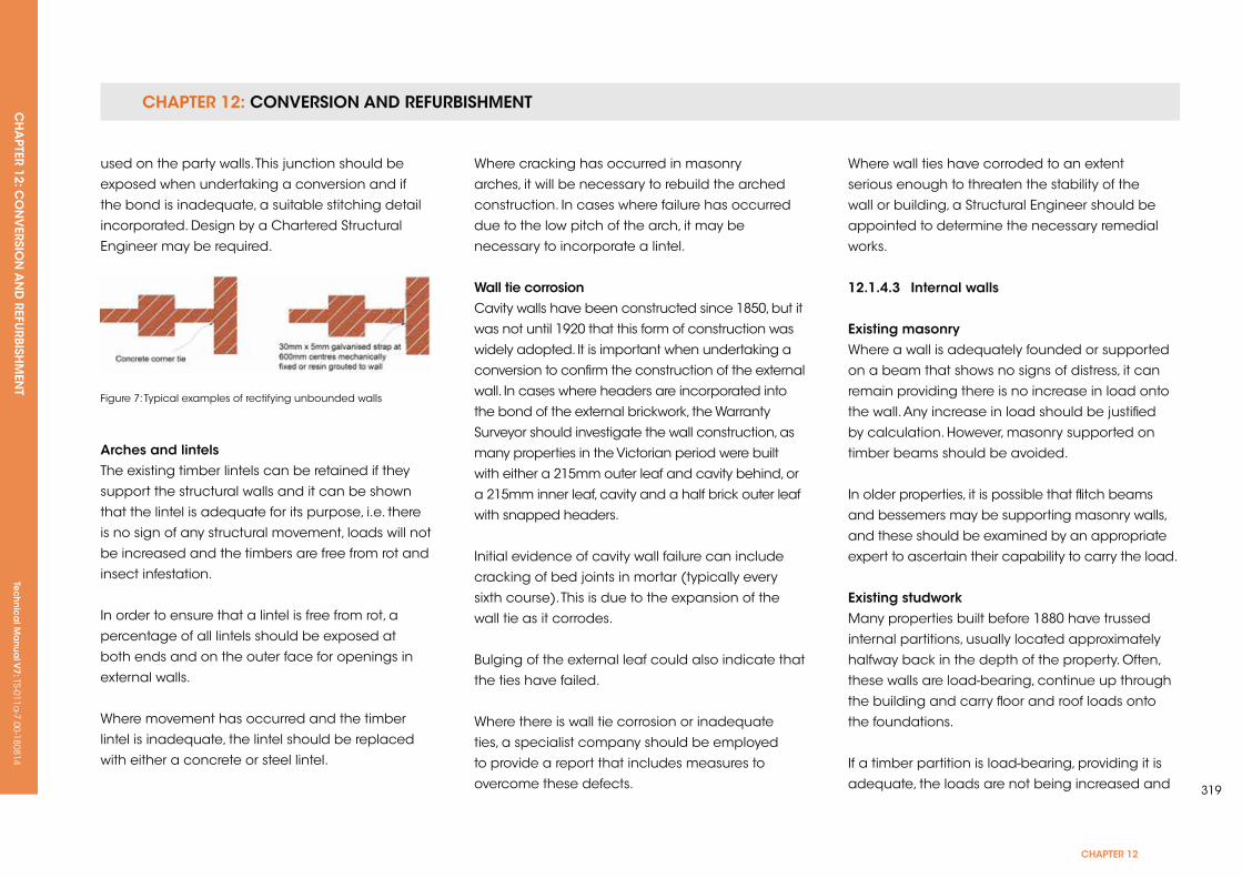
CHAPTER 12: CONVERSION AND REFURBISHMENTCH
APTER 12: C
ON
VERSIO
N A
ND
REFURBISH
MEN
T Te
ch
nic
al M
anu
al V
7: TS-011a-7.00-180814
CHAPTER 12
319
used on the party walls. This junction should be
exposed when undertaking a conversion and if
the bond is inadequate, a suitable stitching detail
incorporated. Design by a Chartered Structural
Engineer may be required.
Where cracking has occurred in masonry
arches, it will be necessary to rebuild the arched
construction. In cases where failure has occurred
due to the low pitch of the arch, it may be
necessary to incorporate a lintel.
Wall tie corrosionCavity walls have been constructed since 1850, but it
was not until 1920 that this form of construction was
widely adopted. It is important when undertaking a
conversion to confirm the construction of the external
wall. In cases where headers are incorporated into
the bond of the external brickwork, the Warranty
Surveyor should investigate the wall construction, as
many properties in the Victorian period were built
with either a 215mm outer leaf and cavity behind, or
a 215mm inner leaf, cavity and a half brick outer leaf
with snapped headers.
Initial evidence of cavity wall failure can include
cracking of bed joints in mortar (typically every
sixth course). This is due to the expansion of the
wall tie as it corrodes.
Bulging of the external leaf could also indicate that
the ties have failed.
Where there is wall tie corrosion or inadequate
ties, a specialist company should be employed
to provide a report that includes measures to
overcome these defects.
Where wall ties have corroded to an extent
serious enough to threaten the stability of the
wall or building, a Structural Engineer should be
appointed to determine the necessary remedial
works.
12.1.4.3 internal walls
existing masonryWhere a wall is adequately founded or supported
on a beam that shows no signs of distress, it can
remain providing there is no increase in load onto
the wall. Any increase in load should be justified
by calculation. However, masonry supported on
timber beams should be avoided.
In older properties, it is possible that flitch beams
and bessemers may be supporting masonry walls,
and these should be examined by an appropriate
expert to ascertain their capability to carry the load.
existing studworkMany properties built before 1880 have trussed
internal partitions, usually located approximately
halfway back in the depth of the property. Often,
these walls are load-bearing, continue up through
the building and carry floor and roof loads onto
the foundations.
If a timber partition is load-bearing, providing it is
adequate, the loads are not being increased and
Figure 7: Typical examples of rectifying unbounded walls
Arches and lintelsThe existing timber lintels can be retained if they
support the structural walls and it can be shown
that the lintel is adequate for its purpose, i.e. there
is no sign of any structural movement, loads will not
be increased and the timbers are free from rot and
insect infestation.
In order to ensure that a lintel is free from rot, a
percentage of all lintels should be exposed at
both ends and on the outer face for openings in
external walls.
Where movement has occurred and the timber
lintel is inadequate, the lintel should be replaced
with either a concrete or steel lintel.
CHAPTER 12: CONVERSION AND REFURBISHMENTCH
APTER 12: C
ON
VERSIO
N A
ND
REFURBISH
MEN
TTe
ch
nic
al M
anu
al V
7: TS-011a-7.00-180814
the timber is free from rot and insect infestation,
it can remain. Where there are defects, i.e. the
floor sags on the line of the partition and there
is distortion of door heads, then additional
strengthening works should be undertaken.
New door openings cut into an existing trussed
partition should be overseen by a qualified
Structural Engineer, as this can adversely affect the
triangulation of the truss.
12.1.4.4 Timber floors above ground levelExisting timber floor joists can be retained within
the building, providing they are adequate for their
purpose.
The following points should be considered:
• Joists are of sufficient size for the span.
• Load on the floor is not being increased.
• Joists have not been weakened by excessive
notching and/or drilling.
• Ends of joists are free from rot.
• All timbers to be treated for insect infestation
and wood rot.
• No masonry walls are built off timber joists.
• Appropriate strutting is provided.
Alterations to existing openingsWhere existing openings are to be filled with
masonry, the new work should be adequately
bonded to the existing and the weather resistance
of the wall maintained. However, if a party wall it
should comply with the requirements for sound
insulation.
12.1.4.5 Walls of special constructionIf it is intended to retain walls of special
construction, such as wattle and daub, Tudor,
mud walls (cob), etc., they should be altered so
as to form a non-structural element, e.g. by the
incorporation of an additional load-bearing wall or
framing to provide lateral support to the wall and
support all structural loads previously supported by
the wall. It will also be necessary to ensure that the
wall provides an adequate barrier to the passage
of rain water into the fabric or the inside of the
building.
unfortunately, due to the inherent risks and
planning conditions on these types of
developments, it must be noted that it may not be
possible to provide a Warranty.
12.1.4.6 interiorWhere the scheme involves converting a concrete
or steel-framed building into dwellings, the following
guidance is given.
An appraisal of the existing building should be
carried out by an experienced and qualified
Structural Engineer, taking into account the
proposals for the change of use. This will include:
• Condition of the structural frame, including
joints.
• Proposals to increase loadings on the structure
and foundations.
• Alterations to existing load paths.
• Alterations to stability systems.
• Changes in environmental exposure.
• Recommendations to cover additional reports
and testing by Specialists.
The floor loads on the building may decrease,
as they will now be for domestic use only where
previously they were, for example, offices.
A statement from a qualified Structural Engineer
confirming, where appropriate, that the existing
foundation design is acceptable for the new loads
subject to the building showing no signs of distress,
i.e. movement, cracking, etc., will be acceptable in
such circumstances.
Where the intention is to increase the load on the
existing structure, e.g. by the introduction of an
additional floor, then structural calculations should
be provided to prove the adequacy of the building
and foundations.
CHAPTER 12: CONVERSION AND REFURBISHMENTCH
APTER 12: C
ON
VERSIO
N A
ND
REFURBISH
MEN
T Te
ch
nic
al M
anu
al V
7: TS-011a-7.00-180814
CHAPTER 12
321
Concrete-framed buildingsWhere the building is of concrete construction,
additional reports are needed for:
• Carbonation
• Chlorination
The two major causes of corrosion in concrete
are carbonation, in association with inadequate
depth of cover to the reinforcement, and chlorine
penetration, due to the de-icing salts and
admixtures used to accelerate the setting and
hardening of concrete in temperatures at or below
freezing point.
Carbonation involves a reaction of carbon dioxide
in the air with the free lime present in the concrete.
Over a period of time, this reduces the pH level of
the concrete.
With a reduction in the alkalinity, and the presence
of both water and oxygen, corrosion of the
embedded steel will occur.
Visual surveys on concrete structures are a starting
point to gather information. However, care should
be taken, as although the concrete structure
may not show any obvious signs, corrosion of the
reinforcement may be occurring.
It is important that a second-stage survey
incorporates the following:
• Chemical tests on the concrete structure to
ascertain if corrosion of the steelwork is
occurring or likely to occur.
• Depth of carbonation can be assessed either
on-site or in the laboratory, and the depth of the
reinforcement measured. This allows areas of risk
to be identified.
• Chloride ion content can be determined by
analysis of a drilled dust sample taken from the
concrete.
Where concrete repairs are necessary, they should
be carried out by a Specialist Contractor.
High alumina cement concrete (HACC)Where HACC has been used in a building, and
the intentions are to keep the existing structure,
consideration should be given to:
• The structure being free from obvious signs of
deterioration.
• The building being weather tight.
• Structural calculations being provided to show
that the floors and roof can solely carry the
loads imposed on them.
Alkali silica reaction (Asr)The ASR occurs when the strongly alkaline cement
begins to dissolve susceptible sand and aggregate
within the concrete itself. The chemical reaction
creates a gel material that absorbs water, expands
and in turn creates tremendous pressures in the
pores of the concrete surface and subsequent
cracking. For a damaging reaction to occur, the
following need to be present in sufficient quantities:
• High alkali cement or a high cement content;
it may also arise from salt contamination during
batching/mixing.
• Reactive aggregate – siliceous materials such
as flint and quartz, as well as recycled
aggregates.
• Moisture, through exposure to rain or
condensation.
If any one of these factors is absent then the ASR
cannot take place. Once cracking occurs, the
structure can deteriorate further as water entering
the cracks generates reinforcement corrosion and
this, in conjunction with the freeze/thaw cycle, can
result in additional cracking and so on.
Affected concrete often exhibits surface cracking
in the pattern of a star, and heavily loaded sections
may exhibit cracks along the line of the main
reinforcement.
CHAPTER 12: CONVERSION AND REFURBISHMENTCH
APTER 12: C
ON
VERSIO
N A
ND
REFURBISH
MEN
TTe
ch
nic
al M
anu
al V
7: TS-011a-7.00-180814
Defects in structures attributable to the
performance of concrete are relatively rare in
the uk. Increased awareness of ASR, and the
publication of guidance on avoidance, have
reduced the risk of problems in new buildings to
very small proportions.
Consequently, on any refurbishment project
where the existing structure is concrete-frame,
the Warranty Surveyor will request copies of the
following to identify the presence or otherwise of
ASR:
• Desk studies undertaken to identify materials
used in the original construction.
• Core sampling and detailed chemical testing.
If ASR is identified, the following possible remedial
works will need to be assessed by the project’s
Design Engineer, and the details put to Warranty
Surveyors for consideration:
• Critical examination of the robustness of the
reinforcement.
• Measures to the amount of water available to
the structure – any weather proofing or
cladding should not impair the ability of the
structure to dry naturally.
• Limited strengthening of the structure.
• Partial or full demolition, followed by rebuilding.
Furthermore, any alterations to the weather proof
envelope will need to be considered to ensure
that the concrete elements are not exposed to
additional sources of moisture.
steel-framed buildingsIn addition to any structural reports, a visual
inspection of the steel frame should be carried out to
assess the extent of any corrosion of the framework.
Where corrosion is present, accurate
measurements can be made using an ultrasonic
gauge. Data collected can then compare the
thickness of steel sections against the original
steelwork drawings, British Standards and the
Historical Structural Steelwork Handbook to
ascertain if the structural frame is adequate for the
proposed loads.
exterior steelwork: should be inspected; where
corrosion is visible, the steel can be grit blasted,
cleaned and recoated.
Perimeter steelwork: in direct contact with
the outer leaf of the building can be prone
to corrosion, particularly in older properties. A
sign indicating that this has happened is the
displacement of the external masonry due to the
expansion of the steelwork caused by corrosion.
During the conversion process, the appropriate
repairs/replacement should be carried out.
interior steelwork: normally, corrosion of
unprotected steelwork within the interior of
a building is low, with only superficial rusting.
Providing that a visual inspection confirms this,
and the environment intends to remain dry, no
further treatment of the steel will be required.
Where the proposals involve the steelwork in a ‘wet’
environment, such as kitchens and bathrooms, it
should be adequately protected.
Bimetallic corrosionThis should be considered in the existing and
proposed structure.
Bimetallic corrosion occurs where two different
metals are in electrical contact and are bridged
by water or water containing other chemicals to
form an electrolyte. A current passes through the
solution from the base metal to the noble metal
and, as a consequence, the noble metal remains
protected and the base metal suffers increased
corrosion.
Where there is a possibility of this occurring, or if it
has already occurred, advice should be taken from
a Specialist on how to deal with it.
Cast iron, wrought iron and mild steel structuresMany older buildings that are converted into
dwellings, e.g. warehouses, cotton mills, etc., were
built using cast iron, wrought iron or mild steel.
CHAPTER 12: CONVERSION AND REFURBISHMENTCH
APTER 12: C
ON
VERSIO
N A
ND
REFURBISH
MEN
T Te
ch
nic
al M
anu
al V
7: TS-011a-7.00-180814
CHAPTER 12
323
When the intention is to keep the existing structural
elements, an appraisal of the existing building is
necessary.
In addition to this, the Engineer should comment
on the following:
• Determine the age of the building and the
materials used.
• Assess how its construction has fared.
• Justify the loadings by calculation.
• Identify areas where additional testing and/or
opening up is necessary.
If the proposed loads remain unchanged or
are reduced, as will probably be the case, and
it can be shown that the existing structure has
not suffered any deterioration due to corrosion or
deflection of structural members, etc., the building
may only require localised structural alterations.
Where the intention is to increase loads, carry out
major structural alterations or the existing building
is under-designed, a Structural Engineer should
comment on this and provide calculations to justify
the proposals.
12.1.4.7 filler joist floorsMany buildings of the late Victorian and Edwardian
periods were built with floors constructed of
clinker concrete supported by embedded iron
or steel joists. The concrete produced with clinker
aggregate was porous, and therefore provided
poor corrosive protection to the metal.
The clinker also contains particles of un-burnt
or partially burnt coke or coal, which contain
substantial proportions of sulphur. As the concrete
is porous, the sulphur oxidises to form sulphur
dioxide (SO2), and if moisture is present, this then
forms sulphuric acid (H2SO4). Where floors have
been subject to the weather for any length of time,
severe corrosion of the embedded iron or steelwork
is likely to have occurred.
When considering a conversion in a building with
filler joist floors, it is important to first investigate
whether the floors have been subject to damp
conditions and whether any significant corrosion
has taken place.
Particular attention should also be paid to ensuring
that the floor remains dry during the conversion,
and this could include providing a temporary
covering if removal of the existing roof is necessary.
12.1.4.8 Timber roofs
surveying roof timbersAll roof timbers should be surveyed by a Specialist,
and any necessary treatment carried out. Particular
attention should be given to rafter feet, wall plates
and valley timbers, as these often show signs of rot.
roof structureIt is essential that the roof structure has adequate
strength, stiffness and dimensional accuracy
appropriate for the new roof covering. All
strengthening work should be designed by a
Structural Engineer.
Common problems encountered include:
• Excessive spans of rafters, purlins, binder and
ceiling joists.
• Inadequate ties between rafters and ceiling ties.
• Insufficient number of collar ties at purlin level.
• Decay of rafter feet and valley beams.
• Settlement of purlin supports.
• Lateral spread of raised-tie roofs.
roof coveringsSystematic replacement of all roof coverings,
including associated support systems such as
battens, felt, flat roof decking, fascias, soffits and
flashings, should be carried out, unless it can be
shown that the existing roof covering is adequate.
Fixing of slates, tiles and the condition of existing
fixings, e.g. nails and clips, should be examined if
the intention is to keep the roof covering.
CHAPTER 12: CONVERSION AND REFURBISHMENTCH
APTER 12: C
ON
VERSIO
N A
ND
REFURBISH
MEN
TTe
ch
nic
al M
anu
al V
7: TS-011a-7.00-180814
A Specialist’s report (See 12.1.2) will be required to
confirm the adequacy of the existing roof covering
and to determine whether timber treatment is
required. Adequate ventilation should be provided
as appropriate.
Where it is intended to re-use existing roofing tiles or
slates, they should have a life span of at least 15 years.
In the case of replacement roof coverings where
no extra load is incurred, it may still be necessary
to strengthen the roof structure if the roof has
deflected.
12.1.4.9 Claddings
Weather resistance of walls and claddingExisting solid brick or stone walls are unlikely to
be acceptable as weather-resisting, although
consideration of the exposure category of the
building and porosity of the masonry will be given,
i.e. do existing non-gypsum-based internal linings
allow for greater insulation and evaporation than
gypsum plasters alone? It is anticipated that in all
buildings, at least one of the additional treatments
noted below will be required, and this must include
appropriate insulation.
However, all solid masonry wall situations will
require a Specialist’s report to identify the extent of
any necessary remedial treatment.
external treatmentsExisting claddings can be retained if it can be
shown that:
• The system is maintaining the integrity of the
building.
• It is adequately fixed and the expected life span
of the fixings, where appropriate, is in excess of
15 years.
• The cladding material is free from any defects.
• Adequate provision for movement has been
allowed.
If the above situations cannot be satisfied, a new
external cladding or render system will need to be
installed.
internal treatmentsAn alternative to preventing moisture penetration
by using externally applied claddings and renders
is to adopt internally applied methods.
Systems are available that are installed on
the inside of existing walls to prevent moisture
penetration reaching the internal accommodation.
These include:
• independent metal or timber framed systems: these should not be fixed to the existing
masonry walls, but fixed at the ‘head and
base’ to avoid direct contact. Ventilation should
be provided to avoid a build-up of
condensation between the masonry and the
inner lining system
• new internal walls: these would normally be
formed in blockwork, must be adequately
founded and, where necessary, tied to the
retained and new elements of structure
Control of damp penetrationMeasures should be taken to ensure that thermal
insulation in cavities does not encourage the
passage of damp from the ground or from the
exterior of the building to the inside of the building.
Thermal insulation of walls and claddingsVarious methods exist to upgrade the thermal
insulation of existing walls and floors. Regardless
of the methods adopted, it is essential that risks
associated with increased thermal insulation are
minimised, including:
CHAPTER 12: CONVERSION AND REFURBISHMENTCH
APTER 12: C
ON
VERSIO
N A
ND
REFURBISH
MEN
T Te
ch
nic
al M
anu
al V
7: TS-011a-7.00-180814
CHAPTER 12
325
• Surface condensation caused by improvements
to draught proofing of the building.
• Interstitial condensation caused by moisture-
laden air passing from the dwelling to within the
fabric of the structure and condensing on
cooler surfaces.• Increased risk of damp penetration caused by the filling of cavities with insulation.• Maintaining the robustness of the external and internal wall surfaces by the provision of adequate mechanical protection over insulation materials, e.g. externally applied insulation systems with render coat mechanical
protection.
• Avoidance of cold bridges around openings
and where structural elements extend through
the thickness of the building envelope.
• Repeating thermal bridging must be
considered, e.g. internal metal-framed walls
should be used in conjunction with thermally
insulated plaster board.
12.1.4.10 render application finishesPlaster for conversions/refurbishment
Where the condition and bond of the existing
plaster can be shown to be adequate, it can
remain, with the exception of the following:
• Where rising damp is present.
• Where a chemical DPC is installed.
• At the junction of external walls and party walls
to see if they are properly bonded.
• Above openings to examine the make-up and
condition of lintels.
• Where there is a possibility that bond timbers
may have decayed.
• Where the wall is solid and the plaster is
gypsum-based.
Where a chemically injected DPC is installed, it is
necessary to remove the plaster one meter above
the DPC level or 600mm above any apparent salt
line/dampness, whichever is higher.
Re-plastering work should be delayed as long as
possible in order to encourage rapid evaporation
of residual moisture, and the building should be
well ventilated during the drying period.
Plastering work must comply with an independent
third-party, and the chemical DPC must meet the
manufacturer’s recommendations. Recommended
plasters usually incorporate adhesives to increase
resistance to the passage of hygroscopic salts from
the wall into the plaster. They should not, however,
act as a vapour barrier. Gypsum plaster should not
be used in conjunction with chemically injected
DPC.
The plaster should not bridge the DPC or be in
contact with the ground floor slab.
Final redecoration should not be carried out until
residual moisture has disappeared. Matt emulsion
paint is recommended for use during this period.
Internally drilled holes concealed by skirting
boards, etc. should not be plugged. Other visible
holes and external holes should be plugged.
rendering for conversion/refurbishmentWhere the condition and bond of the existing
render can be shown to be adequate, it can
remain, subject to the following exceptions:
• If the render bridges the DPC.
• Above door and window openings where it is
necessary to examine the type and condition of
the lintels.
• Where there are signs of structural movement in
the building, and further investigation is
required.
Tec
hn
ica
l Ma
nua
l V6: TS-011a
-6.00-010413Te
ch
nic
al M
anu
al V
7: TS-011a-7.00-180814
FUNCTIONAL REQUIREMENTS
12.2 neW eLeMenTs ConneCTing To exisTing sTruCTures
Workmanshipi. All workmanship must be within the tolerances defined in Chapter 1
of this Manual.
ii. All work is to be carried out by a technically competent person in
a workmanlike manner.
Materialsi. All materials should be stored correctly in a manner that will not cause
damage or deterioration of the product.
ii. All materials, products and building systems shall be appropriate and
suitable for their intended purpose.
iii. The structure shall, unless specifically agreed otherwise with the
Warranty provider, have a life of not less than 60 years. Individual
components and assemblies, not integral to the structure, may have a
lesser durability, but not in any circumstances less than 15 years.
Designi. The design and specifications shall provide a clear indication of the
design intent and demonstrate a satisfactory level of performance.
ii. There should be a Party Wall Agreement in accordance with the Party
Wall Act (please note that this requirement will be relevant where the
applicant is not the owner of the adjoining property).
iii. The separating wall between the new and existing building must meet
the relevant requirements of the Building Regulations.
iv. The existing foundations and wall structure must be suitable to support
any proposed increased loading resulting from the construction of the
new dwelling.
v. The junction of the new walls to the existing walls must ensure that
dampness cannot track back into the new home or the existing home.
vi. An effective Damp Proof Course should be present in the existing wall,
linked to the new Damp Proof Course and damp proof membrane of
the new home.
vii. At the junction of the existing and new structures, detailing should
allow for differential movement without cracking. Any settlement
should be limited to 2mm–3mm, which would not normally adversely
affect the roof covering.
viii. The materials used for construction must meet the relevant
Building Regulations, British Standards, Eurocodes and other statutory
requirements.
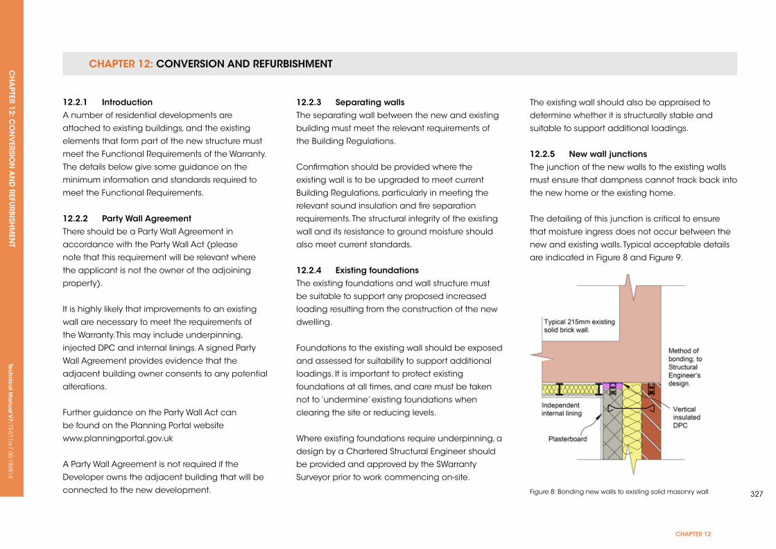
CHAPTER 12: CONVERSION AND REFURBISHMENTCH
APTER 12: C
ON
VERSIO
N A
ND
REFURBISH
MEN
T Te
ch
nic
al M
anu
al V
7: TS-011a-7.00-180814
CHAPTER 12
327
12.2.1 introductionA number of residential developments are
attached to existing buildings, and the existing
elements that form part of the new structure must
meet the Functional Requirements of the Warranty.
The details below give some guidance on the
minimum information and standards required to
meet the Functional Requirements.
12.2.2 Party Wall AgreementThere should be a Party Wall Agreement in
accordance with the Party Wall Act (please
note that this requirement will be relevant where
the applicant is not the owner of the adjoining
property).
It is highly likely that improvements to an existing
wall are necessary to meet the requirements of
the Warranty. This may include underpinning,
injected DPC and internal linings. A signed Party
Wall Agreement provides evidence that the
adjacent building owner consents to any potential
alterations.
Further guidance on the Party Wall Act can
be found on the Planning Portal website
www.planningportal.gov.uk
A Party Wall Agreement is not required if the
Developer owns the adjacent building that will be
connected to the new development.
12.2.3 separating wallsThe separating wall between the new and existing
building must meet the relevant requirements of
the Building Regulations.
Confirmation should be provided where the
existing wall is to be upgraded to meet current
Building Regulations, particularly in meeting the
relevant sound insulation and fire separation
requirements. The structural integrity of the existing
wall and its resistance to ground moisture should
also meet current standards.
12.2.4 existing foundationsThe existing foundations and wall structure must
be suitable to support any proposed increased
loading resulting from the construction of the new
dwelling.
Foundations to the existing wall should be exposed
and assessed for suitability to support additional
loadings. It is important to protect existing
foundations at all times, and care must be taken
not to ‘undermine’ existing foundations when
clearing the site or reducing levels.
Where existing foundations require underpinning, a
design by a Chartered Structural Engineer should
be provided and approved by the SWarranty
Surveyor prior to work commencing on-site.
The existing wall should also be appraised to
determine whether it is structurally stable and
suitable to support additional loadings.
12.2.5 new wall junctions The junction of the new walls to the existing walls
must ensure that dampness cannot track back into
the new home or the existing home.
The detailing of this junction is critical to ensure
that moisture ingress does not occur between the
new and existing walls. Typical acceptable details
are indicated in Figure 8 and Figure 9.
Figure 8: Bonding new walls to existing solid masonry wall

CHAPTER 12: CONVERSION AND REFURBISHMENTCH
APTER 12: C
ON
VERSIO
N A
ND
REFURBISH
MEN
TTe
ch
nic
al M
anu
al V
7: TS-011a-7.00-180814
Figure 9: Bonding new walls to existing cavity masonry wall
12.2.6 Damp Proof Course (DPC)An effective DPC should be present in the existing
wall, linked to the new DPC and Damp Proof
Membrane (DPM) of the new home.
Acceptable existing DPCs are considered as:
• A continuous felt or proprietary DPC material
• A chemically injected DPC supported by an
insurance-backed guarantee
• A slate DPC is considered acceptable if the
existing wall incorporates an independent wall
lining system to the inner face of the new dwelling
The new DPC should lap the existing DPC by at
least 100mm.
12.2.7 existing and new structure junctionsAt the junction of the existing and new structures,
detailing should allow for differential movement
without cracking. Any settlement should be limited
to 2mm–3mm, which would not normally adversely
affect the roof covering.
Typical details of bonding new walls to existing are
indicated in Figure 8 and Figure 9.
In order to prevent excessive differential movement,
the new dwelling should have the same
foundation type as the existing dwelling. Where the
foundation types are different, e.g. new dwelling
pile and beam, existing dwelling traditional strip
foundation, the new dwelling should be completely
independent of the existing dwelling.
CH
APTER 13: SU
STAIN
ABILITY
Tec
hn
ica
l Ma
nua
l V7: TS-011a
-7.00-180814
CHAPTER 13
329
CHAPTer 13: susTAinABiLiTy
This chapter has been removed.

Tec
hn
ica
l Ma
nua
l V6: TS-011a
-6.00-010413Te
ch
nic
al M
anu
al V
7: TS-011a-7.00-180814
noTes
Tec
hn
ica
l Ma
nua
l V6: TS-011a
-6.00-010413Te
ch
nic
al M
anu
al V
7: TS-011a-7.00-180814
331
noTes
Tec
hn
ica
l Ma
nua
l V6: TS-011a
-6.00-010413Te
ch
nic
al M
anu
al V
7: TS-011a-7.00-180814
noTes


T 0845 054 0505 F 0845 054 0501 E [email protected]
MD Insurance Services Ltd. is the scheme administrator for LABC Warranty and is authorised and regulated by the Financial Conduct Authority. Registered in England No: 3642459.