Embed Size (px)
Citation preview
STRUCTURES AND LAND RIG MOBILIZATION ST-1
Copyright © 2015IADC Drilling Manual
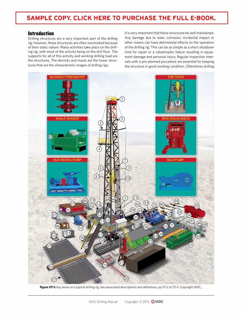
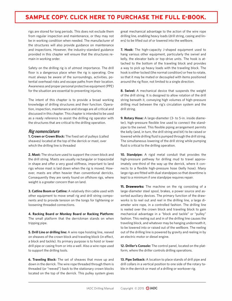
IntroductionDrilling structures are a very important part of the drilling rig; however, these structures are often overlooked because of their static nature. Many activities take place on the drill-ing rig, with most of the activity being on the drill floor. The supports for all of this activity and working drilling load are the structures. The derricks and masts are the tower struc-tures that are the characteristic images of drilling rigs.
It is very important that these structures be well maintained. Any damage due to wear, corrosion, incidental impact or other means can have detrimental effects on the operation of the drilling rig. This can be as simple as a short shutdown time for repair or a catastrophic failure resulting in equip-ment damage and personal injury. Regular inspection inter-vals with a pre-planned procedure are essential for keeping the structure in good working condition. Oftentimes drilling
Figure ST-1: Key areas on a typical drilling rig. See associated descriptions and definitions, pp ST-2 to ST-5. Copyright IADC..
ST-2 STRUCTURES AND LAND RIG MOBILIZATION
Copyright © 2015IADC Drilling Manual
rigs are stored for long periods. This does not exclude them from regular inspection and maintenance, or they may not be in working condition when needed. The manufacturer of the structures will also provide guidance on maintenance and inspections. However, the industry-standard guidance provided in this chapter will ensure that the structures re-main in working order.
Safety on the drilling rig is of utmost importance. The drill floor is a dangerous place when the rig is operating. One must always be aware of the surroundings, activities, po-tential overhead risks and escape paths from their location. Awareness and proper personal protective equipment (PPE) for the situation are essential to preventing injuries.
The intent of this chapter is to provide a broad working knowledge of drilling structures and their function. Opera-tion, inspection, maintenance and storage are all critical and discussed in this chapter. This chapter is intended to be used as a ready reference to assist the drilling rig operator with the structures that are critical to the drilling operation.
Rig nomenclature1. Crown or Crown Block: The fixed set of pulleys (called sheaves) located at the top of the derrick or mast, over which the drilling line is threaded
2. Mast: The structure used to support the crown block and the drill string. Masts are usually rectangular or trapezoidal in shape and offer a very good stiffness, important to land rigs whose mast is laid down when the rig is moved. How-ever, masts are often heavier than conventional derricks. Consequently they are rarely found on offshore rigs, where weight is a greater concern than on land.
3. Catline Boom or Catline: A relatively thin cable used with other equipment to move small rig and drill string compo-nents and to provide tension on the tongs for tightening or loosening threaded connections.
4. Racking Board or Monkey Board or Racking Platform: The small platform that the derrickman stands on when tripping pipe.
5. Drill Line or drilling line: A wire rope hoisting line, reeved on sheaves of the crown block and traveling block (in effect, a block and tackle). Its primary purpose is to hoist or lower drill pipe or casing from or into a well. Also a wire rope used to support the drilling tools.
6. Traveling Block: The set of sheaves that move up and down in the derrick. The wire rope threaded through them is threaded (or “reeved”) back to the stationary crown blocks located on the top of the derrick. This pulley system gives
great mechanical advantage to the action of the wire rope drilling line, enabling heavy loads (drill string, casing and lin-ers) to be lifted out of or lowered into the wellbore.
7. Hook: The high-capacity J-shaped equipment used to hang various other equipment, particularly the swivel and kelly, the elevator bails or top-drive units. The hook is at-tached to the bottom of the traveling block and provides a way to pick up heavy loads with the traveling block. The hook is either locked (the normal condition) or free to rotate, so that it may be mated or decoupled with items positioned around the rig floor, not limited to a single direction.
8. Swivel: A mechanical device that suspends the weight of the drill string. It is designed to allow rotation of the drill string beneath it, conveying high volumes of high-pressure drilling mud between the rig’s circulation system and the drill string.
9. Rotary Hose: A large-diameter (3- to 5-in. inside diame-ter), high-pressure flexible line used to connect the stand-pipe to the swivel. This flexible piping arrangement permits the kelly (and, in turn, the drill string and bit) to be raised or lowered while drilling fluid is pumped through the drill string. The simultaneous lowering of the drill string while pumping fluid is critical to the drilling operation.
10. Standpipe: A rigid metal conduit that provides the high-pressure pathway for drilling mud to travel approx-imately one-third of the way up the derrick, where it con-nects to a flexible high-pressure hose (kelly hose). Many large rigs are fitted with dual standpipes so that downtime is kept to a minimum if one standpipe requires repair.
11. Drawworks: The machine on the rig consisting of a large-diameter steel spool, brakes, a power source and as-sorted auxiliary devices. The primary function of the draw-works is to reel out and reel in the drilling line, a large di-ameter wire rope, in a controlled fashion. The drilling line is reeled over the crown block and traveling block to gain mechanical advantage in a “block and tackle” or “pulley” fashion. This reeling out and in of the drilling line causes the traveling block, and whatever may be hanging underneath it, to be lowered into or raised out of the wellbore. The reeling out of the drilling line is powered by gravity and reeling in by an electric motor or diesel engine.
12. Driller’s Console: The control panel, located on the plat-form, where the driller controls drilling operations.
13. Pipe Setback: A location to place stands of drill pipe and drill collars in a vertical position to one side of the rotary ta-ble in the derrick or mast of a drilling or workover rig.
STRUCTURES AND LAND RIG MOBILIZATION ST-3
Copyright © 2015IADC Drilling Manual
14. Drill Floor: This is the heart of any drilling rig. It is the area where the drill string is drilled into the eary. Tradition-ally where joints of pipe are assembled, as well as the bot-tomhole assembly (BHA), drill bit and other tools. This is the primary work location for roughnecks and the driller. The drill floor is located directly beneath the derrick or mast.
15. Rotary Table: The revolving or spinning section of the drill floor that provides power to turn the drill string in a clockwise direction (as viewed from above). The rotary mo-tion and power are transmitted through the kelly bushing and the kelly to the drill string. When the drill string is rotat-ing, the drilling crew commonly describes the operation as simply, “rotating to the right,” “turning to the right” or “rotat-ing on bottom.” Almost all rigs today have a rotary table, ei-ther as primary or backup system for rotating the drill string. Top-drive technology, which allows continuous rotation of the drill string, has replaced the rotary table in certain oper-ations. A few rigs are being built today with top-wash-drive systems only, and lack the traditional kelly system.
16. Substructure: The foundation structure on which the derrick, rotary table, draw-works and other drilling equip-ment are supported.
17. Blowout Preventer Stack: A set of two or more BOPs used to ensure pressure control of a well. A typical stack might consist of one to six ram-type preventers and, op-tionally, one or two annular-type preventers. A typical stack configuration has the ram preventers on the bottom and the annular preventers at the top. The configuration of the stack preventers is optimized to provide maximum pressure integ-rity, safety and flexibility in the event of a well-control inci-dent. For example, in a multiple ram configuration, one set of rams might be fitted to close on 5-in. diameter drill pipe, another set configured for 4 ½-in. drill pipe, a third fitted with blind rams to close on the open hole and a fourth fitted with a shear ram that can cut and hang-off the drill pipe as a last resort. It is common to have an annular preventer or two on the top of the stack since annulars can be closed over a wide range of tubular sizes and the open hole, but are typi-cally not rated for pressures as high as ram preventers. The BOP stack also includes various spools, adapters and pip-ing outlets to permit the circulation of wellbore fluids under pressure in the event of a well-control incident.
18. Dog House or Driller’s Cabin: The steel-sided room ad-jacent to the rig floor, usually having an access door close to the driller’s controls. This general-purpose shelter is a com-bination tool shed, office, communications center, coffee room, lunchroom and general meeting place for the driller and his crew. It is at the same elevation as the rig floor, usu-ally cantilevered out from the main substructure supporting the rig.
19. Choke Manifold: A set of high-pressure valves and as-sociated piping that usually includes at least two adjustable chokes, arranged such that one adjustable choke may be isolated and taken out of service for repair and refurbish-ment while well flow is directed through the other one.
20. Gas Flare or Flare Stack: A gas combustion device used in industrial plants such as petroleum refineries, chemical plants, natural gas processing plants as well as at oil or gas production sites having oil wells, gas wells, offshore oil and gas rigs, and landfills.
21. Mud Gas Separator or Gas Buster or Poor Boy Degas-ser: A device that captures and separates a large volume of free gas within the drilling fluid. If there is a “kick” situa-tion, this vessel separates the mud and the gas by allowing it to flow over baffle plates. The gas then is forced to flow through a line and vent it to a flare. A “KICK” situation hap-pens when the annular hydrostatic pressure in a drilling well temporarily (and usually relatively suddenly) falls below that of the formation, or pore, pressure in a permeable section downhole and before control of the situation is lost.
22. Shale Shaker: The primary and probably most important device on the rig for removing drilled solids from the mud. This vibrating sieve is simple in concept, but a bit more com-plicated to use efficiently. A wire-cloth screen vibrates while the drilling fluid flows on top of it. The liquid phase of the mud and solids smaller than the wire mesh pass through the screen, while larger solids are retained on the screen and eventually fall off the back of the device and are discarded. Obviously, smaller openings in the screen clean more solids from the whole mud, but there is a corresponding decrease in flow rate per unit area of wire cloth. Hence, the drill-ing crew should seek to run the screens (as the wire cloth is called) as fine as possible without dumping whole mud off the back of the shaker. Where it was once common for drilling rigs to have only one or two shale shakers, modern high-efficiency rigs are often fitted with four or more shak-ers, thus giving more area of wire cloth to use and giving the crew the flexibility to run increasingly fine screens.
23. Degasser: A device that removes air or gases (methane, H2S, CO2 and others) from drilling liquids. There are two generic types that work by both expanding the size of the gas bubbles entrained in the mud (by pulling a vacuum on the mud) and by increasing the surface area available to the mud so that bubbles escape (through the use of various cas-cading baffle plates). If the gas content in the mud is high, a mud gas separator or “poor boy degasser” is used, because it has a higher capacity than standard degassers and routes the evolved gases away from the rig to a flaring area com-plete with an ignition source.