Embed Size (px)
Citation preview

28
INTRODUCTION
2.1 ELECTRIC CURRENT
2.2 THE VOLTAGE
2.3 ELECTRIC POWER
2.4 OHM'S LAW
2.5 SERIES AND PARALLELCOMBINATION OF RESISTORS
2.6 COMBINATION OF CAPACITORS
2.7 KIRCHOFF'S LAWS
2.8 VOLTAGE SOURCES
2.9 CURRENT SOURCES
2.10 DIRECT CURRENT ANDALTERNATING CURRENT
2.11 FREQUENCY, TIME PERIOD ANDPHASE ANGLE
2.12 AVERAGE AND RMS VALUES OF AC
2.13 CONCEPT OF IMPEDANCE
ELECTRICALFUNDAMENTALS
2
+ -
Fig 2.1 Simple electric circuit
INTRODUCTION
We know that electronics has become an integralpart of our life, through its vast range of applications.In the forthcoming chapters we will go through thebasic concepts of semiconductors, electronicdevices like diodes, transistors and other specialdevices, basic circuits of rectifiers, amplifiers andoscillators, fundamentals of digital electronics andmeasuring devices. Before that, let us go throughthe basic concepts of electricity, which is the sourceof energy that makes all electronic devices work.To begin with we shall look into what electriccurrent, voltage and power are, how electric currentis maintained through a conductor and how theelectric current varies according to the change inpotential difference. We shall also discuss theresistors and capacitors and the effect of series andparallel combinations of them. Further on, we willsee how to find the voltage across and the currentthrough different components in electrical circuitswith the help of Ohm's law and Kirchoff's law.
2.1. ELECTRIC CURRENT
Can you say, what actually happens when you pressthe switch of a torch light? The basic arrangementinside a torch is as shown in fig. 2.1. When theswitch 'S' is closed (switch pressed), electric currentsp
ecim
en

29
flows through the circuit. The flow of electric current makes the bulb glow. The direction ofelectric current is from positive terminal of the battery to the negative terminal of the battery.
Electric current flows from a higher potential point to a lower potential point. In case ofbattery, positive terminal is considered as at a higher potential compared to negative terminal.
The electric current or electric current intensity is defined as the rate of flow of electric charges.If q is the amount of charge that crosses any section of a conductor, in a time interval t, thenthe current 'I' is given by
I = qt
The unit of electric current is Ampere (A). A current of one ampere equals a flow of 1coulomb of charge per second. Ammeter is the instrument used for measuring electric current.
2.2. THE VOLTAGE
The voltage between two points is the work done (energy required) to move a unit positivecharge from one point to the other. It is also called as potential difference or electromotiveforce (emf).
V = WQ
where
V - potential difference or voltage in volts
W - energy spent in joules
Q - charge in coulombs
One volt is defined as the potential difference between two points in an electric circuit suchthat one joule of work must be done to move a charge of one coulomb between the points.Thus if an electric power line has a voltage of 220V, it follows that 220 J of work has to bedone to transfer each coulomb of electric charge through any apparatus connected betweenthe two wires.
1 Volt = 1 Joule/coulomb or 1V = 1 J/C. Voltmeter is the instrument used for measuringvoltage.
2.3. ELECTRIC POWER
Electric power is the time rate of doing work for moving charges from one point to another. Itis represented by the symbol 'P' and the unit of power is 'watt'. 'Watt' is practically defined asthe rate at which work is being done in a circuit in which a current of 1 ampere is flowing whenthe voltage applied is 1 volt.
spec
imen

30
The electric power consumed by aresistor is determined by the voltageacross it multiplied by the current flowingthrough it.
Power = Voltage Current
P = V I or P = VI
2.4. OHM'S LAW
We have seen that when potentialdifference is more, the current increases.It can be said that at constanttemperature, the potential differenceacross a conductor is directlyproportional to the electric currentthrough it.
Ohm's law can be written as V I atconstant temperature
V/I = Constant.
This constant of proportionality is termedas the resistance of the conductor. ItsSI unit is ohm ( ).
Those conductors which obey Ohm'slaw are called ohmic conductors.Examples for non-ohmic conductors aresemiconductors.
2.5. SERIES AND PARALLELCOMBINATION OF RESISTORS
Suppose for a certain circuit we requirea 200 resistor, and for some othercircuit we need a 50 resistor. But wehave only 100 resistors with us. Howcan we solve this problem?
It is possible to get these values bycombining the available resistors.
Activity 1
Assemble two circuits as shown in fig 2.2 andfig 2.3.
Fig 2.2 Same potentials applied at both the ends
What do you observe ? When the switches are closed, which bulb
glow and which does not? Think why these circuits behave
differently. Justify your observation
The bulb in the fig 2.2 does not glow sincethere is no potential difference between thepoints P and Q. In the fig 2.3 potential appliedat the terminals of bulb (points M and N) aredifferent. So the current flows through the bulband it glows. Thus we can conclude thatelectric current can be established through aconductor only if there is a potential differenceacross its ends. Now if the potential at 'M' isincreased, the bulb glows more and morebrightly due to higher current flow. Try to dothat.
Fig 2.3 Unequal potentials applied at the ends
spec
imen

31
The two ways of combining resistors are1. Series Combination2. Parallel Combination
Series Combination
Two or more resistors are said to be connected in series when they are connected in such away that the same current flows through all those resistors. Consider three resistors R1, R2and R3 connected in series and a voltage of ‘V’ volts is applied across it as in fig.2.4
Fig 2.4 Series combination of resistors
In this circuit the current through each resistor will be the same but the potential differenceacross each is different. It can be obtained using Ohm’s law.
Potential difference across R1, V1 = IR1
Potential difference across R2, V2 = IR2
Potential difference across R3, V3 = IR3
If ‘V’ is the effective potential drop and ‘R’ the effective resistance, then the effective potentialdifference across the combination is
V = IR
Total voltage across the combination is equal to the sum of the voltages across each resistor.
V = V1 + V2 + V3
Substituting the values of voltage
IR = IR1 + IR2 + IR3
Eliminating I from all the terms, we get
R = R1 + R2 + R3
Thus the effective resistance of the series combination of a number of resistors is equal to thesum of the resistances of individual resistors.
spec
imen

32
Parallel CombinationA number of resistors are said to be connectedin parallel when they are connected in such away that the same voltage appears across eachof those resistors. Consider three resistors R1,R2 and R3 are connected in parallel across apotential difference of V as in fig 2.5.Here, since all the resistors are connected acrossthe same terminals, the potential differencesacross all of the resistors are equal. But thecurrent will be different in each resistor and isgiven by Ohm’s law.
Current through R1, I1 = 1
VR
Current through R2, I2 = 2
VR
Current through R3, I3 = 3
VR
The total current through the combination is I = VR , where ‘R’ is the effective resistance of this
circuit.
The total current through the combination = the sum of the currents through each of theresistors
I = I1 + I2 + I3
Substituting the values of currents, we get
VR =
1
VR +
2
VR +
3
VR
Eliminating V from all the terms we get
1R =
1 2 3
1 1 1R R R
Thus in parallel combination the reciprocal of the effective resistance is equal to the sum of thereciprocals of individual resistances. The effective resistance in a parallel combination will besmaller than the value of the smallest resistance.
Fig 2.5 Parallel combination of resistors
spec
imen

33
When only two resistors of values R1 and R2 are connected in parallel, the effective resistance
of the combination is 1 2
1 2
R RRR R
Check your progressFind the total current flowing through the circuit in fig 2.6 and thecurrent through each of the resistors.
Solution
The resistors each of value 300 ohms are in parallel.
Effective resistance can be obtained as follows.
1R =
1300 +
1300 +
1300
R = 300
3
= 100 ohmsTotal current in the circuit.
=VR =
100100 = 1 ampere
Since R1 = R2 = R3 ,
Fig 2.6
spec
imen

34
The current through each of the resistors= Total current/ No. of resistors
= 13 ampere
From the above problem it can be notedthat if ‘n’ resistors each of value R ohmsare connected in parallel the effectiveresistance of the combination, Reff is
Reff = Rn
When two 100 ohm resistors areconnected in series we get a circuit resistance of 200 ohms because in series combination,Reffective = R1+ R2. For getting a 50 ohm effective resistance we have to combine two 100 ohmresistors in parallel since for parallel combination, 1/Reffective =1/R1 + 1/R2. Hence it is clearthat when resistors are connected in series, the effective circuit resistance increases and whenconnected in parallel, the effective circuit resistance decreases.
2.6 COMBINATION OF CAPACITORS
Capacitors can also be connected in series and in parallel.
Activity 2Now try to solve the problem stated in thebeginning of the section 2.5 (To get effectiveresistances of 200 and 50 using 100resistors). Draw the circuits required. What happens to the effective resistance
of the circuit when more resistors areaddeda) in series and b) in parallel
Fig 2.7 Series combination of capacitors
spec
imen

35
Capacitors in series :
Consider three capacitors of capacitances C1, C2 and C3 connected in series across a potentialdifference of ‘V’ volts. Here the same charge is stored in all the three capacitors. But thevoltage across each will be different. The total voltage across the circuit is equal to the sum ofvoltages across individual capacitors.
So V = V1+ V2+ V3 ___________ (1)
If the effective capacitance of the circuit is ‘C’ and since
Voltage = Charge/Capacitanceequation (1) becomes
qC =
1
qC +
2
qC +
3
qC
Eliminating ‘q’ from all the terms
1C =
1 2 3
1 1 1C C C
If there are only two capacitors connected in series
1C =
1 2
1 1C C or C =
1 2
1 2
C CC C
Capacitors in parallelIf three capacitors C1, C2 and C3 areconnected in parallel across a batteryof V volts, the potential differenceacross each capacitor will be the same.ie ,V volts. But the charge acquired byeach capacitor will be different.
If q1, q2 and q3 are the charges acquiredby C1, C2 and C3 respectively,the total charge drawn from the battery.
q = q1 + q2 + q3
If ‘C’ is the effective capacitance of thecombination .
CV = C1V + C2V + C3 VOR
Fig 2.8 Parallel combination of capacitors
spec
imen
36
C = C1 + C2 + C3
So the effective capacitance of a number of capacitors connected in parallel is equal to thesum of individual capacitances.
In series combination the effective capacitance is smaller than the smallest in the combinationwhile in parallel connection the effective capacitance is larger than the largest in the combination.
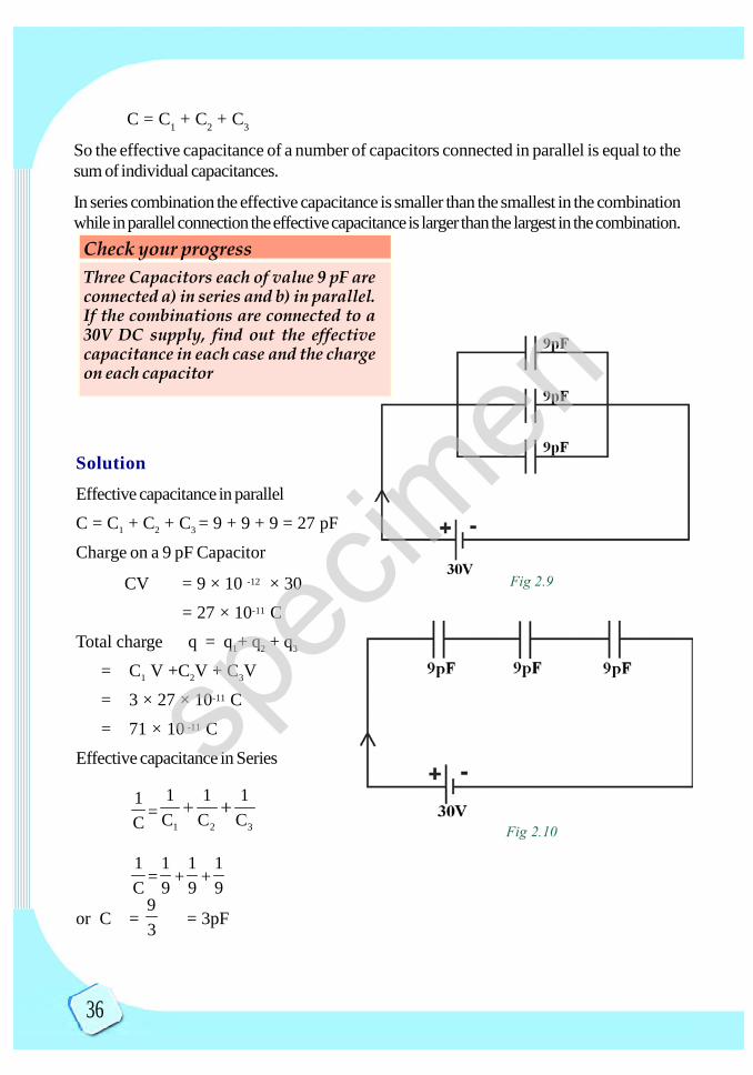
SolutionEffective capacitance in parallelC = C1 + C2 + C3 = 9 + 9 + 9 = 27 pF
Charge on a 9 pF Capacitor
CV = 9 × 10 -12 × 30= 27 × 10-11 C
Total charge q = q1+ q2 + q3
= C1 V +C2V + C3V= 3 × 27 × 10-11 C= 71 × 10 -11 C
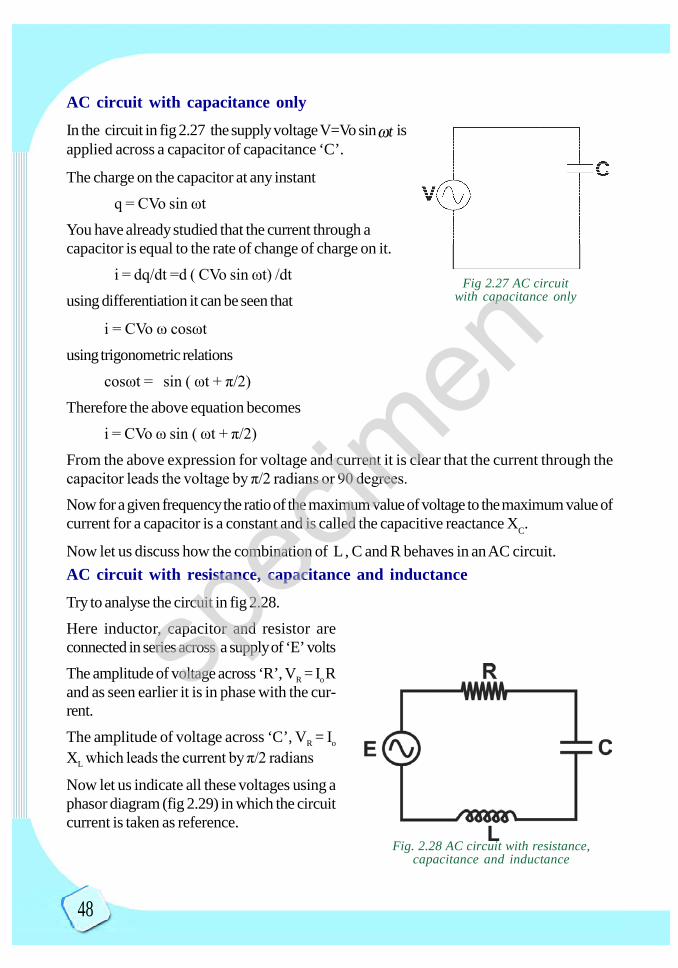
Effective capacitance in Series
1C =
1 2 3
1 1 1C C C
1C =
19 +
19 +
19
or C = 93 = 3pF
Check your progressThree Capacitors each of value 9 pF areconnected a) in series and b) in parallel.If the combinations are connected to a30V DC supply, find out the effectivecapacitance in each case and the chargeon each capacitor
Fig 2.10
Fig 2.9
spec
imen

37
In series combination, the charge on each capacitor will be the same
q = CV= 3 ×10 12 ×30
= 9 × 10 11C
2.7 KIRCHHOFF’S LAWS
Analyze the circuit given in fig 2.11
The above circuit cannot be reduced to asimple parallel or series combination as theresistors are neither in series nor in parallelwith each other. So such circuits cannotbe solved simply using Ohm's law. GustavRobert Kirchhoff proposed two generalrules for solving such networks.Kirchhoff’s Current law (KCL)In the words of Kirchhoff at any junction of several circuit elements, the sum of currentsentering a junction must be equal to the sum of currents leaving the junction. Considering thecircuit given in fig 2.11
For the junction A, I = I1 + I2
For the junction B, I1 = I3 + I4
For the junction C, I3 + I2 = I5
For the junction D, I4 + I5 = I
If the current entering a junction is taken as positive andcurrent leaving the junction as negative then Kirchhoff’scurrent law can be stated as “The algebraic sum of currentsmeeting a junction is zero’’.
Consider the diagram shown in figure 2.12 in which thecurrent I1 and I2 are entering the junction ‘O’ and thecurrents I3, I4, and I5 are leaving the junction.
Using Kirchhoff’s current law (KCL)
I1+ I2 – I3-I4-I5 = 0Kirchhoff’s Voltage law (KVL)Kirchhoff’s voltage law can be stated as "The algebraicsum of change in potential around any closed loop must be zero''.
Fig 2.11 Demonstration of Kirchhoff ’s law
Fig 2.12 Demonstration of KCL
spec
imen

38
Illustration
Consider the following circuit. Sign convention is very important while applying KVL. Thefollowing illustration will help you to understand it.
Let us take the loop ABCDA and assignanticlockwise direction for the tour startingfrom the point A.
1. As we move through the cell of emfE1, direction is from -ve to +ve, soE1 is taken as positive.
2. The direction of tour and the direc-tion of current are the same in thecase of R1 hence the potential dif-ference across R1 is taken as nega-tive i.e., -I1R1.
3. As we go through the cell of emf E2,direction is from positive to negative.So E2 is taken as negative.
4. Similarly the potential differenceacross R2 is found to be negative i.e. - I2R2.
Therefore as per KVL, for the loop ABCDAE1 - I1R1 - E2 - I2 R2 = 0
Solved problem : 2.1Find the current through each resistor in the following circuit
Fig 2.13 Sign convention for KVL
Fig 2.14
spec
imen

39
SolutionLet us solve this problem using KVL
Fig 2.15
Applying KVL to loop ABEFA- 2Ia - 8(Ia - Ib) + 32 = 0
Applying KVL to loop BCDEB- 4Ib - 20 - 8(Ib - Ia) = 0
we can rewrite these equations as10 Ia 8 Ib = 32
8 Ia + 12 Ib = 20Which can be solved to get
Ia = 4A, Ib = 1ACurrent through 2 = Ia = 4ACurrent through 8 = Ia Ib = 3A
Current through 4 = Ib = 1A
2.8 VOLTAGE SOURCES
Consider a perfect battery whose internal resistanceis zero. If there is no internal voltage drop in thebattery, full battery voltage will appear across theload connected across it. Such a battery is anexample of ideal voltage source.
In the circuit in fig. 2.16 according to Ohm's law, 2mA current will flow through the load. If we reduce the load resistance to 1K., the loadvoltage is still 10V, the load current however increases to 10 mA.
Fig 2.16
spec
imen

40
An ideal voltage source produces an output voltagethat does not depend on the value of load resistanceand other quantities. Suppose the load resistancein the above circuit is reduced to zero, then the loadcurrent approaches infinity. But no real voltagesource can produce infinite current because of thepresence of some internal resistance. Therefore itshould be understood that a real voltage source hassome internal resistance.
In a real voltage source the internal resistance (RS)appears in series with the load resistance (RL). Here suppose the load resistance is reducedto zero.
Then using Ohm’s law, IL =VRs .
This is the maximum load current that the real voltage source can deliver.
The load current under normal condition
(When RL is considerable)
IL = V
R RLS and hence the load voltage VL=
VRLR RLS
Here as the load resistance (RL) increases, theload voltage VL also increases. When the loadresistance approaches infinity RS<< RL andhence RS can be neglected and the load volt-age approaches the ideal source voltage. Sym-bol of voltage source is as shown in fig 2.18.
Note that in real voltage source internalresistance is shown in series with an ideal voltagesource .
2.9 CURRENT SOURCES
A voltage source has a very small internal resistance while a current source has a very largeinternal resistance. Ideally, the internal resistance is infinity and hence the output current producedby a current source does not depend on the value of load resistance.
Fig 2.17
Fig 2.18 (a) Ideal voltage source(b) Real voltage source
spec
imen

41
Fig 2.19 (a) Ideal current source(b) Real current source
The internal resistance of a real current source is always shownin parallel with an ideal current source.From figure 2.20 it is clear that when the load terminals areshorted (RL = 0) full circuit current flows through the shortedload. Let it be IL. As the load resistance RL is increased certaincurrent flows through the internal resistance also and hence theload current is reduced. So to make load current fairly con-stant, internal resistance has to be very high.
2.10 DIRECT CURRENT (DC) AND ALTERNATINGCURRENT (AC)
We know that the voltage supplied by a battery is DC voltageand that supplied by house hold distribution system is AC voltage.In this section we shall discuss the basic differences betweendirect current system and alternating current system.
Direct current flows only in one direction in a circuit. Thereforeit is also called unidirectional current flow. Voltage has a fixedpolarity and its magnitude remains constant. The direction ofcurrent flow is indicated by an arrow mark originating from thepositive terminal towards the negative terminal of the battery.But the real direction of electron flow is from negative terminaltowards the positive terminal of the battery. ie, opposite to thedirection of conventional current flow.
Examples of sources of DC are battery, DC generator etc.Alternating CurrentAlternating Current or Voltage varies in magnitude and its terminalpolarity reverses periodically. It means that the alternating currentwill flow first in one direction and then in opposite direction. Alternatingcurrent source is as shown in fig 2.22.
Fig 2.22 AC voltagesource connected in
a circuit
Fig 2.20 Current sourcewith internal resistance
connected to a load
Fig 2.21 DC voltagesource connected in a
circuitspec
imen

42
In previous classes you have studied that according to Faraday’s law ofelectromagnetic induction, whenever the magnetic flux linked with a coil changes, anemf is induced in the coil. As per Faraday’s second law the emf induced is directlyproportional to the rate of change of flux linkages. The direction of induced emf is insuch a way as to oppose the cause producing the change in flux. Consider a rectangularloop of conducting wire of area ‘A’ and number of turns ‘N’ rotating at a steadyangular velocity ‘ω’ about an axis ‘CD’ in a uniform magnetic field of strength ‘B’. Atany instant ‘t’, let = ωt be the angle that the normal to the plane of the coil makeswith the direction of ‘B’. Then the area of the coil that faces (perpendicular to) thefield is ACosThe total magnetic flux passing through the coil at that instant is,
= NBA cos = NBA cosωt, since ωt
The emf induced in the coil,
v = ddt
=d N B A co s t
d t
=d cos t
NBAdt
= NBA( ωsinωt)= NBAωsinωt
This equation can be represented as V =Vosinωt , where Vo = NBAω the peak(maximum) value of emf and ωt is the phaseof the emf. This is a function of ‘sine’ andtherefore AC wave form generated here isa sine wave form. On rotating the coilthrough 1800 the induced emf or currentincreases from zero to maximum and thendecreases to ‘0’. When the coil is rotatedfurther through 1800 the induced emf orcurrent again increases in the oppositedirection from 0 to negative maximum and then decreases to zero. One completerotation (3600) of the coil is known as a cycle.
spec
imen

43
2.11 FREQUENCY, TIME PERIOD AND PHASE ANGLE
One complete set of positive and negative half cycles can be termed as a cycle. The number ofcycles completed by an alternating current in one second is known as the frequency (f) of AC. Itis generally expressed in Hertz (Hz) or in cycles per second (cps). As we know the householdAC supply has a frequency of 50 Hz. The time taken by an alternating current or voltage tocomplete one cycle is known as time period(T). It is the reciprocal of frequency, T = 1
f .
An AC waveform can be approximated as a sum of sine waves. A sine wave can be repre-sented by the expression V = Vosin(2πft+φ), where Vo is the peak or maximum amplitude, 'f'is the frequency of the wave and φ is the phase angle. If the waveform starts at zero amplitudethe phase is zero. If it starts at any other value the corresponding angle will be the phase angleof the waveform.Graphical representation of sine wave
Fig. 2.23 Sinusoidal waveform
Observe the table below to analyze how a sinusoidal current and voltage vary with time
θ = ωt V = Vo sin ωt I = I0 sin ωt
0 0 0
2 Vo Io
π 0 032 - Vo - I o
2 0 0
spec
imen

44
2.12 AVERAGE AND RMS VALUES OF AC
AC voltage varies with time. The average value will give the DC equivalent voltagecorresponding to the AC voltage. The average value of a sine wave over a cycle is zero. Itcan be found over a half cycle.
Iaverage = 1/(T/2)
On integration and then by substituting 2T it can be seen that Iaverage =
2Io
But the average value or mean value of AC does not give accurate values when used tocalculate energy changes associated with AC. So it is needed to go for a more suitable value.It will be more accurate if we define the effective value of AC in terms of heating effectbecause for both half cycles the amount of heat developed is equal for a full cycle and it doesnot average to zero.
The RMS or Root Mean Square values of AC is defined as the DC equivalent which producethe same amount of heat energy in the same time as that of an AC. The heat developed for asmall interval of time dt is dH= p dt, where p is the power developed in time ' '
Total heat energy developed for a full cycle of AC is
H=
=
=
On integration, it can be seen that
H = (1)
If a DC current Irms produces the same amount of heat
H = I2rms RT (2)
Equating (1) & (2)
Irms = Io2
Rms value of current or voltage of AC can also be defined as the square root of the mean ofthe squares of all instantaneous values over one complete cycle.
spec
imen

45
IllustrationTo illustrate the above definition for rms value, see the following signal.
Fig 2.24 Instantaneous values of Sinusoidal Waveform
Activity 3 Try to get a 6V output from the 230V 50 Hz supply using a 230/6Vtransformer in your school electronics laboratory. Use a CRO to measure andanalyze this 6V AC. Observe AC waveform obtained & measure the maximumvalue of voltage and its frequency. Calculate the rms value.• How do you calculate the exact value of maximum voltage, from the
waveform obtained on the CRO?• Is the maximum value greater than the transformer secondary voltage which
is 6 V?• Which among the following is the AC voltage 6 V obtained from the
secondary terminals of the transformer.(a) rms (b) average (c) maximum
In fig 2.24 I1, I2, I3 etc are the instantaneous value of the current at angles θ1, θ2, θ3 etc. andI0 is the maximum value. Then according to the definition of rms value of current
Irms =2 21 2I I _____
2
=2 2
oI d
2Substituting I = I0 sin and using integral calculus this can also be solved to get the sameresult as we got earlier.
i.e., Irms = I0 / 2 andV rms = V0 / 2sp
ecim
en

46
Solved problem 2.2
The instantaneous value of an AC voltage is represented by V = 141 sin (314t). Find itsfrequency and rms values.
SolutionVo = 141 V2π f = 314
f = 3142 = 50 Hz
Vrms =Vo
2 = 141/1.41 = 100 V
2.13 CONCEPT OF IMPEDANCE
As you know AC is preferred for all commercial and domestic purposes because AC can beeconomically transmitted over long distances. Other than ohmic resistance (R) the presenceof inductances (L) or capacitances (C) significantly affects the flow of alternating current.Similar to the ohmic resistance (R ) the opposition to the current flow offered by the inductance(L) of an inductor is called the inductive reactance (XL) and that offered by the capacitanceof a capacitor is called the capacitive reactance (XC). Resistance, inductive reactance andcapacitive reactance are measured in ohms.
Impedance is a measure of overall opposition of a circuit to the current flow through it. It islike resistance but it also takes into account the effects of capacitance and inductance.AC circuit with resistance only
Consider the circuit in fig 2.25 in which only ohmic resistanceis present.
As you have already studied the instantaneous value of voltageV=Vo sin ωt ———————(1)
Since I=V/R , the instantaneous value of current through thiscircuit
I =V0 sin ωt/R
Check your progressWhat is the significance of rms value ofAC ?
Fig 2.25 AC circuit withresistance only
spec
imen

47
Since Vo /R= Io, the maximum value of current.
the above equation can be written asI= Io sin ωt——(2)
From equation (1) and (2) it can be noted that the current and voltage are in the samephase.
Now let us analyze an AC circuit with an inductor of inductance L only
AC circuit with inductance only
In the circuit given in fig 2.26, a potential difference of V=Vo sin t is applied across aninductor of inductance 'L' henry. You know that according to Faraday’s law of electromagneticinduction, coil produces an induced emf e= -d /dt
e = -L dI/dt, since = LIFor the above loop as per KVL
Vo sin ωt - L dI/dt = 0dI/dt = (Vo/L) sin ωt
Therefore I =
Using integral calculus we get I = (-cosωt)
But using trigonometric identitySin (90- ωt) = cosωtOr sin (ωt-90) = -cosωt
If Io is the maximum value of current through the inductorI = Io sin (ωt-90) where Io = Vo/ Lω
The equations for current and voltage show that the current through the inductor lags behindthe voltage by 90 degree or /2 radians.The ratio of the peak value of voltage across the inductor to the peak value of current throughit is a constant and is called the inductive reactance (XL) which is similar to the resistance.
XL=Vo/ Io =Lω =2πfL where ω = 2πf
Therefore it is seen that the inductive reactance depends on the supply frequency. i.e., XL isdirectly proportional to the frequency. The unit of inductive reactance XLis ohm itself. It canbe concluded that for a purely inductive circuit the current lags behind the voltage by 90degrees or π/2 radians
Fig 2-26 AC circuitwith inductance only
spec
imen
48
AC circuit with capacitance onlyIn the circuit in fig 2.27 the supply voltage V=Vo sin t isapplied across a capacitor of capacitance ‘C’.
The charge on the capacitor at any instantq = CVo sin ωt
You have already studied that the current through acapacitor is equal to the rate of change of charge on it.
i = dq/dt =d ( CVo sin ωt) /dtusing differentiation it can be seen that
i = CVo ω cosωtusing trigonometric relations
cosωt = sin ( ωt + π/2)Therefore the above equation becomes
i = CVo ω sin ( ωt + π/2)From the above expression for voltage and current it is clear that the current through thecapacitor leads the voltage by π/2 radians or 90 degrees.Now for a given frequency the ratio of the maximum value of voltage to the maximum value ofcurrent for a capacitor is a constant and is called the capacitive reactance XC.
Now let us discuss how the combination of L , C and R behaves in an AC circuit.AC circuit with resistance, capacitance and inductanceTry to analyse the circuit in fig 2.28.Here inductor, capacitor and resistor areconnected in series across a supply of ‘E’ voltsThe amplitude of voltage across ‘R’, VR = Io Rand as seen earlier it is in phase with the cur-rent.
The amplitude of voltage across ‘C’, VR = Io
XL which leads the current by π/2 radians
Now let us indicate all these voltages using aphasor diagram (fig 2.29) in which the circuitcurrent is taken as reference.
Fig 2.27 AC circuitwith capacitance only
Fig. 2.28 AC circuit with resistance,capacitance and inductance
spec
imen

49
Fig 2.29 Phasor diagram
From this phasor diagram it is clear that the voltage across the resistor is in phase with thecurrent, the voltage across the inductor is ahead by /2 radians and the voltage across capacitoris behind the current by /2 radians.Using vector addition principles we can find out theeffective value of voltage across the combination (referfig 2.30).The effective potential difference
V =
Therefore the peak value of this voltage
V0=
= I0
From this equation it can be noted that the ratio of peak value of voltage to the peak value ofcurrent is a constant for a given frequency. This constant is called the impedance of the circuitwhose unit is ohm itself.
So impedance Z = V0/I0 = 2 2c LR + (X - X )
Fig 2.30 Calculation of effectivevalue of potential differencesp
ecim
en

50
The phasor diagram in fig 2.31 is also called impedancetriangle. Here is the phase difference between the circuitcurrent and the effective voltage.
tan = (Xc – XL) / R
In this equation if XC > XL Tan is positive, so ispositive which means the current is ahead of voltage orthe current leads the voltage. The circuit is morecapacitive.If XC< XL tan is negative, so is negative andtherefore the current lags the voltage. The circuit is more inductive.
If XC= XL the circuit is purely resistive.Impedance (Z) can also be indicated in the complex form with a real part R (resistor) inseries with an imaginary part (+jX for inductor and – jX for capacitor)Z = R + j XL if the circuit contains a resistor R and a coil which offers a reactance XL
Z = R - j XC if the circuit contains a resistor R and a capacitance which offers a reactanceXL
Therefore generally for an RLC series circuit , the impedance can be obtained asZ = R + j (XL- XC) = R + jX where X = XL- XC
In an RLC series circuit what should be the frequency of supply so that the inductive reactanceis equal to the capacitive reactance? In such condition what will be the impedence of thecircuit?For Inductive reactance = Capacitive reactance
XL = XC
ie, 2πfL = 1/2πfCOr f = 1/2π
At this frequency
Z = 2 2c LR + (X - X )
= 2R + O= R
So the impedance of the circuit is minimum and is equal to the resistance of the circuit. In thiscase when the inductive reactance becomes equal to the capacitive reactance at a particularfrequency, the RLC circuit is said to be in resonance.
Fig 2.31 Impedance triangle
spec
imen

51
Let us sum up
The rate of flow of electric charges is called electric current or electric current intensity.The work done per unit charge when a charge is moved from one point to another iscalled the potential difference between the two points. Electric power is the rate ofdoing this work. It is the product of voltage and current. According to Ohm’s law V Ior V = IR. The unit of resistance is ohms. When resistors are combined in series, theeffective resistance increases. Reff = R1 + R2 + R3 +...........When these are combined inparallel the effective resistance becomes less than the least. 1/Reff = 1/R1 + 1/R2 + 1/R3+……… If capacitors are combined in series 1/Ceff = 1/C1 + 1/C2 + 1/C3 + ………and when they are combined in parallel Ceff = C1 + C2 + C3 +…………. For solvingcomplicated networks Kirchhoff’s laws are used. In a real voltage source the internalresistance is shown in series with the source. The equation for AC supply voltage isrepresented by V= Vosinωt and AC current is represented by I = Iosinωt. The rmsvalue is given by Vrms = Vmax/ 2 and the average value VVaverage = 2Vmax/ . Impedenceis a measure of overall opposition to the AC current flow through a circuit having resist-ance, capacitance and inductance. It is like resistance but includes resistance, inductivereactance and capacitive reactance. In a RLC series circuit when the capacitive reac-tance is greater than the inductive reactance ie, XC>XL , tan = (XC- XL) /R. is posi-tive and so the current leads the voltage. If XC<XL , tan is negative and so the currentlags the voltage. If XL = XC, the circuit is purely resistive. The impedance Z =
2 2C LR +(X -X ) or in the vector form Z = R+ j (XL -XC).
Learning outcomes
The learner is able to Differentiate the basic parameters of electricity Utilize Ohm's law for solving electric circuits Solve electrical networks containing series & parallel combination of resistors
and capacitors. Solve networks using Kirchhoff 's laws Explain the characteristics of ideal voltage and current sources. Distinguish between DC and AC voltages. Explain the characteristics such as frequency and phase angle of AC voltage. Explain the significance of rms and average values of AC Explain the concept of impedance
spec
imen

52
Evaluation items
Multiple choice questions
1 ) 1 Joule / coulomb is equal toa) 1 Watt b) 1Ampere c) 1ohm d) 1Volt
2) Three resistors each of value 'R' are connected in parallel. The effective resistance willbe
a) 3R b) R/3 c) 3/R d) None of these
3) If two Capacitors C1 and C2 are connected in series the effective Capacitance will be
a) 1 2
1 2
C CC C b) C1C2 c) C1+C2 d) None of these
4) For an ideal voltage sourcea) The internal resistance is Zerob) Output voltage depends on the value of load resistancec) Internal voltage drop is Considerabled) All of the above are true
5) For an ideal current sourcea) The internal resistance is infinity.b) The internal resistance is negligiblec) As load resistance increases, the load current also increasesd) All of the above are true
6) The average value of a sinusoidal wave with maximum voltage Vm over one completecycle is equal to
a ) Vm/2 b ) 2Vm c) Zero d) Vm
7) An ac voltage is represented by v=100 sin (314t). The peak value of voltage andfrequency are respectively
a) 100V and 100Hzb) 50V and 50Hzc) 100V and 50Hzd) 50V and 100Hz
8) For a purely resistive circuit the current and voltagea) Differ in phase by /2b) Differ in phase by c) Are in phased) Are vector quantities
spec
imen

53
9) The reactance of an inductor isa) Directly proportional to the supply frequencyb) inversely proportional to the supply frequencyc) Independent of frequencyd) None of the above are true
10) When the supply frequency f = 1
2 LC
a) XL > XC
b) XL < XC
c) Z > Rd) XL = XC
11) The current lags behind the voltage fora) capacitive loadb) inductive loadc) resistive loadd) no load
Key for multiple choice questions
1) d 2) b 3) a 4) a 5) a 6) c 7) c 8) c 9) a 10) d 11) b
1) Define the potential difference between two points. What is its unit?2) Give the SI unit and dimensional formula of resistance3) If three resistors R1 ,R2 and R3 are connected in series combination discuss their
effective resistance in the circuit.4) If the above resistors are connected in parallel, discuss how to find out their effective
resistances.5) Explain Kirchhoff's current law6) Explain Kirchhoff's voltage law7) Derive an expression to find the effective capacitance of three capacitors connected
in series.8) Derive an expression to find the effective capacitance of a parallel combination of
three capacitors
Descriptive type questions
spec
imen

54
9) If "n" resistors each of value 'R' ohms are connected a) in series b) in parallel.Discuss and compare the effective resistances in each case.
10) What is an ideal voltage source? Obtain an expression to find the load currentthrough the source.
11) Explain an ideal current source.12) Discuss the terms
A ) Cycle B ) Time period C) Frequency and D) phase of an AC signal13) What is the significance of RMS and average values?14) Distinguish between RMS and average values of AC voltage.15) Three resistors each of value 2 are connected in series. What is the effective
resistance of the combination? If a 12V battery is connected across this circuit,find out the potential drop across each resistor (neglect internal resistance)
16) Three resistors each of value 15 are connected in parallel. What is the effectiveresistance of the combination? If a battery of 20V is connected across the circuitfind the current through each resistor and the total current drawn from the battery.
17) 'n' resistors each of value 'R' are to be combined to get (i) maximum effectiveresistance (ii) minimum effective resistance.a) How will you do these? b) What is the ratio of maximum to minimum resistance?
18) A 220v, 50Hz AC supply is applied to a circuit of resistance 100 . What is theRMS value of current in the circuit? What is its maximum value?
19) An AC supply voltage is represented by v = 100 Sin 100t. Find a) RMS value ofvoltage b) average value of voltage c) supply frequency d) time period.
20) Obtain the equation for impedance of a RLC series circuit.21) You are given the tangent of the phase angle between the resistance R and the
impedance Z of a RLC series circuit. Are you able to find out whether the circuitis purely resistive, more inductive or more capacitive? How?
22) A 100 resistor, a 50mH inductor and a 20 µF capacitor are connected in seriesacross an AC supply of 230V 50Hz. Calculate the impedance of the circuit.sp
ecim
en


![ImgvN Specim e - Keralascert.kerala.gov.in/images/2014/HSC-_Textbook/01_malayalam-unit-02.… · kn\nabpsS anØn°¬ kz`mhØnepw Agn®p]Wn \SØmdp≠v. kn\nabn¬ Nne L´ßfn¬ Nne](https://img.pdfslide.net/doc/110x75/5ab0f0f07f8b9a6b468be342/imgvn-specim-e-knnabpss-ann-kzmhnepw-agnpwn-smdpv-knnabn-nne-lfn-nne.jpg)