Embed Size (px)
Citation preview

Introduction
This manual includes:
• Installation Information
• Use And Care
• Service Diagnosis
• and Repair Information
A Service Parts Section is also included in the centerof the manual.
July 1999Page 1
CSW45
Table of Contents
Introduction , , , , , , , , , , , , , , , , , , , , , , , , , , , , , , , , , , , , , , , , , , , , Page 1
Specifications , , , , , , , , , , , , , , , , , , , , , , , , , , , , , , , , , , , , , , , , , , , Page 2
Installing The Ice Maker , , , , , , , , , , , , , , , , , , , , , , , , , , , , , , , , , , , , , , Page 3
Electrical & Leveling , , , , , , , , , , , , , , , , , , , , , , , , , , , , , , , , , , , , , , , , Page 4
To Adjust The Rear Wheel Height, , , , , , , , , , , , , , , , , , , , , , , , , , , , , , , , , Page 5
Connecting the Ice Maker to a Water Source , , , , , , , , , , , , , , , , , , , , , , , , , , , Page 6
Water Connection - continued , , , , , , , , , , , , , , , , , , , , , , , , , , , , , , , , , , , Page 7
Connecting The Drain , , , , , , , , , , , , , , , , , , , , , , , , , , , , , , , , , , , , , , , Page 8
Drain Pump Kit , , , , , , , , , , , , , , , , , , , , , , , , , , , , , , , , , , , , , , , , , , Page 9
Reversing the Door Swing, , , , , , , , , , , , , , , , , , , , , , , , , , , , , , , , , , , , , Page 10
Using The Ice Maker , , , , , , , , , , , , , , , , , , , , , , , , , , , , , , , , , , , , , , , Page 11
Caring For Your Ice Maker , , , , , , , , , , , , , , , , , , , , , , , , , , , , , , , , , , , , Page 12
Cleaning the Condenser, , , , , , , , , , , , , , , , , , , , , , , , , , , , , , , , , , , , , , Page 13
Cleaning the Interior Components, , , , , , , , , , , , , , , , , , , , , , , , , , , , , , , , , Page 14
Cleaning Interior - continued , , , , , , , , , , , , , , , , , , , , , , , , , , , , , , , , , , , Page 15
Vacation and Moving Care , , , , , , , , , , , , , , , , , , , , , , , , , , , , , , , , , , , , Page 16
Before Calling for Service , , , , , , , , , , , , , , , , , , , , , , , , , , , , , , , , , , , , , Page 17
Technical Service Diagnosis , , , , , , , , , , , , , , , , , , , , , , , , , , , , , , , , , , , Page 18
Technical Service Diagnosis , , , , , , , , , , , , , , , , , , , , , , , , , , , , , , , , , , , Page 19
Technical Information , , , , , , , , , , , , , , , , , , , , , , , , , , , , , , , , , , , , , , , Page 20
Electrical Sequence , , , , , , , , , , , , , , , , , , , , , , , , , , , , , , , , , , , , , , , , Page 21
Repair Information , , , , , , , , , , , , , , , , , , , , , , , , , , , , , , , , , , , , , , , , , Page 22
Repair Information , , , , , , , , , , , , , , , , , , , , , , , , , , , , , , , , , , , , , , , , , Page 23
Repair Information , , , , , , , , , , , , , , , , , , , , , , , , , , , , , , , , , , , , , , , , , Page 24

Specifications
July 2001Page 2
CSW45
Light Switch
Cutter Grid Cover
Water Pan
Model SerialNumber Label
Ice Retainer Baffle
Lower Access Panel
Control Panel
Ice Level Sensor
Magnetic DoorCatch
Model Cabinet Size, w” x d” x h”BasicElectrical
Drain Type PowerRefrigerantCharge
CSW45A-1B 14 x 21 x 33 115/60/1 GravityCord Supplied, uses15 amp circuit
6.5 ozR-134a
CSW45PA-1B same same Drain Pump same same
All units are white enamel.
Optional Kits: Trim Kit: KCSWTRIM, Filler Kit for 18” spaces: KCSWFILL, Drain Pump: A37649-001
Scotsman Ice Systems are designed and manufactured with the highest regard for safety and performance.They meet or exceed the standards of UL, NSF, and CSA.
Scotsman assumes no liability or responsibility of any kind for products manufactured by Scotsman thathave been altered in any way, including the use of any part and/or other components not specificallyapproved by Scotsman.
Scotsman reserves the right to make design changes and/or improvements at any time. Specifications anddesign are subject to change without notice.

Installing The Ice Maker
Unpacking
Removing packaging materials
IMPORTANT: Do not remove any permanentinstruction labels inside your ice maker or the TechSheet that is fastened behind the lower accesspanel.
• Remove tape and any labels from your icemaker before using (except the model and serialnumber label).
To remove any remaining tape or glue, rub the areabriskly with your thumb. Tape or glue residue canalso be easily removed by rubbing a small amount ofliquid dish soap over the adhesive with your fingers.Wipe with warm water and dry.
• Do not use sharp instruments, rubbing alcohol,flammable fluids, or abrasive cleaners to removetape or glue. These products can damage thesurface of your ice maker. For more information,see the “Important Safety Instructions” section.
Cleaning before use
After you remove all of the packaging materials,clean the inside of your ice maker before using it.See the cleaning instructions in the “Caring for YourIce Maker” section.
Space Requirements
• To ensure proper ventilation for your ice maker,the front side must be completely unobstructed.The unit may be closed-in on the top and threesides, but the installation should allow the icemaker to be pulled forward for servicing ifnecessary.
• Installation of the ice maker requires a coldwater supply inlet of 1
4 “ (6mm) OD soft coppertubing with a shut-off valve and either agravity-drain system or condensate pump tocarry the water to an existing drain.
• Choose a well ventilated area withtemperatures above 55°F (13°C) and below100°F (38°C). Best results are obtainedbetween 70°F (21°C) and 90°F (32°C). This unitMUST be installed in an area protected from theelements, such as wind, rain, water spray, ordrip.
• When installing the ice maker under a counter,follow the recommended opening dimensionsshown. Do not place electrical or plumbingfixtures in the clear zone as indicated by thegray shaded area.
NOTE: Do not kink or pinch the power supply cordbetween the ice maker and cabinet.
1. Clear Zone
2. Floor Level
n You should choose a location where the floor iseven. It is important for the ice maker to be level inorder to work properly. If needed, you can adjust theheight of the ice maker by changing the position ofthe rear wheels. See the “Leveling the Ice Maker”section.
July 1999Page 3
CSW45
Excessive Weight Hazard
Use two or more people to move and install icemaker.
Failure to do so can result in back or other injury.
15”
24”
111
2”
3 1
2 9”
281
2”
34”min341
2”
max

Electrical & Leveling
Before you move your ice maker into its finallocation, it is important to make sure you have theproper electrical connection:
A 115 Volt, 60 Hz., AC only 15 ampere electricalsupply, properly grounded in accordance with theNational Electrical Code and local codes andordinances, is required.
It is recommended that a separate circuit, servingonly your ice maker, be provided. Use a receptaclewhich cannot be turned off by a switch or pull chain.
Recommended Grounding Method
For your personal safety, this appliance must begrounded. This appliance is equipped with a powersupply cord having a 3 prong grounding plug. Tominimize possible shock hazard, the cord must beplugged into a mating, 3 prong, grounding-type wallreceptacle, grounded in accordance with theNational Electrical Code and local codes andordinances. If a mating wall receptacle is notavailable, it is the personal responsibility of thecustomer to have a properly grounded, 3 prong wallreceptacle installed by a qualified electrician.
Leveling the Ice Maker
It is important for the ice maker to be level in order towork properly. Depending upon where you install theice maker, you may need to make severaladjustments to level it.
Tools required
• Carpenter’s level
• Adjustable wrench
• 14 " socket wrench
Undercounter Installation
If you are installing the ice maker under acountertop, then you may need to adjust the heightof the ice maker. The adjustable rear wheels arepreset to position 1 for a cabinet opening height of34" (86.4 cm).
1. For cutout height of 34" (86.4 cm)
2. For cutout height of 34 18" (86.7 cm)
3. For cutout height of 34 516" (87.2 cm)
4. For cutout height of 34 12" (87.6 cm)
July 1999Page 4
CSW45
1
2
3
4
Electrical Shock Hazard
Plug into a grounded 3prong outlet.
Failure to follow theseinstructions can result indeath, fire, or electricalshock.
Do not use an extensioncord.
Do not use an adapter.
Do not remove groundprong.

To Adjust The Rear Wheel Height
1. Using a 14“ socket wrench, remove the seven
screws from the rear access panel and carefully pullthe panel away from the drain hose.
2. Using a 38“ or adjustable wrench, remove the
screw that holds the rear wheel.
NOTE: Pushing up against the top back of the icemaker takes some of the weight off of the wheels.This makes it easier to remove the screws.
3. Move the rear wheel and screw to a new positionas needed for your cabinet opening height. Tightenthe screw completely.
4. Repeat Steps 3 and 4 to change the position ofthe wheel on the other side.
5. Replace the rear panel and screws. Be sure thatthe drain tube is positioned in the opening provided.
6. Use the front leveling legs to make sure theproduct is level.
To adjust the front leveling legs
Your ice maker has two adjustable leveling legs tohelp you steady the product and make sure it islevel.
SUGGESTION: It is easier to adjust the leveling legsif you have another person to assist you.
1. Place a carpenter’s level on top of the product tosee if the ice maker is level from front to back andside to side.
2. Push up on the top front of the ice maker, andthen locate the leveling screws that are on thebottom front of the product.
3. Using an adjustable wrench, change the height ofthe legs as follows:
• Turn the leveling leg to the right to lower thatside of the ice maker.
• Turn the leveling leg to the left to raise that sideof the ice maker.
NOTE: The ice maker should not wobble. Use shimsto add stability when needed.
4. Use a carpenter’s level to re-check the ice makerto see that it is even from front to back and side toside. If the ice maker is not level, repeat Steps 2 & 3.If the ice maker is level, go to the “Connecting theIce Maker to a Water Source” section.
Freestanding Installation
If you are not installing your ice maker under acountertop, you will probably not need to adjust therear wheel height. Follow the steps outlined in “Toadjust the front leveling legs” earlier in this section.
NOTE: The ice maker should not wobble. Use shimsto add stability when needed.
July 1999Page 5
CSW45
Electrical Shock Hazard
Failure to follow theseinstructions can result indeath, fire, or electricalshock.
Disconnect power beforeservicing.
Replace all panels beforeoperating.

Connecting the Ice Maker to a Water Source
Read all directions carefully before you begin.
IMPORTANT:
• All installations must be in accordance with localplumbing codes requirements.
• Use copper tubing and check for leaks.
• Install copper tubing only in areas wheretemperatures will remain above freezing.
Before purchasing, make sure a saddle-type valvecomplies with your local plumbing codes. Do notuse a piercing-type or 3/16” saddle valve whichreduces water flow and clogs more easily.
Connecting the water line:
1. Unplug ice maker or disconnect power.
2. Turn off main water supply. Turn on nearestfaucet long enough to clear line of water.
3. Find a 12" to 11
4" vertical cold water pipe near theice maker.
NOTE: Horizontal pipe will work, but the followingprocedure must be followed: Drill on the top side ofthe pipe, not the bottom. This will help keep wateraway from the drill. This also keeps normal sedimentfrom collecting in the valve.
4. Using a grounded drill, drill a 14" (6 mm) hole in the
cold water pipe you have selected.
5. Fasten shut-off valve to cold water pipe with pipeclamp. Be sure outlet end is solidly in the 1
4-inchdrilled hole in the water pipe and that washer isunder the pipe clamp. Do not use a piercing-type or3
16" saddle-type valve which reduces water flow andclogs more easily.
6. Now you are ready to connect the copper tubing.Use 1
4 " (6mm) OD soft copper tubing for the coldwater supply.
• Measure from the connection at the front of theice maker to the cold water pipe. Add 3 feet toensure that you have the proper length. This isthe length of 1
4 " (6mm) OD soft copper tubingyou need for the job. Be sure both ends of thecopper tubing are cut square.
• Slip compression sleeve and compression nuton copper tubing as shown. Insert end of tubinginto outlet end squarely as far as it will go.Screw compression nut onto outlet end withadjustable wrench. Do not over tighten.
7. Place the free end of the tubing into a container orsink, and turn on main water supply and flush outtubing until water is clear. Turn off shut-off valve onthe water pipe.
NOTE: Always drain the water line before makingthe final connection to the inlet of the water valve toprevent possible water valve malfunction.
8. Remove the two screws in the lower access paneland the two screws in the base grille area of the frontpanel support. Pull forward to remove the loweraccess panel.
9. Position the tubing so it can enter one of the twoaccess holes located at the right-hand rear of thecabinet as shown. The tubing should extend beyondthe cabinet front when the cabinet is pushed backinto position. Move the ice machine into position.
REAR VIEW
1. Upper Water Line Access Hole
2. Lower Water Line Access Hole
10. Bend the copper tubing to meet the water valveinlet on the water valve which is located in the frontof the ice maker cabinet as shown.
July 1999Page 6
CSW45
1
2

Water Connection - continued
11. Unscrew the water valve inlet cover, and attachthe copper tubing with the compression sleeve andnut.
NOTE: To prevent rattling, be sure the copper tubingdoes not touch the cabinet’s side wall or other partsinside the cabinet.
FRONT VIEW
Custom Panel (for kit KCSWTRIM):
Customer supplied wood panel must be
• ¾” thick x
• 29 3164“ high x
• 143364“ wide
and be trimmed as shown in the diagram.
12. Turn shut-off valve on. Check for leaks.Tighten any connections (including connections atthe valve) or nuts that leak. The ice maker isequipped with a built-in water strainer. If local waterconditions require periodic cleaning or a well is yoursource of water supply, a second water strainershould be installed. Obtain a water strainer from yournearest appliance dealer and install it at either tubeconnection.
13. Replace the lower access panel and screws.
July 1999Page 7
CSW45
12 316
1
2
5 1116 5 3
8“
7 516“
1. Water Pan Drain2. Water Valve
1 1532“
Route Approx 38“
¼”
¾” Thick Panel

Connecting The Drain
Gravity drain system
Connect the drain pump hose (provided with theproduct) to your drain in accordance with all stateand local codes and ordinances. If the ice maker isprovided with a gravity drain system, follow theseguidelines when installing drain lines: (This willprevent water from flowing back into the ice makerstorage bin and potentially flowing onto the floorcausing water damage.)
• Drain lines must have a minimum of 58" (1.6 cm)
inside diameter.
• Drain lines must have a 1" (2.5 cm) drop per 48”(122 cm) of run (1
4 " per foot [6mm per 30.5cm])and must not have low points where water cansettle.
• The floor drains must be large enough toaccommodate drainage from all drains.
• The ideal installation has a standpipe with a 112"
to 2" PVC drain reducer installed directly belowthe outlet of the drain tube as shown. You mustmaintain a 1" air gap between the drain pumphose and the standpipe.
• It may be desirable to insulate the drain linethoroughly up to the drain inlet.
After ensuring that the drain system is adequate,follow these steps to properly place the ice maker:
1. Plug ice maker into a grounded 3 prong outlet.
2. Re-check the ice maker to be sure that it is level.See the “Leveling the Ice Maker” section.
3. Push the ice maker into position so that the icemaker drain tube is positioned over the PVC drainreducer.
SIDE VIEW
1. Drain Hose
2. 1" Air Gap
3. PVC Drain Reducer
4. Center of drain should be 23” (58.4 cm) from front of door
(with or without the C\v” (1.9 cm) panel on the door).
4. If it is required by your local sanitation code, sealthe cabinet to the floor with an approved caulkingcompound after all water and electrical connectionshave been made.
5. Plug in ice maker or reconnect power.
Drain pump system (on some models)
Connect the drain pump hose (provided with theproduct) to your drain in accordance with all stateand local codes and ordinances.
July 1999Page 8
CSW45
1
2
1”
3
4
2”
23”
4 58“

Drain Pump Kit
1. Remove rear cover.
2. Remove old drain tube.
3. Install new drain tube to bin (use old clamp).
4. Install drain pump into machine. Carefully slide inaligning the tab on the pump to the rectangular slotin the unit base.
5. Attach bin drain tube from bin to pump.
6. Connect vent tube to vent connection on pump.Route vent up through the rear cover. Secure venttube to back of ice machine using three clamps andscrews from the kit.
7. Route pump outlet tube to household drain.
8. Power cord from ice machine must be pluggedinto pump. Coil up and tape power cord together,insert between compressor and drain pump. Plug thepower cord into the pump.
9. Line up the two screws at the rear of the pumpand secure the pump using two screws from the kit.
10. Install rear cover.
11. Connect power cord (pump’s) into the electricalpower supply. This must be a grounded circuit thatconforms to the National Electrical Code and all localcodes and ordinances.
July 1999Page 9
CSW45
PumpMounting Tab
Vent Tube
PumpMountingScrewsDischarge
Hose
Pump, View from
Front of Cabinet

Reversing the Door Swing
TOOLS NEEDED: 516" wrench, 1
4 " wrench, flat puttyknife,
To remove door from hinges:
1. Unplug ice maker ordisconnect power.
2. Remove the handle screws andhandle (on some models). Keepthe parts together and setthem aside.
3. Remove the hinge pin from thetop hinge.
4. Remove the door from thehinges and screw the top hingepin back into the top hinge.
5. Reverse the door endcaps as follows:
• Remove both the screws and endcaps (top andbottom).
• Place the top endcap on the bottom of theopposite side of the door with the long flat sidefacing the door front.
• Place the bottom endcap on the top of theopposite side of the door with the long flat sidefacing the door front.
6. Set the door aside.
To reverse the hinges:
1. Unscrew and remove the top hinge. Replace thescrews in the empty hinge holes.
2. Remove the screws from the bottom of theopposite side of the ice maker cabinet. Turn the tophinge upside down so that the hinge pin points up.Place the hinge on the bottom opposite side of theice maker and tighten screws.
3. Remove the plastic hinge pin sleeve from the “old”bottom hinge and replace it on the new bottom hingepin.
4. Remove the “old” bottom hinge screws and hinge.Replace the screws in the empty hinge holes. the icemaker cabinet. Turn the hinge upside down so that
the hinge pin points down. Place the hinge on the topopposite side of the ice maker and tighten thescrews.
6. Remove the top hinge pin.
To replace door on hinges:
1. Place plastic hinge pin sleeve in the top hinge holeon the door. Align the door with the top hinge holeand replace the top hinge pin.
2. Replace the handle and handle screws.
Top Hinge
1. Hinge Pin
2. Hinge Pin Sleeve
3. Hinge
4. Hex Head Hinge
Screw
Bottom Hinge
1. Hex Head Hinge
Screw
2. Hinge Pin Sleeve
3. Hinge
4. Hinge Pin
To reverse the doorcatch:
1. Remove the hole plugs from the opposite side ofthe door and set aside.
2. Remove the screws from the magnetic door catchand replace it on the opposite side of the door.
3. Push the hole plugs into place on the oppositeside of the door.
CSW45
July 1999Page 10
1
2
3
4
1
2
3
4

Using The Ice Maker
Understanding How Your Ice Maker Works
When you first start your ice maker, the water panwill fill and the system will rinse itself before startingto make ice. The rinsing process takes about fiveminutes.
Under normal operating conditions, the ice maker willcycle at preset temperatures. The ice level sensorlocated in the ice storage bin will monitor the icelevels.
IMPORTANT
• If the water supply to the ice maker is turned off,be sure to set the ice maker control to OFF.
• The ice maker is designed to make clear icefrom the majority of water sources on a dailybasis. If your results are unsatisfactory, yourwater may need to be filtered or treated.
Making Ice
1. Water is constantly circulated over a freezingplate. As the water freezes into ice, the minerals inthe water are rejected. This produces a clear sheetof ice with a low mineral content.
2. When the desired thickness is reached, the icesheet is released and slides onto a cutter grid. Thegrid divides the sheet into individual cubes.
3. The water containing the rejected minerals isdrained after each freezing cycle.
4. Fresh water enters the machine for the next icemaking cycle.
5. Cubes fall into the storage bin. When the bin isfull, the ice maker shuts off automatically andrestarts when more ice is needed. The ice bin is notrefrigerated and some melting will occur. Theamount of melting varies with room temperature.
NOTE: As the room and water temperatures vary, sowill the amount of ice produced and stored. Thismeans that higher operating temperatures result inreduced ice production.
Setting the Controls
1. To start the normal ice making cycle, select ON.
2. To stop ice maker operation, select OFF.
NOTE: The CLEAN setting is used wheneversolutions are circulated through the ice maker forcleaning. Only the water pump and compressoroperate at this setting. See the “Cleaning the IceMaker System” section.
CSW45
July 1999Page 11

Caring For Your Ice Maker
Periodically inspect and clean the ice maker to keepit operating at peak efficiency and to preventpremature failure of system components.
Both the ice making system and the air cooledcondenser need to be cleaned regularly.
The minerals rejected from the circulating waterduring the freezing cycle will eventually form a hardscaly deposit in the water system which prevents arapid release of the ice from the freezing plate.
Clean the ice and water system periodically toremove mineral scale buildup. Frequency of cleaningdepends on water hardness. With hard water (15 to20 grains/gal. [4 to 5 grains/liter]), cleaning may berequired as frequently as every 6 months.
Cleaning Exterior Surfaces
Wash the exterior enamel surfaces and gaskets withwarm water and mild soap or detergent. Wipe anddry. Regular use of a good household appliancecleaner and wax will help protect the finish.
Do not use abrasive cleaners on enamel surfaces asthey may scratch the finish.
Cleaning the Ice Maker System
1. Push the selector switch to OFF.
2. Wait 5 to 10 minutes for the ice to fall into thestorage bin. Remove all ice from the storage bin.
3. Unscrew the drain cap from the bottom of thewater pan located inside the storage bin as shown.Allow the water to drain completely.
4. Replace the drain cap. Pour 16 ounces ofScotsman Clear 1 scale remover into the water pan.Fill the bottle twice with tap water and pour it into thewater pan.
5. Push the selector switch to CLEAN. (See the“Setting the Controls” section.) The light will turn on,indicating that the cleaning cycle is in process. Whenthe indicator light turns off (approximately 45minutes), the cleaning cycle is complete. During thecleaning cycle, the system will both clean and rinseitself.
6. After the cleaning cycle is complete, remove thedrain cap from the water pan to see if any cleaningsolution is left in the water pan. If cleaning solutiondrains from the water pan, you should run the cleancycle again.
NOTE: Severe scale buildup may require repeatedcleaning with a fresh quantity of cleaning solution.
7. Push the selector switch to ON to resume iceproduction.
CSW45
September 2007Page 12

Cleaning the Condenser
A dirty or clogged condenser:
• Prevents proper airflow.
• Reduces ice making capacity.
• Causes higher than recommended operatingtemperatures which may lead to componentfailure.
1. Unplug ice maker or disconnect power.
2. Remove the two screws in the lower access paneland the two screws from the base grille area of thefront panel support. Pull forward to remove the loweraccess panel.
3. Pull the bottom forward and then pull down toremove the lower access panel.
4. Remove dirt and lint from the condenser fins andthe unit compartment with a brush attachment on avacuum cleaner.
5. Replace the lower access panel using the fourscrews.
6. Plug in ice maker or reconnect power.
CSW45
July 1999Page 13
Electrical Shock Hazard
Failure to follow theseinstructions can result indeath, fire, or electricalshock.
Disconnect power beforeservicing.
Replace all panels beforeoperating.
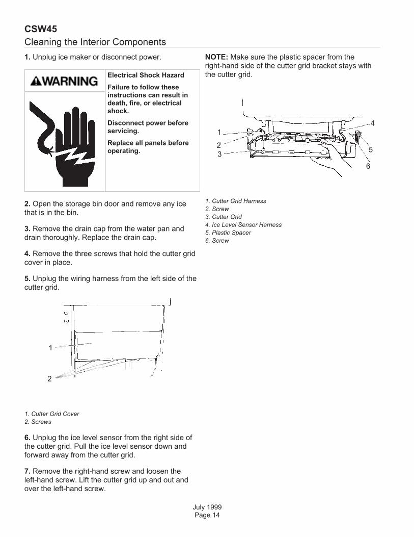
Cleaning the Interior Components
1. Unplug ice maker or disconnect power.
2. Open the storage bin door and remove any icethat is in the bin.
3. Remove the drain cap from the water pan anddrain thoroughly. Replace the drain cap.
4. Remove the three screws that hold the cutter gridcover in place.
5. Unplug the wiring harness from the left side of thecutter grid.
1. Cutter Grid Cover
2. Screws
6. Unplug the ice level sensor from the right side ofthe cutter grid. Pull the ice level sensor down andforward away from the cutter grid.
7. Remove the right-hand screw and loosen theleft-hand screw. Lift the cutter grid up and out andover the left-hand screw.
NOTE: Make sure the plastic spacer from theright-hand side of the cutter grid bracket stays withthe cutter grid.
1. Cutter Grid Harness
2. Screw
3. Cutter Grid
4. Ice Level Sensor Harness
5. Plastic Spacer
6. Screw
CSW45
July 1999Page 14
1
2
1
2
3
4
5
6
Electrical Shock Hazard
Failure to follow theseinstructions can result indeath, fire, or electricalshock.
Disconnect power beforeservicing.
Replace all panels beforeoperating.

Cleaning Interior - continued
8. Remove the two screws that hold the water pan inplace. Push down with one hand on the front of thepan while pulling forward on the bottom back side.
9. Wash the interior components (cutter grid, exteriorof hoses, and water pan) and the storage bin, doorgasket, and ice scoop with mild soap or detergentand warm water. Rinse in clean water. Then cleanthe same parts with a solution of 1 tablespoon (15mL) of household bleach in 1 gallon (3.8 L) warmwater. Rinse again thoroughly in clean water.
NOTE: Do not remove hoses. Do not wash plasticparts in dishwasher. They cannot withstandtemperatures above 145°F (63°C).
10. Replace water pan by pushing back on thebottom with one hand while pushing up and back onthe top. Secure the water pan by replacing bothscrews.
11. Check the following:
• Drain cap from the water pan is in place.
• Hose from water pan is inserted into storage bindrain opening.
12. Slide the cutter grid back into place and secure itby replacing the right-hand screw and plastic spacer.Then tighten the left-hand screw. Reconnect thecutter grid and ice level sensor harnesses.
Changing the Light Bulb
The ice maker has a light bulb in the top of thestorage bin.
To replace it, open the bin door and follow theseinstructions:
1. Unplug ice maker or disconnect power.
2. Remove the three screws that hold the cutter gridcover in place. Reach behind the control panel andpull the light bulb down from the ceiling.
3. Replace with a 12-volt wedge base-type bulb(automotive #917). Locate the light bulb receptacle inthe ceiling behind the control panel. Align the flatedge of the light bulb with the receptacle and snapthe bulb into place.
4. Replace the cutter grid cover with three screws.
5. Plug in ice maker or reconnect power.
CSW45
July 1999Page 15

Vacation and Moving Care
To shut down the ice maker:
1. Unplug ice maker or disconnect power.
2. Remove all ice from storage bin.
3. Shut off the water supply.
4. Remove the two screws in the lower access paneland the two screws from the base grille area of thefront panel support. Pull forward to remove the loweraccess panel.
5. Disconnect the inlet and outlet lines to watervalve. Allow these lines to drain and then reconnectto the valve.
6. Replace lower access panel and screws. Drainwater from water pan by removing the drain cap.Also, remove water from drain line.
7. Before using again, clean the ice maker andstorage bin.
8. Plug in ice maker or reconnect power.
NOTE: All components of the ice maker arepermanently lubricated at the factory. They shouldnot require any additional oiling throughout thenormal life of the machine.
WA so can result in death orelectrical shock.
CSW45
July 1999Page 16

Before Calling for Service
Try the solutions suggested here first in order toavoid the cost of an unnecessary service call.
Unit does not run
n Is the control set to ON?
Be sure that the control is set to ON.
n Is the power cord plugged in?
Firmly plug the cord into a live outlet with propervoltage.
n Has a household fuse or circuit breakertripped?
Replace the fuse or reset the circuit.
n Is the room temperature cooler than normal?
Room temperature must be above 55°F (13°C).
Otherwise, bin thermostat may sense cold roomtemperature and shut off even though bin is not fullof ice. Also, unit may not restart once it does shut off.
Unit runs but produces no ice
n Is the control set to ON?
Be sure that the control is set to ON.
n Is the water supply connected?
Make sure the water supply is properly connectedand turned on.
Unit runs but produces very little ice
n Is the room temperature hotter than normal?
Room temperatures of more than 90°F (32°C) willnormally reduce ice production.
n Is the condenser dirty?
Dirt or lint may be blocking the airflow through thecondenser. See the “Cleaning the Condenser”section.
n Is there scale buildup in the ice maker?
If there is white scale buildup in the ice maker’swater or freezing system, you should clean the icemaker. See the “Cleaning the Ice Maker System”and the “Cleaning the Interior Components” sections.
Grid is not cutting ice sheets
n Is the cutter grid securely in place?
Unplug the ice maker or disconnect power. Removethe cutter grid cover and check the cutter gridharness plug to make sure the connection is secure.
Taste in ice cubes
n Is there unusually high mineral content in thewater supply?
The water may need to be filtered or treated.
n Are there food items stored in the ice bin?
Do not store any foods in the ice bin.
n Were all the packaging materials removed?
Make sure that all packaging materials wereremoved at the time of installation. Service Diagnosis
CSW45
July 1999Page 17
Technical Service Diagnosis
CSW45
July 1999Page 18
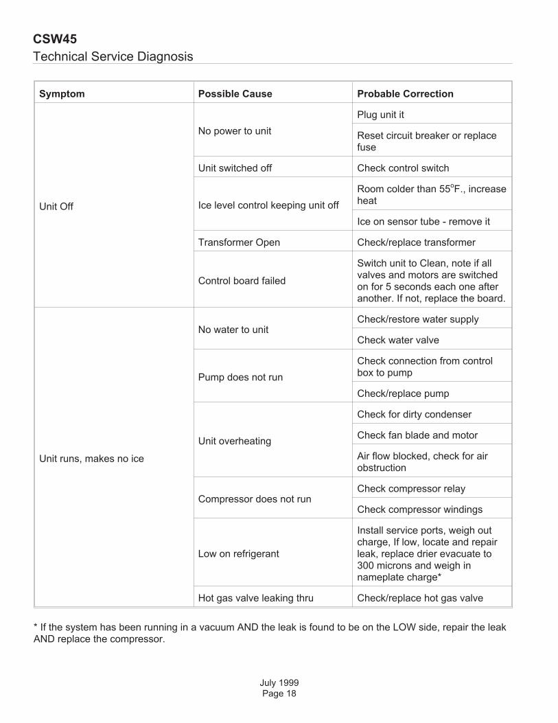
Symptom Possible Cause Probable Correction
Unit Off
No power to unit
Plug unit it
Reset circuit breaker or replacefuse
Unit switched off Check control switch
Ice level control keeping unit off
Room colder than 55oF., increase
heat
Ice on sensor tube - remove it
Transformer Open Check/replace transformer
Control board failed
Switch unit to Clean, note if allvalves and motors are switchedon for 5 seconds each one afteranother. If not, replace the board.
Unit runs, makes no ice
No water to unitCheck/restore water supply
Check water valve
Pump does not run
Check connection from controlbox to pump
Check/replace pump
Unit overheating
Check for dirty condenser
Check fan blade and motor
Air flow blocked, check for airobstruction
Compressor does not runCheck compressor relay
Check compressor windings
Low on refrigerant
Install service ports, weigh outcharge, If low, locate and repairleak, replace drier evacuate to300 microns and weigh innameplate charge*
Hot gas valve leaking thru Check/replace hot gas valve
* If the system has been running in a vacuum AND the leak is found to be on the LOW side, repair the leakAND replace the compressor.
Technical Service Diagnosis
July 1999Page 19
CSW45
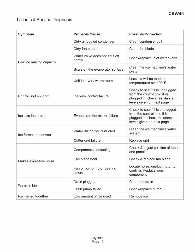
Symptom Probable Cause Possible Correction
Low ice making capacity
Dirty air cooled condenser Clean condenser coil
Dirty fan blade Clean fan blade
Water valve does not shut offtightly
Check/replace inlet water valve
Scale on the evaporator surfaceClean the ice machine’s watersystem
Unit in a very warm roomLess ice will be made intemperatures over 90
oF.
Unit will not shut off Ice level control failure
Check to see if it is unpluggedfrom the control box, if itsplugged in, check resistancelevels given on next page
Ice size incorrect Evaporator thermistor failure
Check to see if it is unpluggedfrom the control box, if itsplugged in, check resistancelevels given on next page
Ice formation unevenWater distributor restricted
Clean the ice machine’s watersystem
Cutter grid failure Replace grid
Makes excessive noise
Components contactingCheck & adjust position of tubesand panels
Fan blade bent Check & replace fan blade
Fan or pump motor bearingfailure
Locate noise, unplug motor toconfirm. Replace worncomponent.
Water in binDrain plugged Clean out drain
Drain pump failed Check/replace pump
Ice melted together Low amount of ice used Remove ice

Technical Information
Performance Data
Ice Bin Thermistor
Evaporator Thermistor
Components
CSW45
October 2005Page 20
TemperatureSuction Pressure at Endof Freeze Cycle
Head Pressure at End ofFreeze Cycle
Cycle Time in Minutes
Air 70oF. Water 60
oF. 1 - 4 65 - 80 18 - 22
Air 90oF. Water 60
oF. 2 - 5 85 - 100 22 - 27
Air 100oF. Water 60
oF. 2 -6 85 - 105 28 - 35
Air 70oF. Water 80
oF. 1 - 4 65 - 80 20 - 25
Air 90oF. Water 80
oF. 2 - 5 85 - 100 23 - 30
Air 100oF. Water 80
oF. 2 - 6 85- 105 30 - 38
Temperature Resistance Temperature Resistance
Bin Shut Off 40oF. � 1
o25.9k� � 3% 35
oF. � 1
o29.8k� � 3%
Cut-IN Cut-OUT Water valve off (harvest)
IceThickness
Temperature Resistance Temperature Resistance Temperature Resistance
Normal 52.5oF. � .3
o18.7k� � 1% 6.5
oF. � .3
o69.5k� � 1% 40
oF. � .3
o25.9k� � 1%
Thick 52.5oF. � .3
o18.7k� � 1% 4.5
oF. � .3
o73.9k� � 1% 40
oF. � .3
o25.9k� � 1%
Thin 52.5oF. � .3
o18.7k� � 1% 8.5
oF. � .3
o65.3k� � 1% 40
oF. � .3
o25.9k� � 1%
• Compressor: Embraco, 244 watts .2 HP
• Cutter Grid: 8.7 volts
• Light: 8.7 volts
Electrical Sequence
The CSW45’s operation is controlled by an electronicboard. This board takes in data from two thermistors:The Ice Bin Thermistor and the EvaporatorThermistor. The two resistances the thermistorssupply, along with the position of the control switch,determine the cycles of the ice machine.
Start Up
The inlet water valve opens for about two minutes tofill the reservoir.
The water pump starts and stays on for about aminute, then shuts off.
Then the inlet water valve opens again for twominutes. After it closes, the compressor, pump andfan motor start.
Freeze
The compressor, fan motor and water pump are alloperating and stay in a Freeze cycle until theevaporator thermistor reaches 6.5
oF. That signals
the control board to place the unit into a harvestcycle.
Harvest
The compressor and hot gas valve are both poweredduring the harvest cycle. The fan and pump are OFF.The machine stays in the harvest cycle until theevaporator thermistor senses 52
oF. If the bin is not
full, the unit goes into another freeze cycle.
Bin Full
The unit will shut down when the ice level sensorsenses a temperature of less than 35
oF. It will restart
when the thermistor’s temperature increases to 41oF.
Clean
The Clean Cycle lasts about 47 minutes. During thefirst minute all motors and valves will be switched onin sequence for 5 seconds each. This includes theinlet water valve, condenser fan, hot gas solenoidvalve, water spray pump and the compressor. Thisearly portion of the Clean Cycle doubles as adiagnostic cycle. The last 46 minutes of the clean thecompressor, water spray pump and hot gas valve willbe on.
July 1999Page 21
CSW45

Repair Information
Cutting Grid
The cutting grid rests on two shelves molded into thebin liner. It is also secured to the liner with twoscrews.
1. Remove the three screws holding the cutter gridcover to the grid.
2. Disconnect the three wiring harness plugs fromthe control box.
3. Remove the screw holding the grid to the rightside of the liner.
4. Loosen, but don’t remove the screw holding thegrid to the left side of the liner.
Lift the front of the grid until the slot in the grid clearsthe screw, the pull the grid forward and out of thecabinet.
Control Box
The control box is located above the cutting grid. It issuspended from the top panel by 4 screws. Its wiringharness routes out the back of the control boxthrough a molded channel.
July 1999Page 22
CSW45
Remove 3 Screws
Wire Harness Plugs
Loosen ThisScrew
Remove ThisScrew

Repair Information
Water Slide
The water slide is mounted to the front of theevaporator and diverts water to the reservoir. It isconnected to the evaporator by two screws. Removethe cutter grid first to get access to it.
Reservoir
The reservoir is located below the evaporator, and ismounted to the bin liner with two screws.
Water Pump
The water pump is located below the evaporator. It ismounted to the bin liner with three screws. It alsohas a quick-connect electrical plug.
Evaporator Thermistor
This thermistor is a set of two red wires that connectto the control box. There is a molded portion in oneof the wires with a clip on it. That portion clips ontothe part of the suction line under the middle of theevaporator that runs front to back.
Compressor
The terminals for the compressor are accessible onlyfrom the back of the unit. Compressor replacementrequires lifting up of the cabinet at the front.
Fan Motor
The fan motor and/or blade is only accessible afterthe cabinet has been tilted up.
Component Compartment Access
Note: Chassis does NOT pull out.
Unplug the unit from the power supply. If built in, pullit out from the counter. Note: The water and drainlines may have to be disconnected.
1 Remove the front panel.
2. Remove the leveling legs from the cabinet.
3. Remove two screws at the front holding chassisbase to cabinet.
4. Tilt the entire ice maker back far enough to gainaccess to the compartment.
July 1999Page 23
CSW45
Leveling Leg
Screws
Screws

Repair Information
When tilting the cabinet, be sure it is secure to avoidany possibility that it will tip too far back or fallforward.
July 1999Page 24
CSW45
Illustration of Cabinet in Service Position
Fan Motor,viewed from
the back.