Embed Size (px)
Citation preview
Stability of Equilibrium: Buckling
Introduction
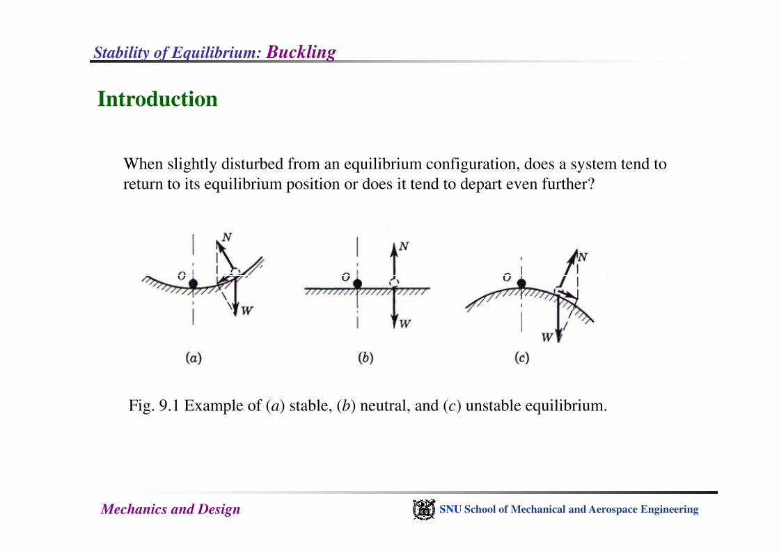
When slightly disturbed from an equilibrium configuration, does a system tend to
return to its equilibrium position or does it tend to depart even further?
Mechanics and Design SNU School of Mechanical and Aerospace Engineering
Fig. 9.1 Example of (a) stable, (b) neutral, and (c) unstable equilibrium.
Stability of Equilibrium: Buckling
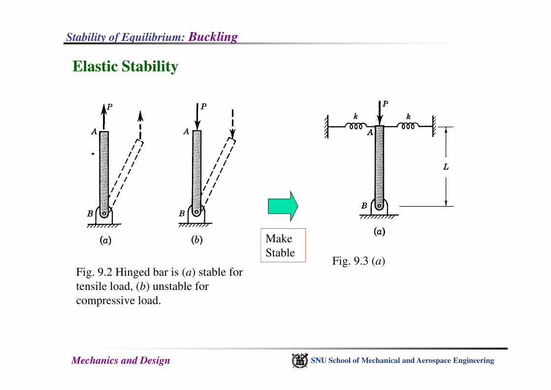
Elastic Stability
Mechanics and Design SNU School of Mechanical and Aerospace Engineering
Fig. 9.2 Hinged bar is (a) stable for
tensile load, (b) unstable for
compressive load.
Make
StableFig. 9.3 (a)
Stability of Equilibrium: Buckling
Mechanics and Design SNU School of Mechanical and Aerospace Engineering
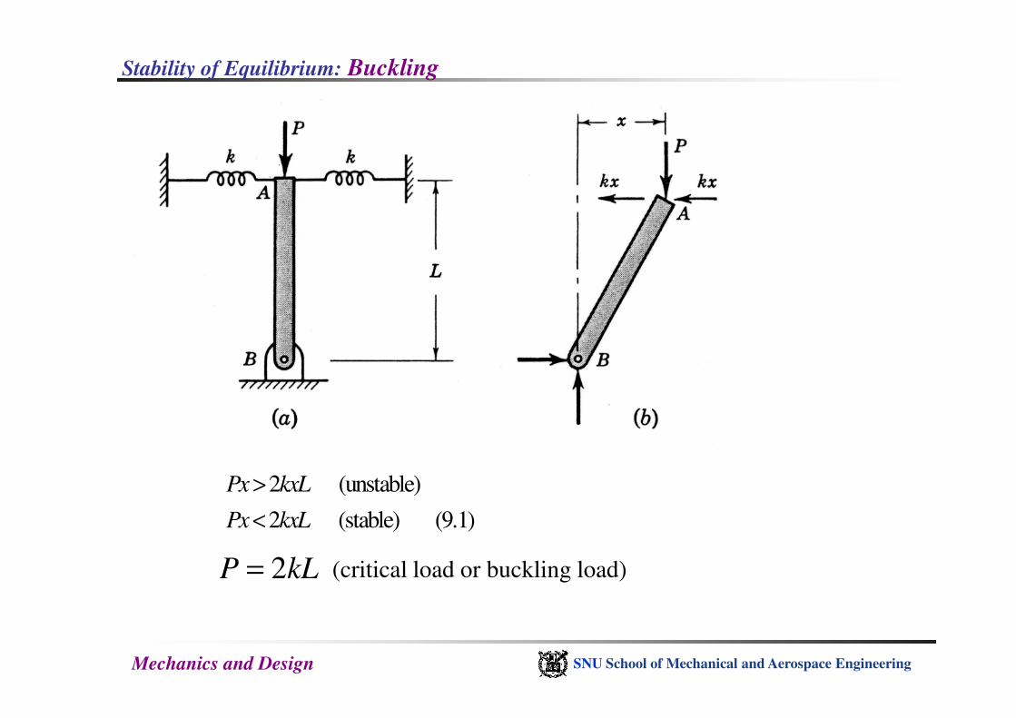
2 (unstable)
2 (stable) (9.1)
Px kxL
Px kxL
>
<
2P kL= (critical load or buckling load)
Stability of Equilibrium: Buckling
Mechanics and Design SNU School of Mechanical and Aerospace Engineering
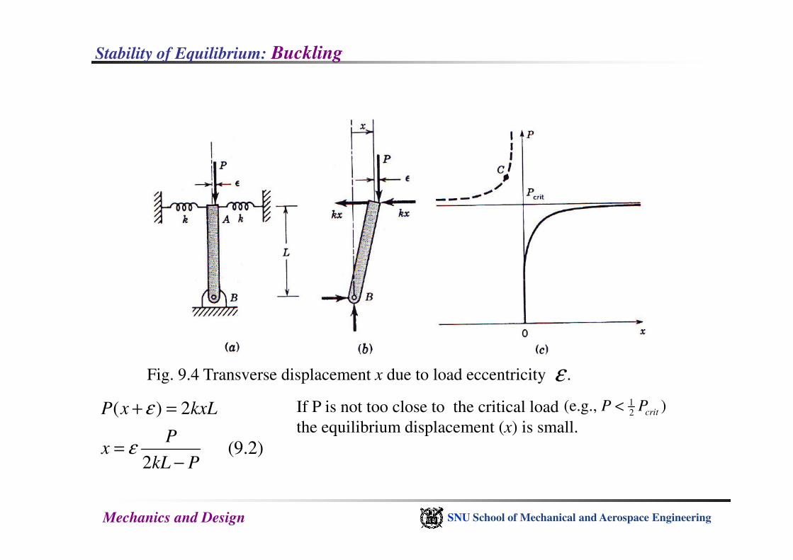
Fig. 9.4 Transverse displacement x due to load eccentricity .ε
( ) 2
(9.2)2
P x kxL
Px
kL P
ε
ε
+ =
=−
If P is not too close to the critical load
the equilibrium displacement (x) is small.
12
(e.g., )critP P<
Stability of Equilibrium: Buckling
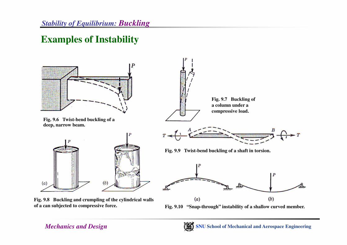
Examples of Instability
Fig. 9.6 Twist-bend buckling of a deep, narrow beam.
Fig. 9.7 Buckling of
a column under a
compressive load.
Mechanics and Design SNU School of Mechanical and Aerospace Engineering
deep, narrow beam.
Fig. 9.9 Twist-bend buckling of a shaft in torsion.
Fig. 9.8 Buckling and crumpling of the cylindrical walls
of a can subjected to compressive force. Fig. 9.10 “Snap-through” instability of a shallow curved member.

Stability of Equilibrium: Buckling
Elastic Stability of Flexible Columns
Fig. 9.11 (a) Beam subjected to
longitudinal and transverse loads; (b) free-
body sketch of element of beam.
Mechanics and Design SNU School of Mechanical and Aerospace Engineering
( ) 0
( ) ( ) 0 (9.3)2 2
b b b
V V V q x
x xM M M V V V P v
+ ∆ − + ∆ =
∆ ∆+ ∆ − + + + ∆ + ∆ =
0
0 (9.4)b
dVq
dx
dM dvV P
dx dx
+ =
+ + =
2
2(9.5)
b
d vEI M
dx=
2 2
2 2( ) ( ) (9.6)
d d v d dvEI P q
dx dx dx dx+ =
body sketch of element of beam.
Stability of Equilibrium: Buckling
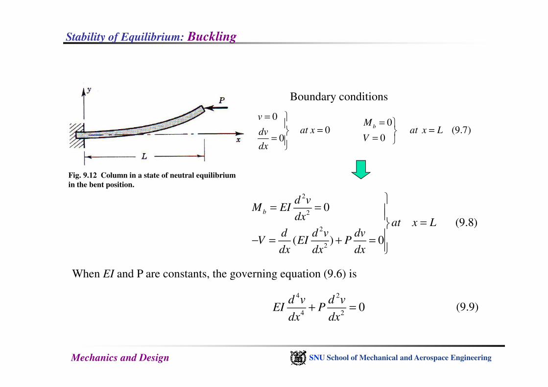
00
0 (9.7)00
b
vM
at x at x LdvV
dx
= =
= = ==
Boundary conditions
2d v
Fig. 9.12 Column in a state of neutral equilibrium
in the bent position.
Mechanics and Design SNU School of Mechanical and Aerospace Engineering
2
2
2
2
0
(9.8)
( ) 0
b
d vM EI
dxat x L
d d v dvV EI P
dx dx dx
= =
=− = + =
When EI and P are constants, the governing equation (9.6) is
4 2
4 20
d v d vEI P
dx dx+ = (9.9)
Stability of Equilibrium: Buckling
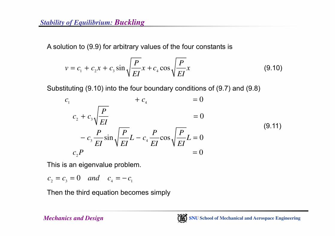
A solution to (9.9) for arbitrary values of the four constants is
1 2 3 4sin cos
P Pv c c x c x c x
EI EI= + + + (9.10)
Substituting (9.10) into the four boundary conditions of (9.7) and (9.8)
1 4
2 3
0
0
c c
Pc c
EI
+ =
+ =
Mechanics and Design SNU School of Mechanical and Aerospace Engineering
2 3
3 4
2
0
sin cos 0
0
c cEI
P P P Pc L c L
EI EI EI EI
c P
+ =
− − =
=
(9.11)
This is an eigenvalue problem.
2 3 4 10c c and c c= = = −
Then the third equation becomes simply
Stability of Equilibrium: Buckling
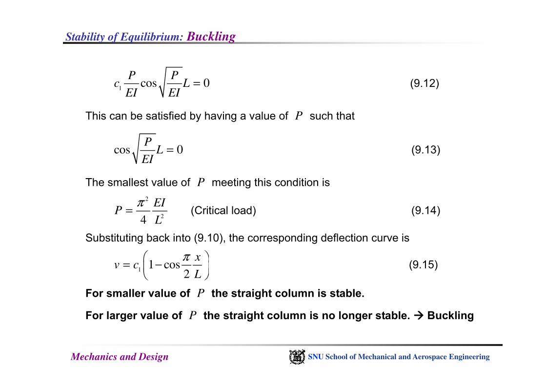
1cos 0
P Pc L
EI EI= (9.12)
This can be satisfied by having a value of P such that
cos 0P
LEI
= (9.13)
The smallest value of P meeting this condition is
Mechanics and Design SNU School of Mechanical and Aerospace Engineering
2
24
EIP
L
π= (Critical load) (9.14)
Substituting back into (9.10), the corresponding deflection curve is
11 cos
2
xv c
L
π = −
(9.15)
For smaller value of P the straight column is stable.
For larger value of P the straight column is no longer stable. ���� Buckling
Stability of Equilibrium: Buckling
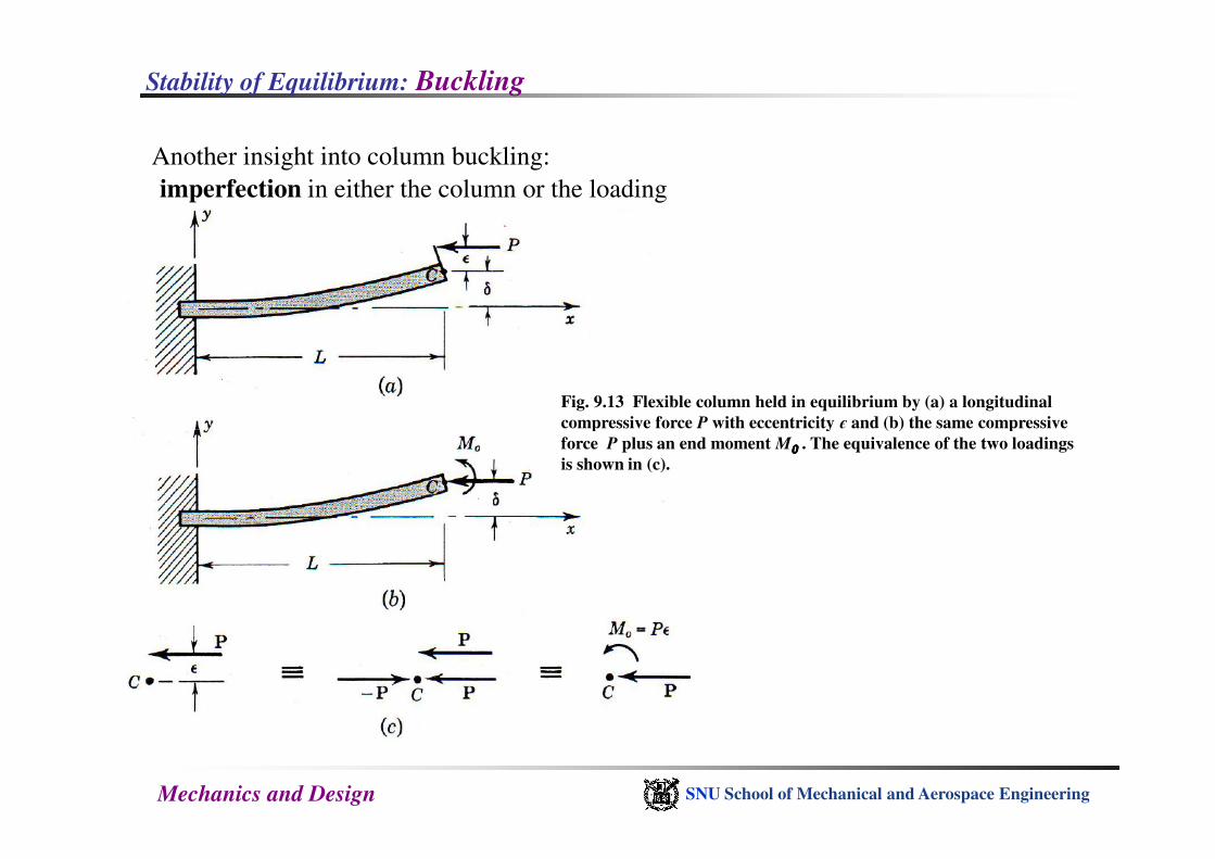
Another insight into column buckling:
imperfection in either the column or the loading
Fig. 9.13 Flexible column held in equilibrium by (a) a longitudinal
compressive force P with eccentricity є and (b) the same compressive
Mechanics and Design SNU School of Mechanical and Aerospace Engineering
compressive force P with eccentricity є and (b) the same compressive
force P plus an end moment M0000 . The equivalence of the two loadings
is shown in (c).
Stability of Equilibrium: Buckling
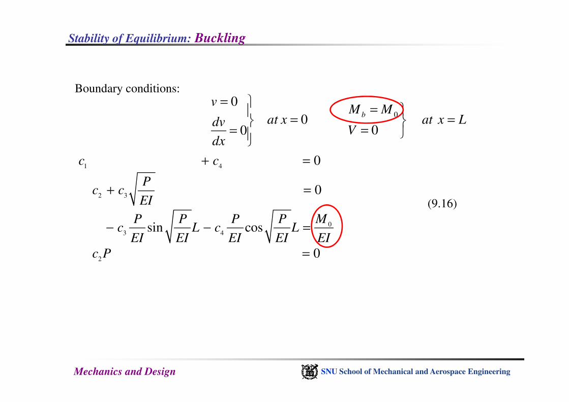
Boundary conditions:
0
0
000
b
vM M
at x at x LdvV
dx
= =
= = ==
(9.16)
1 4
2 3
0
0
c c
Pc c
EI
+ =
+ =
Mechanics and Design SNU School of Mechanical and Aerospace Engineering
(9.16)
0
3 4
2
sin cos
0
EI
MP P P Pc L c L
EI EI EI EI EI
c P
− − =
=
Stability of Equilibrium: Buckling
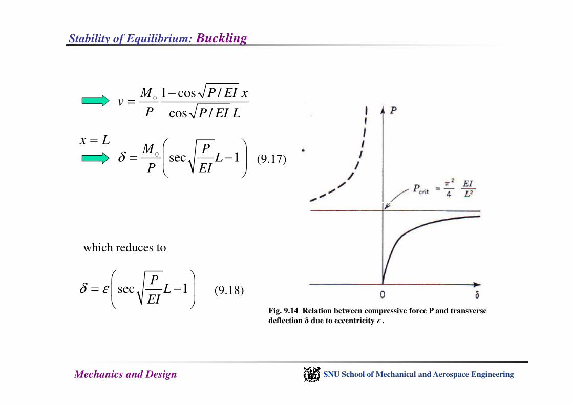
01 cos /
cos /
M P EI xv
P P EI L
−=
0 sec 1M P
LP EI
δ
= −
x L=
(9.17)
Mechanics and Design SNU School of Mechanical and Aerospace Engineering
which reduces to
sec 1P
LEI
δ ε
= −
(9.18)
Fig. 9.14 Relation between compressive force P and transverse
deflection δ due to eccentricity є .

Stability of Equilibrium: Buckling
Fig. 9.15 Critical loads for (a) clamped-free, (b)
hinged-hinged, (c) clamped-hinged, and (d)
clamped-clamped columns. In each case the
constant c shown is to be inserted in the formula
Pcrit = cEI/L2.
Mechanics and Design SNU School of Mechanical and Aerospace Engineering
Stability of Equilibrium: Buckling
Mechanics and Design SNU School of Mechanical and Aerospace Engineering
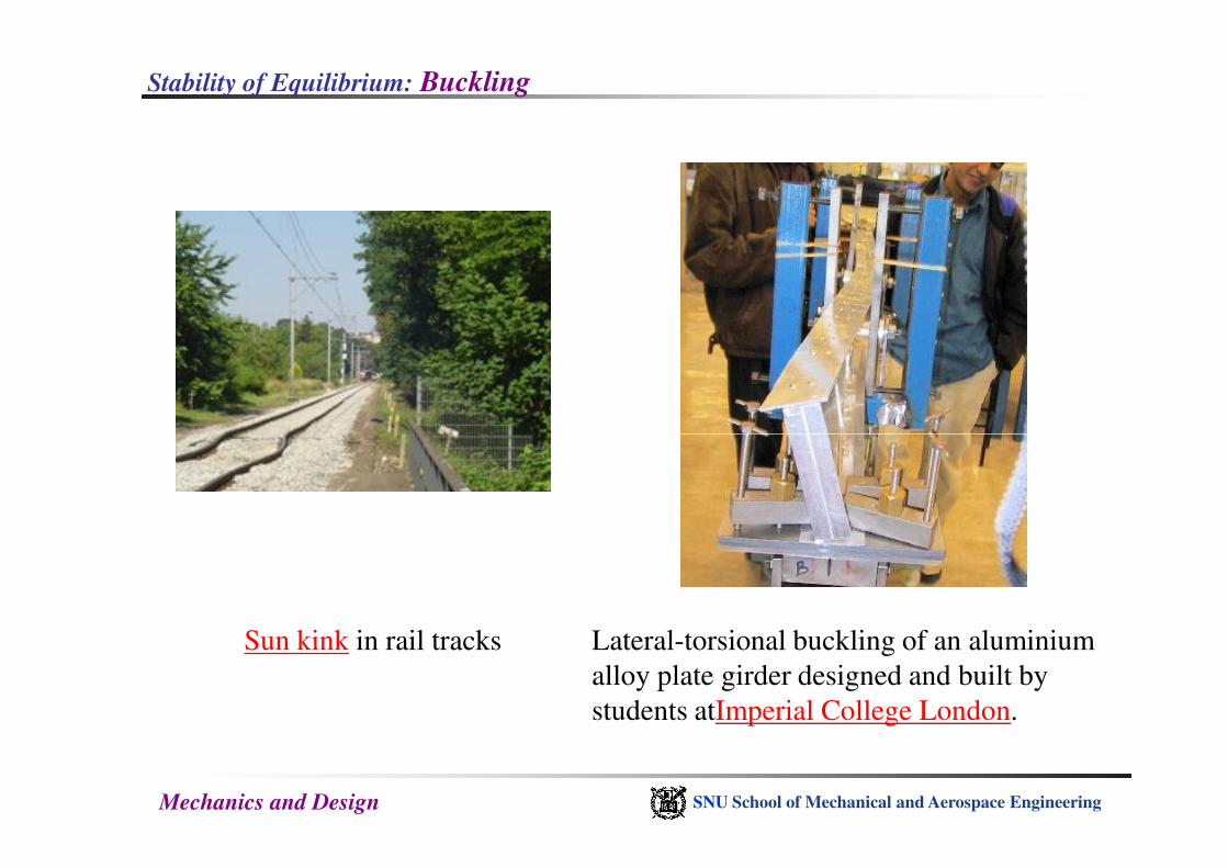
Lateral-torsional buckling of an aluminium
alloy plate girder designed and built by
students atImperial College London.
Sun kink in rail tracks
Stability of Equilibrium: Buckling
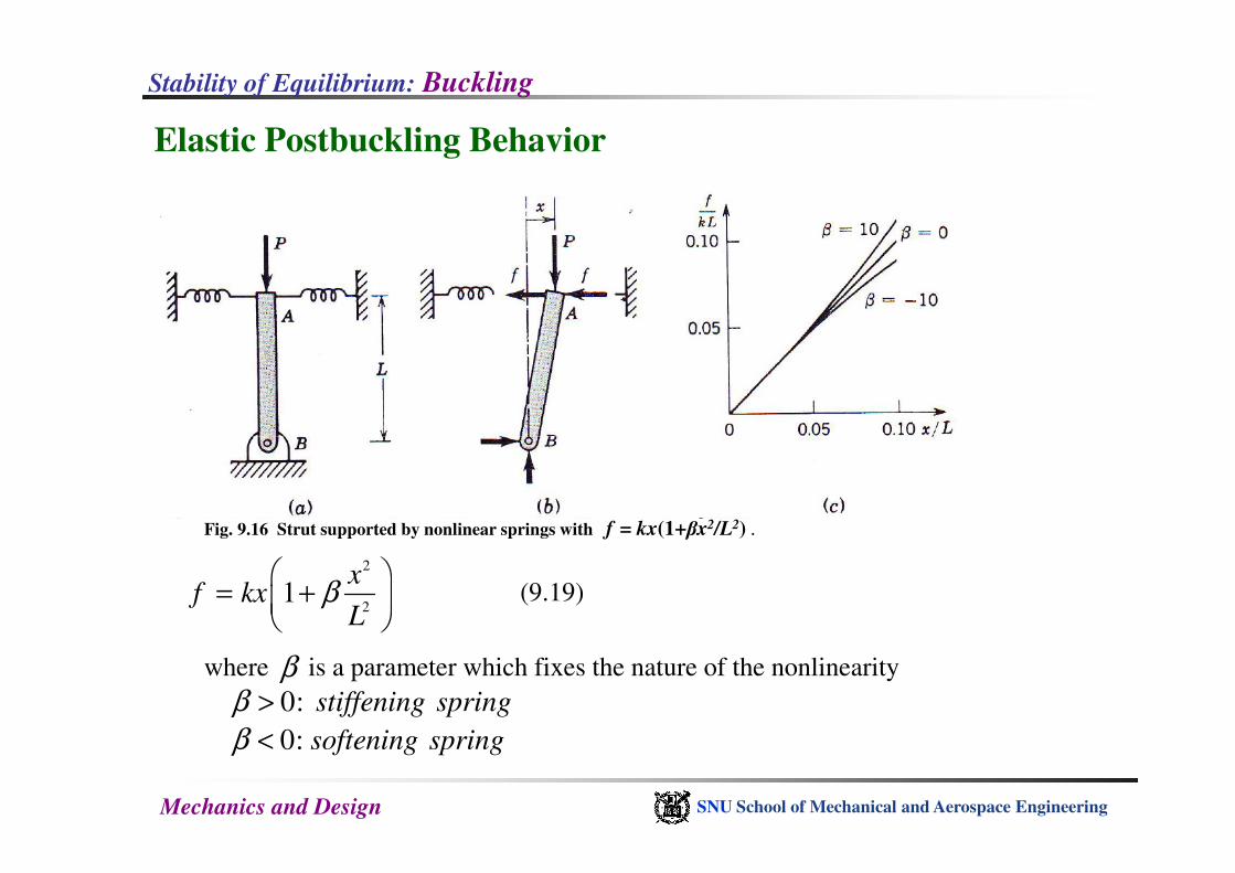
Elastic Postbuckling Behavior
Mechanics and Design SNU School of Mechanical and Aerospace Engineering
2
21
xf kx
Lβ
= +
(9.19)
where is a parameter which fixes the nature of the nonlinearityβ0:
0:
stiffening spring
softening spring
β
β
>
<
Fig. 9.16 Strut supported by nonlinear springs with f = kx(1+βx2/L2) .

Stability of Equilibrium: Buckling
From Fig. 9.16(b)2
22 1 0
xPx kLx
Lβ
− + =
2
20 2 1
xx or P kL
Lβ
= = +
2crit
P kL= B : bifurcation point
Mechanics and Design SNU School of Mechanical and Aerospace Engineering
the branch BD represents unstable equilibrium positions.In every case
The branch BC represents
0
0
0
for
for
for
β
β
β
>
=
<
stable equilibrium positions.
neutral equilibrium positions.
unstable equilibrium positions.
Fig. 9.17 Ideal postbuckling curves for (a) ββββ = 10, (b) β = 0, (c) β = -10.
Stability of Equilibrium: Buckling
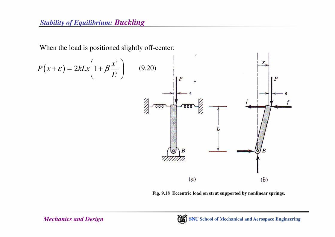
( )2
22 1
xP x kLx
Lε β
+ = +
(9.20)
When the load is positioned slightly off-center:
Mechanics and Design SNU School of Mechanical and Aerospace Engineering
Fig. 9.18 Eccentric load on strut supported by nonlinear springs.
Stability of Equilibrium: Buckling
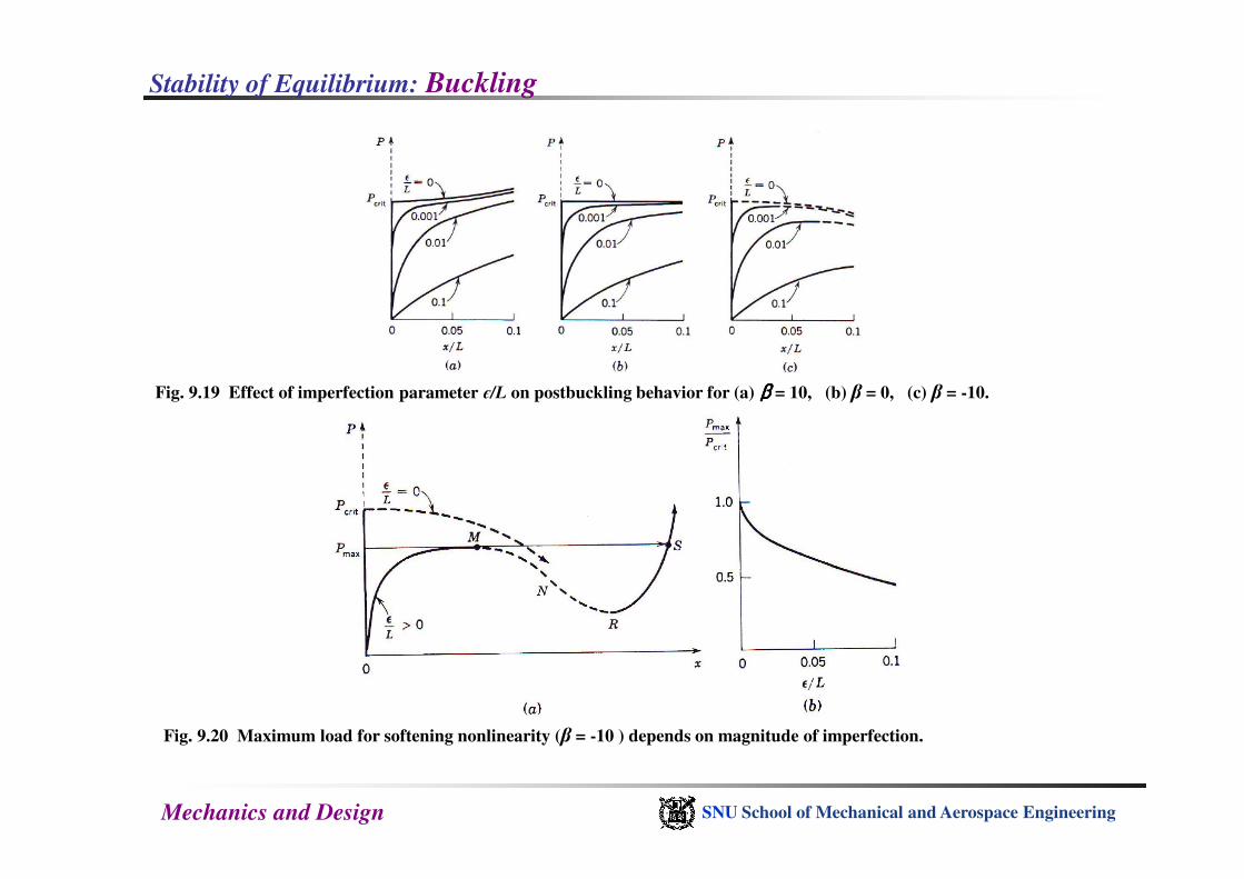
Fig. 9.19 Effect of imperfection parameter є/L on postbuckling behavior for (a) ββββ = 10, (b) β = 0, (c) β = -10.
Mechanics and Design SNU School of Mechanical and Aerospace Engineering
Fig. 9.20 Maximum load for softening nonlinearity (β = -10 ) depends on magnitude of imperfection.
Stability of Equilibrium: Buckling
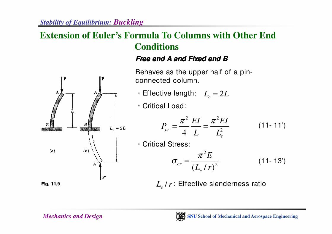
Extension of Euler’s Formula To Columns with Other End
Conditions
Free end A and FFree end A and FFree end A and FFree end A and Fixed end Bixed end Bixed end Bixed end B
Behaves as the upper half of a pin-
connected column.
ㆍEffective length:
ㆍCritical Load:
LLe 2=
2 2EI EIπ π
Mechanics and Design SNU School of Mechanical and Aerospace Engineering
ㆍCritical Stress:
2 2
24cr
e
EI EIP
L L
π π= =
2
2
)/( rL
E
e
cr
πσ =
: Effective slenderness ratiorLe /
(11- 11’)
(11- 13’)
Stability of Equilibrium: Buckling
Extension of Euler’s Formula To Columns with Other End
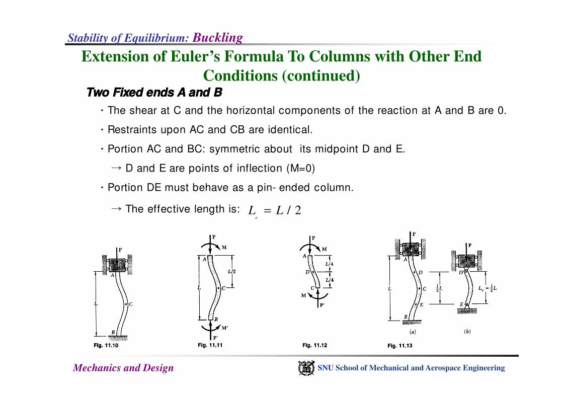
Conditions (continued)Two Fixed ends A and BTwo Fixed ends A and BTwo Fixed ends A and BTwo Fixed ends A and B
ㆍThe shear at C and the horizontal components of the reaction at A and B are 0.
ㆍRestraints upon AC and CB are identical.
ㆍPortion AC and BC: symmetric about its midpoint D and E.
→ D and E are points of inflection (M=0)
ㆍPortion DE must behave as a pin- ended column.
Mechanics and Design SNU School of Mechanical and Aerospace Engineering
→ The effective length is: / 2e
L L=
Stability of Equilibrium: Buckling
Extension of Euler’s Formula To Columns with Other End
Conditions (continued)
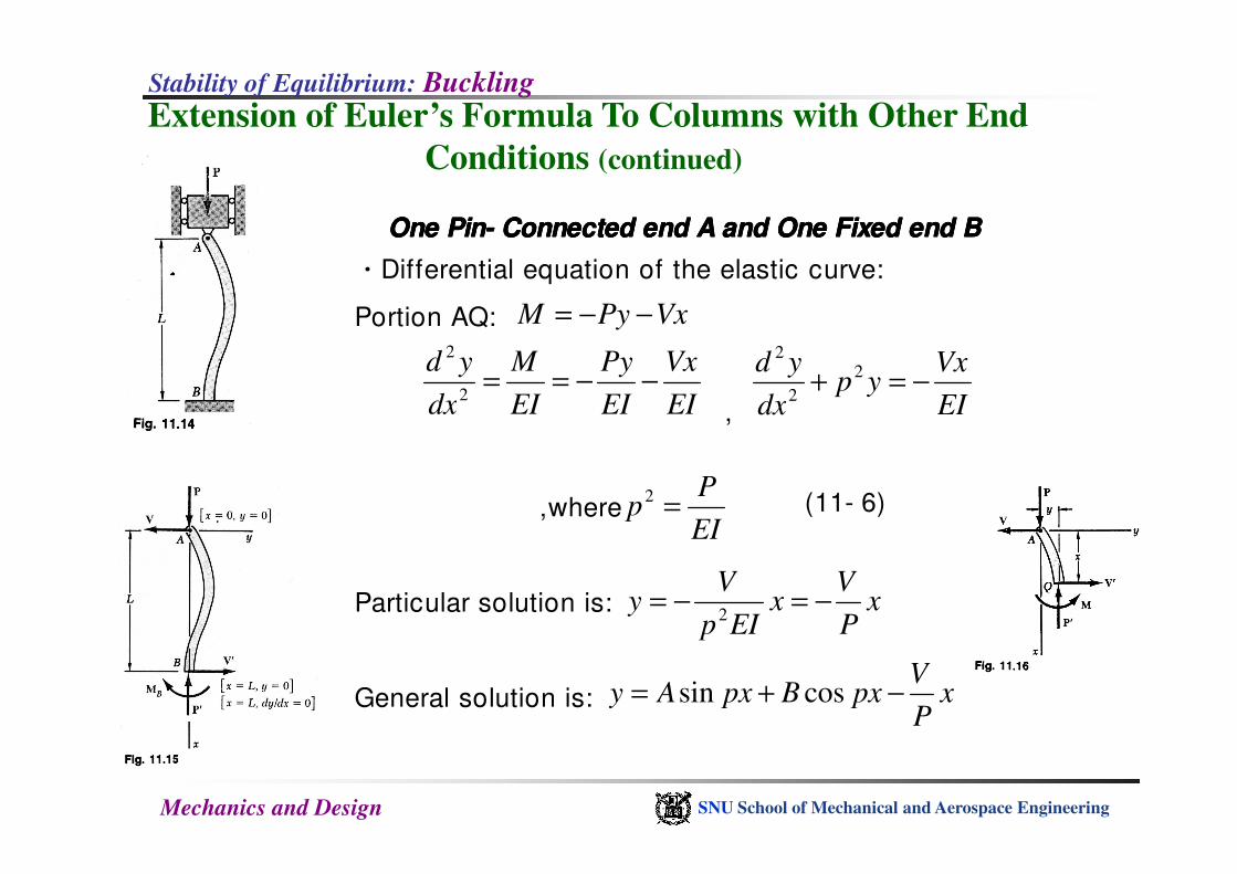
One PinOne PinOne PinOne Pin---- Connected end A and One Fixed end BConnected end A and One Fixed end BConnected end A and One Fixed end BConnected end A and One Fixed end B
ㆍDifferential equation of the elastic curve:
Portion AQ:
,
VxPyM −−=
EI
Vx
EI
Py
EI
M
dx
yd−−==
2
2
EI
Vxyp
dx
yd−=+ 2
2
2
Mechanics and Design SNU School of Mechanical and Aerospace Engineering
,where
Particular solution is:
General solution is:
EI
Pp =2
xP
Vx
EIp
Vy −=−=
2
xP
VpxBpxAy −+= cossin
(11- 6)
Stability of Equilibrium: Buckling
Extension of Euler’s Formula To Columns with Other End
Conditions (continued)
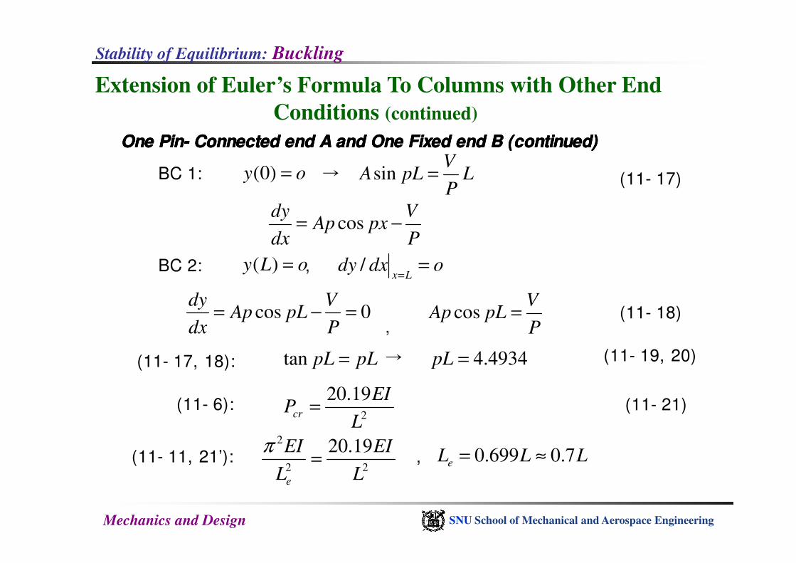
One PinOne PinOne PinOne Pin---- Connected end A and One Fixed end B (continued)Connected end A and One Fixed end B (continued)Connected end A and One Fixed end B (continued)Connected end A and One Fixed end B (continued)
BC 1: →
BC 2: ,
oy =)0(
oLy =)( odxdyLx
==
/
LP
VpLA =sin
P
VpxAp
dx
dy−= cos
(11- 17)
Mechanics and Design SNU School of Mechanical and Aerospace Engineering
,
→
0cos =−=P
VpLAp
dx
dy
P
VpLAp =cos
pLpL =tan 4934.4=pL
2
19.20
L
EIPcr =
(11- 18)
(11- 19, 20)(11- 17, 18):
(11- 6): (11- 21)
(11- 11, 21’): , 22
2 19.20
L
EI
L
EI
e
=π
LLLe 7.0699.0 ≈=
Stability of Equilibrium: Buckling
Extension of Euler’s Formula To Columns with Other End
Conditions (continued)
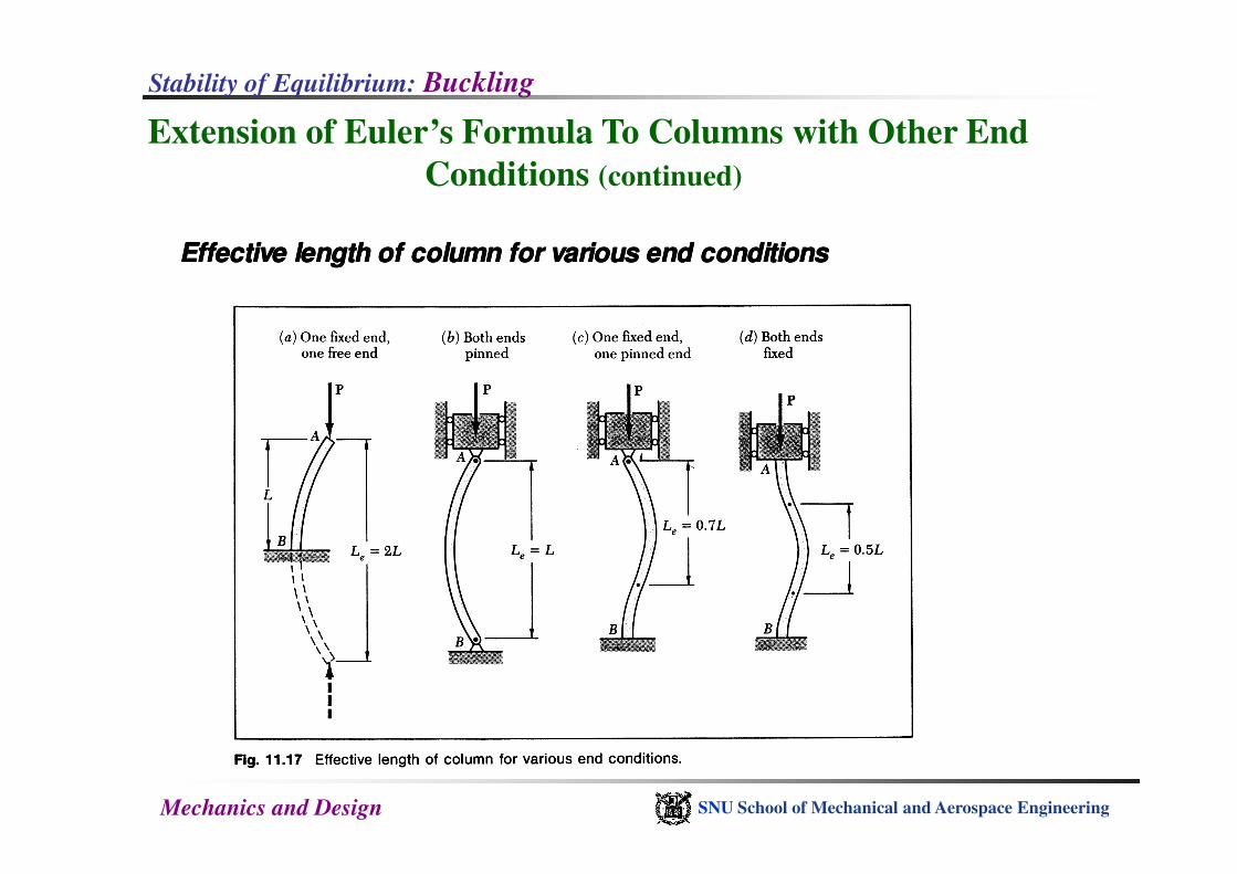
Effective length of column for various end conditionsEffective length of column for various end conditionsEffective length of column for various end conditionsEffective length of column for various end conditions
Mechanics and Design SNU School of Mechanical and Aerospace Engineering
Stability of Equilibrium: Buckling
Extension of Euler’s Formula To Columns with Other End
Conditions (continued)
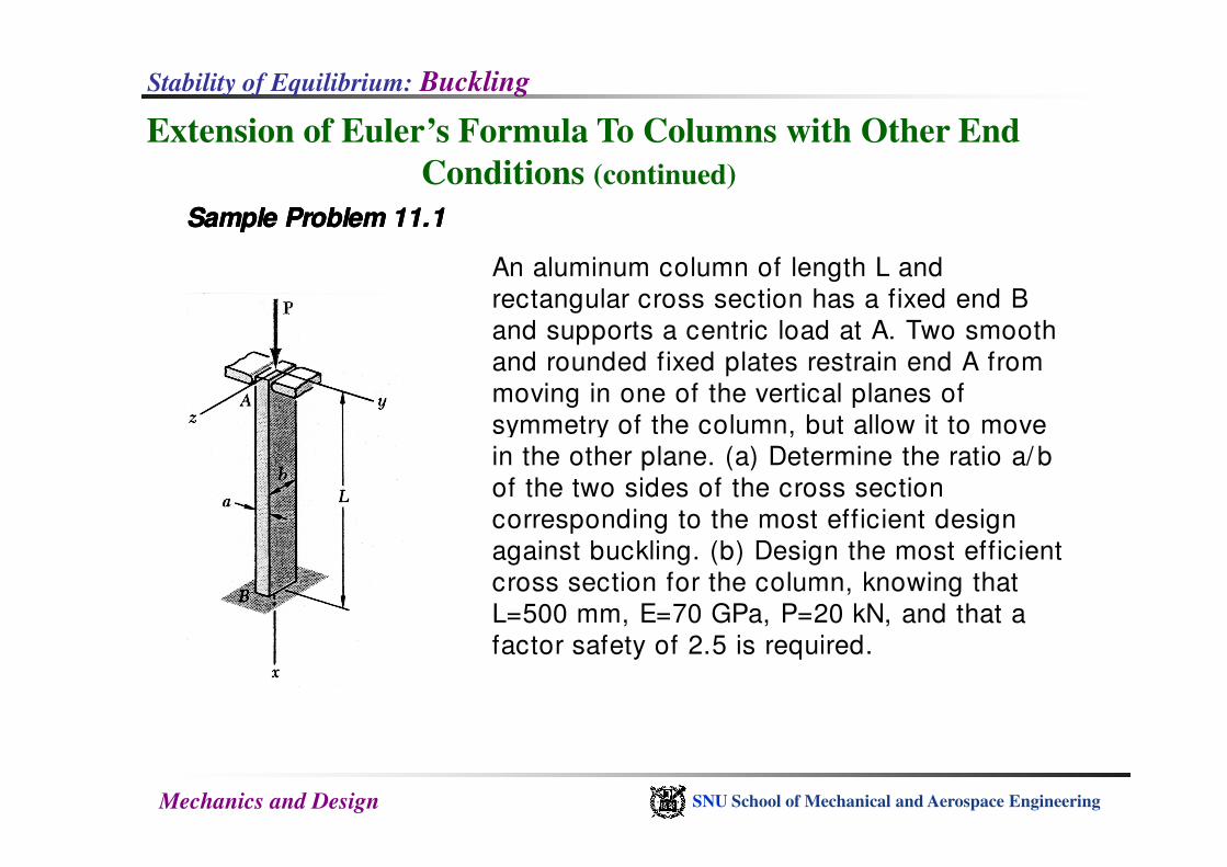
Sample Problem 11.1Sample Problem 11.1Sample Problem 11.1Sample Problem 11.1
An aluminum column of length L and
rectangular cross section has a fixed end B
and supports a centric load at A. Two smooth
and rounded fixed plates restrain end A from
moving in one of the vertical planes of
symmetry of the column, but allow it to move
Mechanics and Design SNU School of Mechanical and Aerospace Engineering
symmetry of the column, but allow it to move
in the other plane. (a) Determine the ratio a/ b
of the two sides of the cross section
corresponding to the most efficient design
against buckling. (b) Design the most efficient
cross section for the column, knowing that
L=500 mm, E=70 GPa, P=20 kN, and that a
factor safety of 2.5 is required.
Stability of Equilibrium: Buckling
Extension of Euler’s Formula To Columns with Other End
Conditions (continued)
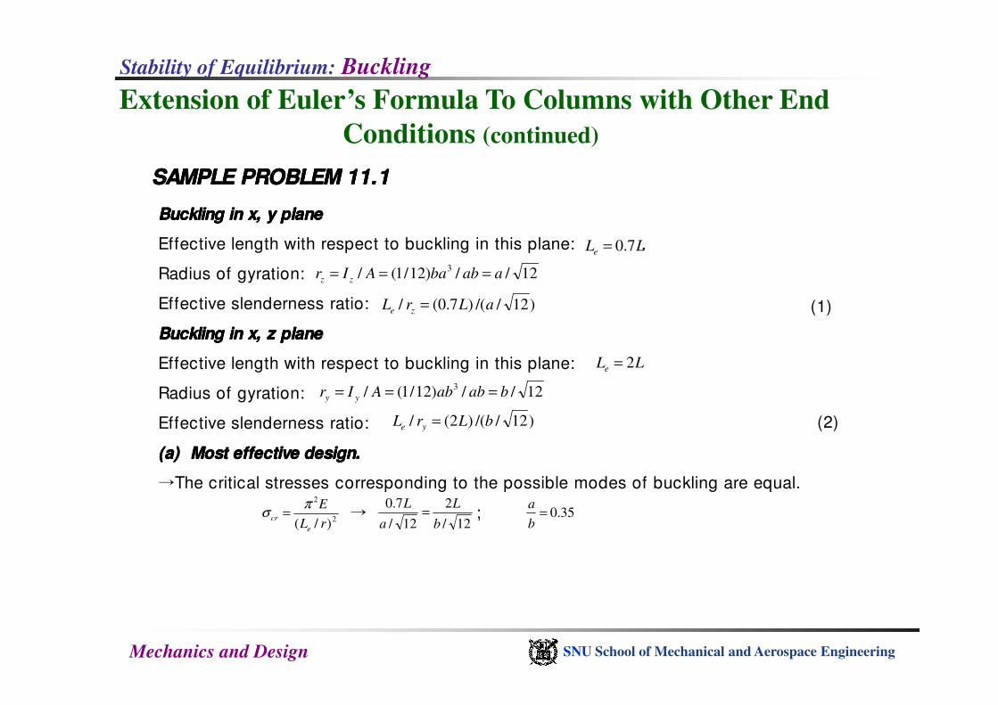
SAMPLE PROBLEM 11.1SAMPLE PROBLEM 11.1SAMPLE PROBLEM 11.1SAMPLE PROBLEM 11.1
Buckling in x, y planeBuckling in x, y planeBuckling in x, y planeBuckling in x, y plane
Effective length with respect to buckling in this plane: .
Radius of gyration:
Effective slenderness ratio:
Buckling in x, z planeBuckling in x, z planeBuckling in x, z planeBuckling in x, z plane
LLe 7.0=
12//)12/1(/ 3aabbaAIr zz ===
)12//()7.0(/ aLrL ze =
=
(1)
Mechanics and Design SNU School of Mechanical and Aerospace Engineering
Effective length with respect to buckling in this plane:
Radius of gyration:
Effective slenderness ratio:
(a)(a)(a)(a) Most effective design.Most effective design.Most effective design.Most effective design.
→The critical stresses corresponding to the possible modes of buckling are equal.
→ ;
LLe 2=
12//)12/1(/ 3bababAIr yy ===
)12//()2(/ bLrL ye =
2
2
)/( rL
E
e
cr
πσ =
12/
2
12/
7.0
b
L
a
L= 35.0=
b
a
(2)
Stability of Equilibrium: Buckling
Extension of Euler’s Formula To Columns with Other End
Conditions (continued)
Sample Problem11.1Sample Problem11.1Sample Problem11.1Sample Problem11.1
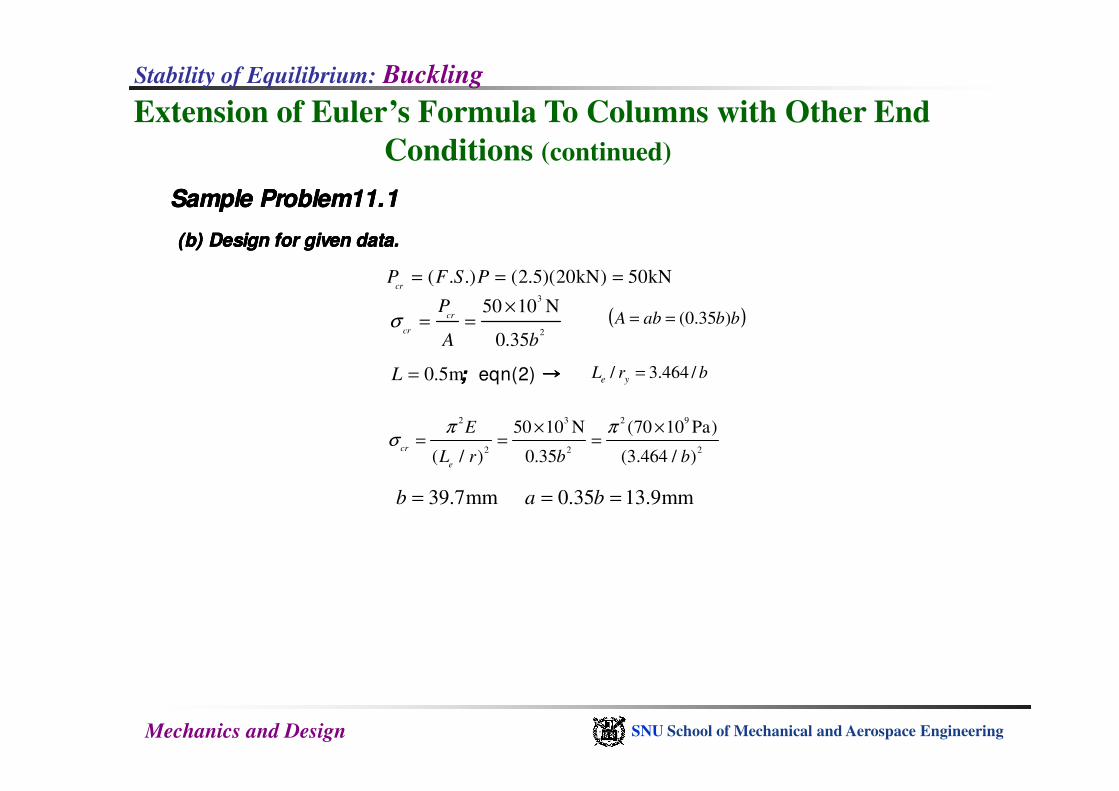
(b) Design for given data.(b) Design for given data.(b) Design for given data.(b) Design for given data.
; ; ; ; eqn(2) →→→→
( . .) (2.5)(20kN) 50kNcr
P F S P= = =
0.5mL =
3
2
50 10 N
0.35
cr
cr
P
A bσ
×= = ( )bbabA )35.0(==
brL ye /464.3/ =
Mechanics and Design SNU School of Mechanical and Aerospace Engineering
39.7mmb =
2 3 2 9
2 2 2
50 10 N (70 10 Pa)
( / ) 0.35 (3.464 / )cr
e
E
L r b b
π πσ
× ×= = =
0.35 13.9mma b= =
Stability of Equilibrium: Buckling
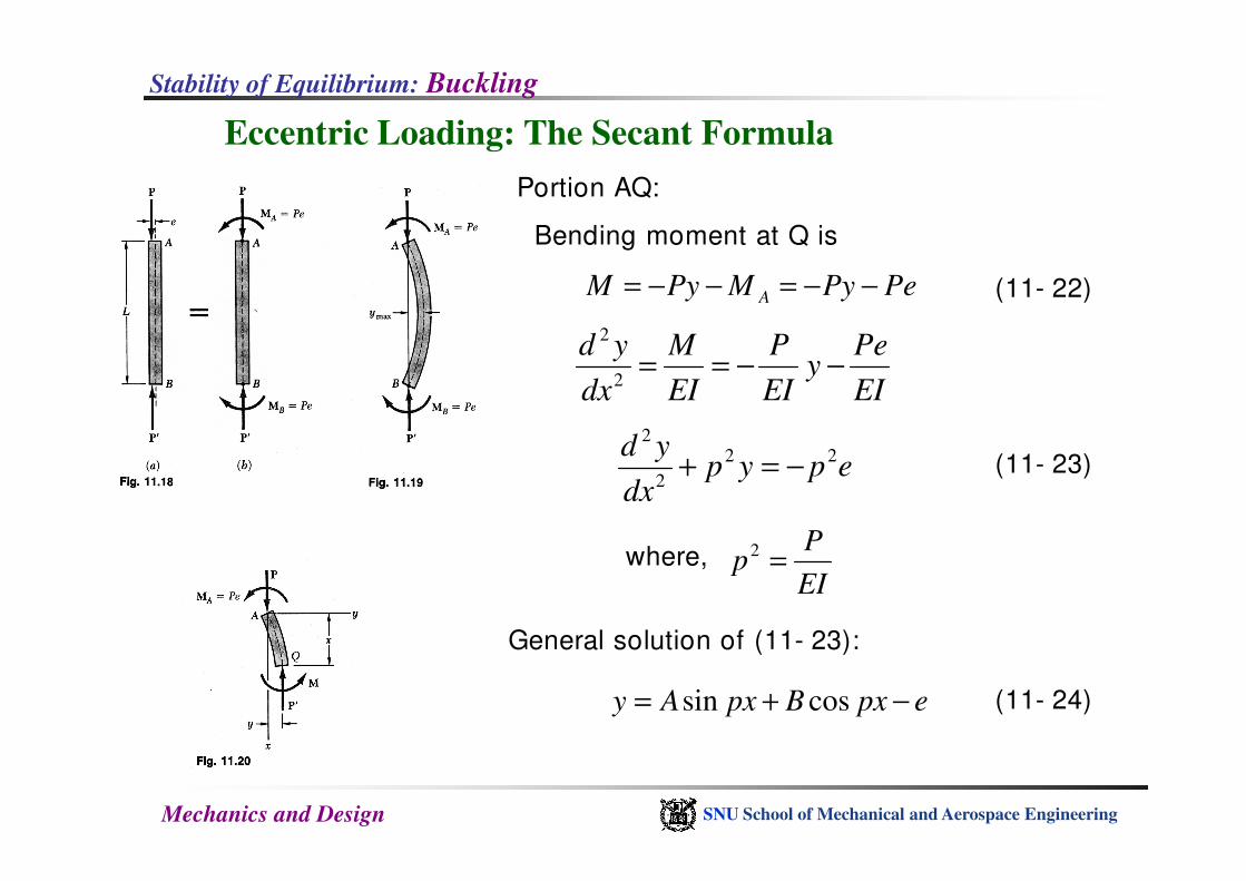
Eccentric Loading: The Secant Formula
PePyMPyM A −−=−−=
EI
Pey
EI
P
EI
M
dx
yd−−==
2
2
Portion AQ:
Bending moment at Q is
(11- 22)
yd2
Mechanics and Design SNU School of Mechanical and Aerospace Engineering
EI
Pp =2
epypdx
yd 22
2
2
−=+ (11- 23)
where,
General solution of (11- 23):
epxBpxAy −+= cossin (11- 24)
Stability of Equilibrium: Buckling
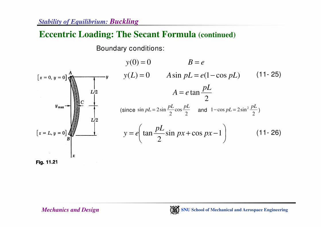
Eccentric Loading: The Secant Formula (continued)
eB =
Boundary conditions:
(11- 25)
0)0( =y
0)( =Ly )cos1(sin pLepLA −=
2cos
2sin2sin
pLpLpL =
2tan
pLeA =
2sin2cos1 2 pL
pL =−and )(since
Mechanics and Design SNU School of Mechanical and Aerospace Engineering
22 2
−+= 1cossin
2tan pxpx
pLey (11- 26)
Stability of Equilibrium: Buckling
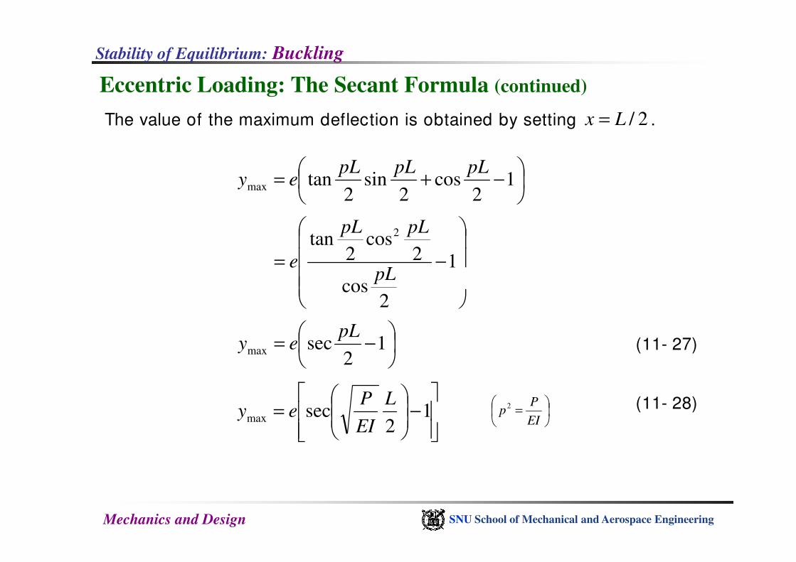
Eccentric Loading: The Secant Formula (continued)
The value of the maximum deflection is obtained by setting .2/Lx =
−+= 1
2cos
2sin
2tanmax
pLpLpLey
−= 1
cos
2cos
2tan 2
pL
pLpL
e
Mechanics and Design SNU School of Mechanical and Aerospace Engineering
=
EI
Pp
2
(11- 27)
2
cospL
−= 1
2secmax
pLey
−
= 1
2secmax
L
EI
Pey (11- 28)
Stability of Equilibrium: Buckling
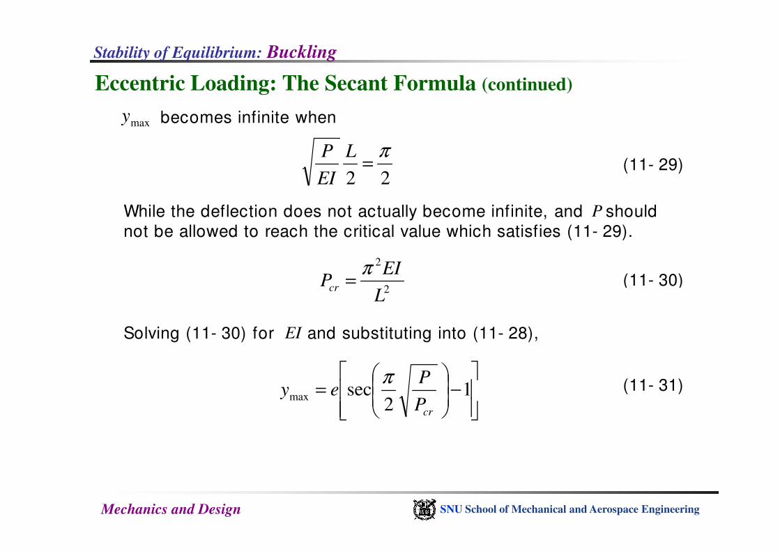
Eccentric Loading: The Secant Formula (continued)
becomes infinite when
22
π=
L
EI
P
P
(11- 30)
(11- 29)
maxy
While the deflection does not actually become infinite, and should
not be allowed to reach the critical value which satisfies (11- 29).
2EI
Pπ
=
Mechanics and Design SNU School of Mechanical and Aerospace Engineering
(11- 30)2L
EIPcr
π=
Solving (11- 30) for and substituting into (11- 28),EI
−
= 1
2secmax
crP
Pey
π (11- 31)
Stability of Equilibrium: Buckling
Eccentric Loading: The Secant Formula (continued)
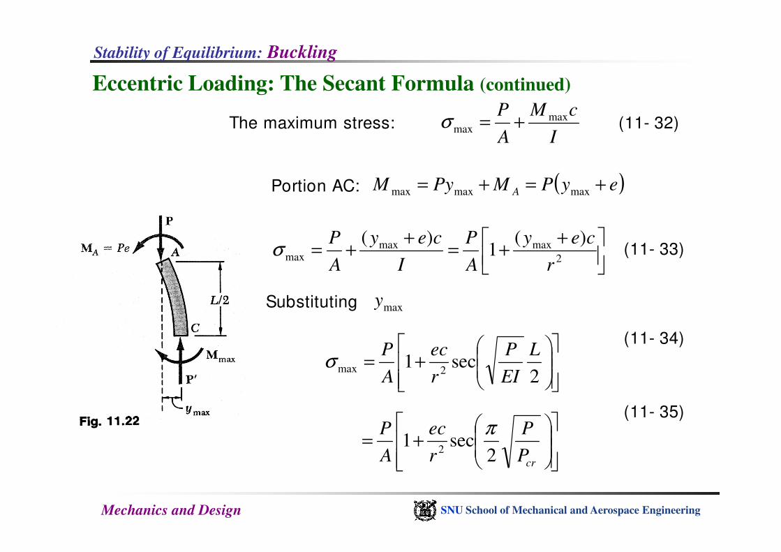
The maximum stress:
(11- 33)
(11- 32)
Portion AC:
I
cM
A
P maxmax +=σ
( )eyPMPyM A +=+= maxmaxmax
++=
++=
2
maxmaxmax
)(1
)(
r
cey
A
P
I
cey
A
Pσ
Mechanics and Design SNU School of Mechanical and Aerospace Engineering
(11- 35)
Substituting maxy
+=
2sec1
2max
L
EI
P
r
ec
A
Pσ
(11- 34)
+=
crP
P
r
ec
A
P
2sec1
2
π
Stability of Equilibrium: Buckling
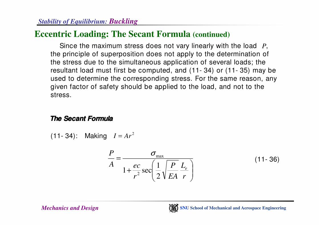
Eccentric Loading: The Secant Formula (continued)
PSince the maximum stress does not vary linearly with the load ,
the principle of superposition does not apply to the determination of
the stress due to the simultaneous application of several loads; the
resultant load must first be computed, and (11- 34) or (11- 35) may be
used to determine the corresponding stress. For the same reason, any
given factor of safety should be applied to the load, and not to the
stress.
Mechanics and Design SNU School of Mechanical and Aerospace Engineering
(11- 34): Making
(11- 36)
2ArI =
+
=
r
L
EA
P
r
ecA
P
e
2
1sec1
2
maxσ
The Secant FormulaThe Secant FormulaThe Secant FormulaThe Secant Formula
Stability of Equilibrium: Buckling
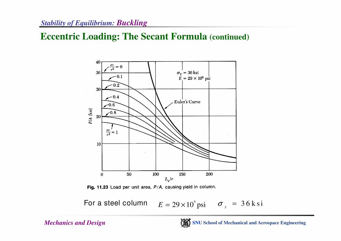
Eccentric Loading: The Secant Formula (continued)
Mechanics and Design SNU School of Mechanical and Aerospace Engineering
For a steel column 6
29 10 psiE = × 3 6 k s iY
σ =
Stability of Equilibrium: Buckling
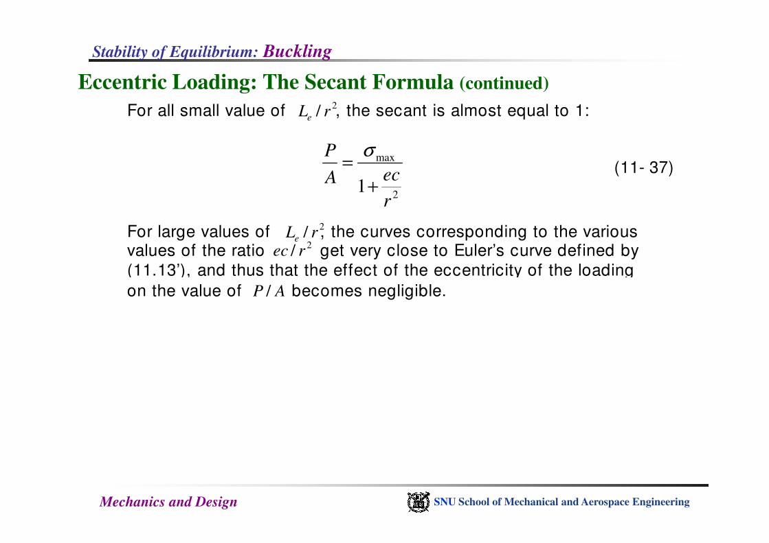
Eccentric Loading: The Secant Formula (continued)
(11- 37)
2/ rec
2
max
1r
ecA
P
+
=σ
For all small value of , the secant is almost equal to 1: 2/ rLe
For large values of , the curves corresponding to the various values of the ratio get very close to Euler’s curve defined by
(11.13’), and thus that the effect of the eccentricity of the loading
2/ rLe
Mechanics and Design SNU School of Mechanical and Aerospace Engineering
(11.13’), and thus that the effect of the eccentricity of the loading
on the value of becomes negligible.AP /
Stability of Equilibrium: Buckling
Eccentric Loading: The Secant Formula (continued)
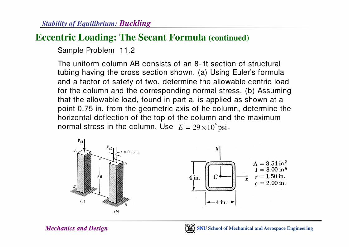
Sample Problem 11.2
The uniform column AB consists of an 8- ft section of structural tubing having the cross section shown. (a) Using Euler’s formula
and a factor of safety of two, determine the allowable centric load
for the column and the corresponding normal stress. (b) Assuming
that the allowable load, found in part a, is applied as shown at a
point 0.75 in. from the geometric axis of he column, determine the
horizontal deflection of the top of the column and the maximum
normal stress in the column. Use .6
29 10 psiE = ×
Mechanics and Design SNU School of Mechanical and Aerospace Engineering
normal stress in the column. Use .6
29 10 psiE = ×
Stability of Equilibrium: Buckling
Eccentric Loading: The Secant Formula (continued)
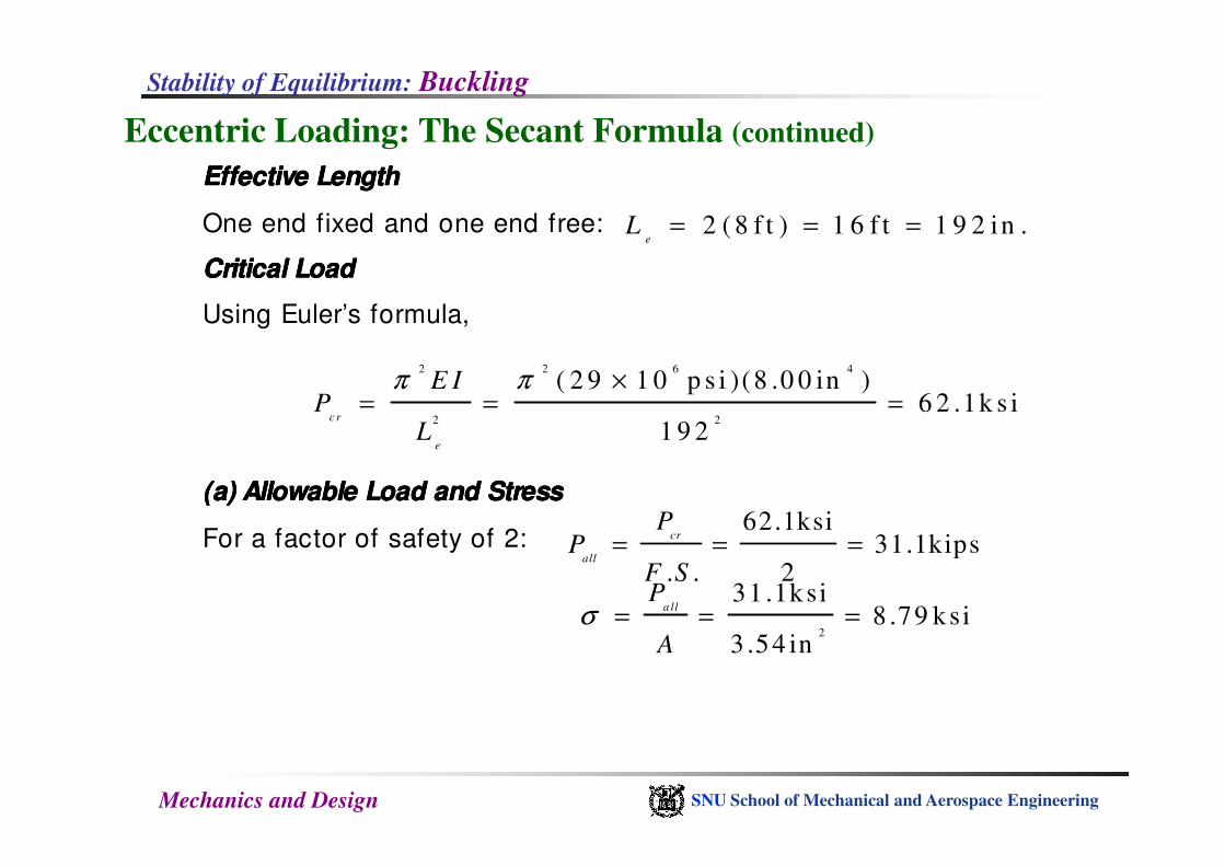
Effective LengthEffective LengthEffective LengthEffective Length
One end fixed and one end free: 2 ( 8 f t ) 1 6 f t 1 9 2 in .e
L = = =
Critical LoadCritical LoadCritical LoadCritical Load
Using Euler’s formula,
2 2 6 4
2 2
( 2 9 1 0 p s i )(8 .0 0 in )6 2 .1k s i
1 9 2c r
E IP
L
π π ×= = =
Mechanics and Design SNU School of Mechanical and Aerospace Engineering
1 9 2e
L
(a)(a)(a)(a) Allowable Load and StressAllowable Load and StressAllowable Load and StressAllowable Load and Stress
For a factor of safety of 2:62.1ksi
31.1kips. . 2
cr
all
PP
F S= = =
2
31 .1ksi8 .79 ksi
3 .54 in
a llP
Aσ = = =

Stability of Equilibrium: Buckling
Eccentric Loading: The Secant Formula (continued)
(b) Eccentric Load.(b) Eccentric Load.(b) Eccentric Load.(b) Eccentric Load.
sec 1 (0.75in) sec 1P
y eπ π
= − = −
Column AB (Fig. 1) and its loading are identical to the
upper half of the upper half of the Fig. 2.
Horizontal deflection of point A:
Mechanics and Design SNU School of Mechanical and Aerospace Engineering
maxsec 1 (0.75in) sec 1
2 2 2cr
y eP
= − = − Fig. 1Fig. 1Fig. 1Fig. 1
Fig. 2Fig. 2Fig. 2Fig. 2
0 . 9 3 9 i n=
Maximum normal stress:
max 2 2 2
31.1kips (0.75in)(2in)1 sec 1 sec
2 3.54in (1.50in) 2 2cr
P ec P
A r P
π πσ = + = +
2 2 .0 k s i=
![Impact and Postbuckling Analyses - imechanicaPostbuckling Analyses Geometric Imperfections for Postbuckling Analyses • Using buckling modes for imperfections]..](https://img.pdfslide.net/doc/110x75/5e279cdbcab01659037bd7a7/impact-and-postbuckling-analyses-imechanica-postbuckling-analyses-geometric-imperfections.jpg)