Embed Size (px)
Citation preview

November 2018 DocID029711 Rev 3 1/21
21
AN4907Application note
VL53L0X ranging module cover window guidelines
Introduction
The aim of this document is to provide guidelines for industrial design (ID) on how to assess cover window quality. It details ST’s recommendations on cover window selection and design requirements for optimizing the system.
Figure 1. VL53L0X device
www.st.com

Contents AN4907
2/21 DocID029711 Rev 3
Contents
1 Overview . . . . . . . . . . . . . . . . . . . . . . . . . . . . . . . . . . . . . . . . . . . . . . . . . . 3
2 Ideal industrial design and cover window . . . . . . . . . . . . . . . . . . . . . . . 4
2.1 ID design recommendations . . . . . . . . . . . . . . . . . . . . . . . . . . . . . . . . . . . . 5
3 VL53L0X optical paths . . . . . . . . . . . . . . . . . . . . . . . . . . . . . . . . . . . . . . . 7
3.1 Crosstalk . . . . . . . . . . . . . . . . . . . . . . . . . . . . . . . . . . . . . . . . . . . . . . . . . . 8
3.1.1 Crosstalk measurement . . . . . . . . . . . . . . . . . . . . . . . . . . . . . . . . . . . . . . 8
3.1.2 Crosstalk effect on ranging . . . . . . . . . . . . . . . . . . . . . . . . . . . . . . . . . . . 8
3.1.3 Crosstalk compensation . . . . . . . . . . . . . . . . . . . . . . . . . . . . . . . . . . . . . 8
4 Cover window optical considerations . . . . . . . . . . . . . . . . . . . . . . . . . . 10
4.1 Optical transmission . . . . . . . . . . . . . . . . . . . . . . . . . . . . . . . . . . . . . . . . . 10
4.2 Haze . . . . . . . . . . . . . . . . . . . . . . . . . . . . . . . . . . . . . . . . . . . . . . . . . . . . . 10
4.3 Cover window material . . . . . . . . . . . . . . . . . . . . . . . . . . . . . . . . . . . . . . . 10
4.4 Cover window dirt . . . . . . . . . . . . . . . . . . . . . . . . . . . . . . . . . . . . . . . . . . . 10
4.5 Cover window coating . . . . . . . . . . . . . . . . . . . . . . . . . . . . . . . . . . . . . . . .11
5 Cover window mechanical considerations . . . . . . . . . . . . . . . . . . . . . . 12
5.1 Air gap . . . . . . . . . . . . . . . . . . . . . . . . . . . . . . . . . . . . . . . . . . . . . . . . . . . 12
5.2 Cover window artwork . . . . . . . . . . . . . . . . . . . . . . . . . . . . . . . . . . . . . . . 13
5.2.1 Oval exclusion area . . . . . . . . . . . . . . . . . . . . . . . . . . . . . . . . . . . . . . . . 14
5.2.2 Two-hole exclusion area . . . . . . . . . . . . . . . . . . . . . . . . . . . . . . . . . . . . 15
6 Hornix cover window . . . . . . . . . . . . . . . . . . . . . . . . . . . . . . . . . . . . . . . 16
7 Acronyms and abbreviations . . . . . . . . . . . . . . . . . . . . . . . . . . . . . . . . . 19
8 Revision history . . . . . . . . . . . . . . . . . . . . . . . . . . . . . . . . . . . . . . . . . . . 20
DocID029711 Rev 3 3/21
AN4907 Overview
21
1 Overview
Typically the VL53L0X ranging module will be used in conjunction with a window covering. The cover window serves two main purposes:
1. Provides physical protection of the module, including dust ingress prevention.
2. To provide optical filtering for the module.
The cover window will normally be opaque with either two circular apertures or one oval aperture to allow IR light to be emitted and received.
The cover window has to fulfill some optical requirements to guarantee the ranging capabilities. The quality is measured by the transmission and haze factors.
There are also mechanical guidelines to be followed: The air gap between the VL53L0X and the cover window and the exclusion area in front of the VL53L0X.
The contributions of the optical (transmission/haze) and mechanical parameters to the device performance is given by the crosstalk measurement.
The goal is to ensure that cover window impact on VL53L0X performance is minimized.
Figure 2. VL53L0X with cover window
35° exclusion zone
25° nominal case25°

Ideal industrial design and cover window AN4907
4/21 DocID029711 Rev 3
2 Ideal industrial design and cover window
Embedded particles/holes and/or rough surfaces are major contributors to light scattering in cover windows.
An ideal cover window has:
• No structural defects in the plastic or glass material
• No surface defects that can induce light scatter or smudge sensitivity with fingerprint
• Transmission >90 % in near IR (940 nm ±10 nm) and low haze
• Outer coatings that do not degrade immunity to fingerprints (anti-fingerprint or anti-reflective coatings)
• Single material. Use of dual material may alter performance.
An ideal ID design has:
• Small air gap (<0.5 mm)
• Thin window
• Low window tilt <2 degrees
• Tight tolerances.
Figure 3. Cover window with haze
Cover window vendors are responsible for controlling cover window quality to ensure it is free of surface and structural defects.
The cover window vendor should measure the transmission of the final window and control / monitor the transmission quality in production.
Cover window vendors need to be able to measure the level of scatter (clarity or haze), which is different from transmission, as part of the transmitted light may be lost in scattering and can impact the overall system.
Cover window vendors are responsible for tolerance in material thickness.
DocID029711 Rev 3 5/21
AN4907 Ideal industrial design and cover window
21
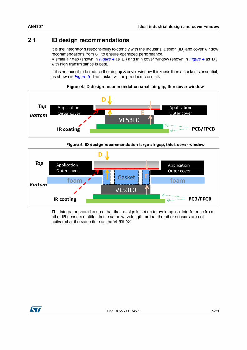
2.1 ID design recommendations
It is the integrator’s responsibility to comply with the Industrial Design (ID) and cover window recommendations from ST to ensure optimized performance. A small air gap (shown in Figure 4 as ‘E’) and thin cover window (shown in Figure 4 as ‘D’) with high transmittance is best.
If it is not possible to reduce the air gap & cover window thickness then a gasket is essential, as shown in Figure 5. The gasket will help reduce crosstalk.
Figure 4. ID design recommendation small air gap, thin cover window
Figure 5. ID design recommendation large air gap, thick cover window
The integrator should ensure that their design is set up to avoid optical interference from other IR sensors emitting in the same wavelength, or that the other sensors are not activated at the same time as the VL53L0X.
VL53L0
Top
Bottom
Application Outer cover
PCB/FPCB
D
IR coating
EApplication Outer cover
VL53L0
Top
Bottom
Application Outer cover
PCB/FPCB
D
foam
IR coating
foam Gasket E
Application Outer cover

Ideal industrial design and cover window AN4907
6/21 DocID029711 Rev 3
For optimal performance, the cover window should be parallel to VL53L0X to help reduce crosstalk and increase transmission (see Figure 6).
Figure 6. Cover window placement
VL53L0X
VL53L0X
window
window
window
VL53L0X
window

DocID029711 Rev 3 7/21
AN4907 VL53L0X optical paths
21
3 VL53L0X optical paths
Figure 7 below shows the return and noise optical paths for the light emitted from the VL53L0X, we want to minimize as much as possible the noise path.
ST’s Time-of-Flight sensors measure two key parameters to monitor window quality:
• Return signal from the object (transmission).
• Crosstalk in kcps (k counts per second) to measure cover window light scattering (haze) and light reflections below the window in the ID artwork. This also encompasses other parameters from the phone design (air gap, light reflections in the phone housing etc.).
Figure 7. VL53L0X crosstalk
Signal:
• Return - from emitter reflected off target to return array
Noise:
• Crosstalk on return array - from emitter reflected from cover window to return array

VL53L0X optical paths AN4907
8/21 DocID029711 Rev 3
3.1 Crosstalk
The crosstalk is defined as the signal from the emitter reflecting off the cover window and being sensed by the receiver (return array). The VL53L0X can tolerate and compensate for a certain amount of crosstalk, but this needs to be minimized as much as possible.
3.1.1 Crosstalk measurement
Crosstalk is measured using the entire system, VL53L0X and cover window.
Crosstalk is basically the additional amount of incoming signal when a cover window is added to the system. Once the crosstalk value is measured, the crosstalk compensation can be applied.
3.1.2 Crosstalk effect on ranging
Figure 8 shows an example of ranging data with no cover window and with very poor quality cover window. The poorer the cover window crosstalk performance is, the higher the error is compared to the ideal ranging data (green dotted line).
Figure 8. Cover window effect on ranging
3.1.3 Crosstalk compensation
Crosstalk compensation is a feature embedded in the VL53L0X firmware. It allows compensation of the crosstalk effect, based on characterization results.
The procedure for crosstalk characterization is detailed in the VL53L0X API User Manual.
Crosstalk can be compensated to a limit. The lower the crosstalk, the easier the compensation is. Figure 9 shows the crosstalk compensation capabilities of VL53L0X.

DocID029711 Rev 3 9/21
AN4907 VL53L0X optical paths
21
Figure 9. VL53L0X Crosstalk compensation capabilities

Cover window optical considerations AN4907
10/21 DocID029711 Rev 3
4 Cover window optical considerations
Two optical parameters have to be taken into consideration during the cover window selection: optical transmission and haze.
4.1 Optical transmission
The cover window has to allow through the IR light at 940nm emitted and received by the sensor.
Any loss of signal will directly affect VL53L0X performance, so we recommend to have a transmission factor as high as possible.
Between 930 and 950 nm, the cover window must have >90 % transmission
This parameter has to be provided by the cover window vendor.
4.2 Haze
Haze is a measurement of roughness, particle inclusion.
We recommend to select a window with low haze
This parameter has to be provided by the cover window vendor.
4.3 Cover window material
Cover window material can be made of glass or plastic.
It is important to note that anti-fingerprint coating increases crosstalk. We recommend to remove anti-fingerprint coating from cover window, at least in the exclusion areas defined in Section 5.2.1 and Section 5.2.2.
4.4 Cover window dirt
Smudge is the term used to describe dirt on the cover window, this can be fingerprints, grease, dust, water or anything that can be on top of cover window and can interfere with the light from the sensor.
Any protective film/coating with high surface tensile strength on top of the cover window may be considered sensitive for Time-of-Flight technology. These materials can effect optical scattering with smudge.
Not all windows will be sensitive to smudge but the impact needs to be assessed.

DocID029711 Rev 3 11/21
AN4907 Cover window optical considerations
21
The following may result in high crosstalk with smudge on window:
• ID design - if system has high crosstalk then it is likely to have more crosstalk with smudge.
• Use of some coating on the cover window (like some AFC or some Anti-Reflective coating).
• Type of window surface finishing (roughness and haze parameters).
• The window compound itself.
Or it could be the combination of the list above.
ST do not recommend the use of Anti-Reflective Coating or Anti-finger-print coating on the outer side of the cover window. It is the duty of the integrator to assess the impact of ARC or AFC on the cover window.
4.5 Cover window coating
It is important to keep the cover window surface finish smooth.
Figure 10. Glass / PMMA / Polycarbonate window (bottom view)
Rough ink Smooth ink
High Cross talk Low Cross talk

Cover window mechanical considerations AN4907
12/21 DocID029711 Rev 3
5 Cover window mechanical considerations
5.1 Air gap
As shown in Figure 11, the distance between the VL53L0X and the cover window is referred to as the air gap. The two cones on the emitter FoV are the nominal cone (25 degrees) and recommended exclusion zone (35 degrees).
Figure 11. VL53L0X with cover window: air gap and coating
As the air gap increases, the amount of crosstalk also increases.
For optimum ranging performance, the crosstalk should be kept low. Figure 12 shows an example of crosstalk variation with air gap. This figure shows that the air gap should be as small as possible in order to minimize crosstalk.
ST recommend that as well as using a high transmissible and defect free window, the basic ID design guidelines below are applied for the following usage:
• For fast and high accuracy long ranging (>1000 mm): air gap + window thickness = 1 mm maximum.
• Sub 1000 mm ranging: Total air gap + window thickness = 2 mm maximum. Assumes window thickness is <1.5 mm and air gap <0.5 mm (gasket to be fitted into air gap).
• Applications requiring short <600 mm ranging (no specific accuracy requirement) with an air gap + window thickness > 2.0 mm, a dedicated ID design study is required to optimize ranging and system performance.
For all use cases, assembly tolerances have to be accounted for in air gap + window thickness bill.
Note: The variation in the amount of crosstalk compensation required can be important if the air gap is likely to change throughout the lifetime of the system.

DocID029711 Rev 3 13/21
AN4907 Cover window mechanical considerations
21
Figure 12. Example of crosstalk variation with air gap
5.2 Cover window artwork
The customer may want for aesthetics purposes to add a coating with different optical properties compared to the cover window. The coating exclusion area has to be free from this coating.
Coating exclusion areas are defined as the area where nothing except the cover window should be present.
Production control of application assembly tolerances (X,Y,Z & tilt) are very important. Documentation is available on request from ST to calculate the minimum aperture size for a specific air gap between the VL53L0X and cover window.
The window size examples in Section 5.2.1 and Section 5.2.2 are shown with ±150 µm X/Y, ±50 µm Z-height and ±2 degree tilt assembly tolerances. For other assembly tolerances refer to ST’s hole size calculation document.
The expected performance level of an optimized cover window with 0.5 mm air gap is:
• 0.1~0.3 kcps crosstalk with PMMA embedded filtering.
• 0.3~0.7 kcps crosstalk with Gorilla Glass.
• <0.7 kcps crosstalk with PC material.
Figure 13. Oval cover window artwork
Collector and emitter hole: IR transmissive ink (regardless of color).
Everywhere else: Colored opaque paint is acceptable.

Cover window mechanical considerations AN4907
14/21 DocID029711 Rev 3
5.2.1 Oval exclusion area
Figure 14. Oval exclusion area
Table 1 gives the exclusion area at the top of the cover window (i.e. as a function of air gap + window thickness).
Table 1. Exclusion areas versus air gap + window thickness
Air gap + window thickness (mm) X (mm) (1)
1. Includes ±150 µm X/Y, ±50 µm Z-height and ±2degree tilt assembly tolerances.
Y (mm) (2)
2. Includes ±150 µm X/Y, ±50 µm Z-height and ±2degree tilt assembly tolerances.
0.1 3.81 0.81
0.2 3.88 0.88
0.3 3.95 0.95
0.4 4.02 1.02
0.5 4.09 1.09
0.6 4.16 1.16
0.7 4.23 1.23
0.8 4.30 1.30
0.9 4.37 1.37
1.0 4.44 1.44
1.5 4.68 1.68
2.0 4.99 1.99

DocID029711 Rev 3 15/21
AN4907 Cover window mechanical considerations
21
5.2.2 Two-hole exclusion area
Figure 15. Two-hole exclusion areas
Table 2 gives the exclusion areas at the top of the cover window (i.e. as a function of air gap + window thickness).
Table 2. Two hole - exclusion areas versus air gap + window thickness
Air gap + window thickness (mm)Collector diameter
(mm) (1)
1. Includes ±150 µm X/Y, ±50 µm Z-height and ±2degree tilt assembly tolerances.
Emitter diameter (mm) (2)
2. Includes ±150 µm X/Y, ±50 µm Z-height and ±2degree tilt assembly tolerances.
0.1 0.57 0.79
0.2 0.61 0.86
0.3 0.66 0.92
0.4 0.70 0.98
0.5 0.74 1.05
0.6 0.79 1.11
0.7 0.83 1.17
0.8 0.88 1.24
0.9 0.92 1.30
1.0 0.97 1.36
1.5 1.19 1.68
2.0 1.41 1.99
Hornix cover window AN4907
16/21 DocID029711 Rev 3
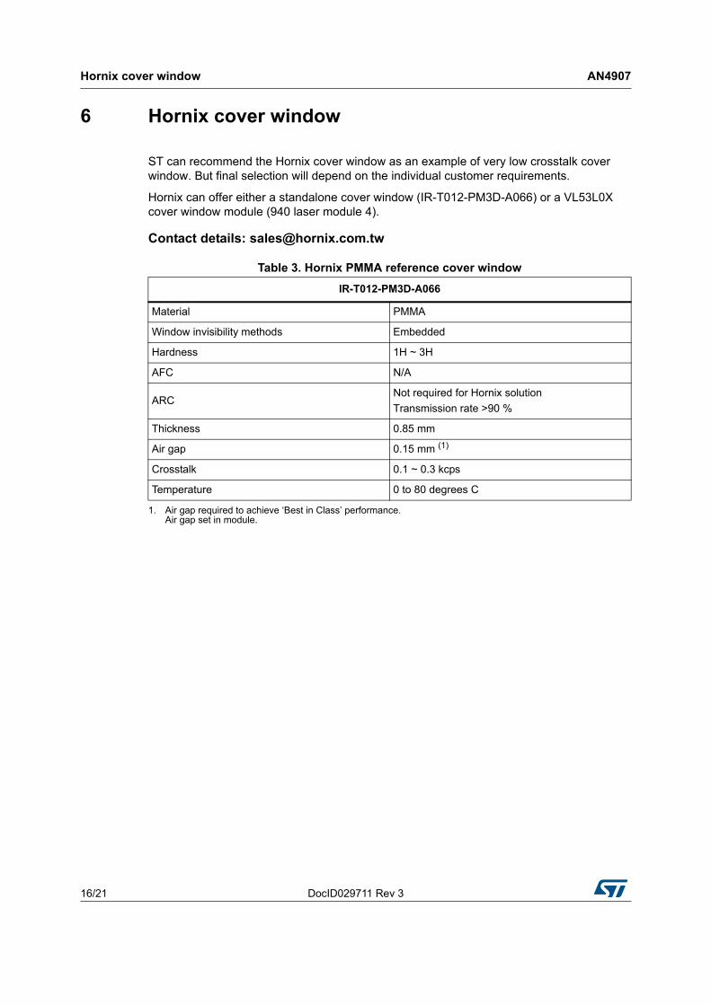
6 Hornix cover window
ST can recommend the Hornix cover window as an example of very low crosstalk cover window. But final selection will depend on the individual customer requirements.
Hornix can offer either a standalone cover window (IR-T012-PM3D-A066) or a VL53L0X cover window module (940 laser module 4).
Contact details: [email protected]
Table 3. Hornix PMMA reference cover window
IR-T012-PM3D-A066
Material PMMA
Window invisibility methods Embedded
Hardness 1H ~ 3H
AFC N/A
ARCNot required for Hornix solution
Transmission rate >90 %
Thickness 0.85 mm
Air gap 0.15 mm (1)
1. Air gap required to achieve ‘Best in Class’ performance. Air gap set in module.
Crosstalk 0.1 ~ 0.3 kcps
Temperature 0 to 80 degrees C
DocID029711 Rev 3 17/21
AN4907 Hornix cover window
21
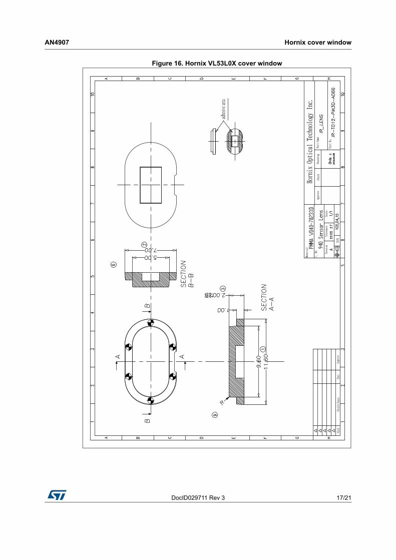
Figure 16. Hornix VL53L0X cover window

Hornix cover window AN4907
18/21 DocID029711 Rev 3
Figure 17. Hornix VL53L0X cover window module

DocID029711 Rev 3 19/21
AN4907 Acronyms and abbreviations
21
7 Acronyms and abbreviations
Table 4. Acronyms and abbreviations
Acronym/ abbreviation Definition
AFC Anti fingerprint coating
ARC Anti-reflective coating
cps Photon counts per second
ID Industrial design
IR Infrared
PC Polycarbonate
PMMA Polymethyl methacrylate
ToF Time-of-Flight
Revision history AN4907
20/21 DocID029711 Rev 3
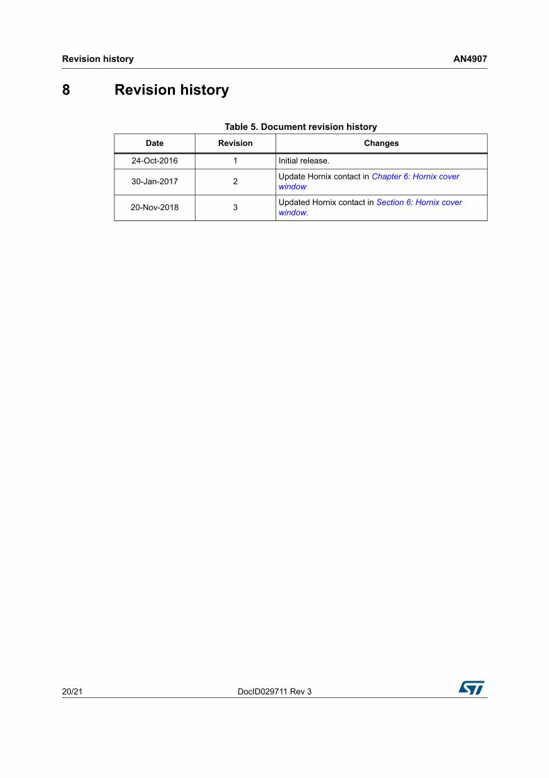
8 Revision history
Table 5. Document revision history
Date Revision Changes
24-Oct-2016 1 Initial release.
30-Jan-2017 2Update Hornix contact in Chapter 6: Hornix cover window
20-Nov-2018 3Updated Hornix contact in Section 6: Hornix cover window.

DocID029711 Rev 3 21/21
AN4907
21
IMPORTANT NOTICE – PLEASE READ CAREFULLY
STMicroelectronics NV and its subsidiaries (“ST”) reserve the right to make changes, corrections, enhancements, modifications, and improvements to ST products and/or to this document at any time without notice. Purchasers should obtain the latest relevant information on ST products before placing orders. ST products are sold pursuant to ST’s terms and conditions of sale in place at the time of order acknowledgement.
Purchasers are solely responsible for the choice, selection, and use of ST products and ST assumes no liability for application assistance or the design of Purchasers’ products.
No license, express or implied, to any intellectual property right is granted by ST herein.
Resale of ST products with provisions different from the information set forth herein shall void any warranty granted by ST for such product.
ST and the ST logo are trademarks of ST. All other product or service names are the property of their respective owners.
Information in this document supersedes and replaces information previously supplied in any prior versions of this document.
© 2018 STMicroelectronics – All rights reserved