Embed Size (px)
Citation preview
27
CHAPTER 2
Introduction to Applied Biomechanics
Understanding how the spine works requires someknowledge of mechanics and the use of clearly defined ter-minology. Biomechanics is a branch of mechanics that stud-ies structure and function within biological systems, usingmethods from mechanics. Biomechanics, like other disci-plines of mechanics, can be subdivided into the followingsubdisciplines:
• Kinematics. The study of motion, and only motion—not its causes.
• Dynamics. The study of the relationship between theaction of forces on a body and the motion of thatbody. Dynamics can, in turn, be subdivided into thefollowing two fields:
s Statics. The study of bodies at rest. The sum offorces is zero, so no motion occurs. In other words,equilibrium.
s Kinetics. The study of bodies in motion in relationto the forces acting on them.
Within mechanics, a distinction is made between solidand fluid mechanics. Both are often combined in the body.Solid mechanics is involved in the loading on a joint; fluidmechanics in the lubrication of that joint. In the context ofthis book, we limit ourselves to solid mechanics. To under-stand this aspect of mechanics properly, it is of the utmostimportance to clearly define the terminology used.
Scalar. A quantity that has only magnitude—temperature,for example.
Vector. A quantity determined and characterized by bothmagnitude and direction—a speed or a force, for exam-
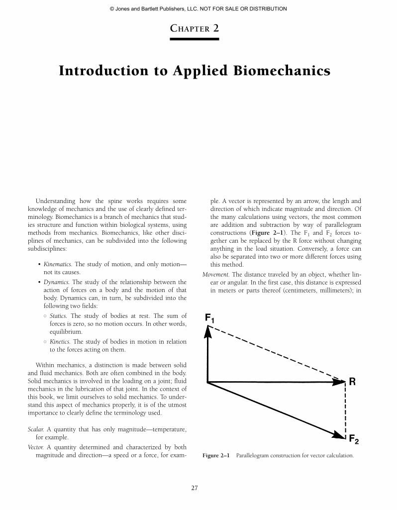
ple. A vector is represented by an arrow, the length anddirection of which indicate magnitude and direction. Ofthe many calculations using vectors, the most commonare addition and subtraction by way of parallelogramconstructions (Figure 2–1). The F1 and F2 forces to-gether can be replaced by the R force without changinganything in the load situation. Conversely, a force canalso be separated into two or more different forces usingthis method.
Movement. The distance traveled by an object, whether lin-ear or angular. In the first case, this distance is expressedin meters or parts thereof (centimeters, millimeters); in
Figure 2–1 Parallelogram construction for vector calculation.
55942_CH02_Vander.qxd 2/7/09 9:37 AM Page 27
© Jones and Bartlett Publishers, LLC. NOT FOR SALE OR DISTRIBUTION
28 2 INTRODUCTION TO APPLIED BIOMECHANICS
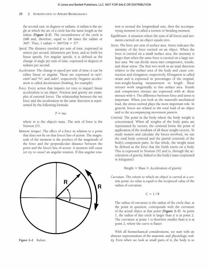
the second case, in degrees or radians. A radian is the an-gle at which the arc of a circle has the same length as theradius (Figure 2–2). The circumference of the circle is2pR and, therefore, equal to 2p times the radian or360°. Thus, 1 radian 5 360º/2p 5 57º.
Speed. The distance traveled per unit of time, expressed inmeters per second, kilometers per hour, and so forth forlinear speeds. For angular speeds, it is defined as thechange of angle per unit of time, expressed in degrees orradians per second.
Acceleration. The change in speed per unit of time; it can beeither linear or angular. These are expressed in m/s2,cm/s2 and º/s2, and rad/s2, respectively. Negative acceler-ation is called deceleration (braking, for example).
Force. Every action that imparts (or tries to impart) linearacceleration to an object. Friction and gravity are exam-ples of external forces. The relationship between the netforce and the acceleration in the same direction is repre-sented by the following formula:
F 5 ma
where m is the object’s mass. The unit of force is theNewton (N).
Moment (torque). The effect of a force in relation to a pointthat does not lie on that force’s line of action. The magni-tude of the moment is the product of the magnitude ofthe force and the perpendicular distance between thepoint and the force’s line of action. A moment will cause(or try to cause) an angular rotation. If this angular rota-
tion is around the longitudinal axis, then the accompa-nying moment is called a torsion or bending moment.
Equilibrium. A situation where the sum of all forces and mo-ments exerted on an object equals zero.
Stress. The force per unit of surface area. Stress indicates theintensity of the force exerted on an object. When theforce is exerted on a small surface area, the intensity islarger than when the same force is exerted on a large sur-face area. We can divide stress into compressive, tensile,and shear stress. The first two work in an axial directionrelative to the surface area of the body and cause con-traction and elongation, respectively. Elongation is calledstrain and is expressed in percentages of the original,non-weight-bearing measurement or length. Shearstresses work tangentially to this surface area. Tensileand compressive stresses are expressed with s; shearstresses with t. The difference between force and stress isimportant. When you look at the material’s mechanicalload, the stress exerted plays the most important role. Ingeneral, forces are related to the total load of an objectand to the accompanying movement pattern.
Centroid. The point in the body where the body weight isconcentrated. When all weights of the body parts arerepresented by vectors, the centroid forms the point ofapplication of the resultant of all these weight vectors. Tostudy motion and calculate the forces involved, we usethe total body centroid and the partial centroids of thebody’s component parts. In this whole, the weight mustbe defined as the force that the Earth exerts on a body.This is expressed in Newton (N) and is, through the ac-celeration of gravity, linked to the body’s mass (expressedin kilograms):
Weight 5 Mass 3 Acceleration of gravity
Curvature. The extent to which an object is curved at a cer-tain point; its value is equal to the reciprocal value of theradius of curvature:
C 5 1 / R
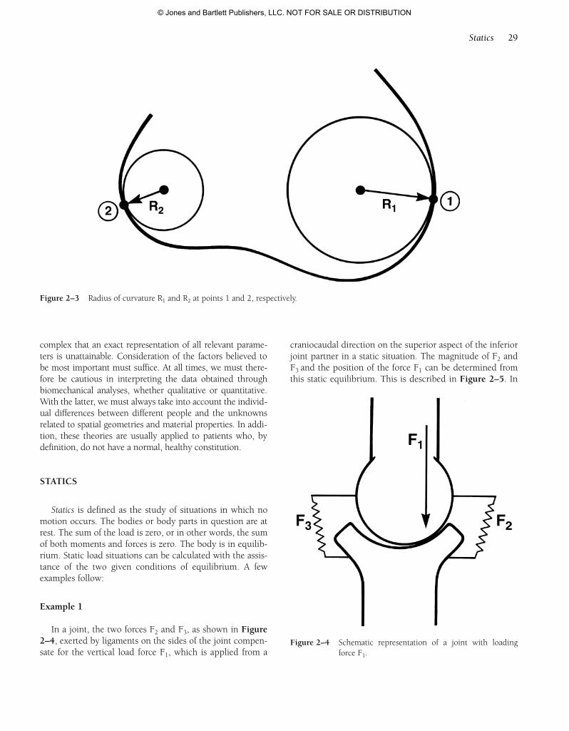
The radius of curvature is the radius of the circle that, atthe point in question, corresponds with the curvature of the actual object at that point (Figure 2–3). At point1, the radius of this circle is larger than it is at point 2.The curvature at point 1 is therefore smaller than it is atpoint 2, where the curve is flatter.
With all biomechanical considerations, we start with anabstract representation of the anatomic and physiologic real-ity. Even when we look at small parts of it, the body is soFigure 2–2 Radian.
55942_CH02_Vander.qxd 2/7/09 9:37 AM Page 28
© Jones and Bartlett Publishers, LLC. NOT FOR SALE OR DISTRIBUTION
complex that an exact representation of all relevant parame-ters is unattainable. Consideration of the factors believed tobe most important must suffice. At all times, we must there-fore be cautious in interpreting the data obtained throughbiomechanical analyses, whether qualitative or quantitative.With the latter, we must always take into account the individ-ual differences between different people and the unknownsrelated to spatial geometries and material properties. In addi-tion, these theories are usually applied to patients who, bydefinition, do not have a normal, healthy constitution.
STATICS
Statics is defined as the study of situations in which nomotion occurs. The bodies or body parts in question are atrest. The sum of the load is zero, or in other words, the sumof both moments and forces is zero. The body is in equilib-rium. Static load situations can be calculated with the assis-tance of the two given conditions of equilibrium. A fewexamples follow:
Example 1
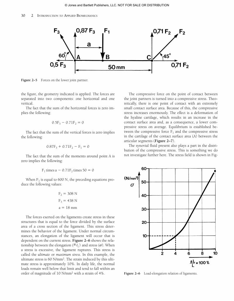
In a joint, the two forces F2 and F3, as shown in Figure2–4, exerted by ligaments on the sides of the joint compen-sate for the vertical load force F1, which is applied from a
craniocaudal direction on the superior aspect of the inferiorjoint partner in a static situation. The magnitude of F2 andF3 and the position of the force F1 can be determined fromthis static equilibrium. This is described in Figure 2–5. In
Statics 29
Figure 2–3 Radius of curvature R1 and R2 at points 1 and 2, respectively.
Figure 2–4 Schematic representation of a joint with loadingforce F1.
55942_CH02_Vander.qxd 2/7/09 9:37 AM Page 29
© Jones and Bartlett Publishers, LLC. NOT FOR SALE OR DISTRIBUTION
the figure, the geometry indicated is applied. The forces areseparated into two components: one horizontal and onevertical.
The fact that the sum of the horizontal forces is zero im-plies the following:
0.5F3 2 0.71F2 5 0
The fact that the sum of the vertical forces is zero impliesthe following:
0.87F3 1 0.71F2 2 F1 5 0
The fact that the sum of the moments around point A iszero implies the following:
F1 times a 2 0.71F2 times 50 5 0
When F1 is equal to 600 N, the preceding equations pro-duce the following values:
F2 5 308 N
F3 5 438 N
a 5 18 mm
The forces exerted on the ligaments create stress in thesestructures that is equal to the force divided by the surfacearea of a cross section of the ligament. This stress deter-mines the behavior of the ligament. Under normal circum-stances, an elongation of the ligament will occur that isdependent on the current stress. Figure 2–6 shows the rela-tionship between the elongation (DL/L) and stress (s). Whena stress is excessive, the ligament ruptures. This stress iscalled the ultimate or maximum stress. In this example, theultimate stress is 60 N/mm2. The strain induced by this ulti-mate stress is approximately 10%. In daily life, the normalloads remain well below that limit and tend to fall within anorder of magnitude of 10 N/mm2 with a strain of 4%.
The compressive force on the point of contact betweenthe joint partners is turned into a compressive stress. Theo-retically, there is one point of contact with an extremelysmall contact surface area. Because of this, the compressivestress increases enormously. The effect is a deformation ofthe hyaline cartilage, which results in an increase in thecontact surface area and, as a consequence, a lower com-pressive stress on average. Equilibrium is established be-tween the compressive force F1 and the compressive stressin the cartilage of the contact surface area (A) between thearticular segments (Figure 2–7).
The synovial fluid present also plays a part in the distri-bution of the compressive stress. This is something we donot investigate further here. The stress field is shown in Fig-
30 2 INTRODUCTION TO APPLIED BIOMECHANICS
Figure 2–5 Forces on the lower joint partner.
Figure 2–6 Load-elongation relation of ligaments.
55942_CH02_Vander.qxd 2/7/09 9:37 AM Page 30
© Jones and Bartlett Publishers, LLC. NOT FOR SALE OR DISTRIBUTION
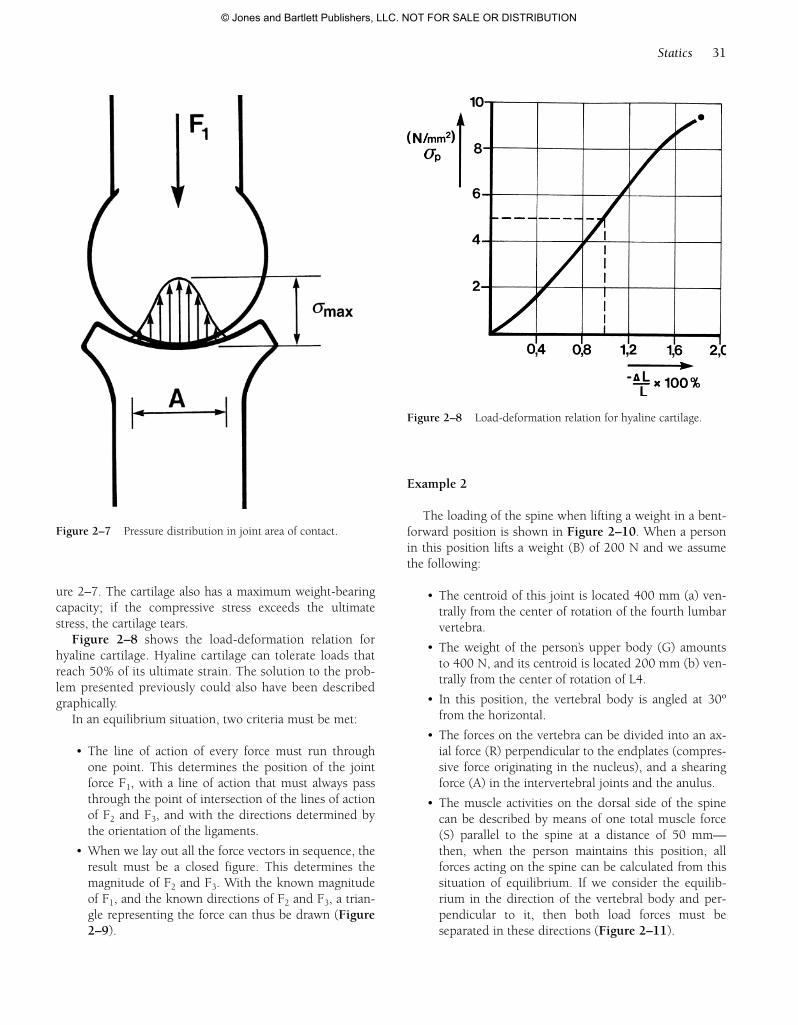
ure 2–7. The cartilage also has a maximum weight-bearingcapacity; if the compressive stress exceeds the ultimatestress, the cartilage tears.
Figure 2–8 shows the load-deformation relation forhyaline cartilage. Hyaline cartilage can tolerate loads thatreach 50% of its ultimate strain. The solution to the prob-lem presented previously could also have been describedgraphically.
In an equilibrium situation, two criteria must be met:
• The line of action of every force must run throughone point. This determines the position of the jointforce F1, with a line of action that must always passthrough the point of intersection of the lines of actionof F2 and F3, and with the directions determined bythe orientation of the ligaments.
• When we lay out all the force vectors in sequence, theresult must be a closed figure. This determines themagnitude of F2 and F3. With the known magnitudeof F1, and the known directions of F2 and F3, a trian-gle representing the force can thus be drawn (Figure2–9).
Example 2
The loading of the spine when lifting a weight in a bent-forward position is shown in Figure 2–10. When a personin this position lifts a weight (B) of 200 N and we assumethe following:
• The centroid of this joint is located 400 mm (a) ven-trally from the center of rotation of the fourth lumbarvertebra.
• The weight of the person’s upper body (G) amountsto 400 N, and its centroid is located 200 mm (b) ven-trally from the center of rotation of L4.
• In this position, the vertebral body is angled at 30ºfrom the horizontal.
• The forces on the vertebra can be divided into an ax-ial force (R) perpendicular to the endplates (compres-sive force originating in the nucleus), and a shearingforce (A) in the intervertebral joints and the anulus.
• The muscle activities on the dorsal side of the spinecan be described by means of one total muscle force(S) parallel to the spine at a distance of 50 mm—then, when the person maintains this position, allforces acting on the spine can be calculated from thissituation of equilibrium. If we consider the equilib-rium in the direction of the vertebral body and per-pendicular to it, then both load forces must beseparated in these directions (Figure 2–11).
Statics 31
Figure 2–8 Load-deformation relation for hyaline cartilage.
Figure 2–7 Pressure distribution in joint area of contact.
55942_CH02_Vander.qxd 2/7/09 9:37 AM Page 31
© Jones and Bartlett Publishers, LLC. NOT FOR SALE OR DISTRIBUTION
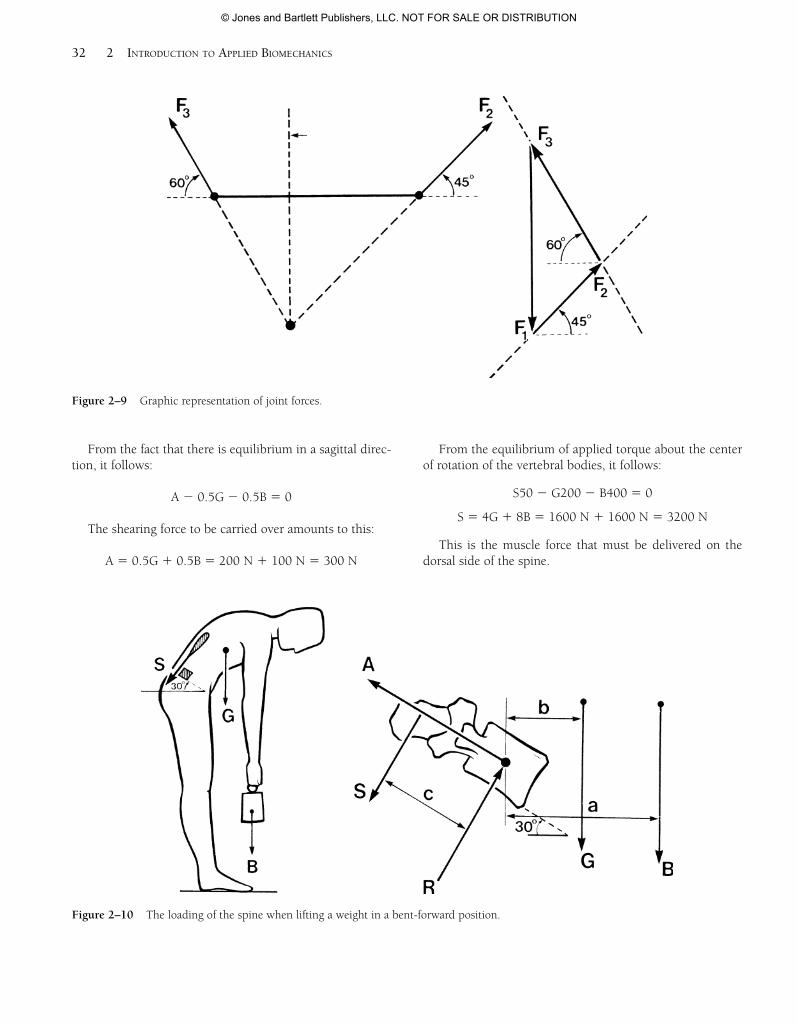
From the fact that there is equilibrium in a sagittal direc-tion, it follows:
A 2 0.5G 2 0.5B 5 0
The shearing force to be carried over amounts to this:
A 5 0.5G 1 0.5B 5 200 N 1 100 N 5 300 N
From the equilibrium of applied torque about the centerof rotation of the vertebral bodies, it follows:
S50 2 G200 2 B400 5 0
S 5 4G 1 8B 5 1600 N 1 1600 N 5 3200 N
This is the muscle force that must be delivered on thedorsal side of the spine.
32 2 INTRODUCTION TO APPLIED BIOMECHANICS
Figure 2–10 The loading of the spine when lifting a weight in a bent-forward position.
Figure 2–9 Graphic representation of joint forces.
55942_CH02_Vander.qxd 2/7/09 9:37 AM Page 32
© Jones and Bartlett Publishers, LLC. NOT FOR SALE OR DISTRIBUTION
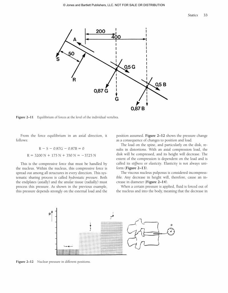
From the force equilibrium in an axial direction, it follows:
R 2 S 2 0.87G 2 0.87B 5 0
R 5 3200 N 1 175 N 1 350 N 5 23725 N
This is the compressive force that must be handled bythe nucleus. Within the nucleus, this compressive force isspread out among all structures in every direction. This sys-tematic sharing process is called hydrostatic pressure. Boththe endplates (axially) and the anular tissue (radially) mustprocess this pressure. As shown in the previous example,this pressure depends strongly on the external load and the
position assumed. Figure 2–12 shows the pressure changeas a consequence of changes to position and load.
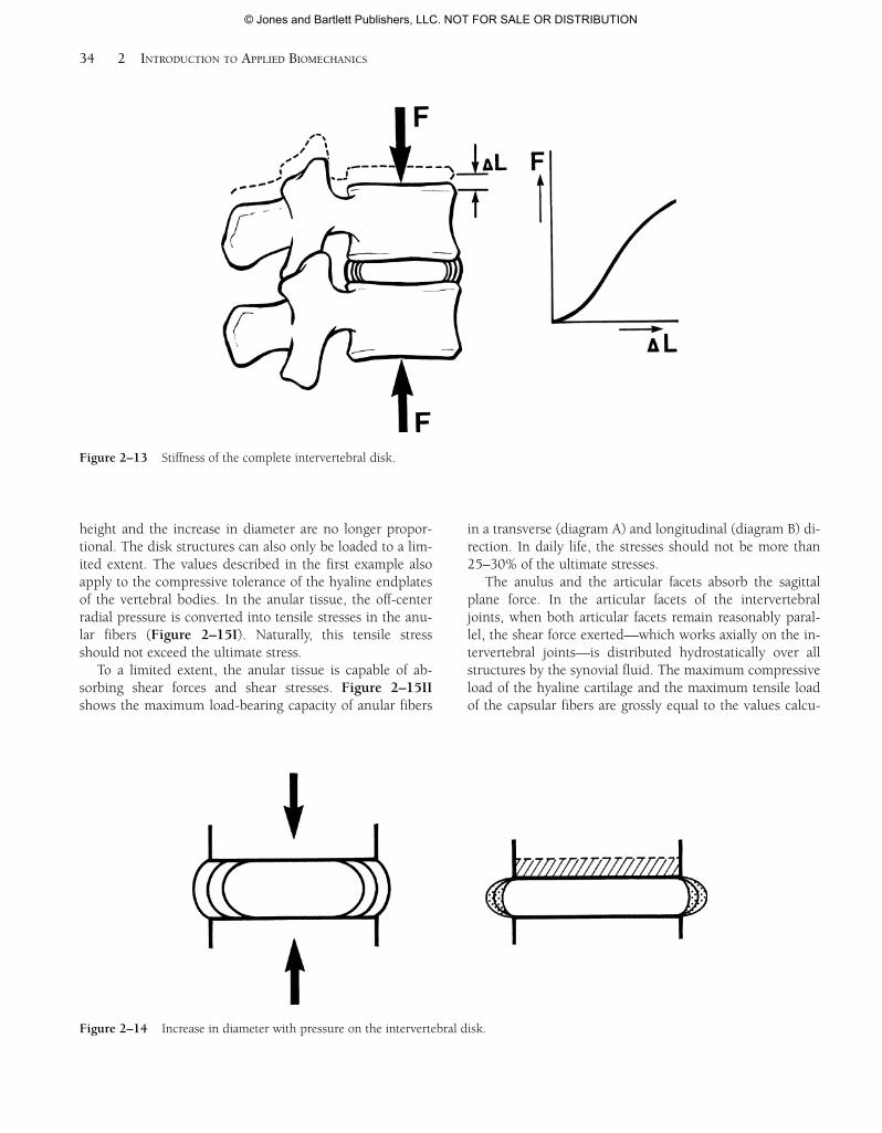
The load on the spine, and particularly on the disk, re-sults in distortions. With an axial compression load, thedisk will be compressed, and its height will decrease. Theextent of the compression is dependent on the load and iscalled its stiffness or elasticity. Elasticity is not always uni-form (Figure 2–13).
The viscous nucleus pulposus is considered incompress-ible. Any decrease in height will, therefore, cause an in-crease in diameter (Figure 2–14).
When a certain pressure is applied, fluid is forced out ofthe nucleus and into the body, meaning that the decrease in
Statics 33
Figure 2–11 Equilibrium of forces at the level of the individual vertebra.
Figure 2–12 Nuclear pressure in different positions.
55942_CH02_Vander.qxd 2/7/09 9:37 AM Page 33
© Jones and Bartlett Publishers, LLC. NOT FOR SALE OR DISTRIBUTION
34 2 INTRODUCTION TO APPLIED BIOMECHANICS
Figure 2–13 Stiffness of the complete intervertebral disk.
Figure 2–14 Increase in diameter with pressure on the intervertebral disk.
height and the increase in diameter are no longer propor-tional. The disk structures can also only be loaded to a lim-ited extent. The values described in the first example alsoapply to the compressive tolerance of the hyaline endplatesof the vertebral bodies. In the anular tissue, the off-centerradial pressure is converted into tensile stresses in the anu-lar fibers (Figure 2–15I). Naturally, this tensile stressshould not exceed the ultimate stress.
To a limited extent, the anular tissue is capable of ab-sorbing shear forces and shear stresses. Figure 2–15IIshows the maximum load-bearing capacity of anular fibers
in a transverse (diagram A) and longitudinal (diagram B) di-rection. In daily life, the stresses should not be more than25–30% of the ultimate stresses.
The anulus and the articular facets absorb the sagittalplane force. In the articular facets of the intervertebraljoints, when both articular facets remain reasonably paral-lel, the shear force exerted—which works axially on the in-tervertebral joints—is distributed hydrostatically over allstructures by the synovial fluid. The maximum compressiveload of the hyaline cartilage and the maximum tensile loadof the capsular fibers are grossly equal to the values calcu-
55942_CH02_Vander.qxd 2/7/09 9:37 AM Page 34
© Jones and Bartlett Publishers, LLC. NOT FOR SALE OR DISTRIBUTION
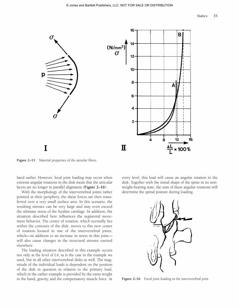
lated earlier. However, focal joint loading may occur whenextreme angular rotations in the disk mean that the articularfacets are no longer in parallel alignment (Figure 2–16).
With the morphology of the intervertebral joints ratherpointed at their periphery, the shear forces are then trans-ferred over a very small surface area. In this scenario, theresulting stresses can be very large and may even exceedthe ultimate stress of the hyaline cartilage. In addition, thesituation described here influences the segmental move-ment behavior. The center of rotation, which normally lieswithin the contours of the disk, moves to this new centerof rotation located in one of the intervertebral joints,which—in addition to an increase in stress in this joint—will also cause changes in the structural stresses exertedelsewhere.
The loading situation described in this example occursnot only at the level of L4, as is the case in the example weused, but in all other intervertebral disks as well. The mag-nitude of the individual loads is dependent on the positionof the disk in question in relation to the primary load,which in the earlier example is provided by the extra weightin the hand, gravity, and the compensatory muscle force. At
Statics 35
Figure 2–15 Material properties of the annular fibers.
Figure 2–16 Focal joint loading in the intervertebral joint.
every level, this load will cause an angular rotation in thedisk. Together with the initial shape of the spine in its non-weight-bearing state, the sum of these angular rotations willdetermine the spinal posture during loading.
55942_CH02_Vander.qxd 2/7/09 9:37 AM Page 35
© Jones and Bartlett Publishers, LLC. NOT FOR SALE OR DISTRIBUTION
Mathematically, this posture can best be expressed interms of its curvature because in the sagittal and frontalplanes, that is, when the spine is bent, a mathematical rela-tion exists between this curvature (C) and the accompany-ing load, namely:
DC 5 M / EI
The change in curvature (DC) is the ratio between theresultant flexion torque M and the bending stiffness of EI.This bending stiffness can be seen as the resistance to bend-ing. With a specific flexion torque, only a slight curvaturewill occur when this EI is large. This bending stiffness con-sists of two components:
E: The modulus of elasticity. For industrial-grade materials,the modulus of elasticity is fixed. For a complex, com-posite, nonlinear structure such as the intervertebraljoint, it is an average of all elasticity moduli of the vari-ous structures, which is, moreover, dependent on theamount of loading and the speed with which the loadinghas taken place.
I: The surface area moment of inertia determined by the cross-sectional measurements.
Taking into account the relationship mentioned previ-ously, we can also learn more about the loading of the
spine by studying its shape with methods such as X-raysand outline photos, which can then be described mathe-matically. This description of its shape can be optimizedusing known mathematical techniques, and the curvaturescan be calculated. When additional facts are known aboutthe bending stiffness of the spine, we can better under-stand the loading.
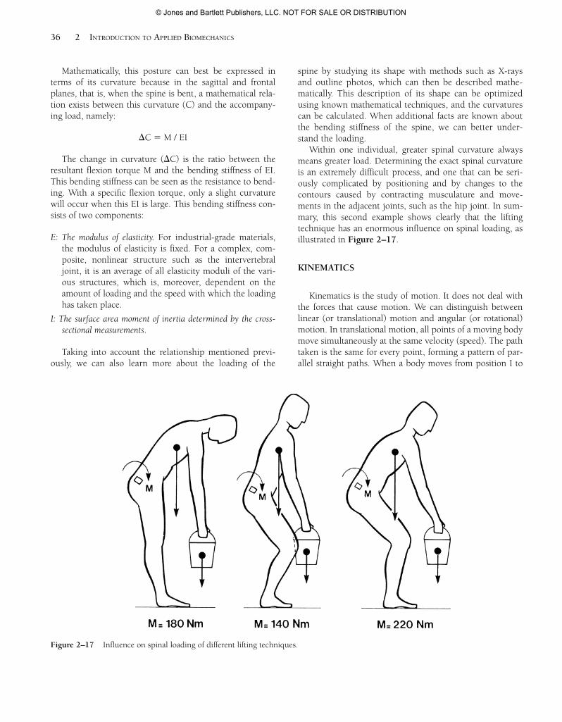
Within one individual, greater spinal curvature alwaysmeans greater load. Determining the exact spinal curvatureis an extremely difficult process, and one that can be seri-ously complicated by positioning and by changes to thecontours caused by contracting musculature and move-ments in the adjacent joints, such as the hip joint. In sum-mary, this second example shows clearly that the liftingtechnique has an enormous influence on spinal loading, asillustrated in Figure 2–17.
KINEMATICS
Kinematics is the study of motion. It does not deal withthe forces that cause motion. We can distinguish betweenlinear (or translational) motion and angular (or rotational)motion. In translational motion, all points of a moving bodymove simultaneously at the same velocity (speed). The pathtaken is the same for every point, forming a pattern of par-allel straight paths. When a body moves from position I to
36 2 INTRODUCTION TO APPLIED BIOMECHANICS
Figure 2–17 Influence on spinal loading of different lifting techniques.
55942_CH02_Vander.qxd 2/7/09 9:37 AM Page 36
© Jones and Bartlett Publishers, LLC. NOT FOR SALE OR DISTRIBUTION
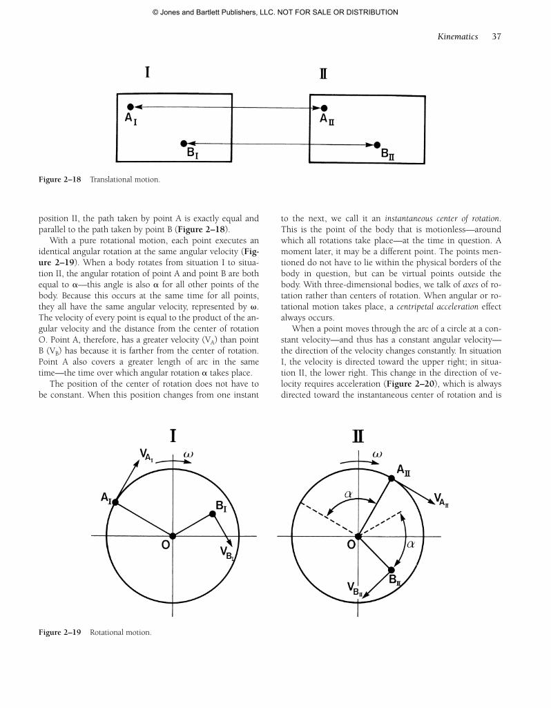
position II, the path taken by point A is exactly equal andparallel to the path taken by point B (Figure 2–18).
With a pure rotational motion, each point executes anidentical angular rotation at the same angular velocity (Fig-ure 2–19). When a body rotates from situation I to situa-tion II, the angular rotation of point A and point B are bothequal to a—this angle is also a for all other points of thebody. Because this occurs at the same time for all points,they all have the same angular velocity, represented by v.The velocity of every point is equal to the product of the an-gular velocity and the distance from the center of rotationO. Point A, therefore, has a greater velocity (VA) than pointB (VB) has because it is farther from the center of rotation.Point A also covers a greater length of arc in the sametime—the time over which angular rotation a takes place.
The position of the center of rotation does not have tobe constant. When this position changes from one instant
to the next, we call it an instantaneous center of rotation.This is the point of the body that is motionless—aroundwhich all rotations take place—at the time in question. Amoment later, it may be a different point. The points men-tioned do not have to lie within the physical borders of thebody in question, but can be virtual points outside thebody. With three-dimensional bodies, we talk of axes of ro-tation rather than centers of rotation. When angular or ro-tational motion takes place, a centripetal acceleration effectalways occurs.
When a point moves through the arc of a circle at a con-stant velocity—and thus has a constant angular velocity—the direction of the velocity changes constantly. In situationI, the velocity is directed toward the upper right; in situa-tion II, the lower right. This change in the direction of ve-locity requires acceleration (Figure 2–20), which is alwaysdirected toward the instantaneous center of rotation and is
Kinematics 37
Figure 2–18 Translational motion.
Figure 2–19 Rotational motion.
55942_CH02_Vander.qxd 2/7/09 9:37 AM Page 37
© Jones and Bartlett Publishers, LLC. NOT FOR SALE OR DISTRIBUTION
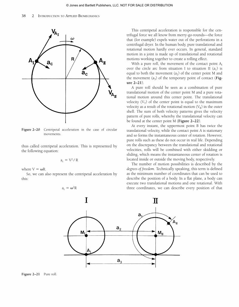
thus called centripetal acceleration. This is represented bythe following equation:
ac 5 V2 / R
where V 5 vR.So, we can also represent the centripetal acceleration by
this:
ac 5 v2R
This centripetal acceleration is responsible for the cen-trifugal force we all know from merry-go-rounds—the forcethat (for example) expels water out of the perforations in acentrifugal dryer. In the human body, pure translational androtational motion hardly ever occurs. In general, standardmotion in a joint is made up of translational and rotationalmotions working together to create a rolling effect.
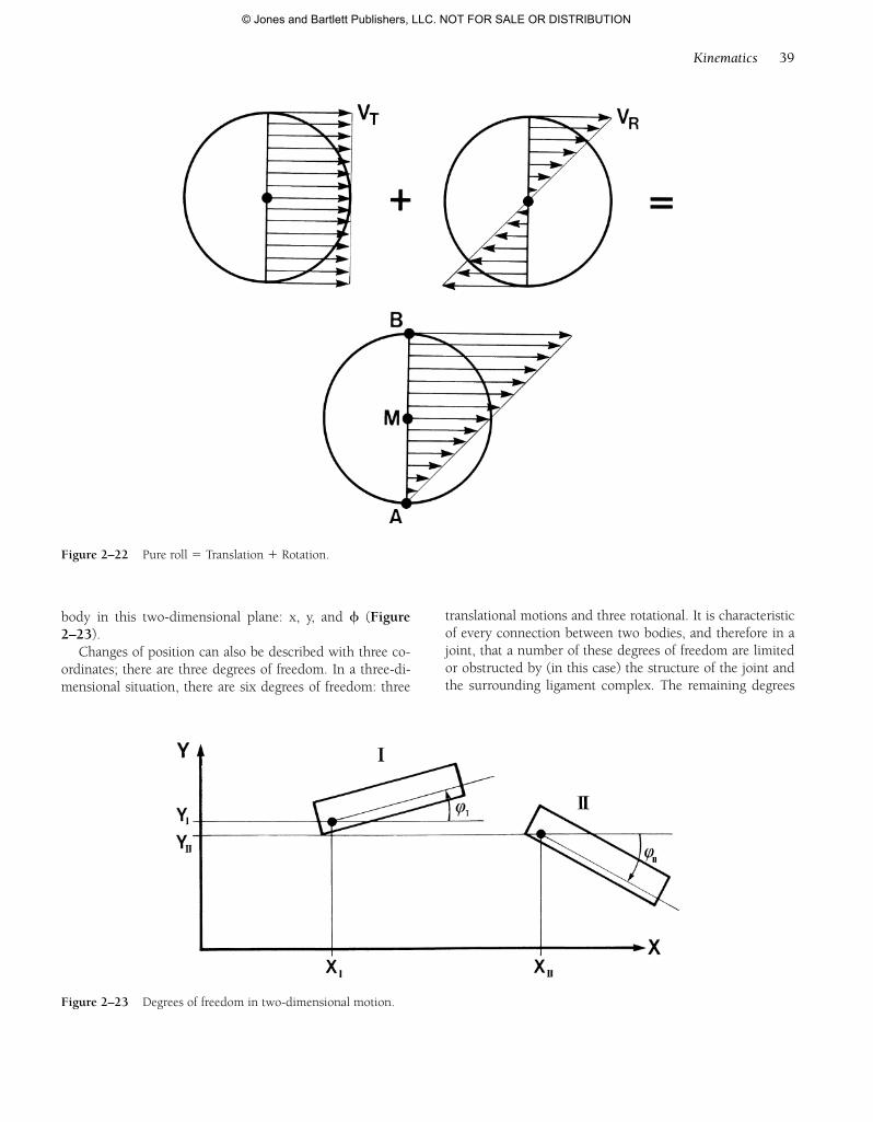
With a pure roll, the movement of the contact point AI
over the circle arc from situation I to situation II (a1) isequal to both the movement (a2) of the center point M andthe movement (a3) of the temporary point of contact (Fig-ure 2–21).
A pure roll should be seen as a combination of puretranslational motion of the center point M and a pure rota-tional motion around this center point. The translationalvelocity (VT) of the center point is equal to the maximumvelocity as a result of the rotational motion (VR) in the outershell. The sum of both velocity patterns gives the velocitypattern of pure rolls, whereby the translational velocity canbe found at the center point M (Figure 2–22).
At every instant, the uppermost point B has twice thetranslational velocity, while the contact point A is stationaryand so forms the instantaneous center of rotation. However,pure rolls such as these do not occur in real life. Dependingon the discrepancy between the translational and rotationalvelocities, rolls will be combined with either skidding orsliding, which means the instantaneous center of rotation islocated inside or outside the moving body, respectively.
The number of motion possibilities is described by thedegrees of freedom. Technically speaking, this term is definedas the minimum number of coordinates that can be used todescribe the position of a body. In a flat plane, a body canexecute two translational motions and one rotational. Withthree coordinates, we can describe every position of that
38 2 INTRODUCTION TO APPLIED BIOMECHANICS
Figure 2–20 Centripetal acceleration in the case of circularmovements.
Figure 2–21 Pure roll.
55942_CH02_Vander.qxd 2/7/09 9:37 AM Page 38
© Jones and Bartlett Publishers, LLC. NOT FOR SALE OR DISTRIBUTION
body in this two-dimensional plane: x, y, and f (Figure2–23).
Changes of position can also be described with three co-ordinates; there are three degrees of freedom. In a three-di-mensional situation, there are six degrees of freedom: three
translational motions and three rotational. It is characteristicof every connection between two bodies, and therefore in ajoint, that a number of these degrees of freedom are limitedor obstructed by (in this case) the structure of the joint andthe surrounding ligament complex. The remaining degrees
Kinematics 39
Figure 2–22 Pure roll 5 Translation 1 Rotation.
Figure 2–23 Degrees of freedom in two-dimensional motion.
55942_CH02_Vander.qxd 2/7/09 9:37 AM Page 39
© Jones and Bartlett Publishers, LLC. NOT FOR SALE OR DISTRIBUTION
of freedom determine the motion possibilities of the joint—when they are rotational, we are dealing with axes of rotation.
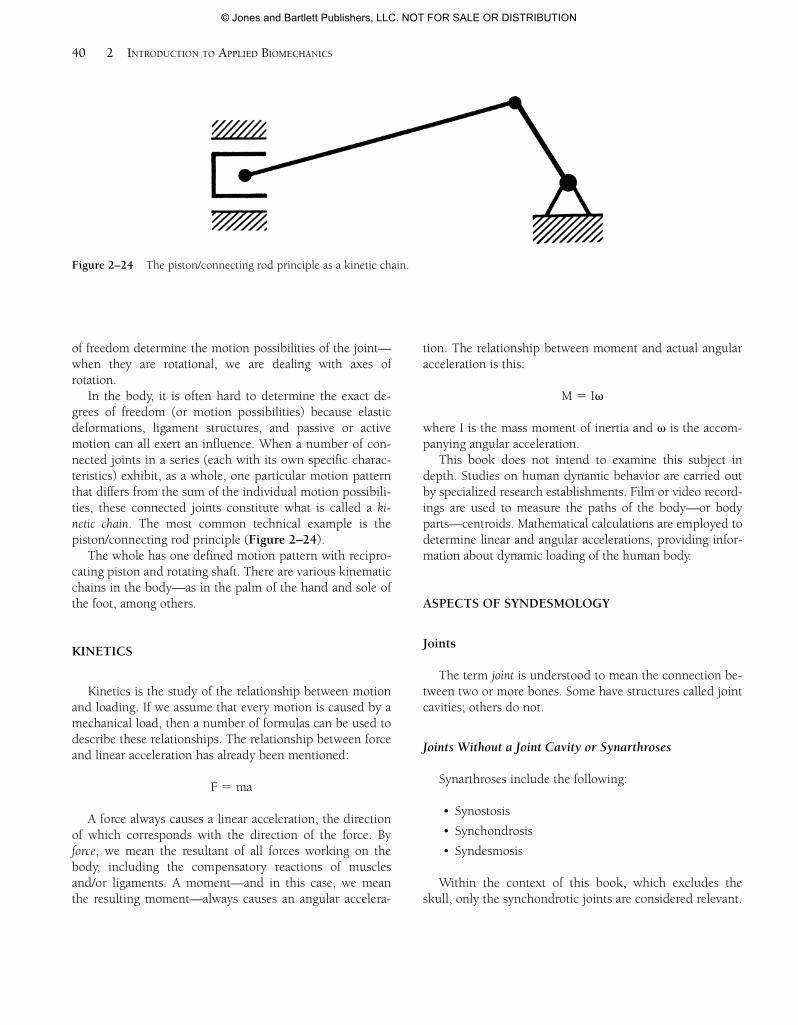
In the body, it is often hard to determine the exact de-grees of freedom (or motion possibilities) because elasticdeformations, ligament structures, and passive or activemotion can all exert an influence. When a number of con-nected joints in a series (each with its own specific charac-teristics) exhibit, as a whole, one particular motion patternthat differs from the sum of the individual motion possibili-ties, these connected joints constitute what is called a ki-netic chain. The most common technical example is thepiston/connecting rod principle (Figure 2–24).
The whole has one defined motion pattern with recipro-cating piston and rotating shaft. There are various kinematicchains in the body—as in the palm of the hand and sole ofthe foot, among others.
KINETICS
Kinetics is the study of the relationship between motionand loading. If we assume that every motion is caused by amechanical load, then a number of formulas can be used todescribe these relationships. The relationship between forceand linear acceleration has already been mentioned:
F 5 ma
A force always causes a linear acceleration, the directionof which corresponds with the direction of the force. Byforce, we mean the resultant of all forces working on thebody, including the compensatory reactions of musclesand/or ligaments. A moment—and in this case, we meanthe resulting moment—always causes an angular accelera-
tion. The relationship between moment and actual angularacceleration is this:
M 5 Iv
where I is the mass moment of inertia and v is the accom-panying angular acceleration.
This book does not intend to examine this subject indepth. Studies on human dynamic behavior are carried outby specialized research establishments. Film or video record-ings are used to measure the paths of the body—or bodyparts—centroids. Mathematical calculations are employed todetermine linear and angular accelerations, providing infor-mation about dynamic loading of the human body.
ASPECTS OF SYNDESMOLOGY
Joints
The term joint is understood to mean the connection be-tween two or more bones. Some have structures called jointcavities; others do not.
Joints Without a Joint Cavity or Synarthroses
Synarthroses include the following:
• Synostosis
• Synchondrosis
• Syndesmosis
Within the context of this book, which excludes theskull, only the synchondrotic joints are considered relevant.
40 2 INTRODUCTION TO APPLIED BIOMECHANICS
Figure 2–24 The piston/connecting rod principle as a kinetic chain.
55942_CH02_Vander.qxd 2/7/09 9:37 AM Page 40
© Jones and Bartlett Publishers, LLC. NOT FOR SALE OR DISTRIBUTION
Joints With a Joint Cavity or Diarthroses
A diarthrosis or synovial joint possesses a number ofobligatory and some optional features. The obligatory fea-tures are these:
• Bone ends: two (simple joint) or more (compositejoint)
• Joint cartilage
• Joint lubrication
• Joint cavity
• Capsule: synovial and fibrous membrane
The optional features are as follows:
• Cartilage structures (meniscus, disk)
• Capsular reinforcement fibers or capsular ligaments
• Capsular folds
• Meniscoid folds
Morphology
The morphology of a distal end of a bone that makes upa joint can be one of the following:
• Biconcave
• Biconvex
• Concave-convex
The condyloid joint (biconvex or biconcave) and thesaddle joint (concave-convex) represent, therefore, the twobasic morphologies of joints. Flat joints are theoreticallypossible, and the ball-and-socket joint is a derivative of thecondyloid joint. The cylindrical joint is structurally some-what similar to the saddle joint. Cylindrical joints come intwo types: hinge joints and pivot joints. In these joints,movement can occur around or along imaginary axes. Thedegrees of freedom available for movement can be con-verted into a number of axes of rotation. We can distinguishthe following:
• Two axes for the condyloid joints
• Two axes for the saddle joints
• Two axes for the cylindrical joints
• Three axes for ball-and-socket joints
As a rule, the cylindrical joint does not utilize one of its degrees of freedom. This is a result of limitations im-
posed by bony, structural, physiologic, and/or ligamentous restrictions.
Whether highly complex or relatively simple, the articu-lations between two vertebrae (odontoid, intervertebraldisk, intervertebral joints, and uncovertebral joints) fromthe atlanto-occipital joints down to and including thesacroiliac joints have three degrees of freedom. Movementalong any of these degrees of freedom is limited by bone orligament.
Literature dealing with movement mentions three sepa-rate planes and an average range of motion expressed in an-gular degrees. However, as with all physiologic movements,no motion is a pure uniplanar movement. This point isclearly demonstrated by the relationship between the inter-vertebral joints in the cervical spine and their inability tomove in a purely transverse plane and a purely frontalplane.
Basic Movement Types
Theoretically, there are two basic movement types: rota-tional and translational. For explanatory text and drawings,see Chapter 2 on “Kinematics” on pages 37–38.
To a significant extent, every component in the jointmechanism plays a role in determining the following:
• The shape of the peripheral movement trajectory
• The intra-articular movement behavior
Peripheral Movement Trajectory
A peripheral movement trajectory can be broken downinto a swing and a rotational movement (spin or conjunctrotation).
Swing. A movement is described as a swing when a changeoccurs in the angular relationship between the longitudi-nal axes of the bones belonging to the joint in question.If a swing movement occurs around one axis, it is calleda pure swing or a cardinal swing (Figure 2–25). If, dur-ing a swing movement, a secondary movement occursaround another axis, it is called an impure swing or ar-cuate swing. This arcuate swing is significant in achiev-ing the close-packed position.
Spin. By spin, we mean the movement of a bone around afixed mechanical axis that coincides in its location withthe normal (N in Figure 2–26) in the point of contactbetween the two joint surfaces. A single point on one ofthe joint surfaces remains in contact with a single point
Aspects of Syndesmology 41
55942_CH02_Vander.qxd 2/7/09 9:37 AM Page 41
© Jones and Bartlett Publishers, LLC. NOT FOR SALE OR DISTRIBUTION
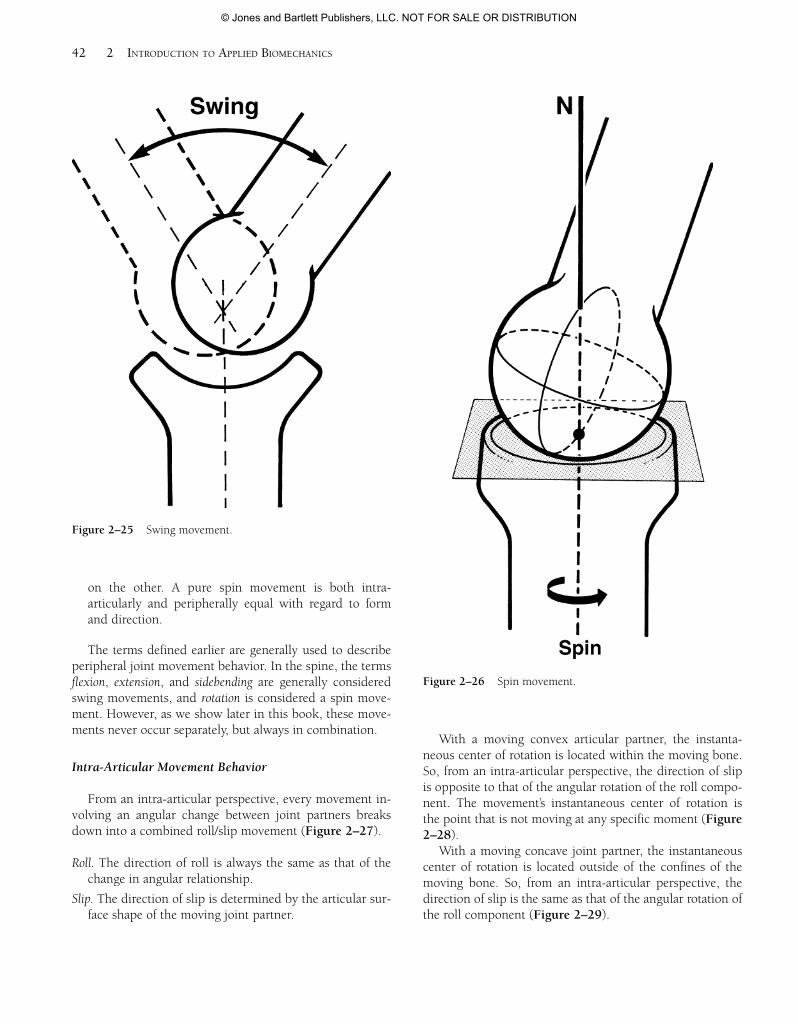
on the other. A pure spin movement is both intra-articularly and peripherally equal with regard to formand direction.
The terms defined earlier are generally used to describeperipheral joint movement behavior. In the spine, the termsflexion, extension, and sidebending are generally consideredswing movements, and rotation is considered a spin move-ment. However, as we show later in this book, these move-ments never occur separately, but always in combination.
Intra-Articular Movement Behavior
From an intra-articular perspective, every movement in-volving an angular change between joint partners breaksdown into a combined roll/slip movement (Figure 2–27).
Roll. The direction of roll is always the same as that of thechange in angular relationship.
Slip. The direction of slip is determined by the articular sur-face shape of the moving joint partner.
With a moving convex articular partner, the instanta-neous center of rotation is located within the moving bone.So, from an intra-articular perspective, the direction of slipis opposite to that of the angular rotation of the roll compo-nent. The movement’s instantaneous center of rotation isthe point that is not moving at any specific moment (Figure2–28).
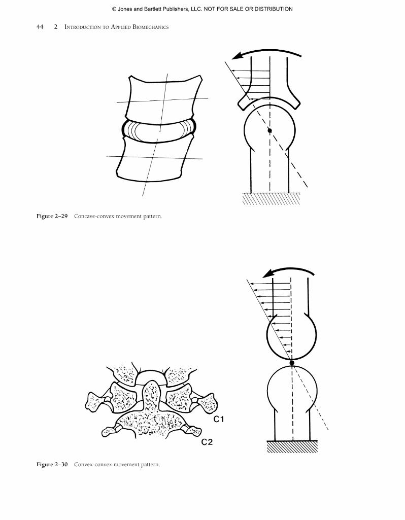
With a moving concave joint partner, the instantaneouscenter of rotation is located outside of the confines of themoving bone. So, from an intra-articular perspective, thedirection of slip is the same as that of the angular rotation ofthe roll component (Figure 2–29).
42 2 INTRODUCTION TO APPLIED BIOMECHANICS
Figure 2–25 Swing movement.
Figure 2–26 Spin movement.
55942_CH02_Vander.qxd 2/7/09 9:37 AM Page 42
© Jones and Bartlett Publishers, LLC. NOT FOR SALE OR DISTRIBUTION
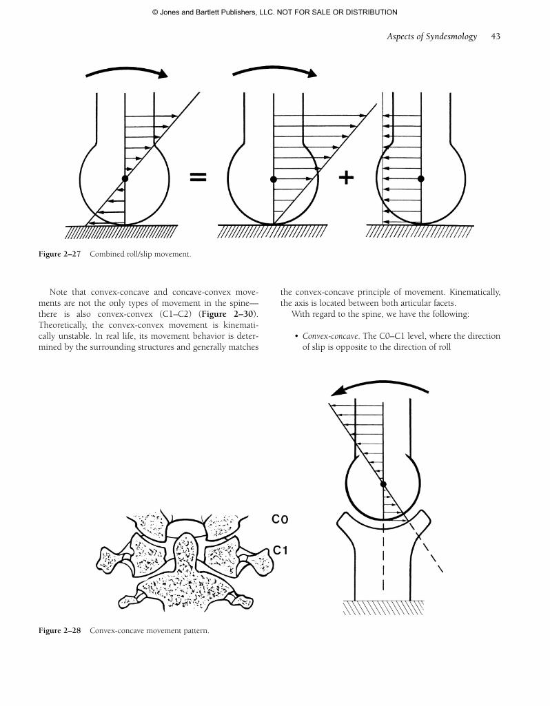
Note that convex-concave and concave-convex move-ments are not the only types of movement in the spine—there is also convex-convex (C1–C2) (Figure 2–30).Theoretically, the convex-convex movement is kinemati-cally unstable. In real life, its movement behavior is deter-mined by the surrounding structures and generally matches
the convex-concave principle of movement. Kinematically,the axis is located between both articular facets.
With regard to the spine, we have the following:
• Convex-concave. The C0–C1 level, where the directionof slip is opposite to the direction of roll
Aspects of Syndesmology 43
Figure 2–27 Combined roll/slip movement.
Figure 2–28 Convex-concave movement pattern.
55942_CH02_Vander.qxd 2/7/09 9:37 AM Page 43
© Jones and Bartlett Publishers, LLC. NOT FOR SALE OR DISTRIBUTION
44 2 INTRODUCTION TO APPLIED BIOMECHANICS
Figure 2–29 Concave-convex movement pattern.
Figure 2–30 Convex-convex movement pattern.
55942_CH02_Vander.qxd 2/7/09 9:37 AM Page 44
© Jones and Bartlett Publishers, LLC. NOT FOR SALE OR DISTRIBUTION
• Convex-convex. The C1–C2 level, where the directionof slip is opposite to the direction of roll
• Concave-convex. The levels below C2, where the di-rection of slip is the same as the direction of roll
The slip component increases in line with the distancebetween the instantaneous center of rotation and the actualjoint surface (see the section titled “Examination of theLower and Mid-Cervical Spine” in Chapter 16). Where thearticular facets of the intervertebral joints have a limited ra-dius of curvature, there is a relatively large translationalcomponent. Therapeutically, in mobilization of the C0–C1joint and with traction mobilization in general, the move-ment focus is mostly on the translational component.
Joint Positions
In examination and therapy, knowledge of the joint posi-tions is important. The following joint positions can beidentified:
• Maximally close-packed position
• Close-packed position
• Maximally loose-packed position
• Loose-packed position
Maximally Close-Packed Position
The maximally close-packed position is a three-dimensional endrange position of the joint, where there isbone restriction and/or maximal capsular or ligamentoustension. This is caused by conjunct rotation.
The implication of the maximally close-packed positionis threefold:
• Mobilization is physiologically impossible.
• There is optimal stability.
• It can be used as a locking technique to create a leverfunction during mobilization and manipulation techniques.
Close-Packed Position
The close-packed position is all one- or two-dimensionalendrange positions of the joint where bony restriction oc-curs and/or a part of the capsule and certain ligaments aremaximally tensed. In both cases, the capsular and ligamen-tous tension and gravity cause a compression of the joint
surfaces relative to each other. During active motion, themuscle tone also plays a role.
Maximally Loose-Packed Position
The maximally loose-packed position here means the cap-sule and the ligamentous and muscular complex are maxi-mally relaxed. The joint is in the so-called physiologic orpathologic resting position.
The importance of the maximally loose-packed positionis threefold:
• Unloading of joint, capsule, and ligaments
• Examination of the movement possibilities in thephysiologic directions starting from this position
• Traction examination from this position
Loose-Packed Position
The loose-packed position is a position between close-packed and maximally loose-packed.
Interpretation of the aforementioned terminology withregard to the spine
Maximally close-packed position
Extension, sidebending, and contralateral or ipsiexternalrotation. Flexion, sidebending, and contralateral or ipsiex-ternal rotation.
Close-packed position
All other endrange positions.
Maximally loose-packed position
Midposition between flexion and extension, left andright sidebending and left and right rotation.
Loose-packed position
All positions where the total capsule and ligamentouscomplex is neither maximally tensed nor maximally re-laxed. In these positions, some capsule structures and liga-ments will exhibit more tension than others.
Aspects of Syndesmology 45
55942_CH02_Vander.qxd 2/7/09 9:37 AM Page 45
© Jones and Bartlett Publishers, LLC. NOT FOR SALE OR DISTRIBUTION

55942_CH02_Vander.qxd 2/7/09 9:37 AM Page 46
© Jones and Bartlett Publishers, LLC. NOT FOR SALE OR DISTRIBUTION