Embed Size (px)
Citation preview

Introduction to
GPR Ground Penetrating Radar
PHYTOSEQUESTRATION WORKSHOP
JULY 23RD & 24TH, 2015
CHICAGO,ILLINIOS
ORGAINZED BY
PRESENTED BY SCOTT MACINTOSH
www.blackcatscience.com
1

Purpose of Presentation
Introduce those unfamiliar with GPR to its basic functionality and
how it could be used for Phytosequestration
What is GPR, What does it measure and Why use it.
Overview of a GPR System
Operating Frequency, Spatial Resolution, Penetration Depth
Effects of Soil, Clutter
Example Data / Simulation 2-3 slides
Imaging vs. Non-Imaging
2

What is GPR
• A method for non-invasively
probing below ground surface
using back-scattered
electromagnetic radiation.
• Measures variations in the
electromagnetic properties of
materials.
• Changes in dielectric and conductivity properties.
• Rapidly measure large areas.
• Provides detailed localized data (3D-images) of subsurface
features.
3

Conclusions
GPR can be used to produce 3D images of root structures
GPR can be used to monitor and estimate root growth/biomass
Direct measurements & change detection
cm to cub-cm voxel resolution may be possible under right soil conditions.
Soil characteristics will determine overall performance/limitation of GPR
Upper operating frequency <10GHz (needs further investigation)
Penetration depth in good soils @ 10GHz ~0.5m (needs further investigation)Hetero
Non-Homogenous conductive soils are bad for GPR performance
Uniform non-conductive soils are good for GPR performance
4

GPR System
Typical Center Frequencies
100 MHz – 2GHz
Typical Bandwidth
100MHz – 1GHz
Typical Penetration Depth
Good Soil Bad Soil
(Dry Sand) (Wet Clay)
1-10m 0.01 – 2 m
TransmitterAntenna
Receiver
Antenna
Scattering Object
Sub-surface
Air
Ground Layer
Filter A2D
LNAPA
Source• Pulse• FMCW
𝑐𝑎𝑖𝑟 ≈ 3𝑒8 𝑚/𝑠
𝑐𝑠𝑠 =𝑐
휀𝑟_𝑠𝑠
𝑐𝑠𝑜 =𝑐
휀𝑟_𝑠𝑜clutter
5

General Factors That Effect GPR
Performance
Frequency
Wavelength
Penetration
Lateral resolution
6
Higher frequency = shorter wavelength
Shorter wave length = better cross range resolution
Higher frequency = decreases penetration
Increased Bandwidth = better depth resolution

Resolution
Lateral Resolution Depth Resolution
∆𝑥 =𝜆𝑟𝐷𝑅 ∆𝑥𝑠𝑎𝑟=
𝜆𝑟2𝐷𝑠𝑎𝑟
𝑅
𝜆𝑟 =𝑐𝑟𝑓
𝑐𝑟 =𝑐
휀𝑟
휀𝑟 = 1 𝑎𝑖𝑟휀𝑟 = 3 − 10 (𝑠𝑜𝑖𝑙𝑠)
∆𝑧 =𝑐𝑟
2 × 𝐵𝑎𝑛𝑑𝑤𝑖𝑑𝑡ℎ
D = 0.75m
7

Attenuation
http://www.3d-radar.com/wp-content/uploads/2014/02/SNR-in-3dr-GPR.pdf
Ground Penetrating Radar, 2nd Edition. David J. Daniels
𝐿𝑎 = 2 × 𝑅 × 2𝜋𝑓𝜇0𝜇𝑟휀0휀𝑟
21 + 𝑡𝑎𝑛2𝛿 − 1
𝑡𝑎𝑛𝛿 =𝜎𝑑𝑐
𝜔휀0휀𝑟+
휀′′
휀0휀𝑟
8
Conductive soils, such as wet
clays quickly attenuate radar
signals and significantly limit
the penetration depth

iGPR
imaging Ground Penetrating Radar
9
iGPR = Data Collection Method + Processing
INSERT 3D IMAGE HERE
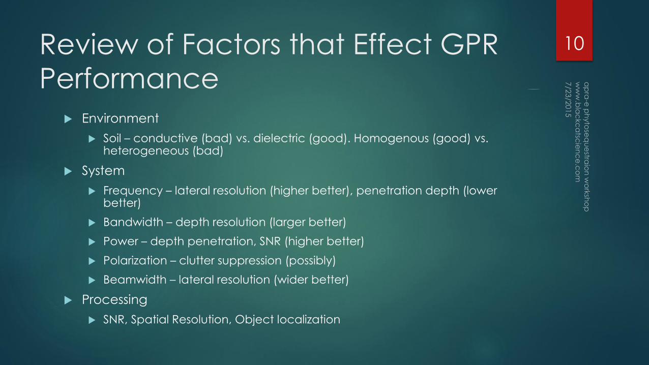
Review of Factors that Effect GPR
Performance
Environment
Soil – conductive (bad) vs. dielectric (good). Homogenous (good) vs. heterogeneous (bad)
System
Frequency – lateral resolution (higher better), penetration depth (lower better)
Bandwidth – depth resolution (larger better)
Power – depth penetration, SNR (higher better)
Polarization – clutter suppression (possibly)
Beamwidth – lateral resolution (wider better)
Processing
SNR, Spatial Resolution, Object localization
10

Example 3D GPR Data
Visible GPR Depth Slice
11

Resources
Literature
Ground Penetrating Radar, 2nd Edition. David J. Daniels
GPR Soil Suitability Maps of US
http://www.nrcs.usda.gov/wps/portal/nrcs/detail/soils/use/maps/?cid=nrcs142p2_053622
GPR Equipment Manufacturers
IDS
3D-Radar
Mala-Geosciences
GSSI
Professional Societies
Near Surface Geophysics - European Association of Geophysicists & Engineers www.nsg-eage.org
Environmental and Engineering Geophysical Society www.eegs.org
Society for Exploration Geophysics www.seg.org
12