Embed Size (px)
Citation preview
8/11/2019 Introduction to Helicopters Aerodynamics
http://slidepdf.com/reader/full/introduction-to-helicopters-aerodynamics 1/102
INTRODUCTION
The wings of the airplane create a lift force
when they move through the air. As we known,
during ight, there are four forces acting on the
helicopter and those are LIFT , DA! ,
T"#$T ,and %&I!"T. In order to make thewings to move through the air , of course, the
helicopter itself has to move. A helicopter works
'y having its wings move through the air while
the 'ody stays still. The helicopter(s wings are
called )ain otor *lades. The shape and the
angle of the 'lades move through the air will
determine how much Lift force is created. After
the helicopter lifted o+ the ground, the pilot can
8/11/2019 Introduction to Helicopters Aerodynamics
http://slidepdf.com/reader/full/introduction-to-helicopters-aerodynamics 2/102
tilt the 'lades, causing the helicopter to tip
forward or 'ackward or sideward.
HISTORICAL
BACKGROUND
The helicopter is argua'ly one of the earliest
ideas for achieving ight. ver two thousand
years ago, the -hinese constructed what are
8/11/2019 Introduction to Helicopters Aerodynamics
http://slidepdf.com/reader/full/introduction-to-helicopters-aerodynamics 3/102
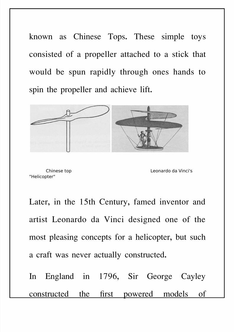
known as -hinese Tops. These simple toys
consisted of a propeller attached to a stick thatwould 'e spun rapidly through ones hands to
spin the propeller and achieve lift.
Chinese top Leonardo da Vinci's
"Helicopter"
Later, in the /th -entury, famed inventor and
artist Leonardo da 0inci designed one of the
most pleasing concepts for a helicopter, 'ut such
a craft was never actually constructed.
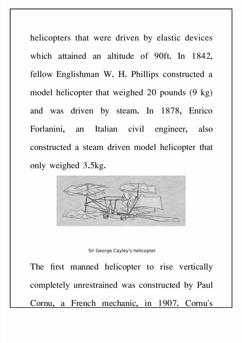
In &ngland in 123, $ir !eorge -ayley
constructed the 4rst powered models of
8/11/2019 Introduction to Helicopters Aerodynamics
http://slidepdf.com/reader/full/introduction-to-helicopters-aerodynamics 4/102
helicopters that were driven 'y elastic devices
which attained an altitude of 25ft. In 678,fellow &nglishman %. ". 9hillips constructed a
model helicopter that weighed 85 pounds :2 kg;
and was driven 'y steam. In 616, &nrico
Forlanini, an Italian civil engineer, also
constructed a steam driven model helicopter that
only weighed <./kg.
Sir George Cayley's helicopter
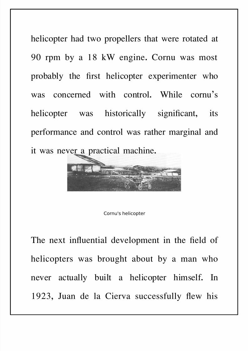
The 4rst manned helicopter to rise vertically
completely unrestrained was constructed 'y 9aul
-ornu, a French mechanic, in 251. -ornu(s
8/11/2019 Introduction to Helicopters Aerodynamics
http://slidepdf.com/reader/full/introduction-to-helicopters-aerodynamics 5/102
helicopter had two propellers that were rotated at
25 rpm 'y a 6 k% engine. -ornu was mostpro'a'ly the 4rst helicopter e=perimenter who
was concerned with control. %hile cornu>s
helicopter was historically signi4cant, its
performance and control was rather marginal and
it was never a practical machine.
Cornu's helicopter
The ne=t inuential development in the 4eld of
helicopters was 'rought a'out 'y a man who
never actually 'uilt a helicopter himself. In
28<, ?uan de la -ierva successfully ew his
8/11/2019 Introduction to Helicopters Aerodynamics
http://slidepdf.com/reader/full/introduction-to-helicopters-aerodynamics 6/102
-.7 autogiro, an aircraft that has two propellers,
a powered one to provide thrust, and an unpowered rotor to provide lift. -ierva(s autogiro
was noteworthy 'ecause it was the 4rst to use
an @articulated@ rotor that allowed its 'lades to
ap up and down in response to aerodynamic
forces on the 'lades during forward ight.The
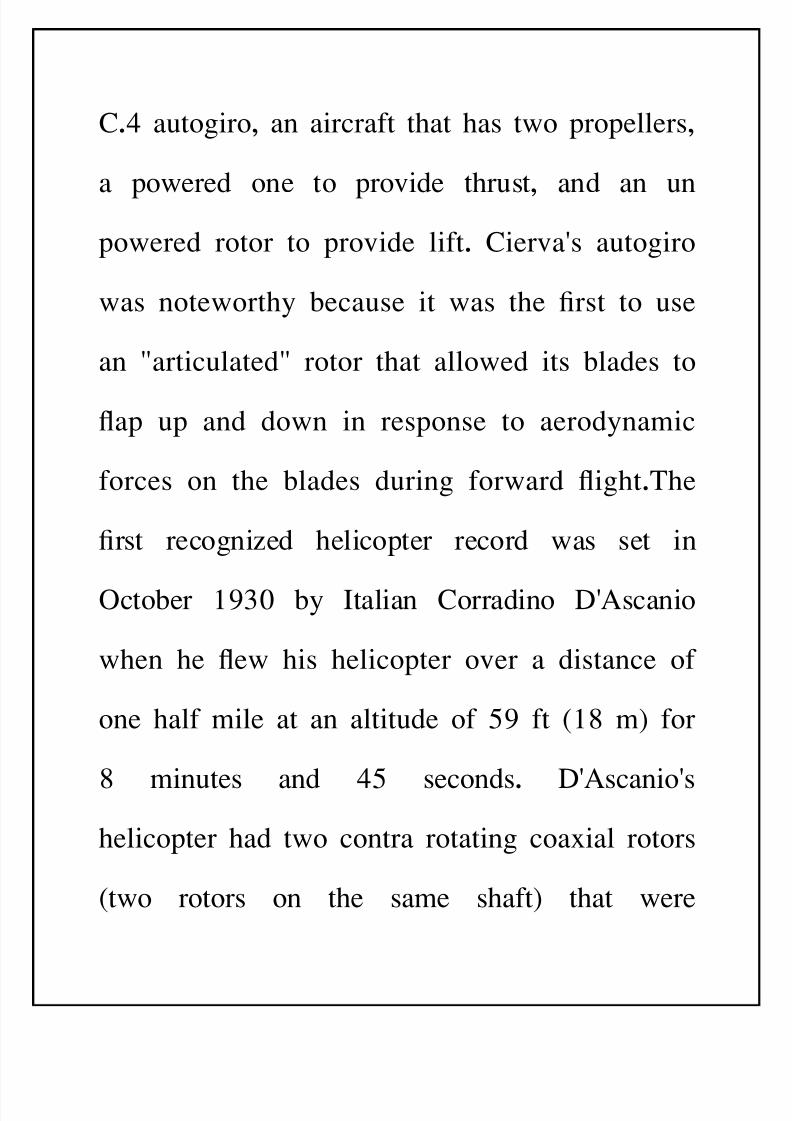
4rst recognied helicopter record was set in
cto'er 2<5 'y Italian -orradino D(Ascanio
when he ew his helicopter over a distance of
one half mile at an altitude of /2 ft :6 m; for
6 minutes and 7/ seconds. D(Ascanio(s
helicopter had two contra rotating coa=ial rotors
:two rotors on the same shaft; that were
8/11/2019 Introduction to Helicopters Aerodynamics
http://slidepdf.com/reader/full/introduction-to-helicopters-aerodynamics 7/102
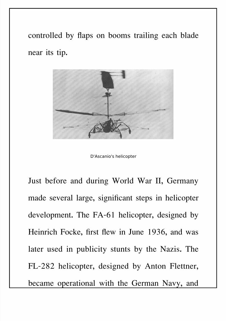
controlled 'y aps on 'ooms trailing each 'lade
near its tip.
D'Ascanio's helicopter
?ust 'efore and during %orld %ar II, !ermany
made several large, signi4cant steps in helicopter
development. The FAB3 helicopter, designed 'y
"einrich Focke, 4rst ew in ?une 2<3, and was
later used in pu'licity stunts 'y the Cais. The
FLB868 helicopter, designed 'y Anton Flettner,
'ecame operational with the !erman Cavy, and
8/11/2019 Introduction to Helicopters Aerodynamics
http://slidepdf.com/reader/full/introduction-to-helicopters-aerodynamics 8/102
over 555 of them were produced. This
helicopter utilied twinBintermeshing rotors, hada forward speed of 7/ kmh, and could operate
at an altitude of <,23/ m with a payload of <35
kg.
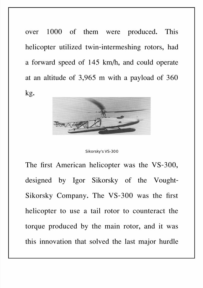
Sikorsky's VS-300
The 4rst American helicopter was the 0$B<55,
designed 'y Igor $ikorsky of the 0oughtB
$ikorsky -ompany. The 0$B<55 was the 4rst
helicopter to use a tail rotor to counteract the
torEue produced 'y the main rotor, and it was
this innovation that solved the last maor hurdle
8/11/2019 Introduction to Helicopters Aerodynamics
http://slidepdf.com/reader/full/introduction-to-helicopters-aerodynamics 9/102
in making helicopters practical ying vehicles.
This design is now the most common in today(shelicopters.
NOMENCLATURE AND
TECHNICAL TERM
Bernoulli's principle: This principle states that as the air
velocity increases, the pressure decreasesG and as the
velocity decreases, the pressure increases.
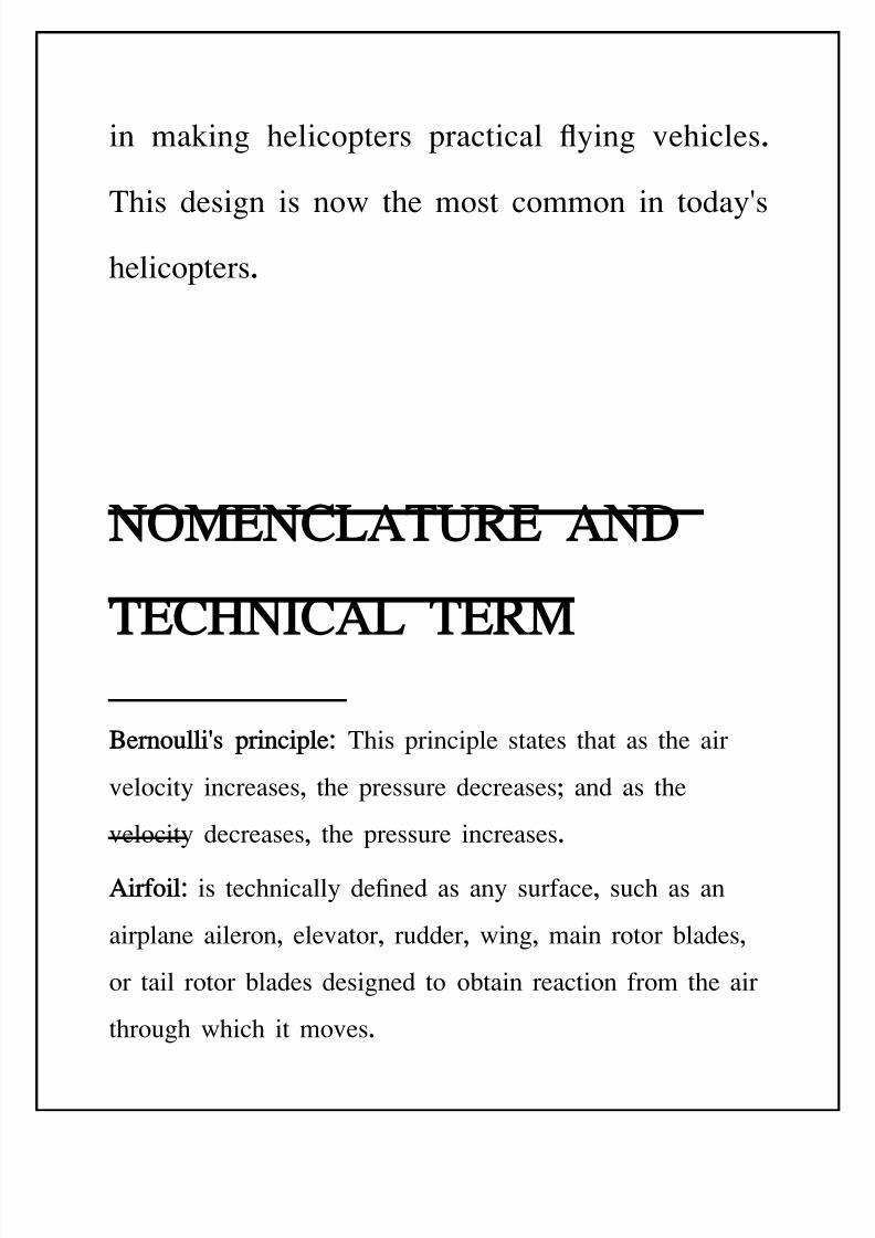
Airfoil: is technically de4ned as any surface, such as an
airplane aileron, elevator, rudder, wing, main rotor 'lades,
or tail rotor 'lades designed to o'tain reaction from the air
through which it moves.
8/11/2019 Introduction to Helicopters Aerodynamics
http://slidepdf.com/reader/full/introduction-to-helicopters-aerodynamics 10/102
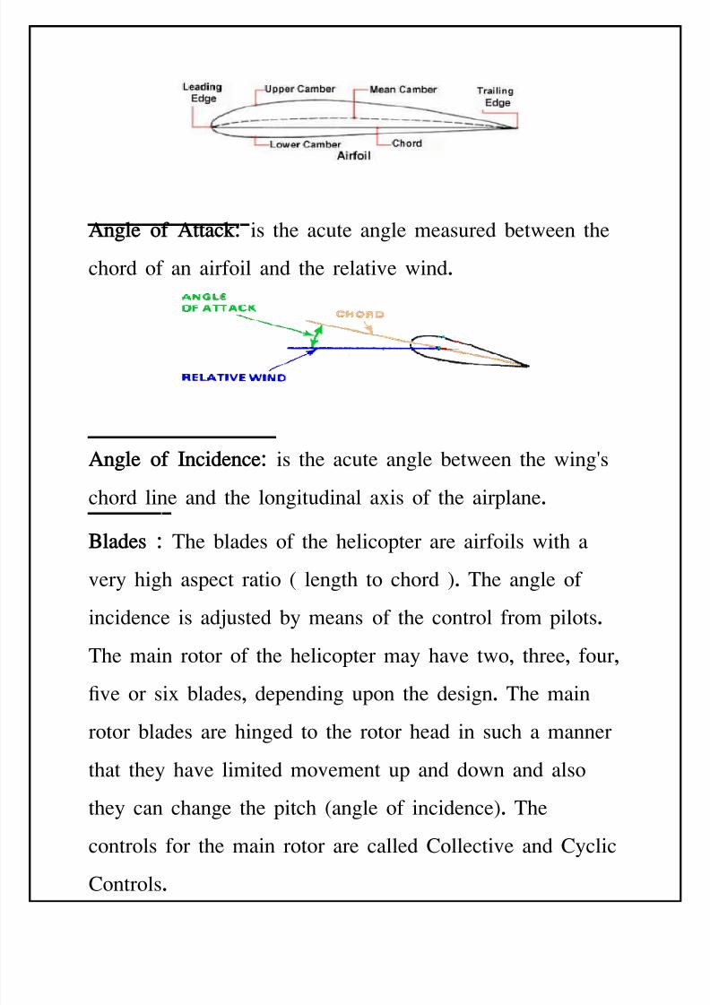
Anle of A!!"c#: is the acute angle measured 'etween the
chord of an airfoil and the relative wind.
Anle of Inci$ence: is the acute angle 'etween the wing(s
chord line and the longitudinal a=is of the airplane.
Bl"$es : The 'lades of the helicopter are airfoils with a
very high aspect ratio : length to chord ;. The angle of
incidence is adusted 'y means of the control from pilots.
The main rotor of the helicopter may have two, three, four,
4ve or si= 'lades, depending upon the design. The mainrotor 'lades are hinged to the rotor head in such a manner
that they have limited movement up and down and also
they can change the pitch :angle of incidence;. The
controls for the main rotor are called -ollective and -yclic
-ontrols.
8/11/2019 Introduction to Helicopters Aerodynamics
http://slidepdf.com/reader/full/introduction-to-helicopters-aerodynamics 11/102
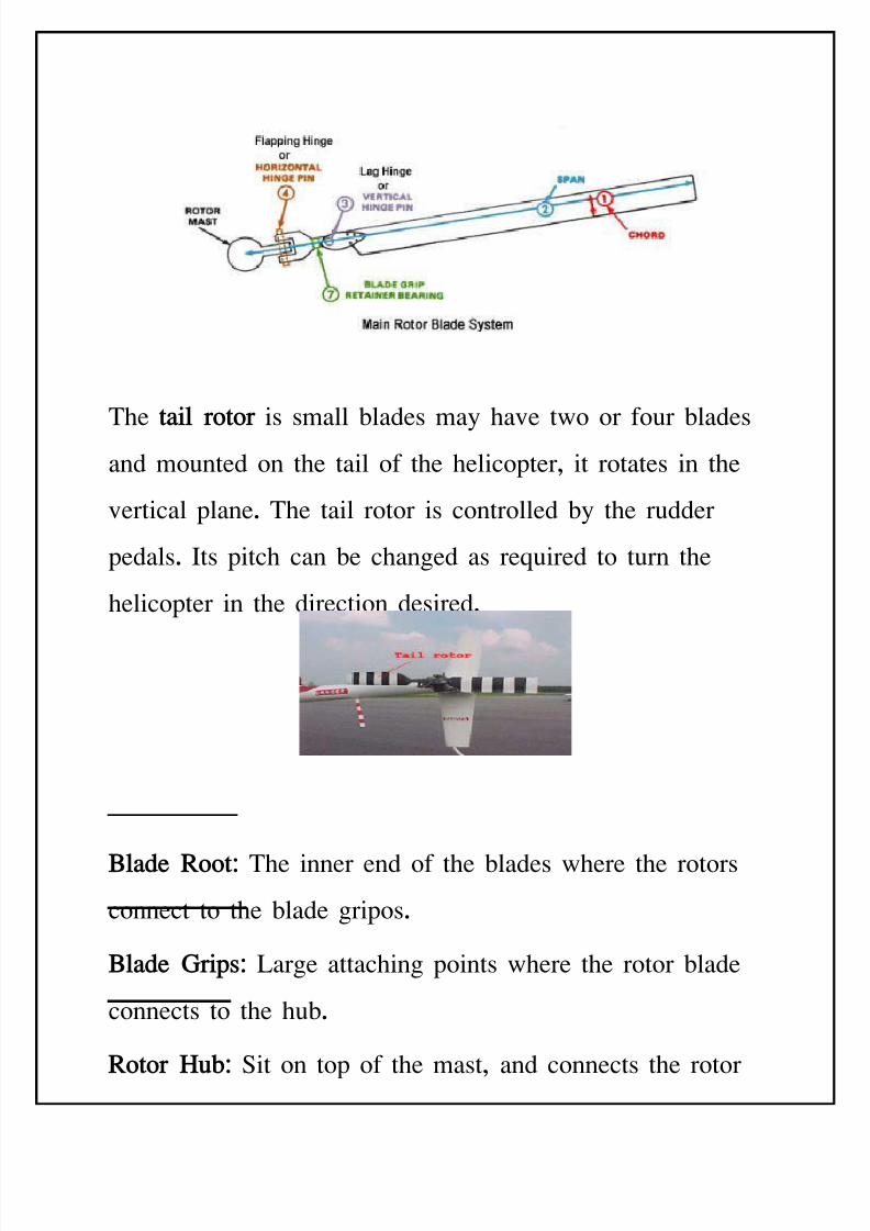
The !"il ro!or is small 'lades may have two or four 'lades
and mounted on the tail of the helicopter, it rotates in the
vertical plane. The tail rotor is controlled 'y the rudder
pedals. Its pitch can 'e changed as reEuired to turn the
helicopter in the direction desired.
Bl"$e Roo!: The inner end of the 'lades where the rotors
connect to the 'lade gripos.
Bl"$e Grips: Large attaching points where the rotor 'lade
connects to the hu'.
Ro!or Hu%: $it on top of the mast, and connects the rotor
8/11/2019 Introduction to Helicopters Aerodynamics
http://slidepdf.com/reader/full/introduction-to-helicopters-aerodynamics 12/102
'lades to the control tu'es.
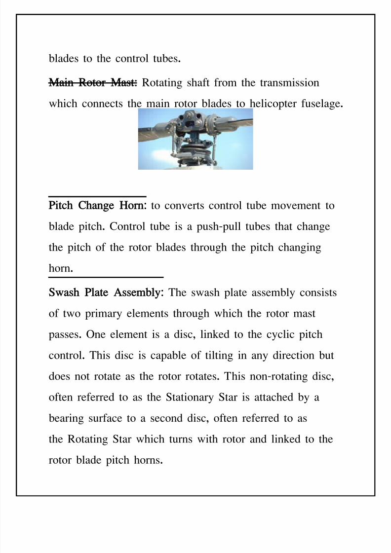
M"in Ro!or M"s!: otating shaft from the transmission
which connects the main rotor 'lades to helicopter fuselage.
&i!c C"ne Horn: to converts control tu'e movement to
'lade pitch. -ontrol tu'e is a pushBpull tu'es that change
the pitch of the rotor 'lades through the pitch changing
horn.
S("s &l"!e Asse)%l*: The swash plate assem'ly consists
of two primary elements through which the rotor mast
passes. ne element is a disc, linked to the cyclic pitch
control. This disc is capa'le of tilting in any direction 'ut
does not rotate as the rotor rotates. This nonBrotating disc,
often referred to as the $tationary $tar is attached 'y a
'earing surface to a second disc, often referred to as
the otating $tar which turns with rotor and linked to the
rotor 'lade pitch horns.
8/11/2019 Introduction to Helicopters Aerodynamics
http://slidepdf.com/reader/full/introduction-to-helicopters-aerodynamics 13/102
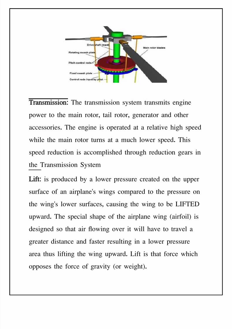
Tr"ns)ission: The transmission system transmits engine
power to the main rotor, tail rotor, generator and other
accessories. The engine is operated at a relative high speed
while the main rotor turns at a much lower speed. This
speed reduction is accomplished through reduction gears in
the Transmission $ystem
Lif!: is produced 'y a lower pressure created on the upper
surface of an airplane(s wings compared to the pressure on
the wing(s lower surfaces, causing the wing to 'e LIFT&D
upward. The special shape of the airplane wing :airfoil; is
designed so that air owing over it will have to travel agreater distance and faster resulting in a lower pressure
area thus lifting the wing upward. Lift is that force which
opposes the force of gravity :or weight;.
8/11/2019 Introduction to Helicopters Aerodynamics
http://slidepdf.com/reader/full/introduction-to-helicopters-aerodynamics 14/102
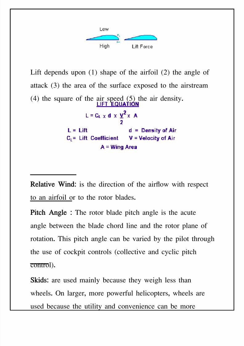
Lift depends upon :; shape of the airfoil :8; the angle of
attack :<; the area of the surface e=posed to the airstream
:7; the sEuare of the air speed :/; the air density.
Rel"!i+e ,in$: is the direction of the airow with respect
to an airfoil or to the rotor 'lades.
&i!c Anle : The rotor 'lade pitch angle is the acute
angle 'etween the 'lade chord line and the rotor plane of
rotation. This pitch angle can 'e varied 'y the pilot throughthe use of cockpit controls :collective and cyclic pitch
control;.
S#i$s: are used mainly 'ecause they weigh less than
wheels. n larger, more powerful helicopters, wheels are
used 'ecause the utility and convenience can 'e more
8/11/2019 Introduction to Helicopters Aerodynamics
http://slidepdf.com/reader/full/introduction-to-helicopters-aerodynamics 15/102
important than the savings in weight. In order to move a
skidBeEuipped helicopter on the ground, one has to attach a
set of groundBhandling wheels, ack up the helicopter, and
roll it :into the hangar for maintenance;. If your helicopter
already has the wheels as a permanent feature, it is more
convenient to move around when the engine is shut down
or the pilot has wandered o+.
GENERAL Lift is o'tained 'y means of one or more power driven
horiontal propellers which called )ain otor. %hen the
main rotor of helicopter turns it produces lift and reaction
torEue. eaction torEue tends to make helicopter spin. n
most helicopters, a small rotor nears the tail which
called tail rotorcompensates for this torEue. n twin rotor
8/11/2019 Introduction to Helicopters Aerodynamics
http://slidepdf.com/reader/full/introduction-to-helicopters-aerodynamics 16/102
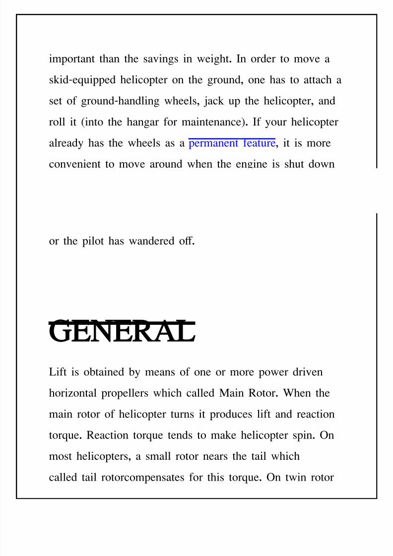
helicopter the rotors rotate in opposite directions, their
reactions cancel each other.
M"in Ro!or:
The lifting force is produced 'y the main rotor . As they
spin in the air and produced the lift. &ach 'lade produces
an eEual share of the lifting force. The weight of a
helicopter is divided evenly 'etween the rotor 'lades on themain rotor system. If a helicopter weight 7555 l's and it
has two 'lades, then each 'lade must 'e a'le to support
8555 l's. In addition to the static weight of helicopter
,each 'lade must 'e accept dynamic load as well .
T"il Ro!or:
The tail rotor is very important. If you spin a rotor with an
engine, the rotor will rotate, 'ut the engine and helicopter
'ody will tend to rotate in opposite direction to the rotor.
This is called TorEue reaction. Cewton(s third law of
8/11/2019 Introduction to Helicopters Aerodynamics
http://slidepdf.com/reader/full/introduction-to-helicopters-aerodynamics 17/102
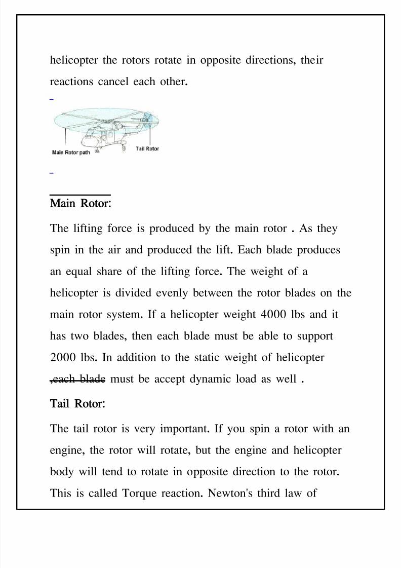
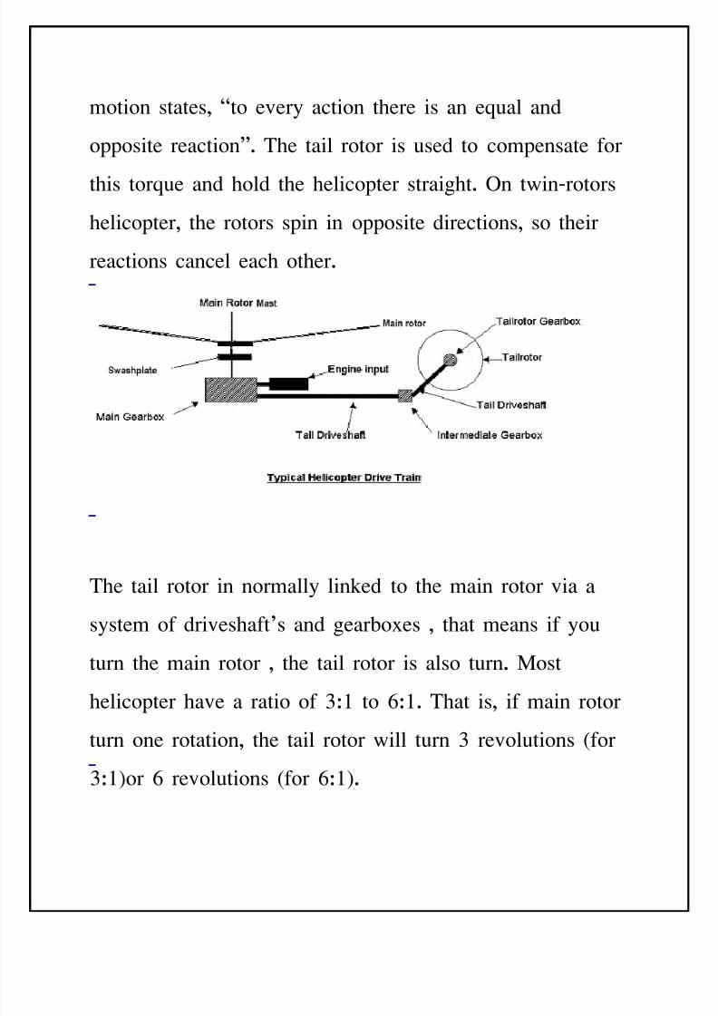
motion states, Hto every action there is an eEual and
opposite reaction. The tail rotor is used to compensate for
this torEue and hold the helicopter straight. n twinBrotors
helicopter, the rotors spin in opposite directions, so their
reactions cancel each other.
The tail rotor in normally linked to the main rotor via a
system of driveshaft>s and gear'o=es , that means if you
turn the main rotor , the tail rotor is also turn. )ost
helicopter have a ratio of <J to 3J. That is, if main rotorturn one rotation, the tail rotor will turn < revolutions :for
<J;or 3 revolutions :for 3J;.
8/11/2019 Introduction to Helicopters Aerodynamics
http://slidepdf.com/reader/full/introduction-to-helicopters-aerodynamics 18/102
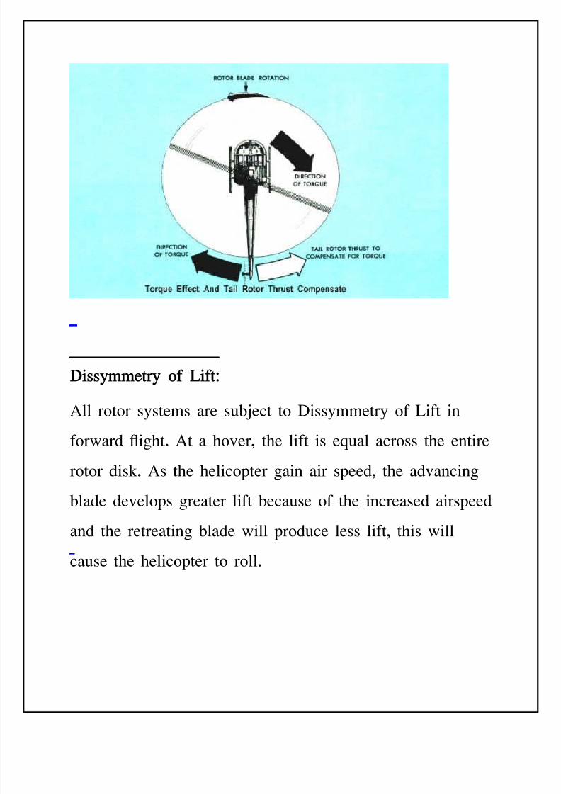
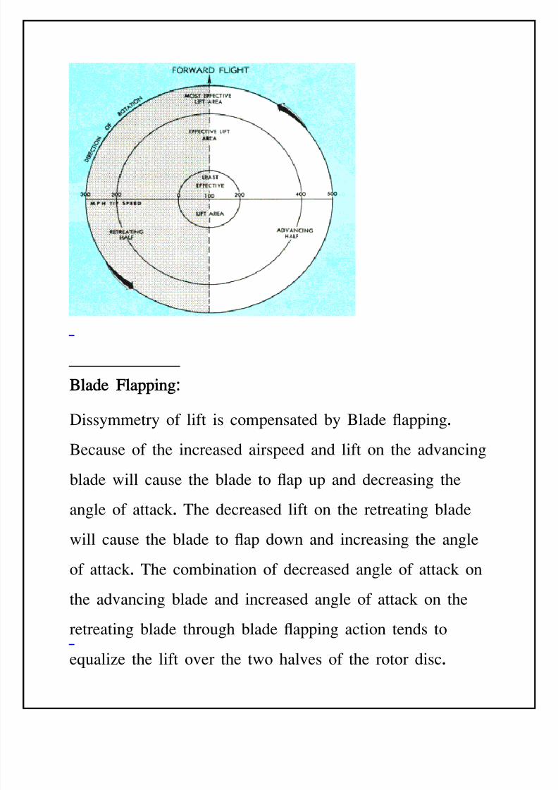
Diss*))e!r* of Lif!:
All rotor systems are su'ect to Dissymmetry of Lift inforward ight. At a hover, the lift is eEual across the entire
rotor disk. As the helicopter gain air speed, the advancing
'lade develops greater lift 'ecause of the increased airspeed
and the retreating 'lade will produce less lift, this will
cause the helicopter to roll.
8/11/2019 Introduction to Helicopters Aerodynamics
http://slidepdf.com/reader/full/introduction-to-helicopters-aerodynamics 19/102
Bl"$e -l"ppin:
Dissymmetry of lift is compensated 'y *lade apping.
*ecause of the increased airspeed and lift on the advancing
'lade will cause the 'lade to ap up and decreasing the
angle of attack. The decreased lift on the retreating 'lade
will cause the 'lade to ap down and increasing the angle
of attack. The com'ination of decreased angle of attack on
the advancing 'lade and increased angle of attack on the
retreating 'lade through 'lade apping action tends to
eEualie the lift over the two halves of the rotor disc.
8/11/2019 Introduction to Helicopters Aerodynamics
http://slidepdf.com/reader/full/introduction-to-helicopters-aerodynamics 20/102
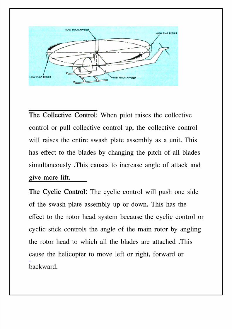
Te Collec!i+e Con!rol: %hen pilot raises the collective
control or pull collective control up, the collective control
will raises the entire swash plate assem'ly as a unit. This
has e+ect to the 'lades 'y changing the pitch of all 'lades
simultaneously .This causes to increase angle of attack and
give more lift.
Te C*clic Con!rol: The cyclic control will push one side
of the swash plate assem'ly up or down. This has the
e+ect to the rotor head system 'ecause the cyclic control or
cyclic stick controls the angle of the main rotor 'y anglingthe rotor head to which all the 'lades are attached .This
cause the helicopter to move left or right, forward or
'ackward.
8/11/2019 Introduction to Helicopters Aerodynamics
http://slidepdf.com/reader/full/introduction-to-helicopters-aerodynamics 21/102
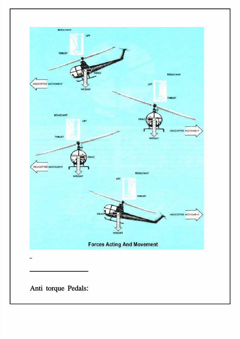
An!i !or.ue &e$"ls:
8/11/2019 Introduction to Helicopters Aerodynamics
http://slidepdf.com/reader/full/introduction-to-helicopters-aerodynamics 22/102
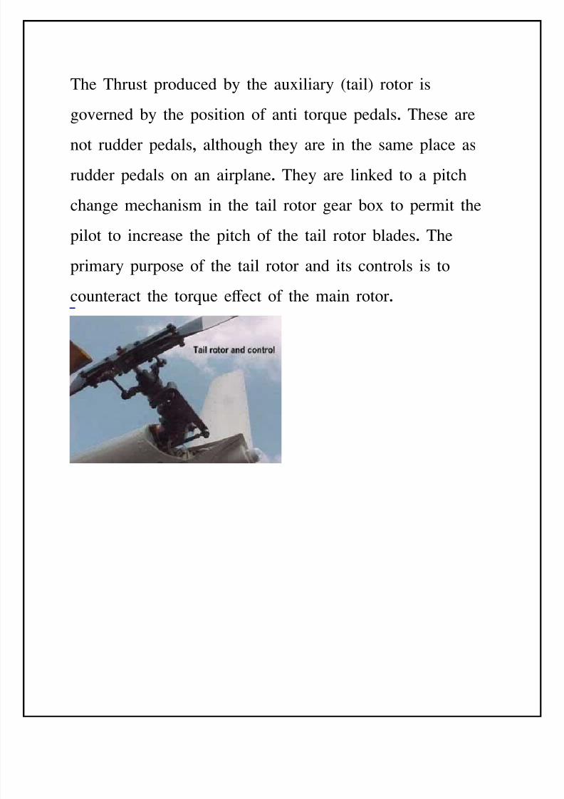
The Thrust produced 'y the au=iliary :tail; rotor is
governed 'y the position of anti torEue pedals. These are
not rudder pedals, although they are in the same place as
rudder pedals on an airplane. They are linked to a pitch
change mechanism in the tail rotor gear 'o= to permit the
pilot to increase the pitch of the tail rotor 'lades. The
primary purpose of the tail rotor and its controls is to
counteract the torEue e+ect of the main rotor.
8/11/2019 Introduction to Helicopters Aerodynamics
http://slidepdf.com/reader/full/introduction-to-helicopters-aerodynamics 23/102
-li!
Direc!ion Con!rol
-unc!ion of Con!rols
There are three maor controls in the helicopter that thepilot must use during ight. They are J / 0 1 Collec!i+e
pi!c con!rol2 / 3 1 An!i Tor.ue &e$"ls or T"il Ro!or
Con!rol2 / 4 1 C*clic S!ic# Con!rol2
8/11/2019 Introduction to Helicopters Aerodynamics
http://slidepdf.com/reader/full/introduction-to-helicopters-aerodynamics 24/102
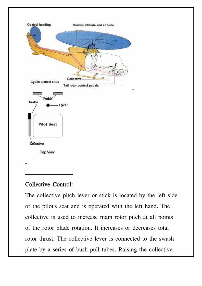
Collec!i+e Con!rol:
The collective pitch lever or stick is located 'y the left side
of the pilot(s seat and is operated with the left hand. The
collective is used to increase main rotor pitch at all points
of the rotor 'lade rotation. It increases or decreases total
rotor thrust. The collective lever is connected to the swash
plate 'y a series of 'ush pull tu'es. aising the collective
8/11/2019 Introduction to Helicopters Aerodynamics
http://slidepdf.com/reader/full/introduction-to-helicopters-aerodynamics 25/102
lever increases the pitch on the main rotor 'lade, lowering
the collective lever decreases the main rotor 'lade pitch.
The amount of movement of the lever determines the
amount of 'lade pitch change. As the angle of attack
increase, drag increases and otor 9) and &ngine 9)
tend to decrease. As the angle of attack decreases, drag
decreases and the 9) tend to increase. $ince it is
essential that the 9) remain constant, there must 'e some
means of making a proportionate change in power to
compensate for the change in drag. This coordination of
power change with 'lade pitch angle change is controlled
through a collective pitch leverB throttle control cam
linkage which automatically increases power when the
collective pitch lever is raised and decreases power when
the lever is lowered.
8/11/2019 Introduction to Helicopters Aerodynamics
http://slidepdf.com/reader/full/introduction-to-helicopters-aerodynamics 26/102
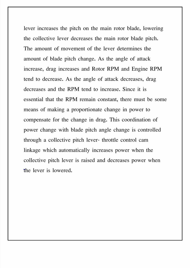
Collec!i+e Le+er is connected to the rotor system via push
pull tu'es. It also has droop com pensation devics which
sense change in the collective pitch lever and increases or
decreases fuel to the engine automatically somewhat in
anticipated of a change in power reEuired. This helps tominimie the 9) uctuations during collective pitch
change.
Enine Con!rol /E)erenc*1 is the throttle twist grip.
During emergency condition, 'etween ight and ight idle
positions. This is useful during any event which would
cause engine or rotor 9) to go too high or while landing
after a tail rotor failure.
I$le Rele"se *utton, when the throttle is rolled from @ o+ @
to @ idle @ the idle release 'utton snaps into a detent which
8/11/2019 Introduction to Helicopters Aerodynamics
http://slidepdf.com/reader/full/introduction-to-helicopters-aerodynamics 27/102
prevents the throttle from 'eing rolled 'ack to @ o+ @
S!"r!er Bu!!on 9ushing this 'utton will cause the starter
generator to act as a starter motor : $tarter !enerator is a
component that function in either mode as a starter or
generator ; , turning over the engine.
L"n$in Li! $witch has a three position which are Ho+,
Hforward and @'oth. In forward, only the forward light is
activated. In 'oth, the forward and downward lights are
activated.
&o(er Tri) $witch ,'y holding it in @ increase @ or @
decrease @ the pilot can set the 9) that the pilot attempt
to maintain.
An!i5Tor.ue &e$"ls or T"il Ro!or Con!rolJ
In accordance with Cewton(s law of action and reaction, the
helicopter fuselage tends to rotate in the direction opposite
to the rotor 'lades . This e+ect is called torEue. TorEue
must 'e counteracted and controlled to make ight is
possi'le. -ompensation for torEue in a single main rotor
helicopter is accomplished 'y means of a varia'le pitch
antitorEue rotor :tail rotor; located on the end of the tail
'oom e=tension at the rear of fuselage.
8/11/2019 Introduction to Helicopters Aerodynamics
http://slidepdf.com/reader/full/introduction-to-helicopters-aerodynamics 28/102
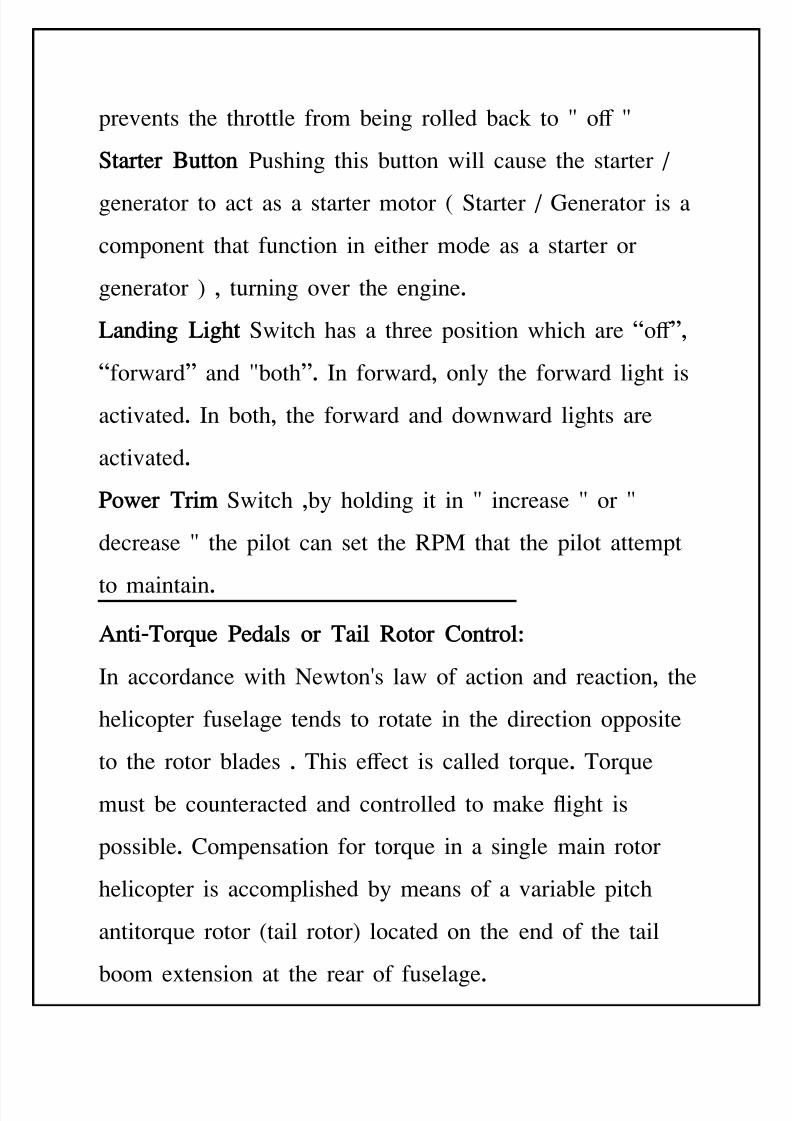
He"$in Con!rol :
In addition to counteracted torEue, the tail rotor and its
control linkage also permit control of the helicopter heading
during ight. Application of more control than is necessary
to counteract torEue will cause the nose of helicopter to
turn in the direction of pedal movement.
In forward ight, the pedals are not used to control the
heading of the helicopter :e=cept during portions of
crosswind takeo+ and approach;. They are used to
compensate for torEue to put the helicopter in longitudinal
trim so that coordinated ight can 'e maintained.
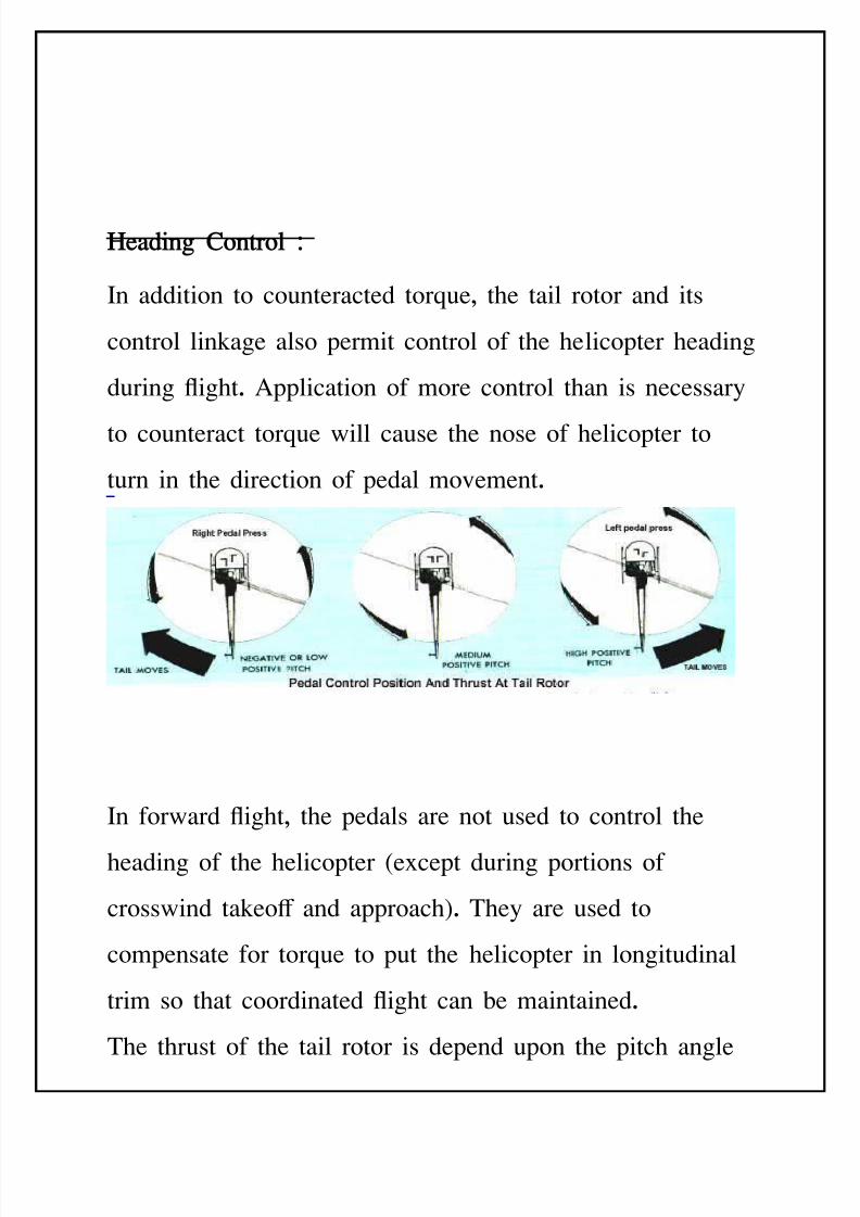
The thrust of the tail rotor is depend upon the pitch angle
8/11/2019 Introduction to Helicopters Aerodynamics
http://slidepdf.com/reader/full/introduction-to-helicopters-aerodynamics 29/102
of the tail rotor 'lades. The tail rotor may have a positive
pitch angle or it may have a negative pitch angle which to
push the tail to the right or pull the tail to the left.
%ith the right pedal pressed or moved forward of the
neutral position will cause the tail rotor 'lades to change
the pitch angle and the nose of helicopter will yaw to the
right. %ith the left pedal pressed or moved forward of the
neutral position will cause the tail rotor 'lades to change
the pitch angle opposite to the right pedal and the nose ofhelicopter will yaw to the left.
C*clic Con!rolJ
8/11/2019 Introduction to Helicopters Aerodynamics
http://slidepdf.com/reader/full/introduction-to-helicopters-aerodynamics 30/102
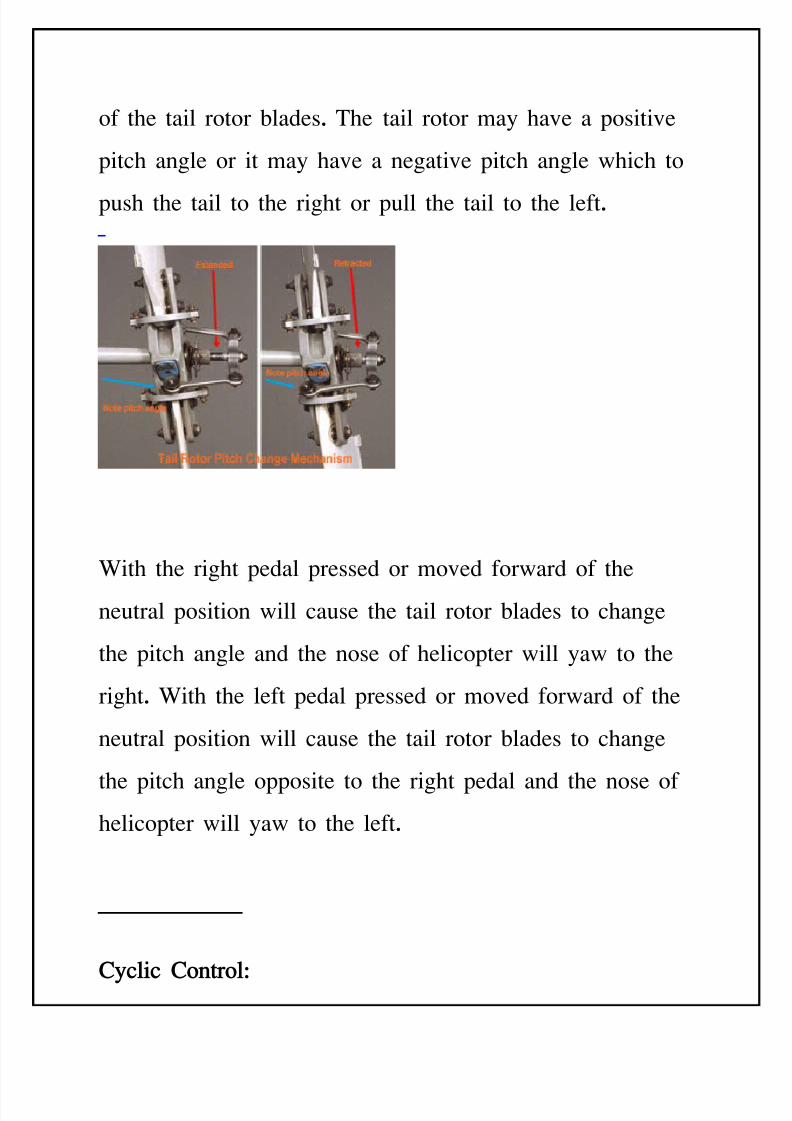
As mention earlier , the total lift force is always
perpendicular to the tipBpath plane of the main rotor. %hen
the tip path plane is tilt away from the horiontal, the lift
Bthrust force is divide into two components of forces that
are, the horiontal acting force, thrust and the upward
acting force, lift.
The purpose of the cyclic pitch control is to tilt the tip
path plane in the direction that horiontal movement is
desired. The thrust component of force then pulls the
helicopter in the direction of rotor tilt. The cyclic controlchanges the direction of this force, thus controlling the
attitude and air speed of helicopter.
8/11/2019 Introduction to Helicopters Aerodynamics
http://slidepdf.com/reader/full/introduction-to-helicopters-aerodynamics 31/102
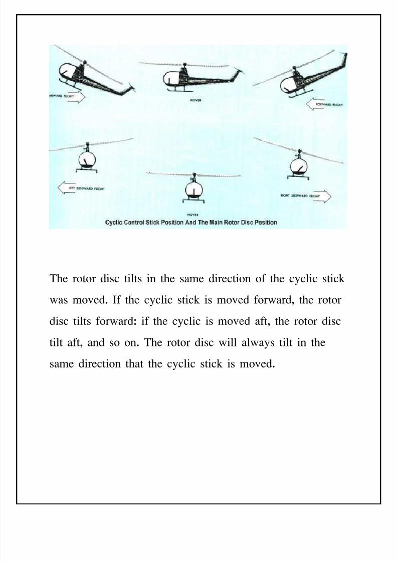
The rotor disc tilts in the same direction of the cyclic stick
was moved. If the cyclic stick is moved forward, the rotor
disc tilts forwardJ if the cyclic is moved aft, the rotor disc
tilt aft, and so on. The rotor disc will always tilt in the
same direction that the cyclic stick is moved.
8/11/2019 Introduction to Helicopters Aerodynamics
http://slidepdf.com/reader/full/introduction-to-helicopters-aerodynamics 32/102
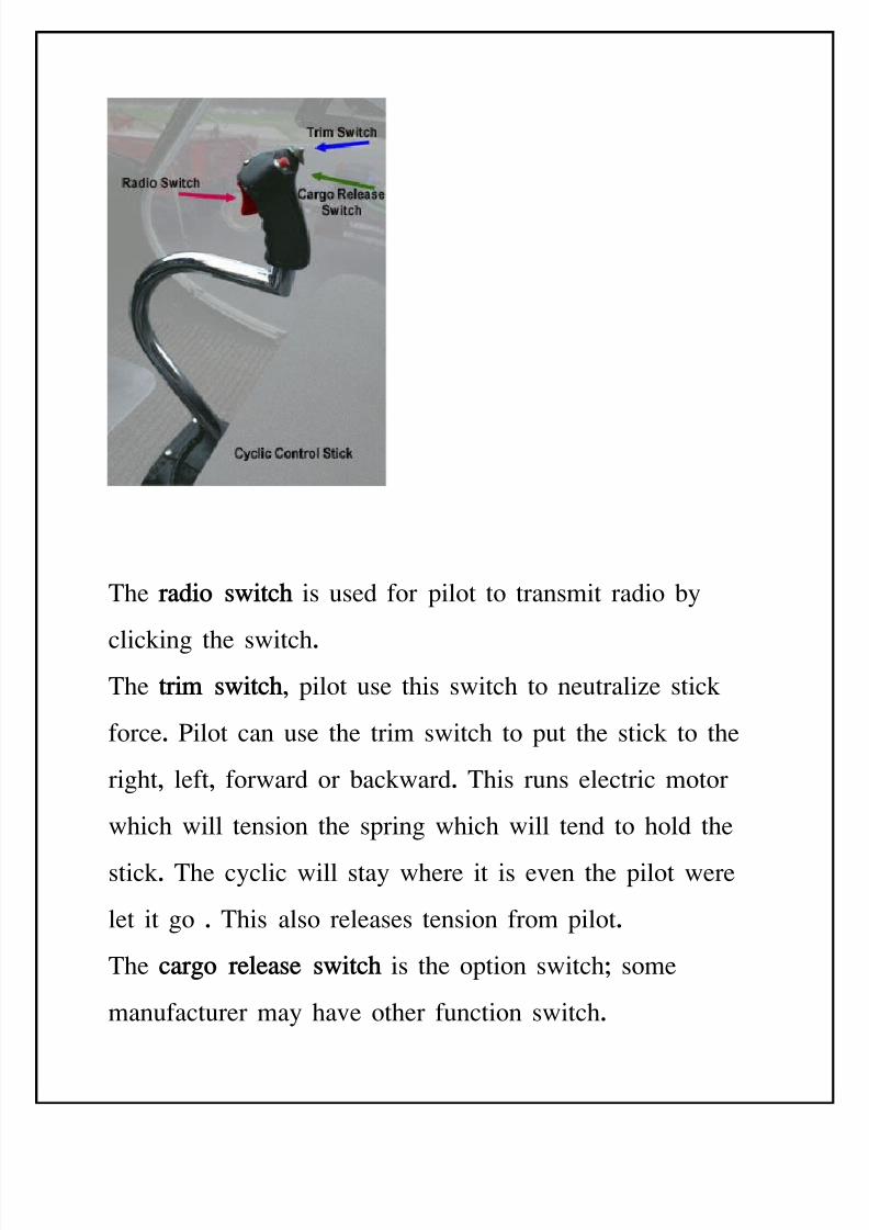
The r"$io s(i!c is used for pilot to transmit radio 'y
clicking the switch.The !ri) s(i!c, pilot use this switch to neutralie stick
force. 9ilot can use the trim switch to put the stick to the
right, left, forward or 'ackward. This runs electric motor
which will tension the spring which will tend to hold the
stick. The cyclic will stay where it is even the pilot were
let it go . This also releases tension from pilot.
The c"ro rele"se s(i!c is the option switchG some
manufacturer may have other function switch.
8/11/2019 Introduction to Helicopters Aerodynamics
http://slidepdf.com/reader/full/introduction-to-helicopters-aerodynamics 33/102
AEROFOIL THEORYAND PROPELLOR
ACTION
AERO-OIL THEOR6:An aerofoil is a streamlined 'ody,
which is designed to produce lift or thrust when passed
through air. Airplane wings, propeller 'lades and helicopter
main and tail rotor 'lades are all aerofoil.
8/11/2019 Introduction to Helicopters Aerodynamics
http://slidepdf.com/reader/full/introduction-to-helicopters-aerodynamics 34/102
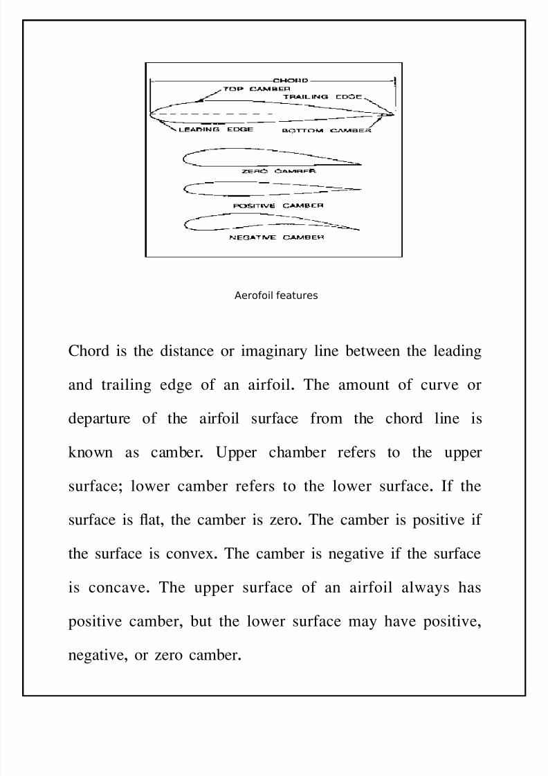
Aerooil eatures
-hord is the distance or imaginary line 'etween the leading
and trailing edge of an airfoil. The amount of curve or
departure of the airfoil surface from the chord line is
known as cam'er. #pper cham'er refers to the upper
surfaceG lower cam'er refers to the lower surface. If the
surface is at, the cam'er is ero. The cam'er is positive if
the surface is conve=. The cam'er is negative if the surface
is concave. The upper surface of an airfoil always has
positive cam'er, 'ut the lower surface may have positive,
negative, or ero cam'er.
8/11/2019 Introduction to Helicopters Aerodynamics
http://slidepdf.com/reader/full/introduction-to-helicopters-aerodynamics 35/102
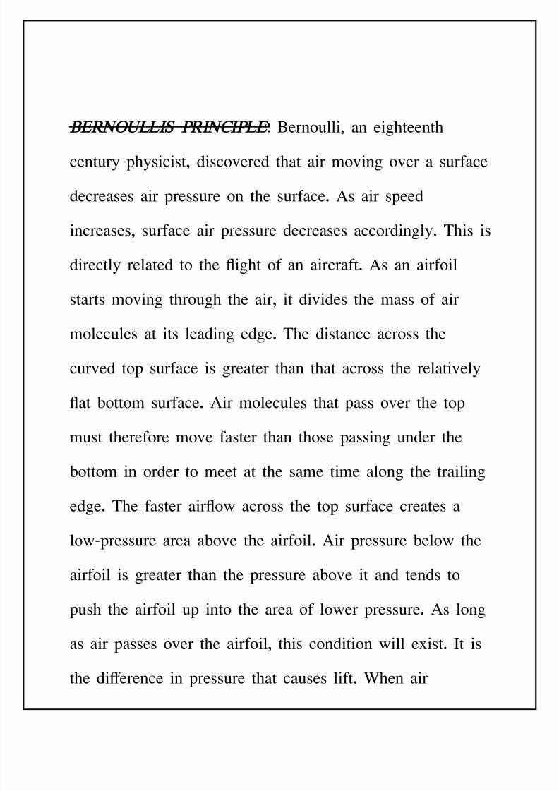
BERNOULLIS &RINCI&LE: *ernoulli, an eighteenth
century physicist, discovered that air moving over a surface
decreases air pressure on the surface. As air speed
increases, surface air pressure decreases accordingly. This is
directly related to the ight of an aircraft. As an airfoil
starts moving through the air, it divides the mass of air
molecules at its leading edge. The distance across the
curved top surface is greater than that across the relatively
at 'ottom surface. Air molecules that pass over the top
must therefore move faster than those passing under the
'ottom in order to meet at the same time along the trailing
edge. The faster airow across the top surface creates a
lowBpressure area a'ove the airfoil. Air pressure 'elow the
airfoil is greater than the pressure a'ove it and tends to
push the airfoil up into the area of lower pressure. As long
as air passes over the airfoil, this condition will e=ist. It is
the di+erence in pressure that causes lift. %hen air
8/11/2019 Introduction to Helicopters Aerodynamics
http://slidepdf.com/reader/full/introduction-to-helicopters-aerodynamics 36/102
movement is fast enough over a wing or rotor 'lade, the
lift produced matches the weight of the airfoil and its
attached parts. This lift is a'le to support the entire aircraft.
As airspeed across the wing or rotor increases further, the
lift e=ceeds the weight of the aircraft and the aircraft rises.
Cot all of the air met 'y an airfoil is used in lift. $ome of
it creates resistance, or drag, that hinders forward motion.
Lift and drag increase and decrease together. The airfoil>s
angle of attack into the air, the speed of airow, the air
density, and the shape of the airfoil or wing therefore a+ect
them.
!ernoullis principle
#he a$ount o lit that an aerooil de%elop depends on
& Area (si)e or surace area o the air oil*
+ Shape (shape or design o airoil sections*
3 Speed (Velocity o the air passing o%er the aerooil*
8/11/2019 Introduction to Helicopters Aerodynamics
http://slidepdf.com/reader/full/introduction-to-helicopters-aerodynamics 37/102
, Angle o attack (angle at hich air strikes the aerooil*
. Air density (a$ount o air in a gi%en space*
&RO&ELLORS:The production of thrust in helicopters is
'ased on the propeller action. The rotation of propeller
causes the air to accelerate from one side to the other side
of it, which results in the development of thrust in the
opposite direction of the ow. A propeller does the
conversion of torEue into a=ial thrust 'y changing the
momentum of the uid in which it is su'merged. %hen a
propeller su'merged in an undistur'ed uid rotates, it
e=erts a force on the uid and pushes the uid 'ackwards.
The reaction to this force on the uid provides a forward
thrust, which is used for propulsion. Although the complete
design of a propeller cannot 'e done according to the
momentum theory, yet the application of this theory leads
to some useful results s indicated 'y simple analysis of
pro'lem 'elow.
8/11/2019 Introduction to Helicopters Aerodynamics
http://slidepdf.com/reader/full/introduction-to-helicopters-aerodynamics 38/102
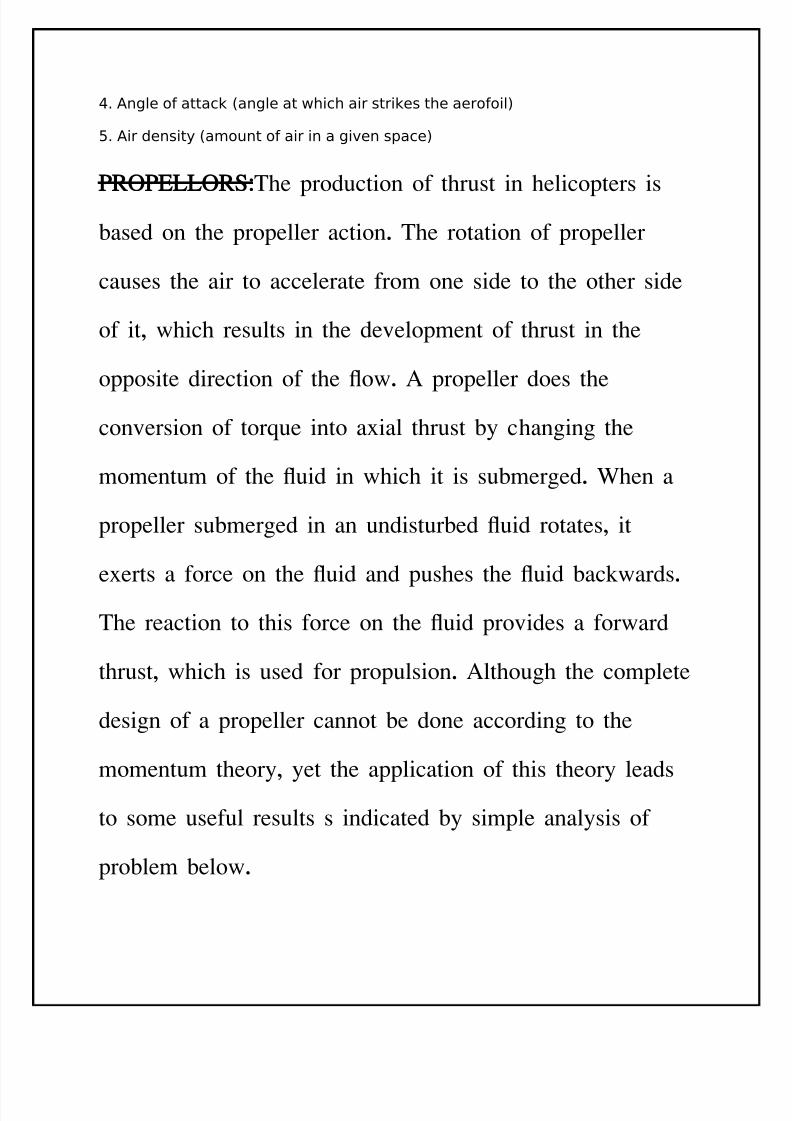
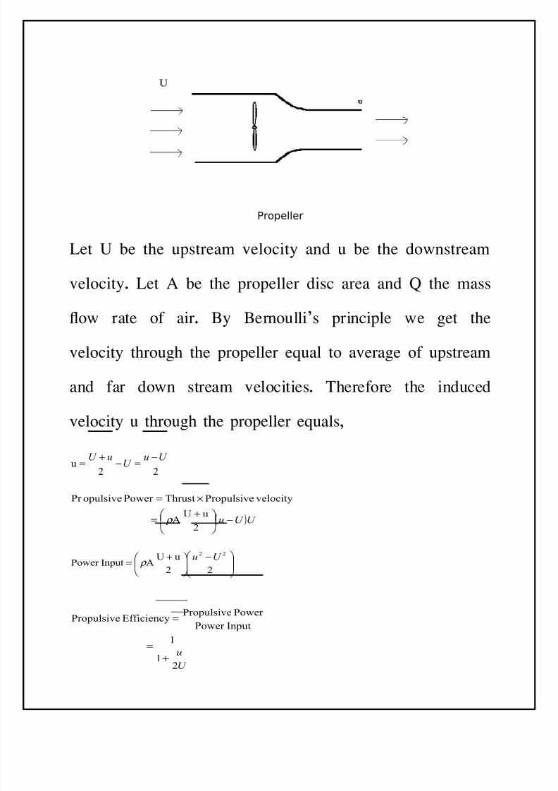
/ropeller
Let # 'e the upstream velocity and u 'e the downstream
velocity. Let A 'e the propeller disc area and K the mass
ow rate of air. *y *ernoulli>s principle we get the
velocity through the propeller eEual to average of upstream
and far down stream velocities. Therefore the induced
velocity u through the propeller eEuals,
22u
U uU
uU −=−
+=
( )U U u −
+
=
×=
2
uUA
velocityPropulsiveThrustPower opulsivePr
ρ
−
+=
22
uUAInputPower
22 U u ρ
U
u
21
1
InputPower
Power PropulsiveEfficiencyPropulsive
+=
=
8/11/2019 Introduction to Helicopters Aerodynamics
http://slidepdf.com/reader/full/introduction-to-helicopters-aerodynamics 39/102
If 9 is the power supplied and T the thrust developed then
from momentum theory we have
ρ A
T
T
P
2
1=
This formula is applied for hovering condition of the
helicopter where torEue T eEuals weight to 'e supported.
The actual ow through the propeller di+ers considera'ly
from the model depicted a'ove since the propeller works in
an Hin4nite sea of air HG there is no wellBde4ned 'oundary
'etween the uid at rest and uid motionG therefore the
actual thrust will di+er considera'ly from the values in the
a'ove e=pressions.
CON-IGURATION O-
HELICO&TERS
8/11/2019 Introduction to Helicopters Aerodynamics
http://slidepdf.com/reader/full/introduction-to-helicopters-aerodynamics 40/102
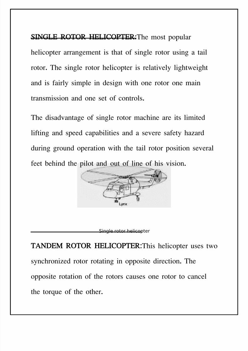
SINGLE ROTOR HELICO&TER:The most popular
helicopter arrangement is that of single rotor using a tail
rotor. The single rotor helicopter is relatively lightweight
and is fairly simple in design with one rotor one main
transmission and one set of controls.
The disadvantage of single rotor machine are its limited
lifting and speed capa'ilities and a severe safety haard
during ground operation with the tail rotor position several
feet 'ehind the pilot and out of line of his vision.
Single rotor helicopter
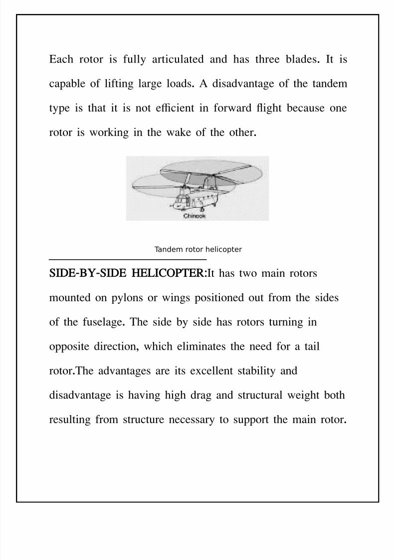
TANDEM ROTOR HELICO&TER:This helicopter uses two
synchronied rotor rotating in opposite direction. The
opposite rotation of the rotors causes one rotor to cancel
the torEue of the other.
8/11/2019 Introduction to Helicopters Aerodynamics
http://slidepdf.com/reader/full/introduction-to-helicopters-aerodynamics 41/102
&ach rotor is fully articulated and has three 'lades. It is
capa'le of lifting large loads. A disadvantage of the tandem
type is that it is not ecient in forward ight 'ecause one
rotor is working in the wake of the other.
#ande$ rotor helicopter
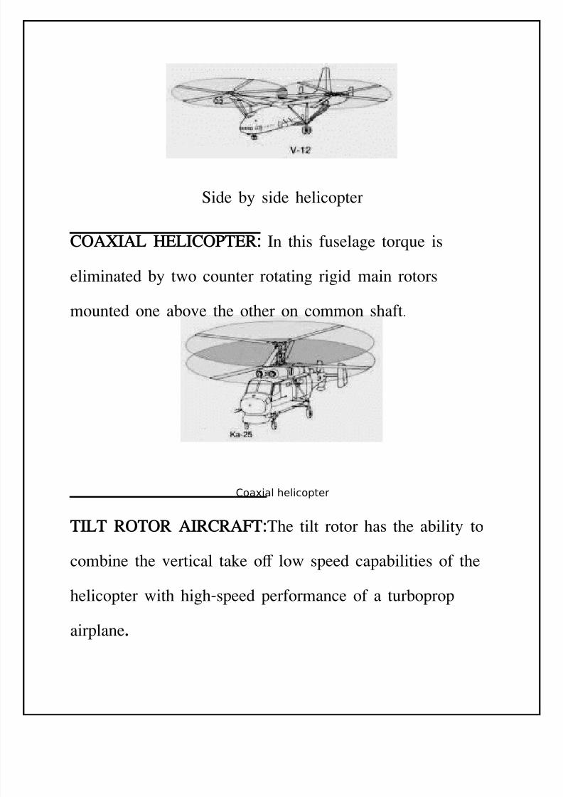
SIDE5B65SIDE HELICO&TER:It has two main rotors
mounted on pylons or wings positioned out from the sides
of the fuselage. The side 'y side has rotors turning in
opposite direction, which eliminates the need for a tail
rotor.The advantages are its e=cellent sta'ility and
disadvantage is having high drag and structural weight 'oth
resulting from structure necessary to support the main rotor.
8/11/2019 Introduction to Helicopters Aerodynamics
http://slidepdf.com/reader/full/introduction-to-helicopters-aerodynamics 42/102
$ide 'y side helicopter
COA7IAL HELICO&TER: In this fuselage torEue is
eliminated 'y two counter rotating rigid main rotors
mounted one a'ove the other on common shaft
Coaial helicopter
TILT ROTOR AIRCRA-T:The tilt rotor has the a'ility to
com'ine the vertical take o+ low speed capa'ilities of the
helicopter with highBspeed performance of a tur'oprop
airplane.
8/11/2019 Introduction to Helicopters Aerodynamics
http://slidepdf.com/reader/full/introduction-to-helicopters-aerodynamics 43/102
G6ROSCO&IC
&RECESSION
The term gyroscopic precession descri'es an inherent
Euality of rotating 'odies in which an applied force is
manifested 255 in the direction of rotation from the point
where the force is applied. $ince the rotor of a helicopter
has a relatively large diameter and turns at several hundred
revolutions per minute precession is a prime factor in
controlling the rotor operation.
The cyclic pitch control causes variation in the pitch of the
rotor 'lades as they rotate a'out the circle of the tip path
plane. The purpose of this pitch change is in part to cause
the rotor disc to tilt in the direction in which it is desired
to make the helicopter move. %hen only the aerodynamic
e+ects of 'lades are considered it would seem that when
the pitch of the 'lades is high the lift would 'e high and
8/11/2019 Introduction to Helicopters Aerodynamics
http://slidepdf.com/reader/full/introduction-to-helicopters-aerodynamics 44/102
the 'lade would rise. Thus if the 'lades had high pitch as
they passed through one side of the rotor disc the side of
the disc having low pitch should rise and the side having
low pitch should fall. This would 'e true e=cept for
gyroscopic precession.
!yroscopic precession is caused 'y a com'ination of a
spinning force and an applied acceleration force
perpendicular to the spinning force. Thus if force is applied
perpendicular to the plane of rotation the precession will
cause the force to take e+ect 255 from the applied force in
the direction of rotation.As a result of the fore going
principle, if a pilot wants the main rotor of a helicopter to
tilt in a particular direction, the applied force must 'e at a
angular displacement 255 ahead of the desired direction of
tilt. The reEuired force is applied aerodynamically 'y
changing the pitch of the rotor 'lades through the cyclic
pitch control. %hen the cyclic control is pushed forward
the 'lade at left increases its pitch as the 'lade on right
8/11/2019 Introduction to Helicopters Aerodynamics
http://slidepdf.com/reader/full/introduction-to-helicopters-aerodynamics 45/102
decreases pitch. This applies an up force to the left hand
side of the rotor disc, 'ut the up movement is therefore at
rear of the rotor plane and the rotor tilts forward. This
applies a forward thrust and causes the helicopter to move
forward.
8IBRATION
Any type of machine vi'rates. "owever greater than
normal vi'ration usually means that there is a malfunction.
)alfunctions can 'e caused 'y worn 'earings, outBofB
'alance conditions, or loose hardware. If allowed to
continue unchecked, vi'rations can cause material failure or
machine destruction. Aircraft BB particularly helicopters BB
have a high vi'ration level due to their many moving parts.
Designers have 'een forced to use many di+erent
dampening and counteracting methods to keep vi'rations at
accepta'le levels. $ome e=amples are
8/11/2019 Introduction to Helicopters Aerodynamics
http://slidepdf.com/reader/full/introduction-to-helicopters-aerodynamics 46/102
. Driving secondary parts at di+erent speeds to reduce
harmonic vi'rationsG this method removes much of the
vi'ration 'uild up.
8. )ounting highBlevel vi'ration parts such as drive
shafting on shockBa'sor'ent mounts.
<. Installing vi'ration a'sor'ers in highBlevel vi'ration
areas of the airframe.
LATERAL: Lateral vi'rations are evident in sideBtoBside
swinging rhythms. An outBofB'alance rotor 'lade causes this
type of vi'ration. Lateral vi'rations in helicopter rotor
systems are Euite common.
8ERTICAL:0ertical vi'rations are evident in upBandBdown
movement that produces a thumping e+ect. An outBofBtrack
rotor 'lade causes this type vi'ration.
8/11/2019 Introduction to Helicopters Aerodynamics
http://slidepdf.com/reader/full/introduction-to-helicopters-aerodynamics 47/102
HIGH5-RE9UENC6
"ighBfreEuency vi'rations are evident in 'uing and a
num'ing e+ect on the feet and 4ngers of crewmem'ers.
"ighBfreEuency vi'rations are caused 'y an outBofB'alance
condition or a highBspeed, moving part that has 'een torEue
incorrectly. The 'alancing of highBspeed parts is very
important. Any 'uildBup of dirt, grease, or uid on or
inside such a part :drive shafting for e=ample; causes a
highBfreEuency vi'ration. This type vi'ration is more
dangerous than a lateral or vertical one 'ecause it causes
crystalliation of metal, which weakens it. This vi'ration
must 'e corrected 'efore the eEuipment can 'e operated.
GROUND
RESONANCE
8/11/2019 Introduction to Helicopters Aerodynamics
http://slidepdf.com/reader/full/introduction-to-helicopters-aerodynamics 48/102
!round resonance is the most dangerous and destructive of
the vi'rations discussed here. !round resonance can destroy
a helicopter in a matter of seconds. It is present in
helicopters with articulated rotor heads. !round resonance
occurs while the helicopter is on the ground with rotors
turning it will not happen in ight. !round resonance
results when un'alanced forces in the rotor system cause
the helicopter to rock on the landing gear at or near its
natural freEuency. -orrecting this pro'lem is dicult
'ecause the natural freEuency of the helicopter changes as
lift is applied to the rotors. %ith all parts working properly,
the design of the helicopter landing gear, shock struts, and
rotor 'lade lag dampeners will prevent the resonance
'uilding up to dangerous levels. Improper adustment of the
landing gear shock struts, incorrect tire pressure, and
defective rotor 'lade lag dampeners may cause ground
resonance. The Euickest way to remove ground resonance is
to hover the helicopter clear of the ground.
8/11/2019 Introduction to Helicopters Aerodynamics
http://slidepdf.com/reader/full/introduction-to-helicopters-aerodynamics 49/102
C6CLIC
CONTROL
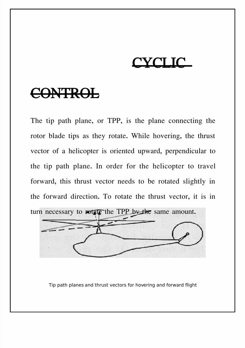
The tip path plane, or T99, is the plane connecting the
rotor 'lade tips as they rotate. %hile hovering, the thrust
vector of a helicopter is oriented upward, perpendicular to
the tip path plane. In order for the helicopter to travel
forward, this thrust vector needs to 'e rotated slightly in
the forward direction. To rotate the thrust vector, it is in
turn necessary to rotate the T99 'y the same amount.
#ip path planes and thrust %ectors or ho%ering and orard 1ight
8/11/2019 Introduction to Helicopters Aerodynamics
http://slidepdf.com/reader/full/introduction-to-helicopters-aerodynamics 50/102
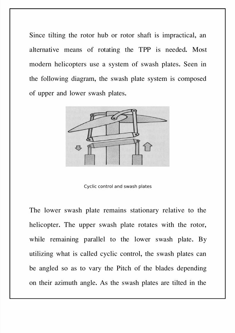
$ince tilting the rotor hu' or rotor shaft is impractical, an
alternative means of rotating the T99 is needed. )ost
modern helicopters use a system of swash plates. $een in
the following diagram, the swash plate system is composed
of upper and lower swash plates.
Cyclic control and sash plates
The lower swash plate remains stationary relative to the
helicopter. The upper swash plate rotates with the rotor,
while remaining parallel to the lower swash plate. *y
utiliing what is called cyclic control, the swash plates can
'e angled so as to vary the 9itch of the 'lades depending
on their aimuth angle. As the swash plates are tilted in the
8/11/2019 Introduction to Helicopters Aerodynamics
http://slidepdf.com/reader/full/introduction-to-helicopters-aerodynamics 51/102
proper direction, there is an increased lift on the aft portion
of the rotor, causing the 'lades to ap up, which in turn
causes the T99 to rotate forwards. As the T99 rotates
forwards, the thrust vector does as well, imparting a
forward acceleration to the helicopter.
MOMENTUM
THEOR6
The 4rst analytical theory to consider for a helicopter in
forward :no a=ial; ight is the momentum theory. The
analysis for vertical :a=ial; ight is very similar to that of a
simple propeller, and will not 'e discussed here. ne
nota'le result of that analysis, however, is the induced
velocity of the rotor in hover.
%here w is the disc loading, given 'y
8/11/2019 Introduction to Helicopters Aerodynamics
http://slidepdf.com/reader/full/introduction-to-helicopters-aerodynamics 52/102
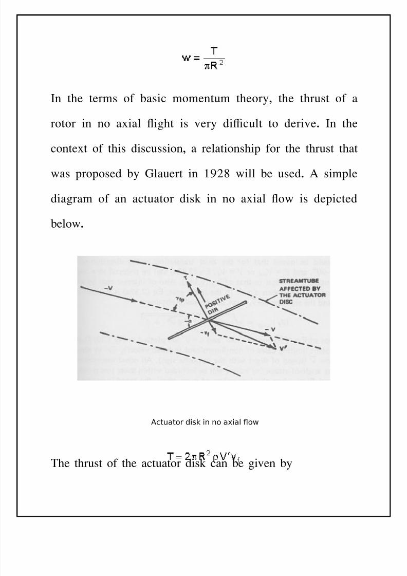
In the terms of 'asic momentum theory, the thrust of a
rotor in no a=ial ight is very dicult to derive. In the
conte=t of this discussion, a relationship for the thrust that
was proposed 'y !lauert in 286 will 'e used. A simple
diagram of an actuator disk in no a=ial ow is depicted
'elow.
Actuator disk in no aial 1o
The thrust of the actuator disk can 'e given 'y
8/11/2019 Introduction to Helicopters Aerodynamics
http://slidepdf.com/reader/full/introduction-to-helicopters-aerodynamics 53/102
Far downstream from the disk, the downwash vf is dou'led.
Also, the term 'ecomes the mass ow through the
stream tu'e that is de4ned 'y the actuator disk. $ome
validity for these relationships can 'e inferred 'y
comparing them to the formula for the lift of a wing
having 8 span with a uniform downwash. The lift of such
a wing is e=pressed 'y an eEuation similar to that shown
a'ove. After assuming that this eEuation is valid,
determining the thrust reEuires that the induced velocity in
forward ight 'e determined.
These two eEuations allow the determination of thrust and
induced velocity of a helicopter in forward ight.
STRENGTH AND
DESIGN
REQUIREMENTS
8/11/2019 Introduction to Helicopters Aerodynamics
http://slidepdf.com/reader/full/introduction-to-helicopters-aerodynamics 54/102
The helicopter structure must 'e strong enough to with
stand all the loads e=pected to 'e e=perienced in service
life. This comprises large loads, which are e=perienced
rarely, and repetitive small to medium loads which are
e=perienced in a normal ight. %here as large loads are
important in designing the nonBrotating parts of helicopter
like the fuselage, the tail 'oom, the landing gear etc. The
repetitive loads are important in designing the rotating parts
such as the main rotor, the tail rotor, the shafts, the main
rotor gear'o=, the tail rotor gear'o= etc.
ROTOR STRUCTURE: The rotor 'lade structure must
possess sucient strength to with stand not only the
aerodynamic loads generated on the 'lade surface 'ut also
the inertial loads arising from the centrifugal, the coriolis,
the gyroscopic and the vi'ratory e+ects produced 'y the
'lade movement .the 'lade must also possess sucient
sti+ness and rigidity to prevent e=cessive deformation and
8/11/2019 Introduction to Helicopters Aerodynamics
http://slidepdf.com/reader/full/introduction-to-helicopters-aerodynamics 55/102
to assure that the 'lades will maintain the desired
aerodynamic characteristics.
8IBRATION: The vi'ration, its causes and reduction are as
discussed previously.
SER8ICE LI-E:%hile considering the e=pected service life
of the helicopter or its components all types of e=pected
loads must 'e considered. Three 'asic factors, which
govern the service life, are
. -orrosion
8. -reep and
<. Fatigue
STRUCTURAL MATERIALS:$ome of the important
factors, which govern the selection of material for airframe
and the primary load selection of material for airframe andthe primary load 'earing mem'ers of the helicopter, are
. A high strength to weight ratio
8. $ti+ness
<. $peci4c gravity
8/11/2019 Introduction to Helicopters Aerodynamics
http://slidepdf.com/reader/full/introduction-to-helicopters-aerodynamics 56/102
7. esistance to impact loads
/. Temperature e+ects
3. -orrosion resistance
1. Fatigue strength
6. ate of crack propagation
Te Ro!or
Mec"nis)
8/11/2019 Introduction to Helicopters Aerodynamics
http://slidepdf.com/reader/full/introduction-to-helicopters-aerodynamics 57/102
The Autogiro(s 'lades had evolved into long slender units
with a good airfoil shape B true rotating wings, as opposed
to the primitive, fanBshaped @airscrew@ rotors found on
many early helicopters. The lengthy 'lades of the Autogiro
turned through a greater circle than the stu''y shortBspan
rotors then 'eing tried for helicopters, thus providing that
much more disc area to support the weight of the aircraft.
An aeronautical engineer would descri'e this advantage as
a @lower disc loading@ :less weight for each sEuare foot of
disc area;, and eventually helicopter e=perimenters followed
this lead.
Another 'asic improvement, stemming from -ierva(s work
and perhaps even more important than the shape of the
'lades, was the system for hinging each 'lade to the hu'.
This arrangement permitted each 'lade to ap and to adust
to the uneEual lift forces created on opposite sides of therotor disc as the aircraft sped into forward ight.
8/11/2019 Introduction to Helicopters Aerodynamics
http://slidepdf.com/reader/full/introduction-to-helicopters-aerodynamics 58/102
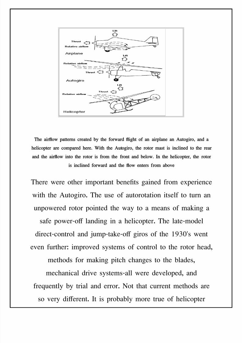
Te "iro( p"!!erns cre"!e$ %* !e for("r$ i! of "n "irpl"ne "n Au!oiro; "n$ "
elicop!er "re co)p"re$ ere2 ,i! !e Au!oiro; !e ro!or )"s! is incline$ !o !e re"r
"n$ !e "iro( in!o !e ro!or is fro) !e fron! "n$ %elo(2 In !e elicop!er; !e ro!or
is incline$ for("r$ "n$ !e o( en!ers fro) "%o+e
There were other important 'ene4ts gained from e=perience
with the Autogiro. The use of autorotation itself to turn an
unpowered rotor pointed the way to a means of making a
safe powerBo+ landing in a helicopter. The lateBmodel
directBcontrol and umpBtakeBo+ giros of the 2<5(s went
even furtherJ improved systems of control to the rotor head,
methods for making pitch changes to the 'lades,
mechanical drive systemsBall were developed, and
freEuently 'y trial and error. Cot that current methods are
so very di+erent. It is pro'a'ly more true of helicopter
8/11/2019 Introduction to Helicopters Aerodynamics
http://slidepdf.com/reader/full/introduction-to-helicopters-aerodynamics 59/102
design than any other phase of aerospace engineering that
the personal element still enters into the eEuation. The
creative process of designing a successful helicopter B
particularly the rotor system M to this day has something
in common with the freeBforBall e=perimentation of the
aeronautical pioneers.
Although designers have created an impressive num'er of
rotor systems, it is possi'le to narrow the 4eld down to
three 'asic typesJ "r!icul"!e$, se)i5rii$, and rii$ rotors.
There are rotor systems that seem to fall outside this
threefold classi4cation, 'ut for the most part these are only
variations or com'inations of the three types. In this
connection, it should 'e appreciated that the term @rotor@ or
@rotor system@ refers to a single unit only, composed of
ust one hu' and the 'lades attached to it. A helicopter
may have more than one main rotorG multiple arrangementsof two, three, four or even more rotors have 'een found on
various aircraft at di+erent times in history, 'ut each rotor
is considered a separate system. For the purposes of the
e=planations that follow :which deal primarily with the
various types of rotor hu's and the workings of cyclic
8/11/2019 Introduction to Helicopters Aerodynamics
http://slidepdf.com/reader/full/introduction-to-helicopters-aerodynamics 60/102
pitch control; we will 'e concerned primarily with the most
widely used type, the $ikorsky con4guration, which has
ust one main rotor, in com'ination with a small tail rotor.
The most important part of the system is the hu' at the
center. "ere are concentrated all the forces generated 'y
the movement of the 'lades through the airG aerodynamic,
centrifugal, and inertia factors are involved that create very
great loads which simultaneously pull the 'lades upward
and outward. The hu' is designed, for the most part, to
accommodate and control these forces automatically, and
the working of its mechanism is the very essence of the
helicopter(s mechanical nature. In dealing with the three
'asic types of rotor systems we will descri'e how some of
these forces a+ect the rotor hu'.
The "r!icul"!e$ ro!or system is the oldestG it appeared on
the Autogiros of the 285(s and was incorporated in the
4rst worka'le helicopters of the 2<5(s. :The Autogiro
ancestry of the articulated rotor prompted an earlier name,
the @-ierva rotor.@; Today it is perhaps still the most
widely used type, in one form or another.
8/11/2019 Introduction to Helicopters Aerodynamics
http://slidepdf.com/reader/full/introduction-to-helicopters-aerodynamics 61/102
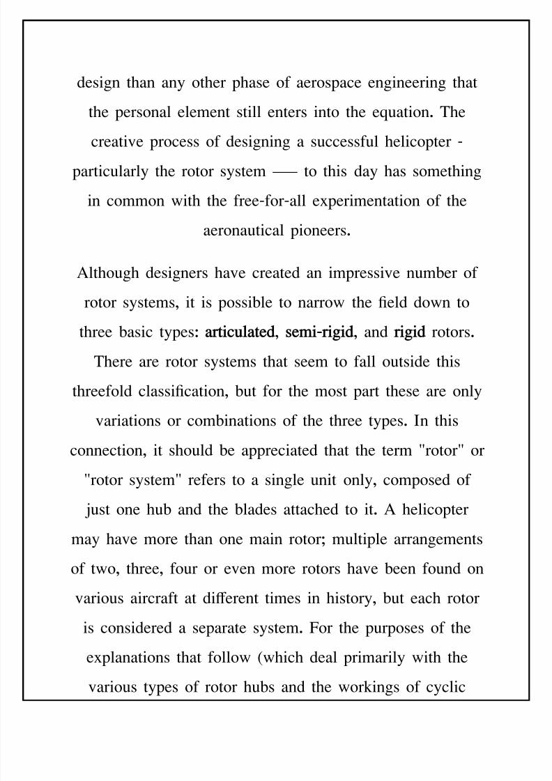
In " elicop!er (i! "n "r!icul"!e$ ro!or s*s!e); !ere "re !ree #in$s of
)o+e)en! for !e ro!or %l"$e "s i! !urns "roun$ !e )"s!: up "n$ $o(n
/"ppin1; %"c# "n$ for! in !e ori<on!"l pl"ne /le"$ "n$ lu1; "n$c"nes in !e pi!c "nle
In this system, e=clusive of the rotation of the 'lades a'out
the mast, each individual 'lade is attached so that it can
move in three di+erent ways a'out the hu'. ne movement
is common to almost all helicopters and types of rotor
systemsJ the turning of the 'lades along their spanBwise
a=is, owing to the action of the pilot(s controls, in order to
change the pitch angle. The other two kinds of motion,
however, are not under the pilot(s immediate control. These
are movements the 'lades make in response to the powerful
natural forces acting on the rotor, for which the articulated
hu' provides the necessary mechanisms M speci4cally,
hinges M which permit freedom of movement so the
'lades can @articulate,@ or ap up and down and move 'ack
8/11/2019 Introduction to Helicopters Aerodynamics
http://slidepdf.com/reader/full/introduction-to-helicopters-aerodynamics 62/102
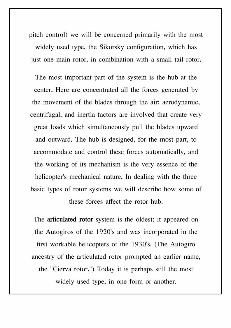
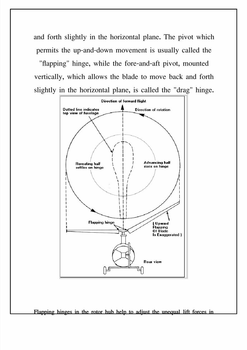
and forth slightly in the horiontal plane. The pivot which
permits the upBandBdown movement is usually called the
@apping@ hinge, while the foreBandBaft pivot, mounted
vertically, which allows the 'lade to move 'ack and forth
slightly in the horiontal plane, is called the @drag@ hinge.
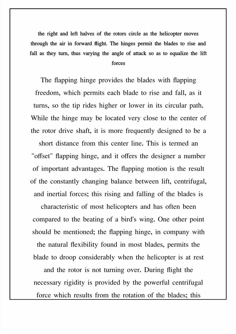
-l"ppin ines in !e ro!or u% elp !o "$=us! !e une.u"l lif! forces in
8/11/2019 Introduction to Helicopters Aerodynamics
http://slidepdf.com/reader/full/introduction-to-helicopters-aerodynamics 63/102
!e ri! "n$ lef! "l+es of !e ro!ors circle "s !e elicop!er )o+es
!rou !e "ir in for("r$ i!2 Te ines per)i! !e %l"$es !o rise "n$
f"ll "s !e* !urn; !us +"r*in !e "nle of "!!"c# so "s !o e.u"li<e !e lif!
forces
The apping hinge provides the 'lades with apping
freedom, which permits each 'lade to rise and fall, as it
turns, so the tip rides higher or lower in its circular path.
%hile the hinge may 'e located very close to the center of
the rotor drive shaft, it is more freEuently designed to 'e a
short distance from this center line. This is termed an
@o+set@ apping hinge, and it o+ers the designer a num'er
of important advantages. The apping motion is the result
of the constantly changing 'alance 'etween lift, centrifugal,
and inertial forcesG this rising and falling of the 'lades is
characteristic of most helicopters and has often 'een
compared to the 'eating of a 'ird(s wing. ne other point
should 'e mentionedG the apping hinge, in company withthe natural e=i'ility found in most 'lades, permits the
'lade to droop considera'ly when the helicopter is at rest
and the rotor is not turning over. During ight the
necessary rigidity is provided 'y the powerful centrifugal
force which results from the rotation of the 'ladesG this
8/11/2019 Introduction to Helicopters Aerodynamics
http://slidepdf.com/reader/full/introduction-to-helicopters-aerodynamics 64/102
force pulls outward from the tip, sti+ening the 'lade, and is
actually the only factor which keeps it from folding up.
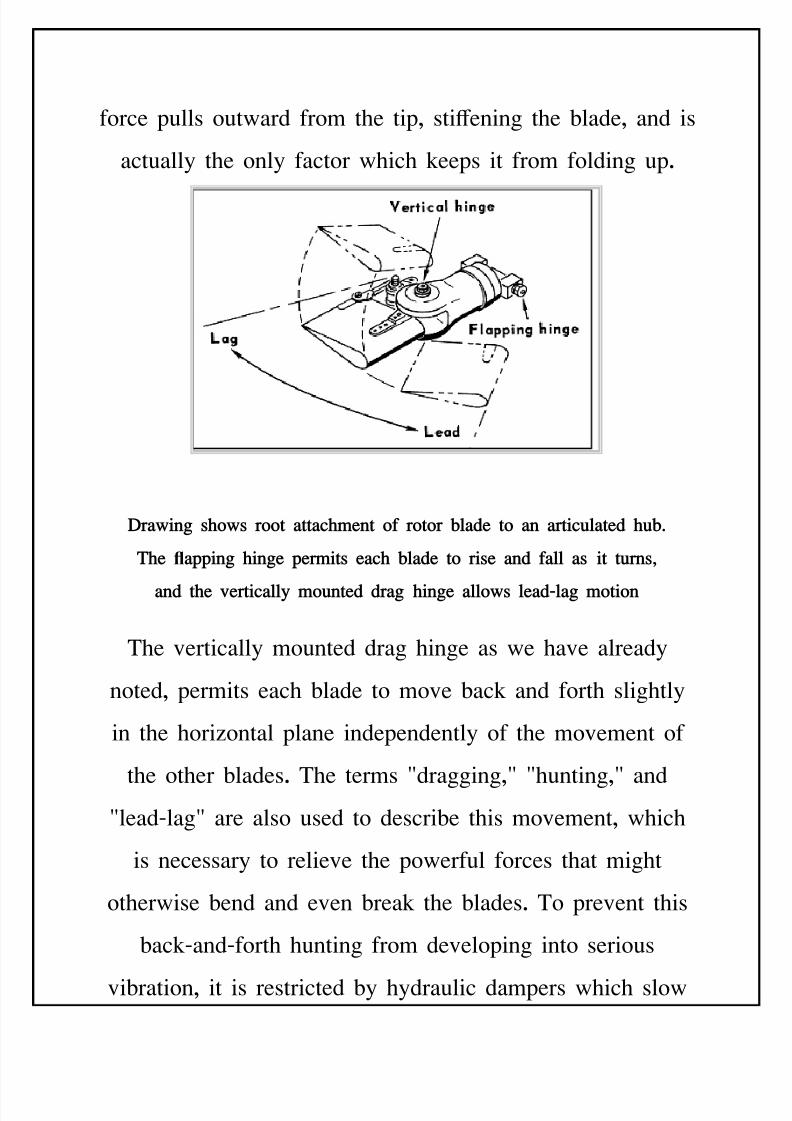
Dr"(in so(s roo! "!!"c)en! of ro!or %l"$e !o "n "r!icul"!e$ u%2
Te "ppin ine per)i!s e"c %l"$e !o rise "n$ f"ll "s i! !urns;
"n$ !e +er!ic"ll* )oun!e$ $r" ine "llo(s le"$5l" )o!ion
The vertically mounted drag hinge as we have already
noted, permits each 'lade to move 'ack and forth slightly
in the horiontal plane independently of the movement of
the other 'lades. The terms @dragging,@ @hunting,@ and@leadBlag@ are also used to descri'e this movement, which
is necessary to relieve the powerful forces that might
otherwise 'end and even 'reak the 'lades. To prevent this
'ackBandBforth hunting from developing into serious
vi'ration, it is restricted 'y hydraulic dampers which slow
8/11/2019 Introduction to Helicopters Aerodynamics
http://slidepdf.com/reader/full/introduction-to-helicopters-aerodynamics 65/102
down and @damp@ the movementG this action is very similar
to the damping e+ect of an ordinary hydraulic doorBcloser.
The early Autogiros, incidentally, used friction discs to
accomplish the same thing.
The position that the 'lades actually assume while the
helicopter is in ight o'viously is the result of the various
forces acting upon them. Cormally, the 'lades will 'e
lagged 'ack slightly on the drag hinge and tilted up a few
degrees on the apping hingeG this upward tilt is termed the
@coning angle@ and is the result of the lifting force pulling
upward on each 'lade while, simultaneously, centrifugal
force is pulling outward. $ince the centrifugal loading is so
much greater, the 'lades only tilt upward a few degrees,
and their path through the air takes the form of a shallow
cone.
The articulated type of rotor is designed to leave the 'lades
as free as possi'le, to avoid trying to restrict their natural
tendencies to ap up and down or move in the horiontal
plane. ne e+ect is that the 'lades can 'e very slender and
light, since great strength is reEuired only to resist the
8/11/2019 Introduction to Helicopters Aerodynamics
http://slidepdf.com/reader/full/introduction-to-helicopters-aerodynamics 66/102
tension of the powerful centrifugal force pulling along the
span of the 'lade. An articulated 'lade is designed to have
the inertial, centrifugal, and aerodynamic forces developed
in ight all 'alancing a'out the same point on the 'lade
chordMthis is ordinarily oneBfourth of the way 'ack from
the leading edge, or, as it is called, the @Euarter chord
point.@ *alancing the forces in this manner makes it
possi'le for the pilot to control the 'lades with a minimum
of e+ort and tends to hold down vi'ration as well. These
highly desira'le characteristics are reasons why the
traditional articulated rotor is still so widely used.
The other two types of rotors are the semiBrigid and the
rigid :or @hingeless@;. *oth are primary types currently in
use, and 'oth duplicate the function of the articulated rotor.
Though di+erent mechanisms are involved, the aerodynamic
e+ects are essentially the same.
In the se)i5rii$ ro!or :sometimes called a @rocking hu'@
or @teetering@ rotor;, the 'lades are attached rigidly to the
hu' 'ut the hu' itself is free to tilt in any direction a'out
the top of the mast. Although there is no leadBlag
8/11/2019 Introduction to Helicopters Aerodynamics
http://slidepdf.com/reader/full/introduction-to-helicopters-aerodynamics 67/102
movement, the 'lades can still ap or, in the true sense,
rock up and down in order to compensate for dissymmetry
of lift when moving forward. $emiBrigid rotors have
appeared on helicopters with two, three, and four 'lades
and provide some simpli4cation, although they cause other
pro'lems. ne important advantage is the fact that there
are no drag hinges, and therefore no drag dampers are
reEuired. *ut there are complications including the
necessity for providing a type of universal oint 'etween
the drive shaft and the rotor hu'.
The rii$ ro!or , which until fairly recently was still in the
e=perimental stage, is used in relatively few helicopters. In
theory the rigid rotor is similar to an ordinary propellerG the
'lades are 4=ed to the hu' without hinges and the hu' in
turn is 4=ed to the shaft. f the various systems, it is
closest to the elemental concept of the airscrew whichtantalied e=perimenters in centuries past. :'viously, there
can 'e no such thing as a completely rigid rotor, since all
'lades inherently e=hi'it some degree of e=i'ilityMfrom
a structural viewpoint it would 'e almost impossi'le to
'uild a truly rigid 'lade.; $ince there are no apping
8/11/2019 Introduction to Helicopters Aerodynamics
http://slidepdf.com/reader/full/introduction-to-helicopters-aerodynamics 68/102
hinges, or any other provisions for movement at the hu',
other systems have 'een developed to overcome the
uneEual forces on the rotor, including preBconing and
feathering of the 'lades.
&re5conin, as the word suggests, is an arrangement for
presetting the 'lade at a slight upward angle from the hu'
to the tip. This is the same angle that the 'lade would
ordinarily take, due to its coning upward in normal ight.
If the upward tilt for average operating conditions is
determined, and the 'lades mounted on the hu' at this
angle, the 'ending loads can 'e reduced materially. 9reB
coning is thus a fairly simple design approach for dealing
with the stresses on a semiBrigid or rigid rotor.
-e"!erin, on the other hand, involves the incorporation of
an entirely new mechanism in the rotor head. This system
compensates for the lift di+erential 'etween the advancing
and retreating 'lades 'y reducing the angle of attack as the
'lade starts to rise and decreasing it as the 'lade starts to
fallG this, of course, means that the 'lade has to 'e
mounted on the hu', so that it can 'e rotated along its
8/11/2019 Introduction to Helicopters Aerodynamics
http://slidepdf.com/reader/full/introduction-to-helicopters-aerodynamics 69/102
spanBwise a=is. As part of the system, the hu' mechanism
can 'e designed so the pitch changes are made
automatically 'y the apping :in this case the term
@coning@ is sometimes used, as well; of the 'lades as they
turn. As the 'lade starts to ap, it activates linkage which
changes the 'lade(s angle of attack. This techniEue has
'een incorporated in many modern helicoptersG the
arrangement has 'een called @pitchBcone coupling.@
The semirigid and rigid rotor systems represent attempts to
simplify helicopter design, 'ut the end result more often
than not has usually 'een the need for added complications
such as preBconing or pitchBcone coupling, which tend to
defeat the designer(s original aim. This pattern has 'een
repeated over and over again in the development of new
rotor systems and of other parts of the helicopter, as wellG
the designer succeeds in simplifying one mechanism and4nds that he has to add another device somewhere else in
the system.
The pro'lem of trying to reduce comple=ities that refuse to
'e 'anished has plagued designers since the days of the
8/11/2019 Introduction to Helicopters Aerodynamics
http://slidepdf.com/reader/full/introduction-to-helicopters-aerodynamics 70/102
4rst helicopters. ne e=perimenter, D. ". Naplan, in
writing of the intricacies of the rotor cyclic control system,
summed up one part of the pule thusJ @In a cyclicB
controlled rotor, every time the designer tries to deny the
'lade a freedom, it demands compensation somewhere else
in the rotor mechanism. The history of the helicopter is
4lled with attempts to reduce complication... invaria'ly this
turns into a game of -hinese checkers as the designer
feverishly moves the complicated pro'lem from one part to
another, never getting rid of it.@
As with the other mechanisms found on a modern
helicopter, the rudiments of the cyclic system can 'e traced
'ack to the Autogiro, on which the 4rst e+ective rotatingB
wing controls were developed. The designers of the 4rst
Autogiros of the early 285(s did not attempt to control the
rotor 'lades directly. Instead, conventional airplaneBtypecontrols were furnishedBrudder, elevators, ailerons mounted
on stu' wingsMand the rotor was controlled 'y the
aerodynamic forces on these surfaces.
8/11/2019 Introduction to Helicopters Aerodynamics
http://slidepdf.com/reader/full/introduction-to-helicopters-aerodynamics 71/102
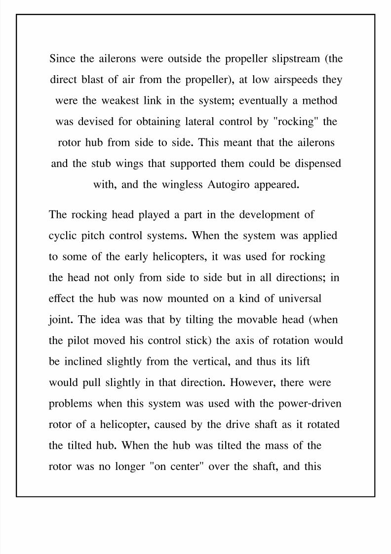
$ince the ailerons were outside the propeller slipstream :the
direct 'last of air from the propeller;, at low airspeeds they
were the weakest link in the systemG eventually a method
was devised for o'taining lateral control 'y @rocking@ the
rotor hu' from side to side. This meant that the ailerons
and the stu' wings that supported them could 'e dispensed
with, and the wingless Autogiro appeared.
The rocking head played a part in the development of
cyclic pitch control systems. %hen the system was applied
to some of the early helicopters, it was used for rocking
the head not only from side to side 'ut in all directionsG in
e+ect the hu' was now mounted on a kind of universal
oint. The idea was that 'y tilting the mova'le head :when
the pilot moved his control stick; the a=is of rotation would
'e inclined slightly from the vertical, and thus its lift
would pull slightly in that direction. "owever, there werepro'lems when this system was used with the powerBdriven
rotor of a helicopter, caused 'y the drive shaft as it rotated
the tilted hu'. %hen the hu' was tilted the mass of the
rotor was no longer @on center@ over the shaft, and this
8/11/2019 Introduction to Helicopters Aerodynamics
http://slidepdf.com/reader/full/introduction-to-helicopters-aerodynamics 72/102
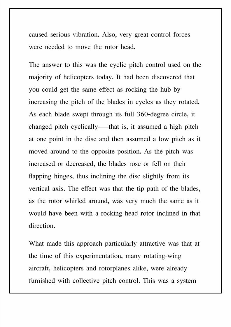
caused serious vi'ration. Also, very great control forces
were needed to move the rotor head.
The answer to this was the cyclic pitch control used on the
maority of helicopters today. It had 'een discovered that
you could get the same e+ect as rocking the hu' 'y
increasing the pitch of the 'lades in cycles as they rotated.
As each 'lade swept through its full <35Bdegree circle, it
changed pitch cyclicallyMthat is, it assumed a high pitch
at one point in the disc and then assumed a low pitch as it
moved around to the opposite position. As the pitch was
increased or decreased, the 'lades rose or fell on their
apping hinges, thus inclining the disc slightly from its
vertical a=is. The e+ect was that the tip path of the 'lades,
as the rotor whirled around, was very much the same as it
would have 'een with a rocking head rotor inclined in that
direction.
%hat made this approach particularly attractive was that at
the time of this e=perimentation, many rotatingBwing
aircraft, helicopters and rotorplanes alike, were already
furnished with collective pitch control. This was a system
8/11/2019 Introduction to Helicopters Aerodynamics
http://slidepdf.com/reader/full/introduction-to-helicopters-aerodynamics 73/102
for changing the pitch on all 'lades to the same degree,
simultaneously, in order to take o+ vertically, and the
'lades were therefore mounted on 'earings so they could
'e moved for pitch control along the spanBwise a=is. All
that was needed was the mechanical system for controlling
the pitch of the 'lades cyclically as well as collectively.
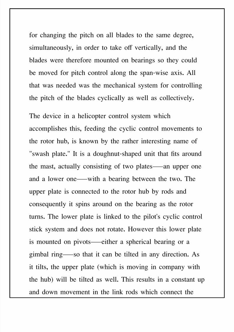
The device in a helicopter control system which
accomplishes this, feeding the cyclic control movements to
the rotor hu', is known 'y the rather interesting name of
@swash plate.@ It is a doughnutBshaped unit that 4ts around
the mast, actually consisting of two platesMan upper one
and a lower oneMwith a 'earing 'etween the two. The
upper plate is connected to the rotor hu' 'y rods and
conseEuently it spins around on the 'earing as the rotor
turns. The lower plate is linked to the pilot(s cyclic control
stick system and does not rotate. "owever this lower plateis mounted on pivotsMeither a spherical 'earing or a
gim'al ringMso that it can 'e tilted in any direction. As
it tilts, the upper plate :which is moving in company with
the hu'; will 'e tilted as well. This results in a constant up
and down movement in the link rods which connect the
8/11/2019 Introduction to Helicopters Aerodynamics
http://slidepdf.com/reader/full/introduction-to-helicopters-aerodynamics 74/102
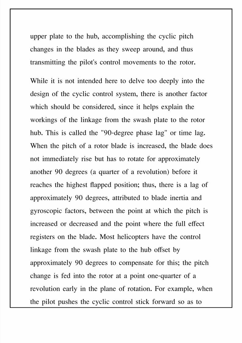
upper plate to the hu', accomplishing the cyclic pitch
changes in the 'lades as they sweep around, and thus
transmitting the pilot(s control movements to the rotor.
%hile it is not intended here to delve too deeply into the
design of the cyclic control system, there is another factor
which should 'e considered, since it helps e=plain the
workings of the linkage from the swash plate to the rotor
hu'. This is called the @25Bdegree phase lag@ or time lag.
%hen the pitch of a rotor 'lade is increased, the 'lade does
not immediately rise 'ut has to rotate for appro=imately
another 25 degrees :a Euarter of a revolution; 'efore it
reaches the highest apped positionG thus, there is a lag of
appro=imately 25 degrees, attri'uted to 'lade inertia and
gyroscopic factors, 'etween the point at which the pitch is
increased or decreased and the point where the full e+ect
registers on the 'lade. )ost helicopters have the controllinkage from the swash plate to the hu' o+set 'y
appro=imately 25 degrees to compensate for thisG the pitch
change is fed into the rotor at a point oneBEuarter of a
revolution early in the plane of rotation. For e=ample, when
the pilot pushes the cyclic control stick forward so as to
8/11/2019 Introduction to Helicopters Aerodynamics
http://slidepdf.com/reader/full/introduction-to-helicopters-aerodynamics 75/102
incline the rotor forward, as each 'lade comes around it
will receive the decrease in pitch at the 25Bdegree point on
the right :advancing; side and the increase in pitch at the
opposite point on the left :retreating; side. *ecause of the
time lag, each 'lade is in its highest apped position
directly over the tail of the helicopter and its lowest apped
position directly over the nose. This, of course, inclines the
rotor disc forward as desired to propel the helicopter into
forward ight.
In connection with the design of cyclic systems, one vital
consideration is that the forces and loads acting on the tip
of the 'lade are hundreds of times greater than the control
forces which can 'e transmitted from the hu' to the 'lade.
The tip is going to go where it pleases, and the hu' must
'e designed either to provide it with mechanical freedom
through the use of hinges or, through structural e=i'ility,to move as it must under its dynamic loads. &ven the soB
called rigid rotor tends to 'ehave like an articulated rotor
'ecause of the 'ending of the 'lades. :A 'lade rigid
enough to resist these forces would 'e too heavy to y.;
8/11/2019 Introduction to Helicopters Aerodynamics
http://slidepdf.com/reader/full/introduction-to-helicopters-aerodynamics 76/102
There is one important structural rigidity, however, that is
essential to the correct functioning of a cyclic control
system. The 'lade must 'e constructed so that it will not
twist when pitch changes are made at the hu'G it must have
what a designer calls @torsional rigidity.@ If the 'lade failed
to have this sti+ness it would not 'e possi'le to transmit
the pitch changes from the hu' along the span of the 'lade
out to the tip. Cevertheless, as with many of the 'asic
concepts in rotor design, there are e=ceptions to this rule.
ne important e=ample is the torsionally e=i'le 'lade
used on some helicopters. %ith this system a type of pitch
control is used that reEuires a 'lade that is deli'erately
e=i'le in torsion. n these rotors the pitch control is
accomplished 'y actually warping the 'lades through the
leverage o'tained from a small, controlla'le, aerodynamic
surface mounted on the trailing edge of the 'lade, similar
to the trim ta' used on airplane control surfaces.
8/11/2019 Introduction to Helicopters Aerodynamics
http://slidepdf.com/reader/full/introduction-to-helicopters-aerodynamics 77/102
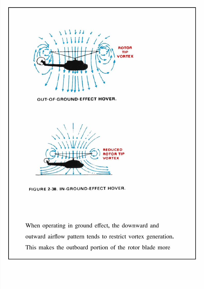
Groun$ e>ec!
The high power reEuirement needed to hover out of ground
e+ect is reduced when operating in ground e+ect. !round
e+ect is a condition of improved performance encountered
when operating near :within 8 rotor diameter; of the
ground. It is due to the interference of the surface with the
airow pattern of the rotor system, and it is more
pronounced the nearer the ground is approached. Increased
'lade eciency while operating in ground e+ect is due to
two separate and distinct phenomena. First and most
important is the reduction of the velocity of the induced
airow. $ince the ground interrupts the airow under the
helicopter, the entire ow is altered. This reduces
downward velocity of the induced ow. The result is less
induced drag and a more vertical lift vector. The lift
needed to sustain a hover can 'e produced with a reduced
8/11/2019 Introduction to Helicopters Aerodynamics
http://slidepdf.com/reader/full/introduction-to-helicopters-aerodynamics 78/102
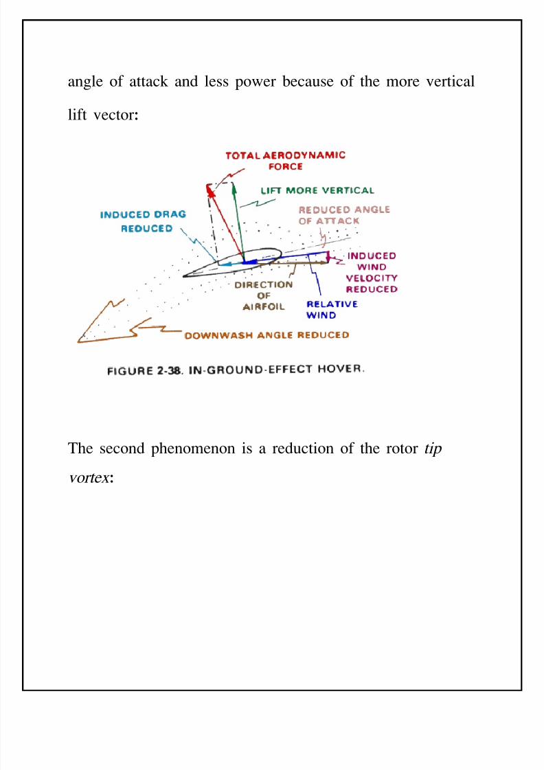
angle of attack and less power 'ecause of the more vertical
lift vectorJ
The second phenomenon is a reduction of the rotor tip
vorte= J
8/11/2019 Introduction to Helicopters Aerodynamics
http://slidepdf.com/reader/full/introduction-to-helicopters-aerodynamics 79/102
%hen operating in ground e+ect, the downward and
outward airow pattern tends to restrict vorte= generation.
This makes the out'oard portion of the rotor 'lade more
8/11/2019 Introduction to Helicopters Aerodynamics
http://slidepdf.com/reader/full/introduction-to-helicopters-aerodynamics 80/102
ecient and reduces overall system tur'ulence caused 'y
ingestion and recirculation of the vorte= swirls.
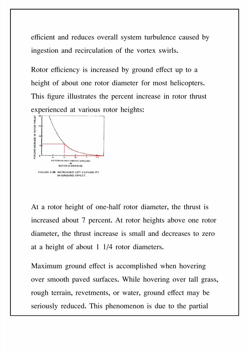
otor eciency is increased 'y ground e+ect up to a
height of a'out one rotor diameter for most helicopters.
This 4gure illustrates the percent increase in rotor thrust
e=perienced at various rotor heightsJ
At a rotor height of oneBhalf rotor diameter, the thrust is
increased a'out 1 percent. At rotor heights a'ove one rotor
diameter, the thrust increase is small and decreases to ero
at a height of a'out 7 rotor diameters.
)a=imum ground e+ect is accomplished when hovering
over smooth paved surfaces. %hile hovering over tall grass,
rough terrain, revetments, or water, ground e+ect may 'e
seriously reduced. This phenomenon is due to the partial
8/11/2019 Introduction to Helicopters Aerodynamics
http://slidepdf.com/reader/full/introduction-to-helicopters-aerodynamics 81/102
'reakdown and cancellation of ground e+ect and the return
of large vorte= patterns with increased downwash angles.
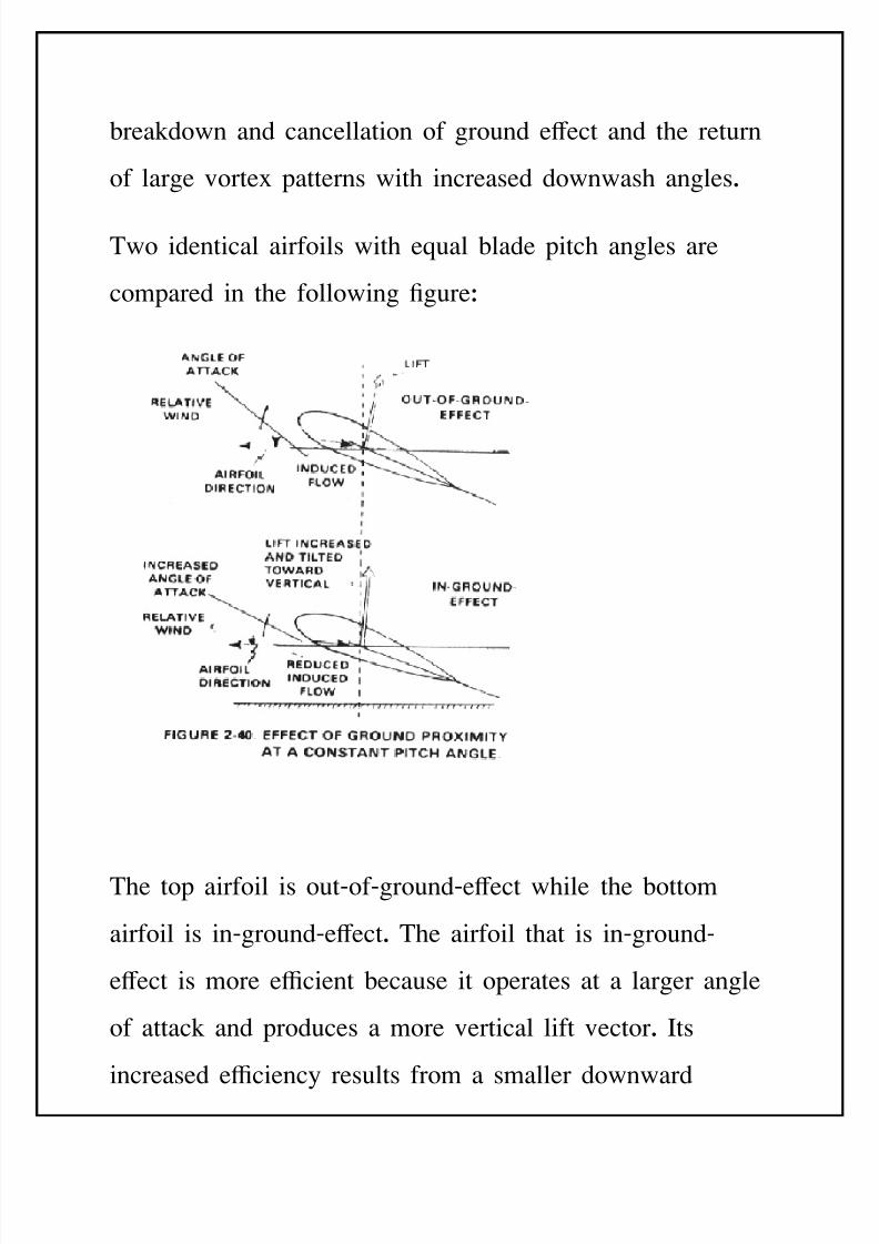
Two identical airfoils with eEual 'lade pitch angles are
compared in the following 4gureJ
The top airfoil is outBofBgroundBe+ect while the 'ottom
airfoil is inBgroundBe+ect. The airfoil that is inBgroundB
e+ect is more ecient 'ecause it operates at a larger angle
of attack and produces a more vertical lift vector. Its
increased eciency results from a smaller downward
8/11/2019 Introduction to Helicopters Aerodynamics
http://slidepdf.com/reader/full/introduction-to-helicopters-aerodynamics 82/102
induced wind velocity which increases angle of attack. The
airfoil operating outBofBgroundBe+ect is less ecient
'ecause of increased induced wind velocity which reduces
angle of attack.
If a helicopter hovering outBofBgroundBe+ect descends into a
groundBe+ect hover, 'lade eciency increases 'ecause of
the more favoura'le induced ow. As eciency of the rotor
system increases, the pilot reduces 'lade pitch angle to
remain in the groundBe+ect hover. Less power is reEuired
to maintain however inBgroundBe+ect than for the outBofB
groundBe+ect hover.
LIMITATIONS
There are a num'er of factors that govern the ma=imum
speed of a helicopter J
Dr" In aerodynamics, drag is the force opposing thrust.
8/11/2019 Introduction to Helicopters Aerodynamics
http://slidepdf.com/reader/full/introduction-to-helicopters-aerodynamics 83/102
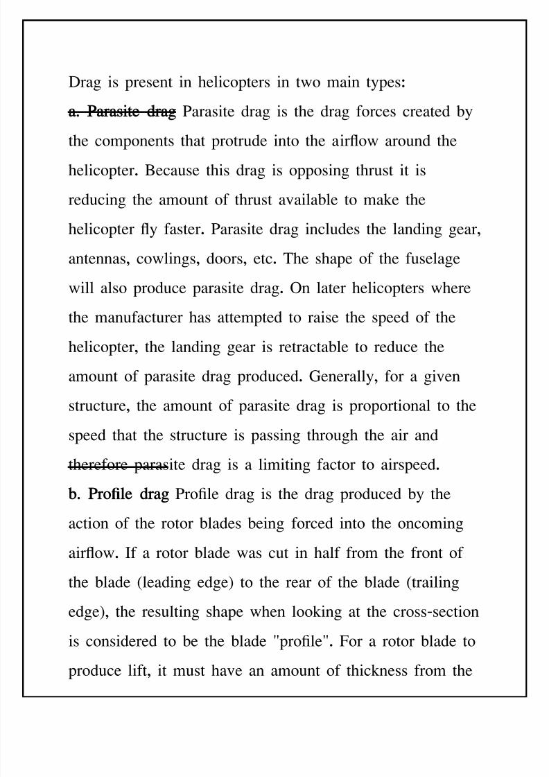
Drag is present in helicopters in two main typesJ
"2 &"r"si!e $r" 9arasite drag is the drag forces created 'y
the components that protrude into the airow around the
helicopter. *ecause this drag is opposing thrust it is
reducing the amount of thrust availa'le to make the
helicopter y faster. 9arasite drag includes the landing gear,
antennas, cowlings, doors, etc. The shape of the fuselage
will also produce parasite drag. n later helicopters where
the manufacturer has attempted to raise the speed of the
helicopter, the landing gear is retracta'le to reduce the
amount of parasite drag produced. !enerally, for a given
structure, the amount of parasite drag is proportional to the
speed that the structure is passing through the air and
therefore parasite drag is a limiting factor to airspeed.
%2 &ro?le $r" 9ro4le drag is the drag produced 'y the
action of the rotor 'lades 'eing forced into the oncoming
airow. If a rotor 'lade was cut in half from the front of
the 'lade :leading edge; to the rear of the 'lade :trailing
edge;, the resulting shape when looking at the crossBsection
is considered to 'e the 'lade @pro4le@. For a rotor 'lade to
produce lift, it must have an amount of thickness from the
8/11/2019 Introduction to Helicopters Aerodynamics
http://slidepdf.com/reader/full/introduction-to-helicopters-aerodynamics 84/102
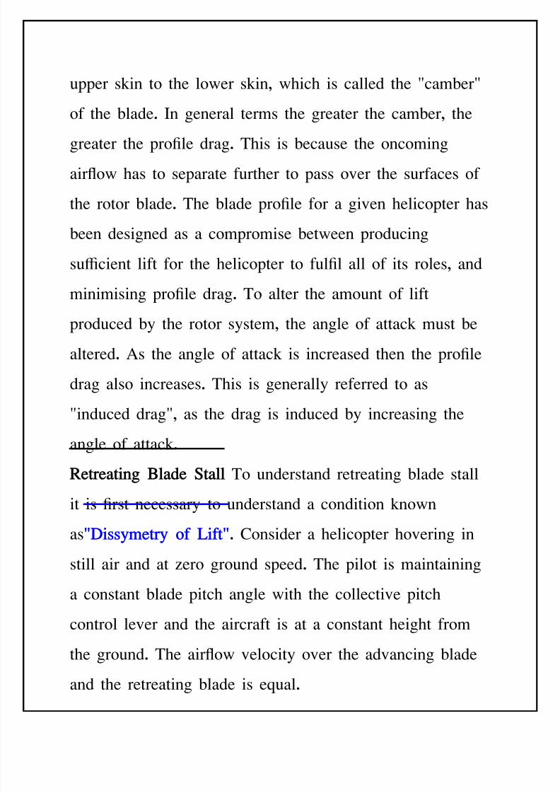
upper skin to the lower skin, which is called the @cam'er@
of the 'lade. In general terms the greater the cam'er, the
greater the pro4le drag. This is 'ecause the oncoming
airow has to separate further to pass over the surfaces of
the rotor 'lade. The 'lade pro4le for a given helicopter has
'een designed as a compromise 'etween producing
sucient lift for the helicopter to ful4l all of its roles, and
minimising pro4le drag. To alter the amount of lift
produced 'y the rotor system, the angle of attack must 'e
altered. As the angle of attack is increased then the pro4le
drag also increases. This is generally referred to as
@induced drag@, as the drag is induced 'y increasing the
angle of attack.
Re!re"!in Bl"$e S!"ll To understand retreating 'lade stall
it is 4rst necessary to understand a condition known
as@Diss*)e!r* of Lif!@. -onsider a helicopter hovering in
still air and at ero ground speed. The pilot is maintaining
a constant 'lade pitch angle with the collective pitch
control lever and the aircraft is at a constant height from
the ground. The airow velocity over the advancing 'lade
and the retreating 'lade is eEual.
8/11/2019 Introduction to Helicopters Aerodynamics
http://slidepdf.com/reader/full/introduction-to-helicopters-aerodynamics 85/102
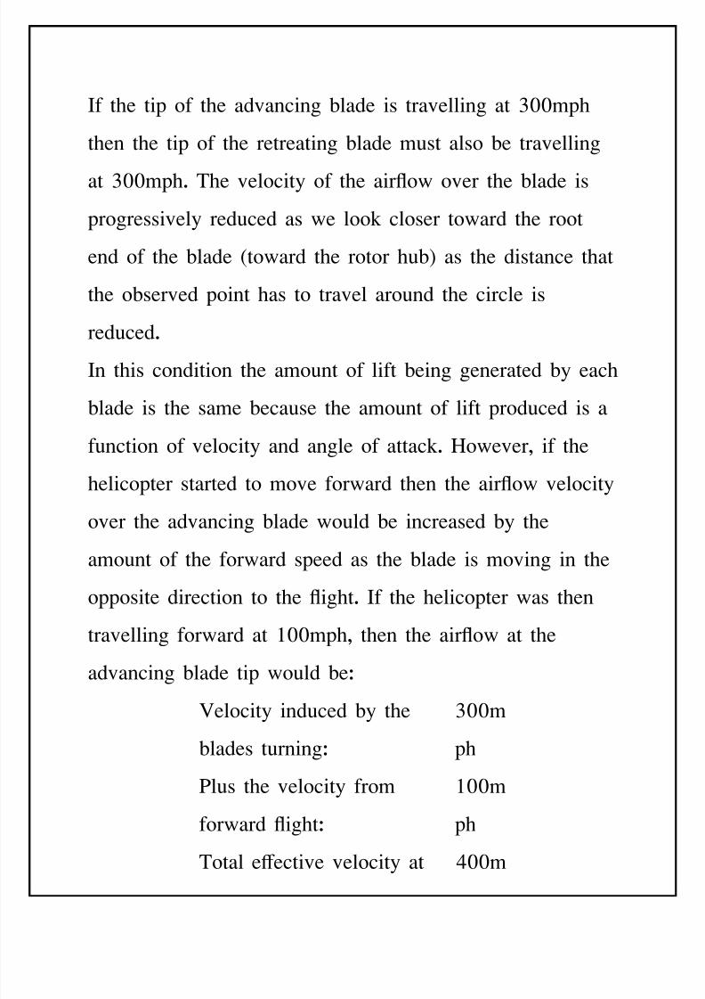
If the tip of the advancing 'lade is travelling at <55mph
then the tip of the retreating 'lade must also 'e travelling
at <55mph. The velocity of the airow over the 'lade is
progressively reduced as we look closer toward the root
end of the 'lade :toward the rotor hu'; as the distance that
the o'served point has to travel around the circle is
reduced.
In this condition the amount of lift 'eing generated 'y each
'lade is the same 'ecause the amount of lift produced is a
function of velocity and angle of attack. "owever, if the
helicopter started to move forward then the airow velocity
over the advancing 'lade would 'e increased 'y the
amount of the forward speed as the 'lade is moving in the
opposite direction to the ight. If the helicopter was then
travelling forward at 55mph, then the airow at the
advancing 'lade tip would 'eJ
0elocity induced 'y the
'lades turningJ
<55m
ph
9lus the velocity from
forward ightJ
55m
ph
Total e+ective velocity at 755m
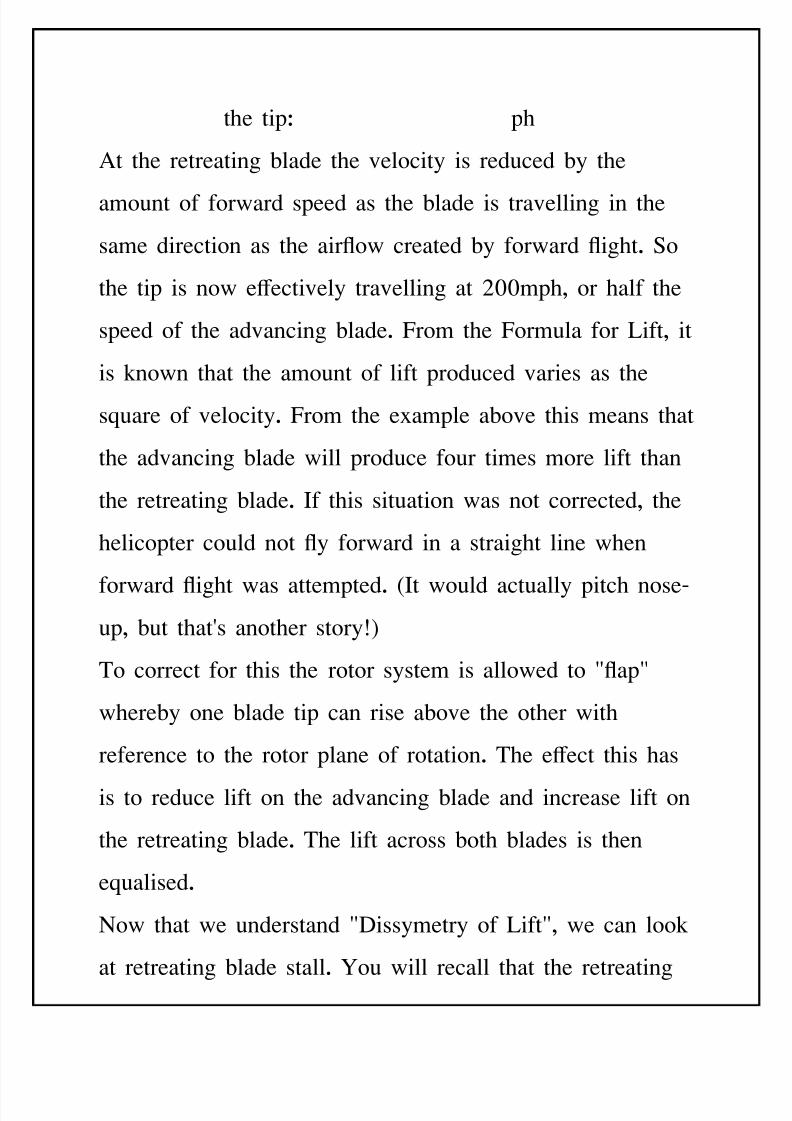
8/11/2019 Introduction to Helicopters Aerodynamics
http://slidepdf.com/reader/full/introduction-to-helicopters-aerodynamics 86/102
the tipJ ph
At the retreating 'lade the velocity is reduced 'y the
amount of forward speed as the 'lade is travelling in the
same direction as the airow created 'y forward ight. $o
the tip is now e+ectively travelling at 855mph, or half the
speed of the advancing 'lade. From the Formula for Lift, it
is known that the amount of lift produced varies as the
sEuare of velocity. From the e=ample a'ove this means that
the advancing 'lade will produce four times more lift than
the retreating 'lade. If this situation was not corrected, the
helicopter could not y forward in a straight line when
forward ight was attempted. :It would actually pitch noseB
up, 'ut that(s another storyO;
To correct for this the rotor system is allowed to @ap@
where'y one 'lade tip can rise a'ove the other with
reference to the rotor plane of rotation. The e+ect this has
is to reduce lift on the advancing 'lade and increase lift on
the retreating 'lade. The lift across 'oth 'lades is then
eEualised.
Cow that we understand @Dissymetry of Lift@, we can look
at retreating 'lade stall. Pou will recall that the retreating
8/11/2019 Introduction to Helicopters Aerodynamics
http://slidepdf.com/reader/full/introduction-to-helicopters-aerodynamics 87/102
'lade has a lower airow velocity than the advancing 'lade
in forward ight. If we were to accelerate our helicopter
from the a'ove e=ample to <55mph, then the advancing
'lade would have an airow velocity of 355mph, and the
retreating 'lade would 'e ero. For the 'lade to produce
lift it must have some airow over it, so in this case the
'lade would @stall@. $tall is a condition where there is a
'reakdown of smooth laminar airow over the surfaces of
an aerofoil :rotor 'lade;.
%ith each 'lade entering a stall condition as it passed
down the left side of the helicopter, forward ight could
not 'e maintained at this speed. *efore the 'lade actually
stalled it would produce a series of harsh vi'rations known
as @'u+eting@. %hen a manufacturer produces a new
helicopter, the speed at which this 'u+eting will occur is
esta'lished during ight test trials and a lower 4gure is
su'seEuently pu'lished which is commonly known as 8NE
or 8eloci!* 5 Ne+er Ecee$ . This esta'lishes a safety
margin 'elow the speed where retreating 'lade stall may
occur.
8/11/2019 Introduction to Helicopters Aerodynamics
http://slidepdf.com/reader/full/introduction-to-helicopters-aerodynamics 88/102
Airo( Re+ers"l Airow eversal will normally occur
'efore retreating 'lade stall. Pou will recall that the airow
velocity is progressively reduced along a 'lade from 'eing
highest at the tip, to lowest at the root end.
If the velocity is <55mph at the tip, it is feasi'le for the
velocity to 'e as low as 55mph at the root. Therefore
when forward speeds as low as 55mph :appro=. 35 Nts;
are encountered, the root end of the 'lade is e+ectively
stalled. %hen higher speeds are attempted, the airow
across the root end of the 'lade can actually reverse and
travel from the trailing edge to the leading edge. This is
'ecause the airow velocity produced 'y the forward speed
is greater than that 'eing produced 'y the rotor 'lades
turning. Airow reversal is counterBproductive to producing
lift and rotor thrust.
To reduce the e+ects of lift variations from the root to the
tip of a 'lade the manufacturer will either twist the 'lade
along its length, or apply a taper to the 'lade. Twist is the
reduction of angle of attack from the root to the tip.
emem'er that lift increases with velocity and angle of
attackQ *ecause the tip is travelling faster than the root, the
8/11/2019 Introduction to Helicopters Aerodynamics
http://slidepdf.com/reader/full/introduction-to-helicopters-aerodynamics 89/102
angle of attack must 'e reduced toward the tip to maintain
the same amount of lift at the tip and the root ends. Taper
is the gradual reduction of the width of a 'lade from the
leading edge to the trailing edge. A straight line drawn
from the centre of the leading edge to the centre of the
trailing edge is called the @-hord Line@. *y reducing the
chord line from the root to the tip, less surface area is
availa'le for the airow to act on to produce lift.
n higher speed helicopters :%estland Lyn=;, the root end
of the 'lade is a 'lade spar and attachment area only. The
aerofoil shape does not start until several feet out from the
centre of the rotor system. This is done to reduce the
e+ects of airow reversal 'y placing the liftBproducing
surface further out where the rotational velocity is higher.
Air Co)pressi%ili!* Air is a gas and therefore conforms to
the properties of a gas, namely the a'ility to 'e
compressed. %hen studying aerodynamics however, air
must also 'e considered to have some of the properties of a
uid. A uid has far less compressi'ility than a gas.
%hen the airow over a rotor 'lade strikes the leading
edge, it is split into two streams, which then pass a'ove
8/11/2019 Introduction to Helicopters Aerodynamics
http://slidepdf.com/reader/full/introduction-to-helicopters-aerodynamics 90/102
and 'elow the 'lade. At lower speeds, this splitting action
occurs relatively easily reEuiring little energy. As speeds
increase, the air striking the leading edge tends to 'e
compressed 'efore separating into two streams. Think of
this as slapping your hand onto a water surface. If you
chop your hand into the water, like a karate chop, you can
separate the water fairly easily. If you slap your open hand
onto the water however, it takes considera'ly more force to
su'merge your hand. The airow at the leading edge is
very similar. As the air at the leading edge is progressively
compressed, it reEuires considera'ly more rotor thrust for
the 'lade to separate the airow into two streams.
C*clic Con!rol S!ic# $esin "elicopter designers are
forever trying to 4t more eEuipment into the cockpit of a
helicopter to satisfy market demands. At the same time,
they are trying to minimise the weight of the aircraft so
that it can carry and lift more. %hen designing the pilot
and copilots workstations the designers attempt to place the
controls in a position where the crew can easily and
comforta'ly operate all controls without e=cessive reaching
8/11/2019 Introduction to Helicopters Aerodynamics
http://slidepdf.com/reader/full/introduction-to-helicopters-aerodynamics 91/102
or stretching. This places limitations on the amount of
movement availa'le at the cyclic control stick.
The designers could feasi'ly arrange the controls such that
very small amounts of stick movement were reEuired for
normal ight, 'ut this would make control in the hover
very dicult as the controls would 'e super sensitive to
small inputs. For this reason, the controls are arranged so
that a reasona'le control movement is availa'le, generally
3B6 inches of stick movement depending on the particular
aircraft model.
A+"il"%le Enine &o(er The engine system in a helicopter
is reEuired to provide power for a range of demands, not
only the rotor system. In the rotor system, thrust is reEuired
to overcome drag. As speed is increased, so does drag. If
more power is availa'le to overcome drag, then potentially
the helicopter can y faster.
It can 'e seen that from these factors that it is very
dicult for helicopter designers to increase the ma=imum
speed of a helicopter as many factors are 'eyond their
control. )uch research and development has occurred in
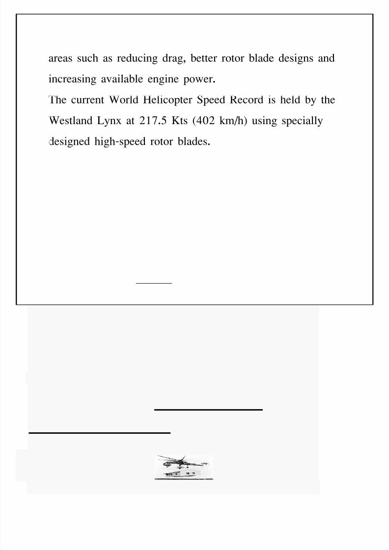
8/11/2019 Introduction to Helicopters Aerodynamics
http://slidepdf.com/reader/full/introduction-to-helicopters-aerodynamics 92/102
areas such as reducing drag, 'etter rotor 'lade designs and
increasing availa'le engine power.
The current %orld "elicopter $peed ecord is held 'y the
%estland Lyn= at 81./ Nts :758 kmh; using specially
designed highBspeed rotor 'lades.
USES O-
HELICO&TER
Sikorsky S-64 Skycrane lifting a prefab house
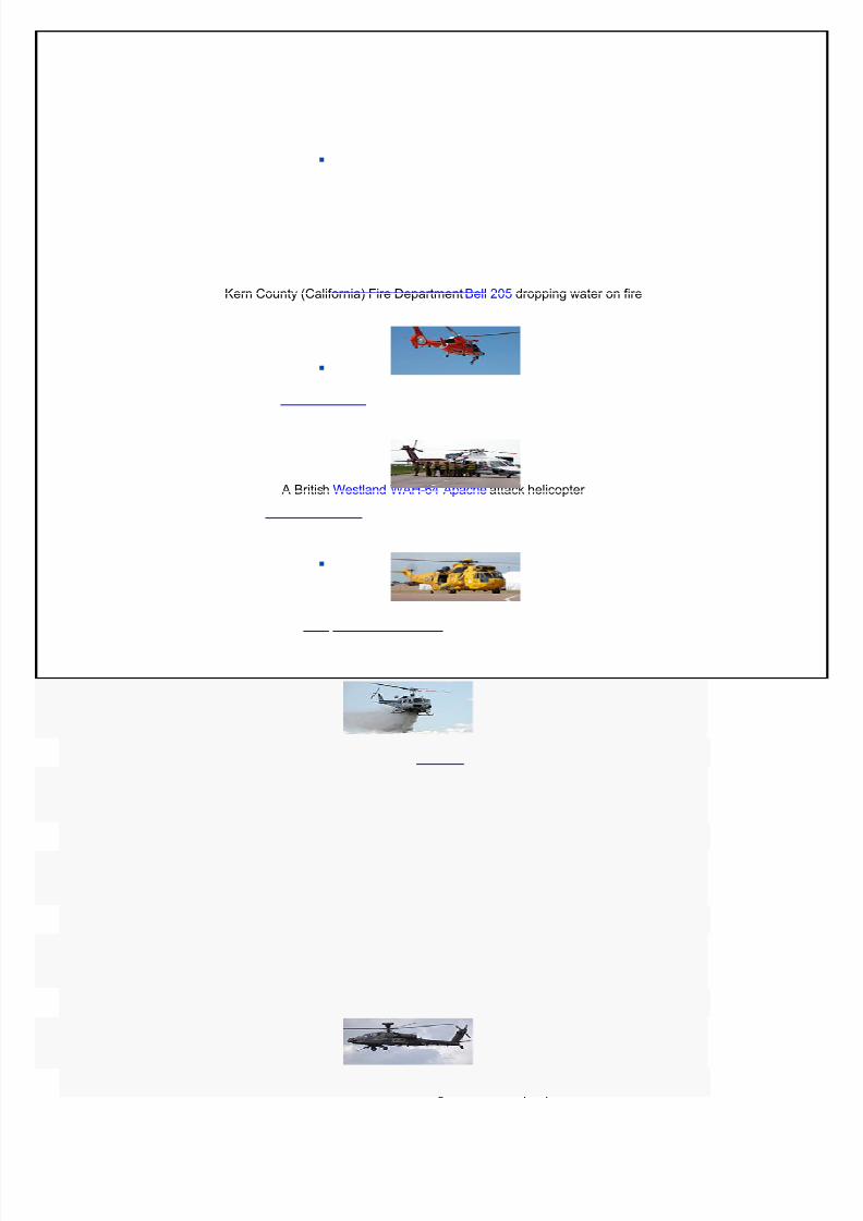
8/11/2019 Introduction to Helicopters Aerodynamics
http://slidepdf.com/reader/full/introduction-to-helicopters-aerodynamics 93/102
Kern County (California) Fire Department Bell !" #ropping $ater on fire
% British &estlan# &%'-64 %pache attack helicopter
''-6" Dolphin #emonstrating hoist rescue capability
% Sikorsky S-6C air ambulance being loa#e# by fire-fighters
*%F &estlan# Sea King for rescue of people
8/11/2019 Introduction to Helicopters Aerodynamics
http://slidepdf.com/reader/full/introduction-to-helicopters-aerodynamics 94/102
A helicopter used to carry loads connected to long ca'les
or slings is called an aerial crane. Aerial cranes are used to
place heavy eEuipment, like radio transmission towers and
large air conditioning units, on the tops of tall 'uildings, or
when an item must 'e raised up in a remote area, such as
a radio tower raised on the top of a hill or mountain.
"elicopters are used as aerial cranes in the logging industry
to lift trees out of terrain where vehicles cannot travel and
where environmental concerns prohi'it the 'uilding of
roads. These operations are referred to as logline 'ecause
of the long, single sling line used to carry the load.
"elitack is the use of helicopters to com'at wildland
4res.The helicopters are used for aerial 4re4ghting :or
water 'om'ing; and may 'e 4tted with tanks or
carry heli'uckets. "eli'uckets, such as the *am'i 'ucket,
are usually 4lled 'y su'merging the 'ucket into lakes,
rivers, reservoirs, or porta'le tanks. Tanks 4tted onto
helicopters are 4lled from a hose while the helicopter is on
the ground or water is siphoned from lakes or reservoirs
through a hanging snorkel as the helicopter hovers over the
water source. "elitack helicopters are also used to deliver
8/11/2019 Introduction to Helicopters Aerodynamics
http://slidepdf.com/reader/full/introduction-to-helicopters-aerodynamics 95/102
4re4ghters, who rappel down to inaccessi'le areas, and to
resupply 4re4ghters. -ommon 4re4ghting helicopters
include variants of the *ell 85/ and the &rickson $B
37Aircrane helitanker.
"elicopters are used as air am'ulances for emergency
medical assistance in situations when an am'ulance cannot
easily or Euickly reach the scene. "elicopters are also usedwhen a patient needs to 'e transported 'etween medical
facilities and air transportation is the most practical method
for the safety of the patient. Air am'ulance helicopters are
eEuipped to provide medical treatment to a patient while in
ight. The use of helicopters as an air am'ulance is often
referred to as )&D&0A-, and patients are referred to as
'eing @airlifted@, or @medevaced@.
9olice departments and other law enforcement agencies use
helicopters to pursue suspects. $ince helicopters can
achieve a uniEue aerial view, they are often used in
conunction with police on the ground to report on suspects(
locations and movements. They are often mounted with
lighting and heatBsensing eEuipment for night pursuits.
8/11/2019 Introduction to Helicopters Aerodynamics
http://slidepdf.com/reader/full/introduction-to-helicopters-aerodynamics 96/102
)ilitary forces use attack helicopters to conduct aerial
attacks on ground targets. $uch helicopters are mounted
with missile launchers and miniguns. Transport
helicopters are used to ferry troops and supplies where the
lack of an airstrip would make transport via 4=edBwing
aircraft impossi'le. The use of transport helicopters to
deliver troops as an attack force on an o'ective is referred
to as Air Assault. #nmanned Aerial $ystems :#A$;
helicopter systems of varying sies are 'eing developed 'y
companies for
military reconnaissance andsurveillance duties. Caval forces
also use helicopters eEuipped with dipping sonar for antiB
su'marine warfare, since they can operate from small ships.
il companies charter helicopters to move workers and
parts Euickly to remote drilling sites located out to sea or
in remote locations. The speed over 'oats makes the high
operating cost of helicopters cost e+ective to ensure that oil
platforms continue to ow. 0arious companies specialie in
this type of operation.
ther uses of helicopters include, 'ut are not limited toJ
8/11/2019 Introduction to Helicopters Aerodynamics
http://slidepdf.com/reader/full/introduction-to-helicopters-aerodynamics 97/102
Aerial photography
)otion picture photography
&lectronic news gathering
eection seismology
$earch and escue
Tourism or recreation
Transport
&A,AN HANS
HELICO&TERS
&"("n H"ns Helicop!ers Li)i!e$ is
a helicopter service company 'ased in India. The
operations are 'ased at 0ile 9arle:%est;. ther
than providing helicopter services to C!- to
8/11/2019 Introduction to Helicopters Aerodynamics
http://slidepdf.com/reader/full/introduction-to-helicopters-aerodynamics 98/102
its o+Bshore locations, this pu'lic
sector company is often engaged for providingservices to various state governments in India,
particularly in CorthBeast India, 0aishno
Devi "elicopter service for devotees.
His!or*
9awan "ans was incorporated on / cto'er
26/ as the "elicopter -orporation of India
:"-L;, the country(s national helicopter company
with the o'ective of providing helicopter
support services to the oil sector for its o+Bshore
e=ploration operations, services in remote areas
and charter services for promotion of tourism. It
is a government owned enterprise with 16./R in
government hands S 8./R with C!-.
C!- has upped its stake to 72R recently, a
8/11/2019 Introduction to Helicopters Aerodynamics
http://slidepdf.com/reader/full/introduction-to-helicopters-aerodynamics 99/102
move that will see the eEuity 'ase of 9""L
'eing enhanced to 87/ crore from the e=isting
< crore.
The corporate oce is located at Coida with
regional oces at Delhi and )um'ai. The
company has a net worth of <1,5/ million and
eEuity capital is ,<1 million. 9awan "ans is
@Approved )aintenance -entre of &urocopter@
and also the 4rst I$ 255 J 8555 certi4ed
aviation company in India.
It o+ers helicopter services for B
+ $hore operations
Inter island transportation
-onnecting inaccessi'le areas
-ustoms and pipeline surveillance
-asualty and rescue work
8/11/2019 Introduction to Helicopters Aerodynamics
http://slidepdf.com/reader/full/introduction-to-helicopters-aerodynamics 100/102
-harter services
0I9 transportation
Film shooting and aerial photography
Flower dropping and other
-ustomied services.
CONCLUSION
&ven though the concept of the helicopter is argua'ly
older than that of the airplane, there is still a great
amount of research and advancement yet to occur. As the

8/11/2019 Introduction to Helicopters Aerodynamics
http://slidepdf.com/reader/full/introduction-to-helicopters-aerodynamics 101/102
political climate of our world continues to change and
military conicts approach the smallBscale ur'an warfare
of recent years, the importance of the helicopter will
continue to grow. It is rather ironic that an idea 4rst
conceived long 'efore the -ommon &ra will 'e key to
winning military conicts in the 8st century.
otary wing research and development is a comple=
interrelated challenge. The advanced tools used are
-omputational uid dynamics :-FD;, Finite element
method :F&);, and -omputational structural dynamics
:-$D; for physical understanding of comple=
aerodynamics and structural phenomena. Integration of
these will ena'le us to design rotorcraft, which will have
superior productivity, enlarged mission capa'ilities and
improved environmental acceptance.

8/11/2019 Introduction to Helicopters Aerodynamics
http://slidepdf.com/reader/full/introduction-to-helicopters-aerodynamics 102/102
The future of helicopter is 'right with its a'ility to land
in any small clear areaG the helicopter 4nds use in air
ta=i service, police work, Inter city mail, and rescue
work, power line patrolling and other areas. The
development is still to continue.